

Page 1
Instruction Manual
Printed in the U.S.A.
Copyright 2011 Monarch Instrument, all rights reserved
1071-4145-110R-0911
MONARCH INSTRUMENT
F2A1X
Frequency to Analog Converter Module
15 Columbia Drive
Amherst, NH 03031 USA
Phone: (603) 883-3390
Fax: (603) 886-3300
E-mail: support@monarchinstrument.com
Website: www.monarchinstrument.com
Page 2

Safeguards and Precautions
1. Read and follow all instructions in this manual carefully, and
retain this manual for future reference.
2. Do not use this instrument in any manner inconsistent with
these operating instructions or under any conditions that
exceed the environmental specifications stated.
3. Be sure the power supplied to this instrument matches the
specification indicated on the rear panel of the instrument.
4. Be sure all power is removed before making or removing any
connections to or from this instrument.
5. There are no user serviceable parts in this instrument. Refer
service to a qualified technician.
6. This instrument is not intended for use in adverse or wet
environments. This may cause permanent damage and void
the warranty.
7. Do not allow cables extending from unit to come into contact
with rotating machinery, as serious damage to the equipment,
or severe personal injury or death may occur as a result.
8. This instrument may not be safe for use in certain hazardous
environments, and serious personal injury or death could occur
as a result of improper use. Please refer to your facility’s
safety program for proper precautions.
In order to comply with EU Directive 2002/96/EC on Waste
Electrical and Electronic Equipment (WEEE): This product
may contain material which could be hazardous to human health
and the environment. DO NOT DISPOSE of this product as
unsorted municipal waste. This product needs to be RECYCLED
in accordance with local regulations, contact your local authorities for
This page intentionally left blank.
Page 3

@CH_A/LOEND = 12 (or 1_SEC, HALF) Sets low end time. This allows a
min reading of 5 RPM, 60 RPM, or 120
RPM.
@CH_A/GATE Show Gate Speed. (Default is 12)
@CH_A/GATE = STD (1/100 Second) or FAST (1/1000 second). Sets Gate
Speed (Default is 1/100)
@DECPT Shows the number of decimal places
displayed
@DECPT = NONE, 1, 2, or 3 Sets the maximum number of decimal
places.
@DAC1/ FSCAL Shows Analog Out Full Scale
@DAC1/FSCAL = xxx.xx Sets the Reading value that the Analog
output will output Full Scale (5V or
20mA). Depends on TYPE.
@DAC1/0SCAL Shows Analog Out Zero Scale
@DAC1/0SCAL = xxx.xx Sets the Reading value that the Analog
output will output Zero Scale (0V or
4mA). Depends on TYPE. (Default is
0.00)
@DISPR Shows Display Update Rate
@DISPR = HALF or 1_SEC or 1.5_S. This sets the maximum display
update rate to one half a second, 1 second
or 1 ½ seconds between updates.
@SERNO Shows unit Serial Number
more information. This product may be returnable to your distributor for
recycling - contact the distributor for details.
Monarch Instrument’s Limited Warranty applies. See
www.monarchinstrument.com for details.
Warranty Registration and Extended Warranty coverage available
online at www.monarchinstrument.com.
TABLE OF CONTENTS
TABLE OF CONTENTS
1.0 OVERVIEW ............................................................................. 1
2.0 INSTALLATION ....................................................................... 1
2.1 Power ............................................................................ 2
2.2 Analog Out .................................................................... 2
2.2.1 Current Output Option............................................. 3
2.2.2 Voltage Output Option ............................................. 3
2.3 Sensor Input ................................................................. 3
3.0 USER PROGRAMMABLE HARDWARE SETTINGS ................. 5
3.1 Sensor Power Voltage ................................................. 6
3.2 Sensor Termination...................................................... 6
3.3 Input Coupling ............................................................... 6
4.0 USER PROGRAMMABLE SOFTWARE SETTINGS .................. 7
5.0 SPECIFICATIONS .................................................................... 8
6.0 OPTIONS AND ACCESSORIES / SENSORS ........................... 9
11
7.0 APPENDIX A - Serial Programming Commands ................ 10
Page 4

1.0 OVERVIEW
7.0 APPENDIX A - Serial programming Commands
The F2A1X Frequency to Analog Module converts frequency input into an
analog voltage (0 to 5Vdc) or current (4 to 20mAdc) output. The output is
electrically isolated from the rest of the unit. The input signal may be from an
external sensor (measuring RPM for example) or any source of digital signal
not exceeding 12 volts.
The F2A1X may be factory preprogrammed or user programmed using an
optional USB programming cable (see Options and Accessories section) for
any full scale output and input scale factor to provide an output of mV or mA
out for a given input signal.
The device is powered from 12 to 24Vdc and consumes less than 100mA and
can be ooperated free standing or can be mounted to a panel using the fixing
wings on either end of the device. The F2A1X accepts input signals from
optical, infrared, laser or 3-wire proximity sensors, or direct TTL or external
ac inputs. User settings include sensor supply voltage, AC/DC coupling and
input termination.
When ordering the user needs to specify either a 4 to 20 mA current output
or 0 to 5 Vdc voltage output and whether isolated outputs are required.
2.0 INSTALLATION
The F2A1X Frequency to Analog Module is housed in a mountable ABS
enclosure 80 x 40 x 28 mm (3.2 x 1.6 x 1.2 inches) excluding the mounting
wings. There are screw terminal connections on both ends of the unit.
1
Programming the unit requires the optional USB Programming Cable with
associated PM Remote software and a PC running Windows XP or later with
an available USB port.
All serial commands are @ then two or more characters or words separated
by a delimiter “/”. One or two numbers follow some commands. All valid
commands respond immediately with an “OK” or data, or “ERR” if incorrect.
Default Baud rate is 9600. Communication requires the User Programming
Cable.
@PI Product Information, Shows Product name \n Firmware revision \n
@C1 Shows all settings
@C2 Shows all settings with CR after each parameter
@D0 Sends current display value once
@D1 Sends display data continuously (at up to display update rate)
@D2 Stops sending data
@MX Sends Max reading
@MN Sends Min reading
@RE 32 Resets Max
@RE 64 Resets Min
@RE 96 Resets Max and Min
@CH_A/TYPE Shows current type
@CH_A/TYPE = RPM Sets scale to 60 so displays in RPM
@CH_A/TYPE = FREQ Sets scale to 1 so displays in hertz
@CH_A/TYPE = SCALE Scale mode. Enter Scale factor.
@CH_A/TYPE/SCALE = 30.00 This will set the SCALE factor to 30.00
@CH_A/INPUT Shows Sense of trigger input
@CH_A/INPUT = POS (or NEG) Sets the sense of the input trigger
@CH_A/LOEND Sets how long (in secs) with no pulses
before the unit outputs 0
10
Page 5

6.0 OPTIONS AND ACCESSORIES / SENSORS
T-5 Reflective Tape - 5 foot (1.5 m) roll, 0.5 inch (10 mm) wide
USB Programming Cable with PM Remote Software on CD:
Enables the user to program the F2A1X using a PC with
USB connection. The software also allows remote monitoring
of the RPM using a graphic display or an Excel
ROLS-W Remote Optical Laser Sensor with 8 foot cable
ROS-W Remote Optical Sensor with 8 foot cable
ROS-P-25 Remote Optical Sensor with 25 foot cable (must cut plug off)
ROS-HT-W-25 Remote Optical Sensor for high temperature applications
to 257 °F (125 °C) with 25 foot cable
GE-200HP Electromagnetic Inductive Spark Plug Sensor with 15 feet of
cable
IRS-W Infrared Sensor with 8 foot cable
TM
spreadsheet.
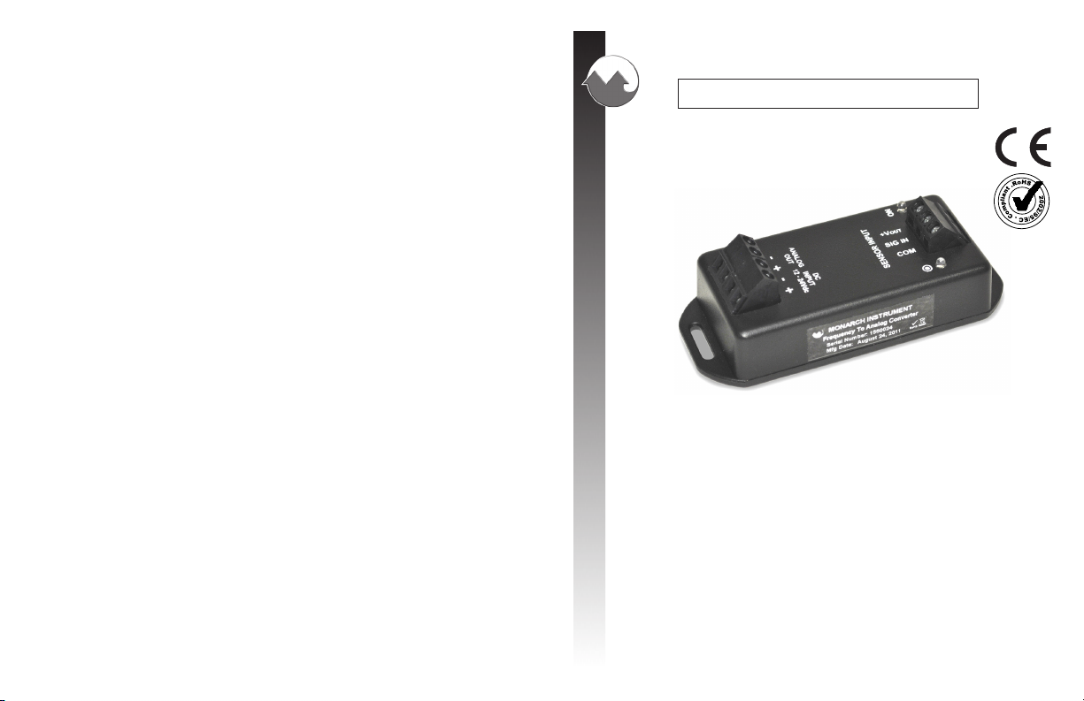
Figure 1 F2A1X Module – top view
Before mounting the unit to a panel all user options should be set. See
Sections 3 and 4.
2.1 Power
Power to the unit is connected to the 4 way terminal block marked DC
INPUT 12 – 24Vdc. Refer to Figure 2.1 above. Note that these inputs
are polarity sensitive. Connect a supply of 12 to 24Vdc (with a 150mA
source capacity) ensuring that the positive wire goes to the + terminal
and the common or negative wire goes to the – terminal.
2.2 Analog Out
The Analog Out terminals are the source for the voltage or current
output as ordered. These terminals are polarity sensitive and are marked
+ and – accordingly.
The F2A1X Frequency to Analog Module may be equipped with either
a Current Output or a Voltage Output depending on how the unit was
ordered. The Analog Out terminals are the source for the voltage or
current output. These terminals are polarity sensitive and are marked +
and – accordingly.
The ANALOG OUT is an OUTPUT. DO NOT CONNECT THE
DC POWER TO THESE TERMINALS.
9
2
Page 6

NOTE: The Full scale output settings must have been specified when
ordered or may be user programmed using the User
Programming Cable.
2.2.1 Current Output Option
The current output is 4 to 20 mA. This output is a current source
and has a 10 Vdc internal compliance voltage. The maximum load
that may be connected is 450 ohms.
Typical connections are as follows: (Shown
right)
Connections for current out are to the terminals
marked ANALOG OUT. Connect the Positive
side of the load to the terminal marked + and the
other side of the load to the terminal marked -.
2.2.2 Voltage Output Option
The voltage output is 0 to 5 Vdc.
Connections for voltage out are to the terminals
marked ANALOG OUT. Connect the Positive
side of the load to the terminal marked + and the
negative or common side of the load to the terminal marked -.
2.3 Sensor Input
The SENSOR INPUT is the input terminal used to connect an external
sensor or trigger source. There is a voltage output that may be used to
power an external sensor (5 or 12 Vdc – user selectable at 75mA max).
The system supports two wire inputs (Signal and Common) or three
wire sensors (Supply, Signal and Common). Three wire sensors can be
open collector types – NPN or PNP, TTL output or –ve output types.
5.0 SPECIFICATIONS
Input Range: 0.1 to 10 KHz, 5 to 600,000 RPM
Accuracy: 0.005%
mA Option: 4 to 20 mA out, 16 bit resolution 10Vdc compliance
voltage. Zero and full scale settings as specified when
ordered or user programmable using USB Programming
Cable and PM Remote Software
Vdc Option: 0 to 5 Vdc out, 5 mA 16 bit resolution. Zero and full
scale settings as specified when ordered or programmable
using USB Programming Cable and PM Remote Software
Resolution: 76 microvolts or 30.5 micro amps
Dimensions: L x W x H = 80 x 40 x 28 mm (3.2 x 1.6 x 1.2 inches)
excluding the mounting wings
Power Supply: 12 to 24Vdc +5% @ 150mA max
Input: TTL input or +3 Vac to +12 Vac
Sensor Supply: 5Vdc or 10 Vdc at 75 mA – User selectable
This product is CE certified and ROHS compatible.
Manufactured in an ISO9001 facility.
For troubleshooting information and technical support visit
www.monarchinstrument.com.
3
8
Page 7

4.0 USER PROGRAMMABLE SOFTWARE
SETTINGS
All the operational settings of the F2A1X
Frequency to Analog Module can be set remotely
using the PM Remote PC Software and the
optional User Programming Cable (UPC). This
cable plugs into the unit via the phone jack socket
below the SENSOR INPUT terminal block as
shown here and into a USB port on the PC.
Settings that can be programmed include input scaling, analog output full
scale and offset, input pulse polarity and update rate. In addition you can
view real time data on the PC – refer to the PM Remote manual and help
screen.
Connections and their functions are as follows:
+Vout Positive +5 or +10 Vdc (User selectable) to provide power to
optical, laser, infrared or amplified magnetic sensors. Maximum
load is 75 mA dc.
SIG IN Input signal from signal sources or speed sensor. Accepts
TTL pulses or ac signals, unipolar and bipolar, from +3 to
+12 Volts. Connect the signal wire from three wire sensors or
the positive side of two wire sources to this terminal. Typical
input impedance is 10 Kohms.
COM Common or Negative connection for both signal and power
from most sensors/sources.
Refer to the User Settings section for input option settings. Typical
connection for Monarch standard sensors is shown below:
Figure 2 Sensor Connection Detail
7
4
Page 8

Figure 3 Signal Source Connection Detail
3.0 USER PROGRAMMABLE HARDWARE
SETTINGS
There are several settings relating to the sensor input that can be set by the
user.
The settings are done by moving jumpers on the circuit board inside the
housing. To access these jumpers REMOVE ALL WIRING FROM THE
UNIT. Then remove the two screws on the bottom of the unit and remove the
base exposing the circuit board as shown below.
There are three jumpers as shown in Figure 4. These are:
3.1 Sensor Power Voltage
This jumper adjusts the supply voltage to the external sensor. Can be
set as +5Vdc or +10Vdc depending on the sensor used. Factory Default
is +5V.
3.2 Sensor Termination
This jumper sets the input termination. Can be set HI for 10k pull up
resistor (to sensor supply voltage) for NPN type open collector sensors
(factory default) or LO for 10k pull down resistor (to Common) for
PNP type open collector sensors or none (remove jumper altogether)
high impedance input for external termination.
3.3 Input Coupling
This jumper sets the input coupling for the external signal. Can be set to
DC (default) for most digital input sources or AC for sine wave and
bidirectional sources or sensors that provide negative going pulses.
Once the jumpers have been set, replace the base and the two screws.
Figure 4 Exposed Circuit Board showing Program Jumpers
5
6
 Loading...