

Page 1
MONARCH INSTRUMENT
Instruction Manual
Data-Chart Data-Chart
Data-Chart
Data-Chart Data-Chart
Paperless Recorder
IMPORTANT!
Please format all floppy disks in
the Recorder prior to use.
Because floppy disks are volatile,
do not use disks for more than
2-3 months. Also, use a floppy
cleaning disk every 4 months to
clean the heads.
®
2000 2000
2000
2000 2000
15 Columbia Drive
Amherst, NH 03031-2334 USA
Phone: (603) 883-3390
Fax: (603) 886-3300
E-mail: support@monarchinstrument.com
Website: www.monarchinstrument.com
Page 2

Page 3

MONARCH INSTRUMENT
Instruction Manual
®
Data-Chart Data-Chart
Data-Chart
Data-Chart Data-Chart
2000 2000
2000
2000 2000
Overview
Chapter 1 .................... General Information
Chapter 2 .................... Installation and Wiring
Chapter 3 .................... Getting Started
Chapter 4 .................... Operation
Chapter 5 .................... Programming
Chapter 6 .................... Calibration
Chapter 7 .................... Get Data Software
Appendix A ................. Configuring a 1-5 Vdc input for a 0-250
psig pressure transducer
Appendix B ................. Configuring a 4-20 mA input to equal
0 to 150 gpm
Appendix C ................. Configuring a J type T/C input for a
100-750° C range
Appendix D ................. Configuring the Totalizer
Warranty
Return Information
Page 4

Page 5

SAFETY NOTICE
This Safety Notice has been included to emphasize the DANGER OF HAZARDOUS VOLTAGES on the
REAR TERMINAL PANEL of your instrument. USE EXTREME CAUTION WHEN INSTALLING OR
SERVICING your instrument. Please read the entire contents of the Installation and Wiring Chapter of
this manual before attempting to install or service your instrument.
WARNING
Use Extreme caution when servicing the rear terminal of your instrument.
Page 6

Page 7

Chapter 1 General Description
Introduction ..................................................................................................................................................... 1-1
1.1 Recorder Description ...............................................................................................................................1-2
1.1.1 Inputs ............................................................................................................................................. 1-2
1.1.2 Instrument Size .............................................................................................................................. 1-2
1.1.3 Menus ............................................................................................................................................ 1-2
1.1.3.1 Display Menu ........................................................................................................................ 1-3
1.1.3.2 Program Menu ...................................................................................................................... 1-3
1.1.3.3 Function Menu ......................................................................................................................1-3
1.1.3.4 Hidden Menu ........................................................................................................................1-3
1.1.4 Memory ..........................................................................................................................................1-3
1.1.5 Clock ..............................................................................................................................................1-3
1.1.6 Recorder Construction ...................................................................................................................1-3
1.2 Recording Options ...................................................................................................................................1-4
1.2.1 Floppy Disk Drive ...........................................................................................................................1-4
1.2.2 PCMCIA Memory Card ................................................................................................................... 1-4
1.2.3 Zip Drive .........................................................................................................................................1-4
1.3 Recorder Options ....................................................................................................................................1-4
1.3.1 Digital Input and Output .................................................................................................................. 1-4
1.3.2 Communications Interface ..............................................................................................................1-4
1.4 Specifications ..........................................................................................................................................1-5
Page 8

Page 9

Chapter 1 General Description
CHAPTER 1
STATUS LINE
GRAPHICS AREA
4/17/01 15:52:35
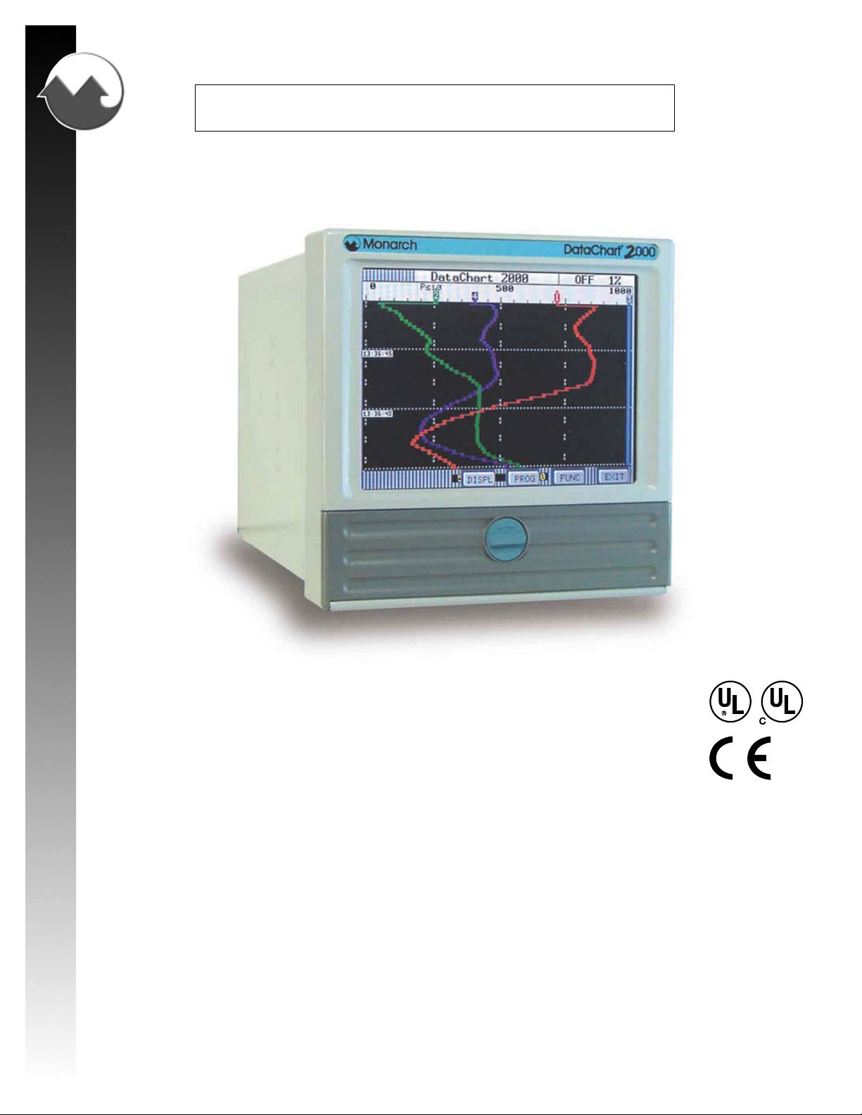
Figure 1-1 Solid State Data Recorder
This manual is a user reference guide for the Solid State Paperless Data Recorder (Figure 1-1). The manual
provides detailed instruction for installation, operation, programming, calibration and maintenance of the instrument.
The recorder is a sophisticated piece of equipment that requires some level of programming before use. The user is
advised to read this manual in its entirety before proceeding with the installation and programming. Refer to Chapter
3, Getting Started for minimum configuration. Step by step instructions for a few sample applications are included
in Appedixes A-D.
Page 1-1
Page 10

Chapter 1 General Description
1.1 Recorder Description
The Solid State Data Recorder is a Paperless Recording instrument. Data is stored on either an internal floppy
disk, a removable PCMCIA memory card or a Zip Drive.
All data is stored in MSDOS format and may be archived or analyzed on any IBM compatible PC running Microsoft
Windows 3.1 or Windows 95/98 using the available Companion Software. The instrument retains all the features of
a traditional Paper Chart Recorder by virtue of its large STN monochrome or TFT color Liquid Crystal Display (LCD)
which presents the data in the traditional chart mode as well as in bar graph or digital numeric form.
The unit has many features and functions which are unique and cannot be performed on traditional paper recorders,
such as data compression and historic data browsing. The recorder is programmed via a touch screen keypad on
the display .
The recorder will measure and process up to six direct inputs, calculated, conditional, or external points for logging,
trending, or data manipulation.
If direct inputs are not desired, the Data Recorder will accept up to fifteen points from a combination of calculated,
conditional, or external point types.
1.1.1 Inputs
Direct input sources may come from voltage, current, dry contacts, thermocouple, or RTD sources. The
voltage and current ranges accepted by the instrument include: ±150 mV , ±1.25 V , ±2.5 V , ±12.5 V, and ±25 V ;
4 to 20 mA, 0 to 20 mA and 10 to 50 mA current. Thermocouple inputs include T ype J,K,T,E,R,S,B,C and N.
RTD inputs accepted include 10 ohm Cu, 100 ohm Platinum, 200 ohm Platinum, 120 ohm Nickel and 1000
ohm Nickel.
1.1.2 Instrument Size
The instrument is sized to fit in a DIN standard panel cutout of 5.43 inches x 5.43 inches [138 mm x 138 mm]
and requires 7.41 inches [188.2 mm] behind panel depth, not including power and input source cable space
needed. Actual dimensions of the instrument are shown in Figure 2-1 Recorder Dimensions in Chapter 2 of this
manual.
1.1.3 Menus
The instrument’s features are accessed through a series of menus. Press the MENU button displayed in the
bottom right hand corner of the LCD screen. The ST A TUS bar along the top of the screen displays the various
recorder parameters. (Refer to Section 3.1). The Command Button Bar contains three user programming option
buttons - DISPLay , PROGram, and FUNCtion (see Figure 1-2 below). Each menu level features easy-to-follow
prompts that simplify operation.
DISPL
Figure 1-2 The Command Button Bar
Page 1-2
Page 11

Chapter 1 General Description
1.1.3.1 Display Menu
The Display Menu is accessed by pressing the Display button (DISPL) on the Command Button Bar. This
menu allows you to display any programmed point or series of points, or any current alarm or series of
alarms on the STATUS line along the top of the display. The version of operating software can also be
shown in a pop up window.
1.1.3.2 Program Menu
The Program Menu is accessed by pressing the Program button (PROG) on the Command Button Bar.
This Menu item may be passcode protected. The Program Menu allows you to define the system operating
parameters. Menu driven prompts, answered by yes, no or by entering the desired value, enable you to
customize the instrument to meet your application requirements. Refer to Chapter 5 for detailed instructions
on programming.
1.1.3.3 Function Menu
The Function Menu is accessed by pressing the Function button (FUNC) on the Command Button Bar .
This Menu item may be passcode protected. The Function Menu allows you to Activate, Bypass, and/or
Reset a point. This menu also allows you to change between high and low display chart speed or record
speed, turn Alarm Check on or off, and choose Scale Set 1 or 2.
1.1.3.4 Hidden Menu
The Hidden Menu can only be accessed by pressing a certain combination of buttons and may be passcode
protected. This menu allows you to Initialize the recorder, set Passcodes, perform Calibrations and
perform Diagnostics on the recorder. Refer to Chapter 4 for det ailed information.
1.1.4 Memory
All the Random Access Memory (RAM) in the Recorder is battery backed. This enables the unit to recover in
the event of a mains failure with minor data loss. Any programming will be protected in the event of power
removal and past browse data is maintained in the off state. The battery is a Non-rechargeable lithium and will
keep memory intact for at least 12 months.
1.1.5 Clock
A real time clock monitors the time and date in the event of a power loss. It uses the same battery as the
Random Access Memory.
1.1.6 Recorder Construction
The Data Recorder features modular construction. Power Supply and Analog conditioning modules are
conveniently accessible for fast and simple troubleshooting and/or removal. The floppy disk, PCMCIA or Z ip
drive can be accessed through the front of the unit.
Page 1-3
Page 12

Chapter 1 General Description
1.2 Recording Options
The Recorder can be ordered with one of three storage mediums: a standard PC compatible floppy disk drive,
an industry-standard PCMCIA memory card drive, or a Zip drive. The optional Companion Software supports al l
three media types.
1.2.1 Floppy Disk Drive
The Floppy disk drive uses PC compatible 3½ inch (89mm) floppy disks. These disks store 1.44 Megabytes
of data which translates to approximately 700,000 data samples (each sample is 16 bits). The disks are
magnetic media and the drives are mechanical. This limits their use in harsh environments where vibration or
temperature is a problem, but they are convenient as they are very inexpensive and can simply be plugged into
any IBM compatible PC.
1.2.2 PCMCIA Memory Card
The PCMCIA card (Personal Computer Memory Card Interface Association) is a small solid state card
containing Flash memory . The PCMCIA drive supports memory cards up to 200 Megabytes in size which is
approximately 100,000,000 data samples. The cards do require a special drive in your PC which is readily
available, inexpensive and already standard on many laptops and desktop machines. Contact your dealer
for details.
NOTE: It is recommended that a Sandisk 4-200 Meg Flash card be used.
1.2.3 Zip Drive
The Zip Drive stores 100 Megabytes of information which is approximately 50,000,000 samples for a 100
Megabyte Disk. This Recorder does not support 250 Megabyte Zip drives.
1.3 Recorder Options
Additional functions and capabilities can be added to the Recorder and are described in the following paragraphs.
1.3.1 Digital Input and Output
This option provides three or six mechanical form C (Normally Open, Common, Normally Closed contacts)
relay outputs capable of switching 250 V ac as well as three isolated digital control input s, or three or six solid
state open collector type contacts able to switch 30 Vdc at 0.5 Amps. The relay outputs can be programmed
to respond to alarm events while the digital inputs can be used to trigger events such as changing recording
speeds or stopping and starting recording.
1.3.2 Communications Interface
There are two communications options available:
1. An isolated RS232/RS485 interface using the Modbus protocol with the recorder acting as a slave device
in a Modbus RTU or Modbus ASCII environment.
2. An 802.3 compatible Ethernet option with RJ45 four wire connection.
Page 1-4
Page 13

Chapter 1 General Description
1.4 Specifications
OPERATING
Input Signals DC Voltage: Linear, Industrial square root, Logarithmic
Thermocouple: Resolution 0.1°C
RTD: Base accuracy 0.2% or 0.5 °C (1 °F). Resolution 0.1 °C.
Full scale ranges: +150 mV, +1.25 V, +2.5 V Accuracy ±0.06%
±12.5 V, and ±25 V Accuracy ±0.1%
DC Current: 4 to 20 mA, 0 to 20 mA and 10 to 50 mA
Accuracy ±0.15% using external 50 ohm 0.1% shunt
Type Range (°C) Accuracy (°C) Range (°F) Accuracy (°F)
J -210 to -100 °C ±2.5 °C -340 to -150 °F ±5 °F
-100 to 1200 °C ±1.5 °C -150 to 2190 °F ±3 °F
K -270 to -100 °C ±2.5 °C -450 to -150 °F ±5 °F
-100 to 1372 °C ±1.5 °C -150 to 250 °F ±3 °F
T -270 to -100 °C ±2.5 °C -450 to -150 °F ±5 °F
-100 to 400 °C ±1.5 °C -150 to 750 °F ±3 °F
E -270 to -100 °C ±2.5 °C -450 to -150 °F ±5 °F
-100 to 1000 °C ±1.5 °C -150 to 1832 °F ±3 °F
N -270 to -100 °C ±2.5 °C -450 to -150 °F ±5 °F
-100 to 1300 °C ±1.5 °C -150 to 2372 °F ±3 °F
R -50 to 1768 °C ±3 °C -58 to 3200 °F ±6 °F
S -50 to 1768 °C ±3 °C -58 to 3200 °F ±6 °F
B 0 to 1820 °C ±4 °C 32 to 3300 °F ±7 °F
C 0 to 2400 °C ±3 °C 32 to 4350 °F ±6 °F
Reference junction compensation accuracy ±0.5 °C (0 °C to 50 °C)
Thermocouple burnout detection - internal
2, 3 or 4 wire connection. Cable compensation to +50 Ohm
Open and short circuit detection.
10 ohm Cu -70 to 170 °C -94 to 338 °F
100 ohm Pt 385 -220 to 850 °C -364 to 1560 °F
100 ohm Pt 392 -180 to 820 °C -292 to 1500 °F
200 ohm Pt 385 -220 to 400 °C -364 to 750 °F
200 ohm Pt 392 -180 to 400 °C -292 to 750 °F
120 ohm Ni -70 to 300 °C -94 to 570 °F
1000 ohm Ni -60 to 209 °C -76 to 408 °F
Input Resolution 0.0015% of full scale, 16 bit unless otherwise stated
Input Impedance >10 megohms on 150 mV, 1.25 V and 2.5 V Ranges, >100 K on 12.5 V, and 25 V ranges
Input Channels 2, 4, or 6 direct
Maximum Input 50 Vdc
Common Mode Noise Rejection >100 dB, 50/60 Hz
Measurement Rate 8 times per second on all direct input channels
Normal Mode Noise Rejection >50 dB at 50/60 Hz
RECORDING
Recording Rates User programmable from 8 samples per second to 1 sample every 600 seconds (10 Minutes).
Data Storage Capacity Data stored in non-volatile RAM and recorded automatically to on board removable media
Removable Media Types 3½ inch (89mm) floppy disk - approximately 700,000 samples for a 1.44 Megabyte Disk
Isolation 250 Vdc or peak AC channel to channel, 300 Vdc or peak AC to Chassis
Math Functions +, -, x, /, logarithms, totalization, powers, averages, and timers
Channels independently programmed.
Data Format Proprietary binary format. User File naming.
PCMCIA Flash cards - approximately 100,000,000 samples for a 200 Megabyte Card
Zip Disk - approximately 50,000,000 samples for a 100 Megabyte Disk
Internal Media One Megabyte RAM (Non-Volatile)
Two Megabyte RAM (Non-Volatile) - optional
File types Data files, Alarm and Event files, Configuration files, Language Files. Multiple files
of different names on a single disk.
Page 1-5
Page 14

Chapter 1 General Description
DISPLA Y
OTHER
Display Type Mono CCFL backlit STN Liquid Crystal Display (5.0 inch) with touchscreen control.
Resolution Mono 240 (H) X 128 (V) pixels.
Display Type Color CCFL backlit Active Matrix TFT Liquid Crystal Display (5.6 inch) with touchscreen control.
Resolution Color 320 (H) X 240 (V) pixels.
Display Modes Graphics (Trending vertical or horizontal), Bar Graphs (vertical or horizontal), Digital Meter,
Alphanumeric Alarm and Event data or combinations on a split screen. Review trended data.
Virtual Chart Speed Programmable: 0.5 in/hr to 600 in/hr (10 mm/hr to 15,000 mm/hr)
Virtual Chart Scales 2 sets of 8 scales
Display Windows Time/Date, Graphics (Bars, Large Digital, Trends), Disk Status, System Status, Menu Button Bar,
Unit Identification, Alarms/Events.
Power Requirements 100 to 240 Vac, 50/60 Hz. 35 VA max. Optional 24 Vdc + 15%
Power Fail Protection Programmed parameters stored in non-volatile memory. Clock battery backed. Data retention
time without power > 12 months.
Operating Range -10°C to 50°C, 10% to 80% RH (5°C to 40°C for floppy media)
Safety Meets the requirements of UL-3111-1 and EN61010- 1 when installed in accordance with the
instruction in this manual.
UL and cUL approved - File No. E175096
EMC Meets the requirements of EN61326:1998 and CE directive 89/336/EEC
Input Voltage 100 to 240 Vac, 50/60 Hz or 125 Vdc @ 35VA max.
Weight Approx. 7 lbs (3.2 kg) - weight will vary depending on options installed
Page 1-6
Page 15

SAFETY NOTICE
This Safety Notice has been included to emphasize the danger of hazardous voltages on the REAR
TERMINAL PANEL of your instrument. USE EXTREME CAUTION WHEN INSTALLING OR
SERVICING your instrument. Please read the entire contents of the Installation and Wiring Chapter
before attempting to install or service your instrument.
ELECTRIC SHOCK HAZARD
WARNING
MAY CAUSE INJURY OR DEATH.
USE EXTREME CAUTION
WHEN INSTALLING OR SERVICING
POWER INPUTS WARNING
When connecting power to the Rear Terminal Panel of your instrument, it is important to ensure that the
AC mains cable has an effective ground and provide a low impedance earth ground connection (Safety
Ground) to the screw terminal on the rear panel labeled “
electrical shock. Power may be exposed on the Rear Terminal Panel and is exposed inside the
instrument case. When wiring, use the supplied AC mains cable or recommended plug, make sure the
HOT wire, or Line 1 is connected to L/H. Make sure the NEUTRAL wire, or Line 2, is connected to N, and
make sure a low impedance SAFETY GROUND wire is connected to “
SIGNAL INPUTS WARNING
Use extreme caution when wiring signal input connections. Hazardous potentials may exist on signal
input terminals, which are floating, with respect to instrument ground. These hazardous potentials may
be exposed inside the instrument case and on the Rear Terminal Panel of your instrument. Any voltage
potential at the signal source will exist on the instrument’s respective signal input terminal: e.g. power
generator stator winding temperature-monitoring thermocouples.
CONTACT OUTPUT TERMINALS WARNING
Use extreme caution when wiring contact output connections. Hazardous potentials may exist on contact
output terminals, which are floating, with respect to instrument ground. These hazardous potentials may
be exposed inside the instrument case and on the Rear Terminal Panel of your instrument. Any voltage
potentials at the contact circuit will exist on the instrument’s respective contact output terminals: e.g. linepowered circuits.
REAR TERMINAL PANEL.
FOLLOW INSTRUCTIONS BELOW.
“ or “GND” to prevent the possibility of
“ or “GND”.
Page 16

Page 17

Chapter 2 Installation/Wiring
2.1 Equipment Handling .................................................................................................................................2-1
2.1.1 Initial Inspection ............................................................................................................................. 2-1
2.1.2 Unpacking Procedure ..................................................................................................................... 2-1
2.1.3 Detected Damage ..........................................................................................................................2-1
2.1.4 Equipment Return ..........................................................................................................................2-1
2.1.5 Storage ..........................................................................................................................................2-1
2.2 Installation ................................................................................................................................................2-2
2.2.1 Panel Mounting ...............................................................................................................................2-3
2.3 Wiring Specifications and Procedures .....................................................................................................2-5
2.3.1 Power Requirements ...................................................................................................................... 2-5
2.3.2 Power Connections ........................................................................................................................ 2-5
2.3.3 Signal Input Wiring .........................................................................................................................2-6
2.3.4 Relay Output, Contact Input ........................................................................................................... 2-8
2.3.4.1 Mechanical Relay Option ...................................................................................................... 2-8
2.3.4.2 Solid State Relay Option .......................................................................................................2-8
2.3.4.3 Opto-isolated Inputs/Outputs ................................................................................................2-8
2.4 Serial Interface Option .............................................................................................................................. 2-9
2.5 Ethernet Option ......................................................................................................................................2-10
2.6 Cleaning .................................................................................................................................................2-10
2.7 Contrast Adjust (Monochrome Only) ....................................................................................................... 2-10
Page 18

Page 19

Chapter 2 Installation and Wiring
CHAPTER 2
This chapter provides information and procedures on installing and wiring the Recorder. Included are handling
procedures, installation and wiring specifications, and instructions for both standard and optional equipment.
2.1 Equipment Handling
2.1.1 Initial Inspection
Exercise care when unpacking the instrument from the shipping carton. The instrument is packed in a
shock-proof foam retainer to prevent damage during normal transit. If damage to the shipping carton is evident,
ask the carrier’s representative to be present when the instrument is unpacked.
2.1.2 Unpacking Procedure
To unpack your Recorder, first remove the foam retainer and instrument from the shipping carton. Then,
carefully remove the instrument from the foam retainer.
2.1.3 Detected Damage
If damage is detected after unpacking the instrument, re-pack the instrument and return it to the factory as
described in the following section.
2.1.4 Equipment Return
Before returning a damaged or malfunctioning instrument to the factory for repairs, contact the sales organization from which you purchased the instrument. A Return Merchandise Authorization number must be obtained
from the factory before returning an instrument for any reason.
2.1.5 Storage
For prolonged storage before installation, re-pack the Recorder in the shipping container. Cushion the
Recorder with foam molding or an equivalent and store in a cool, dry area. We do not recommend storage of
the Recorder for more than one year. If longer storage time is required, contact the factory for additional
storage information.
Page 2-1
Page 20
Chapter 2 Installation and Wiring
2.2 Installation
The instrument is intended to operate in the following environment:
Indoor Use Only
Installation Category II per IEC 664
Pollution Degree Level II per UL3111-1/IEC1010-1
Temperature 5° C to 40° C per UL3111-1/IEC1010-1 with disk drive
-10° C to 50° C with PCMCIA drive or Zip drive
Humidity 10% to 80% RH per UL3111-1/IEC1010-1
AC Mains Supply 100 - 240 Vac ~ 50/60 Hz 35 Vac
NOTE: The recorder is designed to be panel mounted and as such should be considered as permanently
connected. Disconnection from the supply must be possible via a customer supplied switch or circuit
breaker. This disconnection device must be included in the panel installation and should be clearly
marked, in close proximity to the Recorder and easily accessible to the operator.
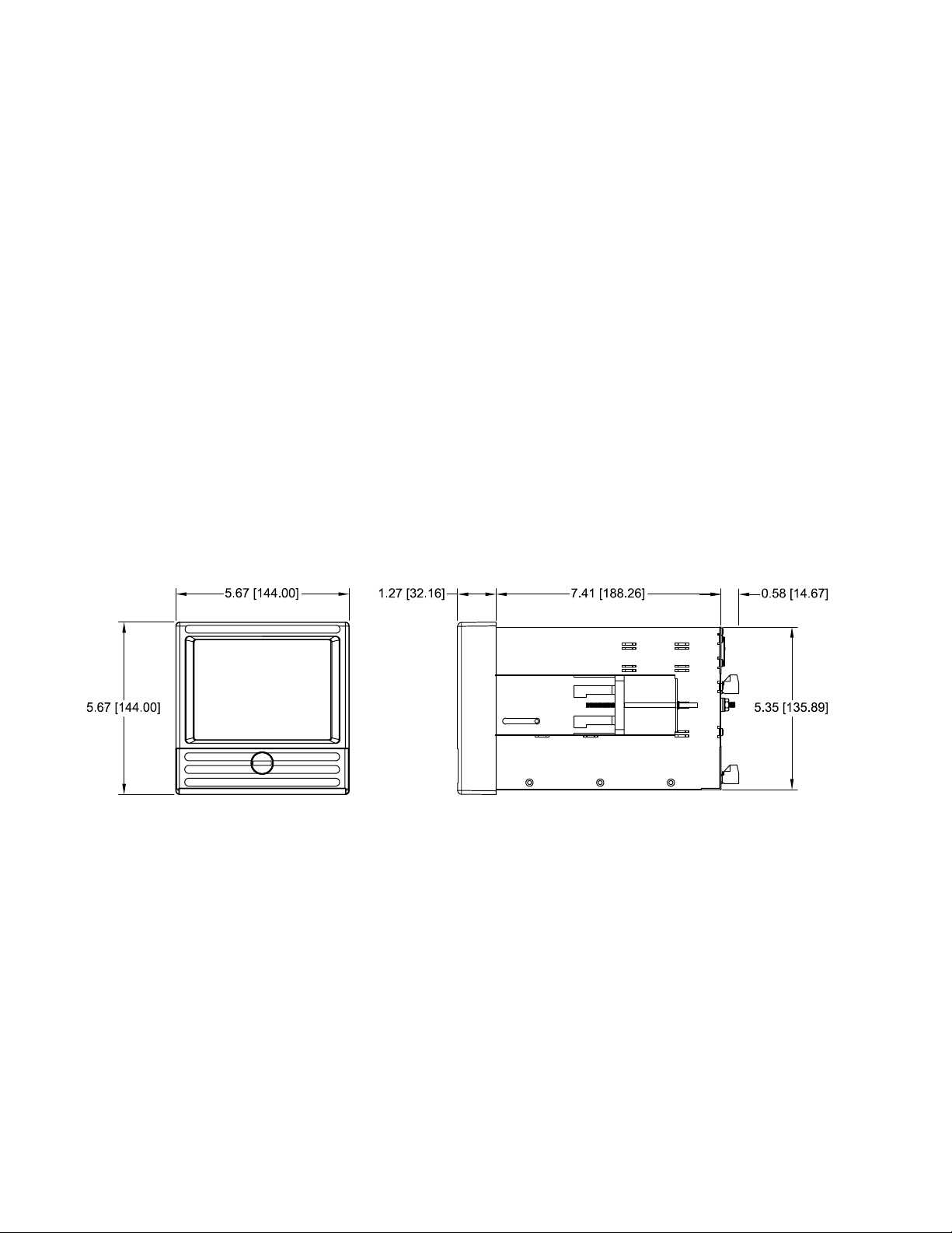
The Recorder is sized to fit in a standard DIN panel cutout of 5.43” x 5.43” [138 mm x 138 mm] and requires 7.41”
[188.2 mm] behind panel depth not including power and input source cable space needed. Actual dimensions are
shown in Figure 2-1.
Figure 2-1 Recorder Dimensions in Inches [mm]
WARNING: Do not use this instrument in any manner inconsistent with these operating
instructions or under any conditions that exceed the environmental
specifications stated.
Page 2-2
Page 21
Chapter 2 Installation and Wiring
2.2.1 Panel Mounting
The Recorder should be mounted in a vertical panel to ensure proper operation. Ensure you have the proper
clearances and proceed as follows:
2.2.1.1 Cut a panel opening 5.43” x 5.43” [138 mm x 138 mm].
2.2.1.2 Remove any packaging material from the Recorder. Always handle the unit carefully to avoid
damaging the LCD display or scratching the display surface.
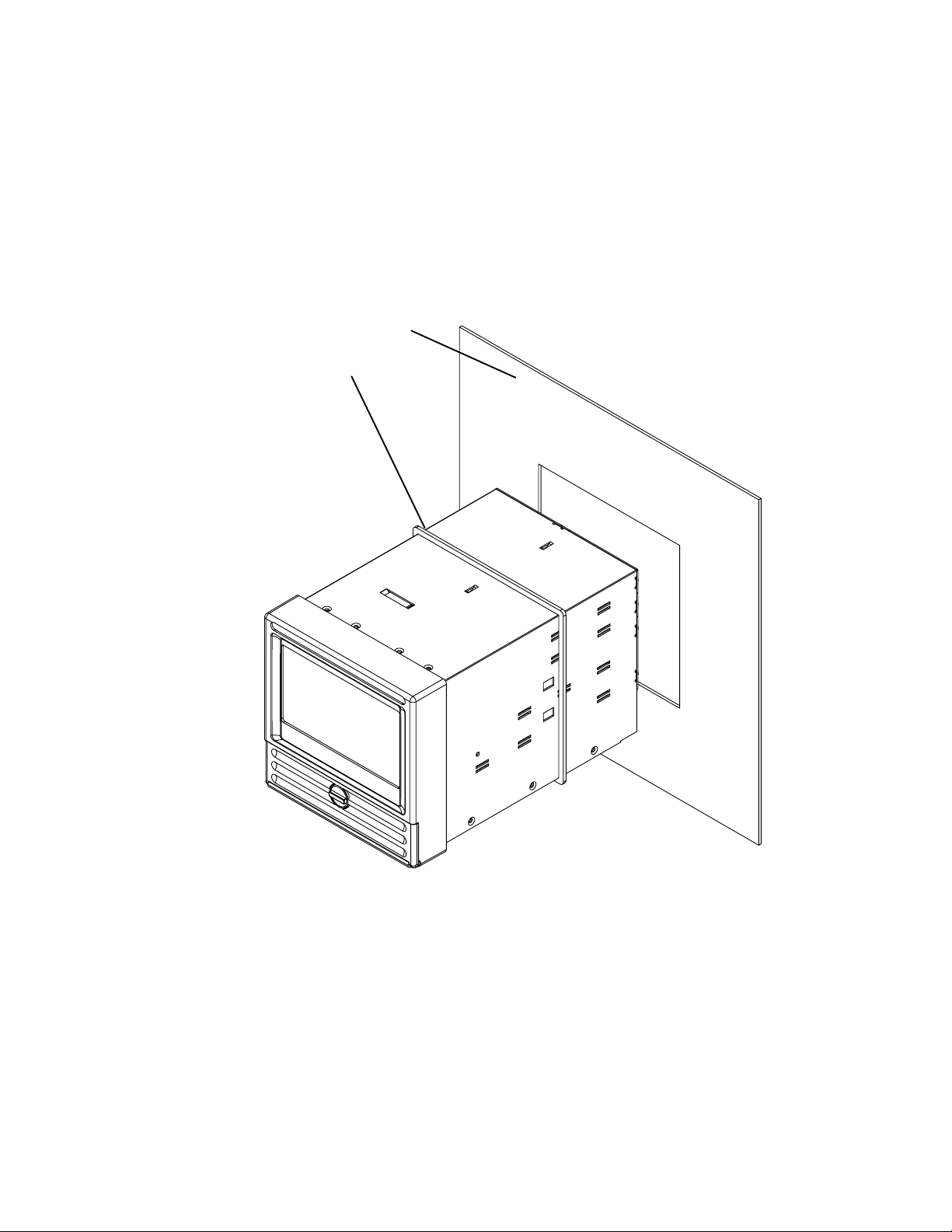
Front Panel
Gasket
Figure 2-2 Front Panel Insertion
2.2.1.3 Remove the locking bars from the Recorder enclosure and ensure the gasket is not twisted on the
enclosure.
2.2.1.4 Insert the Recorder rear end first, into the panel opening from the front of the panel. Ensure the
gasket is between the front bezel of the Recorder and the front panel.
Page 2-3
Page 22

Chapter 2 Installation and Wiring
2.2.1.5 With the Recorder held firmly in place against the panel, install one of the locking bar assemblies
by sliding the locking bar notch into the slot on the side of the Data Chart enclosure.
Rear of Panel
Locking Bar Assembly
Screw
Figure 2-3 Rear View Panel Installation
2.2.1.6 Using a slotted screwdriver, tighten the screw until the locking bar is just pressing against the
panel.
2.2.1.7 Install the other locking bar assembly into the slot on the opposite side of the Recorder enclosure
and tighten as before.
2.2.1.8 Using the screwdriver, tighten both screws so that the Recorder is held firmly in place. Do not over
tighten.
Page 2-4
Page 23
Chapter 2 Installation and Wiring
2.3 Wiring Specifications and Procedures
2.3.1 Power Requirements
The Recorder operates on any voltage from 100 to 240 Vac +10%, 50/60 Hz enabling it to be used in most
countries. The maximum apparent power required by the unit is 35 VA.
2.3.2 Power Connections
NOTE: The recorder is designed to be panel mounted and as such should be considered as
permanently connected. Disconnection from the supply must be possible via a customer supplied switch
or circuit breaker. This disconnection device must be included in the panel installation and should be
clearly marked, in close proximity to the Recorder and easily accessible to the operator.
All connections to the Recorder are made to the Rear Terminal Panel. Any wiring carrying hazardous voltages
must conform to all applicable local and national safety codes. AC Mains connection is via an internationally
accepted IEC 320 AC mains connector or screw terminal (Figure 2-4 and Figure 2-5).
WARNING
Ensure all mains power is turned off before proceeding with installation. This unit
is provided with a mating connector for the ac power socket or with a compatible
three wire grounded cable which may be terminated with a plug. Always ensure
the ground wire (green or green and yellow) or ground pin of the plug, is connected
to a low impedance safety ground (earth) within the ac power distribution system
you are using. Always use the recommended mating connector and an approved
three wire cable to connect this unit to the ac mains. Always provide a low
impedance safety ground wire to the ground lug on the rear panel marked .
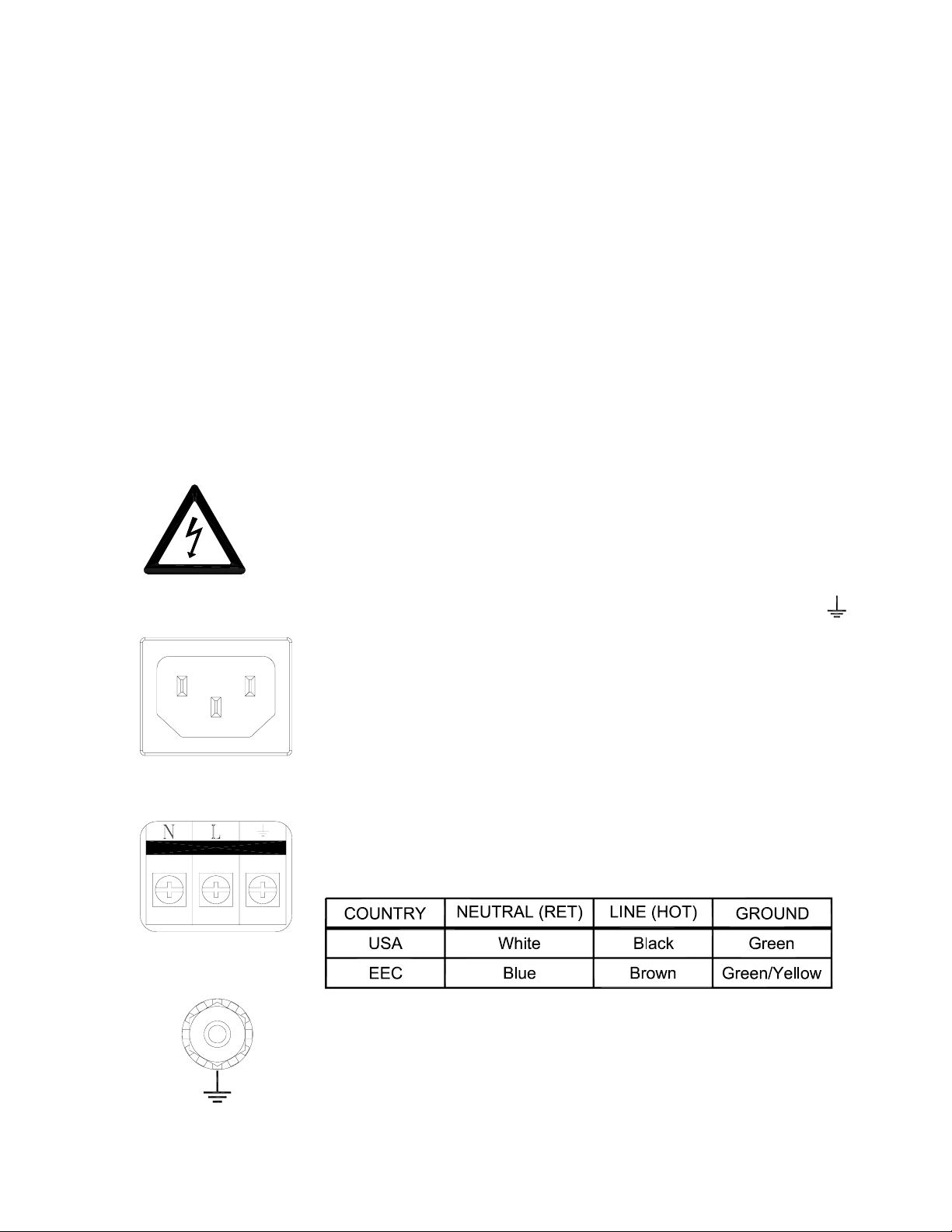
Figure 2-4
AC Connector
Figure 2-5
Screw Terminal
Figure 2-4 shows the IEC 320 AC mains connector on the rear of the Recorder. The
center pin is the ground termination. If a mating plug is provided, it will be marked
with the Ground, LINE (L) or hot, and NEUTRAL (N) or return. In the United
States, an approved cable with integral plug (NEMA 5-15 P) is provided. In some
instances, a cable with no plug may be provided. In this instance, the user must
connect an approved plug to the cable prior to connecting to the AC source.
Figure 2-5 shows the screw terminal power connections on the rear of the Recorder.
The right terminal is ground, the center terminal is LINE (L) or hot and the left terminal
is NEUTRAL (N) or return. The wire color codes are as follows:
Figure 2-5a shows the ground lug on the rear panel. This screw terminal must be
connected to an earth wire which in turn is connected to the ground or earth of the
AC power distrubution system.
Figure 2-5a
Ground Lug
Page 2-5
Page 24
Chapter 2 Installation and Wiring
This unit is equipped with an AC mains fuse internally. If this fuse should blow, it generally indicates a serious
problem with the Recorder. THE FUSE SHOULD NOT BE REPLACED BY AN OPERATOR. The fuse is a
quick acting 5 x 20mm type rated at 2.0 Amps 250 VAC (~).
An optional AC mains plug retention clip is available - contact the factory.
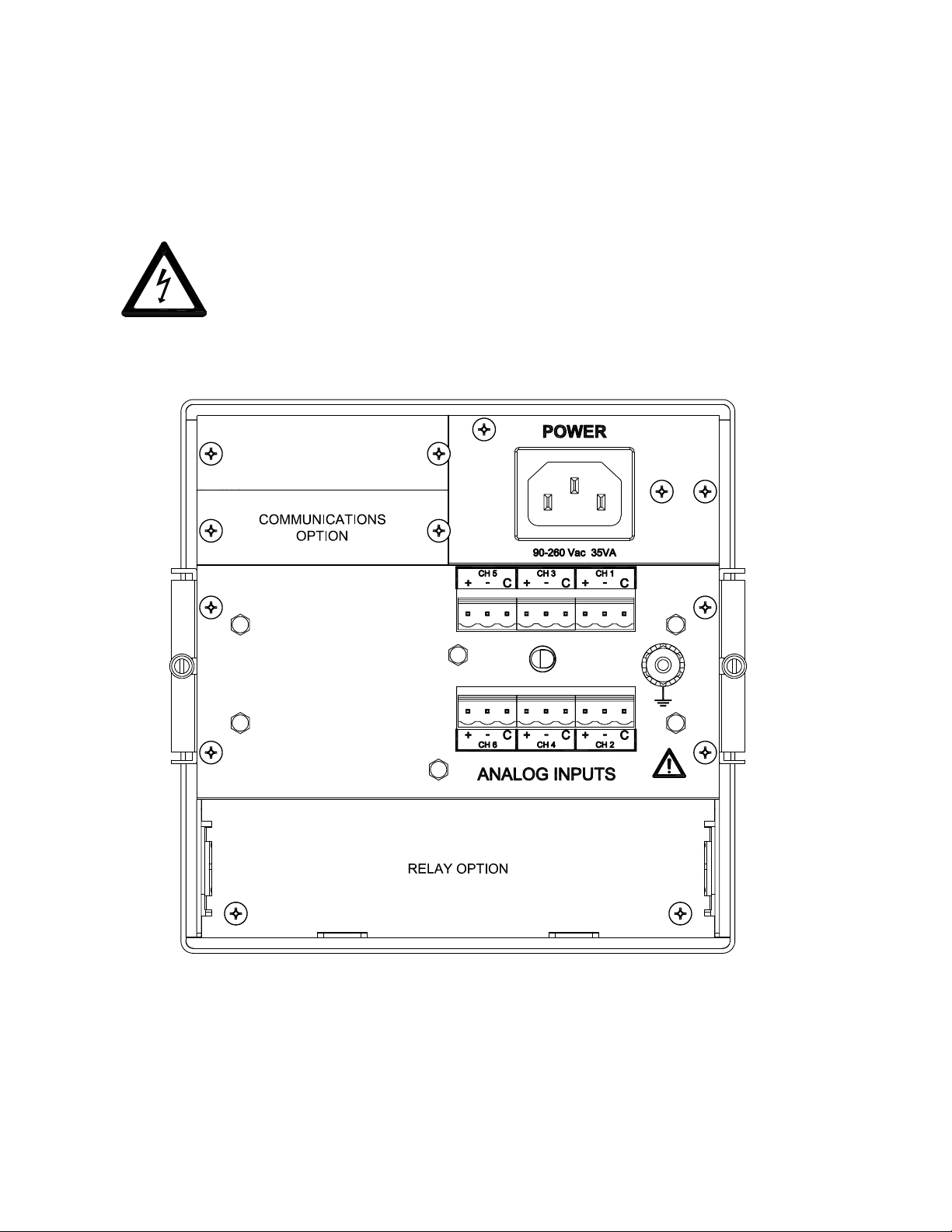
2.3.3 Signal Input Wiring
Signal input connections. Hazardous potentials may exist on signal input terminals
which are floating with respect to case ground. These hazardous potentials may be
on the rear terminal panel of your instrument. Any voltage potential at the signal
source will exist on the instrument’s respective signal input terminal (i.e. power
generator stator winding).
Figure 2-6 DC2000 Rear Panel Connections
Page 2-6
Page 25
Chapter 2 Installation and Wiring
The Recorder accepts up to six direct inputs. Input connection is via plug in screw terminal connectors on the
rear panel. Inputs can be mixed in any combination of thermocouple, RTD, milliamps, millivolts, volts or contact
inputs. There is a common ground lug marked with a
Read the following procedures prior to connecting inputs to the terminals.
WARNING: Ensure the power is off before connecting signal inputs to the unit.
The plug in screw terminal connectors are of the clamping screw variety, putting even pressure on the signal
wire. It is therefore not necessary to terminate the wires with lugs, however you may do so if you wish. The
maximum gauge wire that can be accommodated is 14 AWG or 2.5 mm². You will need a small screwdriver and
a pair of wire cutters and strippers. The use of shielded twisted lead wire is recommended to minimize electromagnetically induced noise.
WARNING: All unused inputs must have all contacts commoned togther.
CAUTION: Never run signal and power or control wiring together in the same conduit. This is to
prevent possible recording error due to induced signals between lines. Route signal
wires away from power wires at the rear panel.
NOTE: Ground cable shields at one end only to eliminate the possibility of interference due to
ground loop currents. When grounded transducers are used, the shield should be grounded
at the sensor end only.
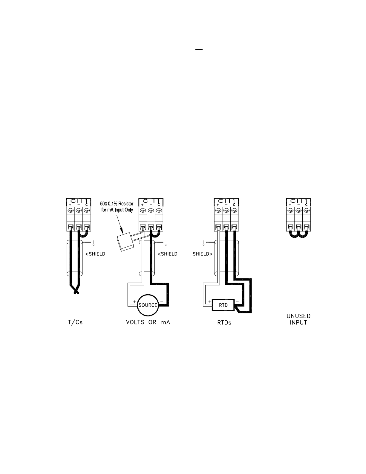
for connection of signal cable shields or screens.
Figure 2-7 Thermocouple, RTD and Linear Inputs
2.3.3.1 Thermocouple Inputs
Thermocouple input connections are made as shown in Figure 2-7 T/Cs. Note that a link must be installed
between the “-” terminal and “C” terminal.
2.3.3.2 Resistance Temperature Detector (RTD) Inputs
Two, three or four wire RTDs may be used for connection with cable compensation of ±50 ohms. Refer to
Figure 2-7 and manufacturing specifications.
2.3.3.3 Linear Inputs
Current inputs: 4-20 milliamps, 0-20 milliamps and 10-50 milliamps, using an external 50 ohm shunt.
Voltage inputs: ±150 millivolts, ±1.25 volts, ±2.5 volts, ±12.5 volts, ±25 volts and normally open/closed
contact inputs. Note that a link must be installed between the “-” terminal and “C” terminal. Refer to Figure
2-7 for details.
Page 2-7
Page 26
Chapter 2 Installation and Wiring
2.3.4 Relay Output, Contact Input
WARNING
To prevent the possibiltiy of electrical shock, use extreme caution when wiring
contact output connections. Hazardous potentials may exist on contact output
terminals which are floating with respect to instrument ground. These hazardous
potentials may be exposed on the rear terminal panel of your instrument. Any
voltage potentials at the contact circuit will exist on the instrument’s respective
contact output terminals (i.e. line-powered circuits).
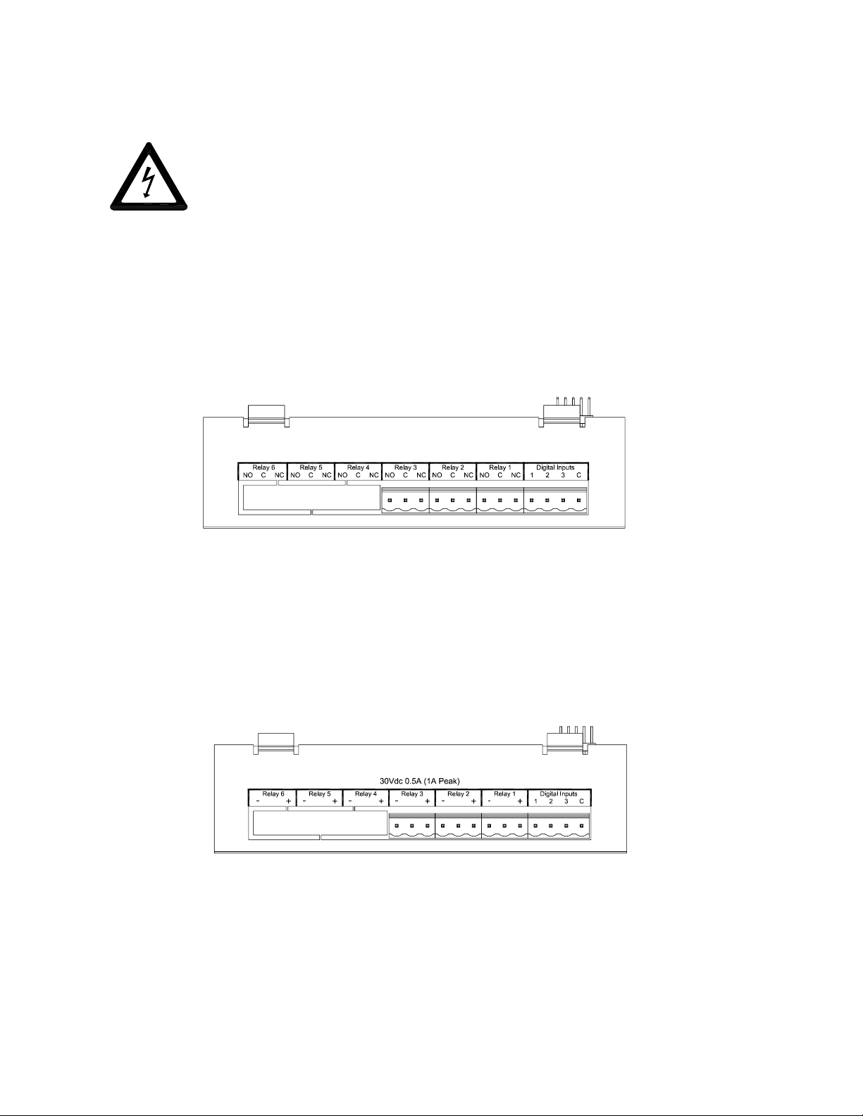
2.3.4.1 Mechanical Relay Option
The Recorder may be equipped with an optional Digital Input Output Board which has three or six potential
free Form C relay contacts and three opto-isolated digital inputs. A terminal block as shown in Figure 2-8
below, is provided for the three alarm output Potential Free Form C connections: Normally Open (NO),
Common (C), and Normally Closed (NC), and the three digital inputs which share a common. The relay
contacts are capable of switching 125 Vac ~ at 0.5 Amp or 30 Vdc at 2 Amps. The potential free relay
contacts are protected internally with 300 volt Metal Oxide Varistors (MOVs) to prevent contact arcing.
Figure 2-8 Mechanical Relay Connections (3 Channel Shown)
2.3.4.2 Solid State Relay Option
The Recorder may be equipped with an optional Digital Input Output Board which has three or six solid
state open collector outputs and three opto-isolated digital inputs. A terminal block as shown in Figure
2-9 below, is provided for the alarm output connections. The output connections are polarized and are
intended for DC operation only. Reverse polarity protection is provided and each output is fused at 1 Amp.
The fuse is solid state and will reverse once the load is removed. The outputs are rated at 30 VDC at 0.5
Amp and are optically isolated from the recorder.
Figure 2-9 Solid State Relay Connections (3 Channel Shown)
2.3.4.3 Opto-isolated Inputs/Outputs
The opto-isolated inputs require an external potential of 5 to 12 volts DC @ 10 milliAmps. The three inputs
are isolated from the unit, but not from each other as they share a common. The positive voltage connects
to the terminals marked 1, 2 or 3 and the common connects to the terminal marked C. It is possible to use
potential free contacts to operate the digital inputs. This requires opening the unit and setting jumpers on
the relay board. Refer to Appendix A for details.
Page 2-8
Page 27

Chapter 2 Installation and Wiring
2.4 Serial Interface Option
Data can be accessed to download Configuration files or Data files using the RS232C option and a modem. The
RS485 option allows the Recorder to be installed into an existing Modbus network or it can be used to connect up
to thirty-one recorders in series. A standard DB9 Female connector is required for the RS232 to connect to an IBM
PC compatible computer using a null modem cable and the RS232 can support cable runs up to 50 feet [16 m]. The
RS485 connection is via two wire (twisted pair) cable (a DB9 Female connector is required) and can support cable
runs up to 4000 feet [1300 m].
The Serial Interface contains an isolated switching unit for RS232 and RS485 access with a standard DB9 Female
connector. When switch 2 is in the ON position, RS485 is enabled. When switch 2 is in the OFF position, RS232
is enabled.
When more than one recorder are connected in a series, it is necessary to apply a termination resistor on the last
recorder. Switch 1 in the ON position applies this necessary termination resistor and should be switched to the ON
position only on the last recorder in series.
SW1
On=485 Term.
12
ON
SW2
On=RS485
Off=RS232
Figure 2-10 RS232/RS485 Modbus
All Serial Interface connections are made through the DB9 female connector.
The RS232 Connection to the DB9 female connector are as follows:
DB9 PIN CONNECTION DIRECTION
2 RxD Receive Data In
3 TxD Transmit Data Out
4 DTR Data Terminal Ready Out
5 Common N/A
7 RTS Request To Send Out
8 CTS Clear to Send In
The RS485 (Half Duplex Mode) Connection to the DB9 female connector are as follows:
DB9 PIN CONNECTION DIRECTION
6 A- Negative Input/Output
9 B+ Positive Input/Output
Page 2-9
Page 28

Chapter 2 Installation and Wiring
2.5 Ethernet Option
The 10BaseT Ethernet option allows direct connection to a LAN or WAN and the standard TCP/IP protocol enables
the transfer of data over the Internet.
Figure 2-11 Ethernet Option
The RJ45 Connection for the Ethernet are as follows:
Receive Differential Pair
3 RX6 RX+
Transmit Differential Pair
7 TX8 TX+
Two LEDs on the rear panel show Ethernet activity. The Link LED indicates a good connection and the RxTx LED
indicates communication activity.
2.6 Cleaning
The unit may be cleaned by wiping with a soft cloth. The front panel and display / keypad may be wiped with a
slightly damp soft cloth containing soapy solution or a mild detergent. Do not use any lemon based (citric acid)
product to clean the display / keypad.
2.7 Contrast Adjust (Monochrome Only)
The contrast or viewing angle of the monochrome LCD display can be adjusted from the side panel. If not
adjusted correctly, the display may look dim, dirty, completely black, washed out or blank. Insert a small star or
Phillip type screwdriver into the hole in the side panel as shown in Figure 2-12 and turn to adjust the display
contrast. The adjustment potentiometer has a 270° rotation. Do not apply excess pressure or attempt to
turn it beyond the end stops.
Figure 2-12 Contrast Adjust
Page 2-10
Page 29

Chapter 3 Getting Started
3.1 Moving About the Screen .........................................................................................................................3-1
3.2 What the Screens Mean ........................................................................................................................... 3-3
3.2.1 Status Line ...................................................................................................................................... 3-3
3.2.2 Disk Status ......................................................................................................................................3-3
3.2.3 Button Bar ....................................................................................................................................... 3-4
3.2.4 Date/Time Window .......................................................................................................................... 3-4
3.2.5 Graphics Window ............................................................................................................................ 3-4
3.2.5.1 Bar Charts.............................................................................................................................. 3-4
3.2.5.2 Digital Windows .....................................................................................................................3-5
3.2.5.3 Alarm/Events Data Window ...................................................................................................3-5
3.2.5.4 Trend Window ........................................................................................................................3-6
3.2.5.5 Transient Windows ................................................................................................................3-7
3.3 Browsing, Compressing and Searching Data ........................................................................................... 3-7
3.3.1 Compressing Data ..........................................................................................................................3-7
3.3.2 Searching Data By Time ................................................................................................................. 3-8
3.3.3 Searching Data By Value ................................................................................................................3-8
3.3.4 Interactive Browse ........................................................................................................................... 3-9
3.3.5 File Browsing ................................................................................................................................... 3-9
3.4 Getting to the Points ............................................................................................................................... 3-11
3.5 Using Chart Scales .................................................................................................................................3-12
3.6 Programming .......................................................................................................................................... 3-13
3.7 Programming Time and Date .................................................................................................................. 3-13
3.8 Programming Points ............................................................................................................................... 3-14
3.8.1 Point tag .......................................................................................................................................3-14
3.8.2 Input Scale ................................................................................................................................... 3-14
3.8.3 Output Scale ................................................................................................................................3-15
3.8.4 Engineering Units .........................................................................................................................3-15
3.8.5 Chart Scale ..................................................................................................................................3-15
3.8.6 Alarms .......................................................................................................................................... 3-15
3.9 Programming Point Scales .....................................................................................................................3-15
3.9.1 Programming Scales ....................................................................................................................3-15
3.9.1.1 Scale Ends .......................................................................................................................... 3-16
3.9.1.2 Scale Units .......................................................................................................................... 3-16
3.10 Recording Data .................................................................................................................................... 3-16
3.10.1 Using the Recorder to format a floppy/zip disk or PCMCIA card ................................................3-17
3.10.2 Selecting the Record Mode ........................................................................................................ 3-17
3.10.2.1 Fill to End ..........................................................................................................................3-17
3.10.2.2 Cyclic ................................................................................................................................3-17
3.10.2.3 Average or Instantaneous Recording ................................................................................3-17
Page 30

3.10.3 Programming the unit for recording ............................................................................................ 3-18
3.10.3.1 Set the record mode ......................................................................................................... 3-18
3.10.3.2 Points ............................................................................................................................... 3-18
3.10.3.3 Record Rate ...................................................................................................................... 3-18
3.11 Hot-Swap ............................................................................................................................................. 3-19
3.12 Changing File Names ..........................................................................................................................3-19
3.13 Setting the Disk Full Alarm ................................................................................................................... 3-19
3.14 Loading and Saving Configuration Files ............................................................................................... 3-20
Page 31

Chapter 3 Getting Started
The Instrument is an extremely versatile solid state data recorder . It has a liquid crystal display capable of complex
graphical representation and either a floppy disk drive, Zip drive or PCMCIA Memory Card for data storage. The unit
is easily programmable and the average user will probably never need to use most of the features or functions
available in the recorder . This chapter will give the user a brief system overview and guide the first-time user
into a simplified setup which will enable you to begin recording with the least amount of effort.
3.1 Moving About the Screen
The Recorder has an LCD Graphics Screen that also acts as a touch keypad. Areas of the screen are active as
push buttons, the exact areas which are sensitive depends on what is currently displayed. The user has only to
lightly touch the screen area depicting the button to activate the function. If the buzzer is turned on, the unit will
provide audible feedback, as a short beep, each time a “button” press is registered. The default display is shown in
Figure 3-1 below.
STATUS LINE
GRAPHICS AREA
4/17/01 15:52:35
Figure 3-1 Recorder Screen
The screen is divided into three distinct areas, the BUTTON BAR, along the bottom of the screen (containing the
time / date stamp), the ST A TUS LINE, across the top of the screen, and the GRAPHICS AREA between the them.
Under normal operating modes, when not in a menu, the BUTTON BAR area is active for “Button” pressing. The
MENU button on the bottom right of the screen, will bring up the command menu button bar, see below, which
allows the user to do a number of functions and select the option of programming the unit. Refer to Chapters 4 and
5 for details.
DISPL
Figure 3-2 The Command Menu Button Bar
Page 3-1
Page 32

Chapter 3 Getting Started
The VIEW button is on the lower left side of the screen, and it enables the user to scroll through the selectable
display options in the graphics area of the screen. These views might be charts, bar graphs, digital or alarm
information. Each time the “button” is pressed, the next view is presented. The Graphics display can be either a full
screen of information, or the screen can be split, allowing combinations of the primary screens to be displayed. The
user can also choose whether the screen is horizontally or vertically oriented.
The area along the top of the display is the Status Bar or Status Line, and it is used to display a number of user
programmed functions such as the unit tag (identification) or the digital values of the various channels or alarm
status. On the right hand side of the Status Line is the disk status information (disk info). This displays the
current condition of the disk that is currently being used to save data. When the unit is not recording, this area
shows REC OFF. When Recording it displays REC
the slow rate, as well as XX% used, where XX is the amount of disk space already recorded. The default display
is set using the DISPL option on the Command Menu button bar. The JOG button is used to switch between
channel data.
To the left of the St atus Line is the position of the ACK button (not shown). This is the Alarm ACKnowledge and
is only present when there is an alarm condition, at which time it blinks until the user presses it to acknowledge
the alarm condition. Pressing the Acknowledge button will also reset any output relays if this option is installed and
programmed. Note that the ACK button will always be the top most button, always rising to the surface when
covered by other items such as menus. The user can thus acknowledge an alarm at any time, even while in the
programming mode.
↑↑
↑ when recording at the fast rate or REC
↑↑
↓↓
↓ when recording at
↓↓
As the user moves through the menu options, more or fewer buttons will be shown. The key buttons are always
displayed on the button bar along the bottom of the display . ENTER and EXIT buttons are always in the same place
on the button bar allowing rapid movement through menus.
The BROWSe button is only displayed on screen views that can actually be browsed. These are the full Chart
Screen and the full Alarm Status Screen. The user can choose to browse RAM (Random Access Memory) which
is the screen trace data, or File, in which case a file menu will be presented so that the user can choose a file from
the disk. The BROWS button also allows the user to SEARCH historic data either by TIME or V ALUE, as well as
COMPRESS data in time.
Pressing the BROWS button puts a freeze on real time display and allows the user to scroll back in time to
browse through historical data that has passed off the screen or has been recorded previously, even on another
machine. The actual Chart Screen browse buffer is dependent on the memory options installed, the number of
traces being displayed and the effective chart speed. With the standard buffer, a chart speed of one inch per
hour with four traces active, it is possible to browse back around 140 hours (5½ days). The user may choose to
browse files on the disk rather than the current memory buffer even though the unit is currently recording. The
user can then browse files that had been recorded earlier, or may even browse the file that is currently being
recorded. Once the data has been recorded to disk, it is possible to use the file browser or the PC and the
companion software to view data as far back as the start of recording, irrespective of how long that may be,
within the constraints of disk capacity.
Page 3-2
Page 33

Chapter 3 Getting Started
3.2 What the Screens Mean
The basic screen layout is shown in Figure 3-3 below. Each area is used to present different information to the user .
3.2.1 Status Line
STATUS LINE
GRAPHICS AREA
4/17/01 15:52:35
Figure 3-3 Basic Screen Layout
The Point information is displayed on the Status line as “ Point No. Value Units” as shown:
The Alarm information is shown on the S t atus line as “Point No. V alue Alarm T ype/Number” where H1 is High Alarm #1. There are 5 possible alarms per channel, H = High, L= Low R = Rate.
If more than one alarm is active they will cycle on the Status Line.
If there are no alarms active the Status Line will show -
The St atus Line is used to show the Unit Tag, Point information, rear terminal Junction Temperature or Alarm information.
The choice as to what is transiently displayed is set in the
DISPL menu (Chapter 4.2.1) or the user can set the default
display for this line in the “PROGram - Display - Powerup disp”
menu (Chapter 5.4.3). At any time the user can press the JOG
button to display point data on the Status line. Each time JOG
is pressed the next point data will be shown. The data can be
set to auto jog from the “PROGram - Display - Powerup disp
- Autojog” menu (Chapter 5.4.3.2).
1 0.496 VOLTS
NO ALARMS
1 0.496 HI
The Unit T ag is shown on the S tatus Line and may be up to 20 characters long. It is entered from the “PROGram Display - Powerup disp - Unit T ag” menu (Chapter 5.4.3.1) and displays as entered -
This is a UNIT T AG
3.2.2 Disk Status
The area in the top right corner marked DISK ST A TUS is used to show Disk S t atus. The following messages
may appear in this area:
OFF 15% Unit is not recording to disk. Record Mode is OFF - Disk is 15% full.
↑↑
REC
↑ 15% Unit is recording to Disk in HIGH speed mode - Disk is 15% full.
↑↑
↓↓
REC
↓ 75% Unit is recording to Disk in LOW speed mode - Disk is 75% full
↓↓
FORMAT Disk is being Formatted
SAVE CFG Saving Configuration to Disk
LOAD CFG Loading Configuration from Disk
TRIG 75% Unit is waiting for an Event or Alarm to turn the Record Mode on - Disk is
75% full.
Page 3-3
Page 34

Chapter 3 Getting Started
3.2.3 Button Bar
The Button Bar is the area across the bottom of the screen where the main menu buttons appear. The function
of these buttons varies according to which mode is selected for the unit. Figure 3-3 shows the Normal mode
button layout.
3.2.4 Date/Time Window
The Date /Time window sits at the bottom of the screen in the Button Bar and continuously shows the current
date and time. Date is shown numerically in either American Month/Day/Year or European Day/Month/Year
format. The format is selected in the “PROGram - Display - Time format” menu (Chapter 5.4.2)
3.2.5 Graphics Window
The graphics window is used to display various information in different formats. The VIEW button is used
to switch between the various graphic displays which can be Trend Charts, Bar Graphs, Digital Windows
or Alarm/Event data, or combinations of these. Furthermore the graphics can be horizontally or vertically
oriented. The orientation is selected in the “PROGram - Chart/Pens - Direction” menu (Chapter 5.5.4)
3.2.5.1 Bar Charts
Bar graphs can be displayed on their own or as part of a split screen. Up to
twelve can be displayed at a time. The user can select to display bar graphs
either horizontally or vertically . The assignment s of points to bar graphs is made
in the “PROGram - Display - Bar assign” menu (Chapter 5.4.4). The format of
the vertical bar graph is shown opposite in Figure 3-4. The very top of the bar
has the actual/real time digital value of the point, in this case 0.385. Immediately
below this is the Engineering Units shown as ENG UNITS. There can be a
maximum of five characters. At the very bottom of the bar graph is the POINT
T AG. This is a ten character description of the point.
Figure 3-4 Bar Chart
NOTE: Not all characters can be displayed on the bar graph.
Between the ENG UNITS and POINT TAG is a bar that represents the actual
value as a function of the full scale value. To the right of the bar are scale values.
The alarm setpoints, if any are set, are indicated on the bar by a “ W “ in the text
area. If any alarm is active, the bar will be blinking. The Engineering Units, Point
Tag, alarm setpoints and scaling of the bar is done in the “PROGram - Points”
menu (Chapter 5.6)
Page 3-4
Page 35

Chapter 3 Getting Started
3.2.5.2 Digital Windows
Figure 3-5 Digital Window
3.2.5.3 Alarm/Events Data Window
Digital Windows can be displayed on their own or as part of
a split screen. Up to twelve can be displayed at a time. The
assignment of points to digital windows is made in the
“PROGram - Display - Digital assign” menu (Chapter 5.4.5).
The format of the digital window is shown opposite in Figure 3-5. The large numbers in the center of the window are
the real time point value. Above this point value is the Point
T ag shown as POINT TAG. This is a ten character description of the point. Below the point value is the Engineering
Units shown as ENG UNITS. There can be a maximum of
five characters. The Engineering Units, Point Tag, and scaling of the digital value is done in the “PROGram - Points”
menu (Section 5.6).
Alarms/Events Data Log
Alarm Checks On
Date Time Point Status Value
07/20 13:10:37 POWER UP
07/28 14:58:56 Pt 1 HIGH1 0.504
07/28 14:52:09 Pt 1 * 0.492
07/28 14:51:33 Pt 5 FALSE 0.000
07/28 14:45:00 Pt 6 HI Reset 17.427
07/28 14:35:27 Pt 6 Hi Peak 23.568
07/28 14:40:15 Pt 1 HIGH1 0.504
07/28 14:22:56 Sw 1 CLOSE
07/29 07:34:28 POWER DOWN
Figure 3-6 Alarm/Event Window
The format for any entry in the Alarm/Event file is - Date T ime Point S tatus V alue. The Point value is
shown as Pt X, where X is the point number. The Value shown is dependent on the Event. The Event can be
an Alarm, an input cont act closure (event) or a reset, either automatic or manual.
For linear inputs, the alarm event description is HIGH1 or LOW2, where the number is the alarm count up
to a maximum of 5. For conditional inputs, the alarm event descriptions are OPEN, CLOSE, TRUE or
FALSE. The value is the actual value at the time the alarm was registered. An event message of “*” is an
alarm return to normal condition, the time the point came out of alarm.
The alarm/event window is used to display
alarms, events, reset, power up and power
down information. This data may also be
recorded to disk by enabling Alarm data
in the “PROGram - Disk functions - Alarm
on/off” menu. (Chapter 5.7.2).
The second line of the display indicates the
status of the alarm checking. If alarm checking is enabled this will indicate ‘Alarm Check
On’ or it will indicate ‘Alarm Check Off’ in
which case no alarms will occur.
The state of alarm checking is changed in
the “FUNCtion - Alarm Check” menu (Chapter 4.2.3.7).
Resettable points, such as totalizers, will show the event as RESET, with the actual value at the time of
reset. Some Resettable point types, such as HI PEAK will have two entries (Pt 6 above). The first entry is
the date and time that the high peak occurred, with the peak value, the second entry , above it, is the actual
time the reset occurred, with the value at that time. Note: Resettable points will not print unless the Reset
Print option is turned on in the “PROGram - Points” menu (Section 5.6)
For external events via the digital inputs, the user can define separate messages for each of the three
inputs, one for input activated (Close) and one for input deactivated (Open). These event messages
can be entered, up to a maximum of ten characters, in the “PROGram - Digital I/O - Event msgs” menu
(Chapter 5.9.3). This message will appear in the log as - date - time - Switch number (Sw X) - Event
message. Default event messages are CLOSE and OPEN as seen in the data log example above.
Page 3-5
Page 36

Chapter 3 Getting Started
3.2.5.4 Trend Window
The trend window is the one that looks like a “paper” recorder. It has traces or pens and emulates the p aper
chart, moving the “paper” across the screen, and is shown in the vertical mode in Figure 3-7 below. The
direction of the trending can be vertical, from top to bottom, or horizontal, from right to left. The direction
can be changed in the “PROGram - Chart/Pens - Direction” menu (Chapter 5.5.4). There may be as many
as twelve pens on the chart at a given time. Pens are assigned to the chart in the “PROGram - Chart/Pens
- Pens” menu (Chapter 5.5.3).
Consider the vertical chart below, the same features are found on the horizont al chart. Along the top of the
chart are the pen pointers, one for each pen that is on. These track the real time value of the points and
identify the origin of the trace.
S S
Figure 3-7 Vertical Trend Window
There are grids on the screen, both horizontal and vertical. In the above example, the vertical grid spacing is a
function of the divisions on the chart scales. The horizontal grid lines indicate the scales for the chart, and if
there is more than one scale set, they alternate. On the full screen trend view, the scales can be toggled through
by pressing the middle of the scale (top center of the display). Each scale has its end points marked along the
top of the chart with the scale value, the 0.00 and 1.00 indicating that the trace has a value of zero when it is
hard to the left, and 1.00 when it is hard to the right. There is a marker on top of the pen pointers to indicate
which pens reference the current scale. Thus when interpreting the data for pens 1 and 2 use a value of 0 to
1.00 full scale. When the scale changes, so will the markers on the pen pointers to indicate the pens for the
next scale. Also along the top of the chart are the scale UNITS.
Page 3-6
Page 37

Chapter 3 Getting Started
3.2.5.5 Transient W indows
Transient windows are those that appear momentarily . They pop
up over any existing window to inform the user of a problem
or of a background task being completed. They require a user
response, normally pressing the “OK?” button, to acknowledge
the message.
Figure 3-8 Transient Window
3.3 Browsing, Compressing and Searching Data
Once at the full trend screen (using the VIEW button), the user can choose to browse, search or compress either
data from the disk, including the file currently being recorded to disk, or immediate past data which is buffered to
memory (RAM). The operation of browsing is the same whether the user is browsing memory or file data. When
BROWS is pressed a new button bar is presented with three buttons, FILE , RAM and EXIT as shown in Figure 39 below.
4/17/01 15:52:35
Figure 3-9 The Browse Source Button Bar
Select FILE to browse prerecorded files on the disk, RAM to browse Trend data from memory , or EXIT to return to
the real time view.
Browsing allows the user to view historic data of the pens currently trending on the display or saved on the disk,
without affecting any real time data acquisition. Alarm data can also be browsed from memory by selecting BROWS
on the full view Alarm window . See section 3.3.5 for the added step required to browse from disk.
On the Trend screen, pressing BROWS brings up the Browse Source button bar . Press RAM to browse memory or
FILE to browse from disk. This brings up the Browse Mode Button Bar shown below (Figure 3-10).
Figure 3-10 The Browse Mode Button Bar
The FINDV and the FINDT buttons initiate the SEARCH functions. FINDV is FIND by
Time. The “ÎÍ“ and “ÍΔ are to COMPRESS and EXPAND data respectively. BROWS enters the interac-
tive Browse Screen and EXIT returns to the prior screen.
V alue, FINDT is to FIND by
3.3.1 Compressing Data
The data on the screen may be compressed up to 32 times the normal view , this enables long term trends to
be seen on a single screen. Each time the “ÎÍ“ (Compress) button is pressed the data is compressed by a
factor of 2, and it may require a short time for the recorder to process the data. Five presses give the maximum
32 times compression. The data may be expanded back by pressing the “ÍΔ (Expand) button. The user can
enter the interactive browse mode with any level of compression by simply pressing the BROWS button.
Page 3-7
Page 38

Chapter 3 Getting Started
3.3.2 Searching Data By Time
The historic data can be searched by time, by pressing the FINDT (FIND Time) button. This will bring up a
transient window showing the time to be searched. If the displayed time is correct press ENTER, if not press
NO. This will bring up a series of windows to allow the required time to be entered. The Date will then be
displayed. Press NO to change or ENTER to accept. The data will be searched and the sample corresponding to the required time and date will be placed under the cursor near the center of the screen. The search
may take some time, especially if searching a large disk file. If no point is found the unit will display “No
Point Found”. The user can then enter the interactive browse mode by pressing the BROWS button.
3.3.3 Searching Data By Value
The historic data can be searched by value, by pressing the FINDV (FIND Value) button. This will bring up
the Search V alue button bar shown in Figure 3-1 1 below.
Figure 3-11 The Search Value Button Bar
T o set up the actual Value to search for, press the VALUE button. Use the numeric keypad to enter the value
to search for. Note that you cannot search for an exact match, you will be looking for a value immediately
greater than or less than the value you enter. Once you have entered the value you want, press the ENTER
button.
Before you begin a search, you have to decide which PEN or point to use as the search reference, and which
direction to search in.
Use the PEN button to select the pen trace to search. Each time this button is pressed, the next pen is
selected. The current pen is shown in the status line at the top of the screen, together with the value of the
trace under the cursor and its actual time and date stamp.
The search direction is determined by the button to the left of the PEN button. This button toggles between
BACK and FWD. BACK will search BACKWARDS in time from the current cursor position (into older data),
while FWD will search FORWARDS in time from the current cursor position (into newer data).
To initiate a search press either the FIND> button to find the first point GREA TER than the search value, or
FIND< to find the first point LESS than the current search value. Each time either of these buttons is
pressed, the next point that meets the search criteria is found. Note that once a point is found, the next point
to be found will be the one that is after the first point that does not meet the criteria. The search “hops”
across all other values so that you are not bogged down finding useless information. Therefore if you are
searching for a point on a sine wave, for example, you will find the same point on the same phase of the
wave (360° apart). Otherwise you would find every point less than or greater than the search point which
could be every point in the trend.
The point that meets the search criteria will be placed under the cursor near the center of the screen. The
search may take some time, especially if searching a large disk file. If no point is found the unit will display
“No Point Found”. The user can continue to search for other points in the same direction or change direction
and search again. Once an acceptable point is found, the user can enter the interactive browse mode by
first pressing the EXIT button to return to the Browse mode button bar and then pressing the BROWS button.
Page 3-8
Page 39

Chapter 3 Getting Started
3.3.4 Interactive Browse
The interactive browse mode enables the user to uniquely identify points on the screen by time, date and value,
and move around in time. Once the Browse source has been selected, FILE or RAM, pressing the BROWS
button again, immediately or after a search or compress operation, will enter the Interactive Browse mode, and
the Browse Button Bar shown in Figure 3-12 below will appear.
Figure 3-12 The Browse Button Bar
The cursor appears near the center of the screen. It can be moved with the UP Arrow and the Down Arrow keys
in the Vertical mode, or with the Lef t Arrow and the Right Arrow keys in the Horizont al mode. Pressing these
keys a single time, moves the cursor one sample at a time, holding these keys will cause the cursor to move
in 10 sample increments. As the cursor moves, the time and date information is updated in the status window
at the top of the screen. T o move about more speedily , the PAGE- and PAGE+ buttons move the data forward
or backward an entire screen at a time.
When browsing graphics, the Status Bar at the top of the screen shows the Date and Time stamp and actual
value for the trace data directly under the cursor . Note that if you are browsing Memory there will be an “M” in
07/27/96 17:03:06 point 1: 0.318 Volt s F
the right hand corner of this line or if browsing Files, there will be an “F” as follows:
T o see the actual pen data value press the PEN button to toggle the dat a through each trace if more than one
trace is displayed. As the data is toggled, the traces for all pens but the selected one, disappear. Press EXIT
to return to real time viewing from the RAM browser or to the directory from the FILE browser.
3.3.5 File Browsing
File Browsing can be done at any time, note however that if you are browsing from disk while recording,
there may be delays in retrieving data from the disk as writing to disk has priority over reading from disk.
Press BROWS to bring up the Browse Select Button Bar and choose FILE, to browse files from the disk.
Note: Ensure that a disk is present and that it has suitable files or you will get an error message.
Once FILE has been pressed the unit will check the disk then bring up a directory . If there is more than one
file per point, the files for that point will be displayed one under the other with an “<” indicating the current
file selected as shown below. The list will scroll if it is longer than what will fit on the screen.
Page 3-9
Page 40

Chapter 3 Getting Started
File Directory
Point: 1
BATCH1 .DT1<
BATCH2 .DT1
BA TCH3 .DT1
If only one file is available per point, the directory selection will default to that file, if no files are available for that
point, the directory will indicate “No Files Found”. Use the POINT button to select the point you want.
Once you have the directory listing of files for the specific point, use the
keys to select the file you wish to browse, indicated by the “<” mark. Press the ENTER button to browse the
selected file. Once the file is loaded, it is browsed, compressed or searched in the same manner as the
memory browser described above. Press EXIT to select a different file or EXIT again to return to real time
viewing.
This space intentionally left blank.
ÏÏ
Ï (UP Arrow) and
ÏÏ
ÐÐ
Ð (Down Arrow)
ÐÐ
Page 3-10
Page 41

Chapter 3 Getting Started
3.4 Getting to the Points
The Instrument is a 15 point recorder of which up to 6 channels may be direct or real world inputs. These are
typically voltages or currents. Any channel not being used to record or display live inputs may be used as a
computational channel. Inputs can be conditioned or scaled to display any range of engineering units. Refer to
Figure 3-13 below.
Figure 3-13 Data Flow
There are four distinct levels of data handling, namely conversion, conditioning, scaling and display/record. Conversion applies only to live inputs and is the process of converting real world analog signals into a 16-bit digital value
that can be used by the Recorder. There are five full-scale ranges for all conversions, 150 milliVolt s, 1.25 V , 2.5 V ,
12.5 V , 25V , and DC. The converted values p ass to a conditioning block which converts the binary value which is
effectively a percentage of full scale, into a value useful to the user. Conditioning includes converting the binary
value into a representative voltage, conditioning and linearizing this voltage to represent for example, a real world
temperature as might be input by a thermocouple or RTD, and applying any other computation as required. The
conditioning block handles 15 channels. The outputs from the conditioning block are referred to as base points
and may be fed back to the inputs of the conditioning block to form the basis (base point) for other base point
computations. This includes tracking peak or valley values, doing moving averages, timed averages, difference,
totalization or any other user-entered equation.
Page 3-11
Page 42

Chapter 3 Getting Started
The input to any channel in the conditioning block can be any one of the base points, or it can be the live inputs.
Live inputs can have input and output scaling applied in the conditioning block unless this is predefined by the
nature of the input, i.e., thermocouples. An example of input/output scaling is given in section 3.5.
The outputs of the conditioning block are also the values represented in the Digital Windows and are real-world
engineering values. The outputs of the conditioning block are also fed through to a scale block where a chart
scale is applied to each point. The chart scales determine what part of the full scale range will be used by the
display/record block. There are two sets of 8 scales available to the user . The second set is an alternate set which
can be applied to the base points in place of the normal set when triggered by an external event. Each chart scale
may be applied to any one or more of the base points to provide an output scaled point. These scale points are
then applied to the display/record block which consists of the visual information or recorded information that the
user requires. Up to twelve scaled points are applied to the bar graph display . Up to twelve may be displayed on the
chart and up to fifteen may be recorded to disk. Note that points recorded to disk need not be the same as points
displayed on the bar graph or the chart, however, in the case of the chart, any point which is not recorded to disk will
have limited browse capability . The user should also be aware that applying scaling other than full scale output to
recorded data, limits the data to the range between scale endpoints. It is possible to store the base point with
different scaling than is used to display it on the chart using one of the computational channels.
3.5 Using Chart Scales
T o better understand the use of input and output scaling, and how scaling base points af fects the data, consider the
following example, highlighted by Figure 3-14.
Figure 3-14 Scaling Example
Assume the user wants to record the output from a pressure transducer which gives a 0 to 5 volt DC output signal.
This coincides to a pressure of 0 to 3000 pounds per square inch (PSI). The process being monitored typically runs
at 2200 PSI ±10%, this is the area of interest. The output of the transducer which peaks at 5 volts is connected to
live input channel 1 and the 12.5 volt full-scale range is selected to cover this range. Since the maximum input
voltage will be only 5 volts on a 12.5 volt range, use the input scale option to set the low end at 0.0, and the high
end at 5.000 volts. To convert this directly to PSI, the output scale is set at low point 0.0 and high point 3000.0.
The base point now becomes 0 to 3000 for an input of 0 to 5 volts, scaled linearly across the range. The engineer-
ing units can be set to PSI and the point tag can be set to any label that identifies the process. All of this is
accomplished in the Points menu - Section 5.6. Apply scale A to the base point, this too is selected in the Points
menu.
Page 3-12
Page 43

Chapter 3 Getting Started
It is then necessary to define chart scale A to suit the requirement - Section 5.5.2. In order to maximize the
display resolution, the user is interested in pressure ranges from 2000 to 2500 only . Scale A is thus set for a low
end of 2000, a mid-range of 2250 and a high end of 2500. This scale point is now assigned to the bar graph and the
chart graph. The chart will thus display from 2000 to 2500 as will the bars, maximizing the display resolution for the
value of interest. The user can choose to record this particular value, in other words, what you see on the chart is
what is recorded to disk, values from 2000 to 2500. Or, if so desired, the user can choose to record a second point
which will show pressures from 0 to 3000. To do this, use the channel 1 as a base point for a computational
channel and multiply this value by 1 which is then recorded to disk.
3.6 Programming
While the unit may be programmed remotely, this exercise deals with manually programming the unit from the
front panel using the display and the touch screen keypad. Various buttons and keys will be presented on the
display. The user simply makes a choice by pressing the appropriate key or button. In some instances, direct
selection is not possible but rather a series of choices is made by using an UP or DOWN arrow button, pressing
ENTER or EXIT. Once programming is complete, the unit automatically LEARNS the current setup which is
stored in nonvolatile memory and remembered indefinitely.
When powering up the unit for the first time or if the data in the nonvolatile memory should become corrupt, the user
will be asked to perform a Smart Initialize, select No. The user will then be requested to perform a full initialization.
Select Yes at this stage to reset all values to the default.
There are many parameters that can be programmed, including time and date, the display, the virtual chart and
pens, the points, the recording capability, the alarms, the digital outputs and the communication port.
3.7 Programming Time and Date
Begin by programming the time and date. To enter the program mode, press the MENU button displayed in the
bottom right corner of the screen. This will bring up the Command Button Bar. The Status Line may display
“Command?” or any other preprogrammed item that the user has chosen. To enter the Programming mode,
push the PROG button which will bring up the Program menu. The user can navigate about this menu by using
the UP and DOWN arrow keys to highlight the menu choice and then pressing ENTER. Note that as a choice
scrolls off the bottom of the menu, it reappears at the top. This is a quick way of getting around the choices.
Some buttons also auto repeat. At any time, the user can exit from the menu by pushing the EXIT button as
many times as it takes to return back to the display screen.
Use the UP and DOWN arrows to select the Time and Date menu choice then press ENTER. The current time
will be displayed in 24 hour format. If the time is correct, you may choose not to program the time by pressing
YES or ENTER to accept the current time. To change the time, press NO. You will be presented with the hours
menu and a numeric keypad which will enable you to enter the current time in hours. Use the LEFT and RIGHT
buttons to move the cursor to the digit you wish to change or simply enter the hours using the numeric keys. Use
the SPACE button (SPC) to clear any digit. Once you have selected the correct number of hours, press
ENTER. Note that you cannot enter an illegal value. Once the hour has been programmed, the minutes
menu will be presented. This will then be followed by the seconds menu once the minutes have been programmed.
Once the time has been programmed, the date is presented. To change the date, select No. T o accept the date,
select Yes or ENTER. Once the date has been programmed or accepted, you will be returned to the Program
menu.
Page 3-13
Page 44

Chapter 3 Getting Started
3.8 Programming Points
The points are the input or calculated channels that are assigned to the display or are recorded. In case there is
any incorrect point data stored, clear all points before reassigning them. To do this, get to the Hidden menu (Press
MENU then the upper right-hand button (disk status area)). Select Initialize then press ENTER and then using
the UP and DOWN arrow keys select the Clear Points menu option by once again pressing ENTER. Y ou will then
be asked whether or not you wish to “clear?” the points. Select Yes which will return you to the menu. Press EXIT
twice to return to the Programming menu.
From the Program menu, select Points and press ENTER. You will be given the option to either program points
(Prog point) or program constants. Select Prog(ram) Point and press ENTER. You will be presented with an
alphanumeric keypad and will be prompted for which of the twelve possible points to program. Select 1 and
press ENTER. The Point s Program menu will be presented. You can choose to either set up a point “Setup pt”,
copy the data from another point that has already been set up “Copy pt”, or restore the original data you just
removed “Restore Pt”. Select “Setup pt” and press ENTER. You now have a selection of various ways in
which this point can be programmed. These include Linear, Industrial square root “Ind sqrt”, Log linear,
thermocouple “T/C”, RTD, Calculated, Conditional, or External. Program this point as a Linear point by selecting
Linear from the menu and pressing ENTER. Y ou now have to choose the full scale input range for this point. Note
that when this point is programmed as a milliamp input, it is necessary to set the switch for that channel on the rear
panel to connect in the terminating resistor that allows the current to be measured as a voltage input. Read chapter
5.6 for more detail. Program this point for one volt full scale input by using the UP and DOWN arrow keys to select
“1.25V” and pressing ENTER. Y ou will now be presented with a menu that enables programming of various options
pertaining to this particular point in the one volt full scale mode. These include the Point tag, Input scale, Output
scale, Engineering units, Alarms and Chart scale. Refer to the det ailed chapters for those items not covered below.
3.8.1 Point tag
This is an alphanumeric indication of what the point represents and is generally located or displayed at the
bottom of the bar graphs or on the chart itself. This information is also stored to disk to uniquely identify the
point. To add a point tag, select this option and press ENTER. You will be presented with the first page of
an alphanumeric keypad. There are four pages available which includes all the upper and lower case
alphabet characters, numerics and various signs and symbols for programming engineering units. Up to ten
characters for the point tag may be entered (only six will be displayed on the screen). To access characters
on another page, simply press the PAGE button. The space is ‘SPC”, the LEFT and RIGHT arrows move
the cursor to the position you wish to edit or enter. You may exit this menu choice without programming
a tag or, once programmed, press ENTER to return back one menu with the tag in place.
The way data is displayed on the chart or recorded to disk is a function of three things: the input scale, the
output scale and the chart scale. These may be programmed independently to provide a full scale output of
any range of the input.
3.8.2 Input Scale
Select Input scale from the menu and press ENTER. Y ou will be presented with the value to represent the low
or bottom end of the input scale and for this range, it will default to 0. Up to thirteen characters can be entered.
The number can be in floating point format using the E Key. It may be positive or negative, right or lef t justified.
For our programming example, accept 0 as the low end and press ENTER. Y ou will now be presented with the
option to program the high value. This value will default at 1.25. For the sake of our exercise, enter 1.0 and
press ENTER.
Page 3-14
Page 45

Chapter 3 Getting Started
3.8.3 Output Scale
The output scale is the value that will be reflected on the display or recorded to the units and will once again be
scaled by using the chart scale programmed at a later time. Select Output Scale by pressing ENTER. What
we will do is program this to be 0 - 100. This first option presented is to select the number of decimal places
that will be presented. This varies from 0, which is a whole number , through to 5, which is E notation. Use the
UP and DOWN Arrow Keys to select three decimal places and press ENTER. Once selected, you will be
presented with the value for the low end of the output scale. This will default to 0, select this value. Y ou will now
be presented with the high value which defaults to 1. Use the RIGHT Arrow Key to move the cursor under the
decimal point then press 0 twice and the period or point once so that you have 100.0 on the display, then press
ENTER. Y ou have now effectively programmed the output scale to represent 100 times the input scale.
3.8.4 Engineering Units
At the program menu, use the UP or DOWN Arrow Keys to select Engineering Units and press ENTER.
You may enter up to five characters representing the Engineering Units using the alpha numeric keypad in
the page mode as done for the point tag. We will use percent as the Engineering Units. Press the Page
button three times until you see the ‘%’ (percent) sign. Press the ‘%’ (percent) button and press ENTER.
We have now programmed the Engineering Units to percent.
3.8.5 Chart Scale
To finalize the display scaling, we need to set the chart scale. Select this option from the Program menu Chart/Scales - Scales, and you will be offered a choice, Chart Scale = A by default. You can select one of
eight scales numbered A - H by using the UP or DOWN Arrow Keys. For the sake of this example, select
B as the chart scale to use and press ENTER. You will be returned to the Programming menu. The actual
chart scale is programmed elsewhere and is covered in Section 3.9.1.
3.8.6 Alarms
There are five alarms associated with each point and these can be programmed using the Alarm menu.
Select Alarms and press ENTER. At this point in time, we are not going to spend any time on programming
the alarms. You may browse through it to see the capability of the instrument. Programming alarms is dealt
with in Section 5.6.5.10. Note that in order for Alarms to be active, the user has to enable Alarm checking in the
FUNCtion Menu. Press Exit to return to the Programming menu then press Exit one more time to exit the
Programming menu. You will be asked whether or not you wish to keep Setup. Answer yes at this point in
time to load the values into the system.
3.9 Programming Point Scales
See also Section 5.5.2. From the Programming Menu use the UP or DOWN Arrow Keys to select the Chart Pens
programming option.
3.9.1 Programming Scales
Select the Scales option. Here you can program to Chart scales. Two set s of eight scales are available - Set
‘1’ labeled A - H and set ‘2’ labeled A - H. The exact details are covered in Section 5.5.2. Right now we wish
to program the scale that we assigned to the previous Point 1 we have just programmed. Use the arrows to
select the scale 1B then press ENTER. Y ou are now presented with a menu which enables you to program the
scales. The scale type can be programmed logarithmic or linear and defaults to linear which we will accept.
Page 3-15
Page 46

Chapter 3 Getting Started
3.9.1.1 Scale Ends
Use the arrow keys to select Scale Ends and press ENTER. You are presented with a menu to select
the number of decimal places that will be presented, 0 - 5. Use the arrows to select two places and
press ENTER. We will assume that we wish to present the percentage scale from 40 to 80 percent
only across the screen effectively expanding the resolution that we can see. Enter a low value of ‘40’
and press ENTER. Y ou will then be asked for a mid-scale value. The scale can be made nonlinear by
entering a midpoint which in fact is not midway between the two end points. The advantages of this is
described in the Using Scaling Section at the end of this chapter. Keep things linear by selecting the
midpoint as being 60 which is halfway between the 40 and 80 end points we chose to select. Use the
RIGHT Arrow Keys to position the cursor under the ‘5’ which is default and press ‘6’. The display
should read ‘60.00’. Press ENTER to accept. For the high value, enter 80. Press the space twice,
enter ‘8’ so that the display shows ‘80.00’ and press ENTER. You will be returned to the Scale Programming menu. Programming of all scale options including scale type, scale ends, scale grid and
scale units is covered in Section 5.5.2.
3.9.1.2 Scale Units
The Scale Units can be programmed in percent to match the output scale programmed in Section 3.8.3.
Once this is done, press Exit twice to return to the Main Programming menu. We have just programmed Point 1 to be a live input of 0 - 1 volts which will be scaled to an output of 0 - 100% and we
have chosen to display between 40 and 80% full scale on the display and this is what will be recorded
to disk.
The user can now program the other points in a similar fashion, simply selecting the point number and
choose to copy point 1 into points 2 and 3 or program these from scratch. It is suggested that the user
fully reads the rest of the chapters of this manual to become familiar with the functions of the various
menu options.
3.10 Recording Data
The recorder saves data, on command, to either 3½ inch floppy disk, PCMCIA memory card or a Zip disk depending on which option you have. The disks are MSDOS™ compatible and can be read on any IBM PC compatible
with a 3½ inch floppy drive, PCMCIA drive Zip drive. Data is stored on the disks as individual pen files with additional
files for configuration and alarm/event logging. Any DOS or Windows file manager can be used to move, rename,
erase or archive the files. Recording may be started or stopped manually , by an external event or on internal alarm.
Each of the 15 points may be recorded at different sample rates, or the user can choose to record all points at the
same rate. This enables slowly changing parameters to be recorded at a slower rate than faster changing signals.
Also the user can choose whether to store data in average or instantaneous modes.
The amount of data that can be saved depends on the number of channels and the sampling rate; both parameters can be set by the user. A 3½ inch 1.44 Megabyte floppy disk holds approximately 700,000 16-bit
samples, a PCMCIA Flash Card holds approximately 10,000,000 samples for a 20 Megabyte Card, and a Zip Disk
holds approximately 50,000,000 samples for a 100 Megabyte Disk.
These numbers must be divided by the number of channels and the sampling rate to determine the total storage
time for the disk. For example, using a 3½ inch 1.44 Megabyte floppy disk, recording four channels at 1 sample per
second, the total recording time is:
700,000 divided by 4 (channels) multiplied by 1 (second) = 175,000 seconds or 48 hours.
If the sampling rate were changed to 60 seconds, or 1 sample per channel every 1 minute, the recording time
becomes 120 days.
There is an option that allows the recorder to recycle data on the disk. The user can also store other types of data
on the disk. Configuration files contain information about how the recorder is set up and uses the space of around
Page 3-16
Page 47

Chapter 3 Getting Started
4,000 samples. Alarm/Event log files record all alarm and/or event s to disk. Each alarm or event uses the space
of 6 samples.
The amount of data that can be stored on a disk is dependent on circumstances (how many alarms occur) and what
has been selected for recording.
We will use the recorder to format a disk and set it up to record four channels at a sample rate of once every five
seconds.
NOTE: Before a disk can be used for recording it must be FORMATTED. For best results, format the disk inside
the Recorder.
3.10.1 Using the Recorder to format a floppy/zip disk or PCMCIA card
With the unit turned on, locate the disk drive behind the pull-down panel below the LCD screen. Ensure the
disk is not write protected. The plastic slide in one corner of the floppy disk must be in a position such that
it exposes the hole in the plastic cover. The PCMCIA card may have a tiny slide switch on the back end
which will be marked as to which way is write protected. Insert the disk, label side up, into the drive and
push home. In the case of the floppy or zip disk, the metal slide goes into the drive first.
Press MENU at the bottom right corner of the LCD screen. This will bring up the command button bar. Press
PROGram and use the UP and DOWN Arrow keys to scroll the highlight bar to “Record Setup” then press
ENTER. This will bring up the Record Setup Program Menu. Use the UP and DOWN Arrow keys to scroll the
highlight bar to “Format”. This will bring up a window that displays “Format = NO*”. Press YES then ENTER to
begin formatting. The light on the drive will come on until the format is complete and a “Format Done” message
will be displayed. Press “OK?” to end the format. The disk is now formatted and ready for use.
3.10.2 Selecting the Record Mode
There are a number of parameters that need to be set up before actual recording can take place. These are which channels or points to record, at what rate to record them and which record fill mode to use. There are
basically two record fill modes - “Fill to end” and “Cyclic.”
3.10.2.1 Fill to End
Data is recorded on the disk until the disk is full, then the recording stops. The status of the disk (amount
of disk space used in %) is displayed on the status line.
3.10.2.2 Cyclic
Data is stored on the disk in blocks. In the cyclic mode, once the disk becomes full, the first block of data
recorded is overwritten by the most current block. A block contains approximately 500 samples, thus the
500 oldest samples are replaced with 500 newest samples. This continues to happen until the recording
is stopped. The recorder recycles the space on the disk and can record indefinitely. The oldest data is
always replaced with newest data and you will have a record of the most current data. The amount of data
that will be on the disk is calculated as described above.
3.10.2.3 Average or Instantaneous Recording
There are two methods of storing data to the disk, average or instantaneous. Average mode will average
all input data sampled at 4 times per second to the record rate being recorded. Thus if data is being stored
to disk once every minute (60 seconds), 240 samples will be averaged. Instantaneous mode stores only
the latest sample to the disk and is used if you have one of the special functions enabled, such as peak
reading or moving average that does not need to be averaged.
Page 3-17
Page 48

Chapter 3 Getting Started
3.10.3 Programming the unit for recording
T o program the unit for recording, press MENU in the bottom right corner of the screen then press PROGram.
Use the UP and DOWN Arrow keys to highlight the “Record Setup” menu option. Press ENTER to go to the
Record Setup Programming menu as shown opposite in Figure 3-15.
3.10.3.1 Set the record mode
Use the UP or DOWN Arrow keys to highlight “Record Mode” and press ENTER. Then use the UP or DOWN Arrow keys to select “Fill Mode”. Use the UP
or DOWN Arrow keys to select either “Fill to End” or “Cyclic” and press ENTER.
This will set the record mode and return to the Record Setup Menu. To select
Instantaneous or Average record mode, select “Inst/Avg All” to set all channels
at once to the required mode, (as opposed to Inst/Avg Indiv” to set each channel individually.) Use the UP or DOWN Arrow keys to select Average and
press Enter to select then press EXIT to return to the Record Setup menu.
Data on/off
Alarm on/off
Record Mode
Points
Points (T rigger)
Record rate
Disk Full Alarm
3.10.3.2 Points
Format Disk
Save CFG File
Now you need to decide which points you wish to record. Use the UP or
DOWN Arrow keys to highlight “Points” and press ENTER. A window pops up
and displays “Point 1 = NO*” or “Point 1 = YES*”. To record this point press
YES, to exclude this point press NO, then press ENTER to move to the next
point. There are fifteen possible points, 1 - 9, A, B C, D, E and F. Set points
1,2,3 and 4 to YES. Exit this menu at any time by pressing EXIT, or accept any
entry by pressing ENTER.
3.10.3.3 Record Rate
The record rate is the rate at which data is recorded to disk. It may be set independently for each channel,
or for all channels together, from a fastest time of eight times per second by setting the record rate to 0
seconds, or the slowest rate of once every 600 seconds (ten minutes).
Load CFG File
Filename
Figure 3-15
Record Setup Menu
T o set the Record Rate, use the UP or DOWN Arrow keys to highlight “Record Rate”. This brings up the
Record Rate menu. Use the UP or DOWN Arrow keys to highlight “All rates”, ignoring Autorate and
Individual Rates for now. The display will show “secs (lo) >1 <” for seconds low . Use the numeric keypad
to enter the record rate 5 (5 seconds between samples, 0=8 samples/sec) and press ENTER. This sets the
record rate for all channels simultaneously . The display will then show “secs (hi)>0 <”. Use the numeric
keypad to enter the record rate 5 and press ENTER. Note for this purpose, both high and low record rates
are set the same. The record rate can be changed by an external event if the digital I/O option is fitted or by
an alarm event.
Y ou need to arm the unit to record the actual data using the “Data on/of f” menu selection. Use the UP or
DOWN Arrow keys to highlight “Data on/off” and press ENTER. The current record status will be shown as
“Record Data =Y es” or “Recorder Data =No”. Press YES then ENTER to enable recording of data or NO
then ENTER to inhibit data recording. There is also an option to enable ALARM or EVENT recording using
the “Alarm on/off” menu option. To actually begin recording you must exit until you get the command button
bar. Press the FUNCtion button and use the UP or DOWN Arrow keys to highlight Record On/Off and then
press ENTER. There are three choices - “Record Off” will stop recording, “Record On” will start recording
and “Trigger” enables automatic stop and start recording based on internal or external events that have been
initiated. Ensure there is a formatted disk in the drive then select “Record On”. From the pop-up window
press YES then ENTER to begin recording. Once a recording is started the drive light comes on periodically as data is stored to the disk. Also, the status line at the top right of the screen will indicate the
percentage of the disk used.
WARNING: Never remove a disk from the drive while the drive light is on.
Page 3-18
Page 49

Chapter 3 Getting Started
T o stop the recording return to the same menu and select “Record Off”. From the pop-up window showing
“record off?” press YES then ENTER. Wait for the disk light to go out and the status to show REC OFF
before removing the disk.
3.11 Hot-Swap
Hot-Swap is the ability to “Swap” disks without turning off the record mode so there is no
data loss. W ARNING - DO NOT REMOVE THE DISK WHILE THE GREEN LIGHT IS
ON. When the disk is pulled out, a window will appear (see Figure 3-16) displaying the
time left before data is lost. For the fastest record rate 4 times per second, you will have
approximately 5 minutes (see chart below). Each pen has its own buffer so the approximate times listed are for any number of pens.
The time in the window will count down in two second intervals for sample rates
faster than 2 samples per second. The window will count down in intervals equivalent to the sample rate for rates faster than 2 samples per second.
If the disk is not replaced within the time frame displayed, data will be lost.
Media Missing
Buffer Time
00:04:40
Figure 3-16
Buffer Time Window
Sample Rate Buffer Time
8 Seconds/Sec 2.5 Min
If there are different record rates, the buffer time displayed will be for the fastest
record rate.
3.12 Changing File Names
The user can name files to help identify the process being measured. The system uses a single filename for all
types of files, pens, alarm, and configuration. The filename can be any DOS compatible name. To change the
filename, select Record Setup from the PROGRAM menu and press Enter. Use the UP (↑) or DOWN (↓) Arrow
keys to highlight “Filename” and press ENTER. The current filename will be displayed. Use the alphanumeric
keypad to enter up to eight characters. Do not enter any file extension or “.”. Press the ENTER button when done.
Filenames can be changed as often as needed and multiple file sets can be recorded onto the same disk. Multiple
configuration files may also reside on a single disk.
1 Sample/Sec 20 Min
10 Sec/Sample 3 Hrs
1 Min/Sample 20 Hrs
3.13 Setting the Disk Full Alarm
It is possible to set a threshold to indicate when the disk is full. The indication is via a pop-up window on the screen,
or if the relay option is fitted, via a contact closure. The threshold limit may be set by the user to any value between
1 and 100 percent.
To set the disk full alarm value, press the MENU button and then select the PROGRAM button. Use the
arrow) and
the Record Setup menu. Use the
and press ENTER. There are two menu options, Setpoint and Contact #. Select “Setpoint” and press ENTER. Use
the alphanumeric keypad to enter the percentage point at which the disk will indicate nearly full (0 to 100 percent,
where 0 implies do not indicate disk full) and press ENTER. Select “Contact #” and press ENTER. Use the numeric
keypad to enter a relay contact number, 1 through 6, or 0 for no contact closure. Press ENTER to return to the
Record Setup menu.
A message will pop up on the display when the disk usage equals the percentage value entered above and the
corresponding relay contact will close. Note that in all cases a message will pop up on the display and the relay
contact will close when the disk is full.
↓↓
↓ (down arrow) buttons to select the “Record Setup” option and press the ENTER button. This brings up
↓↓
↑↑
↑ (up arrow) and
↑↑
↓↓
↓ (down arrow) buttons to highlight the “Disk Full Alarm” option
↓↓
↑↑
↑ (up
↑↑
Page 3-19
Page 50

Chapter 3 Getting Started
3.14 Loading and Saving Configuration Files
Once all the points have been set up and all other data has been programmed, it is advisable to save the configuration to disk. Thus if the user needs to change any parameters for a different recording session, the prior settings
can be recovered by loading a previously saved configuration file.
T o save the configuration use the up arrow and down arrow buttons to select the “Record Setup” option and press
the ENTER button. This brings up the Record Setup menu. Use the up arrow and down arrow buttons to highlight
the “Save CFG File” (save ConFiGuration) option and press ENTER. A pop-up window will display “Save config =
NO”, press YES then ENTER to save the configuration with the current filename to the disk. The disk status
window will show SA VE CFG and a window will pop up when the configuration has been saved. Press OK.
To load and existing configuration select “Load CFG File” from the Record Setup menu. A pop up window will
display “load config=NO”. Press the YES then ENTER buttons. The unit will look on the disk for any
configuration files which will be displayed on the File Browser Directory . If more than one file exists on the disk,
the directory will list them one above the other, with the current file to be loaded indicated by the “<” sign
alongside it.
File Directory
Configurations:
OLDFILE .CFG<
NEWFILE .CFG
If more than one configuration file exists use the up arrow and down arrow buttons to select it and press the
ENTER button. This list of configuration files will scroll down if it is longer than what will fit on the display. The
unit will load the selected configuration file from the disk, and a window will pop up indicated that this has been
completed. Press the OK button. At this point in time the recorder has to be restated by first removing then
reapplying the power, in order to recognize the new settings.
Page 3-20
Page 51

Chapter 4 Operation
4.1 Instrument Power-up ............................................................................................................................... 4-1
4.1.1 Start-up Tests ................................................................................................................................. 4-1
4.1.1.1 Memory Test (RAM) .............................................................................................................4-1
4.1.1.2 ROM Test ............................................................................................................................. 4-1
4.1.2 Load Database (user configuration) ............................................................................................... 4-1
4.1.3 Initialize Database ..........................................................................................................................4-2
4.1.3.1 Smart Init .............................................................................................................................. 4-2
4.1.3.2 Full Init .................................................................................................................................. 4-2
4.1.3.3 Erase Config .........................................................................................................................4-2
4.1.3.4 Init Defaults ........................................................................................................................... 4-2
4.2 Menus ...................................................................................................................................................... 4-4
4.2.1 DISPL (Display) Menu .................................................................................................................... 4-4
4.2.1.1 Point .....................................................................................................................................4-4
4.2.1.2 Alarms ..................................................................................................................................4-5
4.2.1.3 Junction Temp ...................................................................................................................... 4-5
4.2.1.4 Version .................................................................................................................................4-5
4.2.1.5 Media Status .........................................................................................................................4-5
4.2.2 PROG (Program) Menu ................................................................................................................. 4-6
4.2.3 FUNC (Function) Menu .................................................................................................................. 4-6
4.2.3.1 Record On/Off ........................................................................................................................ 4-6
4.2.3.2 Activate Point ........................................................................................................................4-7
4.2.3.3 Bypass Point ......................................................................................................................... 4-7
4.2.3.4 Reset Point ........................................................................................................................... 4-7
4.2.3.5 Chart speed .......................................................................................................................... 4-7
4.2.3.6 Record speed ....................................................................................................................... 4-8
4.2.3.7 Alarm Checks ....................................................................................................................... 4-8
4.2.3.8 Scale Set .............................................................................................................................. 4-8
4.2.3.9 Trnd Message ....................................................................................................................... 4-8
4.2.4 Hidden Menu ..................................................................................................................................4-8
4.2.4.1 Initialize ................................................................................................................................. 4-9
4.2.4.2 ADC Control .......................................................................................................................... 4-9
4.2.4.3 Diagnostics ........................................................................................................................... 4-9
Page 52

Page 53

Chapter 4 Operation
4.1 Instrument Power-up
The Recorder executes multiple tests at initial start-up. These tests are referred to as Start-up Tests. While these
tests are being performed, the recorder displays “Wait” on the status line. If the system fails any test, an error
message will display and an error beep will sound. Be aware, however, that certain test failures are considered nonrecoverable and will result in a complete shut-down of the system. These failures require immediate repair before
the Recorder can continue to power-up.
4.1.1 Start-up Tests
The following paragraphs explain each test performed at initial start-up along with any possible error messages
and recommended operator actions.
4.1.1.1 Memory Test (RAM)
This routine tests all memory (RAM). If this test fails, the unit will halt, indicating the error, and must be
repaired before further operation is allowed.
4.1.1.2 ROM Test
A test is performed to verify the integrity of the system software by computing a 32-bit cyclic redundancy
code (CRC) and comparing this code with a code stored in EPROM. If this test fails, the operator is given
a choice to accept the fault and allow power-up to continue or not accept and power down the unit. If not
accepted, the unit will halt and must be repaired. The only time this fault should be accepted is after
installing a software upgrade to the instrument.
4.1.2 Load Database (user configuration)
The user configuration for the unit is stored in non-volatile battery backed memory. This memory consists of
two main sections, Profile and Data Point Registers (DPR). The database is transferred from working memory
areas to holding memory areas. The unit transfers this database back from the holding memory area to the
working memory area during the power-up sequence. If no errors are detected, this transfer is practically
instantaneous, no messages are displayed, and the recorder continues to power-up normally.
The units user Profile database is grouped into blocks. Each block contains setup parameters related to a
particular instrument function (i.e. display, chart, scan, etc.) and is protected by a checksum. The DPR
database is also composed of discreet blocks, each block containing all the set-up information of a particular
programmed Point. Each point DPR is protected by a checksum. During the automatic Learning operation,
the Profile blocks and Point DPRs along with their checksums are transferred to the holding memory area.
If the recorder finds a bad checksum in any Profile block during the power-up load database sequence, it will
halt. The user is given a choice to ignore the problem or perform a Smart or Full initialization. (See Section
4.1.3 Initialize Database.)
Answering NO to both “Smart” and “Full” initialization queries forces the Recorder to continue to power-up with
corrupt parameters in the User Profile Database. This may be successful or the Recorder may “hang-up” or
periodically reset.
Failures in the profile database should not occur. If this error occurs, a Smart initialization will have the least
affect on the user profile database and allow completion of the power-up sequence.
Page 4-1
Page 54

Chapter 4 Operation
If the Recorder finds a bad checksum in any Point DPR during the power-up load sequence, it will not issue any
error message. Bad DPR’s are flagged as “CORRUPT”. A corrupt DPR may only be corrected by reviewing the
associated point.
4.1.3 Initialize Database
Three forms of initialization (init) may be performed on the Unit’s Profile database, Smart Init, Full Init and Erase
Configuration. The user will not typically see these options unless the unit is being powered up for the first time,
or the unit finds an error in the database. These conditions may be manually invoked using the Hidden menu
option.
4.1.3.1 Smart Init
Smart Initialization verifies that each Profile database block has a correct checksum and (if incorrect) each
parameter in the corrupt block(s) is verified to be within allowable boundaries. Only those parameters in
corrupt blocks found to be outside these boundaries are changed. Bad parameters are always replaced
with pre-defined defaults.
4.1.3.2 Full Init
If the user answers no to “Smart init?”, a choice is presented to force the Recorder to do a “Full init?”. Full
initialization will completely clear all user-defined parameters, setting them to pre-defined defaults.
4.1.3.3 Erase Config
This option is used on first time power up and will not normally be seen by the user unless the database
has been corrupted or this option is called from the SYSTEM menu. This option will clear all variables to
zero, and should be used to clear memory before programming for the first time, or after upgrading the
firmware. This operation is usually performed at the factory.
4.1.3.4 Init Defaults
The listing below gives the default parameters that are used by both Smart and Full initialization:
Display Block
Power-up Display Mode = Unit Tag
Display Rate = 1 second
Time Format = American
Language = English
Scan Block
Alarm Contact Outputs = Open on Clear, No Reflash, Failsafe off, Open on ACK
Alarm Checks = Enabled
TCBO Test Interval = 300 seconds (5 minutes)
Serial Port
Serial Port = Set to Modbus RTU, 9600, 8bits, parity off, 2 stop bits
Chart Scales Block
For Each Scale . . .
Scale Type = Linear
Origin = Left
Decimal Fix = 3 places
Scale = Low = 0.0 Mid = 50.0 High = 100.0
Engineering Units = Set to all spaces (cleared)
Active Scaleset = Set to scaleset 1
Page 4-2
Page 55

Chapter 4 Operation
Bargraph/Pens Block
Pen Assignments = Set to Pen 1 = point 1, Pen 2 = point 2, Pen 3 = point 3,
Bar Assignments = Set to Bar 1 = point 1, Bar 2 = point 2, Bar 3 = point 3,
Digital Assignments = Set to Digital 1 = point 1, Digital 2 = point 2, Digital 3 = point 3,
Display Chart Speed Block
Unit Tag = Set to “Unit Tag”
Chart Speed = Standard. High Speed, No AutoSpeed change on alarm
Lo Chart Speed = 60”/hr
Hi Chart Speed = 60”/hr
Passcode Protection Block
Program Key Passcode = Set to None
Function Key Passcode = Set to None
Pen 4 = point 4, Pen 5 = point 5, Pen 6 = point 6, Pen 7 = point 7,
Pen 8 = point 8, Pen 9 = point 9, Pen A = point A, Pen B = point B,
Pen C = point C
Bar 4 = point 4, Bar 5 = point 5, Bar 6 = point 6, Bar 7 = point 7,
Bar 8 = point 8, Bar 9 = point 9, Bar A = point A, Bar B = point B,
Bar C = point C
Digital 4 = point 4, Digital 5 = point 5, Digital 6 = point 6,
Digital 7 = point 7, Digital 8 = point 8, Digital 9 = point 9,
Digital A = point A, Digital B = point B, Digital C = point C
Digital Inputs (External Switches)
All 3 inputs = Set to Events mode
All Event Messages = Set to spaces (cleared)
Recorder
Record = Off
Record Speed = 8 samples/second
Record Mode = Fill to End
Pens = None
Record Data, Alarms = Off
File Name
Filename = SWRevNo (Software Revision Number)
Page 4-3
Page 56

Chapter 4 Operation
4.2 Menus
Programming procedures available through the Command Menu Button Bar are initiated by pressing the MENU
button at the right of the Main button bar at the bottom of the display. The Command Menu button bar has entry
points to DISPLay, PROGram, and FUNCtion menus. The RECORD function is accessible in the FUNCtion menu.
Both the PROGram menu and the FUNCtion menu can be password protected, each with its own password. Refer
to Section 4.2.4.2. The PROGram menu is covered fully in Chapter 5, “Programming”.
DISPL
Figure 4-1 The Command Menu Button Bar
Each programming procedure includes example displays of programmable parameters set to default values (values
seen at the first entry into a menu item) for consistency between examples. All other values representing userinput values will be displayed with the alpha character X.
NOTE: Whenever programmed parameters are changed, they are saved in nonvolatile memory automatically.
4.2.1 DISPL (Display) Menu
The DISPLay MENU allows the user to access the menu items listed below. This is the information that is
displayed transiently, in the STATUS line along the top of the display screen (See Fig 1-1 for location of the
Status Line). This display can be used to show point data, alarm information or the unit tag. Using the
AUTOJOG feature (programming menu), this display can scroll data to display more than just a single point.
Note that the default display is the Unit Tag, which is programmed in the PROGram - Displays - Powerup
display - Unit prompt, menu option. (Section 5.4.3).
Follow the procedures below to access the DISPLAY MENU.
4.2.1.1 Point
To display a Point value on the Status Line, press the DISPL Key and use the UP (↑) or DOWN (↓) Arrow
Keys to highlight “Point”. Press ENTER and “point? X” will display. Use the Numeric Keypad to select the
point number you wish to display and press ENTER. Listed below are parameters or responses that may
be displayed:
Point Number, Value and Engineering Units
Point Number, Value and Alarm Status (Status Line showing Alarm)
Not Found - Point number requested does not exist in the database.
Bypass - Point number requested is bypassed.
TCBO - Thermocouple Burnout
Invalid - ADC overrange for direct inputs
Overflow - Data of calculated points exceed the limit of the floating point math function.
Overrange - Point measurement exceeds the limit of the table.
Page 4-4
Page 57

Chapter 4 Operation
NOTE: To have the point information come up automatically at power up and be the default display, use
the Display Programming option to set “Points” as the Powerup display default. The “Autojog”
default option will cycle through all points. Refer to Section 5.4.3.
4.2.1.2 Alarms
To display an Alarm status, press the DISPL Key and use the UP (↑) or DOWN (↓) Arrow Keys to highlight
“Alarms”. Press ENTER . The display will show the status of the alarms. If no alarms are present the
display will show “NO ALARMS”, if more than one alarm is active, the display will cycle through all active
alarms. If the Alarm check option is turned off, this will be indicated on the display as “ALM CHKS OFF”
NOTE: To have the Alarm information come up automatically at power up and be the default display, use
the Display Programming option to set “Alarms” as the Powerup Display default. Refer to Section
5.4.3.
4.2.1.3 Junction Temp
To display Cold Reference Junction Temperature, press the DISPL Key and use the UP (↑) or DOWN (↓)
Arrow Keys to highlight “Junction Temp”. Press ENTER . The display will show the cold reference junction
temperature in degrees Fahrenheit (°F) (degrees Celsius (°C) if the time format is set to European).
NOTE: To have the Junction Temperature information come up automatically at power up and be the
default display, use the Display Programming option to set “Junction Temp” as the Powerup
Display default. Refer to Section 5.4.3.
4.2.1.4 Version
This function displays the software version number in a pop-up window. To display the version of software
in your unit, press the DISPLay Key and use the UP (↑) or DOWN (↓) Arrow Keys to highlight “Version”.
Press ENTER and the version of software in your unit will be displayed. Press OK to return to the Version
menu item then EXIT to return.
4.2.1.5 Media Status
This function displays the status of a disk. To display the media status
window, press the DISPLay Key and use the UP (↑) or DOWN (↓) Arrow
Keys to highlight “Media Status”. Press ENTER and a window will be
displayed (Figure 4-2) showing the total size of the disk, the amount of
free space available on the disk, the write protected status, the status
of the format, and battery information for PCMCIA cards. To remove the
media status window, press the DISPLay Key and use the UP (↑) or
DOWN (↓) Arrow Keys to highlight “Media Status”. Press ENTER and
the window will clear.
Total Size: 1,423 K
Free: 1,141 K
Write Prot: NO
Format: OK
Battery: N/A
Figure 4-2
Media Status Window
Page 4-5
Page 58

Chapter 4 Operation
4.2.2 PROG (Program) Menu
The Program Menu allows the user to program inputs and associated parameters into the Recorder. Refer to
Chapter 5 of this Manual for complete programming details.
4.2.3 FUNC (Function) Menu
The Function Menu allows the user to select the following functions:
Record On/Off
Activate Points
Bypass Points
Reset Points
Chart Speed
Record Speed
Alarm Checks ON or OFF
Scale Set one or two
Print Event Messages to the Alarm window / file
The FUNCtion menu may be password protected in which case you will be required to enter the password
before proceeding. Refer to Section 5.2.2 Passcode Protection.
4.2.3.1 Record On/Off
The Record On/Off allows the user to stop or start recording to disk. The choices are:
Record off
Record on
Trigger
To select the Record On/Off menu use the UP (↑) or DOWN (↓) Arrow Keys to highlight “Record On/Off”
and press ENTER.
4.2.3.1.1 Record Off
This function enables the user to stop the recording to disk irrespective of the state of any record
triggers. To stop a current record session use the UP (↑) or DOWN (↓) Arrow Keys to highlight “Record
Off” and press ENTER. A pop up window will ask to confirm the selection “record off?”. Press “YES” to
proceed or “No” to exit. Press EXIT to return to the FUNCtion menu.
4.2.3.1.2 Record On
Before recording data, the user must set up the record information as detailed in Chapter 5 Section 5.7
- Record Setup. Parameters which need to be set include filename, whether to record Data, Alarms or
both, the record speed, which channels to record and record mode. Refer to Chapter 3 for quick set up
information.
The Record On function will start recording to disk irrespective of the state of the record triggers
provided the record setup has been done correctly. To begin recording use the UP (↑) or DOWN (↓)
Arrow Keys to highlight “Record On/Off” and press ENTER. A pop up window will ask to confirm the
selection “record on?”. Press “YES” to proceed or “No” to exit. Press EXIT to return to the FUNCtion
menu. Any disk problem will be reported by the unit in a pop up window.
Page 4-6
Page 59

Chapter 4 Operation
4.2.3.1.3 Trigger
Selecting Trigger will enable the unit to record from an external event or internal alarm. Internal record
on alarm triggers are set in the Record Setup menu (section 5.7.5) while external event triggers are set
in the Digital Input/Output Setup menu (section 5.9.2). If the recorder is set in the record TRIGGER
mode, either of these event triggers will control the record on or record off function depending on
whether the events are active or inactive.
The current record status is shown in the Disk Info window in the top right corner of the screen. If the unit
is not recording, this window will show REC OFF. To start recording, assuming all parameters have been
correctly set up, press the FUNC button from the main menu bar, then “Record On/Off”, then press enter to
select the Record On/Off option. A window will pop up showing the current record status such as “record
= NO*”. To begin recording, press the YES button (or to stop recording press the NO button) then press
ENTER. After some housekeeping, the unit will either start or stop recording, depending on your selection.
The Disk Info window will show disk activity. Any disk error will be shown in a pop-up window.
4.2.3.2 Activate Point
This menu item returns temporarily bypassed points to the measurement cycle for measuring inputs and
displaying information. To activate a point, press the FUNC Key (FUNCtion) on the Main Menu Bar. Use
the UP (↑) or DOWN (↓) Arrow Keys to highlight “Activate pt” and press ENTER. Use the numeric keypad
to enter the point number to activate and press ENTER. The display then scrolls to the next point. When
point activation is finished, press EXIT to return to the “Activate pt” display.
4.2.3.3 Bypass Point
This menu item removes active points from the measurement cycle. A bypassed point will still be in the
database and the message BYPASSED will display when the bypassed point appears on the display or is
printed. To Bypass a point or points, press the FUNCTION Key and use the UP (↑) or DOWN (↓) Arrow
Keys to highlight “Bypass pt”. Press ENTER and the display will read “point? X”. Use the numeric keypad
to enter the point to bypass and press ENTER. The display will then scroll to the next point in sequence.
Use the above procedure to bypass any additional points. When finished, press EXIT to return to the
“Bypass pt” display.
4.2.3.4 Reset Point
This function allows certain point values to be reset without reprogramming each parameter. The value of
the following types of calculated points may be reset:
Moving Average Resets data to the current value of the base point
High Peak Resets data to the current value of the base point
Low Peak Resets data to the current value of the base point
Totalize Resets to zero
Only the above listed point types will be prompted in this menu item. To reset a point, press the FUNCTION
Key at the “COMMAND” prompt and use the UP (↑) or DOWN (↓) Arrow Keys to highlight “Reset pt”.
Press ENTER and the display reads “point? X”. Use the numeric keypad to select the point to reset. Press
ENTER and the next sequential point will be displayed. When resetting points is complete, press EXIT to
return to the “Reset pt” menu item.
4.2.3.5 Chart speed
This menu item selects between High and Lo chart speed. The actual chart speed is selected in the
PROGram - Chart/Pens - Speed menu. The default setting for both high and low chart speed settings
is 60 inches per hour. When the chart speed is modified, the new speed and the time is printed on the left
side of the screen.
Page 4-7
Page 60

Chapter 4 Operation
To select the chart speed, press the FUNCTION Key at the “COMMAND” prompt and use the UP (↑) or
DOWN (↓) Arrow Keys to highlight “Chart speed”. Press ENTER and use the UP (↑) or DOWN (↓) Arrow
Keys to highlight “Speed = HI” or “Speed = LO”. When the display is highlighting correct hi or low speed,
press ENTER to activate and EXIT to return to the “FUNCtion” menu.
4.2.3.6 Record speed
This menu item selects between High and Lo sample rates for record speed. The sample rates are set in
the PROG - Data Recorder - Sample Rate menu (Section 5.7.6). These rates can also be changed via an
external event (Section 5.9.2).
To change record speed, press the FUNCTION Key at the “COMMAND” prompt and use the UP (↑) or
DOWN (↓) Arrow Keys to highlight “Record speed”. Press ENTER and use the UP (↑) or DOWN (↓) Arrow
Keys to highlight “Speed = HI” or “Speed = LO”. When the display is showing the correct hi or low speed,
press ENTER to activate and EXIT to return to the “FUNCtion” menu.
4.2.3.7 Alarm Checks
This menu item controls the ON/OFF status of the Alarm Checks function. If NO is selected, a point’s
value will not be compared to the programmed High or Low alarm setpoint values, NO ALARM CHECKING
WILL BE PERFORMED. To change the Alarm Checks status, press the FUNCTION Key at the “COMMAND”
prompt and use the UP (↑) or DOWN (↓) Arrow Keys to highlight “Alarm checks”. Press ENTER and use
the YES or NO key to get the proper display, either “almchk=NO” or “almchk=YES”, and press ENTER.
The display will return to the “Alarm checks” menu item.
ALARMS WILL NOT BE CHECKED UNLESS THIS OPTION IS ENABLED AS “YES”.
Note that the Alarm Event Window shows the current status of the Alarm Checking.
4.2.3.8 Scale Set
This menu item is used to select the active Scale Set, Scale Set 1 or 2. To select a Scale Set, press the
FUNCTION Key at the “COMMAND” prompt and use the UP (↑) or DOWN (↓) Arrow Keys to highlight
“Scale set”. Press ENTER and “scaleset=X” will display. Use the UP (↑) or DOWN (↓) Arrow Keys to
highlight set 1 or set 2 and press ENTER. The display will return to the “Scale set” menu item.
4.2.3.9 Trnd Message
This menu item is used to manually print one of the six Event Messages (refer to section 5.9.3) to the
Alarm / Events Window and Alarm file. To select an Event Message, press the FUNCTION Key at the
“COMMAND” prompt and use the UP (↑) or DOWN (↓) Arrow Keys to highlight “Trnd Message”. Press
ENTER and “1 XXXX” will display where 1 is Event message 1 and XXXX is the Event message that will print.
Use the UP (↑) or DOWN (↓) Arrow Keys to select the correct Event message and press ENTER. The
display will return to the “Trnd Message” menu item and the Event entry will be made.
4.2.4 Hidden Menu
The Hidden menu allows the user to do the following functions:
Initialize
ADC Control
Diagnostics
The Hidden menu can only be accessed by pressing the MENU key immediately followed by pressing the
upper right-hand corner of the display. This is the only combination that will work.
Page 4-8
Page 61

Chapter 4 Operation
4.2.4.1 Initialize
CAUTION: USE OF THESE MENU ITEMS WILL ADVERSELY AFFECT THE SYSTEM CONFIGURATION. REFER
TO SECTION 4.1.3 FOR AN EXPLANATION OF THE FOLLOWING MENU OPTIONS.
To initialize the unit, use the UP (↑) or DOWN (↓) Arrow Keys to highlight “Initialize” from the Hidden menu
and press ENTER. There are three choices:
Init Profile Perform a Smart or Full Initialization. Refer to Section 4.1.3 for detail.
Clear Points Restore all points to the unprogrammed state. This will clear any invalid setup data.
Erase Config Set all data to zero, clear all memory. USE WITH CAUTION! Will cause the unit to
Use the UP (↑) or DOWN (↓) Arrow Keys to highlight the menu item of choice and press ENTER. Proceed
with caution. Note that any cleared point can be restored in the Point setup menu.
4.2.4.2 ADC Control
This menu item allows the user to calibrate the Analog-to-Digital Converter through the use of submenu
items. If the ADC is not calibrated properly, the value of the inputs may not be correct.
CAUTION - DO NOT ATTEMPT TO CALIBRATE THE RECORDER UNLESS YOU HAVE THE CORRECT
EQUIPMENT AVAILABLE. REFER TO CHAPTER 6 FOR CALIBRATION DETAIL.
RESET.
To access these menu options use the UP (↑) or DOWN (↓) Arrow Keys to highlight “ADC Control” in the
Hidden Menu and press ENTER. You will be provided with the following choice:
Cal ADC
Refer to Chapter 6 for ADC Calibration.
4.2.4.3 Diagnostics
The diagnostics menu allows the user to perform diagnostics checks on parts of the recorder and media.
This menu is for use by qualified service technicians only. If additional diagnostics are needed, please
contact the factory.
4.2.4.3.1 Rom Test
This test verifies the integrity on the system software by computing a 32-bit cyclic redundancy code
(CRC) and comparing this code with a code stored in EPROM. A window showing “Test Passed” will
be displayed when the test has passed.
4.2.4.3.2 Serial Test
This test verifies the RS232 port is working properly. NOTE: A loop back test connector is needed
to perform this test. Follow the on screen instructions to run the test.
4.2.4.3.3 Keyboard Test
This test verifies that all touchscreen keys are working properly. The left half of the screen will display
15 buttons with “?” on them. Press each button to make them disappear. Once the left side buttons
are cleared away, 15 more buttons will appear on the right side of the display. A window showing “Test
Passed” will be displayed when all of the buttons are cleared.
4.2.4.3.4 Display Test
This test verifies that all the pixels on the display are working. Touch the display anywhere to go
through a block pattern which will turn on all pixels.
Page 4-9
Page 62

Page 63

Chapter 5 Programming
5.1 Introduction..............................................................................................................................................5-1
5.1.1 Arrow Keys and ENTER Key..........................................................................................................5-1
5.1.2 EXIT Key Uses...............................................................................................................................5-1
5.2 Program Menu.........................................................................................................................................5-1
5.2.1 Invoking Program Menu .................................................................................................................5-2
5.2.2 Passcode Protection ......................................................................................................................5-2
5.2.3 Program Menu Selections ..............................................................................................................5-2
5.3 Time and Date .........................................................................................................................................5-3
5.3.1 Changing Time ...............................................................................................................................5-3
5.3.2 Changing Date ...............................................................................................................................5-3
5.4 Displays...................................................................................................................................................5-3
5.4.1 Display Rate...................................................................................................................................5-3
5.4.2 Time Format...................................................................................................................................5-4
5.4.3 Power Up Display...........................................................................................................................5-4
5.4.3.1 Unit Tag ................................................................................................................................5-4
5.4.3.2 Autojog..................................................................................................................................5-4
5.4.3.3 Point .....................................................................................................................................5-4
5.4.3.4 Alarms ..................................................................................................................................5-4
5.4.3.5 Junction Temp ......................................................................................................................5-4
5.4.4 Bar Assign......................................................................................................................................5-5
5.4.5 Digital Assign .................................................................................................................................5-5
5.4.6 Display Colors (Color Units ONLY) ................................................................................................5-5
5.4.7 Pick Views......................................................................................................................................5-5
5.4.8 Rotate Scales.................................................................................................................................5-5
5.4.9 Screen Dimmer ..............................................................................................................................5-5
5.5 Charts/Pens.............................................................................................................................................5-6
5.5.1 Speed.............................................................................................................................................5-6
5.5.2 Scales ............................................................................................................................................5-7
5.5.2.1 Scale Type............................................................................................................................5-7
5.5.2.2 Scale Ends............................................................................................................................5-7
5.5.2.3 Scale Grid .............................................................................................................................5-8
5.5.2.4 Scale Units............................................................................................................................5-8
5.5.3 Pens...............................................................................................................................................5-8
5.5.3.1 Pens Assign..........................................................................................................................5-8
5.5.3.2 Abnorm. Pen.........................................................................................................................5-8
5.5.3.3 Trace Width ..........................................................................................................................5-9
5.5.4 Direction .........................................................................................................................................5-9
5.6 Points .....................................................................................................................................................5-9
5.6.1 Constants .......................................................................................................................................5-9
5.6.2 Programming Points.....................................................................................................................5-10
5.6.2.1 Choosing a Point Number ...................................................................................................5-10
5.6.2.2 Setup an Unprogrammed Point...........................................................................................5-10
5.6.3 Point Options................................................................................................................................5-11
5.6.3.1 Setup a Point by Copying....................................................................................................5-11
5.6.3.2 Setup a Point by Restoring .................................................................................................5-11
Page 64

5.6.3.3 Modify an Existing Point......................................................................................................5-11
5.6.3.4 Delete an Existing Point ......................................................................................................5-11
5.6.4 Programming Point Types ............................................................................................................5-11
5.6.5 Programming Parameters ............................................................................................................5-12
5.6.5.1 Point Tag ............................................................................................................................5-12
5.6.5.2 Input Scale..........................................................................................................................5-12
5.6.5.3 Output Scale .......................................................................................................................5-13
5.6.5.4 Decimal Fix .........................................................................................................................5-13
5.6.5.5 Exc. Currents ......................................................................................................................5-13
5.6.5.6 Filter....................................................................................................................................5-14
5.6.5.7 Compensation.....................................................................................................................5-14
5.6.5.8 Span/Offset.........................................................................................................................5-14
5.6.5.9 Eng Unit ..............................................................................................................................5-15
5.6.5.10 Alarms ..............................................................................................................................5-15
5.6.5.11 Chart Scale .......................................................................................................................5-18
5.6.5.12 Basepoint..........................................................................................................................5-18
5.6.5.13 Reset Control....................................................................................................................5-18
5.6.5.14 Time Period ......................................................................................................................5-21
5.6.5.15 Gate Control .....................................................................................................................5-21
5.6.5.16 Flow Rate..........................................................................................................................5-22
5.6.5.17 Low Cutoff.........................................................................................................................5-22
5.6.5.18 Set Equation .....................................................................................................................5-22
5.6.5.19 Set Cndtionl ......................................................................................................................5-23
5.6.5.20 Timeout.............................................................................................................................5-23
5.6.6 Linear Current/Voltage Point Types..............................................................................................5-23
5.6.7 Dry Contact Point Type ................................................................................................................5-24
5.6.8 Industrial Square Root Current/Voltage Point Types ....................................................................5-25
5.6.9 Logarithmic Linear Point Types ....................................................................................................5-25
5.6.10 Thermocouple (T/C) Point Types ...............................................................................................5-26
5.6.11 Resistance Temperature Detector (RTD) ...................................................................................5-26
5.6.12 Calculated Point Types ..............................................................................................................5-27
5.6.12.1 Equation............................................................................................................................5-27
5.6.12.2 Hi Peak .............................................................................................................................5-28
5.6.12.3 Lo Peak.............................................................................................................................5-28
5.6.12.4 HiLo Difference .................................................................................................................5-28
5.6.12.5 Moving Average ................................................................................................................5-29
5.6.12.6 Time Average ...................................................................................................................5-29
5.6.12.7 Gated Timer......................................................................................................................5-29
5.6.12.8 Totalize .............................................................................................................................5-30
5.6.13 Conditional Point Types..............................................................................................................5-30
5.6.14 External Point Types ..................................................................................................................5-31
5.7 Record Setup.........................................................................................................................................5-31
5.7.1 Data on/off....................................................................................................................................5-31
5.7.2 Alarm on/off..................................................................................................................................5-31
5.7.3 Record Mode................................................................................................................................5-32
5.7.3.1 Fill Mode .............................................................................................................................5-32
5.7.3.2 Instantaneous/Average Mode .............................................................................................5-32
5.7.4 Points ...........................................................................................................................................5-33
5.7.5 Points (Trigger) ............................................................................................................................5-33
5.7.6 Record rate ..................................................................................................................................5-33
5.7.6.1 Autorate ..............................................................................................................................5-34
5.7.6.2 Individual Rates ..................................................................................................................5-34
5.7.6.3 All Rates .............................................................................................................................5-34
5.7.7 Disk Full Alarm .............................................................................................................................5-35
5.7.7.1 Disk Full Setpoint ................................................................................................................5-35
5.7.7.2 Disk Full Alarm Output ........................................................................................................5-35
Page 65

5.7.7.3 Record Mode Alarm Output ................................................................................................5-35
5.7.8 Format Disk..................................................................................................................................5-35
5.7.9 Save ConFiGuration File ..............................................................................................................5-36
5.7.10 Load ConFiGuration File ............................................................................................................5-36
5.7.11 Filename ....................................................................................................................................5-36
5.8 MEASUREMENT ................................................................................................................................... 5-37
5.8.1 Sp an & Offset ............................................................................................................................... 5-37
5.8.2 Demo Mode .................................................................................................................................. 5-37
5.9 DIGIT AL I/O............................................................................................................................................ 5-38
5.9.1 Contacts Out ................................................................................................................................ 5-38
5.9.1.1 Alarms Clear ........................................................................................................................ 5-38
5.9.1.2 ACK Key ............................................................................................................................. 5-38
5.9.1.3 Selecting and Programming Failsafe ................................................................................... 5-38
5.9.1.4 Selecting and Programming Reflash .................................................................................... 5-39
5.9.2 Switches In................................................................................................................................... 5-39
5.9.2.1 Event................................................................................................................................... 5-39
5.9.2.2 Chart Speed ........................................................................................................................ 5-39
5.9.2.3 Record on/off ....................................................................................................................... 5-39
5.9.2.4 Alarm Acknowledge ............................................................................................................. 5-40
5.9.2.5 Scale Set ............................................................................................................................ 5-40
5.9.2.6 Record Rate ........................................................................................................................ 5-40
5.9.3 Event Messages ........................................................................................................................... 5-40
5.10 COM PORTS ....................................................................................................................................... 5-41
5.10.1 Com Port .................................................................................................................................... 5-41
5.10.1.1 Protocol.............................................................................................................................5-41
5.10.1.2 Port Setup ......................................................................................................................... 5-42
5.10.1.3 Network ID......................................................................................................................... 5-42
5.10.1.4 Modem Setup.................................................................................................................... 5-42
5.10.1.5 Ethernet ............................................................................................................................ 5-43
5.10.2 Network ID .................................................................................................................................. 5-43
5.10.3 Modem Setup ............................................................................................................................. 5-44
5.10.3.1 Modem Enable .................................................................................................................. 5-44
5.10.3.2 Modem String .................................................................................................................... 5-44
5.1 1 SYSTEM ............................................................................................................................................... 5-45
5.1 1.1 Beeper ........................................................................................................................................ 5-45
5.1 1.2 Passcodes.................................................................................................................................. 5-45
5.1 1.3 Alternate Language ..................................................................................................................... 5-46
5.1 1.3.1 Select Lang. ...................................................................................................................... 5-46
5.1 1.3.2 Load Alt. Lang.................................................................................................................... 5-46
5.1 1.3.3 Save English...................................................................................................................... 5-46
5.1 1.3.4 Save Alt. Lang.................................................................................................................... 5-46
5.1 1.4 Printer Out .................................................................................................................................. 5-47
5.1 1.4.1 Data................................................................................................................................... 5-47
5.1 1.4.2 Events ............................................................................................................................... 5-47
5.1 1.4.3 Data Interval....................................................................................................................... 5-47
5.1 1.4.4 Characters/Line ................................................................................................................. 5-47
5.1 1.4.5 Data Lines ......................................................................................................................... 5-47
Page 66

Page 67

Chapter 5 Programming
5.1 Introduction
This chapter provides information for programming the Recorder. Custom programming is required to define functions
and allows you to personalize features for performing specific applications and tasks. Programming is simplified
with menu-driven prompts which minimize the amount of time required for programming. The programmed
information is stored in nonvolatile memory until modified by the user. The user has to program the points or data
channels for scaling, displaying and logging or recording. Other options allow the user to program the display,
alarms and event monitoring as well as overall unit operation.
NOTE: Programming will be easier with a full understanding of the programming structure. For this reason, it is
recommended that you read this entire chapter before attempting to program your Recorder.
NOTE: Menu items shown on the unit display always start with a capital letter , whereas end functions always start
with a lowercase letter. This feature allows you to determine whether you are in a menu and should use the
↑↑
UP (
↑) or DOWN (↓) Arrow Keys to find a menu item or whether you are at an end item which must be
↑↑
programmed.
5.1.1 Arrow Keys and ENTER Key
Use the UP (
items and applications are available. When the function to be programmed is displayed in inverse video
(highlighted), press ENTER and follow the prompts. The system prompts you for various parameters as you go
through the programming task. On some menu items the LEFT (
move within the current entry parameter , to edit a single character.
NOTE: If the cursor is against the left end of the data string (first character) and the LEFT (
↑↑
↑) and DOWN (
↑↑
pressed three times, the entire data string will be erased.
↓↓
↓) Arrow Keys to scroll through the PROGram Menu. A variety of selectable menu
↓↓
←←
←) and RIGHT (
←←
→→
→) Arrow Keys allow you to
→→
←←
←) Arrow Key is
←←
5.1.2 EXIT Key Uses
T o exit the PROGRAM Menu or any sub menu, press the EXIT Key once to return to the previous menu prompt;
twice to return to the menu prompt before the last one and so on until the Main Button Bar is displayed.
NOTE: If you exit a programming sequence early , the system will not register any programming values previously
done within that sequence. As you leave a menu, if any changes are made in that menu, the Recorder
will prompt “Keep Setup?”. Simply answer YES to save the changed parameters or NO to exit the
menu and not save the changed parameters.
5.2 Program Menu
All point input programming is performed through the Program Menu shown in Figure 5-2. To enter the
programming mode press the MENU key on the right hand side of the button bar, then press the PROG button.
Provided the Program menu is not Pass code protected you will gain access to it. The Program Menu allows the
user to scroll through the menu items using the UP (↑) or DOWN (↓) Arrow Keys and enter point input
programming and operating parameters for a variety of selectable functions and applications. When the function to
be programmed is displayed in inverse video (Highlighted), press the ENTER Key and follow the prompts. The
system prompts you for various parameters as you go through the programming task.
Page 5-1
Page 68

Chapter 5 Programming
5.2.1 Invoking Program Menu
Press the MENU button to the far right of the button bar at the bottom of the screen. This will bring up the
Command Button bar shown in figure 5-1 below. Press the PROG (for PROGram) button to select the Program
Menu and the Program Menu button bar.
Figure 5-1 The Command Button Bar
DISPL
5.2.2 Passcode Protection
It is possible to protect the programming menu with a Pass code to prevent unauthorized tampering with the
unit setup. Once a Pass code is set, any attempt to enter the programming menu by pressing the PROG
button, will bring up the Pass code menu. Use the numeric keypad to enter the Pass code and gain access to
the programming menu. To set a Pass code or change a Pass code refer to Section 5.11.2.
CAUTION: KEEP YOUR PASS CODE SAFE. IF YOU LOSE IT, THERE IS NO WAY TO CLEAR OR
RESET IT .
5.2.3 Program Menu Selections
Once the PROG button is pressed, the Program Menu shown in Figure 5-2 is
displayed. One of the entries will be highlighted. This is the program item that
Time & Date
Displays
Chart/Pens
Points
will be activated when you press ENTER and is the last menu item used. Use
the UP (↑) or DOWN (↓) Arrow Key on the Button Bar to scroll through the menu
items available in the Program Menu then press ENTER to proceed or EXIT to
return to the Command Button Bar. The system allows you to establish parameters
within the following menu items:
Record Setup
Measurement
Digital I/O
Com Ports
System
Time & Date Displays
Chart/ Pens Points
Record Setup Measurement
Digital I/O Com Ports
System
Figure 5-2 The Programming Menu
Page 5-2
Page 69

Chapter 5 Programming
5.3 Time and Date
The Time and Date menu item sets the Recorder’s internal clock for time and date dependent features such as
recording to disk, alarm annotation and records documentation. The time is programmed and displayed in 24-
hour format. The date is programmed and displayed in a Month, Day , Year format. It is recommended that you
set the time and date upon system start-up. Time and date are stored in the battery backed up real time clock. Use
the UP (↑) or DOWN (↓) Arrow Keys to highlight “Time & Date”. Press ENTER to edit the time or date.
5.3.1 Changing Time
The display will show the time such as “12:30:25”. If the Time is correct, press ENTER to display the date. If
the time is incorrect, press the NO key and the display reads “hours →XX←“. Use the UP (↑) or DOWN (↓)
Arrow Keys to select the digit and the LEFT (←) or RIGHT (→) Arrow Keys to move to a position to enter the
correct hour (23 is maximum). When the correct hour is displayed, press the ENTER Key to move on to the
minutes (59 is maximum) and then seconds (59 is maximum). Use the same procedure used in
programming hours to program the correct minutes and then seconds.
5.3.2 Changing Date
After the correct seconds is displayed and ENTER is pressed, the date will be displayed similar to this
example: “01/01/95”. If the date is correct, press ENTER or EXIT to return to the Date & Time display. If the
date is incorrect, press the NO key and the display reads “month? →XX←“. Use the UP (↑) or DOWN (↓) Arrow
Keys to select the digit and the LEFT (←) or RIGHT (→) Arrow Keys to move to a position to enter the correct
month number (12 is maximum). When the correct month is displayed, press the ENTER Key to move on to
the day (31 is maximum) and then year (no maximum). Use the same procedure used in programming the
month to program the correct day and year.
5.4 Displays
This menu item allows the user to program several items dealing with the way data is
displayed on the screen. The display menu is shown in Figure 5-3. Use the UP (↑) and
DOWN (↓) Arrow keys to select the option you wish to program then press ENTER. The
selections are detailed as follows.
5.4.1 Display Rate
The Display Rate determines the time lapse between consecutive display updates
in the Status Line window when you have chosen to display information other than
time and date, such as Point or Alarm information. The display rate controls the
AUTO JOG function jog rate, and the display update of a single point or alarm being
displayed. The display rate is programmable from 1 to 60 seconds in one second
intervals. The factory default display rate is one second.
When this option is selected, the display will show the current display rate such as “seconds →10←”. If the
display rate is correct, press ENTER to return to the ‘Display rate’ menu item, or use the numeric keypad to
change the update time, press ENTER to accept the programmed display rate and the display will return to the
“Display Rate” menu item. Press EXIT twice to return to the “COMMAND” prompt.
Display rate
Time format
Powerup disp
Bar assign
Digital assign
Display Colors
Pick Views
Rotate Scales
Screen Dimmer
Figure 5-3
Display Menu
Page 5-3
Page 70

Chapter 5 Programming
5.4.2 Time Format
This menu item allows the user to program either American or European time format for the display. The
difference is in the way the date is displayed; American format is Month/Day/Year while European format is
Day/Month/Y ear. Select this menu option and the current selection will be shown highlighted. Use the arrow
keys to select either American or European, press ENTER to accept it then EXIT to return to the Display
menu.
5.4.3 Power Up Display
The unit display at Power Up may be changed to one of five different displays; Unit Tag, Autojog, Point, Alarms
or Junction T emp. When entering this programming option, the current setting will be highlighted. A description
of these types of displays are as follows;
5.4.3.1 Unit T ag
The Unit Tag is the default display that shows in the Status Line at the top of the Display . It may be used
to identify a place or process being monitored by the recorder. The unit t ag can be any number or alpha
character string of up to 20 characters. When selected, you will be provided with an alphanumeric
keypad. Enter the prompt you wish to display , using the LEFT (←) and RIGHT (Æ) Arrow keys to move the
cursor to the edit position. P AGE selects the next page of characters, SPC enters a S pace. Press ENTER
when completed, or EXIT to quit at any time without changing the current setting.
5.4.3.2 Autojog
The Autojog Power Up display jogs each programmed point with the point status and value at the
programmed display rate. The programmed display rate can be 1 to 60 second intervals, programmed in
the Display Program Menu - “Display rate” (5.4.1 above). To select Autojog as the Power up display use
the UP (↑) or DOWN (↓) Arrow Keys to highlight it, then press ENTER. Press EXIT to return to the Display
menu.
5.4.3.3 Point
The Point Power Up display allows a programmed point to be displayed as the default Status Window
value or the unit prompt. The point number programmed, the current value of that point, and the
engineering units will be displayed as the unit Power Up prompt in the status window. To program a
programmed point to act as the unit prompt, use the UP (↑) or DOWN (↓) Arrow Keys to highlight it, then
press ENTER. Y ou will be provided with a keypad to select the point you wish to use, 1 through C. Select
the point you want and press ENTER, or press EXIT to return without changing the point. Press EXIT again
to return to the Display menu.
5.4.3.4 Alarms
The Alarms Power Up display will jog all points in alarm at the programmed display rate. If all points are in
alarm, each point will be displayed at the display rate in the Status Window . If no point s are in alarm, the
unit Power Up display prompt will be “NO ALARMS”. T o select ALARMS as the Power up display , use the
UP (↑) or DOWN (↓) Arrow Keys to highlight it, then press ENTER. Press EXIT to return to the Display
menu.
5.4.3.5 Junction T emp
The Junction T emp Power Up display will display the temperature in Degrees F (°F) (Degrees C (°C) with
European Time format selected) of the cold junction reference compensator in the Status Window. To
select JUNCTION TEMP as the Power up display , use the UP (↑) or DOWN (↓) Arrow Keys to highlight it,
then press ENTER. Press EXIT to return to the Display menu.
Page 5-4
Page 71

Chapter 5 Programming
5.4.4 Bar Assign
The Bar Assign menu option allows the user to assign specific points to the individual bars in the bar graph
display . In the Display menu, use the UP (↑) or DOWN (↓) Arrow Keys to highlight the Bar Assign menu option
and press ENTER. “Bar 1 = PT X” will be displayed. Use the UP (↑) or DOWN (↓) Arrow Keys to select the
point corresponding to Bar 1 and press ENTER or EXIT to return without affecting the bar. Do the same for Bars
2 - C. Note that selecting point 0 effectively turns the bar off but does not remove it from the display . If “Bar X
= PT 0” is selected, the top of Bar X will be blank. Once all bars have been assigned, press EXIT to return to
the Display menu.
5.4.5 Digital Assign
The Digital Assign menu option allows the user to assign specific points to the individual Digital Displays (T otal
of 6) in the Digital Window display . The Digital Windows are displayed as two rows of three displays, numbered
1 to 3 across the top, and 4 to 6 across the bottom or four rows of 3 for twelve channels. In the Display menu,
use the UP (↑) or DOWN (↓) Arrow Keys to highlight the Digital Assign menu option and press ENTER.
“Digital 1 = PT X” will be displayed. Use the UP (↑) or DOWN (↓) Arrow Keys to select the point corresponding
to Digital Window 1 and press ENTER or EXIT to return without affecting the display . Do the same for Windows
2 to C. Note that selecting point 0 effectively turns the Digital Display off but does not remove it from the
display . If “Digital X = PT 0” is selected, the digital window X will be blank. Once all Digit al Windows have been
assigned, press EXIT to return to the Display menu.
5.4.6 Display Colors (Color Units ONLY)
The Display Colors menu option allows the user to customize the color of specific items on the trend (or graph
view), the bar charts and the digital windows. In the Display menu, use the UP (↑) or DOWN (↓) Arrow Keys to
highlight the Display Colors menu option and press ENTER. Use the UP (↑) or DOWN (↓) Arrow Keys to
select the display option to customize. A window will appear with a color band. Use the UP (↑) or DOWN (↓)
Arrow Keys to select a color and press ENTER or EXIT to return without affecting the display . Do the same for
the other display color options. Once all colors have be modified, press EXIT to return to the Display menu.
5.4.7 Pick Views
The Pick Views menu option allows the user to select the desired screen views when the view button is
pressed. The trend view and the Alarm window are always active. In the Display menu, use the UP (↑) or
DOWN (↓) Arrow Keys to highlight the Pick V iews menu option and press ENTER. At each view, press YES
if you want to see the current view when toggling, or press NO if you do not want see the current view when
toggling. Once you go through all the views, you will be returned to the Display menu.
5.4.8 Rotate Scales
The Rotate Scales menu option allows the user to select whether or not the different scales rotate on the graph
automatically or manually. In the manual mode, the displayed scale will not change until the center of the
scale is pressed. This will rotate through all programmed scales. In the automatic mode, all programmed
scales will rotate at a set interval automatically . NOTE: At any time, the center of the scale can be pressed to
rotate to the next programmed scale. In the Display menu, use the UP (↑) or DOWN (↓) Arrow Keys to
highlight the Rotate Scales menu option and press ENTER. Use the UP (↑) or DOWN (↓) Arrow Keys to
select either manual or automatic and press ENTER. Press EXIT to return to the Display menu.
5.4.9 Screen Dimmer
The Screen Dimmer menu option dims or turns off the backlight after a user specified time. The time out of the
four levels (3,2,1 or off) is programmable from 0 to 720 minutes in one minute intervals. In the Display menu,
use the UP (↑) or DOWN (↓) Arrow Keys to highlight the “Screen Dimmer” menu option and press ENTER. A
window will pop up prompting for the “Bright Level”. Use the UP (↑) or DOWN (↓) Arrow Keys to select one of
the three Brightness Levels (3, 2, or 1) and press ENTER. A window will now pop up prompting for the “Dim
Page 5-5
Page 72

Chapter 5 Programming
Level”. Use the UP (↑) or DOWN (↓) Arrow Keys to select a Dim Level and press ENTER. The Dim Level
selection will be one level less than the Brightness Level you set. For example, if you select “2” as the Bright
Level, you will be given the choice of 1 or OFF for the Dim Level. Next, enter the time out interval in minutes “minutes→XXX←” and press ENTER. Setting the time out value to 0 never dims the backlight.
The display will go to the “Bright Level” when ACK button is flashing or when the touch screen is pressed. If an
alarm regularly goes off within the screen dimmer time out interval, the display will never go to the “Dim Level”.
NOTE: When selecting “OFF” as the Dim Level, the display does not turn off when programming.
5.5 Charts/Pens
This Programming menu item allows the user to program parameters directly affecting charts or pens. The Chart/
Pens programming menu is shown in Figure 5-4. Each programming item shown has further programming options
as listed below.
Speed ……… Set speeds
Autospeed
Scales ……… Scale #
Scale type
Scale ends
Scale grid
Scale units
Pens ……….. Pens assign
Abnorm. pen
Trace Width
Direction …… V ertical
Horizontal
Speed
Scales
Pens
Direction
Figure 5-4
Chart/Pens Menu
5.5.1 Speed
This menu item establishes the Virtual Chart Speed and Units (Inches/Hour - Standard or Millimeters/Hour Metric) at which the virtual chart paper will advance. Display Update Rate or Virtual Chart Speed may be set
to Autospeed which enables chart speed to be changed via Alarm condition or external input. Set Speeds
enables the user to select the virtual chart speed. Virtual Chart Speeds are programmable within the following
limits:
Standard (0.5 in/hr to 600 in/hr) Metric (10 mm/hr to 15,000 mm/hr)
increments of 0.5 from 0.5-10 increments of 5 from 10-100
increments of 5 from 10-100 increments of 50 from 100-1000
increments of 50 from 100-600 increments of 500 from 1000-10,000
increments of 1000 from 10,000-15,000
Programming the Display Update Rates or virtual chart speeds - When in the Chart/Pens programming
menu, use the UP (↑) or DOWN (↓) Arrow Keys to highlight “Speed” and press ENTER to select then use the
UP (↑) or DOWN (↓) Arrow Keys to highlight “Set speeds”, or “Autospeed”. Press ENTER to accept the
displayed speed control of Autospeed or Set speeds. If Autospeed is selected, use the YES or NO keys to
change the display to read “autospeed = NO” or “autospeed = YES”. When the desired Autospeed function is
displayed, press ENTER to invoke the autospeed selection and return to the “Speed” menu item.
If Set speeds is selected, either the “standard*” or “metric*” menu item will appear. Use the UP (↑) or DOWN
(↓) Arrow Keys to select the desired selection. Press ENTER at the desired speed type to set the low chart
speed. When “lo spd = X.X” appears, use the UP (↑) or DOWN (↓) Arrow Keys to select the desired low chart
speed. Press ENTER and “hi spd= X.X” will be displayed. Use the UP (↑) or DOWN (↓) Arrow Keys to select
the desired high chart speed. Press ENTER when programming high chart speed is complete and the display
returns to the “Set speeds” menu item. Press EXIT three times to return to the Main Programming Button Bar.
Page 5-6
Page 73

Chapter 5 Programming
5.5.2 Scales
Scales are used to display and record all or part of the preselected Output Scale. The user can effectively zoom
all or part of the available range. The user can also configure the grids printed on the display. T wo set s of 8
scales A through H can be programmed. Only one of the two sets is active at any given time. The active set
can be selected via remote switches or from the front panel using the FUNCtion programming option.
Each BAR GRAPH and/or pen is driven by a point. Any point in the system can be assigned to one or more
of the pens and/or bar graphs. A scale from A through H is selected for each point during point programming.
Since more than one point can be assigned to each scale, programming of the scale parameters is done
separately in the Scales menu. The point assignment connects the bar graphs, pens and display grids with
the corresponding scale.
T o enter the SCALE menu use the UP (↑) or DOWN (↓) Arrow Keys to select the “Scales” and press ENTER.
The display will read “scale? XX”. Use the UP (↑) or DOWN (↓) Arrow Keys to select the scale to program, 1A
through 1H or 2A through 2H, and press ENTER.
Pressing ENTER will provide the following programming choices for the SCALE.
5.5.2.1 Scale Type
The scale type can be LINEAR or LOG. For linear scales, the point data is interpolated linearly across the
defined segments. For log scales, the log 10 of the data is used in the interpolation.
Use the UP (↑) or DOWN (↓) Arrow Keys to select the “Scale type” and press ENTER. Use the UP (↑) or
DOWN (↓) Arrow Keys to select the “type LIN” for LINEAR or “type Log” for LOGARITHMIC and press
ENTER to select the displayed Scale type. The display will return to the “Scale type” menu item.
5.5.2.2 Scale Ends
A low, mid and high end point is programmed for each scale. The low and high end points indicate the
values at the left and right margins of the chart and the bottom-most and top-most segments of the bar
graph display . The mid point defines the center of the chart and need not be the halfway between the low
and high values of the scale. If the point data is outside the range between the low and high end-points, the
pen is positioned in one of the chart ends and the bar-graph is all-on or all-off. In the case of LOG scales,
these end points are programmed in exponents with an implicit base 10 in the range 10
-25
to 1025. The
graph will be linear between the low and mid points, and the mid and high points and the mid point need not
be midway between the low and high points. The graph can thus be made to amplify data by offsetting the
midpoint for example, if the full scale is zero to 10, and low = 0, high = 10 and mid = 8, half the display will
show 0 to 8 and the other half will show 8 to 10. Thus the upper half of the display represents only 20% of
the chart and will have four times the resolution of the lower half of the display as shown below:
Scale: 0|__|__|2_|__|4_|__|6_|__|8_|__|__|__|9_|__|__|__|10
0 —— 1 per division —— 50 —- 0.25 per division — 100%
Use the UP (↑) or DOWN (↓) Arrow Keys to select the “Scale ends” and press ENTER. The display will
prompt for the number of decimal places desired, “places? X”. Use the UP (↑) or DOWN (↓) Arrow Keys to
select the desired number of decimal places and press ENTER. The display will prompt for low scale
value, “low→XXX←”. Use the numeric keypad to set the low scale value and press ENTER. The display
will prompt for low scale value, “mid→XXX←”. Use the numeric keypad to set the mid scale value and
press ENTER. The display will prompt for high scale value. “hi→XXX←”. Use the numeric keypad to set
the high scale value and press ENTER. The display will return to the scale ends menu item.
NOTE: If the point data falls outside the programmed range of a selected scale, the information recorded
will only reflect the upper or lower most value on the scale.
Page 5-7
Page 74

Chapter 5 Programming
5.5.2.3 Scale Grid
The scales are shown on top of the chart with the major and minor divisions. The grid printed on the chart
is the vertical continuation of the major divisions. For the log scales, the major and minor divisions are
fixed with nine minor and one major division for each decade.
NOTE: If the number of decades between the ends and the mid point of the scale is greater than eight, the
minor and major divisions are not printed. If the grids are too fine they may appear as a solid line
on the display which may not be able to resolve them.
T o program the grid use the UP (↑) or DOWN (↓) Arrow Keys to highlight “Scale grid” and press ENTER.
The display will show “Major→XX←” which is the number of vertical grids that will be printed on the screen.
Use the numeric keypad to enter the number of major grids and press ENTER. The display will show
“Minor→XX←” which is the number of vertical stripes that will be printed between the major grids on the
screen. Use the numeric keypad to enter the number of minor grids and press ENTER.
5.5.2.4 Scale Units
A five character engineering units field can be programmed for each scale, which is shown at the top of the
graph (see Section 3.2.5.4). This scale unit along with the Engineering units is also recorded to disk. The
same line also identifies the pens trending in the scale with the point number associated to each pen.
Refer to Section 3.5 for an example.
Use the UP (↑) or DOWN (↓) Arrow Keys to select the “Scale units” and press ENTER. The display
prompts for “units→XXXXX←”. Use the Alphanumeric Keypad to enter the Scale Units and press ENTER.
The display returns to the Scale Units menu item. Press EXIT three times to return to the “COMMAND”
prompt. The rest of the scales are programmed in the same way .
5.5.3 Pens
In the Pens menu, any point programmed into the Recorder can be assigned to any of the pens. The pens draw
the actual traces on the display and are not necessarily the points recorded to disk. Y ou also have the option
to assign any abnormal pen condition (Overrange, TCBO, etc.) to go hi or go low and to select the width of the
pen being displayed on the graph.
Programming from COMMAND Prompt - From the Main Programming Button Bar, press the PROGram
Key- The display will show the Program menu. Use the UP (↑) or DOWN (↓) Arrow Keys to highlight “Chart/
Pens”- Press ENTER to invoke the chart/pens menu and the Chart/Pens menu will be displayed. Use the UP
(↑) or DOWN (↓) Arrow Keys to select “Pens”. Press ENTER to enter the Pens menu.
5.5.3.1 Pens Assign
Use the UP (↑) or DOWN (↓) Arrow Keys to highlight “Pens assign” and press ENTER. The display will
read “Pen 1= pt X”. Use the UP (↑) or DOWN (↓) Arrow Keys to select the point to assign to this pen and
press ENTER . Follow these instructions to assign point s to pens 2-C. Y ou need not program all pens, any
pen programmed to point 0 will be turned off. At any time you may press EXIT to leave the Pens Assign
menu and return to the Pens Assign menu prompt.
5.5.3.2 Abnorm. Pen
Any time a pen goes into an abnormal condition (Overrange, TCBO, etc.), the pen can go full scale if hi is
selected of low scale if low is selected. Use the UP (↑) or DOWN (↓) Arrow Keys to highlight “Abnorm.
Pens” and press ENTER. Use the UP (↑) or DOWN (↓) Arrow Keys to highlight “abnorm. pen high” or
“abnorm. pen low” and press ENTER. At any time you may press EXIT to leave the Pens Assign menu
and return to the Pens Assign menu prompt.
Page 5-8
Page 75

Chapter 5 Programming
5.5.3.3 Trace Width
The pen trace widths can be changed from 1 to 7 pixels wide. This value changes all pens displayed. Use
the UP (↑) or DOWN (↓) Arrow Keys to highlight “Trace Width” and press ENTER. Use the UP (↑) or DOWN
(↓) Arrow Keys to select a width value (in pixels) and press ENTER. At any time you may press EXIT to
leave the Pens Assign menu and return to the Pens Assign menu prompt.
5.5.4 Direction
Direction determines whether the traces on the Trend View move in a vertical or horizontal direction. The
direction may be changed at any time without affecting the recording or the browse buffer .
To change the direction of the chart from the Chart/Pens menu, use the UP (↑) or DOWN (↓) Arrow Keys to
highlight “Direction” and press ENTER. Then use the UP (↑) or DOWN (↓) Arrow Keys to highlight either
“vertical” or “horizontal” and press ENTER. The chart will change direction immediately , clearing the screen and
beginning a new trace. Press EXIT four times to return to the Viewing Button Bar .
5.6 Points
This Programming menu item allows the user to program parameters directly affecting Points. The Points are the
actual Channels in the recorder and may be direct inputs, conditioned direct inputs (scaled or adjusted),
computational channels or external (serial) inputs for a total of 12. The menu options are as follows:
Program point
Point #
Setup point #
Copy point #
Restore point #
Modify point #
Delete point #
Setup, Copy , Restore, and Modify all lead to the Point T ype menu as follows:
5.6.1 Constants
Linear type
Industrial square root type
Log linear type
Thermocouple type
RTD type
Calculated type
Conditional type
External type
Additional menus and menu items are contained under each Point T ype menu item.
This menu item is available through the Program Menu - Points, and allows the user to program up to fifteen
different constants for use in equations for point programming. These constants, referred to as Kx (where x =
1 to 9, A to F), are substituted into equations instead of writing the constant value. This simplifies programming
an equation.
Programming Constants - From the Program menu use the UP (↑) or DOWN (↓) Arrow Keys to highlight
“Points” and press ENTER. Then use the UP (↑) or DOWN (↓) Arrow Keys to highlight “Constants” and press
ENTER. A keypad with the constants 1 to 9 and A to F is displayed. Press the desired constant number and
press ENTER to set the Constant value.
Page 5-9
Page 76

Chapter 5 Programming
The display reads ‘KXÎXXXXXXXXXXXXÍ‘ (only a total of 13 characters will show on display). Press ENTER to
accept the displayed Constant V alue or use the Numeric Keypad to program the desired Constant V alue (13 is
maximum number of places, including decimal points, available). The constants are entered in decimal (0.002345)
or exponential (2.345E-3) and may be positive or negative. When the desired value for the constant is programmed,
press ENTER or EXIT to return to the “Define KX” menu item. Press EXIT once more to return to the Point
Programming menu.
5.6.2 Programming Points
This menu item is available through the Program Menu and allows the user to setup, copy , restore, modify , or
delete a point’s parameters. The programming sequence follows a general order for custom programming and
the system prompts you to submit various parameters.
Programming Points - At the Main Program Button Bar , press the PROGram Key. Use the UP (↑) or DOWN
(↓) Arrow Keys to highlight “Points” and press ENTER.. Use the UP (↑) or DOWN (↓) Arrow Keys to highlight
“Prog point” and press ENTER.
5.6.2.1 Choosing a Point Number
The display reads “point? x”. Use the numeric keypad (1 - 9, A - F) to enter the point to be programmed or
modified.
Press ENTER to accept the displayed point number and the display reads one of the followings menu
items:
Setup pt
Copy pt
Restore pt
or, if the point has already been setup:
Modify pt
Delete pt
5.6.2.2 Setup an Unprogrammed Point
Use the UP (↑) or DOWN (↓) Arrow Keys to highlight “Setup pt” and press ENTER. The display reads the
Point T ype Menu as follows:
Linear
Ind sqrt
Log linear
T/c
Rtd
Calculated
Conditional
External
Page 5-10
Page 77

Chapter 5 Programming
5.6.3 Point Options
After a point number is chosen, if the point is a new point to program, the point can be setup from scratch,
copied from another point already setup, or restored if the point had been setup previously and then deleted. If
the point chosen has already been setup, the point parameters may be modified, or the point may be deleted.
5.6.3.1 Setup a Point by Copying
At the “point? X” display , use the Numeric Keypad to enter the point number desired and press ENTER.
Use the UP (↑) or DOWN (↓) Arrow Key to highlight “Copy pt” menu option and press ENTER. The display
will read “from pt? X”. Use the UP (↑) DOWN (↓) Arrow Keys to select the desired point number , 1 - 9 or A
- F , from which to copy the parameters. When the point number desired to copy from is displayed, press
ENTER. The display reads one of the menu items in the Point T ype Menu. Y ou may continue programming
to change the point parameters as needed.
5.6.3.2 Setup a Point by Restoring
At the “point? X” display , use the numeric keypad to enter the point number desired to restore and press
ENTER. Use the UP (↑) or DOWN (↓) Arrow Keys to highlight “Restore pt” menu option and press ENTER.
Y ou may continue programming to change the point parameters as needed.
NOTE: To restore a point, that point must have been previously programmed and still be in the system
memory . If the point was not previously programmed you will get a “PT NEVER SET” message.
5.6.3.3 Modify an Existing Point
At the “point? X” display , use the numeric keypad to enter the point number desired to modify and press
ENTER. Use the UP (↑) or DOWN (↓) Arrow Keys to highlight “Modify pt x” and press ENTER. You may
continue programming to change the point/parameters as needed.
5.6.3.4 Delete an Existing Point
At the “point? X” display , use the numeric keypad to enter the point number desired to modify and press
ENTER. Use the UP (↑) or DOWN (↓) Arrow Keys to highlight “Delete pt” and press ENTER. The display
will read “confirm del?”. Press ENTER or YES to delete the point. Press NO to exit the delete point menu
without deleting the point.
5.6.4 Programming Point T ypes
There are various point types that can be selected, from simple Linear to complex
equations. Once a point has been selected to Setup or Modify, the user will be
presented with the Point T ype menu shown in Figure 5-5. The various choices are:
Linear - Basic voltage and current input with linear scaling or dry
contacts.
Industrial Square Root - Performs square root extraction on input.
Log Linear - Performs inverse logarithm on input.
T/C - Thermocouples as defined.
Rtd - Resistance Temperature Devices as defined.
Calculated - Derived channels from user entered algorithms.
Conditional - Boolean logic channels.
External - input channel via comm port.
Linear
Ind sqrt
Log Linear
T/c
Rtd
Calculated
Conditional
External
Figure 5-5
Point Type Menu
Page 5-11
Page 78

Chapter 5 Programming
At any point, if you exit the Points programming menu after having made any changes, (repeatedly pressing
exit) you will be prompted with a message “keep setup?”. If you select NO at this time, any changes you have
just made will be lost. If you choose YES, the changes you made will be applied to the point.
5.6.5 Programming Parameters
Once a point type is selected, the following programming parameters may be available:
Parameters for Live Inputs (V olt age/Current, Thermocouples and RTDs):
Point T ag
Input Scale
Output Scale
Decimal fix
Currents
Filter
Compensation
Span/Offset
Alarms
Chart Scale
Parameters for Calculated, Conditional and External Point Types:
Basepoint
Reset Control
Time Period
Gate Control
Flow Rate
Low Cutoff
Set Equation
Set Cndtionl
Timeout
Each of above parameters is described in the following paragraphs:
5.6.5.1 Point Tag
A Point Tag is a name used to identify the point on the display or recorded file. It may be up to ten
characters long of which only eight display on the screen. The point tag appears on the bar graphs and
Digital displays. To program a point tag use the UP (↑) or DOWN (↓) Arrow Keys to highlight “Point t ag” on
the above menu and press ENTER.
The display will show the existing Point Tag if any as “ÎPOINT TAG Í“. Use the Alphanumeric keypad
to enter up to ten characters for desired Point Tag then press ENTER to return to the Point Setup Menu.
5.6.5.2 Input Scale
Low and high input scale is used for configuring the Recorder for the actual input provided by the
transducer. If the input range full scale, e.g. 12.5V, exceeds the actual input signal, say 5V, only half the
input range is actually used. By adjusting the Input scale setting to be 0 to 5V, the entire input range is
used for 5V . Note that the resolution is halved. Only voltage inputs require setting low and high input range
values.
NOTE: During point programming, input range voltages are programmed in the same engineering units as
the voltage range selected, i.e. mV or Volt s.
Page 5-12
Page 79

Chapter 5 Programming
Programming Input Scale - Use the UP (↑) or DOWN (↓) Arrow Keys to highlight “Input scale”. Press
ENTER and the display reads “loÎXXXXXXXXXXXXXÍ” (13 places possible). Use the numeric keypad to
enter the low end scale value, the default is zero. Press ENTER when the desired Lo Scale value is
displayed and the display reads “hiÎXXXXXXXXXXXXXÍ”. Use the numeric keypad to enter the high end
scale value, the default is the full scale value of the range selected. Press ENTER when the desired Hi
Scale value is displayed and the display will return to the “Input scale” Menu item.
5.6.5.3 Output Scale
All linear current and voltage inputs must be assigned low and high output scale endpoints. The output
scale is used to linearly map the input range (set with the Input scale option) to an Output range set with
the Output Scale option. For example, if a transducer has a 1 volt output equivalent to 5000 PSI, use the
1.25V input range with an Input Range setting of 0 to 1.00 V and program the Output Range to be 0 to 5000.
The actual readings on the display will now be in PSI.
Programming Output Scale - Use the UP (↑) or DOWN (↓) Arrow Keys to scroll through the menu items
in the Point Setup Menu and highlight “Output scale”. Press ENTER and the display reads “places? X”.
Use the UP (↑) or DOWN (↓) Arrow Keys to scroll through the menu items to set the number of decimal
places (up to a maximum of 4 - NOTE 5 = E notation) and press ENTER. The display will read
“loÎXXXXXXXXXXXXXÍ” (13 places possible). Use the numeric keypad to enter the low end scale value,
the default is zero. Press ENTER when the desired Lo Scale value is displayed and the display reads
“hiÎXXXXXXXXXXXXXÍ”. Use the numeric keypad to enter the high end scale value, the default is the full
scale value of the range selected, which is a direct linear mapping or a scaling of 1. Press ENTER when
the desired Hi Scale value is displayed and the display will return to the “Output scale” Menu item.
5.6.5.4 Decimal Fix
Certain points must be assigned a decimal place of up to four places or scientific notation. The choices
are:
0 = X (no decimal places)
1 = X.X
2 = X.XX
3 = X.XXX
4 = X.XXXX
5 = Scientific Notation (Decimal places affect displayed point data values only)
Programming Decimal Fix - Use the UP (↑) or DOWN (↓) Arrow Keys to scroll through the menu items
in the Point Setup Menu until “Decimal fix” appears. Press ENTER and the display reads “places? X”. Use
the UP (↑) or DOWN (↓) Arrow Keys to select the desired number of decimal points required. When the
desired Decimal Fix is displayed, press ENTER to invoke. The display returns to “Decimal fix” in the Point
Setup Menu.
NOTE: Thermocouple (T/C) points must be assigned a decimal place of either 1 or 0. This enables
temperature to be displayed with a resolution on either 1 degree (0) or 0.1 degree (1).
5.6.5.5 Exc. Currents
Currents are used to measure a resistance input on the back of the Recorder . If a resistance other than an
RTD is plugged into an input, Exc. Currents must be enabled. The current is typically 1.00mA. The
procedure to enable or disable currents follows.
Enabling or Disabling Currents - Use the UP (↑) or DOWN (↓) Arrow Keys to scroll through the menu
items in the Point Setup Menu and highlight “Currents”. Press ENTER and the display reads either
“currents=NO” or “currents=YES”. Use the YES or NO Key to change the display to the desired state of
Currents. When the desired Currents state is displayed, press ENTER to invoke and the display returns to
“Currents” in the Point Setup Menu.
Page 5-13
Page 80

Chapter 5 Programming
5.6.5.6 Filter
The digital filter smooths noisy or erratic signals by attenuating the effects of sudden transitions. The
digital filter is programmable from 0 to 30 seconds in one second increments (nominal).
Programming Filter Seconds - Use the UP (↑) or DOWN (↓) Arrow Keys to scroll through the menu
items in the Point Setup Menu and highlight “Filter”. Press ENTER and the display reads “secondsÎXXÍ.
Use the numeric keypad to enter the required number of seconds (maximum 30) then press ENTER to
return to the “Filter” menu item.
5.6.5.7 Compensation
Thermocouple compensation can be local, from the cold reference junction temperature sensor built into
the Recorder, or external through a direct input. When thermocouples are compensated locally, the
temperature sensor (located on the rear terminal panel of the Recorder) measures the ambient
temperature of the cold junction. For remote compensation, a single Thermocouple or RTD can be used to
measure the ambient temperature of the remote junction box. This method allows several thermocouple
points to be measured without using thermocouple extension wire for each input. The point used as the
measurement source of the remote cold junction source is referred to as the compensation channel.
The point used as the compensation channel must be programmed before the Thermocouple or RTD input
is assigned to it. When the system prompts for compensation parameters, the UP (↑) or DOWN (↓) Arrow
Key allows you to define this parameter (local or remote). Once thermocouple compensation has been
set, continue the programming sequence.
Programming Compensation - Use the UP (↑) or DOWN (↓) Arrow Keys to scroll through the menu
items in the Point Setup Menu and highlight “Compensation” and press ENTER. Use the UP (↑) or DOWN
(↓) Arrow Keys to highlight either “Local comp” or “Ext comp”. If “Local comp” is chosen, press ENTER and
the display returns to the “Compensation” prompt in the Point Setup Menu. If “Ext comp” is chosen, press
ENTER and the display prompts for “ext point? X”. Use the UP (↑) or DOWN (↓) Arrow Keys to scroll
through the point numbers to choose the input where the external compensation is input. When the
desired point number is displayed, press ENTER and the display returns to the “Compensation” menu item
in the Point Setup Menu.
5.6.5.8 Span/Offset
In order for the Span/Offset menu option to be available, the user must turn this feature on in the
Measurement Program menu, refer to Section 5.8.2, Span and Offset. Once this option has been turned
on, the user can use Span and Offset to compensate for long thermocouple cable runs or thermocouple
inaccuracies. The default value for offset is 0 and the default value for span is 1. The offset is a value of
absolute degrees which is added or subtracted to the thermocouple reading. The span is a multiplier of the
absolute thermocouple range. Once span and offset have been entered, the new adjusted range will be
New T/C Range = (Full Scale * SP AN) + OFFSET
Note that span is a multiplier while offset is an additive.
T o adjust the span and offset (this assumes this option has been turned on in the Measurement menu) use
the UP (↑) or DOWN (↓) Arrow Keys in the Thermocouple option menu to select Span/Offset and press
ENTER. The display will show “Ofs → 0.0000←”. Use the numeric keys to enter a value for the offset
which will be added or subtracted to the thermocouple value. Note that offset is typically measured around
the ice point which should be 0° C or 32°F. The offset would be typically the difference between the
thermocouple reading at this point and the true ice point value. Press ENTER. The display will then show
“Spn → 1.00000←”. Use the numeric keypad to enter the new span value. The span should typically be
measured near the full scale value of the thermocouple using a known temperature or reference. The
span would be the absolute value of the reference divided by the reading of the thermocouple. Press
ENTER to register these values and return to the Thermocouple option menu.
Page 5-14
Page 81

Chapter 5 Programming
5.6.5.9 Eng Unit
A maximum five-character alphanumeric engineering units message may be assigned for voltage and
current inputs to identify the point, e.g. PSI or mA.
Programming Engineering Units - Use the UP (↑) or DOWN (↓) Arrow Keys to scroll through the menu
items in the Point Setup Menu to highlight “Eng units”. Press ENTER and the display reads “unitsÎXXXXXÍ”.
Use the alphanumeric keypad to enter up to five characters for desired Engineering Units then press
ENTER to return to the Point Setup Menu.
5.6.5.10 Alarms
A total of five alarms can be set for each point programmed. These alarms can be any mixture of the
following alarm types:
None no alarm set
High set high alarms (up to five). Alarm will occur if input is greater than the Alarm set point.
Low set low alarms (up to five). Alarm will occurs if input is less than the Alarm set point.
Rate set rate alarms (up to five). Alarm will occur if the input changes by more than the set
Abnormal set alarms for abnormal conditions (TCBO, Overflow, invalid etc.)
point value in the specified time.
In the case of Linear Dry Contact Inputs the choice is:
None no alarm set
Open set Alarm on open contact
Close set Alarm on closed contact
In the case of Conditional Inputs the choice is:
None no alarm set
True set Alarm if condition is true as defined
False set Alarm if condition is false as defined
If you try to program an alarm with an illegal condition, for example, setting a Linear Volt age input alarm to
“type=close”, you will get an ILLOGICAL error .
Alarms programming also allows the user to program an Alarm Deadband and Alarm Delay for each alarm
set. The Alarm Deadband is the hysteresis.
Programming Parameters - Alarms programming requires setting parameters for:
Alarm Limits
Alarm Deadband
Alarm Delay
5.6.5.10.1 Alarm Limits
Five alarms can be set for each point programmed. These five alarms can be any combination of
Alarm Types except Open, Closed, True, and False, for any input other than Linear Dry Contact or
Conditional point types. Open and Closed and Abnormal Alarm T ypes are used for Linear - Dry Contacts
only, and True, False and abnormal Alarm Types are used for Conditional Point Types only. Actual
Alarm values are entered in the same Engineering Units to which the point is programmed.
Page 5-15
Page 82

Chapter 5 Programming
Programming from “Alarms” prompt - At the “Alarms” prompt in the Point Setup Menu, press
ENTER. The display will show a menu item in the Alarms Setup Menu. Use the UP (↑) or DOWN (↓)
Arrow Keys to scroll through the menu items and highlight “alm limits” appears. Press ENTER and the
display reads “alarm #? X”. Use the UP (↑) or DOWN (↓) Arrow Keys to select the desired Alarm
Number (1 through 5) and press ENTER. The display will show the alarm type menu with the current
setting highlighted as in Figure 5-6.
a. Type = None
Selecting “Type=none” will disable the alarm function. Use the UP (↑) or DOWN (↓) Arrow Keys to
scroll through the Alarm T ypes and highlight “Type=none”. Press ENTER to accept the EXIT to
return to the “alm limits” prompt in the Alarms Setup Menu Programming
b. High Alarm Type
High alarms become active when the input exceeds (is greater than) the set point. T o set the alarm
type as high, use the UP (↑) or DOWN (↓) Arrow Keys to scroll through the Alarm Types and
highlight “Type=high”. Press ENTER and the display reads “highÎXX...XXÍ”. Use the numeric
keypad to enter the High Alarm V alue. Press ENTER and the display reads “contact #? X”. This is
the contact output that will respond to this alarm provided the relay option is fitted. If no contact
output is required select contact #0. Use the UP (↑) or DOWN (↓) Arrow Keys to select the desired
Contact Number (0 to 6) and press ENTER. The display will return to the Alarm type menu. Press
EXIT to return to the “alm limits” prompt in the Alarms Setup Menu.
c. Low Alarm Type
Low alarms are active if the input is lower than the set point. To set a low
alarm, use the UP (↑) or DOWN (↓) Arrow Keys to scroll through the Alarm
Types and highlight “Type=low”. Press ENTER and the display reads
“lowÎXX…XXÍ”. Use the numeric keypad to enter the Low Alarm Value.
Press ENTER and the display reads “contact #? X”. This is the contact
output that will respond to this alarm provided the relay option is fitted. If no
contact output is required select contact #0. Use the UP (↑) or DOWN (↓)
Arrow Keys to select the desired Contact Number (0 to 6) and press ENTER.
The display will return to the Alarm type menu. Press EXIT to return to the
“alm limits” prompt in the Alarms Setup Menu.
d. Rate Alarm Type
Rate alarms become active when the input changes more than the set amount
within the set time frame. In other words the rate of change of the input
exceeds the set point. The rate alarm requires the user to enter a value and a time. To set the
alarm type to rate, use the UP (↑) or DOWN (↓) Arrow Keys to scroll through the Alarm T ypes and
highlight “Type=rate”. Press ENTER and the display reads “rateÎXX…XXÍ”. This is the value of
change per time. Use the numeric keypad to enter the Rate Alarm V alue. Press ENTER and the
display reads “secondsÎXXÍ” where XX is 1 by default for a new alarm. Use the numeric keypad
to enter the time period for evaluating the rate change, up to a maximum of 600 seconds (ten
minutes). Press ENTER and the display shows “contact #? X”. This is the contact output that will
respond to this alarm provided the relay option is fitted. If no contact output is required select
contact #0. Use the UP (↑) or DOWN (↓) Arrow Keys to select the desired Contact Number (0 to
6) and press ENTER. The display will return to the Alarm type menu. Press EXIT to return to the
“alm limits” prompt in the Alarms Setup Menu.
Type=none
Type=high
Type=low
Type=rate
T ype=abnorm
Type=open
Type=close
Type=true
Type=false
Figure 5-6
Alarm Type
Menu
Page 5-16
Page 83

Chapter 5 Programming
e. Abnormal Alarm Type
An abnormal alarm is a condition that exceeds any of the bounds of normal operation. This
includes overflow and underflow errors, invalid data and TCBO (ThermoCouple Burn Out). T o set an
abnormal alarm, use the UP (↑) or DOWN (↓) Arrow Keys to scroll through the Alarm T ypes and
highlight “Type=abnorm”. Press ENTER and the display reads “contact #? x”. This is the contact
output that will respond to this alarm provided the relay option is fitted. If no contact output is
required select contact #0. Use the UP (↑) or DOWN (↓) Arrow Keys to select the desired Contact
Number (0 to 6) and press ENTER. The display will return to the Alarm type menu. Press EXIT to
return to the “alm limits” prompt in the Alarms Setup.
f. Open or Closed Alarm Types
NOTE: Open and Close Alarm T ypes are available for Linear - Dry Contact Point type
Open and closed alarms are active when an input is open or closed respectively . No set point is
required. To set this type of alarm, use the UP (↑) or DOWN (↓) Arrow Keys to scroll through the
Alarm Types and highlight “Type=open” or “Type=closed” as desired. Press ENTER and the
display reads “contact #? X”. This is the contact output that will respond to this alarm provided the
relay option is fitted. If no contact output is required select contact #0. Use the UP (↑) or DOWN
(↓) Arrow Keys to select the desired Contact Number (0 to 6) and press ENTER. The display will
return to the Alarm type menu. Press EXIT to return to the “alm limits” prompt in the Alarms Setup.
only . T rying to use them for any other point type will result in an “Illogical” error
message.
g. True or False Alarm Types
NOTE: True and False Alarm T ypes are available for Conditional Point T ypes only . T rying to use
them for any other point type will result in an “Illogical” error message.
True and false alarm conditions are active when a Boolean expression is true or false
respectively . No set point is required. T o set this type of alarm, use the UP (↑) or DOWN (↓) Arrow
Keys to scroll through the Alarm Types and highlight “Type=true” or “Type=false” as desired.
Press ENTER and the display reads “contact #? X”. This is the contact output that will respond to
this alarm provided the relay option is fitted. If no contact output is required select contact #0. Use
the UP (↑) or DOWN (↓) Arrow Keys to select the desired Contact Number (0 to 6) and press
ENTER. The display will return to the Alarm type menu. Press EXIT to return to the “alm limits”
prompt in the Alarms Setup.
5.6.5.10.2 Alarm Deadband
An Alarm Deadband can be set for each alarm set. The alarm Deadband is also called hysteresis and
is an amount added or subtracted (depending whether the alarm is low or high) to the actual set point
to determine the reset point. It is primarily intended to reject noise about a set point. For example,
if a high alarm set point is at 50, and the deadband is set at 5, the alarm will trigger when the input
exceeds 50 but will not clear (reset) until the input reaches 45 (Set point minus hysteresis).
Programming Alarm Deadband - At the “Alarms” prompt in the Point Setup Menu, press ENTER.
The display will show the Alarms Setup Menu. Use the UP (↑) or DOWN (↓) Arrow Keys to scroll
through the menu items in the Alarms Setup Menu and highlight “alm deadband”. Press ENTER and
the display reads “dbÎXX…XXÍ”. Use the numeric keypad to enter the desired deadband in absolute
engineering units. Press ENTER and the display returns to the “Alm deadband” option in the Alarms
Setup Menu.
Page 5-17
Page 84

Chapter 5 Programming
5.6.5.10.3 Alarm Delay
An Alarm Delay can be set for each alarm. This delay prevents the alarms from activating until the set
time has elapsed from an alarm active condition. If the alarm condition goes away before the delay is
up, the alarm will not respond. The delay retriggers. If the alarm condition goes away before the delay
is up and then return, the delay is reset and the full delay period will expire before the alarm becomes
active. This feature can be used to overcome spurious or transient alarm conditions.
Programming Alarm Delay. At the “Alarms” prompt in the Point Setup Menu, press ENTER. The
display will show the Alarms Setup Menu. Use the UP (↑) or DOWN (↓) Arrow Keys to scroll through
the menu items in the Alarms Setup Menu and highlight “alm delay”. Press ENTER and the display
reads “secondsÎXX...XXÍ”. Use the numeric keypad to enter the desired delay up to a maximum of
600 seconds (ten minutes). Press ENTER and the display returns to the “Alm delay” option in the
Alarms Setup Menu.
5.6.5.11 Chart Scale
Each point must be assigned to a Chart Scale. The chart scale is used to control the display of the output
signal and can be used to display or record only part of the output, the area of interest, across the entire
range. There are two sets of eight Chart Scales available. A Chart Scale can be assigned to multiple
points.
Programming Chart Scale - Use the UP (↑) or DOWN (↓) Arrow Keys to scroll through the menu items
in the Point Setup Menu and highlight “Chart scale”. Press ENTER and the display reads “chart scl= X”.
Use the UP (↑) or DOWN (↓) Arrow Keys to select the Chart Scale numeral. When the desired numeral is
displayed, press ENTER and the display returns to the “Chart scale” menu item in the Point Setup Menu.
T o leave the programming menu, press EXIT until the Main Button Bar is displayed.
5.6.5.12 Basepoint
A Basepoint must be established on which to perform the Hi Peak, Lo Peak or Time Average
calculations. Establish a Basepoint by following the instructions below.
Programming Basepoint - In the Point Setup Menu, use the UP (↑) or DOWN (↓) Arrow Keys to highlight
“Basepoint” and press ENTER. The display will read “base pt? X”. Use the UP (↑) or DOWN (↓) Arrow
Keys to select the desired point to be the basepoint and press ENTER. The will return to the “Basepoint”
Point Setup Menu item.
5.6.5.13 Reset Control
Reset Control applies only to Calculated Point Types of the following Point Ranges:
Hi Peak
Lo Peak
Time Average
Gated Timer
Totalize
Reset control does not apply to:
Moving Average
Equation
Hilo Difference
The Reset Control Menu allows programming of an Event Reset, printing of the reset data, and setting Auto
Reset time intervals. The user can choose to have a totalizer for example, automatically reset to zero
every hour, or have it reset only by means of an external event (digital input).
Page 5-18
Page 85

Chapter 5 Programming
Programming Parameters - Once a point has been selected and defined as Calculated, the Calculation
Type Programming menu appears. Select the calculated point type using the UP (↑) or DOWN (↓) Arrow
Keys to highlight “Hi peak”, “Lo peak”, “Time avg”, “Gated timer”, or “Totalize” and press ENTER. This will
bring up the Calculated Point T ype programming menu.
Selecting Reset Control - Use the UP (↑) or DOWN (↓) Arrow Keys to highlight “Reset control” in the
Calculated Point T ype programming Menu and press ENTER. There are three options.
a. Event Reset
Event Reset allows Calculated Points to be reset upon some external event via the optional digital
inputs on the rear panel. When programming Event Reset, the Event Number is the digital input
number for that external event, 1, 2 or 3. Selecting 0 disables Event reset.
Programming Event Reset - Use the UP (↑) or DOWN (↓) Arrow Keys to highlight “Event reset” in the
Reset Control Setup Menu and press ENTER. The display will read “event? X”. Use the UP (↑) DOWN
(↓) Arrow Keys to select the desired event input number and press ENTER. The display will return to
the “Event reset” prompt in the Reset Control Setup Menu.
b. Reset print
The program in the Recorder allows point reset data to be printed on the Alarm/Event Data Log, at the
time of the reset, or if enabled, be stored to disk (5.7.2). This option can be toggled ON or OFF for each
resettable point.
Programming Reset Print - From the Reset Control Setup Menu, use the UP (↑) DOWN (↓) Arrow
Keys to highlight “Reset print” and press ENTER. The display will read either “print=YES” or “print=NO”.
Use the YES or NO Key to select either “print=YES” “print=NO” and press ENTER. The display will
return to “Reset print’ in the Reset Control Setup Menu.
c. Auto Reset
When programming High Peak, Low Peak, T ot alize, Time Average, and Gated T imer points, the system
allows an Auto Reset function. If Auto Reset is set up, the point being programmed will reset at
programmed intervals, from once a minute to once a month. The system will prompt for the Start Time
and Interval for which that point will reset.
NOTE: If Auto Reset is disabled, resett able points may only be reset manually.
NOTE: Moving Average, High Peak, and Low Peak points reset to the current value of the base point.
Totalize points reset to zero.
Selecting Auto Reset - From the Reset Control Setup Menu, use the UP (↑) or DOWN (↓) Arrow
Keys to highlight “Auto reset” in the Reset Control Setup Menu and press ENTER. The display will
read either “Auto off”, “Daily”, “Weekly”, or “Monthly”.
Selecting Auto Off - Use the UP (↑) or DOWN (↓) Arrow Keys to highlight “Auto off” and press
ENTER. The display will return to “Auto reset” in the Reset Control Setup Menu. Automatic reset of
the programmed point is now disabled.
c.1 Daily Auto Reset
Use the UP (↑) or DOWN (↓) Arrow Keys to highlight “Daily” and press ENTER. The display will
read “start XX:XX”. The Start Time is entered in a 24-hour clock format in Hours (00 through 23)
and Minutes (00 through 59). This is the time the first reset will begin, after this the point will reset
at the “interval” rate.
Page 5-19
Page 86

Chapter 5 Programming
Setting Up Start Time - If the Start Time is correct, press ENTER and proceed to Interval. If the
Start Time is not correct, press NO and the display reads “str hrs ÎXXÍ”. (for ST aRt hours). Use
the Numeric Keypad to enter the desired Start Hours. Up to 23 hours may be programmed. When
the correct Start Hours are displayed press ENTER and the display reads “str mins ÎXXÍ”. Use
the Numeric keypad to enter the desired Start Minutes. Up to 59 minutes may be programmed.
When the correct Start Minutes are displayed, press ENTER and the display returns to “start
XX:XX”. If the Start Time displayed is correct, press ENTER and the display reads “intrvl XX:XX”.
Setting Up Interval Time - It the displayed Interval Time is correct, press ENTER and the display
returns to “Auto reset” in the Reset Control Setup Menu. If the Interval Time is not correct, press
NO and the display reads “int hrsÎXXÍ”. Use the Numeric keypad to enter the desired Interval
Hours. Up to 23 hours may be programmed. When the correct Interval Hours are displayed press
ENTER and the display reads “int minsÎXXÍ”. Use the Numeric keypad to enter the desired
Interval Minutes. Up to 59 minutes may be programmed. When the correct Interval Minutes are
displayed, press ENTER and the display returns to “intrvl XX:XX”. If the Interval Time displayed is
correct, press ENTER and the display returns to the “Auto reset” prompt in the Reset Control
Setup Menu.
Interval Programming for T otalize Point Types - When programming a T otalization Point, the
Interval represents the frequency of which the T ot alization value will be reset to zero. The T otalization
value will be logged on the Alarm/Event Data Log before the value is reset if the reset print is
enabled. The interval time is entered in a 24-hour clock format in Hours (00 through 24) and
Minutes (00 through 59). The longest time interval that can be entered is 24:00 which represents
a reset interval of once every 24 hours.
Interval Programming for Hi Peak / Lo Peak Point T ypes - When programming a High Peak/
Low Peak Point, the Interval represents the frequency the High or Low Peak value will be reset to
the value of the base point. The High or Low Peak value will be logged on the Alarm/Event Data
Log before the value is reset is the reset print is enabled. The interval time is entered in a 24-hour
clock format in Hour (00 through 24) and Minutes (00 through 59). The longest time interval that
can be entered is 24:00 which represents a reset interval of once every 24 hours.
For the Interval Log function and Auto Resettable point types, the programmable Start Time is not
necessarily the time at which the first log / reset will occur. However, a log / reset will always
occur at the Start T ime every day . The actual first log / reset depends upon the current time and
the assigned Interval. The Recorder calculates the first log / reset by repeatedly adding the
interval to the Start Time until the current time is met or exceeded. See the example below:
Current Time: 07:30
Start Time: 09:15
Timed Interval: 1 Hour
09:15 Programmed Start Time
10:15
1 1:15
12:15 Note: The Interval (1 hour) added to the Start Time yields log/reset times.
.
.
23:15
00:15
01:15
.
.
07:15 07:30 (Current Time)
08:15 Time of the first log / reset for this example
Page 5-20
Page 87

Chapter 5 Programming
c.2 Weekly Auto Reset
T o reset the point once a week use the W eekly reset option. Use the UP (↑) or DOWN (↓) Arrow
Keys to highlight “Weekly” and press ENTER. The display will read a day of the week, Monday Tuesday - Wednesday - Thursday - Friday - Saturday - or Sunday .
Selecting the Week Day - Use the UP (↑) or DOWN (↓) Arrow Keys to select the desired day of
the week and press ENTER. The display will read “start XX:XX”.
Selecting Start Time - It the Start Time displayed is correct, press ENTER and the display
returns to the “Auto reset” prompt in the Reset Control Setup Menu. If the displayed time is not
correct, press NO and the display reads “str hrsÆXX←”. Use the Numeric keypad to enter the
desired Start Hours. Up to 23 hours may be programmed. When the correct Start Hours are
displayed press ENTER and the display reads “str minÆXX←”. Use the Numeric keypad to enter
the desired Start Minutes. Up to 59 minutes may be programmed. When the correct Start
Minutes are displayed, press ENTER and the display returns to “start XX:XX”. If the Start Time
displayed is correct, press ENTER and the display returns to the “Auto reset” prompt in the Reset
Control Setup Menu.
c.3 Monthly Auto Reset
T o reset the point once a month use the Monthly reset option. Use the UP (↑) or DOWN (↓) Arrow
Keys to highlight “Monthly” and press ENTER. The display reads “first dayÎXXÍ”. Use the
Numeric keypad to enter the desired day of the month on which to reset. Up to 31 may be entered
in this block to represent the number of the day in the month. When the correct day of the month
number is displayed, press ENTER and the display reads “Start XX:XX”. If the Start Time displayed
is correct, press ENTER and the display returns to the “Auto reset” prompt in the Reset Control
Setup Menu.
Selecting Start Hours - If the displayed Start Time is not correct, press NO and the display reads
“str hrsÎXXÍ”. Use the Numeric keypad to enter the desired Start Hours. Up to 23 hours may
be programmed here. When the correct Start Hours is displayed, press ENTER and the display
reads “str minsÎXXÍ”.
Selecting Start Minutes - Use the Numeric keypad to enter the desired Start Minutes. Up to 59
minuets may be programmed here. When the correct Start Minutes is displayed, press ENTER
and the display reads “str minsÎXXÍ”. If the correct Start Time is displayed, press ENTER and
the display returns to the “Auto reset prompt in the Reset Control Setup Menu.
5.6.5.14 Time Period
The Time Period is the time base used to set the duration (time) of the moving window . The point average
is set for this period of time (a maximum 1440 minutes of time is possible) and then the first scan is
dropped off and a new scan is averaged in.
Programming Time Period - Use the UP (↑) or DOWN (↓) Arrow Keys to highlight “Time period” and
press ENTER. The display reads “minutes→XXXX←”. Use the UP (↑) or DOWN (↓) Arrow Keys to select
the digit and the LEFT (←) or RIGHT (→) Arrow Keys to move to a position to enter the desired Time
Period. A maximum 1440 minutes (24 hours) may be entered. When the desired Time Period is displayed,
press ENTER and the display returns to “Time Period”.
5.6.5.15 Gate Control
Gate Control can be turned on, “Gate=YES”, or off, “Gate=NO”. If Gate Control is turned on, a base point
must be established. If Gate Control is turned off, this Point Range can be used as a timer for
calculations, etc.
Page 5-21
Page 88

Chapter 5 Programming
Programming Gate Control - Use the UP (↑) or DOWN (↓) Arrow Keys to highlight “Gate control” and
press ENTER. Use the YES or NO keys to select the desired state and press ENTER. If “Gate=NO” is
selected, the display returns to the “Gate control” menu item in the Point Setup Menu. If “Gate=YES” is
selected, pressing ENTER will cause the program to prompt for a Base Point and the display will read
“base pt? X”. Use the UP (↑) or DOWN (↓) Arrow Keys to highlight the desired point character and press
ENTER.
5.6.5.16 Flow Rate
This function allows different Flowrates to be set which can affect accuracy of the totals.
Selecting Flowrate - In the Point Setup Menu, use the UP (↑) or DOWN (↓) Arrow Keys to highlight
“Flowrate” and press ENTER. The display will read “flow=/sec”. Use the UP (↑) or DOWN (↓) Arrow Keys
to highlight the desired flowrate of /sec, /min, /hr, or /day and press ENTER.
5.6.5.17 Low Cutoff
This function allows the user to program a low flow cutoff. If Totalization is not wanted below a
predetermined flow rate, Low Cutoff can be set at that rate and Totalization will be shut off if the point level
falls below the preset value.
Selecting Low Cutoff - Use the UP (↑) or DOWN (↓) Arrow Keys to highlight “Low cutoff” and press
ENTER. The display reads “cutÎXXXXXXXXXXXXXÍ”. Use the Numeric keypad to move to a position to
enter the desired Low Cutoff value. Press ENTER and the display returns to “Low cutoff”.
5.6.5.18 Set Equation
This Point Setup Menu item allows the user to program the desired equation.
Programming Set Equation - Use the UP (↑) or DOWN (↓) Arrow Keys to highlight “Set Equation” and
press ENTER. The display reads “XXX…XX”. The LEFT (←) or RIGHT (Æ) Arrow Keys move to a position
to enter the desired Equation. Forty (40) positions are available for equation operators, and the display will
scroll to the left or right to allow entry . Use the UP (↑) or DOWN (↓) Arrow Keys to select the functions as
follows:
P1 to PF are used to represent Points (must be previously programmed)
K1 to KF are used to represent Constants (must be previously programmed)
) is a RIGHT Parenthesis
+ is Add
- is Subtract
* is Multiply
/ is Divide
^ is Fractional
** is Raise to the Power (Xy)
Sq is Square Root
Ln is Natural Logarithm
L g is Base T en Logarithm
Ex is Exponentiation (ex)
( is a LEFT Parenthesis
Any equation entered is parsed from left to right. That part of the equation between parenthesis is
calculated first, then the basic rules of mathematics are obeyed. When the desired equation is displayed,
press ENTER and the display returns to the “Set equation” menu item in the Point Setup Menu.
Page 5-22
Page 89

Chapter 5 Programming
5.6.5.19 Set Cndtionl
This menu item allows the user to program a set of conditions for a point. Up to 40 operators can be
programmed in any one conditional statement.
Programming Set Conditional - Use the UP (↑) or DOWN (↓) Arrow Keys to highlight “Set cndtionl” and
press ENTER. Use the LEFT (←) or RIGHT (Æ) Arrow Keys to move to a position to enter the desired
conditional statement. Forty positions or operators are possible. The display will scroll to accommodate
all forty operators. Use the UP (↑) or DOWN (↓) Arrow Keys to select the operators as follows:
P1 to PF are used to represent Points (Must be pre programmed)
K1 to KF are used to represent Constants (Must be pre programmed)
) is a RIGHT Parenthesis
| is or
& is and
< is less than
> is greater than
= is equal to
!= is not equal to
<= is less than or equal to
>= is greater than or equal to
! is not
( is a LEFT Parenthesis
When the desired conditional statement is displayed, press ENTER and the display returns to “Set cndtionl”.
The conditional statement is evaluated from left to right. Use parenthesis to change the order of
evaluation. The result of any conditional statement evaluation is either TRUE or F ALSE.
5.6.5.20 Timeout
Timeout sets a maximum time period between signal updates from the external source before flagging the
point as invalid. The point is flagged Invalid if no update is received within the specified time-out period.
Programming 0 for timeout disables it. T o program Timeout, follow the instructions below .
Programming Timeout - Use the UP (↑) or DOWN (↓) Arrow Keys to highlight “Timeout” and press
ENTER. The display reads “minutes→XXXX←”. Use the UP (↑) or DOWN (↓) Arrow Keys to select the
digit and the LEFT (←) or RIGHT (→) Arrow Keys to move to a position to enter the desired Timeout value.
A maximum 1440 minutes (24 hours) may be entered. When the desired Timeout value is displayed,
press ENTER and the display returns to “Timeout”.
5.6.6 Linear Current/Voltage Point Types
The Recorder accepts two standard types of linear current inputs: 4 to 20mA, 0 to 20mA and 10 to 50mA.
Dry Contact will be covered later in this chapter .
Deciding Which V oltage Range to Use - In deciding which of the voltage ranges to use, select the smallest
range that will accommodate the full span of the input signal for the best resolution and accuracy of the Analogto-Digital Converter (ADC).
Page 5-23
Page 90

Chapter 5 Programming
Current Inputs V oltage Shunt - Current inputs are converted to volt age by means of an external 50 ohm shunt
resistor supplied by the user. The following formula is used to determine the appropriate low and high end input
voltage for non-standard current inputs:
Ohms Law: E = I * R
E = Equivalent voltage inputs
I = Current in milliamps
R = Precision shunt resistance value
Shunt Resistor Example - The following example shows a low and high end input voltage for a 0 to 1mA input
with a precision shunt resistance of 1000 ohms with the measurement done on the 1.25V range.
E = 0 x 1000 = 0mV = 0 V (Low input)
E = 1 x 1000 = 1000mV = 1 V (High input)
Using the Input and Output scaling, the user can program full scale ranges for the above input.
Programming Parameters - Once a point has been programmed as Linear and a current or voltage mode
selected, the user is presented with the following parameters:
Point T ag Section 5.6.5.1
Input Scale Section 5.6.5.2
Output Scale Section 5.6.5.3
Exc. Currents Section 5.6.5.5
Filter Seconds Section 5.6.5.6
Engineering Units Section 5.6.5.9
Alarm Setpoints Section 5.6.5.10
Chart Scale Section 5.6.5.1 1
Not all the above options will be available. It depends on the choice of input range.
5.6.7 Dry Contact Point Type
The Dry Contact Point Range type allows a point to be programmed and act like an open or closed contact.
The input can be a set of potential free contacts. Logically an open contact is equal to 0 (zero) and a closed
contact is equal to 1.
Once a point has been selected as Linear as described above (5.6.6) use the UP (↑) or DOWN (↓) Arrow Keys
to highlight “Dry contact” as the linear type and press ENTER. The display will show a reduced Point Setup
menu - the Dry Contact Point Setup Menu. The user can then set the following parameters:
Point tag Section 5.6.5.1
Eng units Section 5.6.5.9
Alarms Section 5.6.5.10
Chart Scale Section 5.6.5.1 1
Page 5-24
Page 91

Chapter 5 Programming
5.6.8 Industrial Square Root Current/V oltage Point T ypes
The Recorder accepts three voltage square root extraction ranges:
+150mV sqrt, +1.25 Volt sqrt, +2.5 Volt sqrt, + 12.5 and +25 Volt sqrt
and two types of linear current square root extraction ranges:
4 to 20mA sqrt, 0 to 20mA sqrt and 10 to 50mA sqrt.
This function is used for inputs which require the Industrial Square Root of the input signal (i.e. flow
measurement). The system calculates the square root of the percentage of input scale and multiplies this
value by the high end scale to produce the value of the point displayed. In the following example, the input is
4 to 20mA and the scaling is such that 0 = Low End of Scale and 1000 = High End of Scale.
High End Scale = 1000 gallons per minute
Input Signal = 12mA or 50% of scale which is equal to 0.5
Square Root of 0.5 = 0. 707
Actual value displayed is 0.707 x 1000 = 707 GPM (with decimal fix of 0)
Current input signals requires that the user provides an external resistor.
Programming Parameters - Selecting Industrial Square Root point types requires setting up parameters like
regular Programming linear point types. From the Point T ype menu use the UP (↑) or DOWN (↓) Arrow Keys to
highlight “Ind sqrt” and press ENTER. The Point Setup menu for Industrial Square Root will be displayed and
may require programming the following parameters:
Point tag Section 5.6.5.1
Input Scale Section 5.6.5.2
Output Scale Section 5.6.5.3
Exc. Currents Section 5.6.5.5
Filter Section 5.6.5.6
Engineering Units Section 5.6.5.9
Alarm Setpoints Section 5.6.5.10
Chart Scale Section 5.6.5.1 1
5.6.9 Logarithmic Linear Point T ypes
Five types of Log Linear point types can be selected, three linear voltage logarithmic ranges:
+150mV log, +1.25 Volt log, +2.5 Volt log and +12.5 Volt log and +25 Volt log,
and two types of linear current logarithmic ranges:
4 to 20mA log, 0 to 20mA log and 10 to 50mA log
Page 5-25
Page 92

Chapter 5 Programming
Programming Parameters - Selecting Log Linear point types requires setting up parameters like regular
Programming linear point types except that the Low and High Exponents must be set in Output Scales. From
the Point T ype menu use the UP (↑) or DOWN (↓) Arrow Keys to highlight “Log Linear” and press ENTER. The
Point Setup menu for Log Linear will be displayed and may require programming the following parameters:
Point T ag Section 5.6.5.1
Input Scale Section 5.6.5.2
Output Scale Section 5.6.5.3 (Lo and Hi Exponents)
Exc. Currents Section 5.6.5.5
Filter Section 5.6.5.6
Engineering Units Section 5.6.5.9
Alarm Setpoints Section 5.6.5.10
Chart Scale Section 5.6.5.1 1
Output Scale - All Log linear current and voltage inputs must be assigned low and high output scale
endpoints. The endpoints are the exponent values (the x in 10x) between +25 to -25.
5.6.10 Thermocouple (T/C) Point T ypes
Several Thermocouple type points are available for use. From the Point T ype menu use the UP (↑) or DOWN
(↓) Arrow Keys to highlight “T/C” and press ENTER. A list of available thermocouple types is presented. Use
the UP (↑) or DOWN (↓) Arrow Keys to highlight the desired thermocouple type:
J, K, T, E, R, S, B, C, Ninimo, or Nicro
and press ENTER. The Point Setup menu for Thermocouples will be displayed and may require programming the
following parameters:
Point T ag Section 5.6.5.1
Decimal fix Section 5.6.5.4
Filter Section 5.6.5.6
Compensation Section 5.6.5.7
Span/Offset Section 5.6.5.8
Engineering Units Section 5.6.5.9
Alarm Setpoints Section 5.6.5.10
Chart Scale Section 5.6.5.1 1
5.6.11 Resistance Temperature Detector (RTD)
Several types of RTD’s are available for selection. From the Point Type menu use the UP (↑) or DOWN (↓)
Arrow Keys to highlight “Rtd” and press ENTER. A list of available RTD types is presented. Use the UP (↑) or
DOWN (↓) Arrow Keys to highlight the desired RTD type:
10Ω Cu, 100Ω PT 385, 100Ω PT 392, 200Ω PT 385, 200Ω PT 392, 120Ω ni, 100Ω ni or 1000Ω ni
and press ENTER. The Point Setup menu for Rtd’s will be displayed and may require programming the
following parameters:
Point T ag Section 5.6.5.1
Decimal fix Section 5.6.5.4
Filter Section 5.6.5.6
Span/Offset Section 5.6.5.8
Engineering Units Section 5.6.5.9
Alarm Setpoint Section 5.6.5.10
Chart Scale Section 5.6.5.1 1
Page 5-26
Page 93

Chapter 5 Programming
5.6.12 Calculated Point Types
The following menu items are available through the Calculated Point T ype menu:
Equation
High Peak
Low Peak
High/Low Difference
Moving Average
Time Average
Gated Timer
Totalize
Calculations may be performed on current point values of a single point or a group of points if set in Equations.
The calculations are performed after each scan of all measured points and the results are stored until the next
point scan.
NOTE: Moving A verage can be set on channels A, B, C, D E, and F.
5.6.12.1 Equation
This Point Range of Calculated Point T ypes allows the user to program an equation to calculate a value of
one or more points and/or constants.
Operators Used for Equations - Forty operators are allowed in any one formula programmed. If the
equation does not compute, the display will read “bad operand”. The following operators are used:
P1 to PF are used to represent Points
K1 to KF are used to represent Constants
) is a RIGHT Parenthesis
+ is Add
- is Subtract
* is Multiply
/ is Divide
^ is Fractional
** is Raise to the Power (X
y
)
Sq is Square Root
Ln is Natural Logarithm
L g is Base T en Logarithm
Ex is Exponentiation (ex)
( is a LEFT Parenthesis
The Point Setup menu for Equation will be displayed and may require programming the following parameters:
Point T ag Section 5.6.5.1
Decimal fix Section 5.6.5.4
Set Equation Section 5.6.5.18
Engineering Units Section 5.6.5.9
Alarm Setpoint Section 5.6.5.10
Chart Scale Section 5.6.5.1 1
Page 5-27
Page 94

Chapter 5 Programming
5.6.12.2 Hi Peak
Calculated Point T ypes with a Point Range of Hi Peak keep track of the highest data of a given point. This
data is stored until some form of reset occurs. When the data is reset, the Hi Peak Point data is printed
on the Alarm log along with the current time and the time the peak value occurred if Reset print is enabled.
The Point Setup menu for Hi Peak will be displayed and may require programming the following parameters:
NOTE: When Calculated Point T ypes of Hi Peak, Lo Peak, or time Average point ranges are reset, the
new value will be the current base point value at the time of reset.
5.6.12.3 Lo Peak
Calculated Point T ypes with a Point Range of Lo Peak keep track of the lowest data of a given point. This
data is stored until some form of reset occurs. When the data is reset, the Low Peak Point data is printed
on the chart along with the current time and the time the peak value occurred if reset print is enabled. The
Point Setup menu for Lo Peak will be displayed and may require programming the following parameters:
Point T ag Section 5.6.5.1
Decimal fix Section 5.6.5.4
Basepoint Section 5.6.5.12
Engineering Units Section 5.6.5.9
Reset Control Section 5.6.5.13
Alarm Setpoint Section 5.6.5.10
Chart Scale Section 5.6.5.1 1
Point T ag Section 5.6.5.1
Decimal fix Section 5.6.5.4
Basepoint Section 5.6.5.12
Engineering Units Section 5.6.5.9
Reset Control Section 5.6.5.13
Alarm Setpoint Section 5.6.5.10
Chart Scale Section 5.6.5.1 1
5.6.12.4 HiLo Difference
This Calculated point type takes the difference between the lowest and highest values in a group of points.
A First Point number is assigned and a Last Point number is assigned. The difference is taken from those
points inclusive. This point must be outside of the group of points. The Point Setup menu for HiLo
Difference will be displayed and may require programming the following parameters:
Point T ag Section 5.6.5.1
Decimal fix Section 5.6.5.4
Basepoints Section 5.6.5.12 (Pick starting and ending Basepoints)
Engineering Units Section 5.6.5.9
Alarm Setpoint Section 5.6.5.10
Chart Scale Section 5.6.5.1 1
Page 5-28
Page 95

Chapter 5 Programming
5.6.12.5 Moving Average
A Calculated Moving Average point calculates the continuous average of the measured or processed value
of a selected point. The result is the weighted average of the present reading and the previous average
value. Therefore, this type of point can be used to smooth out noisy or erratic signals and to attenuate the
effects of sudden transitions. Calculated Moving Average Points are only programmable for point
numbers A through F. The Point Setup menu for Moving Average will be displayed and may require
programming the following parameters:
Point T ag Section 5.6.5.1
Decimal fix Section 5.6.5.4
Basepoints Section 5.6.5.12 (Pick starting and ending Basepoints)
Time Period Section 5.6.5.14
Engineering Units Section 5.6.5.9
Alarm Setpoint Section 5.6.5.10
Chart Scale Section 5.6.5.11
5.6.12.6 Time Average
Calculated Point T ypes with a Point Range of Time Average calculate a continuous average of the measured
or processed value of a selected point. The result is a weighted average of the present reading and the
previous average value. This value can be used to smooth out noisy or erratic signals and to attenuate the
effects of sudden transitions. The Point Setup menu for Time Average will be displayed and may require
programming the following parameters:
Point T ag Section 5.6.5.1
Decimal fix Section 5.6.5.4
Basepoint Section 5.6.5.12
Engineering Units Section 5.6.5.9
Reset Control Section 5.6.5.13
Alarm Setpoint Section 5.6.5.10
Chart Scale Section 5.6.5.11
5.6.12.7 Gated Timer
The Gated Timer function allows a timer, measuring in seconds, to be controlled by a ‘gate’ from a logic
point. For example, if a point is measuring temperature and you wanted to know the total amount of time
the temperature measured by this point is above or below a certain level, a Conditional Point can be
programmed to be ‘true’ only when the temperature is above or below a set level. A Gated Timer Point can
then be programmed to be turned ON only when the Conditional Point is in the true state. The Gated Timer
Point will then only be timing when the temperature is above or below a set level. The timer will continue
to accumulate time, in seconds, each time it is turned on. The Gated Timer Point can be reset at
programmable time intervals and alarms can be set to alarm if the timer total goes above a prog ram med
time interval in seconds. The Point Setup menu for Gated Timer will be displayed and may require
programming the following parameters:
Point T ag Section 5.6.5.1
Gate Control Section 5.6.5.15
Engineering Units Section 5.6.5.9
Reset Control Section 5.6.5.13
Alarm Setpoint Section 5.6.5.10
Chart Scale Section 5.6.5.11
Page 5-29
Page 96

Chapter 5 Programming
5.6.12.8 Totalize
The totalize calculation keeps a running total of the value of a point sampled at a programmed rate. This
will continue until the programmed reset interval time is reached at which time the value is logged on the
alarm/event log window (if reset print is enabled), is reset to zero, and the Totalization calculation begins
again. However, a low-flow cutof f provision prevents totalization on flow rates that meet or fall below the
cutoff point. The data will also be recorded to disk if alarm/event logging is enabled. The totals are non-
volatile for channels A through C unless auto reset is active. The Point Setup menu for Totalize will
be displayed and may require programming the following parameters:
Point T ag Section 5.6.5.1
Decimal fix Section 5.6.5.4
Basepoint Section 5.6.5.12
Flowrate Section 5.6.5.16
Engineering Units Section 5.6.5.9
Reset Control Section 5.6.5.13
Low Cutoff Section 5.6.5.17
Alarm Setpoint Section 5.6.5.10
Chart Scale Section 5.6.5.11
5.6.13 Conditional Point T ypes
These point types are used when the operator needs to set a list of operating conditions for a point.
Operators Used for Setting Conditions - Forty operators are allowed in any one formula programmed. If the
conditions equation does not compute, the display will read “bad operand”. The following operators are used:
P1 to PF are used to represent Points (Must be pre programmed)
K1 to KF are used to represent Constants (Must be pre programmed)
) is a RIGHT Parenthesis
| is or
& is and
< is less than
> is greater than
= is equal to
!= is not equal to
<= is less than or equal to
>= is greater than or equal to
! is not
( is a LEFT Parenthesis
The Point Setup menu for Conditional Points will be displayed and may require programming the following
parameters:
Point T ag Section 5.6.5.1
Set Cndtionl Section 5.6.5.19
Engineering Units Section 5.6.5.9
Alarm Setpoint Section 5.6.5.10
Chart Scale Section 5.6.5.11
Page 5-30
Page 97

Chapter 5 Programming
5.6.14 External Point T ypes
External Point Types use data sent via the Com port to the Recorder for trending or other uses. The Point
Setup menu for External Points will be displayed and may require programming the following parameters:
Point T ag Section 5.6.5.1
Input Scale Section 5.6.5.2
Output Scale Section 5.6.5.3
Tim eou t Section 5.6.5.20
Engineering Units Section 5.6.5.9
Alarm Setpoint Section 5.6.5.10
Chart Scale Section 5.6.5.11
5.7 Record Setup
This section deals with setting up the recording of data to the disk, either floppy disk , PCMCIA memory card or Zip
Disk. The Programming menu for Record Setup is shown in Figure 5-7. The user can choose whether to record only
data (Data on/off) and which points to record (Points), or to record only Alarm/Event information (Alarm on/off), or
record both data and alarm/event information. Points (T rigger) enables the user to set up which alarm point s will
stop or start recording. The Record Mode sets up whether data is recorded to fill the disk and stop, or to cycle
around continuously, replacing the oldest data with the newest, as well as setting the average or instantaneous
sample storage method. The Disk Full Alarm option allows the user to set the full threshold to alarm the fact that
the disk is getting full, while the Filename option allows the user to enter a unique file name for each recording
session. The exact details of each menu option is given below .
NOTE: The Record Setup Menu options CANNOT be accessed while the unit is recording. Use the
Record On/Off option in the FUNCtion Menu to stop the unit recording prior to attempting to
access this menu.
5.7.1 Data on/off
This option enables the user to enable or disable the recording of Point Data to disk.
Use the UP (↑) or DOWN (↓) Arrow Keys to highlight this menu choice and press
ENTER. A window will pop up and show the current recording status, “record data
=NO*” if the unit will not record data, or “record data =YES*” if the unit is to record
data. Enable Data to be recorded by pressing YES or prevent it from being recorded
by pressing NO then press ENTER to activate and return to the Record Setup program
Menu. If you enable Data and no points are turned on, you will get an error message.
NOTE: The actual record mode is initiated in the “FUNCtion” menu (accessed
from the main button bar) using the “Record on” menu option. Refer
to 4.2.3.
NOTE: Floppy Disk models - Use only formatted 1.44 Meg Floppy disks (High
Density) and ensure they are not write protected. The disks can be formatted
using the Format menu option.
Data on/off
Alarm on/off
Rcord Mode
Points
Points (T rigger)
Record Rate
Disk Full Alarm
Format Disk
Save CFG File
Load CFG File
Filename
Figure 5-7
Record Setup Menu
5.7.2 Alarm on/off
This option enables the user to enable or disable the recording of Alarm and Event information to Disk. Use the
Up (↑) or DOWN (↓) Arrow Keys to highlight this menu choice and press ENTER. A window will pop up and
show the current recording status “Alarm data =NO*” if the unit will not record Alarm data, or “Alarm data
=YES*” if the unit is to record Alarm data. Enable Alarm Information to be recorded by pressing YES or prevent
it from being recorded by pressing NO then press ENTER to activate and return to the Record Setup program
Menu. No data will actually be stored until the Record mode is turned on in the FUNCtion Menu.
Page 5-31
Page 98

Chapter 5 Programming
5.7.3 Record Mode
There are three options “Fill Mode”, “Inst/Avg All” and Inst/Avg Indiv”. The “Fill Mode” determines whether files
are to be recorded to fill the disk and stop, or recycle, deleting the oldest data and replacing it with new. The
Instantaneous/Average options determine whether data will be averaged over the record interval or whether the
latest data only is stored. If you are using one of the intrinsic functions of the unit, for example Peak Values,
you must set the sample mode to instantaneous or you will “average” your “peaks” if you have a slow sample
storage rate.
5.7.3.1 Fill Mode
Use the Up (↑) or DOWN (↓) Arrow Keys to highlight “Fill Mode” from the Record Mode Menu. There are two
options available, “Fill to End” and “Cycle Data”.
5.7.3.1.1 Fill to End
The unit will record to disk until the disk is full, and then it will shut the recording off.
5.7.3.1.2 Cycle Data
The unit will continue to record to disk until the disk is almost full and then it will start to write over the
earliest data a block at a time (about 500 samples at a time). The disk will always contain the most
current data, and the oldest data will be lost. All points respect the integrity of data for other points,
each point will only replace it’s own data.
NOTE: Set the disk full threshold to 100% when running in the cyclic mode to prevent the disk full
alarm from activating.
T o program the Fill Mode use the UP (↑) or DOWN (↓) Arrow Keys to highlight “Fill Mode” on the menu and
press ENTER. The current Record mode will appear highlighted. T o change it, use the UP (↑) or DOWN (↓)
Arrow Keys to highlight either “Fill to End” or “Cycle Data” as required and press ENTER to activate. Press
EXIT to return to the Record Setup Program menu.
5.7.3.2 Instantaneous/Average Mode
The instantaneous or average method of recording can be made to apply to all points simultaneously , or it
can be set independently for each individual point. Use “Inst/Avg All” to set a single mode for all points, or
“Inst/Avg Indiv .” to set the mode individually for each point.
5.7.3.2.1 Inst/Avg All
The user has the option to select Instantaneous or Average which is applied to all points simultaneously.
Use the UP (↑) or DOWN (↓) Arrow Keys to highlight “Inst/Avg All” on the Record Mode menu. The
current Record mode will appear highlighted. T o change it, use the UP (↑) or DOWN (↓) Arrow Keys to
highlight either “Instantaneous” or “Average” as required and press ENTER to activate. Press EXIT to
return to the Record Setup Program menu.
Page 5-32
Page 99

Chapter 5 Programming
5.7.3.2.2 Inst/Avg Indiv .
The user has the option to set the Instantaneous or Average mode for each channel individually .
Use the UP (↑) or DOWN (↓) Arrow Keys to highlight “Inst/A vg Indiv .” on the Record Mode menu. This
will bring up a point selection keypad which allows selection of the relevant point. Choose the point to
edit and press ENTER. The current Record mode will appear highlighted. Use the UP (↑) or DOWN (↓)
Arrow Keys to highlight either “Instantaneous” or “Average” and press ENTER to select, or EXIT to
quit. Repeat this process for each point you want to set then press EXIT to return to the Record Mode
menu.
T o program the Instantaneous/A verage Mode use the UP (↑) or DOWN (↓) Arrow Keys to highlight “Inst/Avg
All” or “Inst/Avg Indiv” on the Record Mode menu and press ENTER. Refer to the detail above.
5.7.4 Points
The user may select which of the fifteen available points are to be recorded to disk. Any or all points may be
recorded, however the recording time available on the disk is divided among the number of points being recorded.
Ensure that points you do not wish to record, or that have no data attached, are not turned on to record.
T o turn the points on or of f use the UP (↑) or DOWN (↓) Arrow Keys to highlight “Points” on the menu and press
ENTER. A window will be presented displaying “point X=YES*” or “point X=NO*”. Use the UP (↑) or DOWN (↓)
Arrow Keys to select the point you wish to turn on or off, then press NO to turn it off, or YES to turn it on. Press
the ENTER button to activate your choice and automatically select the next point. Press EXIT to return to the
Record Setup Programming menu.
5.7.5 Points (T rigger)
The user may select which of the fifteen available points are to be used to trigger the record mode on or off. Any
or all points may be used to trigger recording. When activated, any alarm condition for the point in question will
start the unit recording, provided the unit is armed to trigger . Refer to Section 4.2.3.1.3. The unit will record as
long as the alarm is true.
To enable the points to trigger recording, use the UP (↑) or DOWN (↓) Arrow Keys to highlight “Point s (Trigger)”
on the menu and press ENTER. A window will be presented displaying “point X=YES*” or “point X=NO*”. Use
the UP (↑) or DOWN (↓) Arrow Keys to select the point you wish to activate (yes) or deactivate (no), then press
NO to disable triggering, or YES to enable triggering. Press the ENTER button to activate your choice and
automatically select the next point. Press EXIT to return to the Record Setup Programming menu.
5.7.6 Record rate
The user can select the rate at which data is stored to disk independently to the rate at which it is displayed on
the chart. The rate can be set for all channels at once or it can be set for each channel individually . The rate can
be set from the fastest rate of 8 times per second to the slowest rate of once every 600 seconds or once every
ten minutes. The rate you choose is dependent on how dynamic the process that you are measuring is. If you
are recording temperature which varies slowly , you can maximize the amount of data that is stored on the disk
by keeping the record rate slow. If you are measuring variables that change rapidly, you may need to set the
record rate at once per second. Thus if you have one channel that is recording a rapidly changing input and one
that is recording an input that changes slowly , you can optimize the record rate for each.
There are two record rates for each channel or point, a low rate and a high rate. The default rate is set in the
FUNCtion menu - Record Speed. The record rate can be changed by an external event if the digital I/O option
is fitted. Refer to 5.9.2. External speed change is enabled in the Autorate option.
Page 5-33
Page 100

Chapter 5 Programming
T o set record rates use the UP ( ↑) or DOWN (↓) Arrow Keys to highlight “Record Rate” on the menu and press
ENTER. There are three options: “Autorate”, “Individual Rate”, and “All rates”.
5.7.6.1 Autorate
Autorate enables the record rate to be changed on an Alarm event. T o enable auto rate change, use the UP
(↑) or DOWN (↓) Arrow Keys to highlight “Autorate” and press ENTER. Y ou will be presented with a display
that shows “autorate=NO” or “autorate=YES”. Press the YES or NO keys to enable or disable the autorate
change on alarm option then press ENTER to return to the record rate menu.
5.7.6.2 Individual Rates
T o set the individual record rates per channel use the UP (↑) or DOWN (↓) Arrow Keys to highlight “Individual
Rate” and press ENTER. Y ou will be presented with a point selection keypad that enables the selection of
the specific point to be programmed. Enter the point number and press ENTER. This brings up the record
rate entry keypad and a display that shows “secs(lo)→XXX←” where XXX is the current sampling rate in
seconds. Use the numeric keypad to enter the record rate from 0 to a maximum of 600 seconds, then
press ENTER to activate. The display will show “secs(hi)→XXX←” where XXX is the current record rate in
seconds. Use the numeric keypad to enter the record rate from 0 to a maximum of 600 seconds, then
press ENTER to activate and return to the Record Speed menu. Repeat the above procedure for each point
to be programmed. Press EXIT at any time to return without altering the setting and to return to the Record
Setup menu.
5.7.6.3 All Rates
T o set the record rates for all channels at once, use the UP (↑) or DOWN (↓) Arrow Keys to highlight “All
Rates” and press ENTER. Y ou will be presented with a display that shows “secs(lo)→XXX←” where XXX is
the current record rate in seconds. Use the numeric keypad to enter the record rate from 0 to a maximum
of 600 seconds, then press ENTER to activate. The display will show “secs(hi)→XXX←” where XXX is the
current record rate in seconds. Use the numeric keypad to enter the record rate from 0 to a maximum of
600 seconds, then press ENTER to activate and return to the Record Rate Programming menu. Press EXIT
at any time to return without altering the setting and to return to the Record Setup menu.
NOTE: To set the record rate to 8 times per second, select 0 seconds.
NOTE: Although the record rates are shown as low and high, the “low” rate can in fact be faster than the
“high” rate. The low and high rates are defined by selection in the FUNC menu. If the digital I/O
option is fitted the switch inputs can be set to change record speed. An active input selects the
“high” speed, an inactive input selects the “low” speed. The current record rate (high or low) is
indicated in the Disk Status Window, the high rate being indicated by REC
indicated by REC
takes place. If you do not plan to use the change record rate option, set both record rates to the
same value.
The logic for external record rate change is as follows:
FUNC SWITCH RECORD RATE
high lo to hi high
high hi to lo low
low lo to hi high
low hi to lo low
↓↓
↓. The inputs can be overridden by the FUNC menu until a change of input state
↓↓
↑↑
↑ and the low rate
↑↑
Page 5-34
 Loading...