

Page 1
-
:.
9
OPERATOR'S
.Af
ont£tch Rn9ine t£nd
/oolmtLlcet j ,£t£tlteJ
getieJ
60
MANUAL
..
··_,
-
e
..
I
'
THE
/:
·~
~.
e,,
)
o,.G ,,,~
MONARCH
Sidney, Ohio, U.S.
narch
TURNING
MACHINE
MA
CH
IN
ES
TOOL
A.
CO.
Page 2
THE
MONARCH MACHINE TOOL COMPANY
-
-
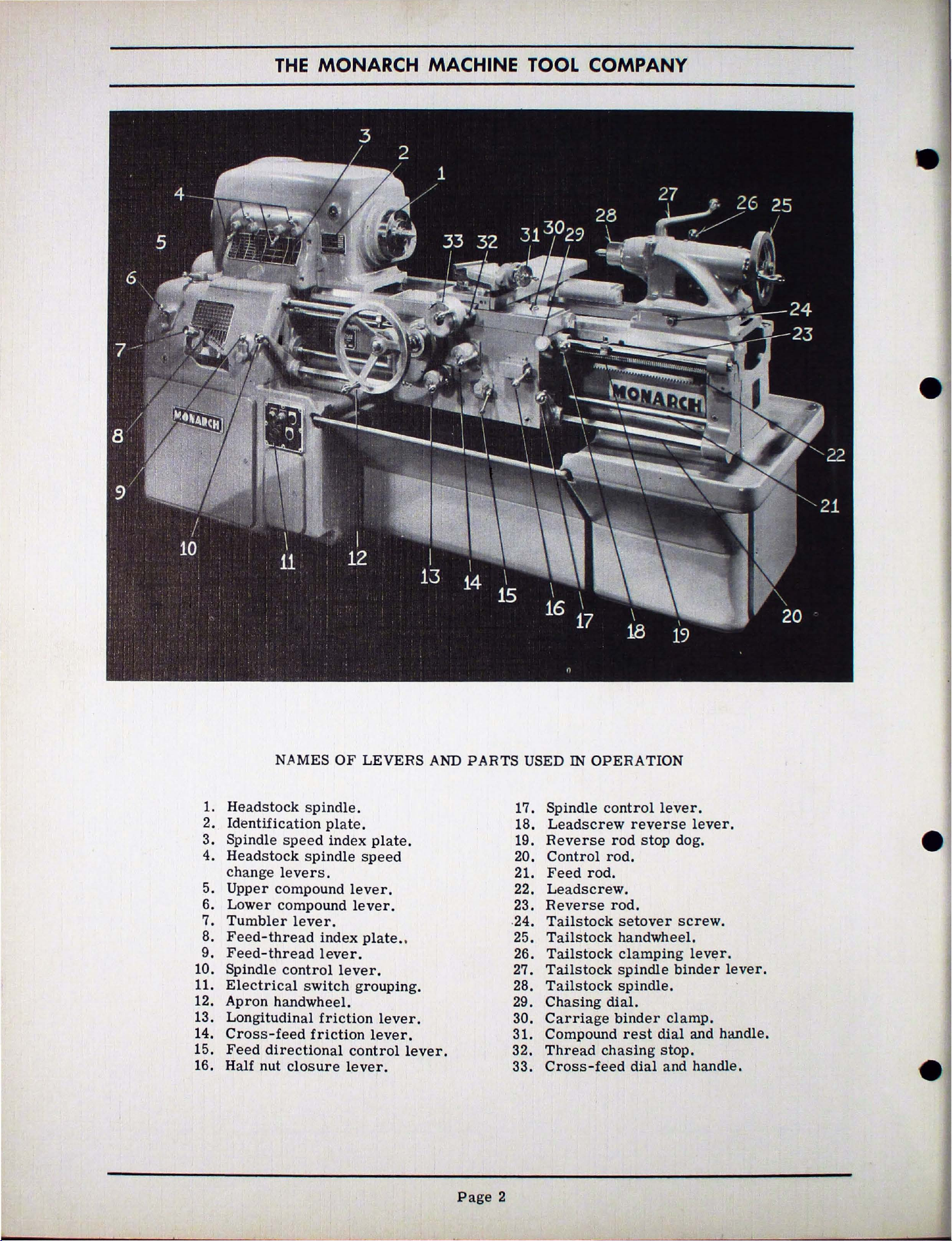
1.
Headstock
2.
Identification
3.
Spindle
4.
Headstock
change
5.
Upper
6.
Lower
7.
Tumbler
8.
Feed-thread
9.
Feed-thread
10.
Spindle
11.
Electrical
12.
Apron
13.
Longitudinal
14.
Cross-feed
15.
Feed
16.
Half
NAMES
spindle.
speed
spindle
levers.
compound
compound
lever
control
switch
handwheel.
friction
friction
directional
nut
closure
OF
plate.
index
lever.
.
index
lever.
lever.
control
lever.
LEVERS
plate.
speed
lever.
plate
.• 25.
grouping.
lever.
lever.
lever.
AND
PARTS
USED IN
17.
Spindle
18.
Leadscrew
19.
Reverse
20.
Control
21.
Feed
22.
Leads
23.
Reverse
-
24.
Tailstock
Tailstock
26.
Tailstock
27.
Tailstock
28.
Tailstock
29.
Chasing
30.
Carriage
31.
Compound
32.
Thread
33.
Cross-feed
OPERATION
control
rod
rod.
rod.
crew.
rod.
setover
handwheel.
clamping
spindle
spindle.
dial.
binder
chasing
reverse
stop
rest
dial
dial
lever.
clamp.
stop.
and
lever.
dog.
screw.
lev~r
binder
and
handle.
-
.
lever.
handle.
-
Page
2
Page 3
SERIES
60
OPERATOR'S
MANUAL
e
-
INTRODUCTION
Your
better
It
made Monarch the accepted
Held
higher
effort
ness.
Give
cision tool
instructions
will
over
After
the skids, remove the packing
box
and
discrepancy
ately
Sidney,
machine, mention
stamped
the
front
stock
the
flat.
until
of installation.
Monarch
work
has
inbuilt
for
many
speeds
so
necessary
your
deserves.
be
rewarded
the
years.
RECEIVING
the
check
to
The
Ohio.
on
of the
end of the
The
it
is
moved
lathe
with
less
operator
precision
years.
and
with
for
Series
contained
lathe
the
found should
Monarch
Always,
the
identification
headstock
bed
lathe
as
60 the
Follow the suggestions and
in
by
superlative
AND
has
shipment.
Machine
the
serial
between the
should
close
will
of the kind which
standard
It
is
the
maximum
this
CLEANING
been
be
when
and
remain
as
possible
produce
fatigue.
provided
ease
care
handbook and you
uncrated
list
Any
reported
Tool
referring
number.
plate
also
more
in
the lathe
with the
of
operating
productive-
which a
performance
from
shortage
attached
on
front
on
to the point
pre-
down
the
parts
immedi-
Company,
to
This
the
tail-
"V"
the
skids
and
has
the
and
to
or
is
to
From
of
the
the working
and
levers
cation of a
naptha removes
lathe
film
Be
and
moving
result
and control
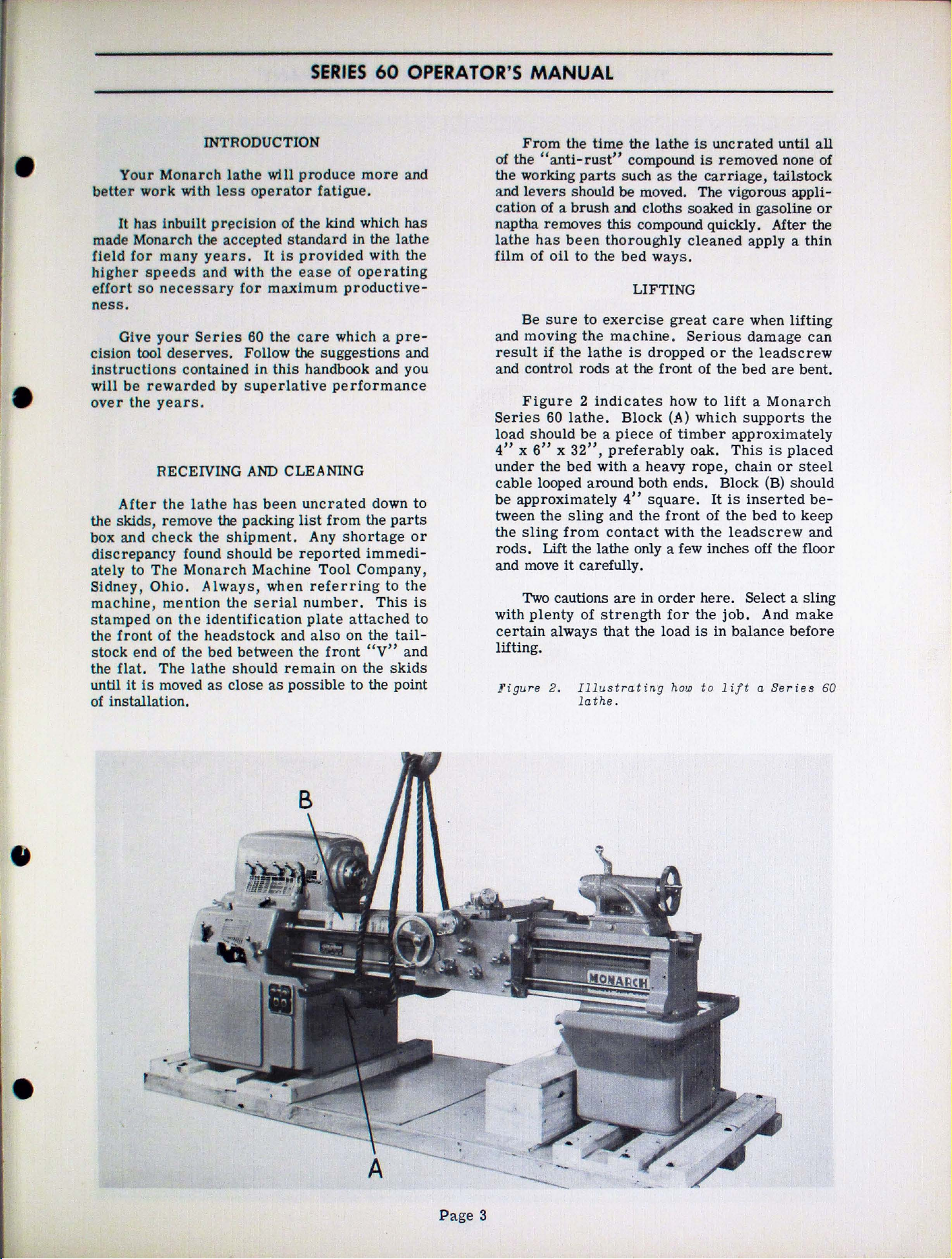
Figure 2 indicates
Series
load should
4" x 6" x 32",
under
cable
be
approximately
tween
the
sling
rods.
and move
Two
with
certain
lifting.
Figure
the
time
"anti-rust"
parts
should
brush
has
been
of
oil
to
the
sure
to
the
if
the
lathe
rods
60
lathe.
be a piece
the
bed
looped around both ends. Block
the
sling
from
Lift the lathe only a few inches off the floor
it
carefully.
cautions
plenty
of
always
2.
Illustrat
lathe.
the lathe
compound
such
as
be
moved. The vigorous appli-
am
cloths soaked
this
compound quickly. After the
thoroughly
bed
ways.
LIFTING
exercise
machine.
is
dropped
at
the front of the
Block
of
preferably
with
a heavy
4"
square.
and
the
contact
are
in
order
strength
that
the
ing
the
great
how
(A)
timber
front
with
for
load
how
is
uncrated
is
removed none of
carriage,
in
cleaned
care
Serious
or
the
to
lift a Monarch
which
approximately
oak.
This
rope,
the
is
chain
It
is
of
the
the
leadscrew
here. Select a sling
job.
in
balance
to
lift
until
tailstock
gasoline
apply a
when
damage
bed
supports
inserted
lifting
leadscrew
are
is
placed
or
(B)
should
bed
to
And
make
before
a
Series
bent.
steel
keep
all
or
thin
can
the
beand
60
-
-
t
..,,_
-..___
Page
3
Page 4
THE
MONARCH MACHINE TOOL COMPANY
In
order
face
accurately
free
from
foundation
ine
tool.
cret
e.
that
the
The next
cannot
w
ith
level
the
a
cross
bed
ible
Eight
are
plate
screws
machine
a
week
should
pending upon
be
the
and two
front
the
.
Inside
by opening the doors,
or
supplied
under
until
for
be
for
twist
is a "must"
Preferably,
If
this
floor
step
laid
utmost
parallels.
and
rear
parallels.
the
more
with the
each
the
should
the
checked
the
INSTALLATION
the
machine
the
bed
must
and
distortion.
for a precision
it
should
is
not
possible,
be
rigidly
is
leveling and too
on
the
care.
flats
cabinet
round,
leveling
lathe
be
checked
first
every
nature
two
supported.
importance
Use
Place
and
Do
this
legs,
are
countersunk
machine.
screw
is
level
months.
two
of
to
turn,
at
be
it
a good
the
lay
the
at
both
and
readily
the leveling
leveling
Place a leveling
and
at
both
for
level
months
the
foundatio~
bore
all
times
A
good
of heavy
is
essential
much
of
doing
machinist's
parallels
level
ends
adjust
ends.
about
After
or
and
be
solid
mach-
con-
stress
this
on
square
of the
access-
screws.
plates
the
The
once
that
so
de-
..
it
LUBRICATION
More
lubrication
operation
covered
next
To
which
and
to
familiarize
of
the
mechanism
follows
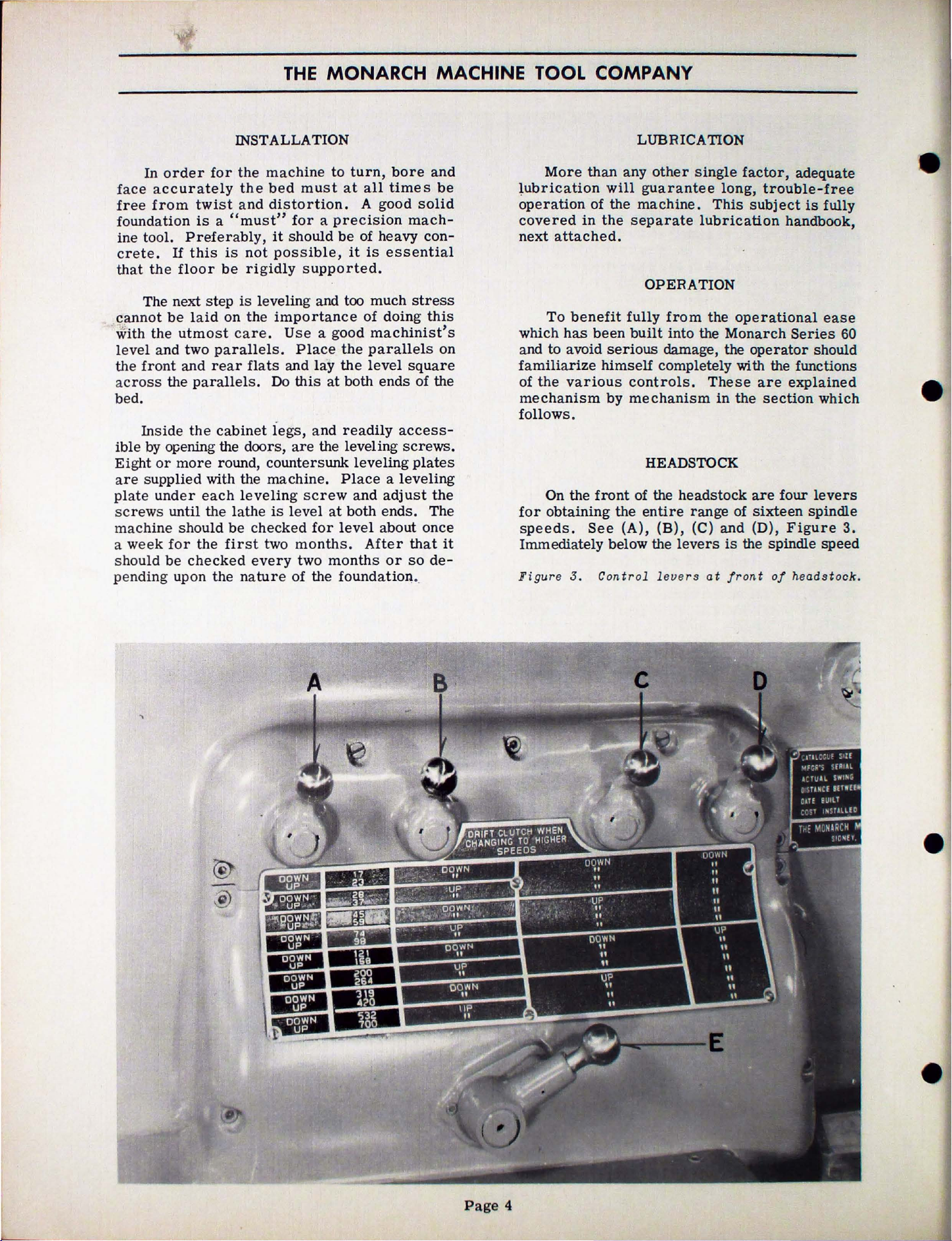
On the
for
obtaining
speeds.
Immediately below the
Fi
gur
than
any
will
guarantee
of
the
machine.
in
the
separate
attached.
OPERATION
benefit
has
avoid
various
.
e J . Cont rol l
been
serious
himself
by
front
the
See
fully
built
controls.
mechanism
HEADSTOCK
of the
entire
(A),
other
damage, the
completely with the functions
(B),
eve
single
Th
lubrication
from
into
the
the
These
headstock
range
(C)
levers
rs at fro
factor,
long,
in
and (D),
trouble-free
is
subject
operational
Monarch
operator
are
the
section
are
of
sixteen
is
the spindle
nt
adequate
is
fully
handbook,
ease
Series
should
explained
which
four
levers
spindle
F i
gure
speed
of
headstock
-
60
-
3.
.
...
~
-
@
[,ljl\N
II
ti
"
"
II
"
-
"
Page 4
-
Page 5
SERIES
60
OPERA
TOR'S
MANUAL
-
-
-
-
••••••••••••
-
••
•11111111111111
-
••
•1111111111111111111111
'11111111111111111111
111•111111111111111
11
11•11
111111111111111111
•
11
.
-1
,
,_
w
-
-
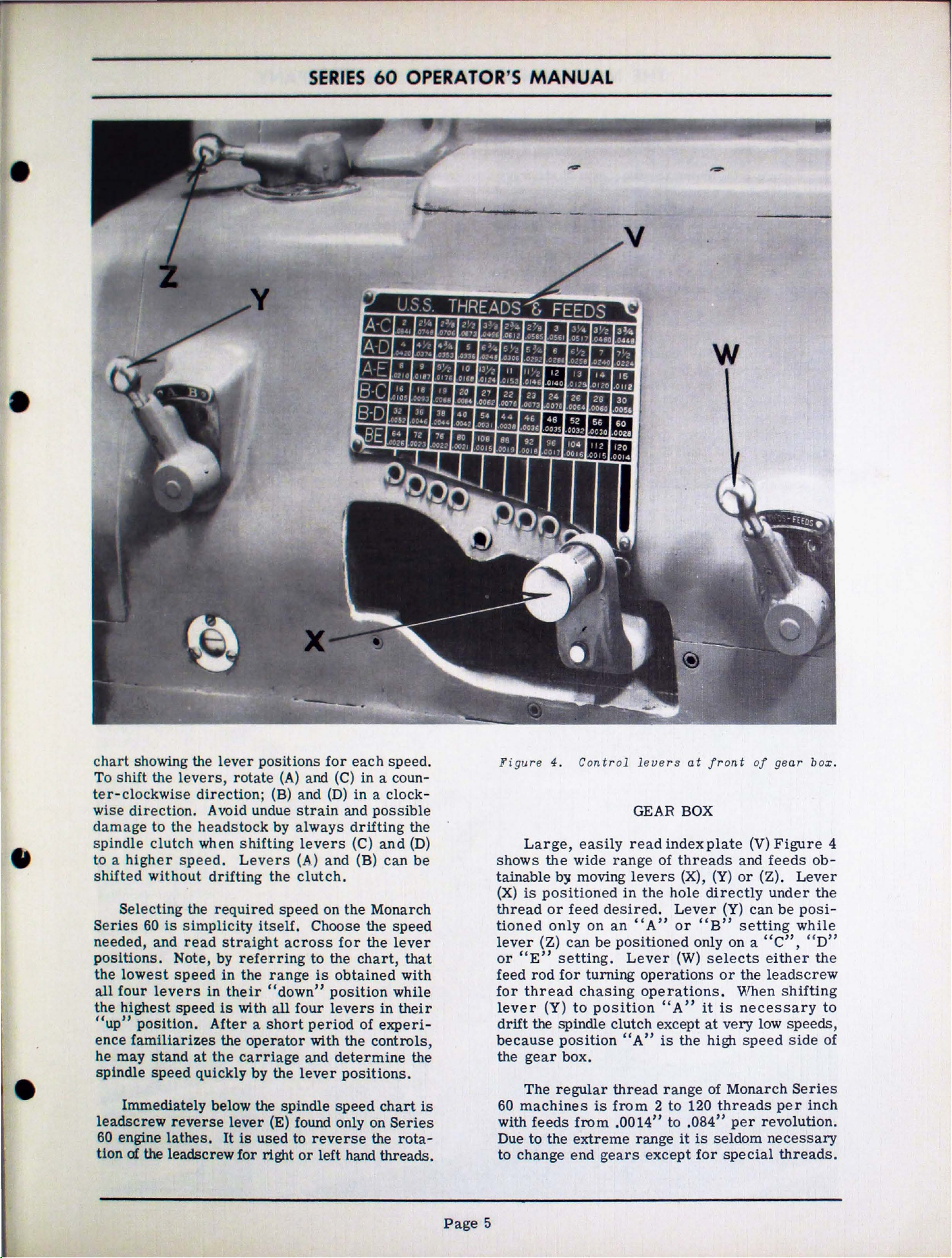
chart
To
ter-clockwise
wise
damage
spindle
to a
shifted
Series
needed,
positions.
the
the
showing the
shift
the
direction.
to
clutch
higher
without
Selecting
60
lowest
all
four
highest
"up"
ence
he
spindle
leadscr
60 engine
tion
position.
familiarizes
may
stand
speed
Immediately
ew
of
the leadscrew
the
is
and
Note, by
speed
levers
speed
reverse
lathes.
lever
levers,
direction;
A void undue
headstock
when
speed.
drifting
the
required
simplicity
read
in
After a
at
the
quickly
below the spindle
positions
rotate
shifting
Levers
itself.
straight
referring
in
the
their
is
with
the
operator
carriage
by
lever
It
is
used
for
for
each
(A)
and (C)
(B) and
strain
by
always
levers
(A)
the
clutch.
speed
Choose the
across
to
range
"down"
all
short
the
(E) found only on
right
is
four
period
with
and
lever
to
reverse
or
left
in
(D)
in a clock-
and
drifting
(C)
and
(B)
on
the
for
the
chart,
obtained
position
levers
of
the
determine
positions.
speed
hand
speed.
a coun-
possible
the
and
(D)
can
be
Monarch
speed
the
lever
that
with
while
in
their
experi-
controls
the
chart
Series
the
rota-
threads.
is
Figure
shows
tainable
(X)
thread
tioned
lever (Z)
or
feed
for
lever
drift
,
because
the
60
with
Due
to
4. Cont r ol
Large,
the
by
is
positioned
or
feed
only
can
"E"
setting.
rod
for
thread
(Y)
the spindle
position
gear
box.
The
regular
machines
feeds
to
the
change
end
easily
wide
to
from
extreme
range
moving
desired.
on
an
be
positioned
turning
chasing
position
clutch
thread
is
from 2 to
.0014"
gears
levers
GEAR
read
index
of
levers
in
the
hole
"A"
Lever
operations
operations
"A"
except
"A"
is
range
to
range
except
at
front
BOX
plate
threads
(X),
(Y)
directly
Lever
or
"B"
only
(W)
selects
it
at
the
high
of
120
.084"
it
is
for
of
(V)
and
or
(Y)
can
setting
on a "C",
or
the
. When
is
necessary
very
speed
Monarch
threads
per
seldom
special
gear
bo
x.
Figure
feeds
(Z).
under
either
leadscrew
low
revolution.
necessary
ob-
Lever
the
be
posi-
while
" D"
the
shifting
to
speeds,
side
Series
per
inch
threads.
of
4
Page
5
Page 6

THE
MONARCH MACHINE TOOL COMPANY
Figure 5 indicates
ous
controls
movements
handwheel,
parallel
(B),
moves
to the bed. Compound
the
tool manually at any
Spindle
means
be
ine
trol
lever
carriage
toward
slide
downward,
the
the
and (F)
of
way down,
tral
tion
the
down
headstock
of
performed
where a similar
rod.
which,
the
power
preselected
operator.
it
pressure.
Feed
position.
the
carriage
cross
position,
provided
to
the
moves
to
the
bed.
the
tool
rotation
lever
(E)
to
is
they
directional
slide
and
(D)
at
the
is
the
when
move
headstock -or
feed
causes
unnecessary
at
control
feed
NOTE--When
If
they
are
In
the
feeds
feeds
the
the
cross
pushed
APRON
the
functions
to
impart
cutting
the
cutting
Cross
manually
rest
handwheel (
angle
is
started
which
headstock
lever
carriage
the
the
either
do
in
lever,
carriage
operations
is
downward,
preselected
the
lever
cross
toward
to
apply a
not
need
(G),
up
or
toward
in.
When
slide
the
tool.
(A),
tool
slide
at a right
to
the
and
end
attached
power
tailstock.
(E) when
slide
using
engage
of
adjustment.
is
shown
straight
the
in
feeds
feeds
of the
necessary
the
apron
manually
handwheel,
C)
moves
bed.
stopped
may
of
the
mach-
to
the
feed
control
causes
feed
either
Cross
pushed
to
move
or
away
levers
great
tailstock
about
out
the
straight
toward
out.
amount
in
posi-
vari-
angle
by
also
con-
the
at
from
(E)
half-
neu-
and
the
If
threads
engaged
control
gaged
full
neutral
lever
gaged
safety
lathe
to
engage
gaged.
uations
to
engage
operations.
being
may
to
the
as
18,
the
half
four
the
half
graduations--No.
The
the
half
each
(K)
the
carriage
the
cross
Figure 5.
to
the
lever,
position
engagement.
position
(H). When
lever
feature
should
Thread
90°
chased
be
dial.
22,
graduations.
chasing
time.
is
(E)
the
lever
chasing
apart,
the
On
engaged
For
23
and
nut
may
nut
may
of
nut
be
the
carriage
to
slide.
Front
compound
are
to
be
leadscrew
(H).
It
is
and
should
Always
before
lever
cannot
intended
operator
(E)
while
dial
is
used
half
nut
any
even
is
divisable
at
any
any
full
so
on
be
engaged
When
be
engaged
1 and No. 3
quarter
engaged
the
bed
close-up
rest.
chased,
by
means
illustrated
be
straight
have
attempting
(H)
is
partly
be
engaged.
to
prevent
inadvertently
lever
0),
which
for
determining
during
thread
by
point
at
locking
ways
without
number
(1'.1,0t
divisable
at
chasing
at
or
threads
the
same
stud,
when
of
apron,
the
carriage
of
half
in
its
disen-
down
lever
(H)
thread
where
four
of
any
any two
No. 2 and No. 4.
(G)
to
or
fully
This
damage
attempt
is
also
has
four
chasing
the
the
half
reference
threads
by
one
half
threads,
opposite
requires
graduation
used
cutting
carriage
in
engage
is
to
grad-
when
lead
such
four)
of
that
to
lock
with
is
nut
for
its
en-
the
en-
nut
the
and
-
a
-
-
-·-·-~
ii
•
•
Page
6
Page 7

SERIES
60
OPERA
TOR'S
MANUAL
-
-
figure
6,
Automatic
side
length stop at
of
apron.
left
hand
There
est
slide
The
cross
machine.
that
diameter
le
dial
Thread
the slow and tedio us oper
the
cross
:
chasing
dial
only
proceed with the next cu
ing
way
cross
stop
dial
are
two
sets
of
the
operator
is
feeding
second
slide
The
is,
.
001"
or
The
cross
ver
(B)
whenever
for
repositioning
chasing
tool
to
zero
feed dial,
stop,
when repositioning the to ol.
to
run
stop
is
engaged (by tu
in),
there
feed
positions
always
is
for
toward
set
of
numbers
is
feeding
dial
is
graduated
on
the
dial
the
bore
of
feed
dial
it
is
stop
or
some
after each cut. With the
the
operator
the
cross
are
three
handwheel
at
which two
reads
the
same.
numbers.
reading
the
front
towa
equals
the
is
locked
necessary
in
relation
(C)
is
ation
other readi
need
slide
t.
When the thr
rni
complete turns
between
The
when
of
is
use
rd
the rear
to
work
.
used
of repositioning
not
It
in
to
ng the knob
the
points
set
near-
the
cross
the
machine.
d when
read direct,
. 00
1"
by
means
to move the
to
the
to
eliminate
ng
look
is
necessary
the
ead
in
the
diameter
of
on
on
thread
at
stop
all
of the
and
the
the
the
tool.
and
chas
of
the
the
-
the
out
-
-
APRON CONTROLLED LEADSCREW REVERSE
Leadscrew
found
Lathes.
(E)
all
screw
convenient
for
where the half nut should not
chasing of
the
to a shoulder
and
apron.
chasing
operations.
end
vides an
ing
tion the threading
point
verse
against
Collar
is
CR~
only
on
Its
Figure
Series
example,
automatic
Figure 6 shows
adjusting
of
toward
locked
Cross
graduated to
60
reverse
short
This
threads
the
leadscrew
automatic
on
the
lever
adjusting
(B)
is
in
FEED
feed
reverse
Monarch
functions
3 on
the
Engine
from
during
chasing
threads
length
or
in a blind
collar
stop
but
A
similar
the
tails
or
work;
in
neutral
collar
for
the
place
DIAL
diameter
read
lever
Series
are
front
Lathes.
the
thread
threads
and,
stop,
the
automatic
at
the
is
a tim.e
also
stop
reverse
stop
with the
tock.
then
with
AND
in
To
turning tool
with
position,
(B)
final
nut
THREAD
one thousandths of
60
the
of
the
Control
apron
chasing
be
in
connection with
chasing
hole.
left
hand
saver
for
ordinary
on
control
set
the
and
tighten
close
(D).
dial
(A),
(I)
Figure 5 is
Toolmaker's
same
is
with
engaged;
the
carriage
stop
to
leadscrew
place
adjustment
CHASING
as
lever
headstock
of
lead
particularly
operations
odd
leads
speed
threads
length
side
of the
not
only when
turning
right
rod
mov-
(A),
posi-
the
required
stop
stud
Figure
an
of
--
up
stop
hand
pro
-
re-
(A)
(C).
and
STOP
7,
is
inch.
-
Figure
are
pose
form
straight
feed
are
ing
in
to
allows
disengaging
(D)
7. Cl ose- up
di
al.
Graduations
used
in
conjunction with lock (B)
of
imparting
during
in
with
taken on
is
the
the
the
equals
the
feed
in
the
both
procedure.
stop.
cross
stop
.001".
of
cross
(D)
close
extra
finishing
of
the
result
sides of the thread. The follow-
Then,
slide
(C).
accuracy
tool
that
Run
unlock
to
E~ch
f eed micromete
to the
cut.
instead
the
the
lever
be
moved
of
the
front
This
finishing
cross
of the
for
the
pur-
to
the
thread
permits
of
an
angle
cuts
feed
dial
{B)
which
in
without
graduations
dial
r
Page
7
Page 8

THE
MONARCH MACHINE TOOL COMPANY
-
~.)
J
-
The
wo
rk
supporting
p
erform
ing,
reaming
Ta
ilstock
to
traverse
permit
is
gr a
duated
tate
s the
the
taper
crank
the
locks
be
clamping
stock
the
center
Pulling
the spindle
done
to
Figur
tailstock
other
accurate
before
the
important
and tapping.
handwheel
or
in
removal
center
spindle
is
automatically
lever
lever
bed
--
e 8.
feed
inches.
hole.
in
the
which
for
Quick
TAILSTOCK
on
any
device
functions
spindle
drilling
of
drills
To
back
(D)
into
in a clockwise
position.
start
quickly
such
.-
acting
lathe
but
(A),
to
Tang
of
operations
is
it
may
such
Figure
(B)
in
depth
slot
and
reamers
remove
the
tailstock
ejected.
This
should always
the
cut.
clamps
type
tailstock
primarily
be
used
as
drill-
8,
is
used
or
out.
spindle
(C)
facili-
from
the
center,
until
direction
(E)
is
the
tail-
as
drilling
a
to
To
(B)
a
suppli
ed on
am
reaming.
Series
60
Engine
On
is
supplemented by clamping nut (F) which should
be
tightened
or
in
amount
and
20"
ing
nut
gine
Lathe
quick clamping
of clamping nuts.
Aligning stud (
to
true
not
equipped with a
is
sometimes
center
studs,
Series
60
Toolmaker's
Lathes.
14"
and
when
any
case
of
pressure
machines
on
top
tailstocks,
center
for
taper
the
other
60 Toolmaker' s
It
is a feature
Lathes
16"
machines
turning
when
against
there
of
the
lever
G)
is
with the
taper
utilized
turning.
being
work
there
the
is
tailstock.
while
(E), have double the
used
headstock.
turning
to
move
There
at
the
Lathes.
found on
clamping
is a considerable
tailstock.
an
additional
not
to
bring
rear
all
but
not on
between
Series
provided
the
On
attachment
the
tailstock
are
two of
of
the
Monarch
Series
lever
cent
On
clamp-
60
number
tailstock
machines
tailstock.
(E)
ers
18"
Enwith
,
it
off
these
•
•
Page
8
Page 9

THE
MONARCH MACHINE TOOL COMPANY
-
"--
.,
..
_
..,
11
'-.&..>-
-
The tailstock
wo
rk
supporting
pe
rform
in
g,
to
traverse
permit
is gr a
tat
es
the
crank
the center
locks
be
done
clamping
stock
other
reaming
Tailstock
accurate
duated
the
taper
the
Pulling
the
before
to
the
Figure 8, Quick
TAILSTOCK
on
de
vice
important
and tapping.
handwheel
or
feed
spindle
drilling
in
inches.
r e
moval
cent
spindle
is
lever
spindle
lever
bed
of
drills
er
hole.
back
automatically
(D)
in
position.
the
start
which
for
such
--
acting
any
lathe
but
functions
(A),
to
Tang
To
into
in a clockwise
of
quickly
operations
is
it
may
Figure
(B)
in
depth
slot
and
reamers
remove
the
tailstock
ejected.
This
the
cut.
clamps
primarily
such
should
t ype tailsto
be
used
as
8,
or
out.
spindle
(C)
the
center,
direction
(E)
the
as
drilling
drill-
is
used
To
(B)
facili-
from
until
always
is
tail-
to
ck suppli
a
a
ed on Ser i
am
reaming.
Series
60
is
be
or
amount
and
ing
gine
quick
of
to
not
is
center
studs,
60
Engine
On
14"
supplemented
tightened
in
any
of
20"
machines
nut
on
Lathe
clamping
clamping
Aligning
true
center
equipped
sometimes
for
the
es
60
Toolmaker's
It
is a feature
Toolmaker's
Lathes.
and
16"
by
when
turning
case
pressure
taper
other
when
top
of
the
tailstocks, while
lever
nuts.
stud ( G)
with
with a
utilized
turning.
being
Lathes
machines
clamping
there
against
there
tailstock. Series
(E), have double
is
used
the
headstock.
taper
to
at
the
Lathes.
found on
but
not
clamping
nut
(F) which should
work
is
turning
move
There
between
is a considerable
the
tailstock.
an
additional
not
provided
to
bring
rear
the
On
attachment,
the
tailstock off
are
two
of
the
all
Monarch
on
Series
lever
centers
On
clamp-
60
the
number
tailstock
machines
of
these
tailstock.
(E)
18"
Enwith
it
-
-
Page
8
Page 10

SERIES
60
OPERA
TOR'S
MANUAL
-
-
Following
Monarch
1.
Position
is
2.
Push
toward the headstock, position bed
(B) as
(C)
3.
Set
ing
at
(G).
4.
Lock nut (H)
swivel and a
of
stud
TAPER ATTACHMENT
are
the
steps
anti-friction
the
about
the
the
l"
slide
illustrated,
and
hex
swivel (E)
stud
(F) and
hairline
swivel
(I)
and loosen
taper
carriage
from
(A),
Figure
nuts
(D).
at
required
reading
through
at
the
similar
at
the
the
tighten
right
nut on the underside
left
stud
in
the
setting
attachment.
so
the
turning
end
of
the
9,all
the
knurled
taper
the
graduations
magnifying
hand end
hand end,
0).
tool
'M'.>rk,
way
clamp
nuts
by
turn-
lens
of
tighten
of
in
the
the
5, Now, turn the
depth
pound
To disconnect
turning,
nuts
ing
bed
have
of
the
bed.
to
turn
threads.
maxim
(D)
of
stud
with
to
carriage
The
um
loosen
and
(K),
the
be
taken
Monarch
tapers,
Maximum
length
in
the
usual
slide
.
ire
stud
tighten
bracket
carriage.
off
would
taper
bore
at
taper
manner
taper
(I),
tighten
stud
(K).
(B)
Therefore
unless
run
attachment
tapers
taper
one
by feeding the tool to
with the
attachment
stud
After
will
slide
extreme
it
off
the
or
chase
per
foot
setting
is
com-
for
straight
0),
loosen
the
tighten-
along
it
does
movement
end
of
can
be
used
tapered
is
4"
18".
the
not
the
and
-
Tigure
9. Top
view
of
anti-friction
bearing
taper
attachment
.
-
Page
9
Page 11

THE
MONARCH MACHINE TOOL COMPANY
The
spindle
lµlown
method
Two
illustration.
locks
position
the
in
tightening.
that
gradually,
other
the
plates
before
11,
lock
Figure 10.
as
There
of
(A)
spindle
which
the
until
It
is
face
and
mounting
helps
spindle
of
them,
camlocks
equally
of the
CAMLOCK
on
Monarch
the
Camlock
attaching
are
six
(A)
The
indicates
because
face.
the
camlocks
When
rotating
all
the
spindle
fixtures
give a clearer
nose
Series
spindle
chucks,
camlocks
Figure
small
that
these
Arrows
this
be
the
locks
important
be
takes
construction.
60
nose
SPINDLE
Series
spindle
plates
in
10,
clearly
indicating
they
are
lines
(B)
should
is
done,
tightened
spindle
are
tight.
that
and the
free
place.
American
back
from
conception
.
60
because
and
the
spindle
show
line
in
the
are
parallel
show
the
be
rotated
it
is
evenly.
from
the
cam
of
dirt
Drawing,
of
standard
lathes
of
fixtures.
nose.
in
on
cam-
unlocked
with
direction
important
Do
this
one
to
studs,
all
chucks,
and
burrs
Figure
the
Cam-
Camlook
is
the
the
for
the
Figure
The
located
directly
reach
trol
buttons
tion.
11.
Drawing showing
look spindle
ELECTRICAL CONTROL
electrical
on
the
below
of
the
operator
clearly
front
the
control
of
gear
at
marked
nose.
the
box.
all
panel,
left
for
construction
times
PANEL
Figure
hand
U-
is
quick
cabinet
within
with
the
identif-ica-
of
12,
-
-
Cam-
is
leg,
easy
con-
Stop
forward
the
other
stop
the
sary.
tion
of
Figure
switch
from
buttons
machine
This
is a safety
both
the
12.
(A)
is
the
panel
so
quickly
operator
Electrical
hand
cabinet
red
in
somewhat
as
to
should
feature
and
control
le9.
color
make
the
and
farther
it
possible
this
be
for
the
machine.
panel
protrudes
than
to
neces
protec-
on
left
·-
-
Page
-
10
Page 12

-
-
CARE
The
proper
Monarch
ing
the
have
machine.
A
and condition of
The
which
wtth a clean,
will keep the finish looking
long while.
factory
sionally
may have to
Js
described
lathe
accuracy
been
Monarch
All
carefully
good
machinist
is
easy
adjustments
before
, however,
AND
care
ls
very
and
the
Series
to
keep
dry
cloth
shipment
be
made. The
in
the
following
ADJUSTMENT
and
important
ease
designed
is
judged
tools
60
clean.
or
kerosene
are
of the machine.
certain
SERIES
adjustment
for
of
operation
and
built
by
the appearance
with which
has
very
Occasional
soaked
bright
expertly
further
manner
pages.
and new
made
adjustments
of
60
of
your
maintain-
which
into
he
works.
fine
finish
wiping
cloth
for
at
Occa-
doing
OPERATOR'S
a
positive
tion
pin
clockwise
next
the
a
the
this
sufficient
t.o
the
the
ine s
of
pressure.
much
the
clockwise direction.
MANUAL
drive
required.
(B)
all
locking
next
clutch control
naps
In
the
pressure
procedure
HEADSTOCK
II
the
way
direction
hole.
amount
hole,
into
position
event
by
for
a long
the clutch needs adjusting,
out
until
In
of
adjustment, turn
repeating
lever
the
is
required
turning
SPINDLE BEARINGS
period
and
pin
case
at
the
with a
clutch
spider
with no
turn
spider
(B)
drops
this
does
the ope
front
is
to engage
of the
moderate
too
tight
(C)
in a counter-
not give a
the
ration
it,
atten-
pull
(C)
in
a
into the
spider
until
mach-
amount
or
too
repeat
-
-
HEADSTOCK
Tigure
sible
hand end of the
lifted
tion
1$. Cover removed
olutoh.
The
spindle
by
the
removal
off
after
The clutch
discs,
which when
SPINDLE DRIVE CLUTCH
-A
'
drive
headstock.
ta.king
consists
clutch
of
out
properly
. , .:
to
show
is
the
cover
This
stud
(A),
of a multiple
adjusted
-8
spindle
readily
at
cover
Figure
set
drive
acces-
the
left
may
13.
of
fric-
deliver
be
Figure
or
being
To do
position, that
Then,
and
ings
in
nut
there
dle. Carefully avoid
give too much
cured
with
as
care
14. Cover removed
spi
ndle.
After
so,
if
This
nuts
well
your
lathe
depending
performed,
this,
shift
all
is,
on a line
turn
the spindle by hand
the
re
is
very
need
(B)
adjusting.
is
done
by
(A)
and
(B),
and
tightening
is
a noticeable amount of
drag.
by
locking
its
set
screw
as
locking
to
avoid getting the }?earings too tight.
to
show
has
been
upon
the
check
headstock
parallel
little
loosening
Figure
adjusting
over-adjustment
The new
adjusting
and
its
set
run
nature
the
spindle
levers
at
or
no drag>
14;
drag
adjustment
nut
tightening
screw.
left
end
of
for
200
hours
of
the
work
for
drag.
to
neutral
with the spindle.
the spindle
the
set
loosening
nut
on the
which will
(A)
in
lock
Do
nose
the
bear-
screws
lock
(A)
until
spin-
is
position
nut
this
with
se-
(B)
Page
11
Page 13

THE
MONARCH MACHINE TOOL COMPANY
Figure
the
cover
cation
Figure
a
ssembly
brake,
of
adjusting
tighten
adjust
The
start
is
with
and
all
the way up.
the
l'igu
re 15 - bel o
HEADSTOCK
15
is
a top
removed
of
the
spindle
16
is a close-up
out
of
the
lift
locking
gear
(A),
and
counter-clockwise
the
brake
spindle
stop
lever
too
brake
lever
No
in
the up_
w.
SPINDLE
view
of the
and
with
(A)
brake.
of the
machine.
spring
tightly.
at
upward
Top
cover
(B)
to
turn
gear
is
engaged when the
the
front
pressure
position.
view
of
removed.
BRAKE
headstock
showing
spindle
To
clear
(A)
clockwise
to
loosen.
of
the
headstock
the
adjust
the
Do
spindle
machine
is
required
with
lo-
brake
the
teeth
to
not
with
ligure
A
>,
.
16 -above.· Close-up
assembly.
of
spindle
-
-
brake
Page
•
•
12
Page 14

SERIES
60
OPERATOR'S
MANUAL
-
-
APRON AND SLIDES
The
justable
This
base
at
the
rear
ure
18.
To
nuts on
nuts.
tension.
much
and
the
(B)
two
Figur
Reverse
tension
e 1
main
base
is
by
tighten
each
adjusting
Always
may
covers
8.
VEE BELTS
drive
hinged
on
be
Cover removed
mot or mount
motor
inside
adjusting
vee
the
at
the
at
belt
bolt
operation
be
careful not
the
belts.
reached
the
back
left
the
bolts
tension,
ing.
is
mounted on
hand
front
and
to
Adjusting
easily
of the cab
to
cabinet
and
(A)
and (B),
loosen
tighten
loosen
to
by
show main drive
an
ad-
leg.
supported
Fig
the
top
the
lower
the
belt
place
bolts (A)
removing
inet
too
base.
-
-
T i
gur
e
17. Apr
The longitudina
justed
in
halfway down
tral
clutch
(B
cross
is a si
slide.
slight
are
gibs, they
throwing the gibs out of
by
or
out
position
is s i
).
Screws
feed
milar
drag
drawn
turning
so
milarly
(C)
slide
The
to the
too
may
the l
toward
shown.
screw
gibs
on
l fe
screw
ever
is
the
adjusted
and
(D)
and compound
adjustment
should
slides.
tightly
create a bad
and
sli
de
adjustmen
ed
friction
(A),
Figure
moderately
apron
The
cross
are
for
be
If the adjusting
against
line
from
by
means
adjustment
slide
at
the
adjusted
each
bearing
.
clutch
17,
tight
the
feed
of
gibs.
rear
to
end
surface
t s.
is ad-
either
about
neu
friction
screw
of the
There
of each
give
screws
of
the
by
- .
a
-
Page
13
Page 15

THE
MONARCH MACHINE TOOL COMPANY
One of
the
THE
most
MONARCH
modern
and
PLANT
best
equipped
AT
SIDNEY,
machine
tool
OHIO
plants
in
America
-
e ,
Page
•
-i
14
 Loading...