

Page 1
© Monarch Instrument 2002 all rights reserved
1071-8011-310
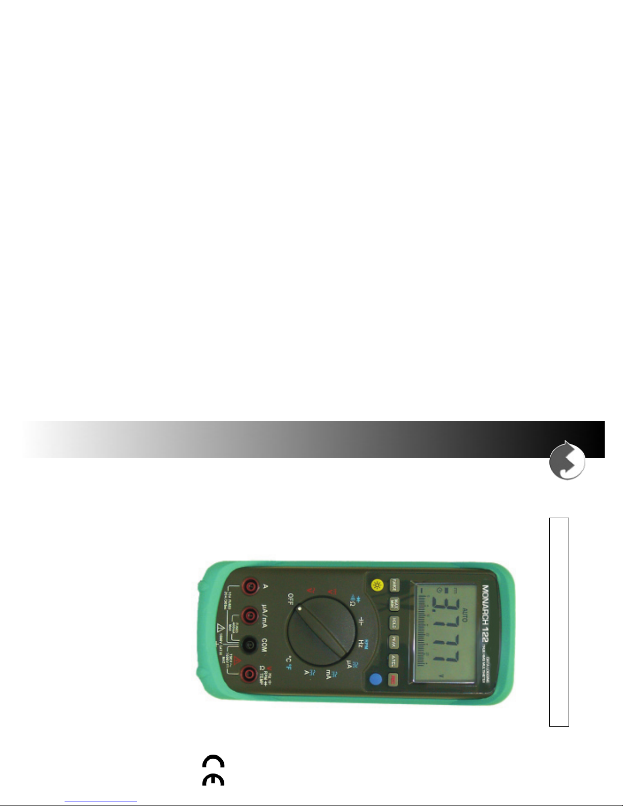
True RMS Datalogging Multimeter
Monarch 122
15 Columbia Drive
Amherst, NH 03031-2334 USA
Phone: (603) 883-3390
Fax: (603) 886-3300
E-mail: support@monarchinstrument.com
Website: www.monarchinstrument.com
MONARCH INSTRUMENT
Instruction Manual
Page 2

14. With the exception of replacing the battery or fuses, this
13. To avoid false readings, replace the battery immediately
12. Keep fingers behind the finger guards on the test leads
11. Exercise extreme caution when working with voltages
10. Do not connect the test leads to a voltage source when
9. Discharge all capacitors in a circuit before measuring
8. Do not measure resistance or continuity in a circuit or test
7. Do not exceed the rated voltage between any input jack
6. Do not, under any circumstances, exceed the maximum
5. Ensure the Function Selector switch is in the proper
4. Ensure the test leads are installed in the proper connectors
3. Ensure that the instrument and test leads are in good
2. Do not use this instrument in any manner inconsistent with
1. Read and follow all instructions in this manual carefully,
instrument is not user serviceable. For technical
assistance, contact the sales organization from which you
purchased the product or Monarch Instrument directly.
when the low battery indication appears.
when making measurements.
above 60Vdc or 30Vac. Such voltages pose a shock hazard.
the test leads are connected to the µA /mA or 10A input jacks.
capacitance.
diodes while power is applied to that circuit.
and ground.
ratings of this instrument.
position for the measurement to be made.
for the measurement to be made.
condition with no visible signs of damage before use.
these operating instructions or under any conditions that
exceed the environmental specifications stated.
and retain this manual for future reference.
Safeguards and Precautions
referencing this clause.
SELLER warrants that any software supplied will operate in accordance with the
documentation or manual supplied therewith in all material respects when used in strict
compliance with such documentation or manual. Notwithstanding the foregoing, BUYER
acknowledges that, since software is complex and therefore may have defects, BUYER’s
sole and exclusive remedy for any such defects or breach of this warranty shall be to
require SELLER, within a reasonable period of time, to provide all reasonable programming
services to correct programming errors in the software. Except as provided above SELLER
MAKES AND BUYER RECEIVES FROM SELLER NO EXPRESS OR IMPLIED WARRANTIES
OF ANY KIND WITH RESPECT TO ALL OR ANY PORTION OF SOFTWARE AND BUYER
HEREBY AGREES AND ACKNOWLEDGES THAT IT ACCEPTS THE SOFTWARE IN ‘AS IS’
CONDITION. SELLER HEREBY EXPRESSLY EXCLUDES ANY IMPLIED WARRANTIES
OF MERCHANTABILITY OR FITNESS FOR A PARTICULAR PURPOSE WITH RESPECT TO
THE SOFTWARE. BUYER agrees that any specific right or remedy granted to BUYER
hereunder with respect to any breach or default by SELLER shall be in lieu of all other
rights and remedies otherwise available to BUYER at law or in equity as the result of such
breach or default, regardless of whether based on contract, tort, strict liability, or other
theory of liability.
IN NO EVENT SHALL SELLER BE LIABLE FOR ANY SPECIAL, INDIRECT, INCIDENTAL,
CONSEQUENTIAL, OR PUNITIVE LOSSES OR DAMAGES (INCLUDING, BUT NOT
LIMITED TO, LOSSES OR DAMAGES FOR ANY LOST PROFITS OR LOST DATA) AS THE
RESULT OF ANY BREACH OR DEFAULT BY SELLER WITH RESPECT TO THE HARDWARE
OR SOFTWARE, EVEN IF SELLER HAS BEEN ADVISED OR MADE AWARE OF THE
POSSIBILITY OF ANY SUCH LOSSES OR DAMAGES AND REGARDLESS OF WHETHER
THE CLAIM IS BASED ON CONTRACT, TORT, STRICT LIABILITY, OR OTHER THEORY OF
LIABILITY.
This limited warranty does not extend or apply to consumables (including, but not limited
to, lamps and batteries, if applicable) or equipment, instruments or accessories which are
warranted separately by the original manufacturer of these items.
SELLER warrants hardware products to be free from any defect in materials or workmanship
for a period of one (1) year from date of shipment to BUYER. SELLER’s entire liability and
BUYER’s sole and exclusive remedy resulting from any defect in workmanship or material
in the hardware product covered by this limited warranty shall be limited to and fully
discharged by the SELLER’s option of replacement or repair of such item without charge.
The limited warranty provided in this clause is in lieu of all other warranties, expressed or
implied, arising by law or otherwise. ALL IMPLIED WARRANTIES OF MERCHANTABILITY
AND FITNESS FOR A PARTICULAR PURPOSE ARE EXCLUDED. This limited warranty
shall not be modified except by an arrangement signed by both parties specifically
LIMITED WARRANTY
Page 3
19
Importer (Amherst, NH) Alan Woolfson, VP Engineering (Authorized Signature)
th
July 2000
and therefore conforms in accordance with 89/336/EEC-EMC Directive. The
testing of this product was performed by GesTek EMC Lab. in July of 2000.
(Ref. No. 0007018E).
EMC: EN55022/1998, CISPR 22, Class B
to which this declaration relates is in conformity with the following standards:
Name: True RMS Multimeter
Model: Monarch 122
DECLARATION OF CONFORMITY
EN50082-1/1997 / EN61000-4 Series
Division of Monarch International Inc.
declares that the product:
15 Columbia Drive, Amherst NH 03031 USA
Monarch Instrument
7.0 Setup TestLink (Multimeter) – RS232 Interface Software
8.0 Running TestLink
6.3 Fuse Replacement .......................................................................................................
8.1 Open TestLink ...........................................................................................................
8.2 Real Time Tabular and Real Time Graph ................................................................
8.3 Datalogger .................................................................................................................
..................................................................................................
6.4 Closing the Instrument Case ......................................................................................
6.0 Battery and Fuse Replacement
5.9 Capacitance Measurements........................................................................................
6.1 Opening the Instrument Case .....................................................................................
6.2 Battery Replacement ...................................................................................................
...................................................................
5.6 Diode Tests...................................................................................................................
5.7 Frequency and RPM Measurements ..........................................................................
5.8 Temperature Measurements .......................................................................................
5.3 AC/DC Current Measurements ...................................................................................
5.4 Resistance Measurements..........................................................................................
5.5 Continuity Measurements ...........................................................................................
5.0 Operating Instructions
5.1 AC Voltage Measurements ..........................................................................................
5.2 DC Voltage Measurements..........................................................................................
........................................................................................
1.0 Introduction
2.0 Specifications
3.0 Symbol Definitions and Feature Locations
4.0 Control Functions
4.1 Function Selector Rotary Switch................................................................................
4.14
4.15 Digital Output ...............................................................................................................
4.12 µA/mA Measuring Connector......................................................................................
4.13 COM Measuring Connector.........................................................................................
V, Hz, , RPM, , ȍ, TEMP Measuring Connector ............................................
4.9 Second Function Button .............................................................................................
4.10 Auto Power Off .............................................................................................................
4.11 20A Measuring Connector ..........................................................................................
4.6 Relative Operation .......................................................................................................
4.7 Voltage or Current to Frequency Function................................................................
4.8 Backlight Button ..........................................................................................................
4.3 MAX/MIN Button...........................................................................................................
4.2 Range Button ...............................................................................................................
4.4 Data Hold Function ......................................................................................................
4.5 Peak Hold Function .....................................................................................................
.................................................................................................................
............................................................................................................
...................................................................................................
........................................
MODEL 122 TRUE RMS DATALOGGING MULTIMETER
Section Page
Table of Contents
10
10
10
10
......
9
9
7
8
8
8
9
9
9
9
7
1
1
3
4
4
4
4
4
4
5
5
5
5
5
5
5
5
5
5
6
6
6
6
7
Page 4

MODEL 122 TRUE RMS DATALOGGING MULTIMETER
1
2.0 Specifications:
1.0 Introduction:
Range
Active Range Test Voltage Overload protection
Under 40
ȍ
<1.5V 600Vrms
Continuity Beeper:
400K
40M
4M
ȍ
ȍ
ȍ
1K
10K
100
ȍ
ȍ
ȍ
0.6%+2
0.6%+2
1%+3 <1.5VDC 600Vrms
<1.5VDC 600Vrms
<1.5VDC 600Vrms
Resistance (Autoranging):
Range
40K
400
4K
ȍ
ȍ
ȍ
1
0.1
10
ȍ
ȍ
ȍ
0.6%+2
0.6%+2
0.6%+2 <1.5VDC 600Vrms
<1.5VDC 600Vrms
<1.5VDC 600Vrms
20A 10mA 1%+2 <1V 15A / 600V Fast Blow Fuse
Resolution
Accuracy
Test Voltage Overload Protection
4000uA 1uA
400mA 100uA
40mA 10uA
0.8%+2
0.8%+2
0.8%+2
<0.25V
<1.5V
<1V
0.5A / 600V Fast Blow Fuse
0.5A / 600V Fast Blow Fuse
0.5A / 600V Fast Blow Fuse
Range
400uA 0.1uA 0.8%+2 <0.25V 0.5A / 600V Fast Blow Fuse
Resolution
Accuracy
Burden Voltage Overload Protection
DC Current (uA and mA - Autoranging):
1000V 1V 0.5%+2
10M
ȍ
1200V peak
400V 100mV
40V 10mV
4V 1mV
0.3%+2
0.3%+2
0.3%+2
10M
10M
10M
ȍ
ȍ
ȍ
1200V peak
1200V peak
1200V peak
DC Voltage (Autoranging):
Range
400mV 0.1mV 0.3%+2 100 M
Resolution
Accuracy
Input Impedance Overload Protection
ȍ
1200V peak
400mA 100uA
40mA 10uA
20A 10mA
1.3%+5
1.3%+5
1.5%+5 1.8%+5
1.6%+5
1.6%+5
<0.25Vrms
<1.5Vrms
<1Vrms 15A / 600V Fast Blow Fuse
0.5A / 600V Fast Blow Fuse
0.5A / 600V Fast Blow Fuse
4000uA 1uA
Range Resolution
400uA 0.1uA
45Hz~500Hz 500Hz~1KHz
1.3%+5 1.6%+5
1.3%+5
1.6%+5
<0.25Vrms 0.5A / 600V Fast Blow Fuse
Voltage
<1Vrms
0.5A / 600V Fast Blow Fuse
Overload Protection
Accuracy
Burden
AC Current (uA and mA - Autoranging):
750V 1V 0.8%+5
1.2%+5
10M
ȍ
1200V peak
400V 100mV 0.5%+5
1%+5
10M
ȍ
1200V peak
400mV 0.1mV 100M
40V 10mV 0.5%+5
4V 1mV 0.5%+5 1%+5 10M
1%+5
10M
ȍ
ȍ
ȍ
1200V peak
1200V peak
1200V peak
AC Voltage (Autoranging):
Range
Resolution
45Hz~500Hz 500Hz~1KHz
Accuracy
Impedance
Input
Overload Protection
This instrument is a true RMS autoranging digital multimeter capable of measuring AC voltage
and current, DC voltage and current, resistance, continuity, frequency, RPM, temperature and
capacitance. It is also equipped with a diode testing feature. It provides a full 32,000 record
datalogging capability. The instrument complies with IEC 1010-1 1000V CAT III.
Select DataLogger from the menu to load recorded data from the multimeter. A progress
8.3 Datalogger
tool bar (see figure above).
8.2 Real Time Tabular and Real Time Graph
Select Run from the menu or press
collection from the multimeter.
To change the data interval, edit the sampling rate from the box on the right hand side of
X
from the tool bar to begin real time data
Real Time Tabular
Analog Indicator
MAX/MIN Status
Real Time Graph
MODEL 122 TRUE RMS DATALOGGING MULTIMETER
Install TestLink:
1. Close all other applications before installing TestLink software.
2. Insert setup diskette 1 in floppy disk drive.
8.0 Running TestLink:
8.1 Open TestLink
Select TestLink from Start menu of Windows. Your display should appear as below.
Menu and Tool Bar Real Time Data Sampling
Digital Display Window
3. Choose the Start button on the Taskbar and select Run.
4. Type a:\setup and choose OK to copy SE120.exe (executable file) and Help file to your
hard disk (default is c:\program files\TestLink\SE120).
Data Sets Window – Displays how many data sets were loaded and the detail
information for each data set (start date, start time, recording rate and data length). Click
on any data set to choose the set for graph and tabular window.
For other operating instructions, please refer to the online help while executing
TestLink.
bar will show how many bytes should be loaded and how many bytes have been
received. When data is loaded successfully, three new windows appear as below.
Data Sets Window
Tabular Window
10
Graph Window
Page 5

9
Minimum Hardware Required:
x 486-100 MHz PC, 16 MB RAM
x At least 5 MB hard disk space available to install TestLink program
x Recommended display resolution is 800x600.
System Requirements:
2. Custom designed RS232 cable for TestLink
Windows 95, Windows 98 or Windows NT 4.0
7.0 Setup TestLink (Multimeter) – RS232 Interface Software:
The TestLink package contains:
1. Two 3.5” diskettes
instrument over, and replace the five screws in the back.
Note: Do not over tighten screws. Excessive tightening could strip the threads in the
plastic case.
6.4 Closing the Instrument Case
To avoid damage to the meter or potential electrical hazard or shock, replace fuses with exact replacements.
Do not use higher rated fuses in either location.
Ensure the Function Selector switch has not been rotated from the position when it was
removed. Check to be certain that the battery leads are safely routed through the slot
provided for this purpose. Replace the top half of the instrument case, turn the
Remove and replace the defective fuse with an exact replacement.
Fuse ratings are as follows:
Fuse 1: F0.5A/600V 10
Fuse 2:F15A/600V
10
³
³
× 38mm Fast Blow
× 38mm Fast Blow
WARNING
6.3 Fuse Replacement
of the top half of the instrument case.
installing a new battery, be careful to route the battery leads through the slot in the
battery enclosure. Failure to do so could result in damage to the leads upon replacement
6.2 Battery Replacement
This instrument uses a single 9V, NEDA 1604 or IEC6F22 or JIS006P battery. When
15A fuse
Battery
Fuse 2
Turn the unit over and remove
the five screws from the back
as shown in Figure 1.
Turn the unit face up and
carefully separate the case
halves as shown in Figure 2.
Fuse 1
0.5A fuse
condition, the case must be
opened to replace the battery
or fuse(s).
Set the Function Selector
switch to the OFF position.
Figure 2
When the low battery indicator
shows in the display or when a
fuse blows due to an overload
Figure 1
6.1 Opening the Instrument Case
To prevent electrical hazard or shock, turn multimeter off and disconnect test leads before removing back cover.
6.0 Battery and Fuse Replacement:
WARNING
MODEL 122 TRUE RMS DATALOGGING MULTIMETER
Screws
MODEL 122 TRUE RMS DATALOGGING MULTIMETER
Diode Tester:
Range Resolution Accuracy Test Current Test Voltage Overload protection
1mV 1% +2 <1mA <3.5V 600Vrms
With holster: Approx. 600g (21.3 oz)
and 3 at full scale, or less than 6 at half scale
Accuracy specification: ± ([…% of reading] + [… number of least significant digits]) at
400nF 100PF 1.5%+10 600Vrms
400uF 100nF 1.9%+10
40mF 10uF 3%+10 600Vrms
4mF 1uF 1.9%+10
100% of range. Add 1% of reading for crest factor between 1.4
18°C to 28°C (64°F to 82°F) at less than 80% RH
40nF 10PF 1.5%+10 600Vrms
40uF 10nF 1.9%+10 600Vrms
4uF 1nF 1.5%+10 600Vrms
True RMS accuracy for ACV and ACA are specified from 5% to
Electromagnetic compatibility:
Vac and Aac only: RF field = 3V/m
Total accuracy: Specified accuracy + 2% of range
Digital display: 4000 counts
Sampling rate: Twice per second
Analog display: 41 segments
Sampling rate: 20 times per second
Overrange indication: Displays ‘OL’ when value exceeds range selected
Datalogging capability: 32,000 records
Digital Output: Bi-directional RS232. Cable and software included.
Power requirement: 9 Volt battery, NEDA 1604 or JIS 006P or IEC 6F22
Battery life: 100 hours typical. Low battery indication.
Safety: 1000V CAT III, Regulation EN61010: Part 1:1993
Dimensions: Meter only: 198×86×38mm (7.8×3.4×1.5 in)
With holster: 209×94×48mm (8.2×3.7×1.9 in)
Weight: Meter only: Approx. 430g (15.2 oz)
Capacitance (Autoranging)
°F
1
Range Resolution Accuracy Overload protection
4nF 1PF 1.9%+20 600Vrms
°
-58 to 32
°F: 1%+8
32 to 1832
Temperature (°C/°F)
400M RPM 100K RPM 0.05%+1
400K RPM 0.1K RPM 0.05%+1
40M RPM 10K RPM 0.05%+1
Range Resolution Accuracy Overload protection
°C
1
°
-50 to 0°C: 1%+4
0 to 1000
4M RPM 1K RPM 0.05%+1
40K RPM 0.01K RPM 0.05%+1 <1Vrms 600Vrms
Range Resolution Accuracy Sensitivity Overload Protection
RPM (Autoranging):
400KHz 100Hz 0.05%+1
40MHZ 10KHz 0.05%+1
40KHz 10Hz 0.05%+1
4MHz 1KHz 0.05%+1
Range Resolution Accuracy Sensitivity Overload Protection
4 KHz 1Hz 0.05%+1 <1Vrms 600Vrms
Frequency (Autoranging):
2
<10Vrms
<1Vrms
<1Vrms
°C: 1%+3
°F: 1%+6
600Vrms
600Vrms
600Vrms
600Vrms
<3Vrms
600Vrms
600Vrms
600Vrms
600Vrms
<10Vrms
600Vrms
<3Vrms
600Vrms
<1Vrms
600Vrms
<1Vrms
600Vrms
Page 6

3
3.0 Symbol Definitions and Button Locations:
MODEL 122 TRUE RMS DATALOGGING MULTIMETER
Accessories: Test Leads, Battery, Holster, Temperature Converter, Type K Wire
1) LCD Display 10) Function Select Dial
2) Hold Button 11)
3) MAX/MIN Button 12) ‘Amp’ Terminal
4) Range Button 13) ‘COM’ Terminal
5) Backlight Button 14) ‘Volts, Ohms, Frequency, RPM, Capacitance,
6) Peak Hold Button Temperature, Diode Test’ Terminal
7) Relative Button 15) RS232 Interface Connector
8) Record Button 16) Holster
9) Second Function Button 17) Tilt Stand
‘
µ
A/mA’ Terminal
x Altitude up to 2000 meters (6500 feet)
Temperature Probe, RS232 Cable, Software, Instruction Manual
Below 70% RH Non-condensing
x Installation category III
x Pollution Degree 2
x Indoor use only
Operating conditions:
x Operating Temperature and Humidity: 0°C - 40°C (32°F - 104°F)
Below 80% RH Non-condensing
x Storage Temperature and Humidity: -10°C - 60°C (14°F - 140°F)
MODEL 122 TRUE RMS DATALOGGING MULTIMETER
5.9 Capacitance Measurements
Notes: 1. The bar graph is disabled in the Capacitance measuring mode. However, in
2. To obtain an accurate reading, the capacitor under test must be fully
the 4mF and 40mF ranges, the bargraph indicates the time required to
accomplish this measurement.
discharged. This instrument will automatically discharge the capacitor, if
necessary, but requires considerable time to do so. Because of this time
factor, it is preferable to discharge the capacitor by external means. If the
instrument is discharging a capacitor prior to measurement,
on the display.
4. Read the Capacitance on the instrument display.
2. Set the Function Selector switch to the function.
3. Connect the test leads to the leads of the capacitor being
1. Connect the red test lead to the
tested, observing proper polarity on polarized capacitors.
lead to the
‘COM’
jack.
‘
’
jack and the black test
capacitors before measuring capacitance. Use the DC voltage function to
confirm that all capacitors are fully discharged.
To avoid damage to the meter, disconnect circuit power and discharge all
2. Set the Function Selector switch to the °C °F function.
3. Press the blue button, if necessary, to select °C or °F.
4. Locate the thermocouple probe in the environment to be
5. Read the Temperature on the instrument display.
Plug a Type K thermocouple into the converter, again
measured and allow sufficient time for the probe
temperature to stabilize.
WARNING
ensuring proper polarity.
5.8 Temperature Measurements
3. Connect the test leads in parallel with the circuit being
4. Read the Frequency or RPM on the instrument display.
1. Plug the temperature converter module into the
For RPM measurements, press the blue button to select the
RPM function.
‘COM’
jacks, taking care to observe the proper polarities.
measured.
5.7 Frequency and RPM Measurements
2. Set the Function Selector switch to the Hz RPM function.
1. Connect the red test lead to the
lead to the
‘COM’
jack.
‘Hz’
jack and the black test
disc
will appear
8
‘TEMP’
and
Page 7

MODEL 122 TRUE RMS DATALOGGING MULTIMETER
Open Circuit Short Circuit
7
5.6 Diode Tests
Note: If the polarity of the test leads is reversed, the display will read ‘OL’. This can be
4. Connect the test leads in parallel with the circuit being tested.
5. When the impedance between the test leads is less than 40:a continuous beeper
1. Connect the red test lead to the
2. Set the Function Selector switch to the
3. Press the blue Second Function button once to select the
5.5 Continuity Measurements
Before making any in-circuit measurements, remove power from the circuit being tested and discharge all
capacitors in the circuit.
5.4 Resistance Measurements
used to determine the anode and cathode terminals of a diode.
4. Connect the red test lead to the anode side and the black
5. Read the Forward Voltage (V
test lead to the cathode side of the diode being tested.
f
) on the instrument display.
3. Press the blue Second Function button twice to select the
function.
:
ҏҏҏҏҏfunction.
Before making any in-circuit measurements, remove power from the circuit
being tested and discharge all capacitors in the circuit.
1. Connect the red test lead to the ‘ ’ jack and the black
2. Set the Function Selector switch to the
test lead to the
‘COM’
jack.
WARNING
will activate.
‘
:
’
jack and the black test lead to the
tested and read the measured resistance on the instrument
display.
WARNING
:
1. Connect the red test lead to the
2. Set the Function Selector switch to the
3. Connect the test leads in parallel with the circuit being
lead to the
‘COM’
jack.
WARNING
Before making any in-circuit measurements, remove power from the circuit
being tested and discharge all capacitors in the circuit.
function.
‘
:
’
function.
‘COM’
:
function.
jack and the black test
jack.
Relative indication Revolutions per minute
Auto range indication Minimum indication
Data hold indication Datalogging indication
Low battery indication Peak max/min indication
RS-232 indication Diode indication
AC source Continuity with beeper
DC source Temperature indication
Negative polarity indication Capacitance indication
Auto power off indication Voltage/current indication
Digital value indication Frequency indication
indicator in the display. Press it once more to display the ‘P
seconds until
capture Peak values.
Note: The instrument must be calibrated in accordance with the above procedure
Press the
Press and hold the
high speed Peak value.
To invoke the calibration operation, press and hold the
whenever the function range is changed.
PEAK
‘CAL’
button again to display the Maximum Peak, as indicated by the ‘P
PEAK
appears in the display. The instrument is now calibrated to properly
button for 2 seconds to exit the Peak mode.
calibration, which calculates and stores the offset voltage in preparation for capturing a
by the instrument, regardless of whether or not they might be displayed in the normal
measuring mode. To display Peak values, first ensure the value will not exceed the
measurement range selected. The instrument must then conduct an internal self-
Analog bar indication Resistance indication
4.0 Control Functions:
4.5 Peak Hold Function
4.4 Data Hold Function
to release the held data and return to continuous reading.
This instrument is equipped with a 1ms Peak capture capability in the ACA, ACV, DCA
and DCV ranges. The Peak values are the highest and lowest transient values captured
To hold the current measured value, press the
the display. Press it again to display the ‘
display the current value. In this selection, the
MAX/MIN
MAX/MIN mode, press and hold the
4.3 MAX/MIN Button
The Maximum and Minimum values are the highest and lowest values displayed during
the time the instrument is in the MAX/MIN mode. To display Maximum and Minimum
values, first ensure the value will not exceed the measurement range selected. Press the
or wraps from the highest back to the lowest range. To exit the Manual Range mode and
return to Auto Range, press and hold the
subsequent press of the
4.2 Range Button
meter in its’ present range and bring on the
Button, are printed in blue.
The instrument powers on in the Auto Range mode, as indicated by the
in the display. To select a Manual Range, press the
measured. The primary functions available are printed in red and white on the instrument
scale. Alternate functions, accessed in conjunction with the blue Second Function
4.1 Function Selector Rotary Switch
The rotary switch turns power on to the instrument and selects the function to be
button once to display the Maximum value, as indicated by the ‘
RANGE
MODEL 122 TRUE RMS DATALOGGING MULTIMETER
Manual range indication Maximum indication
button circulates the instrument to the next higher range
PEAK
button for approximately 2
MIN’
MAX/MIN
MIN’
button for one second.
HOLD
value and indicator. Press it once more to
‘MAX/MIN’
button. Press the
indicator will flash. To exit the
RANGE
button for one second.
MANU’
indicator in the display. Each
RANGE
button which will lock the
value and indicator.
HOLD
button again
MAX’
indicator in
‘AUTO’
indicator
MAX’
4
Page 8

MODEL 122 TRUE RMS DATALOGGING MULTIMETER
5
TX is a 5V normally high output port.
RX is a 5V normally high input port.
4.14
4.15 Digital Output
measurements, connect the positive (red) test lead to this connector.
The RS232 Digital Output is a 9600 bps N 81 serial interface.
4.13 COM Measuring Connector
4.12 µA/mA Measuring Connector
This connector is the negative (black) lead connection for all measurements.
For all voltage, frequency, capacitance, RPM, diode test, resistance or temperature
connection is internally fused at 400mA for protection of the instrument.
V, Hz, , RPM, , ȍ, TEMP Measuring Connector
This instrument is capable of measuring up to 10 amps continuously, or up to 20 amps
for no more than 30 seconds. Connect the positive (red) test lead to this connector.
Current measurements up to 400mA are best measured via this connector. This
4.11 20A Measuring Connector
The will not be displayed, indicating that ‘Auto Power Off’ is disabled.
4.10 Auto Power Off
By default, the instrument powers on in the ‘Auto Power Off’ mode and will automatically
shut off 30 minutes after the last key operation or RS232 communication.
To disable this feature, press and hold the
x In the Temperature function, the blue button toggles between °C and °F.
x In any of the Current measuring modes, the blue button toggles between AC and DC.
The secondary functions available with this button are:
x In the Resistance position, the first press of the blue button selects the Continuity with
x In the Frequency position, the blue button selects the RPM mode.
4.8 Backlight Button
4.9 Second Function Button
cleared.
The round yellow button with a ‘Sun’ logo turns the display backlight ON and OFF. The
backlight automatically shuts off after 30 seconds to conserve battery power.
The solid blue button selects the second functions printed in blue on the instrument scale
around the rotary function selector.
4.7 Record Button
Press and hold the
Press the
To clear the memory, turn the instrument off, then press and hold the
turning the instrument back on. The
appear during recording. The instrument can record any number of data sets up to the
32,000 record capacity of its’ memory.
4.6 Relative Operation
Pressing the
Press the
a reference for subsequent measurements. The display now shows the difference
between the stored value and the new reading.
will flash in the Relative Hold mode.
beeper function. The second push of this button selects the Diode Test function.
'REL
'REL
'REL
button again to hold the Relative reading. The
button zeroes the display and internally stores the present reading as
REC
button to start and stop recording. The
for 1 second to exit the Relative mode.
REC
RANGE
indicator will flash until the memory is fully
button and then power on the meter.
REC
REC
button while
and
RS232
indicators both
‘'REL’
symbol in the display
µA/mA Measurement Amp Measurement
MODEL 122 TRUE RMS DATALOGGING MULTIMETER
5.0 Operating Instructions:
damage to this instrument, do not attempt to make any voltage measurement
5.1 AC Voltage Measurements
Maximum Input Voltage is 750VAC. To avoid electrical shock hazard and/or
WARNING
2. Set the Function Selector switch to the current range corresponding to the jack
3. Remove power from the circuit to be measured and connect the instrument in
4. Apply power to the circuit and read the measured current on the instrument display.
being used and press the blue button to select AC or DC.
series with this circuit. Connect the black lead to the negative (-) side and the red
lead to the positive (+) side being measured.
1. If the current to be measured is unknown, connect the red lead to the
known or has been determined that the current is 400mA or less, connect the red
lead to the
‘µA/mA’
jack. Connect the black lead to the
5.3 AC/DC Current Measurements
To avoid injury, do not attempt a current measurement if the open circuit voltage exceeds the rated voltage of
this instrument.
WARNING
2. Set the Function Selector switch to the V range
3. Connect the test leads in parallel with the circuit being
4. Read the measured voltage on the instrument display.
measured.
that may exceed this limit.
1. Connect the red test lead to the
lead to the
‘COM’
jack.
Maximum Input Voltage is 1000VDC. To avoid electrical shock hazard and/or
damage to this instrument, do not attempt to make any voltage measurement
5.2 DC Voltage Measurements
4. Read the measured voltage on the instrument display.
2. Set the Function Selector switch to the V~ range
3. Connect the test leads in parallel with the circuit being
measured.
that may exceed this limit.
1. Connect the red test lead to the
lead to the
‘COM’
jack.
WARNING
‘COM’
jack.
‘V’
jack and the black test
‘V’
jack and the black test
6
‘A’
jack. If it is
.
.
 Loading...