

Page 1
TXA-1020MT Bestellnummer 17.4640
ELECTRONICS FOR SPECIALISTS ELECTRONICS FOR SPECIALISTS ELECTRONICS FOR SPECIALISTS ELECTRONICS FOR SPECIALISTS ELECTRONICS FOR SPECIALISTS ELECTRONICS FOR SPECIALISTS ELECTRONICS FOR SPECIALISTS ELECTRONICS FOR SPECIALISTS ELECTRONICS FOR SPECIALISTS ELECTRONICS FOR SPECIALISTS ELECTRONICS FOR SPECIALISTS
Multifrequenz-Sendemodul
Diese Anleitung richtet sich sowohl an Fachleute (Einbau)
als auch an Personen ohne technisches Fachwissen (Be -
Deutsch
Deutsch
dienung). Bitte lesen Sie die Anleitung vor dem Betrieb
gründlich durch und heben Sie sie für ein späteres Nachlesen auf.
1 Verwendungsmöglichkeiten
Mit diesem Sendemodul lassen sich drahtlos Audiosignale an
einen Empfänger übertragen, der auf die gleichen Funkfrequen zen abgestimmt ist (z. B. Empfangsmodul einer Aktivbox
der Serie TXA-1020, TXA-1000 oder TXA-800). Das Modul ist
speziell für den Einbau in eine Aktivbox der Serie TXA-1020
konzipiert (als Ersatzteil oder zur Nachrüstung), lässt sich
jedoch auch in ein anderes Gerät einbauen.
Konformität und Zulassung:
Hiermit erklärt MONACOR INTERNATIONAL, dass sich das
Sen demodul TXA-1020MT in Übereinstimmung mit den grund le ge n den An for de rungen und den übrigen einschlägigen Be stim mun gen der Richtlinie 2014/53/ EU befindet. Die Konformitäts er klä rung kann bei MONACOR INTER NATIONAL an ge fordert wer den. Das Sendemodul ist für den Be trieb in den EUund EFTA-Staaten allgemein zugelassen und anmelde- und
gebührenfrei.
Nehmen Sie keine Veränderungen an der Sender-Leiterplatte
oder an der Antenne (schwarzes Kabel) vor! Die Garantie
erlischt und das Sendemodul verliert seine Zulassung.
2 Wichtige Hinweise für den Gebrauch
Das Modul entspricht allen relevanten Richtlinien der EU und
ist deshalb mit
G
Das Modul ist nur zur Verwendung im Innenbereich geeignet.
Schützen Sie es vor Tropf- und Spritzwasser, hoher Luft feuchtigkeit und Hitze (zulässiger Einsatztemperaturbereich
0 – 40°C).
G
Verwenden Sie zum Reinigen der Front nur ein trockenes,
weiches Tuch, auf keinen Fall Wasser oder Chemikalien.
G
Wird das Modul zweckentfremdet, nicht fachgerecht eingebaut, falsch bedient oder nicht fachgerecht repariert kann
keine Haftung für daraus resultierende Sach- oder Personenschäden und keine Garantie für das Modul übernommen
werden.
gekennzeichnet.
Soll das Modul endgültig aus dem Betrieb ge nom men werden, übergeben Sie es zur umweltgerech ten Entsorgung einem örtlichen Recyclingbetrieb.
3 Einbau
Das Gerät, in welches das Modul eingebaut werden soll, muss
unbedingt ausgeschaltet und von der Netzspannung getrennt
werden!
Einbau in eine Aktivbox der Serie TXA-1020:
An der Aktivbox die Einheit mit dem Hauptschalter POWER
gegen das Modul TXA-1020MT austauschen:
®
MONACOR INTERNATIONAL GmbH & Co. KG • Zum Falsch 36 • 28307 Bremen • Germany Copyright©by MONACOR INTERNATIONAL. All rights reserved. A-1629.99.01.02.2015
1) Die Hauptschaltereinheit abschrauben, vorsichtig aus dem
Schacht nehmen und ihre Steckverbindung/en lösen.
2) Das Modul TXA-1020MT an die Aktivbox an schließen:
Aktivbox TXA-1020MT
8-poliger Stecker 8-polige Buchse auf der Sender-Leiterplatte
7-poliger Stecker 7-polige Buchse auf der Leiterplatte des
POWER-Schalters
3) Das Modul in den Schacht setzen und festschrauben.
Einbau in ein anderes Gerät:
Die CE-Richt linien müssen be achtet werden. Den An schluss
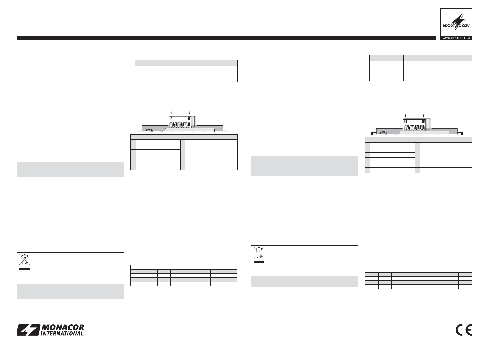
über die 8-polige Buchse auf der Sender-Leiterplatte herstellen:
1 nicht angeschlossen
2 Masse
3 Betriebsspannung +12 V
4 Masse
5 Audioeingang (Line-Pegel)
6 Masse 8 nicht angeschlossen
Die 7-polige Buchse auf der Leiterplatte des POWER-Schalters
wird nicht benötigt.
Kontaktbelegung
Schaltausgang:
Sendemodul Ein → 4V
Sendemodul Aus → 0V
7
(wird für den Betrieb des
Sende moduls nicht benötigt)
4 Bedienung
1) Zum Aufbau der Funkstrecke das Sendemodul noch ausgeschaltet lassen und zuerst den zugehörigen Empfänger auf
einen störungsfreien Übertragungskanal einstellen (
dienungsanleitung des Empfängers). Dann das Sendemodul
mit dem Regler einschalten und über die Tasten auf den gleichen Kanal einstellen. In der Tabelle auf dem Extrablatt finden Sie alle nötigen Informationen zur Bedienung.
Bitte beachten: An der Aktivbox, in die das Sendemodul eingebaut
wurde, müssen Sendemodul und Empfangsmodul auf unterschiedliche Ka näle eingestellt werden, anderenfalls treten Rückkopplungen auf.
2) Ist die Funkstrecke aufgebaut, mit dem Regler die ge wünschte Lautstärke für das gesendete Audiosignal ein stellen.
Be -
5 Technische Daten
1 2 3 4 5 6 7 8
863,1
9 10 11 12 13 14 15 16
863,2 864,2 863,7 864,7 863,4 864,4 863,9 864,9
Übertragungsreichweite: ca. 30 m
Funkfrequenzen in MHz (16 Kanäle)
864,1 863,6 864,6 863,3 864,3 863,8 864,8
Sendeleistung: . . . . . . . . ≤ 10 mW
Stromversorgung: . . . . . 12 V/140 mA
Abmessungen, Gewicht: 191 × 43 × 103mm (B × H × T), 220 g
Änderungen vorbehalten.
Multi-Frequency Transmission Module
These instructions are intended for experts (installation)
and for users without any technical knowledge (operation).
English
Please read these instructions carefully prior to operating
the module and keep them for later reference.
1 Applications
This transmission module can be used for wireless transmission of audio signals to a receiver matched to the same radio
frequencies (e. g. receiving module of an active speaker system
of the series TXA-1020, TXA-1000 or TXA-800). The module is
especially designed for installation into an active speaker system of the series TXA-1020 (for replacing the transmission
module or for retrofitting) but may also be installed into other
units.
Conformity and approval:
Herewith, MONACOR INTERNATIONAL declare that the transmission module TXA-1020MT is in accordance with the basic
requirements and the other relevant regulations of the directive
2014/53/ EU. The declaration of conformity is available on
request from MONACOR INTERNATIONAL. The transmission
module is licence-free and generally approved for operation in
EU and EFTA countries.
Do not make any modifications to the printed circuit board of
the transmitter or to the antenna (black cable)! The modification will render the approval of the module invalid and the
guarantee will become null and void.
2 Important Notes
The module corresponds to all relevant directives of the EU and
is therefore marked with
G
The module is suitable for indoor use only. Protect it against
dripping water and splash water, high air humidity and heat
(admissible ambient temperature range 0 – 40°C).
G
For cleaning the front, only use a dry, soft cloth; never use
water or chemicals.
G
No guarantee claims for the module and no liability for any
resulting personal damage or material damage will be
accepted if the module is used for other purposes than originally intended, if it is not correctly installed or operated, or if it
is not repaired in an expert way.
If the module is to be put out of operation definitively,
take it to a local recycling plant for a disposal which
is not harmful to the environment.
3 Installation
The unit into which the module is to be inserted must be
switched off and disconnected from the mains!
Installation into an active speaker system of the series
TXA-1020:
At the active speaker system, replace the POWER switch module with the module TXA-1020MT:
1) Screw off the POWER switch module, carefully remove it
from its compartment and disconnect its plug connection(s).
.
2) Connect the module TXA-1020MT to the active speaker system:
Active speaker system TXA-1020MT
8-pole plug 8-pole jack on the printed circuit board of the
7-pole plug 7-pole jack on the printed circuit board of the
3) Insert the module into the compartment and fasten it using
screws.
transmitter
POWER switch
Installation into another unit:
Make sure to observe the CE directives. Establish the connection via the 8-pole jack on the printed circuit board of the transmitter:
1 Not connected
2 Ground
3 Operating voltage +12V
4 Ground
5 Audio input (line level)
6 Ground 8 Not connected
The 7-pole jack on the printed circuit board of the POWER
switch is not required.
Pin configuration
Switching output:
transmission module On → 4 V
transmission module Off → 0 V
7
(not required for operating the
transmission module)
4 Operation
1) To establish the transmission path, do not switch on the
transmission module for the time being; first, set the appropriate re ceiver to an interference-free transmission channel
(
op erating instructions of the receiver). Then switch on
the transmission module with the control and use the buttons
to set it to the same channel. All the required information concerning module operation can be found in the table on the
separate sheet.
Please note: At the active speaker system into which the transmission module has been installed, the transmission module and the
receiving module must be set to different channels; otherwise there
will be feedback.
2) When the transmission path has been established, use the
control to adjust the volume of the audio signal transmitted.
5 Specifications
1 2 3 4 5 6 7 8
863.1
9 10 11 12 13 14 15 16
863.2 864.2 863.7 864.7 863.4 864.4 863.9 864.9
Transmission range: . . approx. 30 m
Transmitting power: . .
Power supply: . . . . . . 12 V/140 mA
Dimensions, weight: . .
Subject to technical modification.
Radio frequencies in MHz (16 channels)
864.1 863.6 864.6 863.3 864.3 863.8 864.8
≤ 10 mW
191 × 43 × 103 mm (W × H × D), 220 g
Page 2
®
MONACOR INTERNATIONAL GmbH & Co. KG • Zum Falsch 36 • 28307 Bremen • Germany Copyright©by MONACOR INTERNATIONAL. All rights reserved. A-1629.99.01.02.2015
TXA-1020MT Bestellnummer 17.4640
ELECTRONICS FOR SPECIALISTS ELECTRONICS FOR SPECIALISTS ELECTRONICS FOR SPECIALISTS ELECTRONICS FOR SPECIALISTS ELECTRONICS FOR SPECIALISTS ELECTRONICS FOR SPECIALISTS ELECTRONICS FOR SPECIALISTS ELECTRONICS FOR SPECIALISTS ELECTRONICS FOR SPECIALISTS ELECTRONICS FOR SPECIALISTS ELECTRONICS FOR SPECIALISTS
Modulo trasmettitore multifrequenza
Queste istruzioni sono rivolte sia ad esperti (montaggio)
che a persone senza conoscenze tecniche specifiche (funzionamento). Vi preghiamo di leggerle attentamente prima
della messa in funzione e di conservarle per un uso futuro.
1 Possibilità d'impiego
Con questo modulo trasmettitore è possibile trasmettere in
modo wireless dei segnali audio a un ricevitore sintonizzato
sulle stesse radiofrequenze (p. es. modulo di ricezione di una
cassa attiva della serie TXA-1020, TXA-1000 o TXA-800). Il
modulo è previsto in modo particolare per il montaggio in una
cassa attiva della serie TXA-1020 (come ricambio o integrazione), ma può essere montato anche in un altro apparecchio.
Conformità e omologazione
La MONACOR INTERNATIONAL dichiara che il modulo trasmettitore TXA-1020MT è conforme a tutti i requisiti di base e
alle rimanenti disposizioni in materia della direttiva 2014 / 53/UE.
La dichiarazione di conformità può essere richiesta presso
MONACOR INTERNATIONAL. Il modulo trasmettitore è omologato per l'impiego negli stati dell'UE e dell'EFTA e non
richiede né registrazione né pagamento di tasse.
2 Avvertenze importanti per l'uso
Il modulo è conforme a tutte le direttive rilevanti dellʼUE e pertanto porta la sigla
.
G
Il modulo è previsto solo per lʼuso allʼinterno di locali. Proteggerlo dall'acqua gocciolante e dagli spruzzi d'acqua, da alta
umidità dell'aria e dal calore (temperatura dʼimpiego ammessa fra 0 e 40 °C).
G
Per la pulizia del frontale usare solo un panno morbido,
asciutto; non impiegare in nessun caso acqua o prodotti chimici.
G
Nel caso dʼuso improprio, di montaggio non a regola dʼarte,
dʼimpiego scorretto o di riparazione non a regola dʼarte del
modulo, non si assume nessuna responsabilità per eventuali
danni consequenziali a persone o a cose e non si assume
nessuna garanzia per il modulo.
3 Montaggio
Montaggio in una cassa attiva della serie TXA-1020:
Sulla cassa attiva sostituire l'unità con l'interruttore principale
POWER con il modulo TXA-1020MT:
1) Svitare l'unità con l'interruttore principale, toglierla delicatamente dal vano e staccare la connessione / le connessioni.
L'apparecchio nel quale si deve montare il modulo, deve
assolutamente essere spento e staccato dalla tensione di
rete!
Se si desidera eliminare il modulo definitivamente,
consegnarlo per lo smaltimento ad un'istituzione
locale per il riciclaggio.
Non modificare la scheda trasmettitore o l'antenna (cavo
nero)! La garanzia si annulla e il modulo trasmettitore perde
l'omologazione.
2) Collegare il modulo TXA-1020MT con la cassa attiva:
3) Inserire il modulo nel vano e avvitarlo.
Montaggio in un altro apparecchio:
Si devono rispettare le direttive CE. Effettuare il collegamento
tramite la presa a 8 poli del circuito stampato trasmettitore:
La presa a 7 poli sul c.s. dell'interruttore POWER non serve.
4 Funzionamento
1) Per creare un sistema di trasmissione lasciare ancora
spento il modulo trasmettitore e impostare dapprima sul relativo ricevitore un canale di trasmissione senza interferenze
(
Istruzioni del ricevitore). Quindi accendere il modulo trasmettitore con il regolatore e impostare il medesimo canale
per mezzo dei tasti. Nella tabella sul foglio a parte troverete
tutte le informazioni necessarie.
Da notare: Sulla cassa attiva nella quale è stato montato il modulo
trasmettitore, il modulo trasmettitore e il modulo ricevitore devono
essere impostati su canali differenti, altrimenti si manifestano dei
feedback.
2) Quando il sistema di trasmissione è pronto, impostare con il
regolatore il volume per il segnale audio trasmesso.
5 Dati tecnici
Portata di trasmissione: ca. 30 m
Potenza di trasmissione:
≤ 10 mW
Alimentazione: . . . . . . . 12 V
/140 mA
Dimensioni, peso: . . . . . 191 × 43 × 103 mm (l × h × p), 220 g
Con riserva di modifiche tecniche.
Radiofrequenze in MHz (16 canali)
1 2 3 4 5 6 7 8
863,1
864,1 863,6 864,6 863,3 864,3 863,8 864,8
9 10 11 12 13 14 15 16
863,2 864,2 863,7 864,7 863,4 864,4 863,9 864,9
Piedinatura
1 Non collegato
7
Uscita di commutazione:
Modulo trasmettitore ON → 4V
Modulo trasmettitore OFF → 0V
(non è richiesto per l'uso
del modulo trasmettitore)
2 Massa
3 Tensione d'esercizio +12 V
4 Massa
5 Ingresso audio (livello Line)
6 Massa 8 Non collegato
Cassa attiva TXA-1020MT
Connettore a 8 poli Presa a 8 poli sulla scheda c.s. trasmettitore
Connettore a 7 poli Presa a 7 poli sulla scheda c.s. dell'interruttore
POWER
Module émetteur multifréquences
Cette notice sʼadresse aux professionnels (installateurs) et
personnes sans connaissances techniques spécifiques
(opérateurs). Veuillez lire la présente notice avec attention
avant le fonctionnement et conservez-la pour pouvoir vous
y reporter ultérieurement.
1 Possibilités dʼutilisation
Avec ce module émetteur, on peut transmettre des signaux
audio sans fil vers un récepteur réglé sur les mêmes fréquences (par exemple module de réception dʼune enceinte
active de la série TXA-1020, TXA-1000 ou TXA-800). Le
module est conçu pour une installation dans une enceinte
active de la série TXA-1020 (pour compléter le système ou pour
remplacer le module émetteur), il peut également être installé
dans un autre appareil.
Conformité et autorisation :
Par la présente, MONACOR INTERNATIONAL déclare que le
module émetteur TXA-1020MT se trouve en conformité avec
les exigences fondamentales et les réglementations inhérentes
à la directive 2014 / 53 / UE. La déclaration de conformité peut
être demandée auprès de MONACOR INTERNATIONAL. Le
module émetteur est autorisé pour un fonctionnement dans les
pays de l'Union européenne et de l'A.E.L.E. et ne nécessite
pas de déclaration.
2 Conseils importants dʼutilisation
Le module répond à toutes les directives nécessaires de
l'Union européenne et porte donc le symbole
.
G
Le module n'est conçu que pour une utilisation en intérieur.
Protégez-le des éclaboussures, de tout type de projections
d'eau, d'une humidité élevée de lʼair et de la chaleur (plage de
température de fonctionnement autorisée : 0 – 40°C).
G
Pour nettoyer le front, utilisez uniquement un chiffon sec et
doux, en aucun cas, de produits chimiques ou d'eau.
G
Nous déclinons toute responsabilité en cas de dommages
matériels ou corporels consécutifs si le module est utilisé
dans un but autre que celui pour lequel il a été conçu, s'il n'est
pas correctement installé ou utilisé ou sʼil n'est pas réparé par
une personne habilitée ; en outre, la garantie deviendrait
caduque.
3 Installation
Installation dans une enceinte active de la série TXA-1020 :
Sur lʼenceinte active, remplacez le module POWER par le
module TXA-1020MT :
Lʼappareil dans lequel le module doit être installé doit impérativement être éteint et débranché du secteur.
Lorsque le module est définitivement retiré du service, vous devez le déposer dans une usine de recyclage adaptée pour contribuer à son élimination non
polluante.
Ne faites aucunes modifications sur le circuit imprimé de
lʼémetteur ou sur lʼantenne (câble noir). La garantie devient
caduque et le module émetteur perd son autorisation.
1) Dévissez le module POWER, retirez-le avec précaution du
tiroir et défaites le(s) branchemen(s).
2) Reliez le module TXA-1020MT à lʼenceinte active :
3) Placez le module dans le tiroir et vissez-le.
Installation dans un autre appareil :
Respectez les directives CE. Etablissez les branchements via
la prise 8 pôles sur le circuit imprimé de lʼémetteur :
La prise 7 pôles sur le circuit imprimé de lʼinterrupteur POWER
nʼest pas nécessaire.
4 Utilisation
1) Pour établir la voie sans fil, laissez le module émetteur éteint
et tout dʼabord réglez le récepteur correspondant sur un
canal de transmission sans interférences (
notice dʼutilisation du récepteur). Ensuite allumez le module émetteur
avec le réglage et via les touches, réglez-le sur le même
canal. Vous trouverez toutes les informations nécessaires
relatives au fonctionnement du module dans le tableau sur la
feuille séparée.
Attention : sur lʼenceinte active dans laquelle le module émetteur a
été intégré, il faut que le module émetteur et le module de réception
soient réglés sur des canaux différents, sinon il y a risque dʼeffets
de larsen.
2) Lorsque la voie sans fil est établie, réglez le volume pour le
signal audio émis avec le réglage.
5 Caractéristiques techniques
Portée transmission : . . 30 m env.
Puissance dʼémission : . ≤ 10 mW
Alimentation : . . . . . . . . 12 V
/140 mA
Dimensions, poids : . . . 191
×
43 ×103 mm (L ×H×P), 220 g
Tout droit de modification réservé.
Fréquences radio en MHz (16 canaux)
1 2 3 4 5 6 7 8
863,1
864,1 863,6 864,6 863,3 864,3 863,8 864,8
9 10 11 12 13 14 15 16
863,2 864,2 863,7 864,7 863,4 864,4 863,9 864,9
Configuration des contacts
1 non connecté
7
sortie commutation :
module émetteur allumé → 4V
module émetteur éteint → 0V
(pas nécessaire pour faire
fonctionner le module)
2 masse
3 tension fonctionnement +12 V
4 masse
5 entrée audio (niveau ligne)
6 masse 8 non connecté
Enceinte active TXA-1020MT
fiche 8 pôles prise 8 pôles sur le circuit imprimé de l’émetteur
fiche 7 pôles prise 7 pôles sur le circuit imprimé de l’interrup-
teur POWER
Français
Italiano
Page 3

TXA-1020MT Bestellnummer 17.4640
ELECTRONICS FOR SPECIALISTS ELECTRONICS FOR SPECIALISTS ELECTRONICS FOR SPECIALISTS ELECTRONICS FOR SPECIALISTS ELECTRONICS FOR SPECIALISTS ELECTRONICS FOR SPECIALISTS ELECTRONICS FOR SPECIALISTS ELECTRONICS FOR SPECIALISTS ELECTRONICS FOR SPECIALISTS ELECTRONICS FOR SPECIALISTS ELECTRONICS FOR SPECIALISTS
Multifrequentie-zendmodule
Deze handleiding is zowel voor vakmensen (inbouw)
bedoeld als voor personen zonder technische vakkennis
(bediening). Lees de handleiding grondig door, alvorens
het apparaat in gebruik te nemen, en bewaar ze voor
latere raadpleging.
Nederlands
1 Toepassingen
Met deze zendmodule kunt u audiosignalen draadloos naar
een ontvanger sturen die op dezelfde radiofrequenties afgestemd is (bv. ontvangstmodule van een actieve luidspreker van
de serie TXA- 1020, TXA-1000 of TXA-800). De module is speciaal ontworpen voor inbouw in een actieve luidspreker van de
serie TXA- 1020 (als reserveonderdeel of voor de aanpassing),
maar kan ook in een ander apparaat worden ingebouwd.
Conformiteit en goedkeuring:
Hiermee verklaart MONACOR INTERNATIONAL dat de zendmodule TXA-1020MT in overeenstemming is met de fundamentele eisen en de overige van toepasselijke bepalingen van
de richtlijn 2014 / 53 / EU. De verklaring van overeenstemming
kan bij MONACOR INTERNATIONAL worden aangevraagd.
Het gebruik van de zendmodule is algemeen toegelaten in de
Lidstaten van de EU en de EFTA, en is vrij van registratie en
van heffingen.
Voer geen wijzigingen door aan de printplaat van de zender of
aan de antenne (zwarte kabel)! De garantie vervalt en de
zendmodule verliest haar registratie.
2 Belangrijke gebruiksvoorschriften
De module is in overeenstemming met alle relevante EU-Richtlijnen en draagt daarom de
G
De module is enkel geschikt voor gebruik binnenshuis. Vermijd druip- en spatwater, uitzonderlijk warme plaatsen en
plaatsen met een hoge vochtigheid (toegestaan omgevingstemperatuurbereik 0 – 40°C).
G
Gebruik voor de reiniging van het frontpaneel uitsluitend een
droge, zachte doek. Gebruik in geen geval chemicaliën of
water.
G
In geval van ongeoorloofd of verkeerd gebruik, ondeskundige
montage, foutieve bediening of van herstelling door een nietgekwalificeerd persoon vervalt de garantie en de aansprakelijkheid voor hieruit resulterende materiële of lichamelijke
schade.
Wanneer de module definitief uit bedrijf genomen
wordt, bezorg ze dan voor milieuvriendelijke verwerking aan een plaatselijk recyclagebedrijf.
-markering.
3 Montage
Het apparaat waar de module in moet worden gemonteerd,
moet in elk geval worden uitgeschakeld en van de netspanning losgekoppeld!
Montage in een actieve luidspreker van de serie TXA-1020:
Op de actieve luidspreker vervangt u de eenheid met de hoofdschakelaar POWER door de module TXA-1020MT:
®
MONACOR INTERNATIONAL GmbH & Co. KG • Zum Falsch 36 • 28307 Bremen • Germany Copyright©by MONACOR INTERNATIONAL. All rights reserved. A-1629.99.01.02.2015
1) Schroef de hoofdschakelaareenheid los, haal deze voorzichtig uit de schacht en maak de steekverbinding(en) los.
2) Sluit de module TXA-1020MT aan op de actieve luidspreker:
Actieve luidspreker TXA-1020MT
8-polige stekker 8-polige bus op de zenderprintplaat
7-polige stekker 7-polige bus op de printplaat van de
POWER-schakelaar
3) Plaats de module in opening en schroef vast.
Montage in een ander apparaat:
De CE-richtlijnen moeten in acht genomen worden. Breng de
aansluiting via de 8-polige bus op de zenderprintplaat tot stand:
1 niet aangesloten
2 massa
3 bedrijfsspanning +12 V
4 massa
5 audio-ingang (lijnniveau)
6 massa 8 niet aangesloten
De 7-polige bus op de printplaat van de POWER-schakelaar
wordt niet gebruikt.
Penconfiguratie
schakeluitgang:
zendmodule Aan → 4V
zendmodule Uit → 0V
7
(niet nodig voor werking
van de zendmodule)
4 Bediening
1) Om de radioverbinding tot stand te brengen, laat u de zendmodule nog uitgeschakeld en stel eerst de bijbehorende ontvanger in op een storingvrij transmissiekanaal (
ningshandleiding van de ontvanger). Schakel dan de zendmodule in met de regelaar en stel via de toetsen in op
hetzelfde kanaal. In de tabel op het bijblad vindt u alle nodige
informatie voor de bediening.
Belangrijk: Op de actieve luidspreker waarin de zendmodule werd
ingebouwd, moeten zendmodule en ontvangstmodule op verschillende kanalen worden ingesteld. Anders treden er terugkoppelingen
op.
2) Als de radioverbinding is opgebouwd, stelt u met de regelaar
het gewenste geluidsvolume voor het verzonden audiosignaal in.
Bedie-
5 Technische gegevens
1 2 3 4 5 6 7 8
863,1
9 10 11 12 13 14 15 16
863,2 864,2 863,7 864,7 863,4 864,4 863,9 864,9
Transmissiebereik: . . . . ca. 30 m
Zendvermogen: . . . . . . ≤ 10 mW
Voedingsspanning: . . . . 12 V
Afmetingen, gewicht: . . 191 ×43 × 103 mm (B×H×D), 220g
Wijzigingen voorbehouden.
Radiofrequenties in MHz (16 kanalen)
864,1 863,6 864,6 863,3 864,3 863,8 864,8
/140 mA
Moduł nadajnika
wieloczęstotliwościowego
Polski
Niniejsza instrukcja przeznaczona jest zarówno dla
doświadczonych instalatorów jak i użytkowników nie
posiadających wiedzy technicznej. Przed rozpoczęciem
użytkowania proszę zapoznać się z instrukcją, a następnie
zachować ją do wglądu.
1 Zastosowanie
Niniejszy moduł nadajnika pozwala na bezprzewodowe przesyłanie sygnału audio do odbiorników pracujących na tych
samych częstotliwościach radiowych (np. modułów odbiornika
w przenośnych systemach wzmacniających serii TXA-1020,
TXA-1000 oraz TXA-800). Moduł przeznaczony jest do instalacji w urządzeniach serii TXA-1020 (do rozbudowy lub jako
zamiennik dla wbudowanego modułu odbiornika), ale może być
montowany także w innych urządzeniach.
Zgodności i zezwolenia:
MONACOR INTERNATIONAL deklaruje niniejszym, że moduł
nadajnika TXA-1020MT spełnia wszystkie wymagania normy
2014 / 53 / UE. Deklaracja zgodności dostępna jest na żądanie w
oddziałach firmy MONACOR INTERNATIONAL. Moduł nie
wymaga licencji w krajach należących do EU oraz EFTA.
Nie należy dokonywać żadnych modyfikacji na drukowanej
płytce ani anteny (czarny kabel)! Dokonanie modyfikacji
powoduje utratę możliwości wykorzystywania modułu bez
licencji oraz utratę gwarancji.
2 Środki bezpieczeństwa
Moduł spełnia wszystkie wymagania norm UE dlatego zostało
oznaczone symbolem
G
Moduł przeznaczony jest wyłącznie do użytku wewnątrz
pomieszczeń. Należy chronić go przez wodą, dużą wilgotnością oraz wysoką temperaturą (dopuszczalny zakres wynosi
0 – 40°C).
G
Do czyszczenia używać suchej miękkiej ściereczki; nie używać wody ani środków chemicznych.
G
Producent ani dostawca nie ponoszą odpowiedzialności za
wynikłe szkody: uszkodzenie sprzętu lub obrażenia użytkownika, jeśli urządzenie było używane niezgodnie z przeznaczeniem, zostało nieprawidłowo zamontowane, podłączone
lub obsługiwane bądź poddane nieautoryzowanej naprawie.
Po całkowitym zakończeniu eksploatacji, urządzenie należy oddać do punktu recyklingu, aby nie
zaśmiecać środowiska.
3 Instalacja
Bezwzględnie odłączyć zasilanie urządzenia, w którym ma
być zamontowany moduł!
Instalacja w przenośnych systemach wzmacniających
serii TXA-1020:
Moduł TXA-1020MT należy zamontować w miejscu modułu z
włącznikiem POWER:
.
1) Odkręcić moduł z włącznikiem POWER, ostrożnie wysunąć
go z komory i odłączyć wtyk(i) kabli połączeniowych.
2) Podłączyć moduł TXA-1020MT do urządzenia:
Urządzenie TXA-1020MT
8-pinowy wtyk 8-pinowe gniazdo na drukowanej płytce nadajnika
7-pinowy wtyk
7-pinowe gniazdo na drukowanej płytce włącznika
POWER
3) Wsunąć moduł do komory i przykręcić go śrubami.
Instalacja w innym urządzeniu:
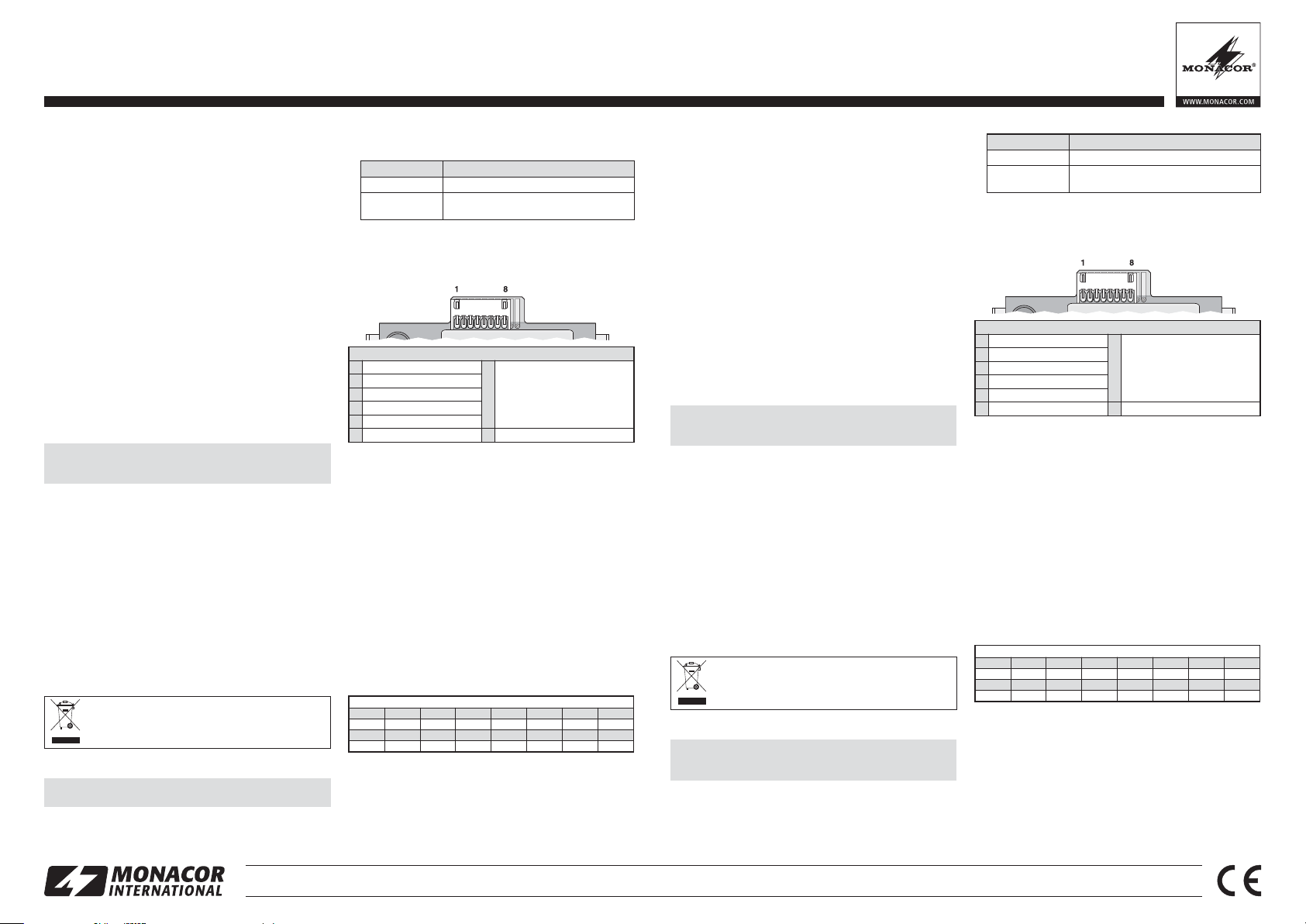
Zapoznać się z wymaganiami CE danego urządzenia. Podłączanie modułu odbywa się poprzez 8-pinowe gniazdo na drukowanej płytce nadajnika:
1
Nie używany
2
Masa
3
Napięcie zasilania +12 V
4
Masa
5
Wejście audio (poziom liniowy)
6
Masa
Podłączenie 7-pinowego gniazda na drukowanej płytce włącznika POWER nie jest wymagane.
Konfiguracja pinów
Wyjście przełączające:
moduł nadajnika wł.→4V
7
moduł nadajnika wył.→0V
(nie wymagane do pracy nadajnika)
8
Nie używany
4 Obsługa
1) Aby ustanowić połączenie, początkowo nie włączać modułu
nadajnika; w pierwszej kolejności ustawić wolny od zakłóceń
i innych sygnałów kanał transmisji na odbiorniku (
cja obsługi odbiornika). Następnie włączyć moduł nadajnika
i ustawić go na ten sam kanał, za pomocą przycisków.
Szczegółowe informacje na temat obsługi modułu można
znaleźć w tabeli na osobnej kartce.
Uwaga: W urządzeniu, w którym zamontowano moduł nadajnika,
nadajnik i odbiornik muszą być ustawione na różne kanały, w przeciwnym razie nastąpi sprzężenie.
2) Po nawiązaniu połączenia, ustawić głośność przesyłanego
sygnału audio.
5 Specyfikacja
Częstotliwości radiowe w MHz (16 kanałów)
1 2 3 4 5 6 7 8
864,1 863,6 864,6 863,3 864,3 863,8 864,8
863,1
9 10 11 12 13 14 15 16
863,2 864,2 863,7 864,7 863,4 864,4 863,9 864,9
Zasięg transmisji: . . . . . około 30 m
Moc nadajnika: . . . . . . . ≤ 10 mW
Zasilanie: . . . . . . . . . . . 12 V
Wymiary, waga: . . . . . . 191
Z zastrzeżeniem możliwości zmian.
/140 mA
×43×
103 mm (S×W×D), 220 g
instruk-
Page 4

®
MONACOR INTERNATIONAL GmbH & Co. KG • Zum Falsch 36 • 28307 Bremen • Germany Copyright©by MONACOR INTERNATIONAL. All rights reserved. A-1629.99.01.02.2015
TXA-1020MT Bestellnummer 17.4640
ELECTRONICS FOR SPECIALISTS ELECTRONICS FOR SPECIALISTS ELECTRONICS FOR SPECIALISTS ELECTRONICS FOR SPECIALISTS ELECTRONICS FOR SPECIALISTS ELECTRONICS FOR SPECIALISTS ELECTRONICS FOR SPECIALISTS ELECTRONICS FOR SPECIALISTS ELECTRONICS FOR SPECIALISTS ELECTRONICS FOR SPECIALISTS ELECTRONICS FOR SPECIALISTS
4 Funcionamiento
1) Para establecer la vía de transmisión, no conecte todavía el
módulo de transmisión; primero ajuste el receptor apropiado
en un canal de transmisión sin interferencias (
instrucciones de funcionamiento del receptor). Luego conecte el
módulo de transmisión con el control y utilice los botones
para ajustarlo en el mismo canal. Toda la información necesaria referente al funcionamiento del módulo se puede
encontrar en la tabla de la hoja separada.
Tenga en cuenta que: En el recinto activo en el que hay que instalar el módulo de transmisión, hay que ajustar el módulo de transmisión y el módulo de recepción en canales diferentes; de lo contrario habrá feedback.
2) Cuando se haya establecido la vía de transmisión, utilice el
control para ajustar el volumen de la señal de audio transmitida.
5 Especificaciones
Rango de transmisión: . . aprox. 30 m
Potencia de transmisión: ≤ 10 mW
Alimentación: . . . . . . . . . 12 V
/140 mA
Dimensiones, peso: . . . .
191 × 43 × 103 mm(B×H×
P), 220 g
Sujeto a modificaciones técnicas.
Frecuencias de radio en MHz (16 canales)
1 2 3 4 5 6 7 8
863,1
864,1 863,6 864,6 863,3 864,3 863,8 864,8
9 10 11 12 13 14 15 16
863,2 864,2 863,7 864,7 863,4 864,4 863,9 864,9
Módulo de Transmisión Multifrecuencia
Estas instrucciones van dirigidas a expertos (instalación) y
a usuarios sin conocimientos técnicos (funcionamiento).
Lea atentamente estas instrucciones antes de utilizar el
módulo y guárdelas para consultas posteriores.
1 Aplicaciones
Este módulo de transmisión se puede utilizar para la transmisión inalámbrica de señales de audio al receptor adecuado con
las mismas frecuencias de radio (p. ej. módulo receptor de un
recinto activo de la gama TXA-1020, TXA-1000 o TXA-800). El
módulo está diseñado especialmente para instalarse en un
recinto activo de la gama TXA-1020 (para sustituir el módulo de
transmisión o para retroadaptación) pero se puede instalar en
otros aparatos.
Conformidad y aprobación:
Por la presente, MONACOR INTERNATIONAL declara que el
módulo de transmisión TXA-1020MT cumple con los requisitos
básicos y las demás regulaciones relevantes de la directiva
2014 / 53 / UE. La declaración de conformidad está disponible
bajo petición en MONACOR INTERNATIONAL. El módulo de
transmisión no requiere ninguna licencia y está aprobado
para el funcionamiento en la UE y en los países de la AELC.
2 Notas Importantes
El módulo cumple con todas las directivas relevantes de la UE
y por lo tanto está marcado con el símbolo
.
G
El módulo está adecuado sólo para utilizarlo en interiores.
Protéjalo de goteos y salpicaduras, elevada humedad del
aire y calor (temperatura ambiente admisible: 0 – 40ºC).
G
Para limpiar el frontal, utilice sólo un paño suave y seco; no
utilice nunca ni agua ni productos químicos.
G
No podrá reclamarse garantía o responsabilidad alguna por
cualquier daño personal o material resultante si el módulo se
utiliza para otros fines diferentes a los originalmente concebidos, si no se instala o no se utiliza adecuadamente o si no
se repara por expertos.
Si va a poner el módulo definitivamente fuera de servicio, llévelo a la planta de reciclaje más cercana
para que su eliminación no sea perjudicial para el
medioambiente.
¡No haga ninguna modificación en la placa del circuito
impreso del emisor o en la antena (cable negro)! La modificación rescindiría la aprobación del módulo inválido y la garantía quedaría anulada y sin efecto.
3 Instalación
Instalación en un recinto activo de la gama TXA-1020:
En el recinto activo, cambie el módulo interruptor POWER por
el módulo TXA-1020MT:
1) Desatornille el módulo interruptor POWER, quitándolo con
cuidado de su compartimento y desconecte su(s) conexión(es).
2) Conecte el módulo TXA-1020MT al recinto activo:
3) Inserte el módulo en el compartimento y fíjelo utilizando tornillos.
Instalación en otro aparato:
Asegúrese de prestar atención a las directivas de la UE. Establezca la conexión mediante la toma de 8 polos de la placa del
circuito impreso del emisor:
No se necesita la toma de 7 polos de la placa del circuito
impreso del interruptor POWER.
Configuración de pines
1 No conectado
2 Masa
3 Voltaje de funcionamiento +12 V
4 Masa
5 Entrada de audio (nivel de línea)
6 Masa
7
Salida de conmutación:
Módulo de transmisión conectado → 4V
Módulo de transmisión desconectado → 0V
(no se necesita para utilizar el módulo de transmisión)
8 No conectado
¡El aparato en el que hay que insertar el módulo debe apagarse y desconectarse de la corriente!
Recinto activo TXA-1020MT
Conector de 8 polos Toma de 8 polos en la placa del circuito impreso
del emisor
Conector de 7 polos Toma de 7 polos en la placa del circuito impreso
del interruptor POWER
Español
Page 5

Deutsch English
Français
Italiano
Funktionen der Bedienelemente Functions of the operating elements Fonctions des éléments de commande Funzioni degli elementi di comando
Display zur Anzeige des Übertragungskanals
(CH 1 … CH 16)
Sendeanzeige;
leuchtet bei eingeschaltetem Sendemodul
Pegelanzeigen für das Audiosignal am Eingang des
Sendemoduls
gelbe LED: leuchtet ab einem bestimmten Mindestpegel
rote LED: Übersteuerungsanzeige, sollte höchstens
bei Signalspitzen kurz aufleuchten; leuchtet sie permanent, die Lautstärke der jeweiligen Tonquelle/n
reduzieren
Tasten zur Einstellung des Übertragungskanals:
1. Die Taste SET drücken: Die Kanalanzeige im Display blinkt.
2. Solange die Kanalanzeige blinkt (10 Sek. lang),
kann mit den Pfeiltasten der Kanal gewählt werden.
3. Die Kanalwahl mit der Taste SET bestätigen
(anderenfalls schaltet das Sendemodul nach
10 Sekunden zurück auf den vorher eingestellten
Kanal).
Um sich während des Betriebs kurz die Funkfrequenz anzeigen zu lassen, eine der Pfeiltasten
gedrückt halten: Das Display zeigt solange statt des
Kanals die Frequenz an.
Ein-/Ausschalter und Lautstärkeregler des Sendemoduls
Display to indicate the transmission channel
(CH 1 … CH 16)
Transmission indicator; will light up when the transmitting module is switched on
Level indicators for the audio signal at the input of the
transmitting module:
yellow LED: will light up when a specific minimum
level has been reached
red LED: overload indicator, should only light up
briefly for signal peaks; if it lights up continuously,
reduce the volume of the respective audio source(s)
Buttons for setting the transmission channel:
1. Press the button SET: The channel indication on
the display will start flashing.
2. As long as the channel indication flashes (10 sec.),
the arrow buttons can be used to select the channel.
3. Confirm the selected channel with the button SET
(otherwise, the transmitting module will return to
the previously set channel after 10 seconds).
To briefly indicate the radio frequency during operation, keep one of the arrow buttons pressed: The display will indicate the frequency instead of the channel while the arrow button is pressed.
Power switch and volume control of the transmitting
module
Affichage pour le canal de transmission
(CH 1 … CH 16)
Indication dʼémission ;
brille lorsque le module dʼémission est allumé
Indications de niveau pour le signal audio à lʼentrée
du module dʼemission :
LED jaune : brille à partir dʼun niveau minimal donné
LED rouge : affichage de surcharge : devrait briller
brièvement pour des pointes de signal ; si elle brille
en continu, diminuez le volume de la source (des
sources) correspondante(s)
Touches pour régler le canal de transmission :
1. Appuyez sur la touche SET : lʼindication de canal
sur lʼaffichage clignote.
2. Tant que lʼindication de canal clignote (pendant
10 secondes), vous pouvez sélectionner le canal
avec les touches flèches.
3. Confirmez la sélection de canal avec la touche
SET (sinon le module dʼémission revient sur le
canal précédemment réglé après 10 secondes).
Pour afficher brièvement la fréquence radio pendant
le fonctionnement, maintenez une des touches
flèche enfoncée : lʼaffichage indique la fréquence au
lieu du canal.
Interrupteur marche / arrêt et réglage de volume du
module émetteur
Display per visualizzare il canale di trasmissione
(CH 1 … CH 16)
Spia di trasmissione;
è accesa con il modulo trasmettitore attivato
Spie di livello per il segnale audio all'ingresso del
modulo trasmettitore:
LED giallo: è acceso a partire da un determinato
livello minimo
LED rosso: spia di sovrapilotaggio, dovrebbe ac cendersi brevemente al massimo con i picchi del
segnale; se rimane acceso permanentemente oc corre ridurre il volume della relativa fonte audio
Tasti per impostare il canale di trasmissione:
1. Premere il tasto SET: Lampeggia l'indicazione del
canale sul display.
2. Mentre l'indicazione del canale sta lampeggiando
(per 10 sec.), con i tasti freccia si può scegliere il
canale.
3. Confermare la scelta del canale con il tasto SET
(altrimenti, dopo 10 secondi, il modulo trasmet tito re ritorna al canale impostato precedentemente).
Per visualizzare brevemente la radiofrequenza
durante il funzionamento, tener premuto uno dei
tasti freccia: Il display visualizza intanto la frequenza invece del canale.
Interruttore on / off e regolatore volume del modulo
trasmettitore
Wird nur bei Einbau des Moduls in eine Aktivbox der
Serie TXA-1020 benötigt:
Hauptschalter POWER für die Aktivbox und Statusanzeige für die Akkus
Aktivbox
®
Bedienungsanleitung der
MONACOR INTERNATIONAL GmbH & Co. KG • Zum Falsch 36 • 28307 Bremen • Germany Copyright©by MONACOR INTERNATIONAL. All rights reserved. A-1627.99.01.02.2015
Only required when the module is installed into an
active speaker system of the series TXA-1020:
POWER switch for the active speaker system and
status indicators for the rechargeable batteries
operating instructions of the active speaker sys-
tem
Uniquement nécessaire si le module est installé
dans une enceinte active de la série TXA-1020 :
Interrupteur principal POWER pour lʼenceinte active
et indications dʼétat pour les accus,
sation de lʼenceinte active
notice dʼutili-
Solo per il montaggio del modulo in una cassa attiva
della serie TXA-1020:
Interruttore principale POWER per la cassa attiva e
indicazione stato delle batterie
cassa attiva
Istruzioni della
Page 6

®
MONACOR INTERNATIONAL GmbH & Co. KG • Zum Falsch 36 • 28307 Bremen • Germany Copyright©by MONACOR INTERNATIONAL. All rights reserved. A-1627.99.01.02.2015
Functies van de bedieningselementen Funkcje elementów sterujących Funciones de los elementos de funcionamiento
Display voor de weergave van het transmissiekanaal
(CH 1 … CH 16)
Wskaźnik kanału transmisyjnego
(CH 1 … CH 16)
Visualizador para indicar el canal de transmisión
(CH 1 … CH 16)
Zenderled; licht op bij ingeschakelde zendmodule Wskaźnik nadajnika: świeci się przy włączonym nadaj-
niku
Indicador de transmisión; se iluminará cuando se co necte el módulo de transmisión
Niveauleds voor het audiosignaal op de ingang van de
zendmodule:
gele led: licht op vanaf een bepaald minimumniveau
rode led: oversturingsled, mag slechts bij signaalpieken
kort oplichten; als ze permanent oplicht, verminder dan
het geluidsvolume van de respectieve geluidsbron(nen)
Diodowy wskaźnik AF LEVEL poziomu sygnału na wejściu modułu nadajnika:
żółta dioda: zapala się po osiągnięciu poziomu minimalnego
czerwona dioda: zapala się po osiągnięciu poziomu
maksymalnego; powinna zapalać się wyłącznie przy wartościach szczytowych sygnału, jeżeli świeci ciągle należy
zredukować głośność odpowiedniego źródła sygnału
Indicadores de nivel de la señal de audio en la entrada
del módulo de transmisión:
LED amarillo: Se iluminará cuando se alcance un nivel
mínimo específico
LED rojo: Indicador de sobrecarga, sólo debería iluminarse brevemente para picos de señal; si se ilumina
continuamente, reduzca el volumen de la(s) fuente(s) de
audio correspondiente(s)
Toetsen voor het instellen van het transmissiekanaal:
1. Druk op de toets SET: De kanaalaanduiding op het display knippert.
2. Zolang de kanaalaanduiding knippert (10 sec lang)
kunt u met de pijltoetsen het kanaal selecteren.
3. Bevestig de kanaalkeuze met toets SET (anders schakelt de zendmodule na 10 sec terug naar het tevoren
ingestelde kanaal).
Om tijdens het bedrijf kort de radiofrequentie te kunnen
bekijken, houdt u een van de pijltoetsen ingedrukt: Gedurende deze tijd verschijnt de frequentie in plaats van het
kanaal op het display.
Przycisk SET do ustawiania kanału transmisji:
1. Wcisnąć przycisk SET: Wskazanie kanału na wyświetlaczu zacznie migać.
2. Tak długo jak wskazanie kanału miga (10sek.), można
wybrać kanał, za pomocą przycisków ze strzałkami.
3. Potwierdzić wybór kanału przyciskiem SET (jeżeli
wybór nie zostanie potwierdzony w ciągu 10 sekund,
urządzenie powróci do poprzedniego ustawienia).
Można na krótko wyświetlić częstotliwość dla wybranego
kanału: należy przytrzymać wciśnięty jeden z przycisków
ze strzałką.
Botones para ajustar el canal de transmisión:
1. Pulse el botón SET: La indicación de canal empezará
a parpadear en el visualizador.
2. Mientras parpadee la indicación de canal (10 seg.), se
podrán utilizar los botones de flecha para seleccionar
el canal.
3. Confirme el canal seleccionado con el botón SET (de
lo contrario, el módulo de transmisión volverá al canal
ajustado previamente después de 10 segundos).
Para indicar brevemente la frecuencia de radio durante el
funcionamiento, mantenga pulsado uno de los botones
de flecha: El visualizador indicará la frecuencia en lugar
del canal mientras el botón de flecha esté pulsado.
POWER-schakelaar en volumeregelaar van de zendmodule
Włącznik z regulatorem głośności nadawanego sygnału Interruptor Power y control de volumen del módulo de
transmisión
Is alleen noodzakelijk bij de inbouw van de module in een
actieve luidspreker van de serie TXA-1020:
hoofdschakelaar POWER voor de actieve luidspreker en
statusweergave voor de accu's
Bedieningshandlei-
ding van de actieve luidspreker
Wymagane tylko w przypadku montażu modułu w przenośnych systemach wzmacniających serii TXA-1020:
Włącznik POWER przenośnego systemu wzmacnia jącego oraz wskaźnik stanu baterii akumulatorowych
instrukcja obsługi systemu wzmacniającego
Necesario sólo cuando se ha instalado el módulo en un
recinto activo de la gama TXA-1020:
Interruptor POWER del recinto activo y los indicadores
de estado de las baterías recargables
instrucciones
de funcionamiento del recinto activo
Nederlands
Polski
Español
 Loading...