

Page 1

BEDIENUNGSANLEITUNG
INSTRUCTION MANUAL
MODE D’EMPLOI
ISTRUZIONI PER L’USO
GEBRUIKSAANWIJZING
MANUAL DE INSTRUCCIONES
BRUGSANVISNING
BRUKSANVISNING
KÄYTTÖOHJE
CCTV-FARBKAMERA IN EINKABELTECHNIK
CCTV-COLOUR-CAMERA IN ONE-CABLE TECHNIQUE
TVCCD-160SCOL
Best.-Nr. 19.3950
®
Page 2
2
Bevor Sie einschalten …
Wir wünschen Ihnen viel Spaß mit Ihrem neuen
Gerät von MONACOR. Bitte lesen Sie die Bedienungsanleitung vor dem Betrieb gründlich durch.
Nur so lernen Sie alle Funktionsmöglichkeiten
kennen, vermeiden Fehlbedienungen und schützen sich und Ihr Gerät vor eventuellen Schäden
durch unsachgemäßen Gebrauch. Heben Sie die
Anleitung für ein späteres Nachlesen auf.
Der deutsche Text beginnt auf der Seite 4.
D
A
CH
Avant toute installation …
Nous vous souhaitons beaucoup de plaisir à utiliser cet appareil MONACOR. Lisez ce mode
d'emploi entièrement avant toute utilisation. Uniquement ainsi, vous pourrez apprendre l’ensemble des possibilités de fonctionnement de l’appareil, éviter toute manipulation erronée et vous
protéger, ainsi que l’appareil, de dommages
éventuels engendrés par une utilisation inadaptée. Conservez la notice pour pouvoir vous y
reporter ultérieurement.
La version française se trouve page 8.
Antes de la utilización …
Le deseamos una buena utilización para su nuevo aparato MONACOR. Por favor, lea estas instrucciones de uso atentamente antes de hacer
funcionar el aparato. De esta manera conocerá
todas las funciones de la unidad, se prevendrán
errores de operación, usted y el aparato estarán
protegidos en contra de todo daño causado por
un uso inadecuado. Por favor, guarde las instrucciones para una futura utilización.
El texto en español empieza en la página 14.
Før du tænder …
Tillykke med dit nye MONACOR produkt. Læs
venligst betjeningsvejlledningen inden du tager
enheden i brug. Kun på denne måde, lære du
alle funktionerne at kende og at der opstår skader på enheden, som følge af forkert brug. Gem
venligst denne vejlledning til senere brug.
Den danske tekst starter på side 16.
DK
Before switching on …
We wish you much pleasure with your new
MONACOR unit. Please read these operating
instructions carefully prior to operating the unit.
Thus, you will get to know all functions of the unit,
operating errors will be prevented, and yourself
and the unit will be protected against any
damage caused by improper use. Please keep
the operating instructions for later use.
The English text starts on page 6.
E
GB
I
S
Prima di accendere …
Vi auguriamo buon divertimento con il vostro
nuovo apparecchio di MONACOR. Leggete
attentamente le istruzioni prima di mettere in
funzione l'apparecchio. Solo così potete conoscere tutte le funzionalità, evitare comandi sbagliati e proteggere voi stessi e l'apparecchio da
eventuali danni in seguito ad un uso improprio.
Conservate le istruzioni per poterle consultare
anche in futuro.
Il testo italiano inizia a pagina 10.
Innan du slår på enheten
Vi önskar dig mycket glädje med din nya
MONACOR produkt. Läs igenom Instruktionerna
innan enheten tas i bruk. Detta för att undvika
problem då enheten används samt undvika skador på enheten eller de personer som använder
den. Spar bruksanvisningen för framtida bruk.
Den svenska texten börjar på sidan 18.
FIN
Ennen kytkemistä …
T oivomme Sinulle paljon miellyttäviä hetkiä uuden
MONACOR laitteen kanssa. Ole hyvä ja lue käyttöohjeet ennen laitteen käyttöönottoa. Luettuasi
käyttöohjeet voit käyttää laitetta turvallisesti ja
vältyt laitteen väärinkäytöltä. Ole hyvä ja säilytä
käyttöohjeet myöhempää käyttöä varten.
Käyttöohjeet löydät sivulta 20.
F
B
CH
NL
B
Voor u inschakelt …
Wij wensen u veel plezier met uw nieuwe apparaat van MONACOR. Lees deze gebruikershandleiding grondig door, alvorens het apparaat
in gebruik te nemen. Alleen zo leert u alle functies kennen, vermijdt u foutieve bediening en
behoedt u zichzelf en het apparaat voor eventuele schade door ondeskundig gebruik. Bewaar
de handleiding voor latere raadpleging.
De Nederlandstalige tekst vindt u op pagina 12.
Page 3
3
12 3 4
➀
➁
➂
5
6
8
7
POWER
TVCCD-160SCOL COAXIAL CABLE POWER SUPPLY
11 12 13 14 15
910
➃
FUSE
2AT
230V~/50Hz
TO CAMERA
VIDEO OUT
TO MONITOR
CRT
CCD
VIDEO GAIN ADJ.
OFF
OFF
OFF
OFF
+
+
-
-
Page 4
Bitte klappen Sie die Seite 3 heraus. Sie sehen
dann immer die beschriebenen Bedienelemente
und Anschlüsse.
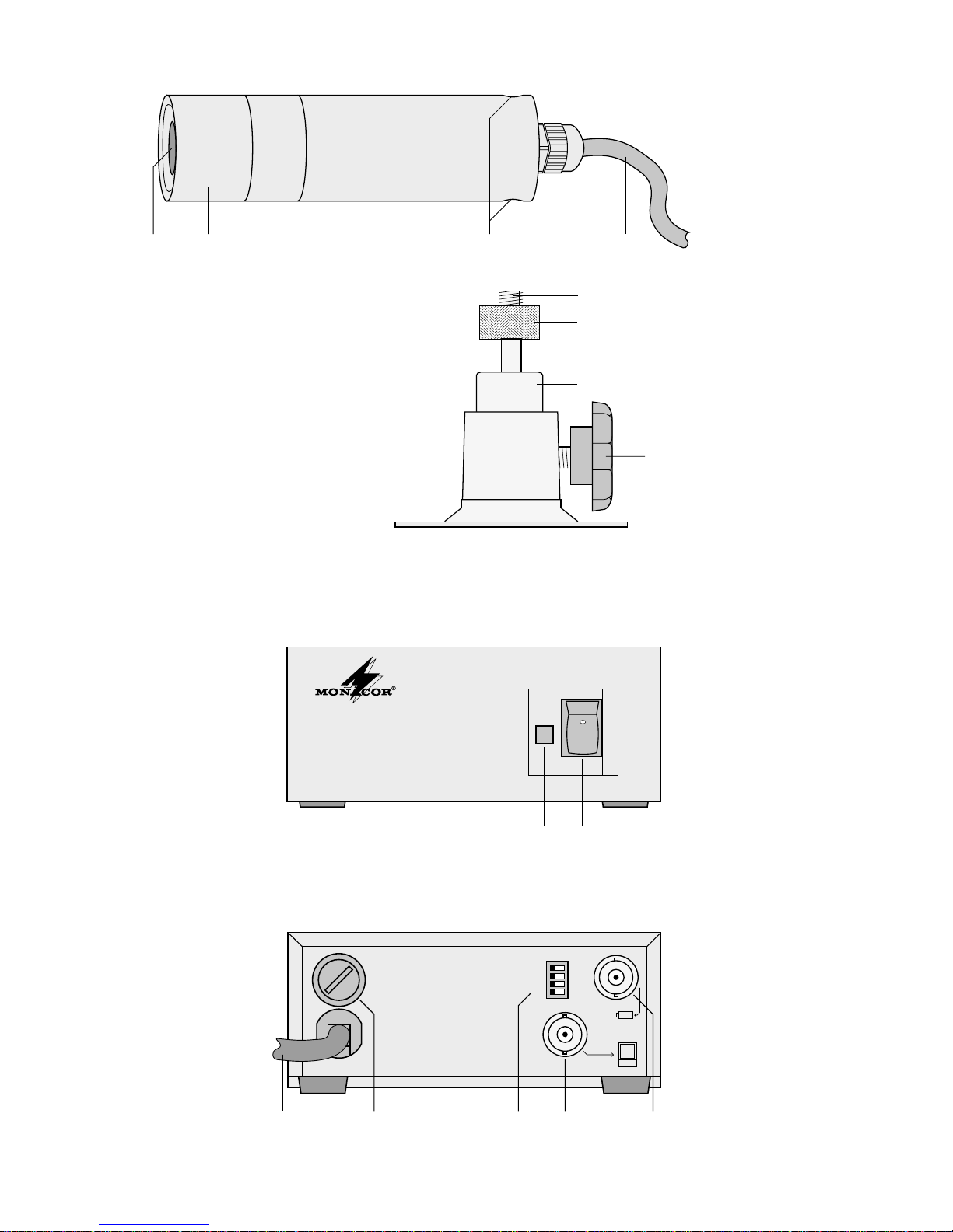
1 Übersicht der Anschlüsse und Bedien-
elemente
1.1 Kamera
1 Objektiv
2 Schraubtülle
3 Gewindebuchsen (6,3mm/
1
/4") zur Montage der
Halterung
4 Anschlusskabel zur Stromversorgungseinheit
1.2 Halterung
5 Gewindebolzen zur Montage der Kamera
6 Rändelmutter
7 Kugelgelenk
8 Feststellschraube
1.3 Stromversorgungseinheit
9 Betriebsanzeige
10 Ein-/Ausschalter
11 Netzkabel zum Anschluss an 230V~/50Hz
12 Sicherungshalter;
eine durchgebrannte Sicherung nur durch eine
gleichen Typs ersetzen
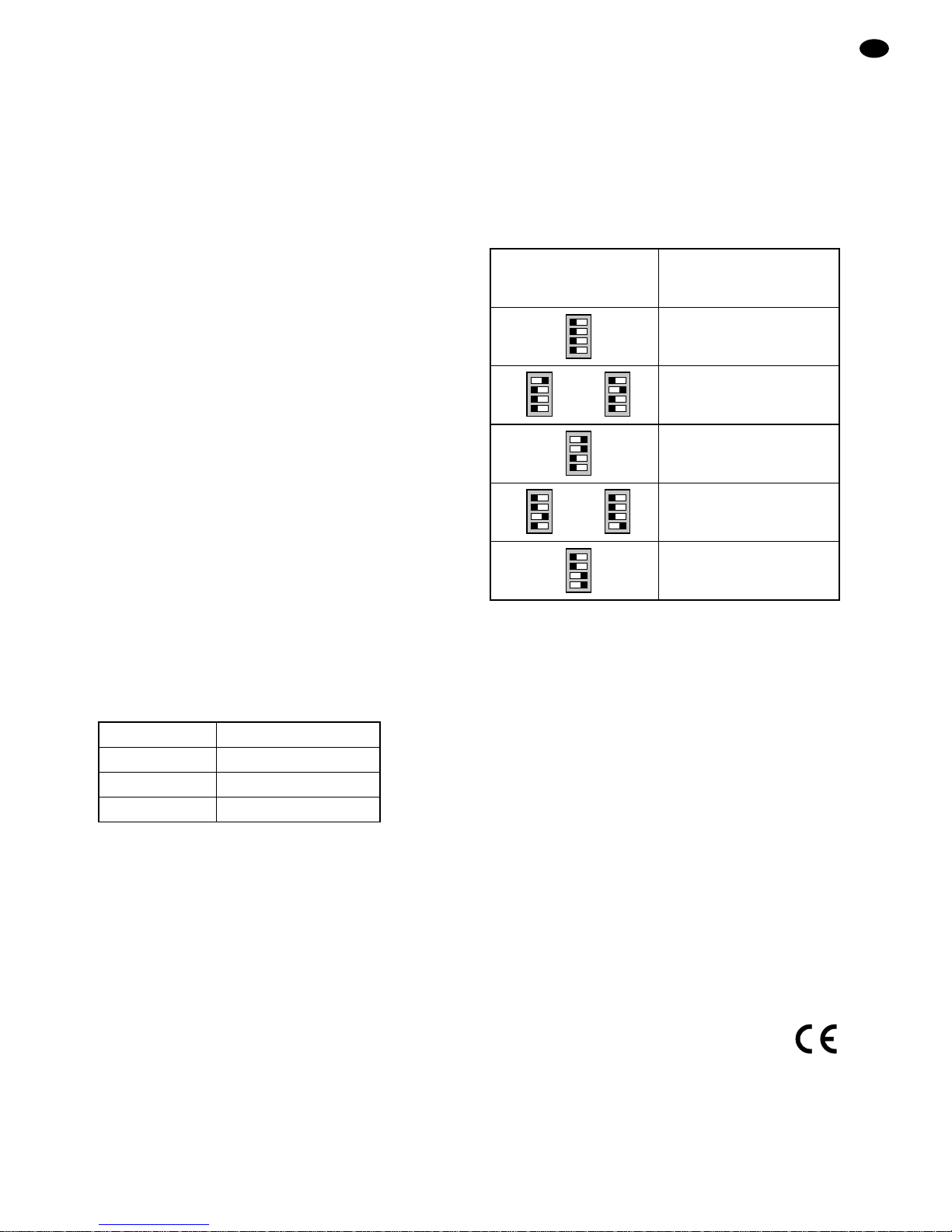
13 vier Schiebeschalter zur Videopegelanpassung
bzw. zur Kompensation von Pegelverlusten bei
Verwendung eines langen Verbindungskabels zur
Kamera;
Einstellung siehe Tabelle auf Seite 5
14 Videoausgang für den Monitoranschluss
15 Anschlussbuchse für die Kamera
(Videoeingang und Kamera-Betriebsspannungsausgang)
2 Hinweise für den sicheren Gebrauch
Die Geräte (Stromversorgungseinheit und Kamera)
entsprechen allen erforderlichen Richtlinien der EU
und sind deshalb mit gekennzeichnet.
Beachten Sie auch unbedingt die folgenden Punkte:
●
Die Stromversorgungseinheit ist nur zur Verwendung im Innenbereich geeignet.
●
Schützen Sie die Geräte vor Hitze (zulässiger Einsatztemperaturbereich
-
10 °C bis +50 °C) und die
Stromversorgungseinheit zusätzlich vor Tropf- und
Spritzwasser und hoher Luftfeuchtigkeit.
●
Stellen Sie keine mit Flüssigkeit gefüllten Gefäße,
z.B. Trinkgläser, auf die Stromversorgungsheit.
●
Das Kameragehäuse ist wasserdicht entsprechend
IP68, d.h. maximale Wassertiefe 1m und maximale
Eintauchdauer 2 Tage.
●
Die in der Stromversorgungseinheit entstehende
Wärme muss durch Luftzirkulation abgegeben werden. Decken Sie darum die Lüftungsschlitze des
Gehäuses nicht ab.
●
Stecken Sie nichts durch die Lüftungsschlitze!
Dabei kann es zu einem elektrischen Schlag kommen.
●
Nehmen Sie die Stromversorgungseinheit nicht in
Betrieb und ziehen Sie sofort den Netzstecker aus
der Steckdose, wenn:
1. sichtbare Schäden an den Geräten oder an der
Netzanschlussleitung vorhanden sind,
2. nach einem Sturz oder ähnlichem der Verdacht
auf einen Defekt besteht,
3. Funktionsstörungen auftreten.
Lassen Sie die Geräte in jedem Fall in einer Fachwerkstatt reparieren.
●
Eine beschädigte Netzanschlussleitung darf nur
durch den Hersteller oder eine Fachwerkstatt ersetzt werden.
●
Ziehen Sie den Netzstecker nie an der Zuleitung aus
der Steckdose, immer am Stecker anfassen!
●
Verwenden Sie für die Reinigung keine scharfen
Reinigungsmittel oder Chemikalien. Benutzen Sie
für die Stromversorgungseinheit nur ein trockenes,
weiches Tuch.
●
Werden die Geräte zweckentfremdet, falsch angeschlossen, nicht richtig bedient oder nicht fachgerecht repariert, kann keine Garantie für sie und
keine Haftung für daraus resultierende Sach- oder
Personenschäden übernommen werden.
3 Einsatzmöglichkeiten
Die Farbkamera und ihre Stromversorgungseinheit
sind speziell für den Einsatz in Video-Überwachungsanlagen konzipiert. Die Kamera besitzt eine automatische Verstärkungsregelung (AGC) und einen automatischen elektronischen Verschluss (
1
/50 –1/100000 s).
Außerdem verfügt sie über eine Gegenlichtkompensation und einen automatischen Weißabgleich (Bereich 2400K bis 11 000K). Durch die Einkabeltechnik
wird zur Verbindung zwischen Kamera und Stromversorgungseinheit nur ein Koaxialkabel benötigt, über
das gemeinsam die Stromversorgung und das Videosignal geführt werden.
Die Kamera ist wetterfest (IP68) und kann auch im
Außenbereich eingesetzt werden. Die Stromversorgungseinheit muss in jedem Fall im Innenbereich betrieben werden.
Sollen die Geräte endgültig aus dem Betrieb
genommen werden, übergeben Sie sie zur
umweltgerechten Entsorgung einem örtlichen
Recyclingbetrieb.
WARNUNG Die Stromversorgungseinheit wird mit le-
bensgefährlicher Netzspannung (230V~)
versorgt. Nehmen Sie daher nie selbst
Eingriffe am Gerät vor. Durch unsachgemäßes Vorgehen besteht die Gefahr
eines elektrischen Schlages.
D
A
CH
4
Page 5
4 Montage
1) Die beiliegende Halterung [oder ggf. eine andere
mit 6,3-mm-Fotogewinde (
1
/4")] an gewünschter
Stelle montieren.
2) Die Feststellschraube (8) der Halterung lösen,
sodass der Gewindebolzen (5) frei beweglich ist
und sich mit Hilfe der Rändelmutter (6) in eine der
beiden Gewindebuchsen (3) der Kamera einschrauben lässt. Falls nach der Inbetriebnahme der
Kamera die Bildwiedergabe auf dem Kopf steht,
muss die andere Gewindebuchse verwendet werden. Durch die zylindrische Form der Kamera ist
vorher nicht zu erkennen, wie herum die Kamera
montiert werden muss.
3) Die Kamera grob ausrichten und durch Festziehen
der Feststellschraube (8) festsetzen. Die genaue
Ausrichtung kann erst nach der Inbetriebnahme
erfolgen.
5 Inbetriebnahme
1) Das Anschlusskabel (4) der Kamera mit der
Buchse TO CAMERA (15) der Stromversorgungseinheit verbinden. Die Länge des Kabels beträgt
30m. Es kann bei Verwendung eines hochwertigen
Kabels bis 500m verlängert werden:
Bis 350m ist auch das Kabel VCC-59 von
MONACOR geeignet.
2) Den Videoausgang VIDEO OUT TO MONITOR
(14) der Stromversorgungseinheit über ein 75-Ω-
Koaxialkabel mit der Video-Eingangsbuchse des
Monitors oder eines Kamera-Umschalters bzw.
Video-Splitters verbinden. Dabei auf korrekten
75-Ω-Abschluss achten.
3) Den Netzstecker in eine Steckdose (230V~/50 Hz)
stecken und mit dem Schalter POWER (10) die
Stromversorgungseinheit einschalten. Die Betriebsanzeige (9) leuchtet.
4) Den angeschlossenen Monitor ebenfalls einschalten und die Kamera genau auf den Überwachungsbereich ausrichten. Steht die Bildwiedergabe auf
dem Kopf, die Kamera um 180° gedreht montieren.
5) Die Schraubtülle (2) der Kamera abschrauben und
das Bild durch Drehen des Objektivs (1) scharf stellen. Die Schraubtülle wieder festschrauben.
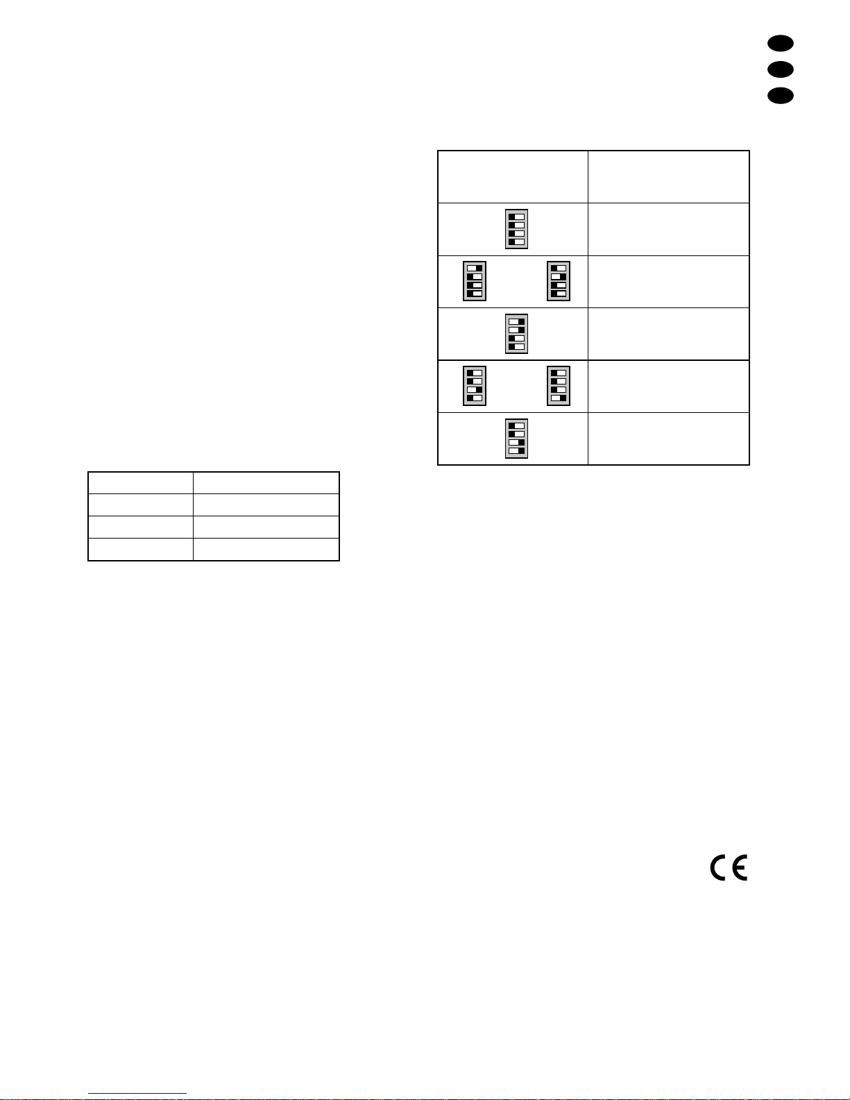
6) Mit den vier Schiebeschaltern VIDEO GAIN ADJ.
(13) auf der Rückseite der Stromversorgungseinheit lässt sich bei Bedarf der Videoausgangspegel
verändern (siehe folgende Tabelle). Damit können
Pegelverluste durch ein langes Verbindungskabel
zwischen der Kamera und der Versorgungseinheit
kompensiert werden.
6 Technische Daten
Bildabtaster: . . . . . . . . . . . 8,5-mm-CCD-Chip (1/3
")
Farbsystem: . . . . . . . . . . . PAL
Synchronisation: . . . . . . . hor.15625 Hz, vert.50Hz
Anzahl der Bildpunkte: . . . hor. 500 x vert. 582
Auflösung: . . . . . . . . . . . . 480Linien
Objektiv: . . . . . . . . . . . . . . 1:2,0/3,6 mm
Mindestbeleuchtung: . . . . 0,05Lux
Signal/Rauschabstand: . . > 50dB
Videoausgang: . . . . . . . . . 1Vss/75 Ω
Schutzart: . . . . . . . . . . . . IP 68
Einsatztemperatur: . . . . .
-
10°C bis +50°C
Stromversorgung: . . . . . . 230V~/50Hz/5 VA
Abmessungen/Gewicht
Kamera: . . . . . . . . . . . . Ø 32mm x 130 mm/200g
Stromversorgungs-
einheit: . . . . . . . . . . . . . 106 x 44 x 96mm/600 g
Änderungen vorbehalten.
D
A
CH
5
Kabeltyp max. Kabellänge
RG-58U 200m
RG-59U 350m
RG-6U 500m
Schalterstellung
VIDEO GAIN ADJ.
Ausgangspegel
ohne Kabelverluste
OFF
OFF
OFF
OFF
+
+
-
-
1,2Vss
oder
OFF
OFF
OFF
OFF
+
+
-
-
OFF
OFF
OFF
OFF
+
+
-
-
1,3Vss
OFF
OFF
OFF
OFF
+
+
-
-
1,4Vss
oder
OFF
OFF
OFF
OFF
+
+
-
-
OFF
OFF
OFF
OFF
+
+
-
-
1,1Vss
OFF
OFF
OFF
OFF
+
+
-
-
1,0Vss
Diese Bedienungsanleitung ist urheberrechtlich für MONACOR®INTERNA TIONALGmbH & Co. KG geschützt.
Eine Reproduktion für eigene kommerzielle Zwecke – auch auszugsweise – ist untersagt.
Page 6
GB
6
Please unfold page 3. Then you can always see the
operating elements and connections described.
1 Connections and Operating Elements
1.1 Camera
1 Lens
2 Screw sleeve
3 Thread jacks (6.3mm/
1
/4") to mount the bracket
4 Connection cable to the power supply unit
1.2 Bracket
5 Thread bolt to mount the camera
6 Knurled nut
7 Ball joint
8 Setscrew
1.3 Power supply unit
9 POWER LED
10 POWER switch
11 Mains cable for the connection to 230V~/50 Hz
12 Fuse holder; only replace a blown fuse by one of
the same type
13 Four sliding switches for video level matching or
compensation of level losses when using a long
connection cable to the camera;
adjustment see table on page 7
14 Video output for the monitor connection
15 Jack to connect the camera
(video input and operating voltage output for the
camera)
2 Safety Notes
The units (power supply unit and camera) correspond
to all required directives of the EU and are therefore
marked with .
Observe in any case the following items:
●
The power supply unit is suitable for indoor use only .
●
Protect the units against heat (admissible ambient
temperature range
-
10°C to +50°C) and the power
supply unit additionally against dripping water,
splash water, and high air humidity.
●
Do not place any vessels filled with liquid, e.g. drinking glasses, on the power supply unit.
●
The camera housing is watertight according to IP68,
i.e. maximum water depth 1m and maximum time of
immersion 2 days.
●
The heat being generated in the power supply unit
has to dissipate via air circulation. Therefore the
vents of the housing must not be covered.
●
Do not insert anything into the vents! This could
result in electric shock.
●
Do not set the power supply unit into operation, and
immediately disconnect the mains plug from the
mains socket if:
1. there is visible damage to the units or to the mains
cable,
2. a defect might have occurred after a drop or similar accident,
3. there are malfunctions.
The units must in any case be repaired by skilled
personnel.
●
A damaged mains cable must only be replaced by
the manufacturer or skilled personnel.
●
Never pull the mains cable to disconnect the mains
plug from the mains socket, always seize the plug.
●
For cleaning do not use any strong detergents or
chemicals. For the power supply unit only use a dry ,
soft cloth.
●
No guarantee claims for the units or liability for any
resulting personal damage or material damage will
be accepted if the power supply unit or the camera
is used for other purposes than originally intended, if
it is not correctly connected, operated, or not repaired in an expert way.
●
Important for U.K. Customers!
The wires in this mains lead are coloured in accordance with the following code:
green/yellow = earth
blue = neutral
brown = live
As the colours of the wires in the mains lead of this
appliance may not correspond with the coloured
markings identifying the terminals in your plug, proceed as follows:
1. The wire which is coloured green and yellow must
be connected to the terminal in the plug which is
marked with the letter E or by the earth symbol
or coloured green or green and yellow.
2. The wire which is coloured blue must be connected to the terminal which is marked with the
letter N or coloured black.
3. The wire which is coloured brown must be connected to the terminal which is marked with the
letter L or coloured red.
Warning – This appliance must be earthed!
If the units are to be put out of operation definitively, take them to a local recycling plant
for a disposal which is not harmful to the environment.
WARNING The power supply unit is supplied with
hazardous mains voltage (230V~).
Leave servicing to skilled personnel
only. Inexpert handling may cause an
electric shock hazard.
Page 7
3 Applications
The colour camera and the power supply unit have
especially been designed for the use in video monitoring systems. The camera has an automatic gain control (AGC) as well as an automatic electronic shutter
(
1
/50 –1/100000 s). Furthermore, it is equipped with a
backlight compensation and an automatic white balance (range 2400K up to 11 000K). Due to the onecable technique, to connect camera and power supply
unit only one coaxial cable is necessary by which the
power supply and the video signal are transferred in
common.
The camera is weatherproof (IP 68) and can also
be used for outside applications. The power supply
unit must in any case be used indoors.
4 Mounting
1) Mount the supplied bracket [or, if desired, another
bracket with 6.3mm (
1
/4") thread] at the desired
place.
2) Loosen the setscrew (8) of the bracket so that the
thread bolt (5) can freely be moved and screwed
into one of the two thread jacks (3) of the camera by
means of the knurled nut (6). If the picture repro-
duction is inverted after setting the camera into op-
eration, the other thread jack must be used. Due to
the cylindrical form of the camera it is not possible
to see before which way round the camera has to
be mounted.
5 Setting into operation
1) Connect the cable (4) of the camera to jack TO
CAMERA (15) of the power supply unit. The length
of the cable is 30m. It can be extended up to 500m
by using a high-quality cable:
Up to 350 m the cable VCC-59 by MONACOR is
suitable as well.
2) Connect the video output VIDEO OUT TO MONI-
TOR (14) of the power supply unit via a 75Ω
coaxial cable to the video input jack of the monitor
or a camera switcher resp. video splitter. Observe
the correct 75Ω termination.
3) Plug the mains plug into a mains socket (230V~ /
50Hz) and switch on the power supply unit with the
POWER switch (10). The POWER LED (9) lights.
4) Switch on the connected monitor as well and align
the camera exactly to the monitoring range. If the
picture reproduction is inverted, mount the camera
by turning it 180°.
5) Screw off the screw sleeve (2) of the camera, and
adjust a clear picture by turning the lens (1). Tighten the screw sleeve again.
6) With the four sliding switches VIDEO GAIN ADJ. (13)
on the rear side of the power supply unit it is possible
to change the video output level, if required (see the
following table). Thus, level losses due to a long
connection cable between the camera and the supply unit can be compensated.
6 Specifications
Image sensor: . . . . . . . . . 8.5 mm (1/3
") CCD chip
Colour system: . . . . . . . . . PAL
Synchronization: . . . . . . . hor. 15625Hz, vert. 50 Hz
Number of pixels: . . . . . . . hor. 500 x vert. 582
Resolution: . . . . . . . . . . . . 480lines
Lens: . . . . . . . . . . . . . . . . 1: 2.0/3.6mm
Minimum illumination: . . . 0.05lux
S/N ratio: . . . . . . . . . . . . . > 50dB
Video output: . . . . . . . . . . 1Vpp/75 Ω
Protective class: . . . . . . . IP68
Ambient temperature: . . .
-
10°C to +50°C
Power supply: . . . . . . . . . 230V~/50Hz/5 VA
Dimensions/weight
camera: . . . . . . . . . . . . dia. 32mm x 130 mm/
200g
power supply unit: . . . . 106 x 44 x 96 mm, 600g
Subject to change.
GB
7
Cable Type Max. Cable Length
RG-58U 200m
RG-59U 350m
RG-6U 500m
Switch position
VIDEO GAIN ADJ.
Output level
without cable losses
OFF
OFF
OFF
OFF
+
+
-
-
1.2Vpp
or
OFF
OFF
OFF
OFF
+
+
-
-
OFF
OFF
OFF
OFF
+
+
-
-
1.3Vpp
OFF
OFF
OFF
OFF
+
+
-
-
1.4Vpp
or
OFF
OFF
OFF
OFF
+
+
-
-
OFF
OFF
OFF
OFF
+
+
-
-
1.1Vpp
OFF
OFF
OFF
OFF
+
+
-
-
1.0Vpp
All rights reserved by MONACOR®INTERNATIONAL GmbH & Co. KG. No part of this instruction manual may
be reproduced in any form or by any means for any commercial use.
Page 8

Ouvrez le présent livret page 3 de manière à visualiser les éléments et branchements.
1 Eléments et branchements
1.1 Caméra
1 Objectif
2 Etui filetage
3 Trous filetés 6,3mm (
1
/4") pour monter le support
4 Câble de branchement pour l’unité d’alimentation
1.2 Support
5 Filetage 6,3mm (1/4") pour monter la caméra
6 Ecrou moleté
7 Rotule d’orientation
8 Vis de fixation
1.3 Unité d’alimentation
9 Diode témoin de fonctionnement
10 Interrupteur Marche/Arrêt
11 Cordon secteur 230V~/50 Hz
12 Porte-fusible : tout fusible fondu ne doit être rem-
placé que par un fusible de même type
13 Quatre interrupteurs à glissières pour adapter le
niveau vidéo ou pour compenser les pertes de
niveau lorsqu’on utilise un câble de liaison de
grande longueur vers la caméra ;
réglage voir tableau page 9.
14 Sortie vidéo pour le branchement du moniteur
15 Prise de connexion pour la caméra
(entrée vidéo et sortie tension de fonctionnement
de la caméra)
2 Conseils d’utilisation et de securité
Les appareils (unité d’alimentation et caméra) répondent à toutes les directives nécessaires de l’Union
Européenne et portent donc le symbole .
Respectez scrupuleusement les points suivants :
●
L’unité d’alimentation n’est conçue que pour une utilisation en intérieur.
●
Protégez les deux appareils de la chaleur (température d’utilisation autorisée
-
10°C à +50°C) et l’unité
d’alimentation supplémentairement de tout type de
projections d’eau, des éclaboussures et d’une humidité élevée.
●
En aucun cas, vous ne devez poser d’objet contenant du liquide ou un verre sur le bloc alimentation.
●
Le boîtier de la caméra est étanche selon les normes IP 68, c’est-à-dire profondeur d’eau maximale
1m et durée maximale d’immersion 2 jours.
●
La chaleur dégagée par l’unité d’alimentation doit
être évacuée par une circulation d’air suffisante :
aucun objet ne doit couvrir les ouïes d’aération.
●
N’introduisez rien dans les ouïes de ventilation,
vous pourriez vous électrocuter.
●
Ne faites pas fonctionner l’unité d’alimentation et débranchez-la immédiatement lorsque :
1. des dommages apparaissent sur les appareils ou
sur le cordon secteur,
2. après une chute..., vous avez un doute sur l’état
des appareils,
3. des dysfonctionnements apparaissent.
Seul un technicien habilité peut effectuer les réparations.
●
Pour nettoyer les appareils, n’utilisez, en aucun cas
de produits chimiques ou d’eau. Utilisez pour l’unité
d’alimentation seulement un chiffon sec et souple.
●
Seul le constructeur ou un technicien habilité peut
remplacer le cordon secteur.
●
Ne le débranchez jamais en tirant directement sur le
cordon secteur.
●
Nous déclinons toute responsabilité en cas de dommages corporels ou matériels résultants d’une utilisation de l’unité d’alimentation ou de la caméra
autre que celle pour laquelle elle a été conçue, si
elle n’est pas correctement branchée, utilisée ou
réparée par un technicien habilité ; en outre, la
garantie deviendrait caduque.
3 Possibilités d’utilisation
Ces deux appareils sont conçus pour une utilisation
dans des centrales de surveillance vidéo. La caméra est
dotée d’un réglage automatique de gain (AGC), d’une
obturation électronique automatique (
1
/50–1/100000 s),
d’une compensation du contre-jour et d’une compensation automatique du blanc (plage 2400K à 11000K). La
technique mono-câble employée permet de n’utiliser
qu’un seul câble coaxial pour la connexion entre la
caméra et l’unité d’alimentation, ce câble transmet en
même temps le signal vidéo et l’alimentation.
La caméra est résistante aux intempéries (IP68) et
peut également être utilisée en extérieur. L’unité d’alimentation n’est conçue que pour une utilisation en
intérieur.
Lorsque les appareils sont définitivement
retirés du service, vous devez les déposer
dans une usine de recyclage à proximité pour
contribuer à leur élimination non polluante.
AVERTISSEMENT L’unité d’alimentation est ali-
mentée par une tension très dangereuse de 230 V~. Ne touchez
jamais l’intérieur de l’appareil car
en cas de mauvaise manipulation, vous pourriez subir une
décharge électrique.
F
B
CH
8
Page 9

4 Montage
1) Montez à l’endroit souhaité le support livré ou le
cas échéant un autre support avec un filetage
6,3mm (
1
/4").
2) Desserrez l’écrou inférieur (8) du support, de telle
sorte que le filetage (5) puisse bouger librement et
s’encastre dans une des deux vis filetées (3) avec
la rondelle (6). Si, après la mise en service de la
caméra, l’image est à l’envers, vous devez utiliser
l’autre vis filetée. La forme cylindrique de la caméra
permet de ne pas identifier son sens de fixation.
3) Dirigez la caméra et fixez-la en tirant la rondelle
inférieure (8). Un alignement précis ne peut être
effectué qu’après la mise en fonction.
5 Mise en fonction
1) Reliez le cordon de la caméra (4) à la prise TO
CAMERA (15) de l’unité d’alimentation ; le câble est
d’une longueur de 30m. Il est possible de le rallonger jusqu’à 500 m en utilisant un câble de grande
qualité.
Pour une distance inférieure à 350 m, il est également possible d’utiliser le câble MONACOR VCC-59.
2) Reliez la sortie vidéo VIDEO OUT TO MONITOR
(14) de l’unité d’alimentation via un câble coaxial
75Ω à l’entrée vidéo du moniteur ou d’un sélecteur
de caméra ou répartiteur vidéo. Attention au branchement 75Ω.
3) Reliez maintenant le cordon secteur à une prise
230 V~/50 Hz, allumez l’unité d’alimentation avec
l’interrupteur POWER (10), la diode, témoin de
fonctionnement (9) s’allume.
4) Allumez ensuite le moniteur relié et dirigez la
caméra vers la zone de surveillance. Montez la
caméra à 180° si l’image est à l’envers.
5) Dévissez l’étui de la caméra (2), réglez la précision
de l’image en tournant l’objectif (1), puis revissez.
6) Avec les 4 interrupteurs VIDEO GAIN ADJ. (13),
situés sur la face arrière du bloc alimentation, il est
possible, si besoin, de modifier le niveau de sortie
vidéo (voir tableau suivant). Il est ainsi possible de
compenser les pertes en ligne générées par le long
câble entre la caméra et le bloc d’alimentation.
6 Caractéristiques techniques
Puce : . . . . . . . . . . . . . . . puce CCD 8,5mm (1/3")
Système couleur : . . . . . . PAL
Synchronisation : . . . . . . . hor. 15625 Hz, vert. 50Hz
Nombre de points : . . . . . hor. 500 x vert. 582
Résolution : . . . . . . . . . . . 480lignes
Objectif : . . . . . . . . . . . . . 1: 2,0/3,6 mm
Luminosité minimale : . . . 0,05 lux
Rapport signal/bruit : . . . . > 50dB
Sortie vidéo : . . . . . . . . . . 1Vcc/75Ω
Protection: . . . . . . . . . . . . IP68
Température ambiante : . .
-
10°C à +50°C
Alimentation . . . . . . . . . . . 230V~/50Hz/5 VA
Dimensions/Poids
Caméra : . . . . . . . . . . . Ø 32 x 130mm/200 g
Unité d’alimentation : . . 106 x 44 x 96mm/600 g
Tout droit de modification réservé.
F
B
CH
9
Type câble Longueur câble max.
RG-58U 200m
RG-59U 350m
RG-6U 500m
Position interrupteurs
VIDEO GAIN ADJ.
Niveau de sortie
sans pertes dues au câble
OFF
OFF
OFF
OFF
+
+
-
-
1,2Vcc
ou
OFF
OFF
OFF
OFF
+
+
-
-
OFF
OFF
OFF
OFF
+
+
-
-
1,3Vcc
OFF
OFF
OFF
OFF
+
+
-
-
1,4Vcc
ou
OFF
OFF
OFF
OFF
+
+
-
-
OFF
OFF
OFF
OFF
+
+
-
-
1,1Vcc
OFF
OFF
OFF
OFF
+
+
-
-
1,0Vcc
Notice d’utilisation protégée par le copyright de MONACOR®INTERNATIONAL GmbH & Co. KG. Toute reproduction même partielle à des fins commerciales est interdite.
Page 10

Vi preghiamo di aprire completamente la pagina 3.
Così vedrete sempre gli elementi di comando e i
collegamenti descritti.
1 Comandi e collegamenti
1.1 Telecamera
1 Obiettivo
2 Boccola a vite
3 Prese filettate 6,3 mm (
1
/4") per il montaggio del
supporto
4 Cavo di collegamento per l’alimentatore
1.2 Supporto
5 Perno filettato 6,3mm (1/4") per il montaggio della
telecamera
6 Dado zigrinato
7 Giunto sferico
8 Vite di bloccaggio
1.3 Alimentatore
9 Spia di funzionamento
10 Interruttore on/off
11 Cavo rete per 230V~/50 Hz
12 Portafusibili; sostituire un fusibile bruciato solo con
uno dello stesso tipo
13 Quattro dip-switch per l’adattamento del livello
video e per la compensazione di perdite del livello
nel caso di un lungo cavo di collegamento per la
telecamera;
per l’impostazione vedi la tabella a pagina 11
14 Uscita video per il collegamento monitor
15 Presa di collegamento per la telecamera
(ingresso video e uscita tensione di alimentazione
della telecamera)
2 Avvertenze di sicurezza
Gli apparecchi (alimentatore e telecamera) sono conformi a tutte le direttive richieste dell’UE e pertanto
portano la sigla .
Durante l’uso si devono osservare assolutamente i
seguenti punti:
●
L’alimentatore è previsto solo per l’uso all’interno di
locali.
●
Proteggere gli apparecchi dal calore (temperatura
d’impiego ammessa
-
10°C a +50°C), e l’alimentatore dall’acqua gocciolante e dagli spruzzi d’acqua e
da alta umidità dell’aria.
●
Non poggiare sullo unità alimentazione contenitori
riempiti di liquidi, p.es. bicchieri.
●
I contenitori delle telecamere sono resistenti all’acqua secondo IP68, cioè la profondità massima di immersione è di 1m e la durata massima è di 2 giorni.
●
Dev’essere garantita la libera circolazione dell’aria
per dissipare il calore che viene prodotto all’interno
dell’alimentatore. Non coprire in nessun modo le
fessure di aerazione.
●
Non inserire oggetti nelle fessure di aerazione. Altrimenti si potrebbe provocare una scarica elettrica.
●
Non mettere in funzione l’alimentatore e staccare
subito la spina rete se:
1 l’alimentatore, la telecamera o il cavo rete presen-
tano dei danni visibili;
2. dopo una caduta o dopo eventi simili sussiste il
sospetto di un difetto;
3. l’apparecchio non funziona correttamente.
Per la riparazione rivolgersi sempre ad una officina
competente.
●
Il cavo rete, se danneggiato, deve essere sostituito
solo dal costruttore o da un laboratorio autorizzato.
●
Staccare il cavo rete afferrando la spina, senza tirare il cavo.
●
Non impiegare in nessun caso detergenti aggressivi
o prodotti chimici per la pulizia; per l’alimentatore
usare solo un panno morbido ed asciutto.
●
Nel caso d’uso improprio, di collegamenti sbagliati,
di impiego scorretto o di riparazione non a regola
d’arte dell’alimentatore o della telecamera, non si
assume nessuna responsabilità per eventuali danni
conseguenti a persone o a cose e cessa ogni diritto
di garanzia.
3 Possibilità d’impiego
Gli apparecchi sono stati realizzati in particolar modo
per l’impiego in impianti di sorveglianza. La telecamera è equipaggiata con regolazione automatica dell’amplificazione (AGC), con un otturatore elettronico automatico (
1
/50 –1/100000 s), con compensazione della
controluce e con compensazione automatica del bianco (da 2400 K fino a 11000 K). Grazie alla tecnica
monocavo, per il collegamento fra la telecamera e l’alimentatore è richiesto solo un cavo coassiale che trasporta l’alimentazione e il segnale video in comune.
La telecamera resiste alle intemperie (IP68) e può
essere utilizzata anche all’esterno. L’alimentatore comunque deve essere sistemato in un ambiente
interno.
Se si desidera eliminare gli apparecchi definitivamente, consegnarli per lo smaltimento ad
un’istituzione locale per il riciclaggio.
AVVERTIMENTO L’alimentatore funziona con ten-
sione di rete di 230V~. Non intervenire mai al suo interno; la manipolazione scorretta può provocare
delle scariche pericolose.
I
10
Page 11

4 Montaggio
1) Montare il supporto in dotazione al punto desiderato. È possibile utilizzare anche un altro supporto
purché dotato di filettatura 6,3mm (
1
/4") per appa-
recchi fotografici.
2) Allentare la vite di bloccaggio (8) del supporto in
modo da poter muovere liberamente il perno filettato (5) che va avvitato ad una delle due prese filettate (3) della telecamera. Stringerlo servendosi del
dado zigrinato (6). Se dopo la messa in funzione,
l’immagine risulta rovesciata, usare l’altra presa
filettata. Data la forma cilindrica della telecamera
non si riesce a vedere il senso di montaggio.
3) Orientare la telecamera in maniera approssimativa
e bloccarla stringendo bene la vite di bloccaggio
(8). L’orientamento esatto è possibile solo dopo la
messa in funzione.
5 Messa in funzione
1) Collegare il cavo di collegamento (4) della telecamera con la presa TO CAMERA (15) dell’alimentatore. Il cavo è lungo 30 metri. Utilizzando cavi di
qualità, si può arrivare fino a 500metri:
Fino a 350m è adatto anche il cavo VCC-59 della
MONACOR.
2) Collegare l’uscita VIDEO OUT TO MONITOR (14)
dell’alimentatore con la presa d’ingresso video del
monitor, di un selettore delle telecamere o di un
video splitter, utilizzando un cavo coassiale 75 Ω.
Fare attenzione alla corretta terminazione 75Ω.
3) Collegare il cavo rete con la rete (230V~/50 Hz) ed
accendere l’alimentatore con l’interruttore POWER
(10). Si accende la spia di funzionamento (9).
4) Accendere il monitor collegato e orientare la telecamera sulla zona da sorvegliare. Se l’immagine risulta rovesciata, montare la telecamera girata di
180°.
5) Svitare la boccola a vite (2) della telecamera e mettere l’immagine a fuoco girando l’obiettivo (1).
Quindi stringere bene la boccola a vite.
6) Se necessario, con i quattro dip-switch VIDEO
GAIN ADJ. (13) posti sul retro dell’unità di alimentazione è possibile modificare il livello video d’uscita (vedi la seguente tabella). In questo modo si possono compensare le perdite di livello dovute ad un
cavo molto lungo fra la telecamera e l’unità di alimentazione.
6 Dati tecnici
Sensore ottico: . . . . . . . . . chip CCD 8,5mm (1/3")
Sistema colore: . . . . . . . . PAL
Sincronizzazione: . . . . . . 15625Hz orizz.,
50Hz vert.
Numero pixel: . . . . . . . . . 500 orizz. x 582 vert.
Risoluzione: . . . . . . . . . . . 480righe
Obiettivo: . . . . . . . . . . . . . 1: 2,0/3,6 mm
Luminosità minima: . . . . . 0,05lux
Rapporto S/R: . . . . . . . . . > 50dB
Uscita video: . . . . . . . . . . 1Vpp/75Ω
Classe di protezione: . . . . IP68
Temperatura d’esercizio: .
-
10°C a +50°C
Alimentazione: . . . . . . . . . 230V~/50Hz/5VA
Dimensioni/Peso
Telecamera: . . . . . . . . . Ø 32mm x 130mm/200 g
Alimentatore: . . . . . . . . 106 x 44 x 96mm/600g
Con riserva di modifiche tecniche.
I
11
Tipo di cavo Lunghezza max. del cavo
RG-58U 200m
RG-59U 350m
RG-6U 500m
Posizione dip-switch
VIDEO GAIN ADJ.
Livello d’uscita
senza perdite per il cavo
OFF
OFF
OFF
OFF
+
+
-
-
1,2Vpp
o
OFF
OFF
OFF
OFF
+
+
-
-
OFF
OFF
OFF
OFF
+
+
-
-
1,3Vpp
OFF
OFF
OFF
OFF
+
+
-
-
1,4Vpp
o
OFF
OFF
OFF
OFF
+
+
-
-
OFF
OFF
OFF
OFF
+
+
-
-
1,1Vpp
OFF
OFF
OFF
OFF
+
+
-
-
1,0Vpp
La MONACOR®INTERNA TIONALGmbH & Co. KG si riserva ogni diritto di elaborazione in qualsiasi forma delle
presenti istruzioni per l’uso. La riproduzione–anche parziale –per propri scopi commerciali è vietata.
Page 12

Vouw bladzijde 3 helemaal open, zodat u steeds
een overzicht hebt van de beschreven bedieningselementen en aansluitingen
1 Bedieningselementen en aansluitingen
1.1 Camera
1 Lens
2 Draadbus
3 6Schroefdraadmoffen (6,3mm/
1
/4") voor montage
van de camerahouder
4 Aansluitingskabel naar voedingseenheid
1.2 Houder
5 Schroefdraadbout voor montage van de camera
6 Kartelmoer
7 Kogelgewricht
8 Stelschroef
1.3 Voedingseenheid
9 POWER-LED
10 POWER-schakelaar
11 Netsnoer voor aansluiting op 230V~/50 Hz
12 Zekeringhouder;
vervang een gesmolten zekering uitsluitend door
een zekering van hetzelfde type
13 vier schuifregelaars voor videoniveauregeling
resp. voor de compensatie van niveauverliezen bij
gebruik van een lange verbindingskabel naar de
camera;
Instelling zie tabel op pagina 13
14 Video-uitgang voor aansluiting van de monitor
15 Jack voor aansluiting van de camera
(video-ingang en camera-uitgang voor de voedingsspanning)
2 Veiligheidsvoorschriften
De apparaten (voedingseenheid en camera) zijn allemaal in overeenstemming met de EU-Richtlijnen en
dragen daarom het -kenmerk.
Let bij ingebruikname in elk geval op het volgende:
●
De voedingseenheid is enkel geschikt voor gebruik
binnenshuis.
●
Vermijd warme en vochtige ruimten (toegelaten omgevingstemperatuurbereik
-
10°C tot +50°C) en be-
scherm de voedingseenheid bovendien tegen druipen spatwater en hoge vochtigheid.
●
Plaats geen met vloeistof gevulde voorwerpen zoals
drinkglazen, etc. op het apparaat.
●
De camerabehuizing is waterdicht conform IP 68,
d.w.z. maximale waterdiepte van 1 m en maximale
onderdompeltijd van 2 dagen.
●
De warmte die in de voedingseenheid ontstaat,
moet door ventilatie worden afgevoerd. Zorg er daarom voor, dat de ventilatieopeningen aan de zijkanten van de behuizing door geen enkel voorwerp worden afgedekt.
●
Zorg ervoor dat u niets in de ventilatieopeningen
steekt of laat vallen. Er bestaat immers gevaar voor
elektrische schokken.
●
Schakel het toestel niet in en trek onmiddellijk de
stekker uit het stopcontact wanneer:
1. het toestel of het netsnoer zichtbaar beschadigd
is,
2. er een defect zou kunnen optreden nadat het
toestel bijvoorbeeld gevallen is,
3. het toestel slecht functioneert.
Het toestel moet in elk geval hersteld worden door
een gekwalificeerd vakman.
●
Een beschadigd netsnoer mag enkel door de fabrikant of door een gekwalificeerd persoon hersteld
worden.
●
Trek de stekker nooit met het snoer uit het stopcontact.
●
Gebruik voor de reiniging geen agressieve detergenten of chemicaliën. Gebruik voor de reiniging
van de voedingseenheid uitsluitend een droge,
zachte doek.
●
In geval van ongeoorloofd of verkeerd gebruik, verkeerde aansluiting, foutieve bediening of van herstelling door een niet-gekwalificeerd persoon vervalt
de garantie en de verantwoordelijkheid voor hieruit
resulterende materiële of lichamelijke schade.
3 Toepassingen
De toestellen zijn speciaal ontworpen voor gebruik in
video-bewakingsinstallaties. De camera is uitgerust
met een automatische versterkingsregeling (AGC), een
automatische elektronische sluiter (
1
/50 –1/100000 s),
een tegenlichtcompensatie en een automatische witbalans (bereik 2400 K tot 11 000 K). Dankzij de eenkabeltechniek is voor de verbinding tussen camera en
voedingseenheid enkel een coaxiale kabel vereist. Via
deze kabel wordt de voedingsspanning en het videosignaal geleverd.
De camera is weerbestendig (IP 68) en kan ook
buiten gebruikt worden. De voedingseenheid mag
enkel binnen gebruikt worden.
Wanneer de toestellen definitief uit bedrijf genomen worden, bezorg ze dan voor milieuvriendelijke verwerking aan een plaatselijk
recyclagebedrijf.
WAARSCHUWING De netspanning (230V~) waar-
mee de voedingseenheid gevoed
wordt is levensgevaarlijk! Open
de eenheid niet, want door
onzorgvuldige ingrepen loopt u
het risico van een elektrische
schok.
NL
B
12
Page 13

4 Montage
1) Monteer de meegeleverde houder [of eventueel
een andere houder met 6,3mm-schroefdraad (
1
/4")]
op de gewenste plaats.
2) Draai de stelschroef (8) van de houder los, zodat de
schroefdraadbout (5) vrij kan bewegen en met behulp van de kartelmoer (6) in een van beide schroefdraadmoffen (3) van de camera ingeschroefd kan
worden. In het geval dat na de ingebruikname van
de camera de beeldweergave onderste boven
staat, dient de andere schroefdraadmof gebruikt te
worden. Door de cylindrische vorm van de camera
kan op voorhand niet bepaald worden, hoe de
camera gemonteerd moet worden.
3) Plaats de camera ongeveer in de juiste richting en
zet hem vast door de stelschroef (8) vast aan te
draaien. Een precieze uitlijning kan pas na de ingebruikname gebeuren.
5 Ingebruikname
1) Verbind de aansluitingskabel (4) van de camera
met de jack TO CAMERA (15) van de voedingseenheid. De lengte van de kabel bedraagt 30m en
kan door gebruik van een hoogwaardige kabel tot
500m verlengd worden.
Tot een kabellengte van 350m kunt u ook de kabel
VCC-59 van MONACOR gebruiken.
2) Verbind de video-uitgang VIDEO OUT TO MONITOR (14) van de voedingseenheid via een 75 Ω-
coaxkabel met de video-ingangsjack van de monitor of van een camera-omschakelaar resp. videosplitter. Zorg hierbij voor een correcte 75Ω-af-
sluiting.
3) Plug de netstekker in een stopcontact (230V~/
50Hz), en schakel met de POWER-schakelaar (10)
de voedingseenheid in. De POWER-LED (9) licht
op.
4) Schakel de aangesloten monitor eveneens in, en
richt de camera precies op het te bewaken bereik.
Staat de beeldweergave onderste boven, draai de
camera dan 180° om alvorens te monteren.
5) Schroef de draadbus (2) van de camera los, en
draai aan de lens (1) tot het beeld scherp is.
Schroef de draadbus weer vast.
6) Met de vier schuifregelaars VIDEO GAIN ADJ. (13)
aan de achterzijde van de voedingseenheid kan u
het video-uitgangsniveau eventueel wijzigen (zie
volgende tabel). Zo kan u niveauverliezen door een
lange verbindingskabel tussen camera en voedingseenheid compenseren.
6 Technische gegevens
Beeldsensor: . . . . . . . . . . 8,5-mm-CCD-Chip (1/3")
Kleurensysteem: . . . . . . . PAL
Synchronisatie: . . . . . . . . hor. 15625Hz, vert. 50 Hz
Aantal pixels: . . . . . . . . . . hor. 500 x vert. 582
Resolutie: . . . . . . . . . . . . . 480lijnen
Lens: . . . . . . . . . . . . . . . . 1 : 2,0/3,6mm
Minimale belichting: . . . . . 0,05Lux
Signaal/Ruis-verhouding: > 50dB
Video-uitgang: . . . . . . . . . 1Vss/75 Ω
Beschermingsklasse: . . . . IP68
Omgevingstemperatuur: .
-
10°C tot +50°C
Voedingsspanning: . . . . . 230V~/50Hz/5 VA
Afmetingen/Gewicht
camera: . . . . . . . . . . . . Ø 32mm x 130 mm/200g
voedingseenheid: . . . . 106 x 44 x 96mm/600g
Wijzigingen voorbehouden.
NL
B
13
Kabeltype max. Kabellengte
RG-58U 200m
RG-59U 350m
RG-6U 500m
Schakelaarinstelling
VIDEO GAIN ADJ.
Uitgangsniveau
zonder kabelverliezen
OFF
OFF
OFF
OFF
+
+
-
-
1,2Vss
of
OFF
OFF
OFF
OFF
+
+
-
-
OFF
OFF
OFF
OFF
+
+
-
-
1,3Vss
OFF
OFF
OFF
OFF
+
+
-
-
1,4Vss
of
OFF
OFF
OFF
OFF
+
+
-
-
OFF
OFF
OFF
OFF
+
+
-
-
1,1Vss
OFF
OFF
OFF
OFF
+
+
-
-
1,0Vss
Deze gebruiksaanwijzing is auteursrechterlijk beschermd voor MONACOR®INTERNA TIONALGmbH & Co. KG.
Reproductie voor eigen commerciële doeleinden – ook bij wijze van uitzondering – is niet toegestaan.
Page 14

Por favor abrir el manual en la página 3 para visualizar todos los elementos operativos y conexiones.
1 Conexiones y elementos operativos
1.1 Cámara
1 Lente
2 Capuchón roscado
3 Roscas 6,3mm (
1
/4") para montar el soporte
4 Cable de conexión a la unidad de alimentación
1.2 Suporte
5 Perno roscado para montar la cámara
6 Tuerca bordeada
7 Juntura de orientación
8 Tornillo de fijación
1.3 Unidad de alimentación
9 Indicación de funcionamiento
10 Interruptor para conectar/desconectar
11 Cable de conexión a 230V~/50 Hz
12 Porta-fusible; todo fusible fundido debe de ser
cambiado solamente por un fusible de mismo tipo.
13 Cuatro interruptores deslizantes para adaptar el
nivel vídeo o para compensar las perdidas de nivel
cuando se utiliza un cable de conexión de gran longitud hacia la cámara;
para el reglaje ver tabela página 15.
14 Salida vídeo para la conexión del monitor
15 Toma de conexión para la cámara
(entrada video y salida tensión de funcionamiento
de la cámara)
2 Consejos de seguridad
Las unidades (alimentador y cámara) corresponden a
todas las Directivas requeridas por la UE y por ello
están marcadas con .
Respetar los siguientes puntos:
●
El alimentador está concebido solamente para una
utilización en interiores.
●
Proteger aparatos del calor (temperatura permitida
de funcionamiento
-
10°C hasta +50°C) y el alimen-
tador también de todo tipo de proyecciones de
aguas, de las salpicaduras y de la humedad elevada.
●
No poner recipientes llenados de líquido, p.ej. floreros, vasos, etc., sobre el alimentador.
●
La caja de la cámara es estanca según la norma
IP68, es decir, profundidad de agua máxima 1m y
duración máxima de inmersión 2 días.
●
El calor desprendido por el alimentador debe evacuarse por una circulación de aire correcta. No
obstruir nunca las rejillas de ventilación por ningún
objeto.
●
No poner nada dentro las rejillas de ventilación:
podrá electrocutarse.
●
No conectar el alimentador y desconectarlo de inmediato de red ya que:
1. los aparatos o el cable de red presentan desperfectos,
2. después de una caida o accidente parecido el
equipo pueda estar dañado,
3. aparecen disfunciones.
Llamar a un técnico especialista para efectuar las
reparaciones.
●
Solamente el fabricante o un técnico habilitado pueden reemplazar el cable de red dañado.
●
No desconectar el alimentador tirando del cable de
conexión.
●
Para limpiar los aparatos, utilizar en ningún caso
productos químicos o agua. Para el alimentador, utilizar solamente un trapo seco y blando.
●
Declinamos toda responsabilidad en caso de daños
corporales o materiales resultantes si los aparatos
se utilizan con una finalidad diferente a la que le es
propia, si no están conectados o utilizados correctamente, o reparados por una persona habilitada,
además, carecería de todo tipo de garantía.
3 Aplicaciones
Los aparatos se han diseñado sobre todo para el uso
sistemas video de vigilancia. La cámara está equipada
con un control de ganancia automático (AGC), un obturador electrónico automático (
1
/50 –1/100000 s), un balance automático de blanco (rango 2400K a 11000K)
y una compensación contraluz. A causa de la técnica
mono-cable, solamente es necesario para su conexión
un cable coaxial para que la alimentación y la señal
video se transfieran en común.
La cámara es impermeable (IP68) y puede utilizarse para aplicaciones en el exterior. La unidad de alimentación solamente puede utilizarse en el interior.
Cuando los aparatos están definitivamente
retirados del servicio, debe depositarlos en
una fábrica de reciclaje próxima para contribuir a sus eliminaciones no contaminantes.
ADVERTENCIA El alimentador está alimentado por
una tensión muy peligrosa 230V~.
No manipule nunca el interior del
aparato, en caso de manipulación
inadecuada, puede sufrir una descarga eléctrica.
E
14
Page 15

4 Montaje
1) Montar el soporte entregado, [o eventualmente,
otro suporte con una rosca de 6,3mm (
1
/4")] en el
lugar deseado.
2) Soltar el tornillo de fijación (8) del soporte para que
el perno roscado (5) pueda moverse libremente y
pueda atornillarse en una de las roscas (3) de la
cámara mediante la tuerca (6). Si la imagen está
invertido poniendo la cámara en funcionamiento,
debe utilizarse la otra rosca. Debido a la forma
cilíndrica de la cámara no es posible ver antes de
que la cámara esté montada.
3) Instalar la cámara enfocándola adecuadamente y
apretar el tornillo de fijación (8). Para un enfoque
exacto, debe hacerse únicamente después de poner la cámara en funcionamiento.
5 Puesta en funcionamiento
1) Conectar el cable (4) de la cámara en el jack TO
CAMERA(15) de la unidad de alimentación. La longitud del cable es de 30m. Puede extenderse
hasta 500m usando un cable de alta calidad:
Para una distancia inferior a 350m el cable VCC-59
de MONACOR es también conveniente.
2) Conectar la salida video VIDEO OUT TO MONITOR (14) de la unidad de alimentación vía un cable
coaxial 75Ω a la entrada video del monitor o de un
secuenciador de cámara resp. de un video splitter.
Prestar atención a la correcta terminación de 75Ω.
3) Poner el enchufe en la toma de red (230V~/50 Hz)
y conectar la unidad de alimentación mediante el
interruptor POWER (10). El LED (9) se ilumina.
4) Encender el monitor conectado y encuadrar la cámara exactamente al lugar que debe ser visualizado. Si la imagen está invertida, montar la cámara
volviéndola 180°.
5) Desatornillar el capuchón (2) de la cámara, y girar la lente (1) para obtener una imagen nítida.
Atornillar de nuevo el capuchón.
6) Con los 4 interruptores VIDEO GAIN ADJ. (13),
situados en la parte trasera de la unidad de alimentación, es posible, si es necesario, modificar el
nivel de salida vídeo (ver tabela siguiente). Es posible entonces compensar las perdidas en línea
ganadas por un cable largo entre la cámara y el
unidad de alimentación.
6 Características técnicas
Sensor de imagen: . . . . . 8,5mm (1/3") chip CCD
Sistema color: . . . . . . . . . PAL
Sincronización: . . . . . . . . hor. 15625 Hz, vert. 50 Hz
Nombre de pixels: . . . . . . hor. 500 x 582 vert.
Resolución: . . . . . . . . . . . 480 líneas
Lente: . . . . . . . . . . . . . . . . 1 : 2,0/3,6mm
Iluminación mínima: . . . . . 0,05lux
Relación señal/ruido: . . . > 50dB
Salida video: . . . . . . . . . . 1Vcc/75Ω
Protección: . . . . . . . . . . . . IP68
Temperatura ambiente: . .
-
10°C hasta +50°C
Alimentador: . . . . . . . . . . 230V~/50 Hz/5VA
Dimensiones/Peso
Cámara: . . . . . . . . . . . . dia. 32mm x 130 mm/
200g
Unidad de
alimentación: . . . . . . . . 106 x 44 x 96mm/600g
Reservado el derecho a cualquier modificación.
E
15
Tipo del cable Max. longitud del cable
RG-58U 200m
RG-59U 350m
RG-6U 500m
Posición interruptores
VIDEO GAIN ADJ.
Nivel de salida
sin perdidas debidas al cable
OFF
OFF
OFF
OFF
+
+
-
-
1,2Vcc
o
OFF
OFF
OFF
OFF
+
+
-
-
OFF
OFF
OFF
OFF
+
+
-
-
1,3Vcc
OFF
OFF
OFF
OFF
+
+
-
-
1,4Vcc
o
OFF
OFF
OFF
OFF
+
+
-
-
OFF
OFF
OFF
OFF
+
+
-
-
1,1Vcc
OFF
OFF
OFF
OFF
+
+
-
-
1,0Vcc
Manual de instrucciones protegido por el copyright de MONACOR®INTERNATIONAL GmbH & Co. KG.
Toda reproducción mismo parcial con fines comerciales está prohibida.
Page 16

Fold side 3 ud. Så kan De altid se de beskrevne
betjeningselementer og tilslutninger.
1 Betjeningselementer og tilslutninger
1.1 Kamera
1 Objektiv
2 Omløber
3 6,3mm (
1
/4") gevindbøsninger for montering af be-
slag
4 Tilslutningskabel for strømforsyning
1.2 Beslag
5 6,3mm (1/4") gevindbolt for montering af kamera
6 Riflede møtrik
7 Kugleled
8 Stilleskrue
1.3 Strømforsyning
9 Lysdioden POWER
10 Hovedafbryderen POWER
11 Netkabel for tilslutning til 230V~/50 Hz
12 Sikringsholder;
udskift kun en sikring, der er sprunget, med en
sikring af samme type
13 Fire skydeomskiftere for videoinveautilpasning
eller kompensation for signaltab ved brug af langt
kabel op til kameraet;
for indstilling se tabellen på side 17
14 Videoudgang for tilslutning af monitor
15 Bøsning for tilslutning af kamera
(videoindgang og udgang for styrespænding til
kameraet)
2 Vigtige sikkerhedsoplysninger
Enhederne (strømforsyning og kamera) overholder
alle påkrævede EU regulativer og er derfor mærket
med .
Vær altid opmærksom på følgende:
●
Strømforsyningen er kun beregnet til indendørs
brug.
●
Beskyt enhederne mod varme (tilladt temperaturområde under drift
-
10 °C op til +50 °C) og beskyt
desuden strømforsyningen mod vanddråber og
-stænk og høj luftfugtighed.
●
Undgå at placere væskefyldte genstande, strømforsyning som f.eks. glas, ovenpå enheden.
●
Kamerahuset er vandtæt efter IP 68, d.v.s. maksimum vanddybde på 1 m og maksimum indtrængningstid på 2 dage.
●
V armen, der udvikles i strømforsyningen, skal kunne
slippe ud ved hjælp af luftcirkulation. Kabinettets
ventilationshuller må derfor ikke tildækkes.
●
Undlad at indføre eller tabe noget i ventilationshullerne! Dette kan medføre elektrisk stød.
●
Tag ikke strømforsyningen i brug og tag straks
stikket ud af stikkontakten i følgende tilfælde:
1. hvis der er synlig skade på strømforsyningen eller
kameraet
2. hvis der kan være opstået skade, efter at enhederne er tabt eller lignende
3. hvis der forekommer fejlfunktion.
Enhederne skal altid repareres af autoriseret personel.
●
Et beskadiget netkabel må kun repareres af producenten eller af autoriseret personel.
●
Tag aldrig stikket ud af stikkontakten ved at trække i
kablet, tag fat i selve stikket!
●
Til rengøring må under ingen omstændigheder benyttes kraftige opløsninger eller kemikalier. Til rengøring af strømforsyningen må kun benyttes en tør,
blød klud.
●
Hvis enhederne benyttes til andre formål, end de
oprindeligt er beregnet til, hvis de ikke er tilsluttet
korrekt, hvis de betjenes forkert, eller hvis de ikke
repareres af autoriseret personel, omfattes eventuelle skader ikke af garantien.
3 Funktioner
Enhederne er specielt konstrueret til brug i videoovervågningssystemer. Kameraet er ver udstyret med
en automatisk forstærkningsregulering (AGC), en automatisk elektronisk lukker (
1
/50
–
1
/100000
s) og en
automatisk hvidbalance (i området 2400K til
11 000 K), og kameraet kompenserer automatisk for
baggrundslys. Når man skal tilslutte kameraet og
strømforsyningen, har man på grund af 1-kabel teknikken kun brug for ét koaksialkabel til fælles fremføring
af strøm og videosignal.
Kameraet er vejrbestandigt (IP68) og kan således
også bruges til udendørs formål. Strømforsyningen må
under alle omstændigheder kun benyttes indendørs.
Hvis enhederne skal tages ud af drift for
bestandigt, skal de bringes til en lokal genbrugsstation for bortskaffelse.
ADVARSEL Strømforsyningen benytter livsfarlig net-
spænding (230 V~). For at undgå fare
for elektrisk stød, må enheden ikke
åbnes. Overlad servicering til autoriseret personel.
DK
16
Page 17

4 Montering
1) Montér det medfølgende beslag [eller – om ønsket
– et andet beslag med 6,3mm (
1
/4")] gevind på den
ønskede position.
2) Frigør stilleskruen (8) på beslaget, så det bliver muligt frit at flytte gevindbolten (5) og fastskrue den i
en af kameraets to gevindbøsninger (3) ved hjælp
af den riflede møtrik (6). Hvis billedgengivelsen inverteres, når kameraet tages i brug, skal den anden
gevindbøsning benyttes. Det er på grund af kameraets cylindriske form ikke muligt på forhånd at se,
hvilken vej kameraet skal vende.
3) Foretag en omtrentlig indstilling af kameraet og
fastgør det ved at stramme stilleskruen (8). Det er
ikke muligt at foretage en nøjagtig justering, før
kameraet er taget i brug.
5 Ibrugtagning
1) Forbind kameraets kabel (4) med bøsningen
VIDEO IN TO CAMERA (15) på strømforsyningen.
Kablets længde er 30meter. Det kan forlænges op
til 500meter ved hjælp af et kabel af høj kvalitet:
Ved en kabellængde på op til 350 meter er kablet
VCC-59 fra MONACOR også velegnet.
2) Forbind videoudgangen VIDEO OUT TO MONITOR (14) på strømforsyningen med monitorens
videoindgang eller med en kameraomskifter resp.
video-splitter via et 75Ω koaksialkabel. Sørg for
korrekt 75Ω terminering.
3) Sæt stikket i en stikkontakt (230V~/50 Hz) og tænd
for strømforsyningen med hovedafbryderen POWER
(10). Lysdioden POWER (9) lyser.
4) Tænd desuden for den tilsluttede monitor og justér
kameraet, så det præcist indfanger det ønskede
overvågningsområde. Hvis billedgengivelsen er
inverteret, skal kameraet drejes 180° og monteres
igen.
5) Skru kameraets omløber (2) af og justér billedet ved
at dreje på objektivet (1), indtil et klart billede opnås.
Fastgør herefter omløberen igen
6) Med de fire skydeomskiftere VIDEO GAIN ADJ.
(13) på bagsiden af strømforsyningen er det muligt
at ændre videoudgangsniveau, hvis nødvendigt (se
nedenstående tabel). Derved kan der kompenseres
for signaltab som følge af lang kabler mellem kameraet og strømforsyningen.
6 Tekniske specifikationer
Billedsensor: . . . . . . . . . . 8,5mm (1/3
") CCD chip
Farvesystem: . . . . . . . . . . PAL
Synkronisering: . . . . . . . . hor. 15625Hz, vert. 50 Hz
Antal billedelementer: . . . hor. 500 x vert. 582
Opløsning: . . . . . . . . . . . . 480linier
Objektiv: . . . . . . . . . . . . . . 1: 2,0/3,6 mm
Minimumbelysning: . . . . . 0,05 Lux
Signal/støj forhold: . . . . . > 50dB
Videoudgang: . . . . . . . . . . 1Vpp/75 Ω
Beskyttelsesklasse: . . . . . IP68
Omgivelsestemperatur: . .
-
10°C op til +50°C
Strømforsyning: . . . . . . . . 230V~/50 Hz/5VA
Dimensioner/Vægt
kamera: . . . . . . . . . . . . Ø 32mm x 130 mm/200g
strømforsyning: . . . . . . 106 x 44 x 96mm/600 g
Ret til ændringer forbeholdes.
DK
17
Kabeltype Maks. kabellængde
RG-58U 200m
RG-59U 350m
RG-6U 500m
Omskifter stilling
VIDEO GAIN ADJ.
Udgangs niveau
uden kabel tab
OFF
OFF
OFF
OFF
+
+
-
-
1,2Vpp
eller
OFF
OFF
OFF
OFF
+
+
-
-
OFF
OFF
OFF
OFF
+
+
-
-
1,3Vpp
OFF
OFF
OFF
OFF
+
+
-
-
1,4Vpp
eller
OFF
OFF
OFF
OFF
+
+
-
-
OFF
OFF
OFF
OFF
+
+
-
-
1,1Vpp
OFF
OFF
OFF
OFF
+
+
-
-
1,0Vpp
Alle rettigheder til denne brugsvejledning tilhører MONACOR®INTERNATIONAL GmbH & Co. KG. Ingen dele
af denne vejledning må reproduceres under ingen omstændigheder til kommerciel anvendelse.
Page 18

Ha sidan 3 uppslagen för att åskådliggöra hänvisningarna i texten.
1 Funktioner och anslutningar
1.1 Kamera
1 Objektiv
2 Skruvlock
3 Skruvfattningar med 6,3 mm (1/4") skruvgänga för
montering av fästet
4 Kabel för anslutning till strömförsörjningsenheten
1.2 Fäste
5 Bult med 6,3 mm (1/4") skruvgänga för montering
av kameran
6 Fästmutter
7 Kulled
8 Ställskruv
1.3 Strömförsörjningsenhet
9 Diodindikering för ström
10 Strömbrytare
11 Elsladd för anslutning till 230V~/50 Hz
12 Säkringshållare; ersätt endast med säkring av
samma typ.
13 Fyra omställnings knappar för video nivå anpas-
sning eller kompensation av nivå förluster när man
använder en lång kabel till kameran;
för justeringar se tabell på sidan 19.
14 Videoutgång för anslutning till monitor
15 Anslutning för kamera
(videoingång samt arbetsspänning till kamera)
2 Säkerhetsföreskrifter
Enheterna (kamera och nätdel) uppfyller EU direktiven
och är därför märkta med symbolen .
Ge även akt på följande:
●
Nätdelen är endast avsedda för inomhusbruk.
●
Enheterna skall skyddas mot hög värme (arbetstemperatur
-
10 °C till +50 °C). Nätdelen skall skyddas
dessutom mot vätskor och hög luftfuktighed.
●
Placera inte föremål innehållande vätskor, nätdel
t.ex. dricksglass, på enheten.
●
Kamera huset är vattentätt enligt IP 68, det innebär
ett maximum på 1 meter ner i vattnet under max.
2 dagar.
●
Värmen inne i nätdel som alstras vid användning
skall ledas bort genom självcirkulering. Täck därför
aldrig över ventilationshålen.
●
Stoppa eller tappa aldrig något i kylhålen då detta
kan leda till elektrisk shock.
●
Ta ut elsladden ur elurtaget om något av följande fel
uppstår.
1. Elsladden eller enheterna har synliga skador.
2. Enheterna är skadade genom fall ed.
3. Det finns andra felfunktioner.
Enheterna skall alltid lagas på auktoriserad verkstad.
●
En skadad elsladd skall bytas av återförsäljare eller
auktoriserad verkstad.
●
Drag aldrig ut kontakten genom att dra i sladden
utan ta tag i kontaktkroppen.
●
Rengör endast med en ren och torr trasa. Använd
aldrig vätskor i någon form då dessa kan rinna in
och orsaka kortslutning.
●
Om kamera eller nätdelen används för andra
ändamål än avsett, om den kopplas in felaktigt, om
den används på fel sätt eller inte repareras av auktoriserad personal upphör alla garantier att gälla och
inget ansvar tas heller för uppkommen skada på
person eller materiel.
3 Användningsområden
Färgkameran och strömförsörjningsenheten är speciellt framtagen för användning i videoövervakningssystem. Kameran är utrustad med en automatisk
känslighetskontroll (AGC) och automatisk elektronisk
slutare med slutartider (
1
/50 –1/100000 s). Dessutom har
kameran automatisk vitbalans (arbetsområde 2400 K
till 11 000 K) och även kompensering för bakgrundsljus. Tack vare enkabelstekniken behövs endast en
kabel för att ansluta både strömförsörjning och bild.
Kameran är vattentät (IP68) och kan därför användas utomhus. Strömförsörjningen måste dock installeras inomhus.
4 Montering
1) Montera det medföljande fästet [eller eventuell en
annan fäste med 6,3mm skruvgänga (
1
/4")] på öns-
kad position.
2) Lossa ställskruven (8) på fästet så att skruvbulten
(5) kan röras fritt och skruvas in i en av de 2 skruv-
fattningarna (3) på kameran med fästmuttern (6).
Om bilden visas uppochner efter inkoppling skall
den andra fattningen användas. Då kameran är
rund går det inte att avgöra om kameran är monte-
rad uppochner.
3) Vinkla kameran enligt önskemål och fixera den med
ställskruven (8). Exakt inställning av kamerafästet
kan göras endast när kameran är i drift.
Om enheterna skall kasseras bör de lämnas
till återvinning.
VARNING
Strömförsörjningsenheten använder hög
spänning internt (230V~). Öppna därför
aldrig chassiet på egen hand utan överlåt all service till auktoriserad verkstad.
S
18
Page 19

5 Inkoppling
1) Anslut kabeln (4) på kameran till ingången TO
CAMERA (15) på den medföljande strömförsörjningsenheten. Längden på kabeln är 30meter. Den
kan förlängas till 500 m om en högkvalitetskabel
används.
Upp till 350meter kabel MONACOR VCC-59 är
också lämplig.
2) Anslut videoutgången VIDEO OUT TO MONITOR
(14) på strömförsörjningsenheten till videoingången på monitorn eller videoomkopplaren med koaxkabel 75Ω. Se till att 75Ω läget är inställt.
3) Anslut strömförsörjningsenheten till elnätet (230V~/
50Hz) och slå på enheten med strömbrytare
POWER (10). Dioden (9) tänds vid påslag.
4) Slå på den anslutna monitorn och ställ in kamerafästet i förhållande till monitorn. Om bilden är uppochner skall kameran vändas 180°.
5) Lossa skruvlocket (2) och ställ in bilden genom att
vrida objektivet (1). Lås sedan fast skruvlocket
igen.
6) Med de fyra knapparna VIDEO GAIN ADJ. (13) på
framsidan av strömförsörjningen så är det möjligt
att ändra utgångs nivån på video signalen, om
detta krävs (se nedanstående tabell). Det är också
så att nivå förluster pga en lång kabel mellan kameran och strömförsörjningen kan kompenseras.
6 Specifikationer
Bildsensor: . . . . . . . . . . . . 8,5 mm (1/3") CCD chip
Färgsystem: . . . . . . . . . . . PAL
Synkronisering: . . . . . . . . hor. 15625Hz, vert. 50 Hz
Antal pixels: . . . . . . . . . . . hor. 500, vert. 582
Upplösning: . . . . . . . . . . . 480linjer
Objektiv: . . . . . . . . . . . . . . 1: 2,0/3,6 mm
Minimibelysning: . . . . . . . 0,05lux
Störavstånd: . . . . . . . . . . > 50dB
Videoutgång: . . . . . . . . . . 1Vpp/75 Ω
Skyddsklass: . . . . . . . . . . IP68
Omgivningstemperatur: . .
-
10°C till +50°C
Strömförsörjning: . . . . . . . 230V~/50 Hz/5VA
Dimensioner/Vikt
Kamera: . . . . . . . . . . . . Ø 32mm x 130 mm/200g
Strömförsörjningsenhet: 106 x 44 x 96 mm/600g
Rätt till ändringar förbehålles.
S
19
Kabeltyp max. kabellängd
RG-58U 200m
RG-59U 350m
RG-6U 500m
Knapp position
VIDEO GAIN ADJ.
Utgångs nivå
utan kabel förluster
OFF
OFF
OFF
OFF
+
+
-
-
1,2Vpp
eller
OFF
OFF
OFF
OFF
+
+
-
-
OFF
OFF
OFF
OFF
+
+
-
-
1,3Vpp
OFF
OFF
OFF
OFF
+
+
-
-
1,4Vpp
eller
OFF
OFF
OFF
OFF
+
+
-
-
OFF
OFF
OFF
OFF
+
+
-
-
1,1Vpp
OFF
OFF
OFF
OFF
+
+
-
-
1,0Vpp
Alla rättigheter är reserverade av MONACOR®INTERNATIONAL GmbH & Co. KG. Ingen del av denna instruktionsmanual får eftertryckas i någon form eller på något sätt användas i kommersiellt syfte.
Page 20

Ole hyvä ja avaa sivu 3. Sieltä näet kuvaillut toiminnot ja liitännät.
1 Liitännät ja toimivat osat
1.1 Kamera
1 Linssi
2 Kierrettävä suoja
3 6,3mm (
1
/4") kiinnitysura
4 Virtalähteen kytkentäjohto
1.2 Pidike
5 Kierrepultti (6,3mm/1/4") kameran kiinnitykseen
6 Mutteri
7 Pallonivel
8 Säätöruuvi
1.3 Virransyöttöyksikkö
9 Virta LED
10 Virtakytkin
11 Päävirtakaapeli
12 Sulakerasia. Vaihda palaneen sulakkeen tilalle
aina samanlainen sulake
13 Nelä liukukytkintä videotasonen sovittamiseen
sekä häviöiden kornaamiseen pitkää kamerakaapelia käytettäessa.
Säätö kts. taulukko s. 21
14 Videolähtö monitorin kytkemiseksi
15 Jakki laitteen kytkemiseksi kameraan
(videotulo ja kameran käyttöjännite)
2 Turvallisuudesta
Nämä laiteet (kamera ja virtalähde) täyttävät kaikki
niihin kohdistuvat EU-direktiivit ja niille on myönnetty
hyväksyntä.
Huomioi seuraavat seikat laitteen toimintaa ajatellen:
●
Virtalähde on tarkoitettu vain sisäkäyttöön.
●
Suojele laitteita kuumuudelta (sallittu ympäröivä
lämpötila
-
10°C asti +50 °C) ja lisäksi virtalähdettä
kosteudelta ja vedeltä.
●
Älä sijoita laitteen päälle mitään nestettä sisältävää,
virtalähdekuten vesilasia tms.
●
Kameran kotelointi on vesitiivis luokituesen IP68
mukaan: maksimi upotussyvyys 1m ja pisin upotusaika 2 vrk.
●
Virtalähteestä syntyvän lämmön täytyy päästä haihtumaan ilmankiertoon. Älä peitä laitteen ilma-aukkoja.
●
Älä laita mitään ilma-aukkoihin! Se saattaa aiheuttaa sähköiskun.
●
Kytke laite pois toiminnasta ja irroita virtapistoke
pistorasiasta, jos:
1. virtalähteessä tai kamerassa on näkyvä vaurio
2. putoamisen tai vastaavan vahingon jälkeen laitteessa on vikaa
3. toimintahäiriöitä esiintyy
Kaikissa tapauksissa laite täytyy huollattaa valtuutetussa huollossa.
●
Vioittuneen virtakaapelin saa vaihtaa vain valtuutettu huoltoliike.
●
Älä irroita pistoketta pistorasiasta virtajohdosta
vetämällä.
●
Puhdistamisessa ei saa käyttää voimakkaita puhdistusaineita tai kemikaaleja. Virtalähteen saa puhdistaa kuivalla ja pehmeällä kankaalla.
●
Laitteen takuu raukeaa, eikä valmistaja, maahantuoja tai myyjä ota vastuuta mahdollisista välittömistä tai välillisistä vahingoista, jos laitetta on käytetty
muuhun kuin alkuperäiseen käyttötarkoitukseen,
laitetta on taitamattomasti käytetty tai kytketty tai jos
laitetta on huollettu muussa kuin valtuutetussa huollossa.
3 Käyttötarkoitus
Yksiköt on tarkoitettu käytettäväksi erityisesti videovalvonta järjestelmissä. Kamera on varustettu automaattisella vahvistuksella (AGC), automaattisella sulkijalla
(
1
/50 –1/100000 s), automaattisella valkotasapainon säätimellä (alue 2400K:sta 11000 K:iin) ja taustavalon
kompensoinnilla. Yhden kaapelin tekniikasta johtuen
kamera ja virtalähde kytketään samaan kaapeliin, jota
pitkin virta ja kuva johdetaan.
Kamera on säänkestävä (IP68) ja sitä voidaan siten käyttää ulkotiloissa. Virtalähde tulee aina sijoittaa
sisätiloihin.
4 Kiinntys
1) Kiinnitä mukana toimitettu pidike tai, jos tarpeellista,
toinen 6,3mm (
1
/4") kierteellä varustettu kiinnike
haluttuun paikkaan.
2) Kierrä kamerakiinnikkeen kiristysruuvia (8) löysem-
mälle siten, että kierreruuvia (5) voidaan vapaasti
siirtää ja kiinnittää se siipimutterin (6) avulla toiseen
kameran kierreurista (3). Jos kuva toistuu peiliku-
vana, kun kamera kytketään toimintaan, vaihda
kiinnitys toiseen kameran uraan. Kameran sylinte-
rimäisestä muodosta johtuen ei ole mahdollista
nähdä aikaisemmin kumpaan uraan pyöreä
kamera tulisi kiinnitää.
3) Suuntaa kamera karkeasti ja kiinnitä kamera kiris-
tämällä kiinnitysruuvi (8). Tarkempi suuntaus voi-
daan tehdä vasta, kun kamera on toiminnassa.
Kun laite poistetaan lopullisosti käytöstä, vie
se paikalliseen kierrätyskeskukseen purettavaksi.
VAROITUS Virtalähde käyttää hengenvaarallista
230V~ jännitettä. Välttääksesi sähköiskun älä avaa laitetta. Jätä huoltotyöt valtuutetun ja ammattitaitoisen
henkilön tehtäväksi.
FIN
20
Page 21

5 Käyttöönotto
1) Kytke kameran kaapeli (4) virtalähteen TO CAMERA
jagiin (15). Kaapelin pituus on 30m. Pituutta voidaan
lisätä 500m asti käyttämällä korkealaatuista kaapelia:
350m asti voidaan käyttää myös MONACORin
kaapelia VCC-59.
2) Kytke virtalähteen kuvan ulostulo VIDEO OUT TO
MONITOR (14) 75 Ω kaapelia käyttäen monitorin
kuvan sisääntuloon tai videosplitterin vastaavaan
liitäntään. V armista, että käytössä on 75Ω termina-
atio.
3) Kytke virtapistoke pistorasiaan (230 V~/50 Hz) ja
kytke virta päälle virtalähteen POWER kytkimestä
(10). POWER LED (9) syttyy.
4) Kytke monitori päälle ja suuntaa kamera tarkasti
valvottavalle alueella. Jos kameran kuva toistuu
peilikuvana, käännä kameran kiinnitystä 180°.
5) Kierrä kameran suojus (2) pois ja säädä kuva tarkaksi kiertämällä linssiä (1). Pyöritä kierrettävä suojus paikalleen.
6) Virtalähteen takaa löytyvillä VIDEO GAIN ADJ. (13)
– liukukytki – millä on tarvittaessa mahdollista
säätää videosignaalin ulostulotasoa (katso oheista
taulukkoa). Näin voidaan kompensoida tasohäviöitä, joita pitkä kaapeli kameran ja virtalänteen
välillä aiheuttaa.
6 Tekniset tiedot
Kuvasensori: . . . . . . . . . . 8,5 mm (1/3") CCD lastu
Värijärjestelmä: . . . . . . . . PAL
Synkronisaatio: . . . . . . . . vaaka 16625Hz,
pysty 50Hz
Pikseleiden lukumäärä: . . vaaka 500 x pysty 582
Resoluutio: . . . . . . . . . . . . 480riviä
Linssi: . . . . . . . . . . . . . . . 1: 2,0/3,6 mm
Minimi valaistus: . . . . . . . 0,05Lux
S/N suhde: . . . . . . . . . . . > 50dB
Video ulostulo: . . . . . . . . . 1Vpp/75Ω
Turvallisuusluokitus: . . . . IP68
Sallittava ympäröivä
lämpötila: . . . . . . . . . . . . .
-
10°C asti +50°C
Virtalähde: . . . . . . . . . . . . 230V~/50 Hz/5VA
Mitat/Paino
Kamera: . . . . . . . . . . . . Ø 32mm x 130 mm/200g
Virtalähde: . . . . . . . . . . 106 x 44 x 96mm/600g
Oikeus muutoksiin pidätetään.
FIN
21
Kaapelin tyyppi Maksimipituus
RG-58U 200m
RG-59U 350m
RG-6U 500m
Kytkimen asento
VIDEO GAIN ADJ.
Ulostulotaso
ilman kaapelimäviöitä
OFF
OFF
OFF
OFF
+
+
-
-
1,2Vpp
tai
OFF
OFF
OFF
OFF
+
+
-
-
OFF
OFF
OFF
OFF
+
+
-
-
1,3Vpp
OFF
OFF
OFF
OFF
+
+
-
-
1,4Vpp
tai
OFF
OFF
OFF
OFF
+
+
-
-
OFF
OFF
OFF
OFF
+
+
-
-
1,1Vpp
OFF
OFF
OFF
OFF
+
+
-
-
1,0Vpp
Kaikki oikeudet pidätetty MONACOR®INTERNATIONAL GmbH & Co. KG.:n toimesta. Mitään osaa tästä käyttöohjeesta ei saa kopioida, muuttaa tai muutenkaan luvatta hyödyntää missään kaupallisessa tarkoituksessa.
Page 22

Copyright©by MONACOR INTERNATIONAL GmbH & Co. KG, Bremen, Germany. All rights reserved. A-0674.99.03.10.2006
®
 Loading...