

Monacor STA-450D, STA-850D Instruction Manual
ELECTRONICS FOR SPECIALISTS ELECTRONICS FOR SPECIALISTS ELECTRONICS FOR SPECIALISTS ELECTRONICS FOR SPECIALISTS
BEDIENUNGSANLEITUNG
INSTRUCTION MANUAL
MODE D’EMPLOI
ISTRUZIONI PER L’USO
MANUAL DE INSTRUCCIONES
INSTRUKCJA OBSŁUGI
VEILIGHEIDSVOORSCHRIFTEN
SIKKERHEDSOPLYSNINGER
SÄKERHETSFÖRESKRIFTER
TURVALLISUUDESTA
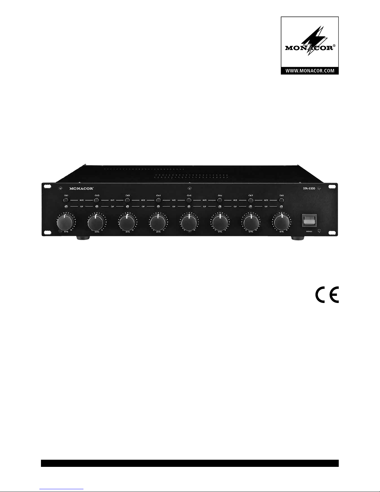
Digital-PA-Verstärker
mit 4 oder 8 Kanälen
Digital PA Amplifier
with 4 or 8 Channels
STA-450D
Bestell-Nr. • Order No. 25.2350
STA-850D
Bestell-Nr. • Order No. 25.2360

2
Deutsch ...........Seite 4
English ............Page 6
Français ...........Page 8
Italiano............Pagina 10
Español ...........Página 12
Polski .............Strona 14
Nederlands ........Pagina 16
Dansk .............Sida 16
Svenska ...........Sidan 17
Suomi.............Sivulta 17
ELECTRONICS FOR SPECIALISTS ELECTRONICS FOR SPECIALISTS ELECTRONICS FOR SPECIALISTS ELECTRONICS FOR SPECIALISTS
3
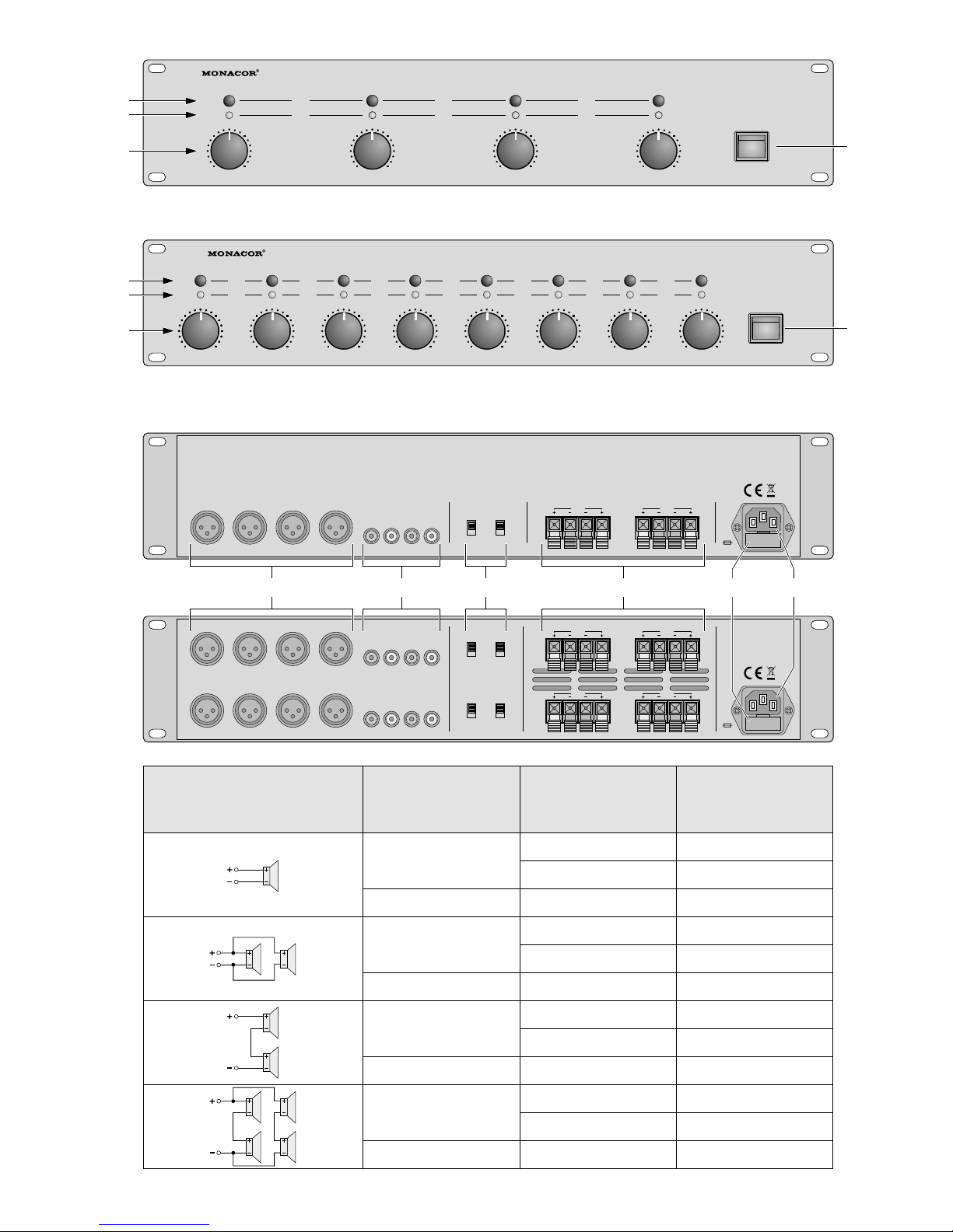
Anschlussmöglichkeit je Ausgang
Connecting possibility per output
Possibilité de branchement pour chaque sortie
Possibilità di connessione per ogni uscita
Betriebsart
Operating mode
Mode de fonctionnement
Modo di funzionamento
Z je Lautsprecher
Z per speaker
Z pour chaque haut-parleur
Z per ogni altoparlante
P
min
je Lautsprecher
P
min
per speaker
P
min
pour chaque haut-parleur
P
min
in per ogni altoparlante
NORMAL
4 Ω 50 W
8 Ω 30 W
BRIDGE
8 Ω 100 W
NORMAL
8 Ω 25 W
16 Ω 15 W
BRIDGE
16 Ω 50 W
NORMAL
4 Ω 15 W
— —
BRIDGE
4 Ω 50 W
NORMAL
4 Ω 12,5 W
8 Ω 7,5 W
BRIDGE
8 Ω 25,0 W
STA-850D
STA-450D
STA-450D
STA-850D
MUTE
CLIP
LEVEL
MUTE
CLIP
LEVEL
MUTE
CLIP
LEVEL LEVEL
0 10 0 10 0 10 0 10
CH1 CH 2 CH3 CH4
POWER
STA-450D
CLIP
MUTE
CLIP
MUTE
CLIP
MUTE
CLIP
MUTE
CLIP
MUTE
CLIP
MUTE
CLIP
MUTE
LEVEL
10
CH1 CH2 CH3 CH4 CH5 CH6 CH7 CH8
POWER
STA-850D
0
LEVEL
100
LEVEL
100
LEVEL LEVEL
100 100
LEVEL
100
LEVEL
100
LEVEL
100
230 V~/
50 Hz
FUSE
CH1 CH2
OUTPUT
BRIDGE
CH3 CH 4
BRIDGE
OPERATING
MODE
CH1/2 CH3/4
NORMAL
BRIDGE
CH1 CH2 CH3 CH4
INPUT
CH4CH3CH2CH1
CH1
CH2
OUTPUT
BRIDGE
CH3 CH 4
BRIDGE
CH5 CH6
BRIDGE
CH7 CH 8
BRIDGE
OPERATING
MODE
CH1/2 CH3/4
NORMAL
BRIDGE
CH5/6 CH7/8
NORMAL
BRIDGE
CH1 CH2 CH3 CH4
INPUT
CH4CH3CH2CH1
CH1 CH2 CH3 CH4
CH8CH7CH6CH5
230
V~/
50 Hz
FUSE
5 6 7
8 9 10
4
4
1
2
3
1
3
2
4
Deutsch
Digital-PA-Verstärker
mit 4 oder 8 Kanälen
Diese Bedienungsanleitung richtet sich an Benutzer ohne besondere Fachkenntnisse. Die
Lautsprecher sollten jedoch nur von Personen
angeschlossen werden, die entsprechendes
Fachwissen dazu haben. Bitte lesen Sie die
Anleitung vor dem Betrieb gründlich durch
und heben Sie sie für ein späteres Nachlesenauf.
Auf der ausklappbaren Seite 3 finden
Sie alle beschriebenen Bedienelemente und
Anschlüsse.
1 Übersicht
1 Taste MUTE zum Stummschalten des zu-
gehörigen Kanals
2 Anzeige CLIP für jeden Kanal
leuchtet bei Übersteuerung des Kanals
3 Lautstärkeregler LEVEL für jeden Kanal
4 Ein- und Ausschalter POWER
5
symmetrische Eingänge als XLR-Buchsen für jeden Kanal; bei Brückenbetrieb
jeweils nur den Eingang mit ungerader
Nummer anschließen
6
asymmetrische Eingänge als Cinch-Buchsen für jeden Kanal; bei Brückenbetrieb
jeweils nur den Eingang mit ungerader
Nummer anschließen
7
Schalter für den Betriebsmodus, jeweils
für ein Kanalpaar
NORMAL = jeder Kanal arbeitet separat
BRIGDE = Brückenbetrieb
8 Lautsprecheranschlüsse
9 Halterung für die Netzsicherung
Eine geschmolzene Sicherung nur durch
eine gleichen Typs ersetzen!
10
Netzbuchse zum Anschluss an eine Steckdose (230 V/ 50 Hz) über das beiliegende
Netzkabel
2 Hinweise für den
sicherenGebrauch
Das Gerät entspricht allen relevanten Richtlinien der EU und trägt deshalb das -Zeichen.
WARNUNG
Das Gerät wird mit lebensge
fährlicher Netzspannung versorgt. Nehmen Sie deshalb niemals selbst Eingriffe am Gerät
vor und stecken Sie nichts
durch die Lüftungsöffnungen!
Es besteht die Gefahr eines
elektrischen Schlages.
•
Das Gerät ist nur zur Verwendung im
Innenbereich geeignet. Schützen Sie es vor
Tropf- und Spritzwasser, hoher Luftfeuchtigkeit und Hitze (zulässiger Einsatztemperaturbereich 0 – 40 °C).
•
Stellen Sie keine mit Flüssigkeit gefüllten
Gefäße, z. B. Trinkgläser, auf das Gerät.
•
Die in dem Gerät entstehende Wärme muss
durch Luftzirkulation abgegeben werden.
Decken Sie darum die Lüftungsöffnungen
des Gehäuses nicht ab.
•
Nehmen Sie das Gerät nicht in Betrieb und
ziehen Sie sofort den Netzstecker aus der
Steckdose,
1. wenn sichtbare Schäden am Gerät oder
am Netzkabel vorhanden sind,
2. wenn nach einem Sturz oder Ähnlichem
der Verdacht auf einen Defekt besteht,
3. wenn Funktionsstörungen auftreten.
Geben Sie das Gerät in jedem Fall zur Reparatur in eine Fachwerkstatt.
•
Ziehen Sie den Netzstecker nie am Kabel
aus der Steckdose, fassen Sie immer am
Stecker an.
•
Verwenden Sie für die Reinigung nur ein
trockenes, weiches Tuch, niemals Wasser
oder Chemikalien.
•
Wird das Gerät zweckentfremdet, nicht
richtig angeschlossen, falsch bedient oder
nicht fachgerecht repariert, kann keine Haftung für daraus resultierende Sach- oder
Personenschäden und keine Garantie für
das Gerät übernommen werden.
Soll das Gerät endgültig aus dem
Betrieb genommen werden, übergeben Sie es zur umweltgerechten
Entsorgung einem örtlichen Recyclingbetrieb.
3 Einsatzmöglichkeiten
Dieser Digital-Verstärker ist optimal für die
gleichzeitige Beschallung mehrerer Räume geeignet. Das Modell STA-450D ist dazu mit vier
Kanälen ausgestattet, das Modell STA-850D
mit acht. Jeder Kanal kann eine Sinusleistung
von 50 W abgeben.
Für eine höhere Ausgangsleistung lassen
sich jeweils zwei Kanäle in Brücke schalten.
Durch die Brückenschaltung kann dann je
Kanalpaar eine Sinusleistung von 100 W abgegeben werden.
4 Aufstellmöglichkeiten
Der Verstärker ist für den Einschub in ein
Rack (482 mm / 19”) vorgesehen, kann aber
auch als Tischgerät verwendet werden. In
jedem Fall muss Luft ungehindert durch alle
Lüftungsöffnungen strömen können, damit
eine ausreichende Kühlung gewährleistet ist.
4.1 Rackeinbau
Für die Montage in ein Rack werden 2 HE
benötigt (HE = Höheneinheit = 44,45 mm).
Damit das Rack nicht kopflastig wird, muss
der Verstärker im unteren Bereich des Racks
eingeschoben werden. Für eine sichere Befestigung reicht die Frontplatte allein nicht aus.
Zusätzlich müssen Seitenschienen oder eine
Bodenplatte das Gerät halten.
Die vom Verstärker abgegebene, erhitzte
Luft muss aus dem Rack austreten können.
Anderenfalls kommt es im Rack zu einem
Hitzestau, wodurch nicht nur der Verstärker,
sondern auch andere Geräte im Rack beschädigt werden können. Bei unzureichendem
Wärmeabfluss in das Rack eine Lüftereinheit
einsetzen.
5 Verstärker anschließen
Alle Anschlüsse dürfen nur bei ausgeschaltetem Gerät hergestellt oder verändert werden!
1) Die Signalquellen (z. B. CD-Spieler, Vor-
verstärker, Mischpult) an die Buchsen
INPUT (5, 6) anschließen.
Die XLR-Buchsen (5) sind für symmetrische Signale beschaltet und benötigen für
eine Vollaussteuerung ein Eingangssignal
von mindestens 550 mV.
Signalquellen mit asymmetrischen Signalen an die Cinch-Buchsen (6) anschließen. Für eine Vollaussteuerung wird ein
Signal von mindestens 1 V benötigt.
Bei den Kanalpaaren, die im Brückenbetrieb arbeiten sollen (☞Kap. 6.1), jeweils nur den Eingang mit ungerader
Nummer anschließen.
2) Die Lautsprecher an die Klemmen OUT-
PUT (8) anschließen. Die erforderliche
Nennbelastbarkeit (P
min
) der Lautsprecher ist in der Tabelle auf der Seite 3 angegeben.
Bei den Kanälen, die im Normalbetrieb
arbeiten [Schalter (7) in Position NORMAL],
jeweils die gekennzeichnete Ader der Lautsprecherleitung mit der roten Klemme
verbinden und die andere Ader mit der
schwarzen Klemme. Beim Normalbetrieb
wird die größte Ausgangsleistung mit
4-Ω-Lautsprechern erreicht. Lautsprecher
mit einer geringeren Impedanz (Z) dürfen
nicht angeschlossen werden, sonst kann
der Verstärker beschädigt werden. Es können jedoch 8-Ω-Lautsprecher angeschlossen werden, was die Ausgangsleistung
aber etwas verringert.
Bei den Kanalpaaren, die im Brücken-
betrieb arbeiten [Schalter (7) in Position
BRIGDE], jeweils die gekennzeichnete Ader
der Lautsprecherleitung mit der linken,
roten Klemme des Kanalpaares verbinden und die andere Ader mit der rechten,
roten Klemme (siehe Aufdruck BRIDGE an
den Klemmen). Im Brückenbetrieb wird
die größte Ausgangsleistung mit einem
8-Ω-Lautsprecher erreicht. Lautsprecher
mit einer geringeren Impedanz (Z) dürfen nicht angeschlossen werden, sonst
kann der Verstärker beschädigt werden.
Es können jedoch Lautsprecher mit einer
größeren Impedanz angeschlossen werden, was die Ausgangsleistung aber etwas
verringert.
3)
Das Netzkabel erst in die Netzbuchse (10)
und dann den Netzstecker des Kabels in
eine Steckdose (230 V/ 50 Hz) stecken.
5
Deutsch
Diese Bedienungsanleitung ist urheberrechtlich für MONACOR ® INTERNATIONAL GmbH & Co. KG
geschützt. Eine Reproduktion für eigene kommerzielle Zwecke – auch auszugsweise – ist untersagt.
6 Bedienung
6.1 Betriebsart wählen
Mit den Schaltern OPERATING MODE (7)
für jedes Kanalpaar einzeln die gewünschte
Betriebsart wählen:
NORMAL = Normalbetrieb, bei dem jeder
Kanal eines Kanalpaares separat arbeitet, d. h. jeder Kanal erhält ein eigenes
Eingangssignal, das mit 50 W Sinusleistung (an 4 Ω) am zugehörigen Ausgang
zur Verfügung steht.
BRIDGE = Brückenbetrieb, bei dem die Kanäle
eines Kanalpaares zur Leistungsverdopplung in Brücke zusammengeschaltet sind.
An den zugehörigen Ausgangsklemmen
stehen 100 W (an 8 Ω) zur Verfügung. Das
Eingangssignal jeweils nur auf die Buchse
mit der zugehörigen ungeraden Nummer
geben.
6.2 Verstärker ein- / ausschalten
Zur Vermeidung von lauten Schaltgeräuschen
den Endverstärker in einer Verstärkeranlage
immer nach allen anderen Geräten einschalten und ihn nach dem Betrieb als erstes Gerät
wieder ausschalten. Vor dem ersten Einschalten die Regler LEVEL (3) ganz nach links auf
Null drehen.
Den Verstärker mit dem Schalter POWER
(4) einschalten. Der Schalter leuchtet als Betriebsanzeige.
6.3 Lautstärke einstellen
Kanalstummschalten
1)
Die Ausgänge der Signalquellen (z. B.
Mischpult, Vorverstärker) auf den Nennpegel (0 dB) oder auf das größte unverzerrte Ausgangssignal aussteuern.
2)
Die Regler LEVEL (3) der benutzten Kanäle so weit aufdrehen, bis die maximal
gewünschte Lautstärke erreicht ist. Die
Regler der nicht verwendeten Kanäle auf
Null drehen.
Bei den Kanalpaaren, die im Brückenbetrieb arbeiten, die Lautstärke nur mit
dem zugehörigen linken Regler (CHANNEL
1, 3, 5 oder 7) einstellen. Den anderen
Regler auf Null stellen; er ist ohne Funktion.
VORSICHT
Stellen Sie die Lautstärke am
Verstärker nie sehr hoch ein.
Hohe Lautstärken können
auf Dauer das Gehör schädi-
gen! Das Ohr gewöhnt sich
an große Lautstärken und
empfindet sie nach einiger
Zeit als nicht mehr so hoch.
Darum eine hohe Lautstärke
nach der Gewöhnung nicht
weiter erhöhen.
Leuchtet eine der roten Anzeigen CLIP (2)
kurz auf, ist die maximal mögliche Lautstärke erreicht. Leuchtet sie öfter kurz auf,
wird der Kanal übersteuert. In diesem Fall
den zugehörigen Regler etwas zurückdrehen.
3)
Jeder Kanal lässt sich separat stummschalten, z. B. wenn für eine Ansprache die Hintergrundmusik stört. Dazu die zugehörige
Taste MUTE (1) drücken.
Bei den Kanalpaaren, die im Brückenbetrieb arbeiten, braucht jeweils nur die
entsprechende linke Taste MUTE (CHANNEL 1, 3, 5 oder 7) gedrückt zu werden.
Die andere Taste ist ohne Funktion.
7 Technische Daten
Modell STA-450D STA-850D
Sinus-Ausgangsleistung
Normalbetrieb an 4 Ω
Normalbetrieb an 8 Ω
Brückenbetrieb an 8 Ω
maximale Gesamtleistung
4 × 50 W
4 × 30 W
2 × 100 W
300 W
8 × 50 W
8 × 30 W
4 × 100 W
600 W
Eingangsempfindlichkeit für Nennleistung
XLR-Buchsen
Cinch-Buchsen
Eingangsimpedanz
550 mV
1 V
20 kΩ
Frequenzbereich 10 – 20 000 Hz
Übersprechdämpfung > 45 dB
Ausgangsschaltung Class D
Einsatztemperatur
0 – 40 °C
Stromversorgung
max. Leistungsaufnahme
230 V/ 50 Hz
300 VA
230 V/ 50 Hz
600 VA
Abmessungen (B × H × T)
482 × 89 × 330 mm
2 HE (Höheneinheiten)
Gewicht
7,2 kg 10,5 kg
Änderungen vorbehalten.
6
English
Digital PA Amplifier
with 4 or 8 Channels
These instructions are intended for users
without any specific technical knowledge.
The speakers, however, should only be connected by persons with the corresponding
technical knowledge. Please read these
instructions carefully prior to operating the
unit and keep them for later reference.
All operating elements and connections
described can be found on the fold-out
page3.
1 Operating Elements
andConnections
1 Button MUTE to mute the corresponding
channel
2 Indicator CLIP for each channel
lights up when the channel is overloaded
3 Volume control LEVEL for each channel
4 Switch POWER
5
Balanced inputs as XLR jacks for each
channel; in case of bridge mode, only
connect the odd-numbered input
6 Unbalanced inputs as RCA jacks for each
channel; in case of bridge mode, only
connect the odd-numbered input
7 Switch for the operating mode, one for
each channel pair
NORMAL = each channel operates sepa-
rately
BRIDGE = bridge mode
8 Speaker terminals
9 Support for the mains fuse
Only replace a blown fuse by one of the
same type!
10
Mains jack for connection to a socket
(230 V/ 50 Hz) via the supplied mains cable
2 Safety Notes
The unit corresponds to all relevant directives
of the EU and is therefore marked with .
WARNING The unit is supplied with haz-
ardous mains voltage. Leave
servicing to skilled personnel
only and do not insert anything
into the air vents! Inexpert
handling may result in electric
shock.
•
The unit is suitable for indoor use only. Pro
tect it against dripping water and splash
water, high air humidity, and heat (admissible ambient temperature range 0 – 40 °C).
•
Do not place any vessels filled with liquid,
e. g. drinking glasses, on the unit.
•
The heat being generated in the unit must
be dissipated by air circulation; never cover
the air vents of the housing.
•
Do not set the unit into operation, and immediately disconnect the mains plug from
the mains socket if
1. there is visible damage to the unit or to
the mains cable,
2.
a defect might have occurred after a drop
or similar accident,
3. malfunctions occur.
The unit must in any case be repaired by
skilled personnel.
•
Never pull the mains cable to disconnect
the mains plug from the mains socket,
always seize the plug.
•
For cleaning only use a dry, soft cloth, never
use chemicals or water.
•
No guarantee claims for the unit and no
liability for any resulting personal damage
or material damage will be accepted if the
unit is used for other purposes than originally intended, if it is not correctly connected or operated, or if it is not repaired
in an expert way.
•
Important for U. K. Customers!
The wires in this mains lead are coloured
in accordance with the following code:
green / yellow = earth
blue = neutral
brown = live
As the colours of the wires in the mains
lead of this appliance may not correspond
with the coloured markings identifying the
terminals in your plug, proceed as follows:
1.
The wire which is coloured green and yel
low must be connected to the terminal in
the plug which is marked with the letter
E or by the earth symbol ⏚, or coloured
green or green and yellow.
2.
The wire which is coloured blue must
be connected to the terminal which is
marked with the letter N or coloured
black.
3. The wire which is coloured brown must
be connected to the terminal which is
marked with the letter L or coloured red.
Warning – This appliance must be earthed.
If the unit is to be put out of operation definitively, take it to a local
recycling plant for a disposal which
is not harmful to the environment.
3 Applications
This digital amplifier is ideally suited for
simultaneous PA application in several rooms.
For this purpose, model STA-450D is equipped
with four channels, model STA-850D with
eight channels. Each channel is able to deliver
an RMS power of 50 W.
For a higher output power, two channels
each can be bridged. Due to the bridge circuit,
an RMS power of 100 W can be delivered per
channel pair.
4 Setting up the Amplifier
The amplifier is designed for installation into
a rack (482 mm / 19”) but can also be used as
a tabletop unit. In order to ensure sufficient
cooling of the amplifier, air must always be
able to flow freely through all air vents.
4.1 Rack installation
For rack installation, the amplifier requires
2 RS (RS = rack space = 44.45 mm). To prevent
the rack from becoming top-heavy, insert the
amplifier into the lower section of the rack.
The front plate is not sufficient for fixing the
amplifier safely; additionally use lateral rails or
a bottom plate to secure the amplifier.
The hot air given off by the amplifier must
be dissipated from the rack; otherwise heat
will accumulate in the rack which may not
only damage the amplifier but also other units
in the rack. In case of insufficient heat dissipation, install a ventilation unit into the rack.
5 Connecting the Amplifier
All connections must only be made or
changed with the unit switched off!
1)
Connect the signal sources (e. g. CD
player, preamplifier, mixer) to the jacks
INPUT (5, 6).
The XLR jacks (5) are designed for balanced signals and, for rated power, require
an input signal of 550 mV as a minimum.
Connect signal sources with unbalanced signals to the RCA jacks (6). For
rated power, a signal of 1 V as a minimum
is required.
For channel pairs intended for bridge
mode (☞ chapter 6.1), only connect the
odd-numbered input.
2)
Connect the speakers to the terminals
OUTPUT (8). The table on page 3 shows
the required power rating (P
min
) of the
speakers.
For channels operating in normal
mode [switch (7) in position NORMAL],
connect the marked core of the speaker
cable to the red terminal and the other
core to the black terminal. In normal mode,
the highest output power will be reached
with 4 Ω speakers. Speakers with lower
impedance (Z) must not be connected; the
amplifier may be damaged. 8 Ω speakers
may be connected; in this case, the output
power will slightly decrease.
For channel pairs operating in bridge
mode [switch (7) in position BRIDGE],
connect the marked core of the speaker
cable to the left, red terminal of the channel pair and the other core to the right,
red terminal (see imprint BRIDGE at the
terminals). In bridge mode, the maximum
output power will be reached with an 8 Ω
speaker. Speakers with lower impedance
(Z) must not be connected; the amplifier
may be damaged. Speakers with higher
impedance may be connected; in this case,
the output power will slightly decrease.
3)
First connect the mains cable to the mains
jack (10) and then the mains plug of the
cable to a socket (230 V/ 50 Hz).
 Loading...