

Page 1
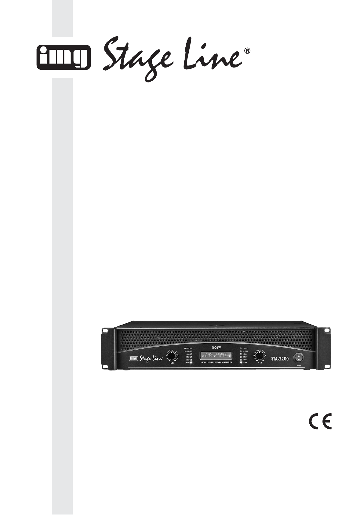
STA-2200 Best.-Nr. 25.0490
PA-STEREO-VERSTÄRKER
PA STEREO AMPLIFIER
AMPLIFICATEUR STEREO PA
AMPLIFICATORE STEREO PA
BEDIENUNGSANLEITUNG • INSTRUCTION MANUAL • MODE D’EMPLOI • ISTRUZIONI PER L’USO
MANUAL DE INSTRUCCIONES • INSTRUKCJA OBSŁUGI • VEILIGHEIDSVOORSCHRIFTEN
SIKKERHEDSOPLYSNINGER • SÄKERHETSFÖRESKRIFTER • TURVALLISUUDESTA
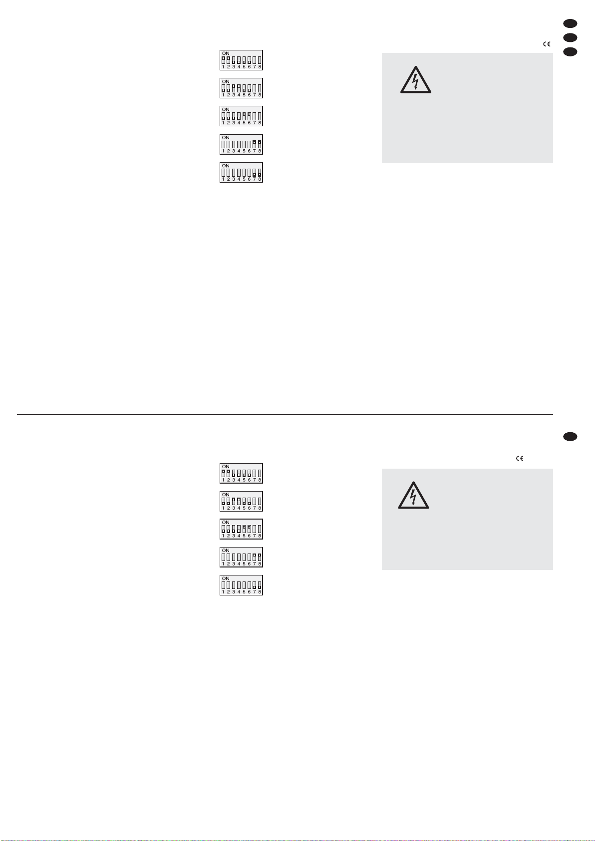
Page 2
2
wwwwww..iimmggssttaaggeelliinnee..ccoomm
Bevor Sie einschalten …
Wir wünschen Ihnen viel Spaß mit Ihrem neuen Gerät
von „img Stage Line“. Bitte lesen Sie diese Bedienungsanleitung vor dem Betrieb gründlich durch. Nur so lernen
Sie alle Funktionsmöglichkeiten kennen, vermeiden
Fehlbedienungen und schützen sich und Ihr Gerät vor
eventuellen Schäden durch unsachgemäßen Gebrauch.
Heben Sie die Anleitung für ein späteres Nachlesen auf.
Der deutsche Text beginnt auf der Seite 4.
Before switching on …
We wish you much pleasure with your new “img Stage
Line” unit. Please read these operating instructions carefully prior to operating the unit. Thus, you will get to know
all functions of the unit, operating errors will be prevented, and yourself and the unit will be protected
against any damage caused by improper use. Please
keep the oper ating instructions for later use.
The English text starts on page 4.
Avant toute installation …
Nous vous souhaitons beaucoup de plaisir à utiliser cet
appareil “img Stage Line”. Lisez ce mode dʼemploi entièrement avant toute utilisation. Uniquement ainsi, vous
pourrez apprendre lʼensemble des possibilités de fonctionnement de lʼappareil, éviter toute manipulation erronée
et vous protéger, ainsi que lʼappareil, de dommages éventuels engendrés par une utilisation inadaptée. Conservez la notice pour pouvoir vous y reporter ultérieurement.
La version française se trouve page 9.
Prima di accendere …
Vi auguriamo buon divertimento con il vostro nuovo
apparecchio di “img Stage Line”. Leggete attentamente
le istruzioni prima di mettere in funzione lʼapparecchio.
Solo così potete conoscere tutte le funzionalità, evitare
comandi sbagliati e proteggere voi stessi e lʼapparecchio
da eventuali danni in seguito ad un uso improprio. Conservate le istruzioni per poterle consultare anche in
futuro.
Il testo italiano inizia a pagina 9.
D
A
CH
GB
Voor u inschakelt …
Wij wensen u veel plezier met uw nieuwe apparaat van
“img Stage Line”. Lees de veiligheidsvoorschriften grondig door, alvorens het apparaat in gebruik te nemen. Zo
behoedt u zichzelf en het apparaat voor eventuele
schade door ondeskundig gebruik. Bewaar de handleiding voor latere raadpleging.
De veiligheidsvoorschriften vindt u op pagina 20.
Før du tænder …
Vi håber, du bliver glad for dit nye “img Stage Line” produkt. Læs sikkerhedsanvisningerne nøje før ibrugtagning, for at beskytte Dem og enheden mod skader, der
skyldes forkert brug. Gem manualen til senere brug.
Sikkerhedsanvisningerne findes på side 20.
Innan du slår på enheten …
Vi önskar dig mycket glädje med din nya “img Stage Line”
produkt. Läs igenom säkerhetsföre skrifterna innan en heten tas i bruk för att undvika skador till följd av felaktig
hantering. Behåll instruktionerna för framtida bruk.
Säkerhetsföreskrifterna återfinns på sidan 20.
Ennen kytkemistä …
Toivomme Sinulle paljon miellyttäviä hetkiä uuden “img
Stage Line” laitteen kanssa. Ennen laitteen käyttöä pyydämme Sinua huolellisesti tutustumaan turvallisuusohjeisiin. Näin vältyt vahingoilta, joita virheellinen laitteen
käyttö saattaa aiheuttaa. Ole hyvä ja säilytä käyttöohjeet
myöhempää tarvetta varten.
Turvallisuusohjeet löytyvät sivulta 21.
F
B
CH
I
Antes de la utilización …
Le deseamos una buena utilización para su nuevo aparato “img Stage Line”. Por favor, lea estas instrucciones
de uso atentamente antes de hacer funcionar el aparato.
De esta manera conocerá todas las funciones de la unidad, se prevendrán errores de operación, usted y el aparato estarán protegidos en contra de todo daño causado
por un uso inadecuado. Por favor, guarde las instrucciones para una futura utilización.
El texto en español empieza en la página 14.
E
NL
Przed uruchomieniem …
Życzymy zadowolenia z nowego produktu “img Stage
Line”. Dzięki tej instrukcji obsługi będą państwo w stanie
poznać wszystkie funkcje tego urządzenia. Stosując się
do instrukcji unikną państwo błędów i ewentualnego
uszkodzenia urządzenia na skutek nieprawidłowego
użytkowania. Prosimy zachować instrukcję.
Tekst polski zaczyna się na stronie 14.
PL
DK
S
FIN
B
Page 3
3
123 45 6
78910111213 1415
Anschlussmöglichkeit
je Ausgang
Connecting possibility
per output
Betriebsart
Mode
Z je Lautsprecher
Z per speaker
PMIN je Lautsprecher
PMIN per speaker
+
-
STEREO, PARALLEL 4 Ω 1100W
STEREO, PARALLEL 8 Ω 700 W
BRIDGED 8 Ω 2000W
+
-
+
-
STEREO, PARALLEL 8 Ω 550 W
STEREO, PARALLEL 16 Ω 350W
BRIDGED 16 Ω 1000 W
+
-
+
-
STEREO, PARALLEL 4 Ω 350 W
BRIDGED 4 Ω 1000W
BRIDGED 8 Ω 700 W
+
-
+
-
+
-
+
-
STEREO, PARALLEL 4 Ω 275 W
STEREO, PARALLEL 8 Ω 175 W
BRIDGED 8 Ω 500 W
Page 4
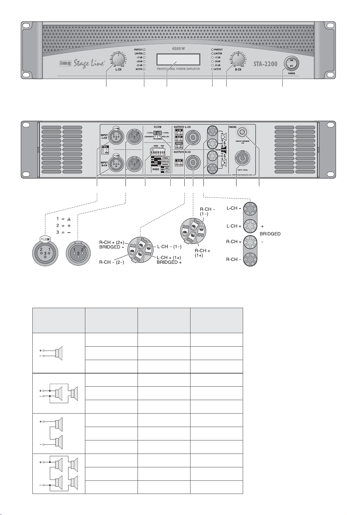
All operating elements and connections de scribed can be found on the fold-out page 3.
1
Operating Elements and Connections
1.1 Front panel
1 Volume control for the left channel L-CH
2 Status LEDs for the left channel:
PROTECT lights up with activated protective
circuit (the connection to the speakers is separated):
1. after switching-on for a short time
2. in case of overload/overheating (e. g. also by
short circuit at the output)
3. in case of DC voltage at the output
LIMITER lights up when the input signal is too
high and limited by the limiter
ACTIVE lights up as a power indication
-
25 dB, -20 dB, -15 dB show the input level
3 LC display for operating mode and temperatures
4 Status LEDs for the right channel (
item 2)
5 Volume control for the right channel R-CH
6 POWER switch
1.2 Rear panel
7 Balanced inputs: XLR jacks for the left channel
(L-CH) and the right channel (R-CH)
8 XLR feed-through outputs to pass on the input
signals e. g. to an additional amplifier
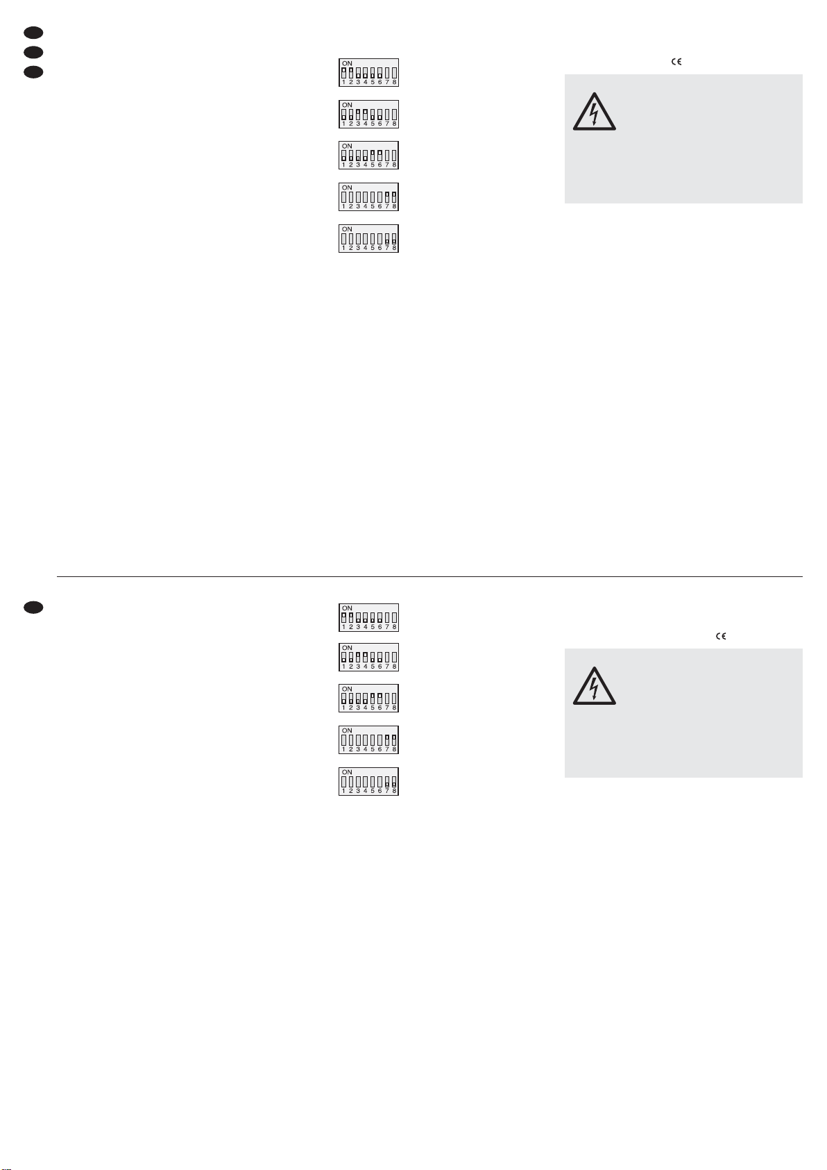
9 DIP switches for selecting the operating mode
and for separating signal ground and housing
ground:
operating mode STEREO
operating mode PARALLEL
operating mode BRIDGE
signal ground connected to
housing ground
signal ground and housing
ground separated (groundlift)
10 Switch FILTER with three positions
SUBWOOFER: low pass filter with -6 dB at 120 Hz
SATELLITE: high pass filter with -6 dB at 120Hz
FULLRANGE: no filter
11 Speaker output: Speakon
®
jack, depending on
plug configuration for the left channel, the right
channel, or for bridge mode
12 Speaker output: Speakon
®
jack for the right
channel
13 Speaker outputs: screw terminals
14 PowerCon
®
mains jack for connection to a
socket (230 V~/50 Hz) with earthed contact e.g.
via the mains cable AAC-115P
Important: The PowerCon
®
plug-in connection
must not be connected or disconnected when carrying any voltage or
load. (Switch off the unit beforehand!)
15 Protective switch to protect the unit; to reset the
released switch, press down the button
2 Safety Notes
The unit corresponds to all relevant directives of the
EU and is therefore marked with .
It is essential to observe the following items:
G
The unit is suitable for indoor use only. Protect it
against dripping water and splash water, high air
humidity, and heat (admissible ambient temperature range 0 – 40 °C).
G
Do not place any vessels filled with liquid, e. g.
drinking glasses, on the unit.
G
The heat being generated in the unit must be carried off by air circulation. Therefore, the air vents
at the housing must not be covered.
G
Do not set the unit into operation, and immediately
disconnect the mains plug from the mains socket
if
1. there is visible damage to the unit or to the
mains cable,
2. a defect might have occurred after a drop or
similar accident,
3. malfunctions occur.
The unit must in any case be repaired by skilled
personnel.
G
Never pull the mains cable to disconnect the
mains plug from the mains socket, always seize
the plug.
WARNING The unit is supplied with hazardous
mains voltage. Leave servicing to
skilled personnel only and do not
insert anything through the air vents!
This may cause an electric shock
hazard.
There is a hazard of contact at the speaker connections with a dangerous voltage during operation. All connections must only be made or
changed with the unit switched off.
D
A
CH
4
GB
Auf der ausklappbaren Seite 3 finden Sie alle
beschriebenen Bedien elemente und Anschlüsse.
1 Übersicht der Bedienelemen te
und Anschlüsse
1.1 Frontseite
1 Lautstärkeregler für den linken Kanal L-CH
2 Status-LEDs für den linken Kanal:
PROTECT leuchtet bei aktivierter Schutzschaltung (die Verbindung zu den Lautsprechern ist
getrennt):
1. nach dem Einschalten für kurze Zeit
2. bei Überlastung/ Überhitzung (auch z. B. durch
Kurzschluss am Ausgang)
3. bei Gleichspannung am Ausgang
LIMITER leuchtet wenn das Eingangssignal zu
groß ist und vom Limiter begrenzt wird
ACTIVE leuchtet als Betriebsanzeige
-
25 dB, -20 dB, -15 dB zeigen den Eingangs -
pegel an
3 LC-Display für Betriebsart und Temperaturen
4 Status-LEDs für den rechten Kanal (
Punkt 2)
5 Lautstärkeregler für den rechten Kanal R-CH
6 Ein-/Ausschalter POWER
1.2 Rückseite
7 Symmetrische Eingänge als XLR-Buchsen für
den linken (L-CH) und rechten (R-CH) Kanal
8 XLR-Durchschleifausgänge zum Weiterleiten
der Eingangssignale z. B. zu einem zusätzlichen
Verstärker
9 DIP-Schalter zur Wahl der Betriebsart und zur
Trennung von Signal- und Gehäusemasse:
Betriebsart STEREO
Betriebsart PARALLEL
Betriebsart BRIDGE
Signalmasse mit Gehäusemasse verbunden
Signalmasse und Gehäusemasse getrennt (groundlift)
10 Schalter FILTER mit den drei Positionen
SUBWOOFER: Tiefpassfilter mit
-
6 dB bei 120Hz
SATELLITE: Hochpassfilter mit
-
6 dB bei 120Hz
FULLRANGE: kein Filter
11 Lautsprecherausgang als Speakon
®
-Buchse, je
nach Steckerbelegung für den linken Kanal, den
rechten Kanal oder für den Brückenbetrieb
12 Lautsprecherausgang als Speakon
®
-Buchse für
den rechten Kanal
13 Lautsprecherausgänge als Schraubklemmen
14 PowerCon
®
-Netzbuchse zum Anschluss an eine
Steckdose (230 V~ / 50 Hz) mit Schutzkontakt
z. B. über das Netzkabel AAC-115P
Wichtig: Die PowerCon
®
-Steckverbindung darf
nicht unter Spannung oder Last verbunden oder getrennt werden. (Das
Gerät vorher ausschalten!)
15 Schutzschalter zur Geräteabsicherung; zum
Zurücksetzen des ausgelösten Schalters den
Knopf hineindrücken
2 Hinweise für den sicheren Gebrauch
Das Gerät entspricht allen relevanten Richtlinien der
EU und ist deshalb mit gekennzeichnet.
Beachten Sie auch unbedingt die folgenden Punkte:
G
Verwenden Sie das Gerät nur im In nen bereich
und schützen Sie es vor Tropf- und Spritzwasser,
hoher Luftfeuchtigkeit und Hitze (zu lässiger Einsatztemperaturbereich 0 – 40 °C).
G
Stellen Sie keine mit Flüssigkeit gefüllten Gefäße,
z. B. Trinkgläser, auf das Gerät.
G
Die in dem Gerät entstehende Wärme muss durch
Luftzirkulation abgegeben werden. Decken Sie
darum die Lüftungsöffnungen des Gehäuses nicht
ab.
G
Nehmen Sie das Gerät nicht in Betrieb und ziehen
Sie sofort den Netzstecker aus der Steckdose,
1. wenn sichtbare Schäden am Gerät oder an der
Netzanschlussleitung vorhanden sind,
2. wenn nach einem Sturz oder Ähnlichem der
Verdacht auf einen Defekt besteht,
3. wenn Funktionsstörungen auftreten.
Geben Sie das Gerät in jedem Fall zur Reparatur
in eine Fachwerkstatt.
G
Ziehen Sie den Netzstecker nie am Kabel aus der
Steckdose, fassen Sie immer am Stecker an.
G
Verwenden Sie für die Reinigung nur ein trockenes, weiches Tuch, niemals Wasser oder Chemikalien.
WARNUNG Das Gerät wird mit lebensgefährlicher
Netzspannung versorgt. Nehmen Sie
deshalb niemals selbst Eingriffe am
Gerät vor und stecken Sie nichts durch
die Lüftungsöffnungen! Es be steht die
Gefahr eines elektrischen Schlages.
Im Betrieb liegt an den Laut sprecheranschlüssen
berührungs ge fährliche Spannung an. Alle An schlüsse nur bei ausgeschaltetem Gerät vornehmen
bzw. verändern.
Page 5
G
For cleaning only use a dry, soft cloth, never use
chemicals or water.
G
No guarantee claims for the unit and no liability for
any resulting personal damage or material damage will be accepted if the unit is used for other
purposes than originally intended, if it is not correctly connected or operated, or not repaired in an
expert way.
3 Applications
This PA stereo amplifier has especially been
designed for stage and disco applications. The
amplifier may be operated in stereo mode, in mono
parallel mode, or in mono bridge mode. With its
class H output circuit it operates more efficiently than
standard amplifiers of class AB technology. Due to a
switchable filter the amplifier may also be used only
for subwoofers or only for the frequency range
exceeding 120 Hz. Extensive protective circuits protect the amplifier and the speakers connected. Two
powerful, temperature-controlled fans supply the
necessary cooling of the amplifier.
4 Setting-Up
The amplifier is provided for installation into a rack
(482 mm/19″), but it may also be used as a table top
unit. In each case air must be allowed to flow freely
through all ventilation slots so that a sufficient cooling is ensured.
4.1 Rack installation
For rack mounting 2 rs (rack spaces) = 89 mm are
required. The heated air blown out by the amplifier at
the rear must be able to dissipate from the rack, otherwise a heat accumulation will occur in the rack
which may not only damage the amplifier but also
other units in the rack. In case the heat is not dissipated sufficiently, a fan unit has to be inserted into
the rack.
To prevent top-heaviness of the rack, the amplifier must be inserted in the lower part of the rack. To
ensure a safe fixing, the front panel alone is not sufficient. In addition, the unit must be fastened at the
rear side or be supported by means of lateral rails or
a bottom plate.
5 Connecting the Amplifier
All connections must only be made or changed with
the unit switched off!
1) Connect the output of a preamplifier or mixer to
the XLR jacks INPUTS (7). The jacks are
designed for balanced signals; the contact con-
figuration is shown in fig. 2. For connection of
sources with unbalanced signals use an adapter
with the XLR contacts 1 and 3 bridged (e. g. the
adapter MCA-15/2 from “img Stage Line”: 2-pole
6.3 mm inline jack to XLR plug).
The input signal should have line level. For
rated power of the amplifier an input signal of 1 V
is required as a minimum.
For bridge mode or parallel mode only connect
the input of the left channel L-CH.
Via the feed-through outputs (8) which are
directly connected to the respective input jack (7)
the signal can be fed e. g. to an additional amplifier.
2) The maximum output power is reached in stereo
mode and in parallel mode when connecting 4 Ω
speakers (minimum admissible load impedance
at rated power). It is also possible to connect 8 Ω
speakers, however, in this case the output power
will slightly decrease. In bridge mode the maximum output power will be reached with an 8 Ω
speaker (minimum admissible load impedance at
rated power in bridge operation). The required
power rating (P
MIN) of the speakers is listed in the
table fig. 3.
As long as in stereo or parallel operation the
RMS output power of 750 W per channel is not
exceeded, the operation with 2 Ω load is possible.
A bridge operation at a 4 Ω load is possible up to
an RMS output power of 1500 W.
Connect the speakers to the Speakon
®
jacks
(11, 12), pin configuration of the plug see fig. 2, or
to the screw terminals (13).
After connecting a Speakon
®
plug to the jack,
turn it clockwise until it locks into place. For
removing it later, retract the latch lock at the plug
and turn the plug counter-clockwise.
If the screw terminals are used, ensure that
the cable ends are not stripped too far and that no
bare wires protrude (hazard of contact and short
circuit).
When connecting the speakers, pay attention
to the same polarity of all speakers.
The Speakon
®
jack of the output L-CH (11) is
additionally provided with the signals of the right
output R-CH so that it is also possible to connect
both speakers via a 4-pole cable to this jack.
For bridge mode connect the positive contact
of the speaker to the positive terminal (13) of the
left output L-CH and the negative contact of the
speaker to the positive terminal of the right output
R-CH [see fig. 2]. (By the signal inversion in
bridge mode, the positive terminal of the right output becomes the negative connection for the
speaker.) The speaker can alternatively also be
If the unit is to be put out of operation definitively, take it to a local recycling plant for a
disposal which is not harmful to the environment.
D
A
CH
5
GB
G
Wird das Gerät zweckentfremdet, nicht richtig
bedient, falsch angeschlossen oder nicht fach gerecht repariert, kann keine Haftung für daraus
resultierende Sach- oder Personenschäden und
keine Garantie für das Gerät übernommen werden.
3 Einsatzmöglichkeiten
Dieser PA-Stereo-Verstärker ist speziell für den Einsatz auf der Bühne und in der Diskothek konzipiert.
Er kann im Stereobetrieb, im Mono-Parallelbetrieb
oder im Mono-Brückenbetrieb genutzt werden. Mit
seiner Class-H-Ausgangsschaltung arbeitet er effizienter als herkömmliche Verstärker in Class-ABTechnologie. Durch ein schaltbares Filter kann der
Verstärker auch nur für Subwoofer oder nur für den
Frequenzbereich oberhalb von 120 Hz eingesetzt
werden. Umfangreiche Schutzschaltungen schützen
den Verstärker und die angeschlossenen Lautsprecher. Zwei leistungsstarke, temperaturgeregelte Lüfter sorgen für die nötige Kühlung des Verstärkers.
4 Aufstellmöglichkeiten
Der Verstärker ist für den Einschub in ein Rack
(482 mm/19″) vorgesehen, kann aber auch als
Tischgerät ver wendet werden. In jedem Fall muss
Luft ungehindert durch alle Lüftungsschlitze strömen
können, damit eine ausreichende Kühlung gewährleistet ist.
4.1 Rackeinbau
Für die Rackmontage werden 2 HE (Höheneinheiten) = 89 mm benötigt. Die vom Verstärker rückseitig ausgeblasene, erhitzte Luft muss aus dem Rack
austreten können. Anderenfalls kommt es im Rack
zu einem Hitzestau, wodurch nicht nur der Verstärker, sondern auch andere Geräte im Rack beschädigt werden können. Bei unzureichendem Wärmeabfluss in das Rack eine Lüftereinheit einsetzen.
Damit das Rack nicht kopflastig wird, muss der
Verstärker im unteren Bereich des Racks eingeschoben werden. Für eine sichere Befestigung
reicht die Frontplatte allein nicht aus. Zusätzlich
muss das Gerät an der Rückseite befestigt oder
über Seitenschienen oder eine Bodenplatte gehalten werden.
5 Verstärker anschließen
Alle Anschlüsse dürfen nur bei ausgeschaltetem
Gerät hergestellt oder verändert werden!
1) An die XLR-Buchsen INPUTS (7) den Ausgang
eines Vorverstärkers oder eines Mischpults
anschließen. Die Buchsen sind für symmetrische
Signale beschaltet; die Kontaktbelegung ist in
Abbildung 2 dargestellt. Für den Anschluss von
Quellen mit asymmetrischen Signalen einen
Adapter verwenden, bei dem die XLR-Kontakte 1
und 3 gebrückt sind (z. B. den Adapter MCA-15/2
von „img Stage Line“: 2-polige 6,3-mm-Klinken -
kupplung auf XLR-Stecker).
Das Eingangssignal sollte Line-Pegel aufweisen. Für eine Vollaussteuerung des Verstärkers
ist ein Eingangssignal von mindestens 1 V erforderlich.
Für den Brücken- oder Parallelbetrieb nur den
Eingang des linken Kanals L-CH anschließen.
Über die Durchschleifausgänge (8), die mit
der jeweiligen Eingangsbuchse (7) direkt verbunden sind, kann das Signal z. B. zu einem zusätzlichen Verstärker weitergeleitet werden.
2) Die größte Ausgangsleistung wird im Stereobetrieb
und im Parallelbetrieb beim An schluss von 4-ΩLautsprechern (minimal zulässige Lastimpedanz
bei Vollaussteuerung) erreicht. Es können auch
8-Ω-Lautsprecher angeschlossen werden, was
die Ausgangsleis tung aber etwas verringert. Im
Brückenbetrieb wird die größte Ausgangsleistung
mit einem 8-Ω-Laut sprecher (minimal zulässige
Lastimpedanz bei Vollaussteuerung im Brückenbetrieb) erreicht. Die erforderliche Nenn belastbarkeit (P
MIN) der Lautsprecher ist in der Tabelle
Abb. 3 aufgeführt.
Solange im Stereo- oder Parallelbetrieb die
Sinus-Ausgangsleistung von 750 W pro Kanal
nicht überschritten wird, ist auch der Betrieb mit
2-Ω-Lasten möglich. Ein Brückenbetrieb an einer
4-Ω-Last ist bis zu einer Sinus-Ausgangsleistung
von 1500 W möglich.
An die Speakon
®
-Buchsen (11, 12), Kontaktbelegung des Steckers siehe Abb. 2, oder an die
Schraub klemmen (13) die Lautsprecher an schließen.
Einen Speakon
®
-Stecker nach dem Einstecken in die Buchse nach rechts drehen, bis er
einrastet. Zum späteren Herausziehen den
Sicherungsriegel am Stecker zurückziehen und
den Stecker nach links drehen.
Werden die Schraubklemmen genutzt, darauf
achten, dass die Kabelenden nicht zu weit abisoliert sind und keine blanken Drähte herausragen
(Berührungs- und Kurzschlussgefahr).
Beim Anschluss der Lautsprecher ist auf die
gleiche Polung aller Lautsprecher zu achten.
Die Speakon
®
-Buchse des Ausgangs L-CH
(11) ist zusätzlich mit den Signalen des rechten
Ausgangs R-CH belegt, so dass es auch möglich
ist, beide Lautsprecher über ein vierpoliges Kabel
an diese Buchse anzuschließen.
Für den Brückenbetrieb den Pluskontakt des
Lautsprechers mit der Plusklemme (13) des linken Ausgangs L-CH verbinden und den Minuskontakt des Lautsprechers mit der Plusklemme
des rechten Ausgangs R-CH [siehe Abb. 2]. (Die
Plusklemme des rechten Ausgangs wird durch
die Signalinvertierung im Brückenbetrieb zum
Minus anschluss für den Lautsprecher.) Der Laut-
Soll das Gerät endgültig aus dem Betrieb
genommen werden, übergeben Sie es zur
umweltgerechten Entsorgung einem örtlichen Recyclingbetrieb.
Page 6
sprecher kann alternativ auch an die Speakon®Buchse L-CH (11) angeschlossen werden. Dabei
entsprechend Abb. 2 die Plusklemme des Lautsprechers an den Kontakt 1+ und die Minus klemme an den Kontakt 2+ des Steckers
anschlie ßen.
In der Tabelle Abb. 3 sind auch Anschluss-
möglichkeiten für mehrere Lautsprecher an
einem Ausgang aufgeführt. Dazu ist jeweils
angegeben, welche Nennbelastbarkeit (P
MIN)
jeder Lautsprecher bei entsprechender Impedanz (Z) mindestens haben muss. Beim Zusammenschalten von mehreren Lautsprechern ist
besonders auf die richtige Verbindung der Plusund Minusanschlüsse zu achten.
Wichtig: Die Gesamtimpedanz an jedem Ausgang darf bei Vollaussteuerung im Stereo- und
Parallelbetrieb 4 Ω, im Brückenbetrieb 8 Ω nicht
unterschreiten!
Solange im Stereo- oder Parallelbetrieb die
Sinus-Ausgangsleistung von 750 W pro Kanal
nicht überschritten wird, ist auch der Betrieb mit
2-Ω-Lasten möglich. Ein Brückenbetrieb an einer
4-Ω-Last ist bis zu einer Sinus-Ausgangsleistung
von 1500 W möglich.
3) Das Gerät wird ohne Netzkabel geliefert. Zum
Anschluss ein Netzkabel mit einem PowerCon
®
Stecker und einem Netzstecker mit Schutzkontakt (z. B. AAC-115P von „img Stage Line“) verwenden.
Zuerst den PowerCon
®
-Stecker in die Netzbuchse (14) stecken und nach rechts drehen, bis
er einrastet und dann den Netzstecker in eine
Steckdose (230 V~/ 50Hz) stecken. Zum Trennen vom Netz zuerst den Netzstecker ziehen und
dann zum Herausziehen des PowerCon®-Steckers dessen Sicherungsriegel zurückziehen und
den Stecker nach links drehen.
Achten Sie auch darauf, dass der Stromkreis,
an den das Gerät angeschlossen wird, entsprechend hoch abgesichert ist (16 A).
6 Bedienung
6.1 Betriebsart wählen
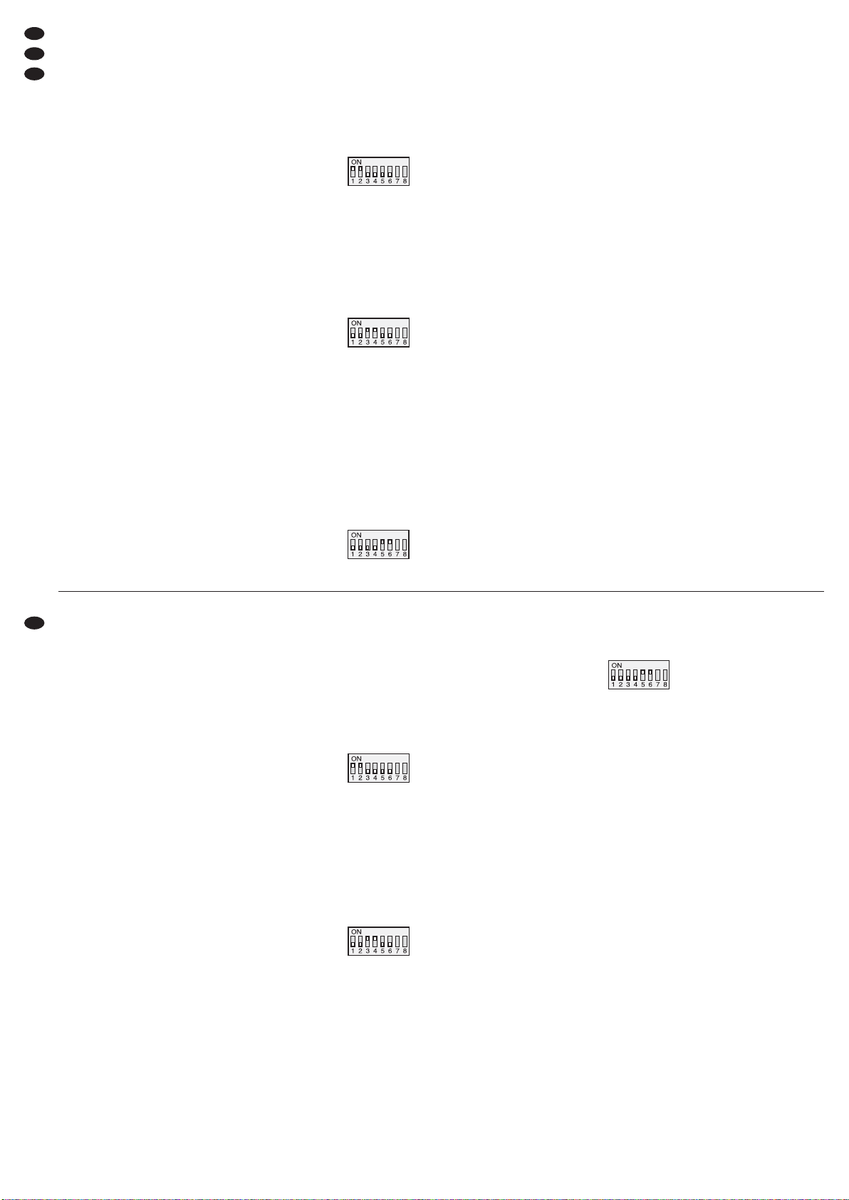
Mit den DIP-Schaltern MODE Nr. 1 – 6 (9) die
gewünschte Betriebsart wählen:
Stereobetrieb –„
MODE STEREO“
Im Stereobetrieb werden beide Kanäle unabhängig
voneinander betrieben.
Schalterkonstellation
STEREO
Parallelbetrieb –„
MODE PARALLEL“
Sollen z. B. zwei Räume mit demselben Mono-Signal beschallt werden und die Lautstärke einzeln einstellbar sein, bietet sich der Parallelbetrieb an.
Das Eingangssignal wird intern vom linken Kanal
zusätzlich auf den rechten Kanal geschaltet. Ein Signal am rechten Eingang wird ignoriert. Die Lautstärkeeinstellung erfolgt für beide Ausgänge separat.
Schalterkonstellation
PARALLEL
Brückenbetrieb –„
MODE BRIDGE“
Der Brückenbetrieb (BRIDGE) dient dazu, an einem
Lautsprecher eine größere Leistung zu erhalten.
Dazu werden beide Verstärkerkanäle zu einem
Monoverstärker kombiniert: Das Eingangssignal am
linken Kanal wird zusätzlich invertiert auf den rechten
Kanal geschaltet. Dadurch verdoppelt sich die Spannung am Ausgang, wenn der Lautsprecher, wie in
Kap. 5 beschrieben, für den Brückenbetrieb angeschlossen ist. Ein Signal am rechten Eingang wird
ignoriert. Die Lautstärkeeinstellung erfolgt für beide
Ausgänge gemeinsam mit dem linken Regler (1).
Schalterkonstellation
BRIDGE
6.2 Filter
Das eingebaute Filter kann als Frequenzweiche für
2-Wege-Lautsprechersysteme (Subwoofer/ Satellite) verwendet werden. Mit dem Schalter FILTER
(10) die dem angeschlossenen Lautsprecher entsprechende Funktion wählen.
Position SUBWOOFER:
Tiefpassfilter mit
-
6 dB bei 120 Hz
für Tieftonlautsprecher
Position SATELLITE:
Hochpassfilter mit
-
6 dB bei 120 Hz
für Mittelhochtonlautsprecher
Position FULLRANGE:
kein Filter für Breitbandlautsprecher
6.3 Ein-/Ausschalten
Zur Vermeidung von lauten Schaltgeräuschen den
Endverstärker in einer Verstärkeranlage immer nach
allen anderen Geräten einschalten und ihn nach
dem Betrieb als erstes Gerät wieder ausschalten.
Vor dem ersten Einschalten die Regler (1 und 5)
ganz nach links auf „-80 dB“ drehen.
Den Verstärker mit dem Schalter POWER (6) einschalten. Die ACTIVE-LEDs (2, 4) leuchten als
Betriebsanzeige und das Display (3) zeigt die
gewählte Betriebsart. Nach dem Einschalten leuchten für kurze Zeit die roten PROTECT-LEDs (2, 4).
In dieser Zeit ist die Einschaltverzögerung zum
Schutz der Lautsprecher aktiviert.
6.4 Pegel einstellen
Den Ausgang des Mischpultes oder Vorverstärkers
auf seinen Nennpegel (0 dB) oder das größte unverzerrte Ausgangssignal aussteuern. Die Regler (1
und 5) so weit aufdrehen, bis die maximal ge wünschte Lautstärke erreicht ist. Die LEDs „-25 dB“,
„-20 dB“ und „-15 dB“ (2, 4) zeigen den eingestellten Eingangspegel an. Leuchten die roten LIMITERLEDs, ist die Begrenzerschaltung aktiv und verhin-
connected to the Speakon®jack L-CH (11).
According to fig. 2 connect the positive terminal of
the speaker to contact 1+ and the negative terminal to contact 2+ of the plug.
Table fig. 3 also shows possibilities of con-
nection for several speakers to one output. In
each case it is stated which power rating (PMIN)
each speaker must have as a minimum with the
corresponding impedance (Z). When interconnecting several speakers, special attention has to
be paid to the correct connection of the positive
and negative terminals.
Important: At rated power, the total impedance
at each output must not fall below 4 Ω in stereo
and parallel operation, and 8 Ω in bridge operation!
As long as in stereo or parallel operation the
RMS output power of 750 W per channel is not
exceeded, the operation with 2 Ω load is possible.
A bridge operation at a 4 Ω load is possible up to
an RMS output power of 1500 W.
3) The unit is supplied without mains cable. For connection, use a mains cable with a PowerCon
®
plug and a mains plug with earthed contact (e. g.
AAC-115P from “img Stage Line”).
First connect the PowerCon®plug to the
mains jack (14) and turn it clockwise until it locks
into place and then connect the mains plug to a
socket (230 V~/ 50 Hz). To separate it from the
mains, first disconnect the mains plug and then,
for removing the PowerCon®plug, retract its latch
lock and turn the plug counter-clockwise.
Make sure that the current circuit the unit is
connected to is provided with a fuse of corresponding high value (16A).
6 Operation
6.1 Selecting the operating mode
Select the desired operating mode with the DIP
switches MODE Nos. 1 to 6 (9):
Stereo mode – display: “
MODE STEREO”
In stereo mode, both channels are operated independently of each other.
switch configuration
STEREO
Parallel mode – display: “
MODE PARALLEL”
Parallel mode is recommended to provide PA applications e. g. for two rooms with the same mono signal and to be capable of adjusting the volume individually.
The input signal is internally switched from the left
channel additionally to the right channel. A signal at
the right input is ignored. The volume is separately
adjusted for both outputs.
switch configuration
PARALLEL
Bridge mode – display: “
MODE BRIDGE”
The bridge mode (BRIDGE) serves to obtain a
higher power at one speaker.
For this purpose both amplifier channels are combined to one mono amplifier: The input signal of the
left channel is additionally switched to the right channel in an inverted way. Thus, the voltage at the output is doubled if the speaker is connected for bridge
mode, as described in chapter 5. A signal at the right
input is ignored. The volume is adjusted with the left
control (1) together for both outputs.
switch configuration
BRIDGE
6.2 Filter
The integrated filter can be used as a crossover network for 2-way speaker systems (subwoofer/satellite). Select the function corresponding to the connected speaker with the switch FILTER (10).
Position SUBWOOFER:
Low pass filter with -6 dB at 120 Hz
for bass speakers
Position SATELLITE:
High pass filter with -6 dB at 120 Hz
for mid-high range speakers
Position FULLRANGE:
no filter for full range speakers
6.3 Switching on/off
To prevent loud switching noise, always switch on
the power amplifier in an amplifier system after all
other units have been switched on and switch it off
first after operation. Prior to first switching-on, set the
controls (1 and 5) to the left stop to “-80 dB”.
Switch on the amplifier with the POWER switch (6).
The ACTIVE LEDs (2, 4) serve as a power indication
and the display (3) shows the selected operating
mode. After switching-on, the red LEDs PROTECT
(2, 4) light up for a short time. During this time the
switch-on delay is activated to protect the speakers.
6
CH
A
D
GB
Page 7
dert die Übersteuerung des Verstärkers. In diesem
Fall die Regler etwas zu rückdrehen.
6.5 Groundlift-Schalter
Ist ohne ein Musiksignal ein störendes Brummen zu
hören, kann eine Masseschleife die Ursache sein.
Masseschleifen können entstehen, wenn zwei
Geräte sowohl über die Signalmasse als auch über
den Schutzleiter der Stromversorgung oder eine leitende Verbindung der Gehäuse im Rack Kontakt
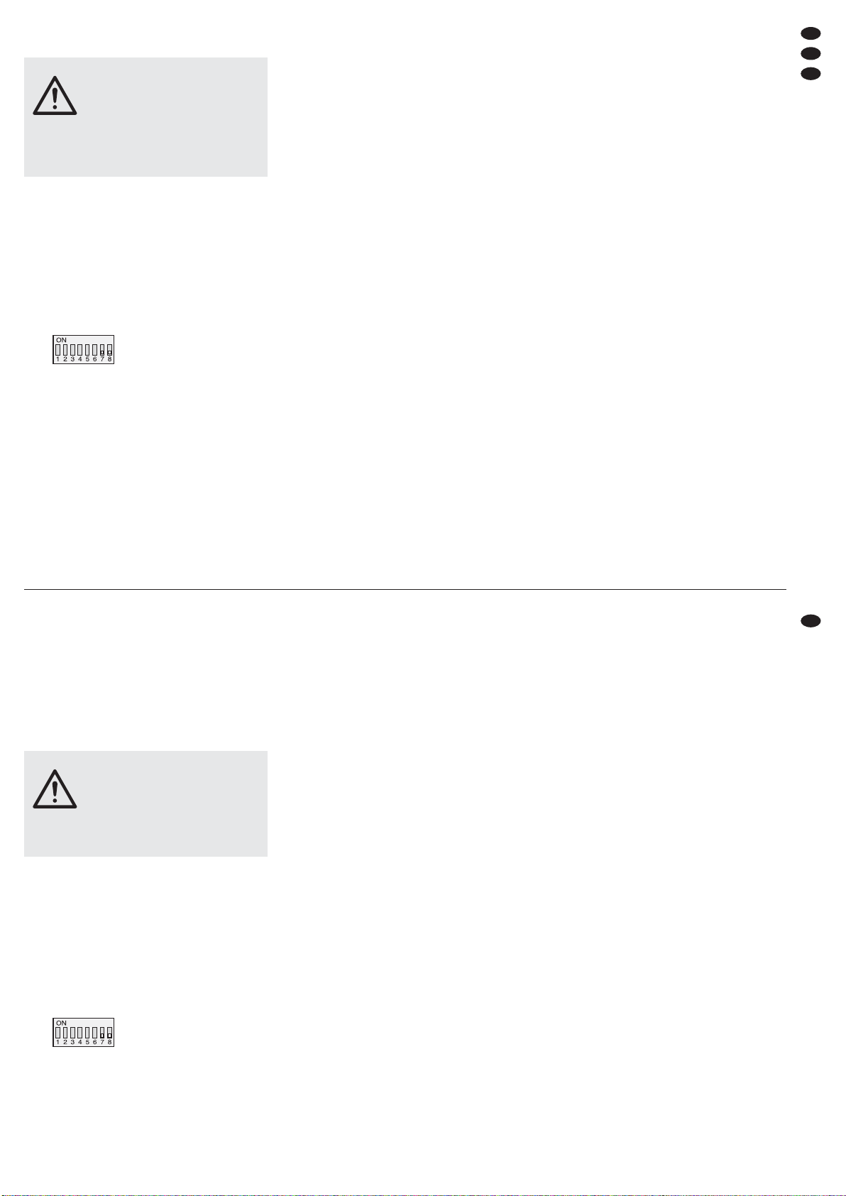
haben. Um die so entstandene Masseschleife aufzutrennen, die DIP-Schalter Nr. 7 und Nr. 8 (9) von
der oberen in die untere Position stellen:
Schalterkonstellation
Groundlift
7 Schutzschaltungen
Die Schutzschaltungen sollen Beschädigungen der
Lautsprecher und des Verstärkers verhindern. Der
eingebaute Pegelbegrenzer (Limiter) regelt das Eingangssignal zurück, wenn der Grenzpegel am
Ausgang erreicht wird. Dadurch lassen sich bei
Übersteuerung des Verstärkers Verzerrungen ver mei den, die die Lautsprecher schädigen könnten. Ist
der Begrenzer aktiv, leuchtet die LIMITER-LED (2, 4)
des entsprechenden Kanals.
Durch eine zusätzliche Schutzschaltung werden
die Lautsprecher vom Ausgang des betroffenen
Kanals getrennt. Ist sie aktiv, leuchtet die entsprechende rote PROTECT-LED (2, 4):
1. für kurze Zeit nach dem Einschalten (Einschalt-
verzögerung)
2. bei Überlastung/Überhitzung (auch z.B. durch
Kurzschluss am Ausgang oder Überschreitung
der zulässigen Ausgangsleistung im 2-Ω-Stereo-/
Parallelbetrieb oder 4-Ω-Brückenbetrieb)
3. wenn eine Gleichspannung am Ausgang auftritt
Im normalen Betrieb wird im Display (3) die Tempe-
ratur an den Leistungstransistoren für beide Kanäle
getrennt angezeigt. Bei höheren Temperaturen
sorgt die Lüfterregelung dafür, dass der Lüfter des
betroffenen Kanals mit einer höheren Geschwindigkeit läuft.
Bei einem Fehler, wie z. B. einem Kurzschluss an
einem Ausgang, wechselt (zusätzlich zu dem
Leuchten der PROTECT-LED des betroffenen
Kanals) die Anzeige auf „SHORT CIR.PROT, OVER-
LOAD&FAULT
“.
In diesem Fall oder wenn eine PROTECT-LED
nach dem Einschalten nicht erlischt oder wenn der
Schutzschalter (15) ausgelöst hat, muss der Verstärker ausgeschaltet und die Fehlerursache behoben werden. Wenn erforderlich, den Schutzschalter
durch Hineindrücken wieder zurücksetzen.
VORSICHT Stellen Sie die Lautstärke am Ver-
stärker nie sehr hoch ein. Hohe Lautstärken können auf Dauer das Gehör
schädigen! Das Ohr gewöhnt sich an
große Lautstärken und empfindet sie
nach einiger Zeit als nicht mehr so
hoch. Darum eine hohe Lautstärke
nach der Gewöhnung nicht weiter er höhen.
6.4 Level adjustment
Adjust the output of the mixer or preamplifier to its
rated level (0 dB) or the maximum undistorted output
signal. Turn up the controls (1 and 5) so far until the
maximum desired volume is reached. The LEDs
“-25 dB”, “-20 dB”, and “-15 dB” (2, 4) show the
adjusted input level. If the red LEDs LIMITER light
up, the limiter circuit is active and prevents overload
of the amplifier. In this case slightly turn back the
controls.
6.5 Groundlift switch
If an interfering hum noise can be heard without a
music signal, a ground loop may be the reason for
this. Ground loops may occur if two units have contact both via the signal ground and via the earthed
conductor of the power supply or a conductive connection of the housings in the rack. To separate the
ground loop thus occurring, set the DIP switches No.
7 and No. 8 (9) from the upper position to the lower
position.
switch configuration
Groundlift
7 Protective Circuits
The protective circuits are provided to prevent damage to the speakers and to the amplifier. The integrated level limiter reduces the input signal when the
limit level at the output is reached. Thus, in case of
overload of the amplifier, distortions can be prevented which might damage the speakers. If the limiter is active, the LED LIMITER (2, 4) of the corresponding channel lights up.
Due to an additional protective circuit the speakers are separated from the output of the channel
concerned. If it is active, the corresponding red LED
PROTECT (2, 4) lights up:
1.
for a short time after switching-on (switch-on delay)
2. in case of overload/overheating (e.g. also by
short circuit at the output or when exceeding the
admissible output power in 2 Ω stereo/parallel
operation or 4 Ω bridge operation)
3. if a DC voltage occurs at the output
During normal operation the temperature at the
power transistors is shown on the display (3) separately for both channels. With higher temperatures
the fan control ensures that the fan of the channel
concerned runs at a higher speed.
In case of a defect, e. g. a short circuit at an output, the display changes to “
SHORT CIR.PROT,
OVERLOAD&FAULT
” (in addition, the LED PROTECT
of the channel concerned lights up).
In this case, or if the LED PROTECT is not extinguished after switching-on, or if the protective switch
(15) has been released, the amplifier must be
switched off and the cause for the defect must be
eliminated. If required, reset the protective switch by
pressing it down.
CAUTION Never adjust the amplifier to a very
high volume. Permanent high volumes may damage your hearing! The
human ear will get accustomed to
high volumes which do not seem to
be that high after some time. Therefore, do not further increase a high
volume after getting used to it.
7
GB
CH
D
A
Page 8
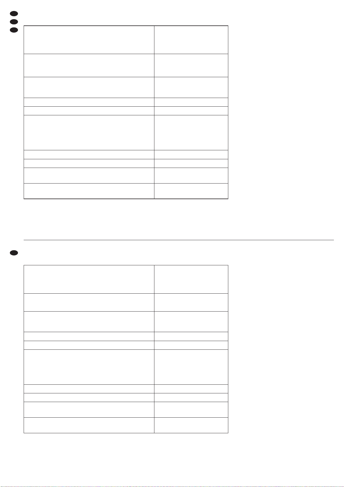
8 Technische Daten
Änderungen vorbehalten.
8 Specifications
Subject to technical modification.
8
D
A
CH
GB
All rights reserved by MONACOR®INTERNATIONAL GmbH & Co. KG. No part of this instruction manual
may be reproduced in any form or by any means for any commercial use.
Diese Bedienungsanleitung ist urheberrechtlich für MONACOR
®
INTERNATIONAL GmbH & Co. KG
geschützt. Eine Reproduktion für eigene kommerzielle Zwecke – auch auszugsweise – ist untersagt.
Sinus-Ausgangsleistung (Nennleistung)
(1 kHz, 0,1 % THD+N)
Stereo, Parallel an 4 Ω
Stereo, Parallel an 8 Ω
Brückenbetrieb an 8 Ω
2 × 1100 W
2 × 700 W
2000 W
Maximal zulässige Sinus-Ausgangsleistung
bei geringerer Lastimpedanz
Stereo, Parallel an 2 Ω
Brückenbetrieb an 4 Ω
2 × 750 W
1500 W
Eingangsempfindlichkeit für
Nennleistung an 8 Ω
Eingangsimpedanz sym./ asym.
1V
20 kΩ/10 kΩ
Frequenzbereich bei 1 W an 8 Ω 20 – 20 000 Hz (±0,3 dB)
Hochpassfilter/ Tiefpassfilter 120 Hz (-6 dB), 24 dB/ Oktave
Dämpfungsfaktor an 8 Ω
Klirrfaktor*
Kanaltrennung*
Störabstand bei Nennleistung an 8 Ω
*20 Hz – 20 kHz bei Nennleistung an 8Ω
> 300
< 0,1 %
> 60 dB
> 100 dB
Ausgangsschaltung Class H
Einsatztemperatur 0 – 40 °C
Stromversorgung
max. Leistungsaufnahme
230 V~ / 50 Hz
3600 VA
Abmessungen (B × H × T)
Gewicht
482 × 88 × 479 mm, 2 HE
23 kg
RMS output power (rated power)
(1 kHz, 0,1 % THD+N)
Stereo, parallel at 4 Ω
Stereo, parallel at 8 Ω
Bridge mode at 8 Ω
2 × 1100 W
2 × 700 W
2000 W
Maximum admissible RMS output power at lower load impedance
Stereo, parallel at 2 Ω
Bridge mode at 4 Ω
2 × 750 W
1500 W
Input sensitivity for
rated power at 8 Ω
Input impedance bal./ unbal.
1V
20 kΩ/10 kΩ
Frequency range with 1 W at 8 Ω 20 – 20 000 Hz (±0.3 dB)
High pass filter/ low pass filter 120 Hz (-6 dB), 24 dB/ octave
Attenuation factor at 8 Ω
THD*
Channel separation*
S/ N ratio with rated power at 8Ω
*20 Hz – 20 kHz with rated power at 8Ω
> 300
< 0.1 %
> 60 dB
> 100 dB
Output circuit class H
Ambient temperature 0 – 40 °C
Power supply
Max. power consumption
230 V~ / 50 Hz
3600 VA
Dimensions (W × H × D)
Weight
482 × 88 × 479 mm, 2 RS
23 kg
Page 9
Vous trouverez sur la page 3, dépliable, les éléments et branchements décrits.
1 Eléments et branchements
1.1 Face avant
1 Potentiomètre de réglage de volume pour le
canal gauche L-CH
2 LEDs dʼétat pour le canal gauche :
PROTECT : brille lorsque le circuit de protection
est activé (la liaison avec les haut-parleurs est
coupée) :
1. Après lʼallumage pendant une brève période
2. en cas de surcharge/ surchauffe (par exemple
en cas de court-circuit en sortie)
3. en cas de présence de tension continue en
sortie
LIMITER : brille lorsque le signal dʼentrée est trop
élevé et est limité par le limiteur
ACTIVE : brille comme témoin de fonctionnement
-
25 dB, -20 dB, -15 dB indiquent le niveau
dʼentrée
3 Affichage LCD pour le mode de fonctionnement
et les températures
4 LEDs dʼétat pour le canal droit (
point 2)
5 Potentiomètre de réglage de volume pour le
canal droit R-CH
6 Interrupteur Marche/Arrêt POWER
1.2 Face arrière
7 Entrées symétriques, prises XLR pour le canal
gauche (L-CH) et le canal droit (R-CH)
8 Sorties XLR pour repiquage pour diriger les
signaux dʼentrée, par exemple vers un autre
amplificateur
9 Interrupteurs DIP pour sélectionner le mode de
fonctionnement et séparer la masse du signal et
la masse du boîtier :
mode de fonctionnement
STEREO
mode de fonctionnement
PARALLEL
mode de fonctionnement
BRIDGE
masse du signal reliée à la
masse du boîtier
masse du signal et masse du
boîtier séparées (groundlift)
10 Interrupteur FILTER avec trois positions :
SUBWOOFER : filtre passe-bas avec
-
6 dB à
120 Hz
SATELLITE : filtre passe-haut avec -6 dB à 120 Hz
FULLRANGE : aucun filtre
11 Sortie haut-parleur, prise Speakon
®
, selon la
configuration de la fiche pour le canal gauche, le
canal droit ou le mode bridgé
12 Sortie haut-parleur, prise Speakon
®
pour le canal
droit
13 Sorties haut-parleurs, borniers à vis
14 Prise secteur PowerCon
®
à relier à une prise
secteur 230 V~/50 Hz avec contact de protection, p. ex. via le cordon secteur AAC-115P.
Important : la connexion PowerCon
®
ne doit pas
être reliée ou déconnectée si elle est
porteuse de tension ou de charge
(éteignez préalablement lʼappareil).
15 Interrupteur de protection pour la protection de
lʼappareil : pour réinitialiser lʼinterrupteur déclenché, enfoncez le bouton.
2 Conseils de sécurité et dʼutilisation
Lʼappareil répond à toutes les directives nécessaires
de lʼUnion européenne et porte donc le symbole .
Respectez scrupuleusement les points suivants :
G
Lʼappareil nʼest conçu que pour une utilisation en
intérieur. Protégez-le des éclaboussures, de tout
type de projections dʼeau, dʼune humidité dʼair élevée et de la chaleur (température ambiante admissible 0 – 40 °C).
G
En aucun cas, vous ne devez pas poser dʼobjet
contenant du liquide ou un verre sur lʼappareil.
G
La chaleur dégagée par lʼappareil doit être évacuée par une circulation dʼair correcte. Nʼobstruez
pas les ouïes de ventilation du boîtier.
G
Ne faites pas fonctionner lʼappareil et débranchez
le cordon secteur immédiatement dans les cas
suivants :
1. lʼappareil ou le cordon secteur présentent des
dommages visibles.
2. après une chute ou accident similaire, vous
avez un doute sur lʼétat de lʼappareil.
3. des dysfonctionnements apparaissent.
Dans tous les cas, les dommages doivent être
réparés par un technicien spécialisé.
G
Ne débranchez jamais lʼappareil en tirant sur le
cordon secteur ; retirez toujours le cordon secteur
en tirant la fiche.
AVERTISSEMENT Lʼappareil est alimenté par une
tension dangereuse. Ne touchez jamais lʼintérieur de lʼappareil et ne faites rien tomber
dans les ouïes de ventilation
car, en cas de mauvaise manipulation, vous pouvez subir
une décharge électrique.
Pendant le fonctionnement, une tension dangereuse est présente aux bornes haut-parleurs. Les
branchements ne doivent être effectués ou modifiés que lorsque lʼappareil est éteint.
A pagina 3, se aperta completamente, vedrete
sempre gli elementi di comando e i collegamenti
descritti.
1 Elementi di comando
e collegamenti
1.1 Pannello frontale
1 Regolatore volume per il canale sinistro L-CH
2 LED di stato per il canale sinistro:
PROTECT è acceso con il circuito di protezione
attivato (il collegamento con gli altoparlanti è
staccato):
1. per un breve tempo dopo lʼaccensione
2. in caso di sovraccarico/surriscaldamento
(p. es. anche in seguito a cortocircuito
allʼuscita)
3. in caso di tensione continua allʼuscita
LIMITER è acceso se il segnale dʼingresso è
troppo forte e se viene limitato dal limiter
ACTIVE è acceso come spia di funzionamento
-
25 dB, -20 dB, -15 dB indicano il livello allʼin-
gresso
3 Display a LC per il modo di funzionamento e le
temperature
4 LED di stato per il canale destro (
punto 2)
5 Regolatore volume per il canale destro R-CH
6 Interruttore on/off POWER
1.2 Lato posteriore
7 Ingressi simmetrici come prese XLR per i canali
sinistro (L-CH) e destro (R-CH)
8 Uscita XLR passanti per passare i segnali dʼin-
gresso p. es. ad un amplificatore supplementare
9 DIP-switch per la scelta del modo di funziona-
mento e per la separazione fra massa dei segnali
e del contenitore:
Modo di funzionamento
STEREO
Modo di funzionamento
PARALLEL
Modo di funzionamento
BRIDGE
Massa dei segnali collegata
con la massa del contenitore
Massa dei segnali separata
dalla massa del contenitore
(groundlift)
10 Commutatore FILTER con le tre posizioni
SUBWOOFER: filtro passa-basso a
-
6 dB con
120 Hz
SATELLITE: filtro passa-alto a
-
6 dB con 120 Hz
FULLRANGE: nessun filtro
11 Uscita altoparlanti come presa Speakon
®
, a
seconda dei contatti, per il canale sinistro, per il
canale destro o per il funzionamento a ponte
12 Uscita altoparlanti come presa Speakon
®
per il
canale destro
13 Uscita altoparlanti come morsetti a vite
14 Presa PowerCon
®
per il collegamento con una
presa di rete (230 V~/50 Hz) con conduttore di
protezione, p. es. tramite il cavo rete AAC-115P
Importante: La connessione PowerCon
®
non
deve essere collegata o separata
sotto tensione o sotto carico (spegnere prima lʼapparecchio!)
15 Interruttore automatico di protezione per lʼappa-
recchio; per resettare lʼinterruttore attivato, premere il pulsante
2 Avvertenze di sicurezza
Questʼapparecchio è conforme a tutte le direttive
rilevanti dellʼUE e pertanto porta la sigla .
Si devono osservare assolutamente anche i seguenti punti:
G
Usare lʼapparecchio solo allʼinterno di locali e proteggerlo dallʼacqua gocciolante e dagli spruzzi
dʼacqua, da alta umidità dellʼaria e dal calore (temperatura dʼimpiego ammessa fra 0 e 40 °C).
G
Non depositare sullʼapparecchio dei contenitori
riempiti di liquidi, p. es. bicchieri.
G
Devʼessere garantita la libera circolazione dellʼaria
per dissipare il calore che viene prodotto allʼinterno dellʼapparecchio. Non coprire in nessun
modo le fessure di aerazione.
G
Non mettere in funzione lʼapparecchio e staccare
subito la spina rete se:
1. lʼapparecchio o il cavo rete presentano dei
danni visibili;
2. dopo una caduta o dopo eventi simili sussiste il
sospetto di un difetto;
3. lʼapparecchio non funziona correttamente.
Per la riparazione rivolgersi sempre ad unʼofficina
competente.
G
Staccare il cavo rete afferrando la spina, senza
tirare il cavo.
AVVERTIMENTO
Lʼapparecchio funziona con
pericolosa tensione di rete. Non
intervenire mai personalmente
al suo interno e non inserire
niente nelle fessure di aerazione! Esiste il pericolo di una
scarica elettrica.
Durante il funzionamento, ai contatti degli altoparlanti è presente una tensione pericolosa. Effettuare
o modificare tutti i collegamenti solo con lʼapparecchio spento.
9
I
F
B
CH
Page 10

G
Pour le nettoyage, utilisez un chiffon sec et doux,
en aucun cas de produits chimiques ou dʼeau.
G
Nous déclinons toute responsabilité en cas de
dommages corporels ou matériels résultants si
lʼappareil est utilisé dans un but autre que celui pour
lequel il a été conçu, sʼil nʼest pas correctement
branché, utilisé ou réparé par une personne habilitée ; en outre, la garantie deviendrait caduque.
3 Possibilités dʼutilisation
Cet amplificateur professionnel stéréo est spécialement conçu pour une utilisation sur scène et en discothèque. Il peut fonctionner en mode stéréo, mono
parallèle ou mono bridgé. Grâce au circuit de sortie
de classe H, il fonctionne plus efficacement que des
amplificateurs standards de technologie classe AB.
Grâce au filtre commutable, lʼamplificateur peut être
utilisé uniquement pour les subwoofers ou uniquement pour la plage de fréquences au-delà de 120 Hz.
De multiples circuits de protection protègent lʼamplificateur et les haut-parleurs reliés. Deux ventilateurs
puissants, contrôlés par la température, délivrent le
refroidissement suffisant de lʼamplificateur.
4 Possibilités de positionnement
Lʼamplificateur est conçu pour une installation en
rack (482 mm/19″) mais peut être également posé
directement sur une table. Dans tous les cas, lʼair
doit pouvoir passer sans encombre via les ouïes
dʼaération pour assurer un refroidissement suffisant.
4.1 Installation en rack
Pour un montage en rack, deux unités = 89 mm sont
nécessaires. Lʼair chaud dégagé par lʼappareil à lʼar-
rière doit pouvoir être évacué du rack. Sinon, il y a
accumulation de chaleur dans le rack, ce qui peut
endommager non seulement lʼamplificateur mais
dʼautres appareils placés dans le rack. En cas de
dégagement insuffisant de la chaleur, installez un
ventilateur dans le rack.
Afin que le rack ne se renverse pas, vous devez
placer lʼamplificateur dans la partie inférieure du
rack. Pour une fixation solide, la plaque avant seule
nʼest pas suffisante, lʼamplificateur doit en plus, être
maintenu par des rails latéraux ou une plaque inférieure.
5 Branchements de lʼamplificateur
Les branchements ne doivent être effectués que
lorsque lʼamplificateur est éteint !
1) Reliez la sortie dʼun préamplificateur ou dʼune
table de mixage aux prises XLR INPUTS (7). Les
prises sont configurées pour des signaux symé-
triques ; la configuration est présentée sur le
schéma 2. Pour brancher des sources avec
signaux asymétriques, utilisez un adaptateur où
les contacts XLR 1 et 3 sont bridgés (par exem-
ple adaptateur MCA-15/2 de “img Stage Line” :
fiche jack 6,35 femelle 2 pôles sur XLR mâle).
Le signal dʼentrée devrait avoir un niveau
Ligne. Pour une puissance nominale de lʼamplificateur, un signal dʼentrée doit être de 1 V au
moins.
Pour le mode bridgé ou parallèle, reliez uniquement lʼentrée du canal gauche L-CH.
Via les prises pour repiquage (8) directement
reliées à la prise dʼentrée correspondante (7), le
signal peut être dirigé par exemple vers un amplificateur supplémentaire.
2) La puissance de sortie la plus importante est
atteinte en mode stéréo et en mode parallèle
avec des haut-parleurs 4 Ω (impédance de
charge minimale autorisée à pleine puissance). Il
est également possible de brancher des hautparleurs 8 Ω, ce qui diminue un peu la puissance
de sortie. En mode bridgé, la puissance de sortie
la plus grande est atteinte avec un haut-parleur
8 Ω (impédance de charge minimale autorisée à
pleine puissance en mode bridgé). La puissance
nominale (P
MIN) des haut-parleurs est indiquée
dans le tableau schéma 3.
Tant qu'en mode stéréo ou parallèle, la puissance RMS de sortie de 750 W par canal n'est
pas dépassée, le fonctionnement avec des
charges 2 Ω est également possible. Un fonctionnement bridgé sous une charge de 4 Ω est possible jusqu'à une puissance de sortie RMS de
1500 W.
Reliez les haut-parleurs aux prises Speakon
®
(11, 12), voir schéma 2 pour la configuration, ou
aux bornes (13).
Après avoir inséré une fiche Speakon
®
, tournez-la dans la prise vers la droite jusquʼà ce
quʼelle sʼenclenche. Pour la retirer plus tard, retirez le verrou sur la fiche et tournez la fiche vers la
gauche.
Si vous utilisez les bornes à vis, assurez-vous
que les extrémités de câble ne soient pas trop
dénudées et quʼaucun fil nu ne sorte (risque de
contact et de court-circuit).
Lorsque vous branchez les haut-parleurs, veillez à respecter la même polarité de tous les hautparleurs.
La prise Speakon
®
de la sortie L-CH (11) est
en plus configurée avec les signaux de la sortie
droite R-CH : il est ainsi possible de relier les
deux haut-parleurs à cette prise via un câble
4 pôles.
Pour le mode bridgé, reliez le contact plus du
haut-parleur à la borne plus (13) de la sortie
gauche L-CH et le pôle moins du haut-parleur à
la borne plus de la sortie droite R-CH [voir
schéma 2]. (La borne plus de la sortie droite
devient, par lʼinversion du signal en mode bridgé,
la borne moins pour le haut-parleur). Le haut-par-
Lorsque lʼappareil est définitivement retiré
du service, vous devez le déposer dans
une usine de recyclage de proximité pour
contribuer à son élimination non polluante.
G
Per la pulizia usare solo un panno morbido,
asciutto; non impiegare in nessun caso prodotti
chimici o acqua.
G
Nel caso dʼuso improprio, dʼimpiego scorretto, di
collegamenti sbagliati o di riparazione non a
regola dʼarte dellʼapparecchio, non si assume nessuna responsabilità per eventuali danni consequenziali a persone o a cose e non si assume nessuna garanzia per lʼapparecchio.
3 Possibilità dʼimpiego
Questo amplificatore PA stereo è stato realizzato
specialmente per lʼimpiego sul palcoscenico e in
discoteca. Può essere usato con funzionamento stereo, mono parallelo o mono a ponte. Con il suo circuito dʼuscita Class H funziona con maggiore efficienza rispetto agli amplificatori tradizionali con
tecnologia Class AB. Grazie ad un filtro commutabile, lʼamplificatore può essere utilizzato anche solo
per subwoofer oppure solo per le frequenze oltre
120 Hz. Vasti circuiti di protezione proteggono lʼamplificatore e gli altoparlanti collegati. Due ventilatori
potenti, termoregolati, provvedono al raffreddamento necessario dellʼamplificatore.
4 Possibilità di collocamento
Lʼamplificatore è previsto per lʼinserimento in un rack
(482 mm/19″), ma può essere usato anche come
apparecchio da tavolo. In ogni caso deve essere
possibile che lʼaria possa circolare liberamente
attraverso tutte le fessure di aerazione per garantire
un raffreddamento sufficiente.
4.1 Montaggio nel rack
Per il montaggio in un rack sono richieste due unità
di altezza RS (= 89 mm). Lʼaria riscaldata emessa
sul retro dellʼamplificatore deve potere uscire dal
rack. Altrimenti si può provocare un accumulo di
calore nel rack con possibili danni non solo allʼamplificatore ma anche ad altri apparecchi presenti nel
rack. Se la dissipazione del calore è insufficiente
occorre montare un ventilatore nel rack.
Per evitare che il rack risulti squilibrato con troppi
pesi in alto, è necessario che lʼamplificatore venga
montato nella parte bassa del rack. Per un fissaggio
sicuro non è sufficiente il pannello frontale. Lʼapparecchio deve essere fissato anche sul retro oppure
deve essere appoggiato su guide laterali oppure su
un piano.
5 Collegare lʼamplificatore
Tutti i collegamenti devono essere effettuati o modificati solo con lʼapparecchio spento!
1) Collegare lʼuscita di un preamplificatore o di un
mixer con le prese XLR INPUTS (7). Entrambe le
prese sono previste per segnali simmetrici; i con-
tatti si vedono in fig. 2. Per il collegamento di sor-
genti con segnali asimmetrici usare un adattatore
nel quale i contatti XLR 1 e 3 sono ponticellati (p.
es. lʼadattatore MCA-15/2 di “img Stage Line”:
presa jack 6,3mm a 2 poli su maschio XLR).
Il segnale dʼingresso dovrebbe essere con
livello Line. Per pilotare completamente lʼamplificatore occorre un segnale dʼingresso di 1 V min.
Per il funzionamento a ponte o parallelo, collegare solo lʼingresso del canale sinistro L-CH.
Tramite le uscite passanti (8), collegate direttamente con le relative prese dʼingresso (7), è
possibile inoltrare il segnale p. es. ad un amplificatore supplementare.
2) La potenza dʼuscita maggiore si ottiene con il funzionamento stereo e parallelo se si collegano
degli altoparlanti di 4 Ω (impedenza di carico
minima ammessa in caso di pilotaggio totale). Si
possono collegare anche altoparlanti di 8 Ω il ché
riduce leggermente la potenza dʼuscita. Con il
funzionamento a ponte, la potenza maggiore si
ottiene con un altoparlante di 8 Ω (impedenza di
carico minima ammessa in caso di pilotaggio
totale con funzionamento a ponte). La potenza
nominale necessaria (P
MIN) degli altoparlanti è
indicata nella tabella fig. 3.
Finché durante il funzionamento stereo o
parallelo, la potenza efficace d'uscita di 750 W
per canale non viene superata, è possibile anche
l'uso con carichi di 2 Ω. Il funzionamento a ponte
con un carico di 4 Ω è possibile fino ad una
potenza efficace d'uscita di 1500 W.
Collegare gli altoparlanti alle prese Speakon
®
(11, 12), per i contatti del connettore vedi fig. 2,
oppure ai morsetti a vite (13).
Un connettore Speakon
®
, dopo lʼinserimento
nella presa, va girato a destra fino allo scatto. Per
sfilarlo successivamente, tirare indietro al levetta
di sicurezza sul connettore e girarlo a sinistra.
Se si usano i morsetti a vite, fare attenzione a
non deisolare troppo i terminali dei cavi per non
far sporgere dei fili nudi (pericolo per il contatto
con le mani e di cortocircuito).
Collegando gli altoparlanti, far attenzione allʼidentica polarità di tutti gli altoparlanti.
Sulla presa Speakon
®
dellʼuscita L-CH (11)
sono presenti in più i segnali dellʼuscita destra
R-CH; così è possibile collegare entrambi agli
altoparlanti con questa presa per mezzo di un
cavo a quattro poli.
Per il funzionamento a ponte collegare il
contatto positivo dellʼaltoparlante con il morsetto
positivo (13) dellʼuscita sinistra L-CH, e il contatto
negativo dellʼaltoparlante con il morsetto positivo
dellʼuscita destra R-CH [vedi fig. 2]. (Il morsetto
positivo dellʼuscita destra, per via dellʼinversione
dei segnali nel funzionamento a ponte, diventa il
contatto negativo per lʼaltoparlante.) In alterna-
Se si desidera eliminare lʼapparecchio definitivamente, consegnarlo per lo smaltimento ad unʼistituzione locale per il riciclaggio.
10
F
B
CH
I
Page 11
leur peut, à la place, être relié à la prise Speakon®L-CH (11). Reliez selon le schéma 2, la
borne plus du haut-parleur au contact 1+ et la
borne moins au contact 2+ de la fiche.
Dans le tableau du schéma 3, sont également
présentées les possibilités de branchement
pour plusieurs haut-parleurs à une sortie. La
puissance nominale ( P
MIN) que chaque haut-par-
leur doit au moins avoir pour une impédance donnée (Z) est indiquée dans chaque cas. Si plusieurs haut-parleurs sont branchés ensemble,
veillez à respecter le branchement correct des
bornes plus et moins.
Important : l'impédance totale à chaque sortie
ne doit pas être inférieure à pleine puissance en
mode stéréo et parallèle à 4 Ω et en mode bridgé
à 8 Ω.
Tant qu'en mode stéréo ou parallèle, la puissance RMS de sortie de 750 W par canal n'est
pas dépassée, le fonctionnement avec des
charges 2 Ω est également possible. Un fonctionnement bridgé sous une charge de 4 Ω est possible jusqu'à une puissance de sortie RMS de
1500 W.
3) Lʼappareil est livré sans cordon secteur. Utilisez
un cordon secteur avec fiche PowerCon
®
et une
fiche secteur avec contact de protection, par
exemple AAC-115P de “img Stage Line”.
Reliez tout dʼabord la fiche PowerCon
®
à la
prise secteur (14), tournez vers la droite jusquʼà
ce quʼelle sʼenclenche puis reliez la fiche secteur
à une prise secteur (230 V~/50 Hz). Pour débrancher lʼappareil, retirez tout dʼabord la prise puis
tirez vers lʼarrière le levier de verrouillage pour
retirer la fiche PowerCon®et tournez la fiche vers
la gauche.
Assurez-vous que le circuit de courant auquel
lʼappareil est relié, ait un fusible en conséquence
(16 A).
6 Utilisation
6.1 Sélection du mode de fonctionnement
Avec les interrupteurs DIP MODE N°1 à 6 (9), sélectionnez le mode de fonctionnement voulu :
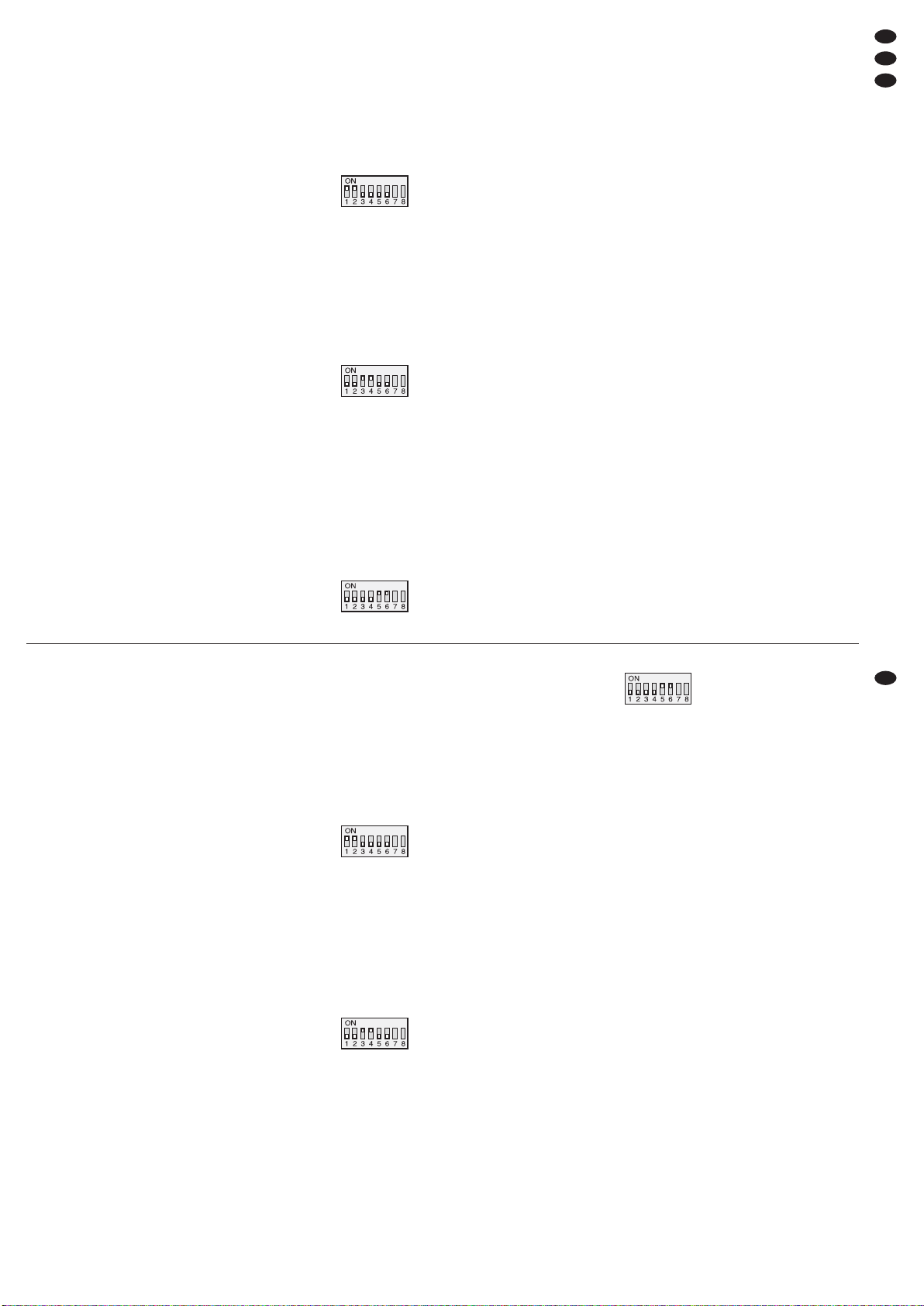
Mode stéréo – “MODE STEREO”
En mode stéréo, les deux canaux fonctionnent, indé-
pendamment lʼun de lʼautre.
Configuration interrupteu
STEREO
Mode parallèle – “MODE PARALLEL”
Si par exemple deux pièces doivent être sonorisées
avec le même signal mono, et si le volume doit être
réglable séparément, vous pouvez utiliser le mode
parallèle.
Le signal dʼentrée est en plus branché en interne
du canal gauche sur le canal droit. Un signal à lʼentrée droite est ignoré. Le réglage de volume sʼeffectue séparément pour les deux sorties.
Configuration interrupteur
PARALLEL
Mode bridgé – “
MODE BRIDGE”
Le fonctionnement bridgé (BRIDGE) permet dʼobtenir une plus grande puissance sur un haut-parleur.
Les deux canaux dʼamplificateur sont combinés en
un amplificateur mono. Le signal dʼentrée sur le canal
gauche est en plus branché au canal droit, à lʼinverse.
La tension en sortie est doublée lorsque le haut-parleur, comme décrit dans le schéma 5, est branché
pour le mode bridgé. Un signal à lʼentrée droite est
ignoré. Le réglage de volume sʼeffectue en commun
pour les deux sorties avec le réglage gauche (1).
Configuration interrupteur
BRIDGE
6.2 Filtre
Le filtre intégré peut être utilisé comme filtre de fréquences pour des systèmes haut-parleurs 2 voies
(subwoofer/satellite). Avec lʼinterrupteur FILTER
(10), sélectionnez la fonction correspondant au
haut-parleur relié.
position SUBWOOFER :
filtre passe-bas avec
-
6 dB à 120 Hz
pour haut-parleurs de grave
position SATELLITE :
filtre passe-haut avec
-
6 dB à 120 Hz
pour haut-parleurs de médium aigu
position FULLRANGE :
aucun filtre pour les haut-parleurs passe bande
6.3 Marche/Arrêt
Pour éviter les bruits forts de commutation, allumez
toujours lʼétage final dʼune installation dʼamplificateur après tous les autres appareils et éteignez-le en
premier après lʼutilisation. Avant la première mise en
service, tournez les réglages (1 et 5) vers la gauche
sur “-80 dB”.
Allumez lʼamplificateur avec lʼinterrupteur
POWER (6). Les LEDs ACTIVE (2, 4) brillent et servent de témoin de fonctionnement, lʼaffichage (3)
indique le mode de fonctionnement retenu. Après
lʼallumage, les LEDs PROTECT rouges (2, 4) brillent
brièvement. Pendant ce temps, la temporisation dʼallumage pour protéger les haut-parleurs est activée.
6.4 Réglage de niveau
Réglez la sortie de la table de mixage ou du préamplificateur sur son niveau nominal (0 dB) ou sur le
signal de sortie le plus élevé non distordu. Tournez
les réglages (1 et 5) jusquʼà atteindre le volume
maximal souhaité. Les LEDs “-25 dB”, “-20 dB”,
“-15 dB” (2, 4) indiquent le niveau dʼentrée réglé. Si
les LEDs rouges LIMITER brillent, le circuit de limitation est activé et empêche toute surcharge de
tiva, lʼaltoparlante può essere collegato anche
con la presa Speakon®L-CH (11). In questo
caso, come si vede in fig. 2, collegare il morsetto
positivo dellʼaltoparlante con il contatto 1+ e il
morsetto negativo con il contatto 2+ del connettore.
La tabella fig. 3 illustra anche delle possibilità
di collegamento per più altoparlanti con
unʼuscita. Per ogni caso, è indicato quale potenza
nominale minima (P
MIN) è richiesta per il singolo
altoparlante rispetto alla relativa impedenza (Z).
Assemblando più altoparlanti, si deve fare molta
attenzione al corretto collegamento dei contatti
positivi e negativi.
Importante: In caso di pilotaggio totale, l'impedenza totale per ogni uscita non deve essere
inferiore a 4 Ω nel funzionamento stereo e parallelo e a 8 Ω nel funzionamento a ponte!
Finché durante il funzionamento stereo o
parallelo, la potenza efficace d'uscita di 750 W
per canale non viene superata, è possibile anche
l'uso con carichi di 2 Ω. Il funzionamento a ponte
con un carico di 4 Ω è possibile fino ad una
potenza efficace d'uscita di 1500 W.
3) Lʻapparecchio viene consegnato senza cavo
rete. Per il collegamento usare un cavo con connettore PowerCon
®
e con spina con conduttore di
protezione (p. es. AAC-115P di “img Stage Line”).
Per prima cosa inserire il connettore Power-
Con
®
nella presa (14) e girarlo a destro fino allo
scatto e quindi inserire la spina in una presa di
rete (230 V~/50 Hz). Per separare lʼapparecchio
dalla rete staccare prima la spina dalla presa di
rete e per sfilare il connettore PowerCon®tirare
indietro la sua levetta di sicurezza e girare il connettore a sinistra.
Verificare che il circuito, nel quale è collegato
lʼapparecchio, si sufficientemente protetto (16 A).
6 Funzionamento
6.1 Scegliere il modo di funzionamento
Con i dip-switch MODE n. 1 –6 (9) scegliere il modo
richiesto:
Funzionamento stereo –“
MODE STEREO”
Con il funzionamento stereo, entrambi i canali funzionano indipendentemente fra di loro.
Posizione degli switch
STEREO
Funzionamento parallelo –“
MODE PARALLEL”
Se, per esempio, è richiesta la sonorizzazione di due
ambienti con un unico segnale mono, mentre il
volume deve essere regolabile singolarmente, è
consigliabile il funzionamento parallelo.
Internamente, il segnale dʼingresso viene portato
dal canale sinistro anche sul canale destro. Un
segnale allʼingresso destro viene ignorato. La regolazione del volume avviene separatamente per i due
canali.
Posizione degli switch
PARALLEL
Funzionamento a ponte –“
MODE BRIDGE”
Il funzionamento a ponte (BRIDGE) serve per ottenere una maggiore potenza con un altoparlante.
In questo caso, i due canali dellʼamplificatore
vengono combinati per creare un amplificatore
mono: in più, il segnale dʼingresso del canale sinistro
viene invertito e portato sul canale destro. In questo
modo, la tensione allʼuscita raddoppia se lʼaltoparlante è collegato, come descritto nel capitolo 5, per il
funzionamento a ponte. Un segnale allʼingresso
destro viene ignorato. La regolazione del volume
avviene in comune per i due canali per mezzo del
regolatore sinistro (1).
Posizione degli switch
BRIDGE
6.2 Filtro
Il filtro integrato può essere usato come filtro di frequenza per altoparlanti a 2 vie (subwoofer/ satellite).
Con il commutatore FILTER (10), scegliere la funzione che corrisponde allʼaltoparlante collegato.
Posizione SUBWOOFER:
filtro passa-basso a
-
6 dB con 120 Hz
per woofer
Posizione SATELLITE:
filtro passa-alto a
-
6 dB con 120 Hz
per midrange/tweeter
Posizione FULLRANGE:
nessun filtro per altoparlante a larga banda
6.3 Accendere/spegnere
Per escludere forti rumori di commutazione, accendere lʼamplificatore finale di un impianto dʼamplificazione sempre dopo tutti gli altri apparecchi, e dopo
lʼuso spegnerlo nuovamente per primo. Prima della
prima accensione portare i regolatori (1 e 5) tutto a
sinistra, su “-80 dB”.
Accendere lʼamplificatore con lʼinterruttore
POWER (6). I LED ACTIVE (2, 4) si accendono
come spie di funzionamento e il display (3) indica il
modo di funzionamento scelto. Dopo lʼaccensione,
si accendono brevemente i LED rossi PROTECT (2,
4). Durante questo tempo è attivato il ritardo dʼinserimento per proteggere gli altoparlanti.
6.4 Regolare il livello
Regolare lʼuscita del mixer o del preamplificatore
secondo il suo livello nominale (0 dB) oppure
secondo il maggiore segnale dʼuscita non distorto.
Aprire i regolatori (1 e 5) fino al punto da raggiungere
il volume massimo richiesto. I LED “-25 dB”,
“-20 dB” e “-15 dB” (2, 4) indicano il livello dʼin-
11
I
F
B
CH
Page 12
lʼamplificateur. Dans ce cas, tournez un peu les
réglages dans lʼautre sens pour diminuer.
6.5 Interrupteur Groundlift
Si un ronflement perturbateur est audible, sans
signal de musique, un bouclage de masse peut en
être la cause. Des bouclages de masse peuvent se
créer lorsque deux appareils ont un contact soit par
la masse de signal soit par le conducteur de lʼalimentation ou une liaison conductrice des boîtiers
dans le rack. Pour séparer la boucle de masse ainsi
créée, mettez les interrupteurs DIP N° 7 et 8 (9) de
la position supérieure sur la position inférieure :
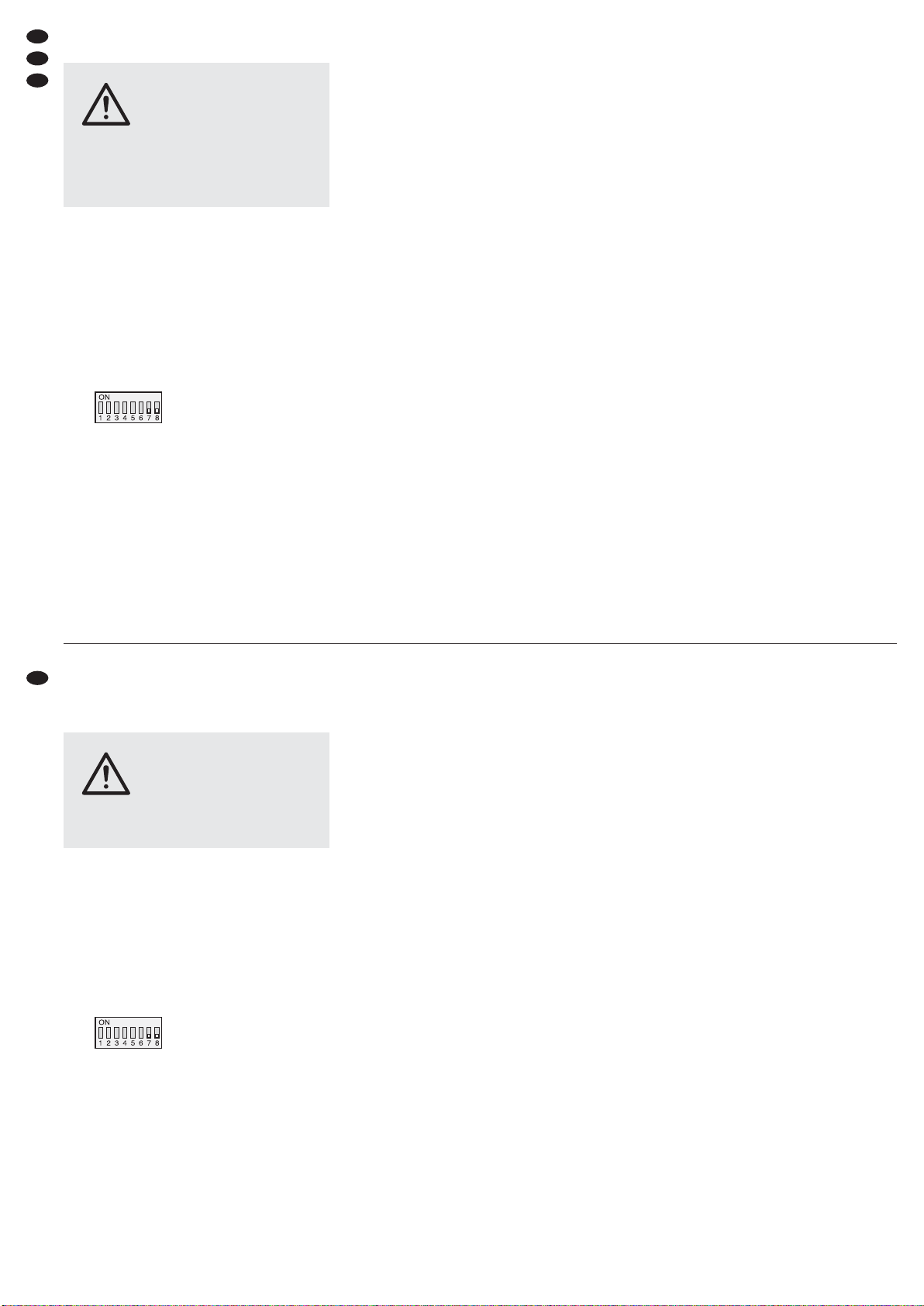
Configuration interrupteur
Groundlift
7 Circuits de protection
Les circuits de protection doivent éviter tout dommage sur les haut-parleurs et sur lʼamplificateur. Le
limiteur intégré diminue le signal dʼentrée lorsque le
niveau limite en sortie est atteint. Ainsi, en cas de
surcharge de lʼamplificateur, on peut éviter les distorsions qui peuvent endommager les haut-parleurs.
Si le limiteur est activé, la LED LIMITER (2, 4) du
canal correspondant brille.
Les haut-parleurs sont coupés de la sortie du
canal concerné par un circuit de protection supplémentaire. Sʼil est activé, la LED rouge PROTECT
(2, 4) correspondante brille :
1. brièvement après lʼallumage (temporisation dʼal-
lumage)
2. en cas de surcharge/surchauffe (par exemple en
cas de court-circuit en sortie ou de dépassement
de la puissance de sortie autorisée en mode sté-
réo/parallèle 2 Ω ou mode bridgé 4 Ω).
3. en cas de présence de tension continue en sortie
En mode normal, lʼaffichage (3) indique la tempéra-
ture au niveau des transistors de puissance pour les
deux canaux séparément. Pour des températures
plus importantes, la gestion de la ventilation assure
que le ventilateur du canal concerné fonctionne à
une vitesse plus importante.
En cas de problème, par exemple un court-circuit
à une sortie, lʼaffichage passe à “SHORT CIR.PROT,
OVERLOAD&FAULT”
(en plus la LED PROTECT du
canal concerné qui brille).
Dans ce cas, ou si une LED PROTECT ne sʼéteint
pas après lʼallumage ou si lʼinterrupteur de protection
(15) a déclenché, lʼamplificateur doit être éteint et le
problème résolu. Si besoin, réinitialisez lʼinterrupteur
de protection en appuyant sur le bouton.
PRECAUTION Ne réglez jamais le volume, sur
lʼamplificateur, de manière très
élevée. Un volume trop élevé peut,
à long terme, générer des troubles
de lʼaudition. Lʼoreille humaine
sʼhabitue à des volumes élevés et
ne les perçoit plus comme tels au
bout dʼun certain temps. Nous
vous conseillons donc de régler le
volume et de ne plus le modifier.
gresso impostato. Se si accendono i LED rossi LIMITER, significa che il circuito di limitazione è attivo
per impedire il sovrapilotaggio dellʼamplificatore. In
questo caso ridurre leggermente i regolatori.
6.5 Interruttore groundlift
Se senza un segnale di musica si avverte un ronzio
fastidioso, è possibile che la causa ne sia un anello
di terra. Tali anelli di terra si creano se due apparecchi sono in contatto, sia tramite la massa dei segnali
che tramite il conduttore di protezione dellʼalimentazione oppure tramite un altro conduttore delle casse
nel rack. Per aprire lʼanello creatosi, spostare i dipswitch n. 7 e n. 8 (9) dalla posizione superiore nella
posizione inferiore:
Posizione degli switch
Groundlift
7 Circuiti di protezione
I circuiti di protezione servono per escludere danni
agli altoparlanti e allʼamplificatore. Il limitatore integrato del livello (Limiter) riduce il segnale dʼingresso
se allʼuscita è raggiunto il livello limite. In questo
modo, in caso di sovrapilotaggio dellʼamplificatore,
si evitano delle distorsioni che potrebbero danneggiare gli altoparlanti. Se il limiter è attivo, si accende
il LED LIMITER (2, 4) del relativo canale.
Con un circuito supplementare di protezione, gli
altoparlanti vengono separati dallʼuscita del canale
interessato. Se tale circuito è attivo, si accende il
relativo LED rosso PROTECT (2, 4):
1. per un breve tempo dopo lʼaccensione (ritardo
dʼinserimento)
2. con sovraccarico/surriscaldamento (p.es. anche
per via di un cortocircuito all'uscita o del supera-
mento della potenza d'uscita ammessa nel fun-
zionamento stereo/parallelo con 2 Ω o a ponte
con 4 Ω
3. se è presente una tensione continua allʼuscita
Nel funzionamento normale, il display (3) indica la
temperatura dei transistori di potenza separatamente per i due canali. Con le temperature più alte,
la regolazione del ventilatore fa sì che il ventilatore
del canale interessato giri con velocità maggiore.
In caso di difetto, p. es. per un cortocircuito ad
unʼuscita (oltre allʼaccensione del LED PROTECT
del relativo canale) si vede anche lʼindicazione
“
SHORT CIR.PROT, OVERLOAD&FAULT”.
In questo caso, o se un LED PROTECT non si
spegne dopo lʼaccensione oppure se ha reagito lʼinterruttore automatico (15), occorre spegnere lʼamplificatore e si deve eliminare il difetto. Se necessario
riattivare lʼinterruttore automatico con un pressione
sullo stesso.
ATTENZIONE Mai tenere molto alto il volume del-
lʼamplificatore. A lungo andare, il
volume eccessivo può procurare
danni allʼudito! Lʼorecchio si abitua
agli alti volumi e dopo un certo
tempo non se ne rende più conto.
Perciò non aumentare il volume
successivamente.
12
F
B
CH
I
Page 13
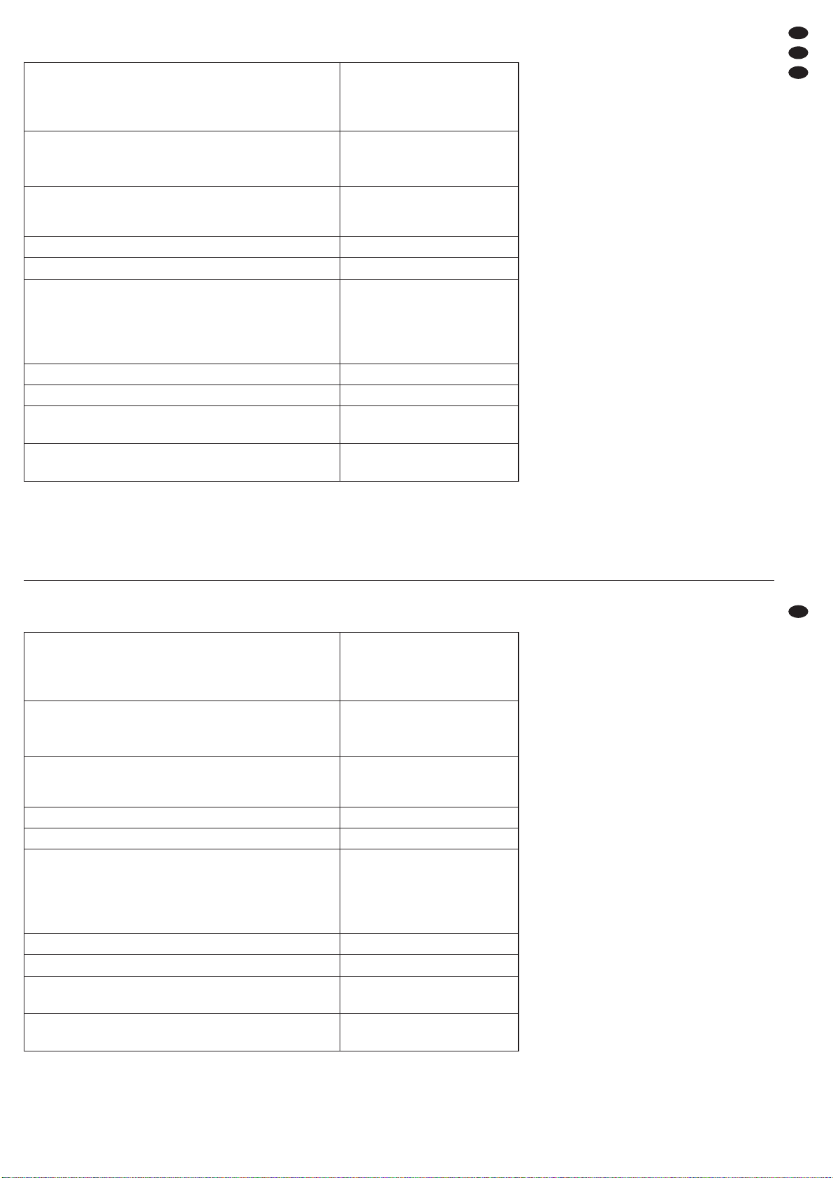
8 Caractéristiques techniques
Tout droit de modification réservé.
8 Dati tecnici
Con riserva di modifiche tecniche.
13
I
F
B
CH
Notice dʼutilisation protégée par le copyright de MONACOR®INTERNATIONAL GmbH & Co. KG. Toute
reproduction même partielle à des fins commerciales est interdite.
La MONACOR
®
INTERNATIONAL GmbH & Co. KG si riserva ogni diritto di elaborazione in qualsiasi forma
delle presenti istruzioni per lʼuso. La riproduzione – anche parziale – per propri scopi commerciali è vietata.
Puissance de sortie RMS (puissance nominale)
(1 kHz, 0,1 % THD+N)
Stéréo, parallèle sous 4 Ω
Stéréo, parallèle sous 8 Ω
Mode bridgé sous 8 Ω
2 × 1100 W
2 × 700 W
2000 W
Puissance de sortie RMS maximale autorisée
pour une impédance de charge plus faible
Stéréo, parallèle sous 2 Ω
Mode bridgé sous 4 Ω
2 × 750 W
1500 W
Sensibilité dʼentrée
pour une puissance nominale sous 8 Ω
Impédance dʼentrée sym. / asym.
1V
20 kΩ/10 kΩ
Bande passante pour 1 W sous 8 Ω 20 – 20 000 Hz (±0,3 dB)
Filtre passe-haut/filtre passe-bas 120 Hz (-6 dB), 24 dB/ octave
Facteur dʼatténuation sous 8 Ω
Taux de distorsion*
Séparation des canaux*
Rapport signal sur bruit pour une puissance nominale sous 8 Ω
*20 Hz – 20 kHz pour une puissance nominale sous 8Ω
> 300
< 0,1 %
> 60 dB
> 100 dB
Circuit de sortie Classe H
Température fonc. 0 – 40 °C
Alimentation
Consommation maximale
230 V~ / 50 Hz
3600 VA
Dimensions (L × H × P)
Poids
482 × 88 × 479 mm, 2 U
23 kg
Potenza efficace allʼuscita (potenza nominale)
(1 kHz, 0,1 % THD+N)
Stereo, parallelo con 4 Ω
Stereo, parallelo con 8 Ω
Funzionamento a ponte con 8 Ω
2 × 1100 W
2 × 700 W
2000 W
Potenza efficace d'uscita massima ammessa
con impedenza di carico ridotta
Stereo, parallelo con 2 Ω
Funzionamento a ponte con 4 Ω
2 × 750 W
1500 W
Sensibilità dellʼingresso
per potenza nominale con 8 Ω
Impedenza dellʼingresso simm./asimm.
1V
20 kΩ/10 kΩ
Gamma di frequenze a 1 W con 8 Ω 20 – 20 000 Hz (±0,3 dB)
Filtro passa-alto/passa-basso 120 Hz (-6 dB), 24 dB/ ottava
Fattore dʼattenuazione con 8 Ω
Fattore di distorsione*
Separazione canali*
Rapporto S/R con potenza nominale con 8 Ω
*20 Hz – 20 kHz con potenza nominale con 8Ω
> 300
< 0,1 %
> 60 dB
> 100 dB
Circuito dʼuscita Class H
Temperatura dʼesercizio 0 – 40 °C
Alimentazione
Potenza assorbita max.
230 V~ / 50 Hz
3600 VA
Dimensioni (l × h × p)
Peso
482 × 88 × 479 mm, 2 RS
23 kg
Page 14
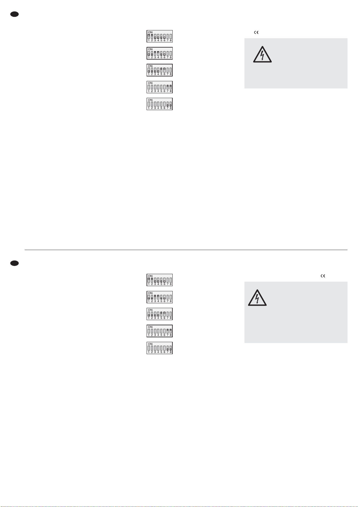
Puede encontrar todos los elementos de funcionamiento y las conexiones que se describen en
la página 3 desplegable.
1 Elementos de Funcionamiento
y Conexiones
1.1 Panel frontal
1 Control de volumen para el canal izquierdo L-CH
2 LEDs de estado para el canal izquierdo:
Se ilumina PROTECT cuando el circuito de protección está activado (la conexión a los altavoces está separada):
1. Durante unos instantes después de la conexión
2. En caso de sobrecarga/ sobrecalentamiento
(p. ej. también por un cortocircuito en la salida)
3. Si hay voltaje CC en la salida
Se ilumina LIMITER cuando la señal de entrada
es demasiado alta y limitado por el limitador
Se ilumina ACTIVE como indicación de corriente
-
25 dB, -20 dB, -15 dB muestran el nivel de
entrada
3 Visualizador LC para el modo de funcionamiento
y las temperaturas
4
LEDs de estado para el canal derecho (punto 2)
5 Control de volumen para el canal derecho R-CH
6 Interruptor POWER
1.2 Panel posterior
7 Entradas simétricas: Tomas XLR para el canal
izquierdo (L-CH) y para el canal derecho (R-CH)
8 Salidas XLR alimentadas para pasar las señales
de entrada p. ej. a un amplificador adicional
9 Interruptores DIP para seleccionar el modo de
funcionamiento y para separar la masa de señal
y la masa de la carcasa:
Modo de funcionamient
STEREO
Modo de funcionamient
PARALLEL
Modo de funcionamient
BRIDGE
Masa de señal conectada a la
masa de la carcasa
Masa de señal y masa de la
carcasa separadas (interruptor de masa = groundlift)
10 Interruptor FILTER con 3 posiciones
SUBWOOFER: Filtro pasa bajo con
-
6 dB a
120 Hz
SATELLITE: Filtro pasa alto con
-
6 dB a 120 Hz
FULLRANGE: Sin filtro
11 Salida de altavoz: Toma Speakon
®
, dependiendo de la configuración de la toma para el
canal izquierdo, el canal derecho, o para el modo
punteado
12 Salida de altavoz: Toma Speakon
®
para el canal
derecho
13 Salidas de altavoz: Terminales de tornillo
14
Toma de corriente PowerCon®para la conexión a
un enchufe (230 V~/50 Hz) con contacto protector
p. ej. mediante el cable de corriente AAC-115P
Importante: La toma PowerCon®no tiene que
conectarse ni desconectarse cuando
hay carga o corriente. (Desconecte
el aparato con antelación)
15 Interruptor de protección para el aparato; para
reajustar el interruptor liberado, pulse el botón
2 Notas de Seguridad
El aparato cumple con todas las directivas relevantes de la UE y por lo tanto está marcado con el símbolo .
Preste atención a los puntos siguientes bajo cualquier circunstancia:
G
El aparato está adecuado para su utilización sólo
en interiores. Protéjalo de goteos y salpicaduras,
elevada humedad del aire y calor (temperatura
ambiente admisible: 0 – 40 ºC).
G
No coloque ningún recipiente lleno de líquido
encima del aparato, como por ejemplo un vaso.
G
El calor generado en el interior del aparato tiene
que disiparse con la circulación del aire. Por eso
no tienen que obstruirse las rejillas de ventilación
de la carcasa.
G
No ponga el aparato en funcionamiento o desconecte inmediatamente el enchufe de la toma de
corriente si:
1. Existe algún daño visible en el aparato o en el
cable de corriente.
2. Aparece algún defecto por caída o accidente
similar.
3. No funciona correctamente.
Sólo el personal cualificado puede reparar el aparato bajo cualquier circunstancia.
G
No tire nunca del cable de corriente para desconectar el enchufe de la toma de corriente, tire
siempre del enchufe.
ADVERTENCIA El aparato está alimentado con
un voltaje peligroso. Deje el mantenimiento para el personal cualificado y no introduzca nada por
las rejillas de ventilación. Esto
podría provocar una descarga.
Durante el funcionamiento, existe el riesgo de contacto con un voltaje peligroso. Haga o cambie todas
las conexiones sólo con el aparato desconectado.
Proszę otworzyć niniejszą instrukcję na stro nie 3. Pokazano tam rozkład elementów operacyjnych i złączy.
1 Elementy operacyjne i złącza
1.1 Panel przedni
1 Regulator głośności dla lewego kanału L-CH
2 Wskaźniki diodowe dla lewego kanału:
PROTECT zapala się przy aktywacji obwodu
zabezpieczającego (separacja wyjść głośnikowych):
1. na krótki czas po włączeniu
2. w przypadku przesterowania / przegrzania
wzmacniacza (również w przypadku zwarcia
na wyjściu)
3. w przypadku pojawienia się napięcia stałego
DC na wyjściu
LIMITER zapala się gdy sygnał wejściowy na
zbyt duży poziom i włączony zostaje limiter
ACTIVE świeci się przy włączonym zasilaniu
-
25 dB, -20 dB, -15 dB wskazuje poziom syg-
nału wejściowego
3 Wyświetlacz LC pokazujący tryb pracy oraz tem-
peraturę
4 Wskaźniki diodowe dla prawego kanału
(
punkt 2)
5 Regulator głośności dla prawego kanału R-CH
6 Włącznik POWER
1.2 Panel tylny
7 Symetryczne wejścia: gniazda XLR dla lewego
(L-CH) i prawego kanału (R-CH)
8 Wyjścia przelotowe XLR do przesyłania sygna-
łów z wejść do kolejnego urządzenia np. wzmacniacza
9 Przełączniki DIP do wyboru trybu pracy oraz
separacji mas sygnału i obudowy:
tryb pracy STEREO
tryb pracy PARALLEL
tryb pracy BRIDGE
połączone masy sygnału i
obudowy
odseparowane masy sygnału i
obudowy (Groundlift)
10 Przełącznik FILTER trzypozycyjny
SUBWOOFER: filtr dolnoprzepustowy
-
6 dB przy
120 Hz
SATELLITE: filtr górnoprzepustowy
-
6 dB przy
120 Hz
FULLRANGE: bez filtru
11 Wyjście głośnikowe: gniazdo Speakon
®
, w zależności od konfiguracji pinów: dla kanału lewego,
prawego lub pracy mostkowej
12 Wyjście głośnikowe: gniazdo Speakon
®
dla pra-
wego kanału
13 Wyjścia głośnikowe: terminale śrubowe
14 Gniazdo zasilania PowerCon
®
do łączenia z
gniazdkiem sieciowym (230 V~/50 Hz) za
pomocą odpowiedniego kabla zasilającego np.
AAC-115P
Uwaga: Nie wolno podłączać lub odłączać wtyku
PowerCon
®
przy włączonym urządzeniu (należy bezwzględnie wyłączyć
urządzenie!)
15 Przełącznik zabezpieczający; aby zresetować
zwolniony przełącznik, wcisnąć przycisk
2 Środki bezpieczeństwa
Urządzenie spełnia wszystkie wymagania norm UE i
dlatego zostało oznaczene symbolem .
Należy przestrzegać poniższych zasad:
G
Urządzenie przeznaczone jest do użytku tylko
wewnątrz pomieszczeń. Należy chronić je przed
zalaniem i wilgocią oraz wysoką temperaturą
(dopuszczalny zakres wynosi 0 – 40 ºC).
G
Nie wolno stawiać na urządzeniu żadnych naczyń
wypełnionych cieczami np.: szklanek.
G
Ciepło wytwarzane podczas pracy urządzenia musi
być odprowadzane przez otwory wentylacyjne. W
związku z tym nie wolno ich nigdy zasłaniać.
G
Nie wolno używać oraz należy natychmiast odłączyć urządzenie od zasilania jeżeli:
1. widoczne są jakiekolwiek uszkodzenia urządzenia lub kabla zasilającego,
2. urządzenie upadło lub uległo podobnemu
wypadkowi, który mógł spowodować jego
uszkodzenie,
3. urządzenie działa nieprawidłowo.
W każdym z powyższych przypadków urządzenie
musi zostać poddane naprawie przez odpowiednio wyszkolony personel.
G
Nie wolno odłączać urządzenia z gniazda sieciowego ciągnąc za kabel zasilający, należy zawsze
chwytać za wtyczkę.
UWAGA Urządzenie zasilane jest wysokim
napięciem (230 V~). Jego naprawą
powinien zajmować się tylko przeszkolony personel. Nie wolno wkładać
niczego do otworów wentylacyjnych.
Może to spowodować porażenie prą-
dem elektrycznym.
Na zaciskach głośnikowych, podczas pracy urządzenia występuje niebezpieczne napięcie. Wszelkich podłączeń należy dokonywać przy wyłączonym wzmacniaczu.
14
E
PL
Page 15
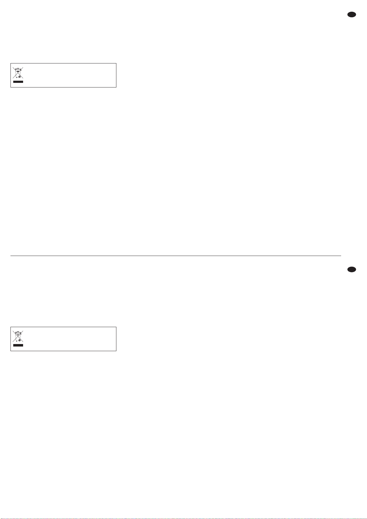
G
Utilice sólo un paño suave y seco para la limpieza,
no utilice nunca ni productos químicos ni agua.
G
No podrá reclamarse garantía o responsabilidad
alguna por cualquier daño personal o material
resultante si el aparato se utiliza para otros fines
diferentes a los originalmente concebidos, si no se
conecta correctamente, no se utiliza adecuadamente o no se repara por expertos.
3 Aplicaciones
Este amplificador para megafonía estéreo está diseñado especialmente para aplicaciones en escenario
y discoteca. El amplificador puede funcionar en
modo estéreo, en modo paralelo mono, o en modo
punteado mono. Con su circuito de salida de clase H,
funciona más eficientemente que los amplificadores
estándar con tecnología de clase AB. Debido a un
filtro conmutable, el amplificador también puede utilizarse sólo para subwoofers o sólo para frecuencias
superiores a 120 Hz. El amplificador y los altavoces
conectados están protegidos por extensos circuitos
de protección. Dos potentes ventiladores controlados por temperatura suministran la refrigeración
necesaria para el amplificador.
4 Colocación
El amplificador está previsto para un montaje en
rack (482 mm/19″), pero también puede utilizarse
como elemento de sobremesa. En todo caso, el aire
tiene que circular libremente por los huecos de ventilación para asegurar una refrigeración suficiente.
4.1 Instalación en rack
Se necesitan 2 unidades de espacio en el rack
(= 89 mm). El aire caliente expulsado por la parte
posterior del amplificador tiene que disiparse del
rack, de lo contrario la acumulación de calor no solo
puede dañar el amplificador sino también los demás
aparatos del rack. En caso de que el calor no se
disipe suficientemente, hay que insertar un ventilador en el rack.
Para prevenir el sobrepeso en la parte superior
del rack, hay que insertar el amplificador en la parte
inferior del rack. Sólo con el panel frontal no es suficiente para una fijación segura. Además, el aparato
tiene que asegurarse por la parte posterior o sostenerse mediante raíles laterales o una placa en la
parte inferior.
5 Conexión del Amplificador
Haga o cambie todas las conexiones sólo con el
aparato desconectado.
1) Conecte la salida de un preamplificador o mez-
clador a las entradas XLR INPUTS (7). Las
tomas están diseñadas para señales simétricas;
la configuración de contactos aparece en la
figura 2. Para la conexión de fuentes con señales
asimétricas, utilice un adaptador con los contac-
tos XLR 1 y 3 punteados (p. ej. el adaptador
MCA-15/2 de “img Stage Line”: jack 6,3 mm de
2 polos a toma XLR).
La señal de entrada debería tener nivel de
línea. La potencia nominal del amplificador necesita como mínimo una señal de 1 V.
Para el modo punteado o paralelo, conecte
sólo la entrada del canal izquierdo L-CH.
Mediante las salidas alimentadas (8) que se
conectan directamente a su toma de entrada respectiva (7) la señal puede alimentar, por ejemplo,
otro amplificador.
2) La potencia máxima de salida se alcanza en el
modo estéreo y en paralelo cuando se conectan
altavoces de 4 Ω (impedancia admisible mínima
con carga en potencia nominal). Sin embargo,
también pueden conectarse altavoces de 8 Ω, en
cuyo caso la potencia de salida se reduce levemente. En modo punteado, la potencia máxima
de salida se alcanza con un altavoz de 8 Ω (impedancia admisible mínima con carga en potencia
nominal con funcionamiento punteado). La
potencia necesaria (P
MIN) de los altavoces apa-
rece en la tabla de la fig. 3.
Mientras en modo paralelo o estéreo no se
exceda una potencia RMS de salida de 750 W
por canal, puede funcionar con una carga de 2 Ω.
El funcionamiento punteado con una carga de
4 Ω es posible con una potencia RMS de salida
de hasta 1500 W.
Conecte los altavoces a las tomas Speakon
®
(11, 12), ver configuración de pines en la fig. 2, o
a los terminales de tornillo (13).
Después de conectar una toma Speakon
®
a la
conexión, gírela en el sentido de las agujas del
reloj hasta que quede bien fijada. Para extraerla
más tarde, apriete hacia atrás el cierre de la toma
y gire la toma en el sentido contrario a las agujas
del reloj.
Si se utilizan los terminales de tornillo, asegúrese de que las puntas del cable no están excesivamente peladas y de que ningún hilo sobresale (peligro de contacto y de cortocircuito).
Cuando se conecten los altavoces, preste
atención a la misma polaridad de todos los altavoces.
La toma Speakon
®
de la salida L-CH (11) también está provista con las señales de la salida
derecha R-CH de modo que se pueden conectar
ambos altavoces mediante un cable de 4 polos a
esta toma.
Para el modo punteado, conecte el contacto
positivo del altavoz al terminal positivo (13) de la
salida izquierda L-CH y el contacto negativo del
altavoz al terminal positivo de la salida derecha
R-CH [ver fig. 2]. (Mediante la inversión de señal
Si va a poner el aparato fuera de servicio
definitivamente, llévelo a la planta de reciclaje más cercana para que su eliminación
no sea perjudicial para el medioambiente.
G
Do czyszczenia obudowy należy używać tylko
suchej, miękkiej ściereczki. Nie wolno używać
wody lub innych środków chemicznych.
G
Dostawca oraz producent nie ponoszą odpowiedzialności za ewentualnie wynikłe szkody materialne lub uszczerbki na zdrowiu, jeśli urządzenie
było używane niezgodnie z przeznaczeniem, zostało niepoprawnie zainstalowane lub obsługiwane
oraz było poddawane naprawom przez nieautoryzowany personel.
3 Zastosowanie
Wzmacniacz ten został specjalnie zaprojektowany
do pracy na estradzie oraz w dyskotekach. Wzmacniacz może pracować w trybie stereo, równoległym
lub w trybie mostkowym. Rozbudowane obwody
zabezpieczające chronią sam wzmacniacz oraz
dołączone zestawy głośnikowe. Dzięki układowi
końcowemu klasy H, wzmacniacz ma większą efektywność w porównaniu ze standardowymi wzmacniaczami mocy klasy AB. Dodatkowo, przełączane
filtry pozwalają na użycie tego wzmacniacza do zasilania subwoofera lub do pracy w paśmie powyżej
120 Hz. Rozbudowane obwody zabezpieczające
chronią sam wzmacniacz oraz dołączone zestawy
głośnikowe. Ponadto, urządzenie wyposażone jest
w efektywny system chłodzenia z dwoma temperaturowo sterowanymi wentylatorami.
4 Instalacja
Wzmacniacz jest przeznaczony do montażu w racku
(482 mm/19″), ale może pracować również jako
urządzenie wolnostojące. W każdym przypadku
należy zapewnić mu wystarczającą ilość miejsca
wokół otworów wentylacyjnych pozwalającą na swobodną cyrkulację powietrza.
4.1 Montaż w racku
Urządzenie ma wysokość 2 U = 89 mm. Należy zapewnić dodatkową przestrzeń nad oraz pod wzmacniaczem, w celu odpowiedniej wentylacji. W przeciwnym razie, ciepło generowane przez wzmacniacz
może spowodować uszkodzenie nie tylko wzmacniacza, ale i innych urządzeń w stojaku. W przypadku niedostatecznej wentylacji należy dodatkowo
zamontować w stojaku wentylatory.
Ze względu na wagę wzmacniacza, powinien on
być montowany na dole stojaka. Z tego samego
względu urządzeniu należy zapewnić dodatkowe
podparcie (oprócz mocowania za przedni panel).
5 Podłączanie wzmacniacza
Wszelkich połączeń należy dokonywać przy wyłączonym wzmacniaczu!
1) Połączyć wyjście przedwzmacniacza lub miksera
do gniazd wejściowych XLR INPUTS (7). Złącza
przystosowane są do sygnałów symetrycznych;
konfigurację pinów pokazano na rys. 2. Możliwe
jest również podłączanie sygnałów niesymetrycz-
nych. W tym przypadku należy wykorzystać
przejściówki XLR ze mostkowanymi pinami 1 i 3
(np. MCA-15/2 marki “img Stage Line”: 2-pin
gniazdo 6,3 mm na wtyk XLR).
Sygnał wejściowy powinien mieć poziom
liniowy. Do pełnego wysterowania wzmacniacza
potrzebne jest napięcie minimum 1 V.
Przy pracy w trybie równoległym lub mostka,
należy podłączać sygnał tylko na wejście kanału
lewego L-CH.
Poprzez przelotowe wyjścia (8), zrównoleglone z odpowiednimi gniazdami wejściowymi (7)
sygnały mogą być przesyłane dalej np. do kolejnego wzmacniacza.
2)
Maksymalną moc wyjściową w trybie stereo można
osiągnąć dla obciążenia 4 Ω (minimalna dopuszczalna impedancja obciążenia przy tej mocy).
Oczywiście możliwe jest podłączenie obciążenia
8 Ω, jednak w tym przypadku maksymalna moc
wyjściowa będzie mniejsza. Przy pracy w trybie
mostka maksymalna moc zostanie osiągnięta przy
obciążeniu 8 Ω (minimalna dopuszczalna impedancja obciążenia przy tej mocy w trybie mostka).
Wymagana minimalna moc (P
MIN
) podłączanych
głośników podana jest tabeli na rys. 3.
W trybie stereo lub równoległym, tak długo jak
moc wyjściowa RMS nie przekracza 750 W na
kanał, możliwe jest podłączenie obciążenia 2 Ω. W
trybie mostka, obciążenie 4 Ω jest dopuszczalne
przy mocy wyjściowej RMS do 1500 W.
Podłączyć głośniki do gniazd Speakon®(11,
12), konfiguracja pinów podana jest na rys. 2, lub
do terminali śrubowych (13). Przy podłączaniu
głośników należy pamiętać o konieczności jednakowej polaryzacji na wszystkich głośnikach.
Po włożeniu wtyku Speakon
®
do gniazda,
należy przekręcić go zgodnie z ruchem wskazówek zegara, aż zostanie zablokowany. Aby odłączyć wtyk, należy najpierw przekręcić go w drugą
stronę.
W przypadku wykorzystywania terminali śrubowych, upewnić się że końcówki przewodów nie
zostały odizolowane na zbyt dużej długości
(może to spowodować zwarcie na skutek zetknięcia się odizolowanych żył).
Gniazdo wyjściowe Speakon
®
dla lewego
kanału L-CH (11) jest dodatkowo rozbudowane o
styki dla kanału prawego R-CH, aby możliwe było
podłączenie głośników tylko przez to wyjście, za
pomocą kabla z 4-pinowym złączem.
W przypadku pracy mostkowej połączyć
dodatni biegun głośnika do dodatniego terminala
(13) lewego kanału L-CH, natomiast ujemny biegun głośnika do dodatniego terminala prawego
kanału R-CH [patrz rys. 2]. (Poprzez odwrócenie
sygnału w trybie mostkowym, dodatni terminal
Jeśli urządzenie nie będzie już nigdy więcej
używane, wskazane jest przekazanie go do
miejsca utylizacji odpadów, aby zostało
zniszczone bez szkody dla środowiska.
15
PL
E
Page 16
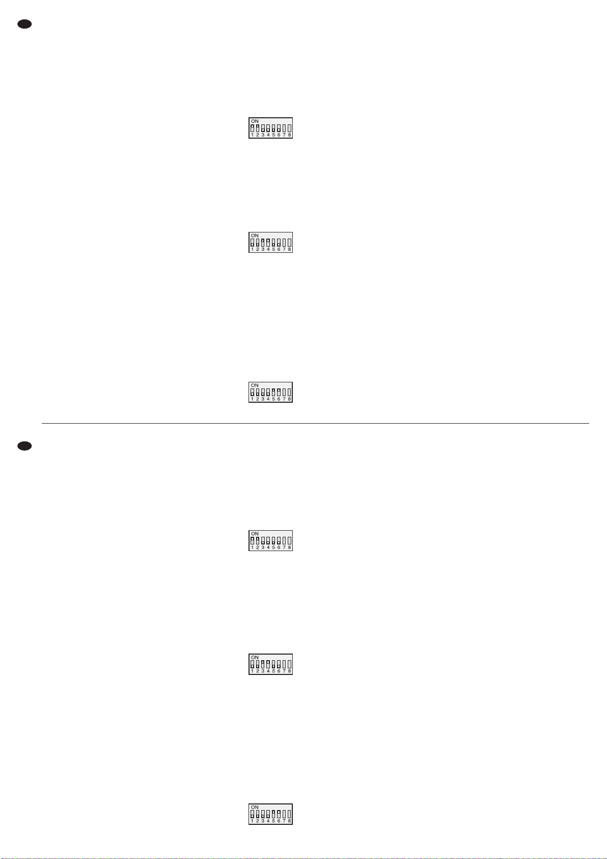
en el modo punteado, el terminal positivo de la
salida derecha se convierte en la conexión negativa del altavoz.) El altavoz puede conectarse
opcionalmente a la toma Speakon®L-CH (11).
De acuerdo con la fig. 2, conecte el terminal positivo del altavoz al contacto 1+ y el terminal negativo al contacto 2+ de la toma.
La tabla de la fig. 3 muestra las posibilidades
de conexión para varios altavoces en una
salida. En cada caso se especifica qué potencia
(P
MIN) debe tener cada altavoz como mínimo con
la impedancia correspondiente (Z). Cuando se
interconectan varios altavoces, tiene que prestarse especial atención a la correcta conexión de
los terminales positivo y negativo.
Importante: Con la potencia nominal, la impedancia total de cada salida no puede ser inferior a 4 Ω
en modo estéreo o en paralelo y no puede bajar de
8 Ω en modo punteado.
Mientras en modo paralelo o estéreo no se
exceda una potencia RMS de salida de 750 W
por canal, puede funcionar con una carga de 2 Ω.
El funcionamiento punteado con una carga de
4 Ω es posible con una potencia RMS de salida
de hasta 1500 W.
3)
El aparato se entrega sin cable de corriente. Para
la conexión, utilice un cable de corriente con toma
PowerCon®y toma de corriente con contacto protector (p. ej. AAC-115P de “img Stage Line”).
Primero conecte la toma PowerCon®a la toma
de corriente (14) y gírela en el sentido de las agujas del reloj hasta que encaje bien y luego
conecte la toma de corriente a un enchufe
(230 V~/ 50 Hz). Para separarla de la corriente,
primero desconecte la toma de corriente y luego,
para quitar la toma PowerCon®, tire hacia atrás
del cierre y gírela en el sentido contrario a las
agujas del reloj.
Asegúrese de que el circuito de corriente al
cual está conectado el aparato está provisto con
un fusible de valor elevado (16 A).
6 Funcionamiento
6.1 Selección del modo de funcionamiento
Seleccione el modo de funcionamiento mediante los
interruptores DIP MODE 1 a 6 (9):
Modo estéreo – “
MODE STEREO”
En modo estéreo, ambos canales funcionan independientemente.
Configuración de interruptore
STEREO
Modo paralelo – “
MODE PARALLEL”
El modo paralelo se recomienda para ofrecer aplicaciones para megafonía p. ej. en dos salas con la
misma señal mono y la capacidad de ajustar el volumen individualmente.
La señal de entrada se conmuta internamente
desde el canal izquierdo además al canal derecho.
La señal del canal derecho se ignora. El volumen se
ajusta por separado en ambas salidas.
Configuración de interruptores
PARALLEL
Modo punteado – “
MODE BRIDGE”
El modo punteado (BRIDGE) sirve para obtener una
potencia mayor en un altavoz.
Para ello, los dos canales del amplificador se
combinan para crear un amplificador mono: Además, la señal de entrada del canal izquierdo pasa al
canal derecho de modo invertido. De este modo, el
voltaje en la salida se duplica si el altavoz está
conectado en modo punteado, como se describe en
el apartado 5. La señal del canal derecho se ignora.
El volumen se ajusta con el control izquierdo (1)
para ambas salidas.
Configuración de interruptores
BRIDGE
6.2 Filtro
El filtro integrado puede utilizarse como crossover
para recintos de 2 vías (subwoofer/satélite). Seleccione la función correspondiente del altavoz conectado con el interruptor FILTER (10).
Posición SUBWOOFER:
Filtro pasa bajo con
-
6 dB a 120 Hz
para altavoces de graves
Posición SATELLITE:
Filtro pasa alto con
-
6 dB a 120 Hz
para altavoces de medios-agudos
Posición FULLRANGE:
Sin filtro para altavoces Full Range
6.3 Conexión/Desconexión
Para prevenir un ruido fuerte de conexión, conecte
siempre el amplificador en un sistema amplificado
después de que todos los demás aparatos estén
conectados y desconéctelo siempre en primer lugar
después de utilizarlo. Antes de la primera conexión,
coloque los controles (1 y 5) en el tope izquierdo a
“-80 dB”.
Conecte el amplificador con el interruptor
POWER (6). Los LEDs ACTIVE (2, 4) sirven como
indicadores de potencia y el visualizador (3) muestra el modo de funcionamiento seleccionado. Después de la conexión, los LEDs rojos PROTECT
(2, 4) se iluminan durante un breve periodo de
tiempo. Durante este tiempo, se activa el retraso de
conexión para proteger los altavoces.
6.4 Ajuste de nivel
Ajuste la salida del mezclador o del preamplificador
a su nivel medio (0 dB) o a la señal de salida máxima
sin distorsión. Gire los controles (1 y 5) hasta que se
alcance el volumen máximo deseado. Los LEDs
“-25 dB”, “-20 dB”, y “-15 dB” (2, 4) muestran el
nivel de entrada ajustado. Si se iluminan los LEDs
rojos LIMITER, se activa el circuito limitador y pre-
prawego kanału staje się ujemnym złączem).
Głośnik można również podłączyć do gniazda
Speakon®L-CH (11). Zgodnie z rys. 2 połączyć
dodatni biegun głośnika do styku 1+, a ujemny
biegun do styku 2+ we wtyku.
Tabela na rys. 3 pokazuje także sposoby
podłączania kilku głośników do jednego wyjścia. W każdym przypadku należy przestrzegać
minimalnej mocy głośników (P
MIN) oraz minimal-
nej dopuszczalnej impedancji podłączanego
układu głośników (Z). Przy podłączaniu kilku
głośników należy zwrócić szczególną uwagę na
ich polaryzację.
Uwaga: Przy mocy znamionowej, wypadkowa
impedancja obciążenia na każdym wyjściu nie
może spaść poniżej 4 Ω w trybie stereo i równoległym, oraz 8 Ω w trybie mostka!
W trybie stereo lub równoległym, tak długo jak
moc wyjściowa RMS nie przekracza 750 W na
kanał, możliwe jest podłączenie obciążenia 2 Ω. W
trybie mostka, obciążenie 4 Ω jest dopuszczalne
przy mocy wyjściowej RMS do 1500 W.
3) Wzmacniacz dostarczany jest bez kabla zasilającego. Do podłączania zasilania należy wykorzystać kabel z wtykiem PowerCon®oraz uziemioną
wtyczką sieciową (np. AAC-115P marki “img
Stage Line”).
W pierwszej kolejności podłączyć kabel zasi-
lający do gniazda PowerCon
®
(14) i zablokować
go przekręcając zgodnie z ruchem wskazówek
zegara, a następnie do gniazdka sieciowego
(230 V~/ 50 Hz). Odłączając urządzenie od
gniazdka sieciowego, należy najpierw odłączyć
kabel od gniazdka sieciowego, a dopiero potem
od gniazda PowerCon®na urządzeniu.
Upewnić się, że istniejąca instalacja zasilająca, jest zabezpieczona bezpiecznikiem o
wystarczającej wartości (16 A).
6 Obsługa
6.1 Wybór trybu pracy
Do wyboru trybu pracy służą przełączniki DIP MODE
nr 1 do 6 (9):
Tryb Stereo – “
MODE STEREO”
W trybie STEREO, oba kanały działają niezależnie.
ustawienie przełączników
STEREO
Tryb równoległy – “MODE PARALLEL”
Tryb równoległy zalecany jest w przypadku wykorzystywania wzmacniacza do równoczesnego
nagłośnienia dwóch pomieszczeń tym samym sygnałem mono i z niezależną regulacją głośności.
Sygnał z wejścia jest wewnętrznie przełączany z
lewego kanału dodatkowo na kanał prawy. Sygnał z
wejścia prawego kanału jest ignorowany. Możliwa
jest niezależna regulacja głośności dla obu kanałów.
ustawienie przełączników
PARALLEL
Tryb mostkowy – “
MODE BRIDGE”
Tryb mostkowy BRIDGE służy do wykorzystywania
całej mocy wzmacniacza do zasilenia jednego głośnika.
W tym przypadku oba kanały wzmacniacza są
łączone w jeden kanał mono: sygnał wejściowy z
lewego kanału jest dodatkowo, po odwróceniu,
podawany na prawy kanał. W związku z tym, w trybie mostkowym napięcie na wyjściu ma podwójną
wartość, patrz rozdz. 5. Sygnał z wejścia prawego
kanału jest ignorowany. Regulacja głośności dla obu
wyjść odbywa się za pomocą pokrętła (1) dla kanału
lewego.
ustawienie przełączników
BRIDGE
6.2 Filtr
Wbudowany filtr może być używany jako zwrotnica,
dla 2-drożnych systemów głośnikowych (subwoofer/satelity). Wybrać odpowiednie ustawienie przełącznika FILTER (10), w zależności od żądanej funkcji.
Pozycja SUBWOOFER:
Filtr dolnoprzepustowy
-
6 dB przy 120 Hz
dla głośników basowych
Pozycja SATELLITE:
Filtr górnoprzepustowy
-
6 dB przy 120 Hz
dla głośników średnio-wysokotonowych
Pozycja FULLRANGE:
bez filtru, dla głośników pełnopasmowych
6.3 Włączanie/wyłączanie wzmacniacza
Aby uniknąć trzasku w głośnikach, należy włączać
wzmacniacz na końcu, po wszystkich źródłach sygnału, natomiast wyłączać jako pierwszy. Przed
pierwszym włączeniem wzmacniacza, ustawić regulatory (1 i 5) maksymalnie w lewo, na “
-
80 dB”. Włączyć urządzenie włącznikiem POWER (6). Po włączeniu wzmacniacza zapalą się diody ACTIVE
(2, 4), a na wyświetlaczu (3) pojawi się ustawiony
tryb pracy. Zapalą się również, na krótko diody PROTECT (2, 4). W tym czasie aktywny jest obwód opóźnionego złączania głośników.
6.4 Ustawienie poziomu głośności
Ustawić poziom sygnału wyjściowego miksera lub
przedwzmacniacza na nominalny poziom (0dB) lub
na maksymalny dający niezniekształcony sygnał.
Ustawić za pomocą regulatorów (1 i 5) maksymalną
żądaną głośność. Wskaźniki diodowe “
-
25 dB”,
“
-
20 dB” oraz “-15 dB” (2, 4) wskazują bieżący
poziom sygnału wejściowego. Zapalenie się czerwonych diod LIMITER oznacza przesterowanie sygnału, należy odpowiednio skręcić regulatory.
16
E
PL
Page 17
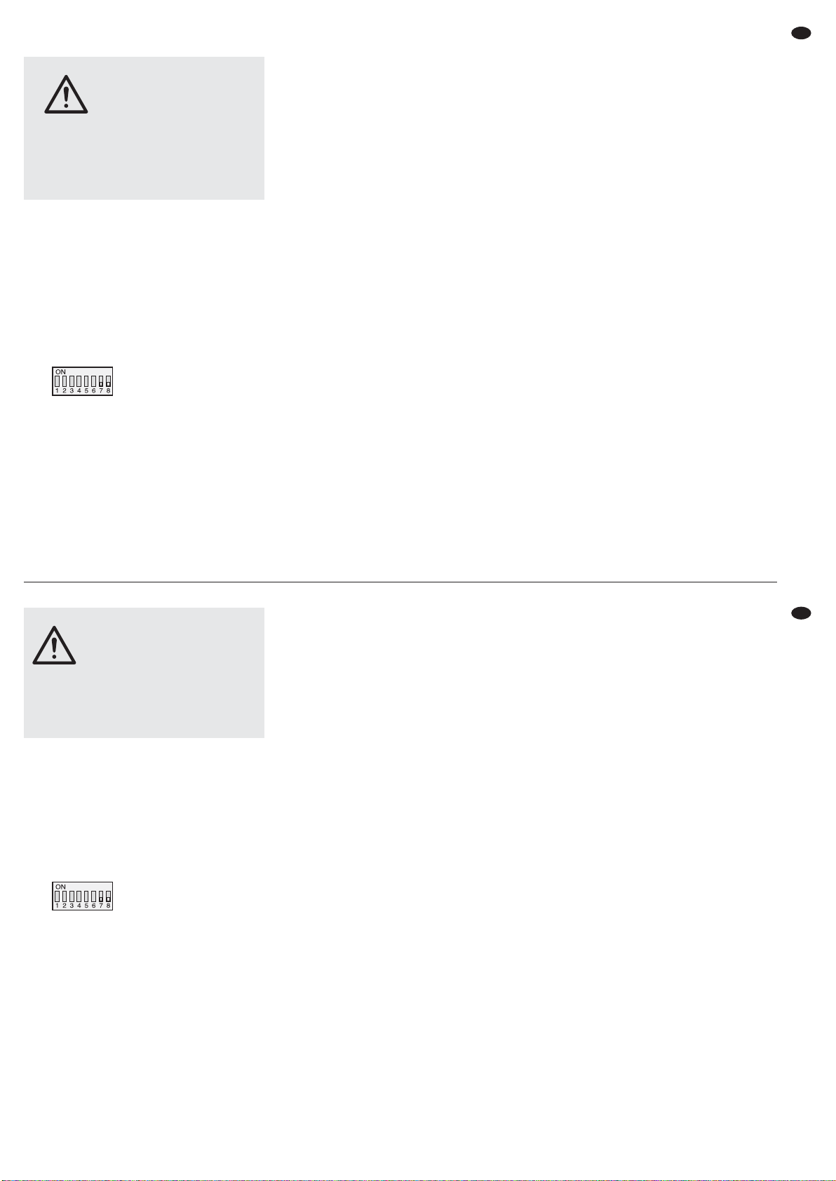
viene la sobrecarga del amplificador. En este caso
baje levemente los controles.
6.5 Interruptor Groundlift
Si se escucha un zumbido de interferencia sin señal
de música, puede que la razón sea un bucle de
masa. Los bucles de masa pueden aparecer si dos
aparatos tienen contacto mediante la masa de la
señal y el conductor protector de la alimentación o
una conexión conductiva de las carcasas en el rack.
Para separar el bucle que se ha creado, cambie los
interruptores DIP 7 y 8 (9) de la posición superior a
la inferior.
Configuración de interruptores
Groundlift
7 Circuitos de Protección
Los circuitos de protección están previstos para prevenir daños en los altavoces y en el amplificador. El
limitador de nivel integrado reduce la señal de
entrada cuando se alcanza el nivel del límite en la
salida. De este modo, en caso de sobrecarga del
amplificador, pueden prevenirse las distorsiones
que pueden dañar los altavoces. Si el limitador está
activo, el LED LIMITER (2, 4) del canal correspondiente se ilumina.
Debido a un circuito de protección adicional, los
altavoces están separados desde la salida del canal
que le concierne. Si está activo, el LED rojo PROTECT (2, 4) del canal correspondiente se ilumina:
1. Durante unos instantes después de la conexión
(retraso de conexión)
2. En caso de sobrecarga/sobrecalentamiento (p.ej.
por un cortocircuito en la salida o cuando se
excede la potencia de salida admisible en funcio-
namiento estéreo/paralelo a 2 Ω o funciona-
miento punteado a 4 Ω)
3. Si hay voltaje CC en la salida
Durante el funcionamiento normal, la temperatura
en los transistores se muestra en el visualizador (3)
separadamente para ambos canales. Con temperaturas más elevadas, el control del ventilador asegura que el ventilador del canal afectado funciona a
una velocidad más grande.
En caso de error, p. ej. por un cortocircuito en una
salida, el visualizador cambia a “
SHORT CIR.PROT,
OVERLOAD&FAULT
” (además, el LED PROTECT del
canal afectado se ilumina).
En este caso, o si el LED PROTECT no se apaga
después de la conexión, o si el interruptor de protección (15) se ha liberado, el amplificador tiene que
desconectarse y eliminar la causa del error. Si es
necesario, recoloque el interruptor de protección
pulsándolo.
ADVERTENCIA No ajuste nunca el altavoz en un
volumen muy elevado. Los volúmenes permanentes muy elevados pueden dañar su oído. El
oído humano se acostumbra a
los volúmenes altos que no lo
parecen tanto después de un
rato. Por lo tanto, no aumente un
volumen alto que ya se había
ajustado antes de acostumbrarse a él.
6.5 Przełącznik Groundlift
W przypadku wystąpienia charakterystycznego
przydźwięku lub buczenia w głośnikach, słyszanego
w przerwach między muzyką, spowodowanego
wystąpieniem pętli masy (jeżeli zarówno wzmacniacz jak i źródła sygnału podłączone są do zasilania uziemionymi kablami), należy włączyć separację
masy, ustawiając przełączniki DIP nr 7 i 8 (9) w
dolną pozycję.
ustawienie przełącznika
Groundlift
7 Obwody zabezpieczające
Obwody zabezpieczające służą do ochrony wzmacniacza oraz głośników przed uszkodzeniem, natomiast wbudowany limiter ogranicza poziom sygnału
wejściowego w przypadku przekroczenia dopuszczalnego poziomu sygnału na wyjściu. Dzięki temu,
zarówno w przypadku przeciążenia jak i wystąpienia
zakłóceń, podłączone głośniki są chronione przed
uszkodzeniem. Jeżeli limiter jest aktywny, zapalają
się diody LIMITER (2, 4) na odpowiednich kanałach.
Dzięki dodatkowym obwodom zabezpieczającym
następuje odseparowanie głośników, sygnalizowane zapaleniem się diod PROTECT (2, 4):
1. na krótki czas po włączeniu (opóźnione załącza-
nie)
2. w przypadku przeciążenia/przegrzania (np. także
w przypadku zwarcia na wyjściu – gdy impedan-
cja obciążenia spadnie poniżej dopuszczalnej
wartości lub gdy przekroczona zostanie dopusz-
czalna moc wyjściowa przy 2 Ω w trybie ste-
reo/równoległym lub 4 Ω w trybie mostka)
3. w przypadku pojawienia się napięcia stałego DC
na wyjściu
Podczas normalnej pracy na wyświetlaczu (3) poka-
zywana jest bieżąca temperatura na tranzystorach
mocy obu kanałów. W przypadku przekroczenia
dopuszczalnej wartości, następuje automatyczne
ustawienie odpowiedniej prędkości wentylatorów
chłodzących.
W przypadku wystąpienia błędu np. zwarcia na
wyjściu, na wyświetlaczu (3) pojawia się “SHORT
CIR.PROT, OVERLOAD&FAULT
” oraz zapala się
dioda PROTECT.
W sytuacji kiedy dioda PROTECT nie zgasła po
włączeniu, lub zadziałał przełącznik zabezpieczający (15), należy wyłączyć wzmacniacz i usunąć
przyczynę usterki. Jeżeli zajdzie potrzeba należy
wciśnąć przycisk bezpiecznika.
UWAGA Nigdy nie ustawiać bardzo dużej głoś-
ności wzmacniacza! Stały, bardzo
wysoki poziom dźwięku może uszkodzić narząd słuchu. Ucho ludzkie
adaptuje się do wysokiego poziomu
dźwięku, który po pewnym czasie nie
jest już percepowany jako wysoki.
Dlatego nie wolno przekraczać raz
już ustawionego maksymalnego
poziomu głośności.
17
PL
E
Page 18
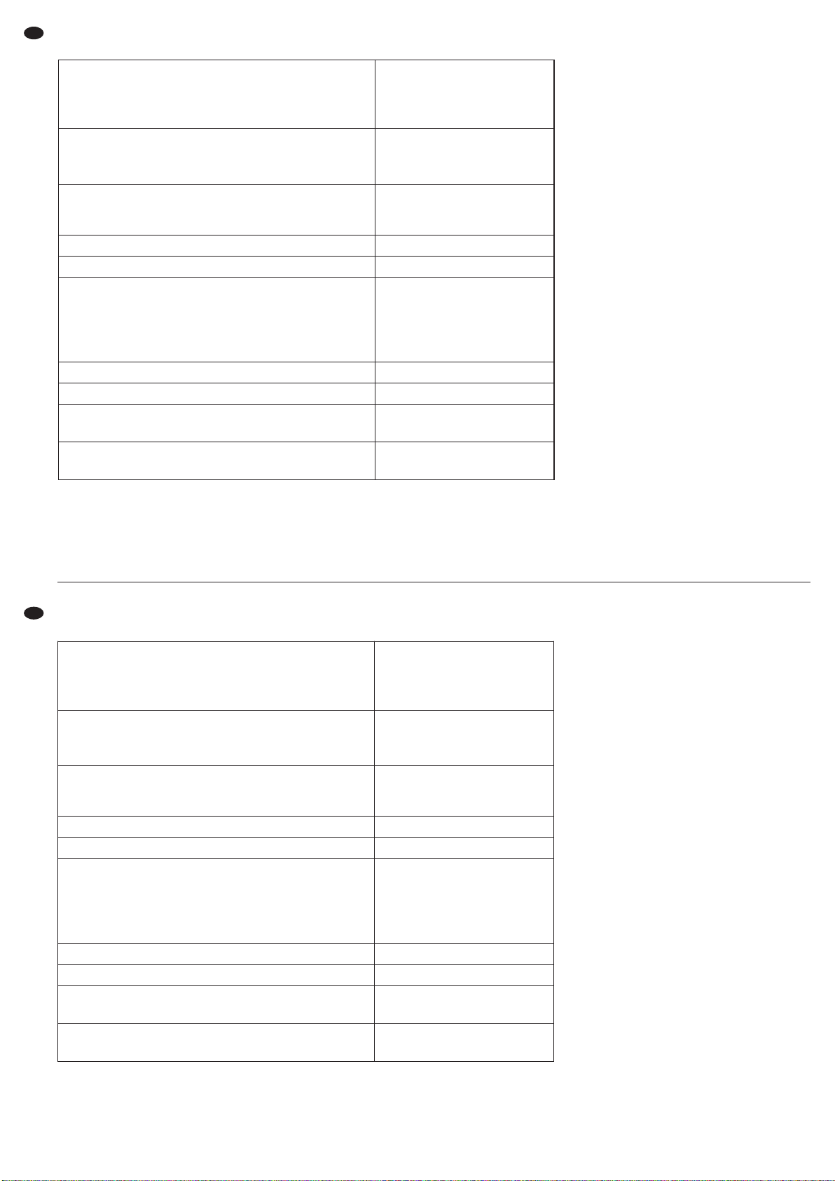
8 Especificaciones
Sujeto a modificaciones técnicas.
8 Specyfikacja
Z zastrzeżeniem możliwości zmian.
18
E
PL
Manual de instrucciones protegido por el copyright de MONACOR®INTERNATIONAL GmbH & Co. KG.
Toda reproducción mismo parcial para fines comerciales está prohibida.
Potencia RMS de salida (potencia nominal)
(1 kHz, 0,1 % THD+N)
Estéreo, paralelo a 4 Ω
Estéreo, paralelo a 8 Ω
Modo punteado a 8 Ω
2 × 1100 W
2 × 700 W
2000 W
Máxima potencia RMS de salida admisible
a impedancia más baja con carga
Estéreo, paralelo a 2 Ω
Modo punteado a 4 Ω
2 × 750 W
1500 W
Sensibilidad de entrada
para nivel a 8 Ω
Impedancia de entrada sim./asim.
1V
20 kΩ/10 kΩ
Rango de frecuencias con 1 W a 8 Ω 20 – 20 000 Hz (±0,3 dB)
Filtro pasa alto/filtro pasa bajo 120 Hz (-6 dB), 24 dB/ octava
Factor de atenuación a 8 Ω
THD*
Separación de canal*
Relación ruido/sonido con potencia a 8 Ω
*20 Hz – 20 kHz con potencia a 8Ω
> 300
< 0,1 %
> 60 dB
> 100 dB
Circuito de salida Clase H
Temperatura ambiente 0 – 40 °C
Alimentación
Consumo máximo
230 V~ / 50 Hz
3600 VA
Dimensiones (B × H × P)
Peso
482 × 88 × 479 mm, 2 U
23 kg
Moc wyjściowa RMS (moc znamionowa)
(1 kHz, 0,1 % THD+N)
Stereo, równoległa przy 4 Ω
Stereo, równoległa przy 8 Ω
W mostku przy 8 Ω
2 × 1100 W
2 × 700 W
2000 W
Maksymalna dopuszczalna moc RMS
przy niższym obciążeniu
Stereo, równoległa przy 2 Ω
W mostku przy 4 Ω
2 × 750 W
1500 W
Czułość wejścia dla
mocy znamionowej przy 8 Ω
Impedancja wejściowa sym./niesym.
1V
20 kΩ/10 kΩ
Pasmo przenoszenia dla 1 W przy 8 W 20 – 20 000 Hz (±0,3 dB)
Filtr górnoprzepustowy/dolnoprzepustowy 120 Hz (-6 dB), 24 dB/ oktawę
Współczynnik tłumienia przy 8 Ω
THD*
Separacja kanałów*
Stosunek S/N dla mocy znamionowej przy 8 Ω
*20 Hz – 20 kHz dla mocy znamionowej przy 8Ω
> 300
< 0,1 %
> 60 dB
> 100 dB
Układ końcowy klasa H
Zakres temperatur 0 – 40 °C
Zasilanie
Max pobór mocy
230 V~ / 50 Hz
3600 VA
Wymiary (S × W × G)
Waga
482 × 88 × 479 mm, 2 U
23 kg
Instrukcje obsługi są chronione prawem copyright for MONACOR®INTERNATIONAL GmbH & Co. KG.
Przetwarzanie całości lub części instrukcji dla osobistych korzyści finansowych jest zabronione.
Page 19

19
Page 20
20
Lees aandachtig de onderstaande veiligheidsvoorschriften, alvorens het toestel in gebruik te ne men.
Mocht u bijkomende informatie over de bediening
van het toestel nodig hebben, lees dan de En gelse
tekst van deze hand lei ding.
Veiligheidsvoorschriften
Dit apparaat is in overeenstemming met alle vereiste
EU-Richtlijnen en is daarom gekenmerkt met .
Let eveneens op het volgende:
G
Het toestel is enkel geschikt voor gebruik binnenshuis. Vermijd druip- en spatwater, uitzonderlijk warme plaatsen en plaatsen met een hoge
vochtigheid (toegestaan omgevingstemperatuurbereik: 0 – 40 °C).
G
Plaats geen bekers met vloeistof zoals drinkglazen etc. op het toestel.
G
De warmte die in het toestel ontstaat, moet door
ventilatie afgevoerd worden. Zorg er daarom voor,
dat de ventilatieopeningen van de kast door geen
enkel voorwerp afgedekt worden.
G
Schakel het toestel niet in resp. trek onmiddellijk
de stekker uit het stopcontact:
1. wanneer het toestel of het netsnoer zichtbaar
beschadigd is,
2. wanneer er een defect zou kunnen optreden
nadat het toestel bijvoorbeeld gevallen is,
3. wanneer het toestel slecht functioneert.
Het toestel moet in elk geval hersteld worden door
een gekwalificeerd vakman.
G
Trek de stekker nooit met het snoer uit het stopcontact, maar met de stekker zelf.
G
Gebruik voor de reiniging uitsluitend een droge,
zachte doek. Gebruik in geen geval chemicaliën of
water.
G
In geval van ongeoorloofd of verkeerd gebruik,
verkeerde aansluiting, foutieve bediening of van
herstelling door een niet-gekwalificeerd persoon
vervalt de garantie en de verantwoordelijkheid
voor hieruit resulterende materiële of lichamelijke
schade.
WAARSCHUWING De netspanning (230 V~) van
het apparaat is levensgevaarlijk. Open het apparaat
niet, en zorg dat u niets in de
ventilatieopeningen steekt! U
loopt het risico van een elek-
trische schok.
Tijdens het gebruik staan de luid sprekeraansluitingen onder een levensgevaarlijke spanning. De inen uitgangen mo gen enkel aangesloten en ge wijzigd
worden, wanneer het apparaat uitgeschakeld is.
Wanneer het toestel definitief uit bedrijf
genomen wordt, bezorg het dan voor
milieuvriendelijke verwerking aan een
plaatselijk recyclagebedrijf.
Læs nedenstående sikkerhedsoplys ninger opmærk somt igennem før ibrugtagning af enheden. Bortset
fra sikkerhedsoplys nin gerne henvises til den engelske tekst.
Vigtige sikkerhedsoplysninger
Denne enhed overholder alle de påkrævede EU
direktiver, og er derfor mærket med .
Vær altid opmærksom på følgende:
G
Enheden er kun beregnet til indendørs brug. Be skyt den mod vanddråber og -stænk, høj luft fugtig hed og varme (tilladt om givelses tem pera tur
0 – 40 °C).
G
Undgå at placere væskefyldte genstande, som
f. eks. glas, ovenpå enheden.
G
Varmen, der udvikles i enheden, skal kunne slippe
ud ved hjælp af luftcirkulation. Ventilationshullerne
i kabinettet må derfor ikke tildækkes.
G
Tag ikke enheden i brug og tag straks stikket ud af
stikkontakten i følgende tilfælde:
1. hvis der er synlig skade på enheden eller netkablet,
2. hvis der kan være opstået skade, efter at enheden er tabt eller lignende,
3. hvis der forekommer fejlfunktion.
Enheden skal altid repareres af autoriseret per sonel.
G
Tag aldrig netstikket ud af stikkontakten ved at
træk ke i kablet, tag fat i selve stikket.
G
Til rengøring må kun benyttes en tør, blød klud;
der må under ingen omstændigheder benyttes
kemikalier eller vand.
G
Hvis enheden benyttes til andre formål, end den
oprindeligt er beregnet til, hvis den ikke er tilsluttet
korrekt, hvis den betjenes forkert, eller hvis den
ikke repareres af autoriseret personel, omfattes
eventuelle skader ik ke af ga rantien.
ADVARSEL Dette produkt benytter 230 V~. Udfør
aldrig nogen form for modifikationer
på produktet og indfør aldrig genstande i ventilationshullerne, da du
dermed risikere at få elektrisk stød.
Der er farlig spænding til stede på højttalertilslutningerne under drift. Alle tilslutninger må kun udføres resp. ændres, mens enheden er slukket.
Hvis enheden skal tages ud af drift for
bestandigt, skal den bringes til en lokal
genbrugsstation for bortskaffelse.
Innan enheten tas i bruk, läs först igenom säkerhets föreskrifterna. Om ytterligare information önskas, läs
igenom den engelska texten som medföljer.
Säkerhetsföreskrifter
Enheten uppfyller samtliga EG-direktiv och har därför märkts med symbolen .
Ge ovillkorligen även akt på följande:
G
Enheten är endast avsedda för in om hus bruk. Skyd da enheten mot vätskor, hög luftfuktighet och hög
värme (tillåten omgivnings temperatur 0 – 40°C).
G
Placera inte föremål innehållande vätskor, t. ex.
drick sglas, på enheten.
G
Värmen som alstras vid användning leds bort
genom självcirkulering, täck därför aldrig över kylhålen så att cirkulationen försämras.
G
Använd inte enheten och ta omedelbart kontakten
ur eluttaget om något av följande fel uppstår:
1. Enheten eller elsladden har synliga skador.
2. Enheten är skadad av fall e. d.
3. Enheten har andra felfunktioner.
Enheten skall alltid lagas på verkstad av ut bildad
personal.
G
Drag aldrig ut kontakten genom att dra i el sladden
utan ta tag i kontaktkroppen.
G
Rengör endast med en mjuk och torr trasa, an vänd aldrig kemikalier eller vatten vid ren göring.
G
Om enheten används för andra ändamål än av sett, om den kopplas in felaktigt, om den an vänds
på fel sätt eller inte repareras av auktoriserad per-
sonal upphör alla garantier att gälla och inget
ansvar tas heller för uppkommen skada på person
eller materiel.
Om enheten skall kasseras bör de lämnas
in till återvinning.
VARNING Enheten använder hög spänning in -
ternt (230 V~). Gör inga modifieringar
i enheten eller stoppa föremål i ventilhålen. Risk för elskador föreligger.
Högtalaranslutningarna bär hög spän ning vid användning, undvik därför att
röra dessa då förstärkaren är i drift.
Alla in resp. urkopplingar skall göras
endast då förstärkaren är avstängd.
NL
B
DK
S
Page 21
21
Ole hyvä ja huomioi aina seuraavat turvallisuutta
kos kevat ohjeet ennen laitteen käyttöönottoa. Katso
käyttöön liittyviä ohjeita Englanninkielisistä ohjeista,
jos tarvitset lisää tietoa laitteen käytöstä.
Turvallisuudesta
Tämä laite täyttää kaikki siihen kohdistuvat EUdirektiivit ja sille on myönnetty hyväksyntä.
Huomioi seuraavat seikat:
G
Tämä laite soveltuu vain sisätilakäyttöön. Suojele
lai tetta kosteudelta, vedeltä ja kuumuudelta (sallittu ympä röivä lämpötila 0 –40 °C).
G
Älä sijoita laitteen päälle mitään nestettä sisältävää, kuten vesilasia tms.
G
Laitteessa syntyvä lämpö johdetaan laiteesta il mankierron avulla. Sen vuoksi kotelon ilma-aukkoja ei saa peittää.
G
Irrota virtajohto pistorasiasta, äläkä käynnistä laitetta jos:
1. virtajohdossa on havaittava vaurio
2. putoaminen tai muu vastaava vahinko on saattanut aiheuttaa vaurion
3. laitteessa esiintyy toimintahäiriöitä
Kaikissa näissä tapauksissa laite tulee toimittaa
valtuutettuun huoltoliikkeeseen.
G
Älä koskaan irrota virtajohtoa pistorasiasta johdosta vetämällä.
G
Käytä puhdistamiseen pelkästään kuivaa, pehmeää kangasta. Älä käytä kemikaaleja tai vettä.
G
Laitteen takuu raukeaa, eikä valmistaja, maahantuoja tai myyjä ota vastuuta mahdollisista välittö -
mis tä tai välillisistä vahingoista, jos laitetta on
käytetty muuhun kuin alkuperäiseen käyttötarkoitukseen, laitet ta on taitamattomasti käytetty tai
kytketty tai jos laitetta on huollettu muussa kuin
valtuutetussa huollossa.
VAROITUS Tämä laite toimii vaarallisella 230 V~
jännitteellä. Älä koskaan tee mitään
muutoksia laitteeseen taikka asenna
mitään ilmanvaihto aukkoihin, koska
siitä saattaa seurata sähköisku.
Kaiutinliittimistä on mahdollista saada sähköisku.
Käytön aikana liittimissäon vaarallisen korkea jännite. Kaikki kytkennät tulee suorittaa laitteen
ollessa sammutettuna.
Kun laite poistetaan lopullisesti käytösta,
vie se paikalliseen kierrätyskeskukseen
jälkikäsittelyä varten.
FIN
Page 22

®
MONACOR INTERNATIONAL GmbH & Co. KG •Zum Falsch 36 •28307 Bremen •Germany
Copyright
©
by MONACOR INTERNATIONAL. All rights reserved. A-0936.99.02.11.2012
 Loading...