

Monacor STA-1504, STA-1508, STA-1506 Instruction Manual
ELECTRONICS FOR SPECIALISTS ELECTRONICS FOR SPECIALISTS ELECTRONICS FOR SPECIALISTS ELECTRONICS FOR SPECIALISTS
BEDIENUNGSANLEITUNG
INSTRUCTION MANUAL
MODE D’EMPLOI
ISTRUZIONI PER L’USO
GEBRUIKSAANWIJZING
MANUAL DE INSTRUCCIONES
INSTRUKCJA OBSŁUGI
SIKKERHEDSOPLYSNINGER
SÄKERHETSFÖRESKRIFTER
TURVALLISUUDESTA
Mehrkanal-PA-Verstärker
Multichannel PA Amplifier
STA-1504
Bestell-Nr. • Order No. 24.4280
STA-1506 Bestell-Nr. • Order No. 24.4290
STA-1508 Bestell-Nr. • Order No. 24.4300

2
Deutsch ...........Seite 4
English ............Page 6
Français ...........Page 8
Italiano............Pagina 10
Nederlands ........Pagina 12
Español ...........Página 14
Polski .............Strona 16
Dansk .............Sida 18
Svenska ...........Sidan 18
Suomi.............Sivulta 19
ELECTRONICS FOR SPECIALISTS ELECTRONICS FOR SPECIALISTS ELECTRONICS FOR SPECIALISTS ELECTRONICS FOR SPECIALISTS
3
CLIP
+3
0dB
–5
–10
–15
–25
CLIP
+3
0dB
–5
–10
–15
–25
BRIDGE BRIDGE
CH-5 CH-6 CH-7 CH-8
CLIP
+3
0dB
–5
–10
–15
–25
BRIDGE
CLIP
+3
0dB
–5
–10
–15
–25
BRIDGE
CH-1 CH-2 CH-3 CH-4
STA-1508
POWER
231
+
–
+
–
+
–
+
–
+
–
+
–
+
–
231 231 231 231 231 231 231
2 1
3
2 1
3
2 1
3
2 1
3
2 1
3
2 1
3
2 1
3
2 1
3
GROUND LIFT
GND
LIFT
CH 7
NORMAL
BRIDGE
BRIDGED MODE
CH 5
BRIDGED MODE
CH 4 CH 3 CH 2 CH1CH 8
GND
SIG
INPUT
INPUT
ALT.
GND
SIGNAL
SIGNAL
LEVEL
HI-PASS
LO-PASS
BYPASS
FILTER
OUTPUT
230V~/ 50Hz
FUSE
CH 6
NORMAL
BRIDGE
NORMAL
BRIDGE
BRIDGED MODE
NORMAL
BRIDGE
BRIDGED MODE
NORMAL
BRIDGE
MAINS
GND
SIG
INPUT
INPUT
ALT.
GND
SIGNAL
SIGNAL
LEVEL
HI-PASS
LO-PASS
BYPASS
FILTER
OUTPUT
GND
SIG
INPUT
INPUT
ALT.
GND
SIGNAL
SIGNAL
LEVEL
HI-PASS
LO-PASS
BYPASS
FILTER
OUTPUT
GND
SIG
INPUT
INPUT
ALT.
GND
SIGNAL
SIGNAL
LEVEL
HI-PASS
LO-PASS
BYPASS
FILTER
OUTPUT
GND
SIG
INPUT
INPUT
ALT.
GND
SIGNAL
SIGNAL
LEVEL
HI-PASS
LO-PASS
BYPASS
FILTER
OUTPUT
GND
SIG
INPUT
INPUT
ALT.
GND
SIGNAL
SIGNAL
LEVEL
HI-PASS
LO-PASS
BYPASS
FILTER
OUTPUT
GND
SIG
INPUT
INPUT
ALT.
GND
SIGNAL
SIGNAL
LEVEL
HI-PASS
LO-PASS
BYPASS
FILTER
OUTPUT
GND
SIG
INPUT
INPUT
ALT.
GND
SIGNAL
SIGNAL
LEVEL
HI-PASS
LO-PASS
BYPASS
FILTER
OUTPUT
1
2 4
5
3
6
7
8
9
10
11
12
14
13
➀
➁
➂
➃
➄
➅ ➆
➇
➈
➉
Anschlussmöglichkeit
je Ausgang
Connecting possibility
peroutput
Betriebsart
Mode
Z je Lautsprecher
Z per speaker
P
min
je Lautsprecher
Z
min
per speaker
+
-
NORMAL 4 Ω 160 W
NORMAL
8 Ω 100 W
BRIDGE
8 Ω 320 W
+
-
+
-
NORMAL 8 Ω 80 W
NORMAL
16 Ω 50 W
BRIDGE
16 Ω 160 W
+
-
+
-
NORMAL 4 Ω 50 W
BRIDGE
4 Ω 160 W
BRIDGE
8 Ω 100 W
+
-
+
-
+
-
+
-
NORMAL 4 Ω 40 W
NORMAL
8 Ω 25 W
BRIDGE
8 Ω 80 W
2 1
3
2
1
3
=
=
=
GND
SIGNAL
+
–
SIGNAL
INPUT
AL T.
OUTPUT
1
2
3
4
5
+
-
BYPASS
INPUT OUTPUT
LEVEL
+
-
BYPASSLEVEL
+
-
BYPASSLEVEL
+
-
BYPASSLEVEL
~A
~A
~B
~
B
~C
~
C
~D
~
D
NORMAL
NORMAL
CH1
CH2
CH3
CH4
+
-
BYPASS
INPUT OUTPUT
LEVEL
+
-
BYPASSLEVEL
+
-
BYPASSLEVEL
+
-
BYPASSLEVEL
NORMAL
NORMAL
~A
~A
~A
~A
~A
CH1
CH2
CH3
CH4
INPUT OUTPUT
BYPASSLEVEL
BYPASSLEVEL
BRIDGE
+
-
+
-
~A
~B
~A
~B
BRIDGE
CH1
CH2
CH3
CH4
–
+
–
+
+
-
FILTER
INPUT OUTPUT
LEVEL
+
-
HI-PASS
FILTERLEVEL
LO-PASS
FILTERLEVEL
HI-PASS
FILTERLEVEL
LO-PASS
+
-
+
-
~A HIGH
~A LOW
~
B HIGH
~A
~B
~B LOW
NORMAL
NORMAL
CH1
CH2
CH3
CH4
BYPASS
INPUT OUTPUT
LEVEL
HI-PASS
FILTERLEVEL
BRIDGE
FILTERLEVEL
LO-PASS
+
-
~
B HIGH
~B
~B LOW
+
-
~A~A
NORMAL
CH1
CH2
CH3
CH4
–
+
+
-
4
Deutsch
Mehrkanal-PA-Verstärker
Diese Anleitung richtet sich an Fachleute mit
Kenntnissen in der Beschallungstechnik. Bitte
lesen Sie die Anleitung vor dem Betrieb gründlich durch und heben Sie sie für ein späteres
Nachlesen auf. Auf der ausklappbaren Seite 3
finden Sie alle beschriebenen Bedienelemente
und Anschlüsse.
1 Übersicht der Anschlüsse und
Bedienelemente
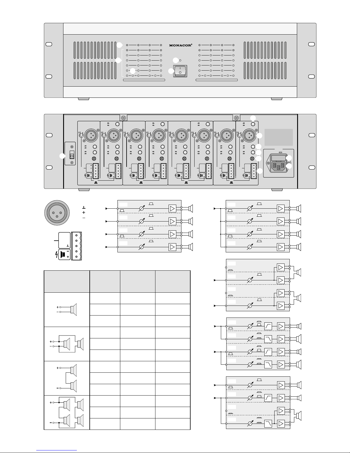
1.1 Frontseite
1
LED CLIP leuchtet bei Übersteuerung des
jeweiligen Kanals und bei Kurzschluss des
entsprechenden Ausgangs
2 LED-Kette zur Pegelanzeige
3
LED BRIDGE leuchtet, wenn der Schalter
für die Betriebsart (7) des entsprechenden
Kanal paares gedrückt ist
4 Betriebsanzeige
5 Ein-/Ausschalter POWER
1.2 Rückseite
6 GROUNDLIFT-Schalter
Position GND: Signalmasse und Gehäuse-
masse sind verbunden
Position LIFT : Signalmasse und Gehäuse-
masse sind getrennt
7
Betriebsart-Schalter für das jeweilige Kanalpaar
Schalter gedrückt: Brückenbetrieb
nicht gedrückt: Normalbetrieb
8
Eingangsbuchsen INPUT als XLR-Buchsen für
Geräte mit Line-Pegel
(Kontaktbelegung siehe Abb. 3)
9 Wahlschalter für die Filterart je Kanal
Schalter gedrückt: Tiefpassfilter (LO-PASS)
nicht gedrückt: Hochpassfilter (HI-PASS)
10
Schalter zum Aktivieren / Deaktivieren des
Filters für den jeweiligen Kanal
Schalter gedrückt: Filter ein (FILTER)
nicht gedrückt: Filter aus (BYPASS)
11 Lautstärkeregler für den jeweiligen Kanal
12 Steckschraubklemmen* für den jeweiligen
Kanal (Kontaktbelegung siehe auch Abb. 4)
Kontakte 1 bis 3:
alternativer Eingang INPUT, direkt verbunden mit dem jeweiligen XLR-Eingang
(8); auch zum Durchschleifen zu den Eingangsklemmen anderer Kanäle geeignet
Kontakte 4 und 5:
Lautsprecheranschlüsse OUTPUT
13
Sicherungshalter; eine durchgebrannte Sicherung nur durch eine gleichen Typs ersetzen
14 Netzbuchse zur Stromversorgung
an 230 V/ 50 Hz
2 Hinweise für den
sicherenGebrauch
Das Gerät entspricht allen relevanten Richtlinien
der EU und trägt deshalb das -Zeichen.
WARNUNG Das Gerät wird mit lebensgefähr-
licher Netzspannung versorgt.
Nehmen Sie deshalb niemals selbst
Eingriffe am Gerät vor und stecken
Sie nichts durch die Lüftungsöffnungen! Es besteht die Gefahr
eines elektrischen Schlages.
Im Betrieb liegt an den Lautsprecheranschlüssen berührungsgefährliche Spannung an. Alle
Anschlüsse nur bei ausgeschaltetem Gerät vornehmen bzw. verändern.
•
Das Gerät ist nur zur Verwendung im Innenbereich geeignet. Schützen Sie es vor Tropfund Spritzwasser, hoher Luftfeuchtigkeit und
Hitze (zulässiger Einsatztemperaturbereich
0 – 40 °C).
•
Stellen Sie keine mit Flüssigkeit gefüllten Gefäße, z. B. Trinkgläser, auf das Gerät.
•
Die in dem Gerät entstehende Wärme muss
durch Luftzirkulation abgegeben werden.
Decken sie darum die Lüftungsöffnungen
niemals ab.
•
Nehmen Sie das Gerät nicht in Betrieb bzw.
ziehen Sie sofort den Netzstecker aus der
Steckdose:
1.
wenn sichtbare Schäden am Gerät oder an
der Netzanschlussleitung vorhanden sind,
2.
wenn nach einem Sturz oder Ähnlichem
der Verdacht auf einen Defekt besteht,
3. wenn Funktionsstörungen auftreten.
Lassen Sie das Gerät in jedem Fall in einer
Fachwerkstatt reparieren.
•
Ziehen Sie den Netzstecker nie am Kabel aus
der Steckdose, fassen Sie immer am Stecker
an.
•
Verwenden Sie für die Reinigung nur ein trockenes, weiches Tuch, niemals Wasser oder
Chemikalien.
•
Wird das Gerät zweckentfremdet, nicht richtig angeschlossen, falsch bedient oder nicht
fachgerecht repariert, kann keine Haftung für
daraus resultierende Sach- oder Personenschäden und keine Garantie für das Gerät
übernommen werden.
Soll das Gerät endgültig aus dem Betrieb genommen werden, übergeben
Sie es zur umweltgerechten Entsorgung
einem örtlichen Recyclingbetrieb.
3 Einsatzmöglichkeiten
Der PA-Mehrkanal-Verstärker ist vielseitig einsetzbar, z. B. auf der Bühne, in der Disco oder in
der Gastronomie. Der Verstärker hat vier (STA-
1504), sechs (STA-1506) oder acht (STA-1508)
getrennte Kanäle, die sich zur Erhöhung der
Ausgangsleistung auch paarweise im Brückenbetrieb zusammenfassen lassen. Für jeden Kanal
einzeln nutzbare Hoch- oder Tiefpassfilter erlauben eine Verwendung als 2-Wege-System ohne
zusätzliche Frequenzweiche. Umfang reiche
Schutzschaltungen schützen den Verstärker und
die angeschlossenen Lautsprecher.
Auf Seite 3 sind fünf Beispiele für die vielseitige
Einsetzbarkeit gezeigt:
Abb. 6: Unabhängiger Betrieb von 4 Kanälen
mit 4 verschiedenen Eingangssignalen.
Abb. 7: Kanalgruppe, bei der das Eingangssig-
nal des ersten Kanals auf die Eingänge
der anderen Kanäle durchgeschleift
wird; für jeden Kanal lässt sich unabhängig die Lautstärke einstellen
Abb. 8: Zusammenfassen von Kanalpaaren
im Brückenbetrieb zur Erhöhung der
Ausgangsleistung
Abb. 9: Aufteilung zweier Eingangssignale in
je zwei Frequenzbereiche für die getrennte Ansteuerung von Hochmitteltonlautsprechern (HIGH) und Tieftonlautsprechern (LOW) mit getrennter
Lautstärkeregelung aller Ausgänge
Abb. 10: Eine Kombinationsmöglichkeit aus
den zuvor gezeigten Konfigurationen,
z. B. für einen PA-Ausgang und einen
Monitorweg: Signal B steuert über den
Kanal CH2 einen Hochmitteltonlautsprecher an; der Tieftonanteil, der in
der Regel eine größere Verstärkerleistung erfordert, wird von den Kanälen
CH3 und CH4 im Brückenbetrieb verstärkt. Signal A wird unabhängig über
Kanal CH1 verstärkt.
Dies sind nur einige Beispiele für die Konfigurationsmöglichkeiten des Verstärkers. Besonders
bei den Modellen mit 6 oder 8 Kanälen sind
noch zahlreiche andere Kombinationen möglich.
4 Aufstellmöglichkeiten
Der Verstärker ist für den Einschub in ein Rack
(482 mm / 19”) vorgesehen, kann aber auch als
Tischgerät verwendet werden. In jedem Fall
muss Luft ungehindert durch alle Lüftungsschlitze strömen können, damit eine ausreichende Kühlung gewährleistet ist.
4.1 Rackeinbau
Für die Rackmontage werden 3 HE (Höheneinheiten) = 133 mm benötigt. Dabei sollte jedoch
ober- und unterhalb des Verstärkers zusätzlich
Platz frei bleiben, damit eine ausreichende Belüftung sichergestellt ist.
Damit das Rack nicht kopflastig wird, muss
der Verstärker im unteren Bereich des Racks eingeschoben werden. Für eine sichere Befestigung
reicht die Frontplatte allein nicht aus. Zusätzlich
müssen Seitenschienen oder eine Bodenplatte
das Gerät halten.
5 Verstärker anschließen
Alle Anschlüsse dürfen nur bei ausgeschaltetem
Gerät hergestellt werden!
5.1 Eingänge
An die XLR-Buchsen INPUT (8) oder Steckschraubklemmen* (12) den Ausgang eines Vorverstärkers oder eines Mischpultes anschließen.
Beide Anschlüsse sind für symmetrische Signale
beschaltet; die Kontaktbelegungen sind in Abbildung 3 und 4 dargestellt. Es kann auch ein
Eingangssignal, was in die XLR-Buchse (8) eines
Kanals eingespeist wird, von den Steckschraubklemmen* (12) desselben Kanals abgenommen
* Die Anschlussklemmen lassen sich zur besseren Hand-
habung von ihrer Steckverbindung abziehen.

5
Deutsch
und auf den Eingang eines anderen Kanals
durchgeschleift werden (wie bei den Beispielen
in den Abbildungen 7, 9 und 10). Dazu jeweils
die Kontakte 1 (SIGNAL+) und 2 (SIGNAL−)
der Steckschraubklemmen* der beiden Kanäle
miteinander verbinden. Die Kontakte 3 (GND)
müssen nicht extern verbunden werden, da sie
es intern bereits sind. Das Eingangssignal sollte
Line-Pegel aufweisen. Für eine Vollaussteuerung
des Verstärkers ist ein Eingangssignal von mindestens 0,7 V erforderlich.
Steht am Ausgang der Signalquelle nur ein
asymmetrisches Signal zur Verfügung, kann dieses über einen Adapter an die Eingangsbuchse
INPUT (8) angeschlossen werden. In dem Adapter müssen die XLR-Kontakte 1 und 3 verbunden
sein (z. B. eignen sich die Cinch / XLR-Adapter
NTA-114 und NA-2MPMF von MONACOR).
Beim alternativen Anschluss eines asymmetri
schen Signals an die Steckschraubklemmen* (12)
müssen entsprechend die Kontakte 2 (SIGNAL−)
und 3 (GND) verbunden werden (vgl.Abb.4).
5.2 Lautsprecher
Die größte Ausgangsleistung wird im Normalbetrieb beim Anschluss von 4-Ω-Lautsprechern
erreicht. Es können auch 8-Ω-Lautsprecher
angeschlossen werden, was die Ausgangsleistung aber etwas verringert. Im Brückenbetrieb
wird die größte Ausgangsleistung mit einem
8-Ω-Lautsprecher erreicht. Die erforderliche
Nennbelastbarkeit (P
min
) der Lautsprecher ist in
der Tabelle Abb. 5 aufgeführt.
An die Kontakte 4 und 5 der Steckschraubklemmen* (12) entsprechend Abb.4 die Lautsprecher anschließen.
Für den Brückenbetrieb, wie am Gerät angegeben, den Pluspol des Lautsprechers mit
der Plusklemme des einen Ausgangs und den
Minus pol des Lautsprechers mit der Plusklemme
des anderen Ausgangs des jeweiligen Kanalpaares verbinden. (Die Plusklemme eines Ausgangs
eines Kanalpaares wird durch die Signalinvertierung im Brückenbetrieb zum Minuspol für den
Lautsprecher.)
Beim Anschluss der Lautsprecher ist auf
die gleiche Polung aller Lautsprecher zu achten. Kommt es jedoch, wenn mehrere Kanäle
dasselbe Signal verstärken, an der Hörposition
zu Phasenauslöschungen, die nicht durch Korrigieren der Lautsprecherpositionen behoben
werden können, kann es erforderlich sein, einzelne Lautsprecher umzupolen.
In der Tabelle Abb. 5 sind auch Anschlussmöglichkeiten für mehrere Lautsprecher an
einem Ausgang aufgeführt. Dazu ist jeweils angegeben, welche Nennbelastbarkeit (P
min
) jeder
Lautsprecher bei entsprechender Impedanz (Z)
mindestens haben muss.
Beim Zusammenschalten von mehreren
Lautsprechern ist besonders auf die richtige
Verbindung der Plus- und Minusanschlüsse zu
achten und dass die Gesamtimpedanz je Ausgang im Normalbetrieb mindestens 4 Ω, im Brückenbetrieb mindestens 8 Ω beträgt.
5.3 Stromversorgung
Das Netzkabel in die Netzbuchse (14) stecken.
Den Netzstecker des Anschlusskabels in eine
Steckdose (230 V/ 50 Hz) stecken. Vor dem ersten Einschalten die Regler LEVEL (11) ganz nach
links drehen.
Änderungen vorbehalten.
6 Bedienung
6.1 Betriebsart wählen
Mit dem Schalter NORMAL / BRIDGE (7) wird
für jedes Kanalpaar die gewünschte Betriebsart
gewählt:
6.1.1 Normalbetrieb
Ist der Schalter ausgerastet [die LED BRIDGE
(3) zwischen den Kanälen des entsprechenden
Kanal paares leuchtet nicht], werden diese beiden Kanäle unabhängig voneinander betrieben.
6.1.2 Brückenbetrieb
Ist der Schalter hineingedrückt [die LED BRIDGE
(3) zwischen den Kanälen des entsprechenden
Kanalpaares leuchtet], wird das Eingangssignal vom zweiten Kanal zusätzlich invertiert auf
den ersten Kanal des Kanalpaares geschaltet.
Dadurch verdoppelt sich die Spannung am Ausgang, wenn der Lautsprecher, wie in Kapitel 5 beschrieben, für den Brückenbetrieb angeschlossen
ist. Ein Eingangssignal am ersten Kanal des Paares
wird ignoriert. Die Lautstärkeeinstellung mit dem
Regler LEVEL (11) und die Filtereinstellungen mit
den Schaltern 9 und 10 (mehr dazu in Kapitel 6.2)
werden nur am zweiten Kanal des Kanalpaares
vorgenommen. Eine Anwendung des Brückenbetriebes zeigen die Beispiele in Abb. 8 und 10.
6.2 Filter
Jeder Kanal verfügt über ein zuschaltbares
Filter mit wählbarer Hochpass- oder TiefpassCharakteristik. Dadurch lassen sich mit diesem Verstärker 2-Wege-Systeme aufbauen, in
denen Hochmitteltonlautsprecher über Kanäle
mit Hochpassfilter und Tieftonlautsprecher über
Kanäle mit Tiefpassfilter betrieben werden.
Bei gedrücktem Schalter FILTER / BYPASS (10)
ist das Filter aktiv. Mit dem Schalter HI-PASS /
LO-PASS (9) wählen, ob das Filter als Hochpass
(Schalter ausgerastet) oder Tiefpass (Schalter
hineingedrückt) dienen soll. Eine Anwendung
der Filter zeigen die Beispiele in den Abbildungen 9 und 10.
6.3 Ein /-Ausschalten
Zur Vermeidung von lauten Schaltgeräuschen
den Endverstärker in einer Verstärkeranlage
immer nach allen anderen Geräten einschalten
und ihn nach dem Betrieb als erstes Gerät wieder
ausschalten. Den Verstärker mit dem Schalter
POWER (5) einschalten. Die Betriebsanzeige (4)
leuchtet. Nach dem Einschalten ist für wenige
Sekunden die Einschaltverzögerung zum Schutz
der Lautsprecher aktiviert.
6.4 Pegel einstellen
Den Ausgang des Mischpultes oder Vorverstärkers auf seinen Nennpegel (0 dB) oder das
größte unverzerrte Ausgangssignal aussteuern.
Die Regler LEVEL (11) so weit aufdrehen, bis
die maximal gewünschte Lautstärke erreicht ist.
Zeigen die LEDs CLIP (1) die Übersteuerung des
Verstärkers an, die Regler der entsprechenden
Kanäle etwas zurückdrehen.
VORSICHT Stellen Sie die Lautstärke am Ver-
stärker nie sehr hoch ein. Hohe
Lautstärken können auf Dauer
das Gehör schädigen! Das Ohr gewöhnt sich an große Lautstärken und empfindet sie nach einiger Zeit als nicht mehr so
hoch. Darum eine hohe Lautstärke nach der
Gewöhnung nicht weiter erhöhen.
6.5 Groundlift-Schalter
Ist ohne ein Musiksignal ein störendes Brummen
zu hören, kann eine Masseschleife die Ursache
sein. Masseschleifen können entstehen, wenn
zwei Geräte sowohl über die Signalmasse als
auch über den Schutzleiter der Stromversorgung
oder eine leitende Verbindung der Gehäuse im
Rack Kontakt haben. Um die so entstandene
Masseschleife aufzutrennen, den Groundlift-Schalter (6) auf Position LIFT stellen.
7 Schutzschaltungen
Die Schutzschaltungen sollen Beschädigungen
der Lautsprecher und des Verstärkers verhindern.
Der eingebaute Pegelbegrenzer (Limiter) regelt
das Eingangssignal zurück, wenn der Grenzpegel
am Ausgang erreicht wird. Dadurch lassen sich
bei Übersteuerung des Verstärkers Verzerrungen vermeiden, die die Lautsprecher schädigen
könnten. Von einer zusätzlichen Schutzschaltung werden die Lautsprecher abgeschaltet:
1. wenige Sekunden lang nach dem Einschalten
(Einschaltverzögerung)
2. wenn der Verstärker überhitzt ist
3. wenn eine Gleichspannung am Ausgang
auftritt
Tritt an einem Lautsprecherausgang ein Kurzschluss auf, leuchtet die CLIP LED (1) des
entsprechenden Kanals. Ist dies der Fall oder
werden die Lautsprecher während des Betriebs
abgeschaltet oder nach dem Einschalten nicht
freigeschaltet, muss der Verstärker ausgeschaltet
und die Fehlerursache behoben werden.
Technische Daten STA-1504 STA-1506 STA-1508
Ausgangsleistung (Sinusleistung)
Normalbetrieb 4 Ω / 8 Ω
Brückenbetrieb 8 Ω
4 × 160 W / 100 W
2 × 320 W
6 × 160 W / 100 W
3 × 320 W
8 × 160 W / 100 W
4 × 320 W
Eingangsempfindlichkeit für Vollaussteuerung an 4 Ω
Eingangsimpedanz
0,7 V
20 kΩ
0,7 V
20 kΩ
0,7 V
20 kΩ
Frequenzbereich
Filter-Trennfrequenz
12 – 60 000 Hz, −1,5 dB
240 Hz
12 – 60 000 Hz, −1,5 dB
240 Hz
12 – 60 000 Hz, −1,5 dB
240 Hz
Störabstand
Kanaltrennung
Klirrfaktor
> 80 dB
> 60 dB, 1 kHz
< 0,1 %
> 80 dB
> 60 dB, 1 kHz
< 0,1 %
> 80 dB
> 60 dB, 1 kHz
< 0,1 %
Einsatztemperatur 0 – 40 °C 0 – 40 °C 0 – 40 °C
Stromversorgung
Leistungsaufnahme
230 V/ 50 Hz
max. 1200 VA
230 V/ 50 Hz
max. 1800 VA
230 V/ 50 Hz
max. 2400 VA
Abmessungen (B × H × T)
Gewicht
482 × 132 × 310 mm, 3 HE
16 kg
482 × 132 × 310 mm, 3 HE
17,5 kg
482 × 132 × 310 mm, 3 HE
19 kg
Diese Bedienungsanleitung ist urheberrechtlich für MONACOR ® INTERNATIONAL GmbH & Co. KG geschützt. Eine Reproduktion für eigene kommerzielle Zwecke – auch auszugsweise – ist untersagt.
6
English
Multichannel PA Amplifier
These instructions are intended for experts with
specific knowledge in PA technology. Please read
these operating instructions carefully prior to
operation and keep them for later reference. All
operating elements and connections described
can be found on the fold-out page 3.
1 Operating Elements and
Connections
1.1 Front panel
1 LED CLIP lights up if the respective channel
is overloaded and in case of short circuit of
the respective output
2 LED row for level indication
3 LED BRIDGE lights up when the switch for
the operating mode (7) of the corresponding
channel pair is pressed
4 POWER LED
5 POWER switch
1.2 Rear panel
6 GROUND LIFT switch
position GND: signal ground and housing
ground are connected
position LIFT: signal ground and housing
ground are separated
7
Operating mode switch for the respective
channel pair
switch pressed: bridge operation
not pressed: normal operation
8 INPUT jacks as XLR jacks for units with line
level (contact configuration see fig. 3)
9
Selector switches for the filter mode of each
channel
switch pressed: low pass filter (LO-PASS)
not pressed: high pass filter (HI-PASS)
10
Switches for activating / deactivating the filter
for the respective channel
switch pressed: filter on (FILTER)
not pressed: filter off (BYPASS)
11 Volume control for the respective channel
12 Plug-in screw terminals* for the respective
channel (contact configuration also see
fig.4)
contacts 1 to 3:
alternative INPUT, directly connected to
the respective XLR input (8); also suitable for feeding the signal through to the
input terminals of other channels
contacts 4 and 5:
speaker connections OUTPUT
13 Fuse holder; only replace a blown fuse by
one of the same type
14 Mains jack for power supply for connection
to 230 V/ 50 Hz
2 Safety Notes
This unit corresponds to all relevant directives of
the EU and is therefore marked with .
WARNING The unit is supplied with hazard-
ous mains voltage. Never make
any modifications on the unit and
do not insert anything through
the air vents! This may cause an
electric shock.
There is a hazard of contact at the speaker
connections with a dangerous voltage during
operation. All connections must only be made
or changed with the unit switched off.
•
The unit is suitable for indoor use only. Protect
it against dripping water and splash water,
high air humidity, and heat (admissible ambient temperature range 0 – 40 °C).
•
Do not place any vessels filled with liquid, e. g.
drinking glasses, on the unit.
•
The heat being generated in the unit must be
carried off by air circulation. Therefore, the air
vents at the housing must not be covered.
•
Do not set the unit into operation, or immediately disconnect the mains plug from the
mains socket if
1.
there is visible damage to the unit or to
the mains cable,
2. a defect might have occurred after a drop
or similar accident,
3. malfunctions occur.
The unit must in any case be repaired by
skilled personnel.
•
Never pull the mains cable to disconnect the
mains plug from the mains socket, always
seize the plug.
•
For cleaning only use a dry, soft cloth, by no
means chemicals or water.
•
No guarantee claims for the unit and no liability for any resulting personal damage or material damage will be accepted if the unit is used
for other purposes than originally intended, if
it is not correctly connected, operated, or not
repaired in an expert way.
If the unit is to be put out of operation
definitively, take it to a local recycling
plant for a disposal which will not be
harmful to the environment.
3 Applications
The PA multichannel amplifier is suitable for
versatile applications, e. g. on stage, in the discothèque, or in the catering trade. The amplifier
has four (STA-1504), six (STA-1506), or eight
(STA-1508) separate channels which can also be
combined in pairs in bridge operation to increase
the output power. High pass filters and low pass
filters which can individually be switched for
each channel allow the use as a 2-way system
without additional crossover network. Extensive
protective circuits protect the amplifier and the
connected speakers.
Page 3 shows five examples for versatile applications:
Fig. 6: Independent operation of four chan-
nels with four different input signals.
Fig. 7: Channel group of which the input sig-
nal of the first channel is fed through
to the inputs of the other channels; the
volume can independently be adjusted
for each channel
Fig. 8: Combination of channel pairs in bridge
operation to increase the output
power
Fig. 9: Division of two input signals in two fre-
quency ranges each for separately driv
ing mid-high range speakers (HIGH)
and bass speakers (LOW) with separate
volume control of all outputs
Fig. 10: A combination possibility of the con-
figurations shown before, e. g. for a
PA output and a monitor way: signal
B drives a mid-high range speaker via
channel CH2; the bass part which
generally requires a higher amplifier
power is amplified by channels CH3
and CH4 in bridge operation. Signal A
is independently amplified via channel
CH1.
These are only some examples for the configuration possibilities of the amplifier. Numerous
other combinations are possible, especially for
the 6-channel or 8-channel models.
4 Installaton
The amplifier is designed to be mounted into a
rack (482 mm / 19”), but it may also be used as
a table top unit. In any case air must be allowed
to move freely through all air vents so that a
sufficient cooling is ensured.
4.1 Rack installation
For the rack mounting 3 rack spaces = 133 mm
are required. Additional space should remain
above and below the amplifier in order to ensure
sufficient ventilation.
In order to prevent that the rack becomes
top-heavy, the amplifier has to be mounted in
the lower part of the rack. The front plate alone
is not sufficient as a secure fastening. The unit
has to be additionally supported by side rails or
a bottom carrier plate.
5 Connecting the Amplifier
All connections must only be made if the unit
is switched off!
5.1 Inputs
Connect the output of a preamplifier or mixer
to the XLR jacks INPUT (8) or plug-in screw terminals* (12). Both connections are designed for
balanced signals; the contact configurations are
shown in figures 3 and 4. It is also possible to
pick up an input signal which is fed to the XLR
jack (8) of a channel from the plug-in screw
terminals* (12) of the same channel and to feed
it through to the input of another channel (as
in case of examples in figures 7, 9, and 10). For
this purpose connect in each case the contacts 1
(SIGNAL+) and 2 (SIGNAL−) of the plug-in screw
terminals* of both channels with each other. The
contacts 3 (GND) must not be connected externally as they are already internally connected.
The input signal should have line level. For rated
power of the amplifier an input signal of 0.7 V
is required as a minimum.
If only an unbalanced signal is available at
the output of the signal source, it can be con-
* For better handling, the connection terminals can be
removed from their plug-in connection.
 Loading...