

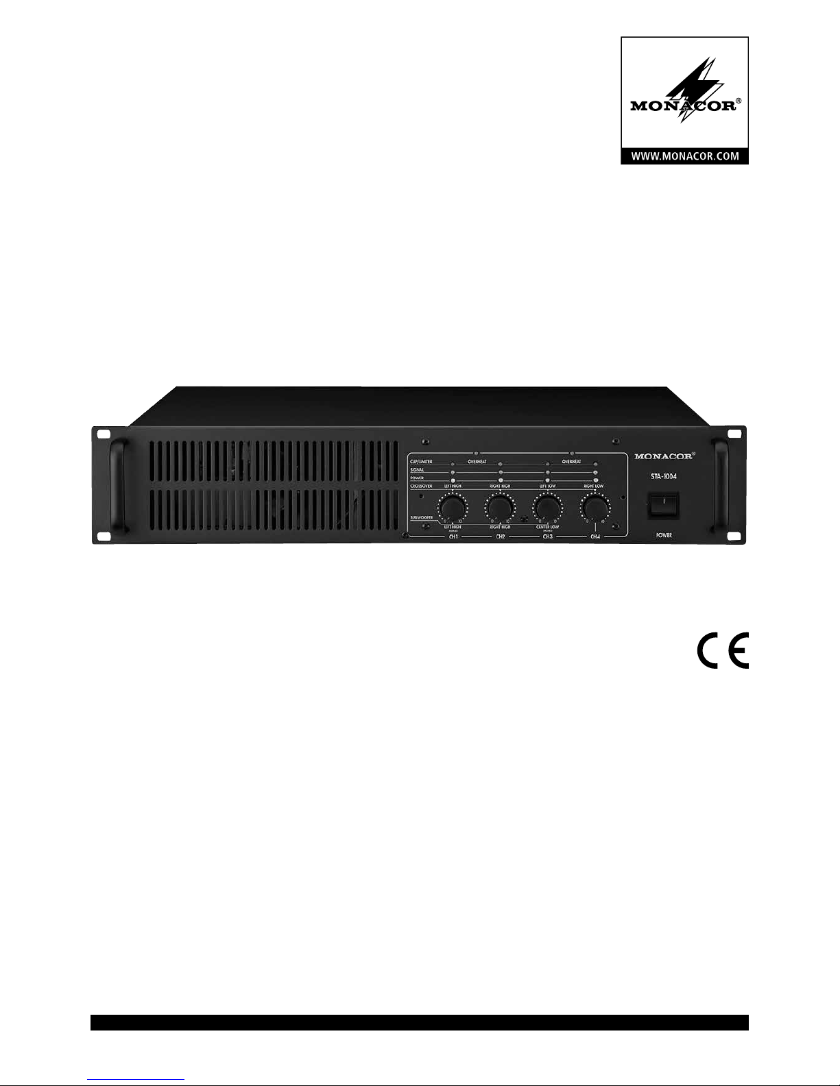
Monacor STA-1004 Instruction Manual
ELECTRONICS FOR SPECIALISTS ELECTRONICS FOR SPECIALISTS ELECTRONICS FOR SPECIALISTS ELECTRONICS FOR SPECIALISTS
BEDIENUNGSANLEITUNG
INSTRUCTION MANUAL
MODE D’EMPLOI
ISTRUZIONI PER L’USO
GEBRUIKSAANWIJZING
MANUAL DE INSTRUCCIONES
INSTRUKCJA OBSŁUGI
SIKKERHEDSOPLYSNINGER
SÄKERHETSFÖRESKRIFTER
TURVALLISUUDESTA
4-Kanal-PA-Verstärker
4-Channel PA Amplifier
STA-1004
Bestell-Nr. • Order No. 24.3160

2
Deutsch ...........Seite 4
English ............Page 8
Français ...........Page 12
Italiano............Pagina 16
Nederlands ........Pagina 20
Español ...........Página 24
Polski .............Strona 28
Dansk .............Sida 32
Svenska ...........Sidan 32
Suomi.............Sivulta 33
ELECTRONICS FOR SPECIALISTS ELECTRONICS FOR SPECIALISTS ELECTRONICS FOR SPECIALISTS ELECTRONICS FOR SPECIALISTS
3
1
CH 1
1
2
CH 2
2
3
CH 3
3
4
CH 4
4
1
CH 1
1
CH 2
2
CH 3
3
CH 4
4
L 1
CH 1
1
R 2
CH 2
2
CH 3
3
CH 4
4
L-1
R-1
L-2
R-2
L 1
CH 1
1
2
R 3
CH 3
3
4
L 1
CH 1
1
R 2
CH 2
2
CH 3
3
CH 4
4
-1
-1
+
-
+
-
L
8 Ω
R
8 Ω
1
CH 1
1
2
CH 3
3
4
-1
-1
+
-
+
-
8 Ω
8 Ω
high
low
high
low
L-high
R-high
L-low
R-low
L 1
CH 1
1
R 2
CH 2
2
CH 3
3
4
high
low
high
low
L-high
R-high
-1
+
-
Subwoofer
8 Ω
+1
OVERHEAT
CLIP/LIMITER
SIGNAL
POWER
LEFT LOW RIGHT LOWLEFT HIGH RIGHT HIGH
CENTER LOWLEFT HIGH RIGHT HIGH
CROSSOVER
CH2
OVERHEAT
MONO
MONO
0
10
0
10
0
10
0
10
SUBWOOFER
50 2k5
55
70
110
250
700
1k3
1k8
Hz
STEREO
BRIDGE
3+4
SOLO
1
L-HI
L-LO
CROSSOVER
R-HI
R-LO
R-HI L-HI
LOW
SOLO
2
CROSSOVER
SUBWOOFER
230V~ /50Hz
CH1
CH2
CH4
CH3
ON
OFF
CH 1
STEREO
BRIDGE
1+2
MODE AMODE B
SOLO
1
SUBWOOFER/
CROSSOVER
OTHER
CROSSOVER
FREQUENCY
BRIDGE MONO
CROSSOVER / SUB LEFT
LINK 1+2LINK 1+3LINK 2+4
PEAK LIMITER
BALANCED
(UNBAL.)
BALANCED
(UNBAL.)
BALANCED
(UNBAL.)
BALANCED
(UNBAL.)
CH 2CH 3
CH 4
L-HI
L-LO
CH 4
4 Ω / 250 W MIN. LOAD
CH 3
4 Ω / 250 W MIN. LOAD8 Ω / 500 W
MIN. LOAD
BRIDGE
CH 1
4 Ω / 250 W MIN. LOAD
CH 3 CH 4CH1
BRIDGE MONO CROSSOVER / SUB LEFT
POWER
STA-1004
CH 2
4 Ω / 250 W MIN. LOAD
BRIDGE
8 Ω / 500 W
MIN. LOAD
1
6
1098
7
2 3 4 5
11 12 13 14
➀
➃
Kanalgruppe
Channel group
➄
Stereo-Parallelbetrieb
Stereo parallel operation
➅
Stereo-Brückenbetrieb
Stereo bridge operation
➆
Mono-Brückenbetrieb
Mono bridge operation
➈
Tri-Mode
➇
Bi-Amping
➂
Einzelbetrieb
Indivdual operation
➁
1
CH 1
DE Eingang Filter Pegelregler Endstufe Lautsprecher
GB input crossover level control power amplifier speaker
FR entrée filtre réglage de niveau amplificateuer (étage final) haut-parleur
IT ingresso filtro regolatore livello amplificatore di potenza altoparlante
NL ingang filter niveauregelaar uitgangstrap luidspreker
ES entrada filtro reglaje de nivel amplificador de potencia altavoz
PL wejście zwrotnica regulator poziomu końcówka mocy głośnik
4
Deutsch
4-Kanal-PA-Verstärker
Diese Anleitung richtet sich an Fachleute, die entsprechende Kenntnisse
in der Lautsprecher- und Beschallungstechnik besitzen. Bitte lesen Sie die
Anleitung vor der Installation gründlich durch und heben Sie sie für ein
späteres Nachlesen auf. Auf der ausklappbaren Seite 3 finden Sie alle
beschriebenen Bedienelemente und Anschlüsse.
1 Übersicht der Bedienelemente und Anschlüsse
1.1 Frontseite
1 LED OVERHEAT, leuchtet bei Überhitzung der Kanäle 1 und 2
2 LED OVERHEAT, leuchtet bei Überhitzung der Kanäle 3 und 4
3 LEDs CLIP/ LIMITER
Limiter eingeschaltet: LED leuchtet, wenn der Limiter die Lautstärke
des entsprechenden Kanals reduziert
Limiter ausgeschaltet: LED leuchtet bei Übersteuerung des entspre-
chenden Kanals
4
LEDs SIGNAL, leuchten, wenn das Ausgangssignal des entsprechenden
Kanals größer als 100 mW ist
5 Betriebsanzeigen POWER
6
Pegelregler, die Funktionen der Regler hängen von der gewählten
Betriebsart ab, siehe Tabelle 1
7 Ein-/Ausschalter POWER
Tabelle 1 Funktion der Pegelregler CH 1 … CH 4
Abb.
Modus
Regler
CH 1 CH 2 CH 3 CH 4
3 Einzelbetrieb Kanal 1 Kanal 2 Kanal 3 Kanal 4
4 Kanalgruppe Kanal 1 Kanal 2 Kanal 3 Kanal 4
5 Stereo, parallel
Lautsprecher
links 1
Lautsprecher
rechts 1
Lautsprecher
links 2
Lautsprecher
rechts 2
6 Stereo-Brücke linker Kanal – rechter Kanal –
7 Mono-Brücke Lautsprecher 1 – Lautsprecher 2 –
8 Bi-Amping
MittelhochtonLautsprecher L
MittelhochtonLautsprecher R
Basslautsprecher
links
Basslautsprecher
rechts
9 Tri-Mode
MittelhochtonLautsprecher L
MittelhochtonLautsprecher R
Subwoofer –
– = Regler ohne Funktion
1.2 Rückseite
8
Schalter zum Einstellen der verschiedenen Betriebsarten, siehe Tabelle 2
9 Regler zum Einstellen der Trennfrequenz
Der Regler ist nur in den Betriebsarten Bi-Amping und Tri-Mode
wirksam.
10 Schalter für die Limiter-Funktion
11 Netzkabel zum Anschluss an 230 V/50 Hz
12 Eingänge über XLR-Buchsen, symmetrisch
13 Eingänge über 6,3-mm-Klinkenbuchsen, asymmetrisch
14 Ausgänge zum Anschluss der Lautsprecher
Tabelle 2 Wahl der Betriebsart
Abb.
Modus
Schalter
LINK 2 + 4 MODE B LINK 1 + 3
SUBWOOFER /
CROSSOVER
LINK 1 + 2 MODE A
3 Einzelbetrieb
SOLO STEREO SOLO
OTHER SOLO STEREO
4 Kanalgruppe
2 STEREO 1
OTHER
1 STEREO
5 Stereo, parallel
2 STEREO 1
OTHER SOLO STEREO
6 Stereo-Brücke –
BRIDGE 3+4 SOLO
OTHER
–
BRIDGE 1+2
7 Mono-Brücke –
BRIDGE 3+4 1
OTHER
–
BRIDGE 1+2
8 Bi-Amping – – –
CROSSOVER
– –
9 Tri-Mode – – –
SUBWOOFER
– –
= Schalter nicht gedrückt, Schalter hineingedrückt, – = Schalter ohne Funktion
2 Hinweise für den
sicherenGebrauch
Das Gerät entspricht allen relevanten Richtlinien
der EU und trägt deshalb das -Zeichen.
WARNUNG
Das Gerät wird mit lebensgefähr licher Netzspannung versorgt.
Nehmen Sie deshalb niemals
selbst Eingriffe am Gerät vor
und stecken Sie nichts durch die
Lüftungs öffnungen! Es besteht
die Gefahr eines elektrischen
Schlages.
•
Das Gerät ist nur zur Verwendung im Innenbereich geeignet. Schützen Sie es vor Tropfund Spritzwasser, hoher Luftfeuchtigkeit und
Hitze (zulässiger Einsatztemperaturbereich
0 – 40 °C).
•
Stellen Sie keine mit Flüssigkeit gefüllten Gefäße, z. B. Trinkgläser, auf das Gerät.
•
Die in dem Gerät entstehende Wärme muss
durch Luftzirkulation abgegeben werden.
Decken sie darum die Lüftungsöffnungen
niemals ab.
•
Nehmen Sie das Gerät nicht in Betrieb bzw.
ziehen Sie sofort den Netzstecker aus der
Steckdose:
1. wenn sichtbare Schäden am Gerät oder an
der Netzanschlussleitung vorhanden sind,
2.
wenn nach einem Sturz oder Ähnlichem der
Verdacht auf einen Defekt besteht,
3. wenn Funktionsstörungen auftreten.
Lassen Sie das Gerät in jedem Fall in einer
Fachwerkstatt reparieren.
•
Ein beschädigtes Netzkabel darf nur durch
eine Fachwerkstatt ersetzt werden.
•
Ziehen Sie den Netzstecker nie am Kabel aus
der Steckdose, fassen Sie immer am Stecker
an.
•
Verwenden Sie für die Reinigung nur ein trockenes, weiches Tuch, niemals Wasser oder
Chemikalien.
•
Wird das Gerät zweckentfremdet, nicht richtig angeschlossen, falsch bedient oder nicht
fachgerecht repariert, kann keine Haftung für
daraus resultierende Sach- oder Personenschäden und keine Garantie für das Gerät
übernommen werden.
Soll das Gerät endgültig aus dem Betrieb genommen werden, übergeben
Sie es zur umweltgerechten Entsorgung
einem örtlichen Recyclingbetrieb.
3 Einsatzmöglichkeiten
Dieser Verstärker mit einer Spitzenleistung von
1400 W ist speziell für den Einsatz auf der Bühne
und in der Diskothek konzipiert. Umfangreiche
Schutzschaltungen schützen den Verstärker und
die angeschlossenen Lautsprecher.
Der Verstärker kann vier Breitbandlautsprecher antreiben. Durch die integrierte Frequenzweiche lässt sich auch ein aktives Zweiwegesystem mit zwei Mittelhochtönern und
zwei Basslautsprechern bzw. einem Subwoofer
realisieren. Um eine größere Ausgangsleistung
zu erhalten, können die Kanäle 1, 2 und / oder 3,
4 im Brückenbetrieb jeweils einen Lautsprecher
antreiben.
4 Aufstellmöglichkeiten
Der Verstärker ist für den Einschub in ein Rack
(482 mm / 19”) vorgesehen, kann aber auch als
Tischgerät verwendet werden. In jedem Fall muss
die Luft ungehindert durch alle Lüftungsschlitze
strömen können, damit eine ausreichende Kühlung gewährleistet ist.
4.1 Rackeinbau
Für die Rackmontage werden 2 HE (2 Höheneinheiten = 89 mm) benötigt.
Damit das Rack nicht kopflastig wird, muss
der Verstärker im unteren Bereich des Racks eingeschoben werden. Für eine sichere Befestigung
reicht die Frontplatte allein nicht aus. Zusätzlich muss der Verstärker über die rückseitigen
Befestigungslaschen mit dem Rack verschraubt
werden.
Die vom Verstärker ausgeblasene, erhitzte
Luft muss aus dem Rack nach hinten oder oben
austreten können. Andernfalls kommt es im
Rack zu einem Hitzestau, wodurch nicht nur
der Verstärker, sondern auch weitere Geräte beschädigt werden können. Bei unzureichendem
Wärmeabfluss in das Rack über dem Verstärker
eine Lüftereinheit einsetzen.
5
Deutsch
5 Verstärker anschließen
Vorsicht!
Alle Anschlüsse sollten nur durch eine qualifizierte Fachkraft und unbedingt bei ausgeschaltetem Verstärker vorgenommen werden.
Die Isolationsstifte nicht aus den unbenutzten
Ausgangsbuchsen (14) entfernen. Dadurch
wird ein elektrischer Schlag bei versehentlicher
Berührung vermieden.
Der Anschluss der Eingänge und der Lautsprecher ist vom gewählten Betriebsmodus abhängig. Darum vor dem Herstellen der Anschlüsse
den Betriebsmodus auswählen, der für die jeweilige Anwendung optimal ist. Die verschiedenen
Modi sind in den Abb. 3 – 9 dargestellt.
Hinweis: Bei der Wahl der Eingangsbuchsen sollten die
XLR-Eingänge (12) bevorzugt werden, weil eine symmetrische Signalübertragung die beste Störunterdrückung,
besonders bei langen Verbindungskabeln, bietet. Sind
die Ausgänge der Signalquellen asymmetrisch, diese mit
den 6,3-mm-Klinkenbuchsen (13) verbinden.
5.1 Einzelbetrieb
Im Einzelbetrieb (Abb. 3) wird jede Endstufe von
einem separaten Signal angesteuert. Für diesen
Betriebsmodus alle Schalter (8) auf der Geräterückseite ausrasten:
LINK 2 + 4 MODE B LINK 1 + 3
SUBWOOFER /
CROSSOVER
LINK 1 + 2 MODE A
SOLO STEREO SOLO
OTHER SOLO STEREO
Schalterstellungen für den Einzelbetrieb Tabelle 3
= Schalter nicht gedrückt, = Schalter hineingedrückt
5.1.1 Eingänge
An die Eingangsbuchsen CH 1 bis CH 4 die Line-Signalquellen (z. B. Vorverstärker, Mischpult etc.)
anschließen. Als Eingänge können die XLR- (12)
oder die Klinkenbuchsen (13) verwendet werden.
5.1.2 Ausgänge
Der Verstärker kann vier Lautsprecher bzw. vier
Lautsprechergruppen betreiben. Die größte
Ausgangsleistung wird beim Anschluss von
4-Ω-Lautsprechern und von Lautsprechergruppen mit je einer Gesamtimpedanz von 4 Ω erreicht. Es können jedoch auch 8-Ω-Lautsprecher
bzw. Lautsprechergruppen mit je einer Gesamtimpedanz von 8 Ω angeschlossen werden,
wobei sich die Ausgangsleistung aber etwas verringert. Die Lautsprecher bzw. die Lautsprechergruppen müssen je mit mindestens folgender
Sinusleistung belastbar sein:
4-Ω-Lautsprecher: 250 W
8-Ω-Lautsprecher: 160 W
Die Lautsprecher bzw. Lautsprechergruppen an
die Ausgangsbuchsen (14) anschließen:
CH 1+ = Pluspol Lautsprecher Kanal 1
CH 1− = Minuspol Lautsprecher Kanal 1
CH 2+ = Pluspol Lautsprecher Kanal 2
CH 2− = Minuspol Lautsprecher Kanal 2
CH 3+ = Pluspol Lautsprecher Kanal 3
CH 3− = Minuspol Lautsprecher Kanal 3
CH 4+ = Pluspol Lautsprecher Kanal 4
CH 4− = Minuspol Lautsprecher Kanal 4
5.2 Betriebsart Kanalgruppe
Bei der Betriebsart Kanalgruppe (Abb. 4) werden die vier Endstufen von einem gemeinsamen
Eingangssignal angesteuert. Dazu die Schalter
(8) auf der Geräterückseite wie folgt einstellen:
LINK 2 + 4 MODE B LINK 1 + 3
SUBWOOFER /
CROSSOVER
LINK 1 + 2 MODE A
2 STEREO 1
OTHER
1 STEREO
Schalterstellungen für die Betriebsart Kanalgruppe Tabelle 4
= Schalter nicht gedrückt, = Schalter hineingedrückt
5.2.1 Eingänge
An die Eingangsbuchse CH 1 die Line-Signalquelle (z. B. Vorverstärker, Mischpult etc.) anschließen. Als Eingang kann die XLR- (12) oder
die Klinkenbuchse (13) verwendet werden. Die
Eingänge CH 2, CH 3 und CH 4 werden nicht
angeschlossen.
5.2.2 Ausgänge
Der Verstärker kann vier Lautsprecher bzw. vier
Lautsprechergruppen betreiben. Die größte
Ausgangsleistung wird beim Anschluss von
4-Ω-Lautsprechern und von Lautsprechergruppen mit je einer Gesamtimpedanz von 4 Ω erreicht. Es können jedoch auch 8-Ω-Lautsprecher
bzw. Lautsprechergruppen mit je einer Gesamtimpedanz von 8 Ω angeschlossen werden,
wobei sich die Ausgangsleistung aber etwas verringert. Die Lautsprecher bzw. die Lautsprechergruppen müssen je mit mindestens folgender
Sinusleistung belastbar sein:
4-Ω-Lautsprecher: 250 W
8-Ω-Lautsprecher: 160 W
Die Lautsprecher bzw. Lautsprechergruppen an
die Ausgangsbuchsen (14) anschließen:
CH 1+ = Pluspol Lautsprecher Kanal 1
CH 1− = Minuspol Lautsprecher Kanal 1
CH 2+ = Pluspol Lautsprecher Kanal 2
CH 2− = Minuspol Lautsprecher Kanal 2
CH 3+ = Pluspol Lautsprecher Kanal 3
CH 3− = Minuspol Lautsprecher Kanal 3
CH 4+ = Pluspol Lautsprecher Kanal 4
CH 4− = Minuspol Lautsprecher Kanal 4
5.3 Stereo-Parallelbetrieb
Im Parallel-Betrieb (Abb. 5) erhalten die Kanäle
1 und 3 sowie die Kanäle 2 und 4 jeweils das
gleiche Eingangssignal. Hierzu die Schalter (8)
auf der Geräterückseite wie folgt einstellen:
LINK 2 + 4 MODE B LINK 1 + 3
SUBWOOFER /
CROSSOVER
LINK 1 + 2 MODE A
2 STEREO 1
OTHER SOLO STEREO
Schalterstellungen für den Stereo-Parallelbetrieb Tabelle 5
= Schalter nicht gedrückt, = Schalter hineingedrückt
5.3.1 Eingänge
Den Ausgang der Linequelle (z. B. Mischpult,
Vorverstärker etc.) mit den Eingängen des Verstärkers verbinden:
Den linken Kanal an die Eingangsbuchse CH 1
anschließen und den rechten Kanal an die Eingangsbuchse CH 2. Als Eingänge können die
XLR- (12) oder die Klinkenbuchsen (13) verwendet werden. Die Eingänge CH 3 und CH 4
bleiben frei.
5.3.2 Ausgänge
Der Verstärker kann vier Lautsprecher bzw. vier
Lautsprechergruppen betreiben. Die größte
Ausgangsleistung wird beim Anschluss von
4-Ω-Lautsprechern und von Lautsprechergruppen mit je einer Gesamtimpedanz von 4 Ω erreicht. Es können jedoch auch 8-Ω-Lautsprecher
bzw. Lautsprechergruppen mit je einer Gesamtimpedanz von 8 Ω angeschlossen werden,
wobei sich die Ausgangsleistung aber etwas verringert. Die Lautsprecher bzw. die Lautsprechergruppen müssen je mit mindestens folgender
Sinusleistung belastbar sein:
4-Ω-Lautsprecher: 250 W
8-Ω-Lautsprecher: 160 W
Die Lautsprecher bzw. Lautsprechergruppen an
die Ausgangsbuchsen (14) anschließen:
CH 1+ = Pluspol Lautsprecher links 1
CH 1− = Minuspol Lautsprecher links 1
CH 2+ = Pluspol Lautsprecher rechts 1
CH 2− = Minuspol Lautsprecher rechts 1
CH 3+ = Pluspol Lautsprecher links 2
CH 3− = Minuspol Lautsprecher links 2
CH 4+ = Pluspol Lautsprecher rechts 2
CH 4− = Minuspol Lautsprecher rechts 2
5.4 Stereo-Brückenbetrieb
Bei dieser Betriebsart sind die Kanäle 1 und 2
sowie die Kanäle 3 und 4 in Brücke geschaltet
(Abb. 6) und geben dadurch jeweils eine höhere
Leistung als ein einzelner Kanal ab. Dazu die
Schalter (8) auf der Geräterückseite wie folgt
einstellen:
LINK 2 + 4 MODE B LINK 1 + 3
SUBWOOFER /
CROSSOVER
LINK 1 + 2 MODE A
–
BRIDGE 3+4 SOLO
OTHER
–
BRIDGE 1+2
Schalterstellungen für den Stereo-Brückenbetrieb Tabelle 6
= Schalter nicht gedrückt, = gedrückt, – = ohne Funktion
5.4.1 Eingänge
Den Ausgang der Linequelle (z. B. Mischpult,
Vorverstärker etc.) mit den Eingängen des Verstärkers verbinden:
Den linken Kanal an die Eingangsbuchse CH 1
anschließen und den rechten Kanal an die Eingangsbuchse CH 3. Als Eingänge können die
XLR- (12) oder die Klinkenbuchsen (13) verwendet werden. Die Eingänge CH 2 und CH 4
werden nicht angeschlossen.
5.4.2 Ausgänge
Der Verstärker kann zwei Lautsprecher bzw.
zwei Lautsprechergruppen betreiben. Beim
Brückenbetrieb muss die Impedanz der Lautsprecher bzw. die Gesamtimpedanz der Lautsprechergruppen mindestens 8 Ω und die Belastbarkeit mindestens 500 W Sinus betragen. Die
Lautsprecher bzw. Lautsprechergruppen an die
Ausgangsbuchsen (14) anschließen:
CH 1+ = Pluspol Lautsprecher links
CH 2+ = Minuspol Lautsprecher links
CH 3+ = Pluspol Lautsprecher rechts
CH 4+ = Minuspol Lautsprecher rechts
6
Deutsch
5.5 Mono-Brückenbetrieb
Beim Mono-Brückenbetrieb (Abb. 7) sind die
Kanäle 1 und 2 sowie die Kanäle 3 und 4 in
Brücke geschaltet und geben dadurch jeweils
eine höhere Leistung als ein einzelner Kanal
ab. Außerdem erhalten alle Kanäle das gleiche
Eingangssignal. Dazu die Schalter (8) auf der
Geräterückseite wie folgt einstellen:
LINK 2 + 4 MODE B LINK 1 + 3
SUBWOOFER /
CROSSOVER
LINK 1 + 2 MODE A
–
BRIDGE 3+4 1
OTHER
–
BRIDGE 1+2
Schalterstellungen für den Mono-Brückenbetrieb Tabelle 7
= Schalter ausgerastet, = eingerastet, – = ohne Funktion
5.5.1 Eingänge
An die Eingangsbuchse CH 1 die Line-Signalquelle (z. B. Vorverstärker, Mischpult etc.) anschließen. Als Eingang kann die XLR- (12) oder
die Klinkenbuchse (13) verwendet werden.
Die Eingänge CH 2, CH 3 und CH 4 werden
nicht angeschlossen.
5.5.2 Ausgänge
Der Verstärker kann zwei Lautsprecher bzw.
zwei Lautsprechergruppen betreiben. Beim
Brückenbetrieb muss die Impedanz der Lautsprecher bzw. die Gesamtimpedanz der Lautsprechergruppen mindestens 8 Ω und die Belastbarkeit mindestens 500 W Sinus betragen. Die
Lautsprecher bzw. Lautsprechergruppen an die
Ausgangsbuchsen (14) anschließen:
CH1+ = Pluspol Lautsprecher 1
CH2+ = Minuspol Lautsprecher 1
CH3+ = Pluspol Lautsprecher 2
CH4+ = Minuspol Lautsprecher 2
5.6 Bi-Amping
Bei der Betriebsart Bi-Amping sind die Endstufen
zu einem aktiven 2-Wege-Stereosystem konfiguriert (Abb. 8). Die Mittelhochtöner und die
Basslautsprecher werden dabei getrennt an die
Endstufen angeschlossen. Für diesen Betriebsmodus die Schalter (8) auf der Geräterückseite
wie folgt einstellen:
LINK 2 + 4 MODE B LINK 1 + 3
SUBWOOFER /
CROSSOVER
LINK 1 + 2 MODE A
– – –
CROSSOVER
– –
Schalterstellungen für Bi-Amping Tabelle 8
= Schalter ausgerastet, = eingerastet, – = ohne Funktion
5.6.1 Eingänge
Den Ausgang der Linequelle (z. B. Mischpult,
Vorverstärker etc.) mit den Eingängen des Verstärkers verbinden:
Den linken Kanal an die Eingangsbuchse CH 1
anschließen und den rechten Kanal an die Eingangsbuchse CH 2. Als Eingänge können die
XLR- (12) oder die Klinkenbuchsen (13) verwendet werden. Die Eingänge CH 3 und CH 4
bleiben frei.
5.6.2 Ausgänge
Der Verstärker kann vier Lautsprecher bzw. vier
Lautsprechergruppen betreiben. Die größte
Ausgangsleistung wird beim Anschluss von
4-Ω-Lautsprechern und von Lautsprechergruppen mit je einer Gesamtimpedanz von 4 Ω erreicht. Es können jedoch auch 8-Ω-Lautsprecher
bzw. Lautsprechergruppen mit je einer Gesamtimpedanz von 8 Ω angeschlossen werden,
wobei sich die Ausgangsleistung aber etwas verringert. Die Lautsprecher bzw. die Lautsprechergruppen müssen je mit mindestens folgender
Sinusleistung belastbar sein:
4-Ω-Lautsprecher: 250 W
8-Ω-Lautsprecher: 160 W
Die Lautsprecher bzw. Lautsprechergruppen an
die Ausgangsbuchsen (14) anschließen:
CH 1+ = Pluspol Mittelhochtöner links
CH 1− = Minuspol Mittelhochtöner links
CH 2+ = Pluspol Mittelhochtöner rechts
CH 2− = Minuspol Mittelhochtöner rechts
CH 3+ = Pluspol Basslautsprecher links
CH 3− = Minuspol Basslautsprecher links
CH 4+ = Pluspol Basslautsprecher rechts
CH 4− = Minuspol Basslautsprecher rechts
5.7 Tri-Mode
Im Tri-Mode (Abb. 9) können ein Subwoofer
im Brückenbetrieb und zwei Mittelhochtöner
angetrieben werden. Dazu die Schalter (8) auf
der Geräterückseite wie folgt einstellen:
LINK 2 + 4 MODE B LINK 1 + 3
SUBWOOFER /
CROSSOVER
LINK 1 + 2 MODE A
– – –
CROSSOVER
– –
Schalterstellungen für den Tri-Mode Tabelle 9
= Schalter ausgerastet, = eingerastet, – = ohne Funktion
5.7.1 Eingänge
Den Ausgang der Linequelle (z. B. Mischpult,
Vorverstärker etc.) mit den Eingängen des Verstärkers verbinden:
Den linken Kanal an die Eingangsbuchse CH 1
anschließen und den rechten Kanal an die Eingangsbuchse CH 2. Als Eingänge können die
XLR- (12) oder die Klinkenbuchsen (13) verwendet werden. Die Eingänge CH 3 und CH 4
bleiben frei.
5.7.2 Ausgänge
Der Verstärker kann zwei Mittelhochtöner bzw.
zwei Mittelhochtöner-Gruppen betreiben und
im Brückenbetrieb einen Subwoofer bzw. eine
Subwoofer-Gruppe.
Für die Mittelhochtöner wird die größte Ausgangsleistung beim Anschluss von 4-Ω-Lautsprechern und von Lautsprechergruppen mit
je einer Gesamtimpedanz von 4 Ω erreicht. Es
können jedoch auch 8-Ω-Lautsprecher bzw.
Lautsprechergruppen mit je einer Gesamtimpedanz von 8 Ω angeschlossen werden, wobei
sich die Ausgangsleistung aber etwas verringert.
Die Lautsprecher bzw. die Lautsprechergruppen
müssen je mit mindestens folgender Sinusleistung belastbar sein:
4-Ω-Lautsprecher: 250 W
8-Ω-Lautsprecher: 160 W
Für den Subwoofer bzw. die Subwoofer-Gruppe
muss wegen des Brückenbetriebs die Impedanz
des Lautsprechers bzw. die Gesamtimpedanz der
Lautsprechergruppe mindestens 8 Ω betragen
und die Belastbarkeit mindestens 500 W Sinus.
Die Lautsprecher bzw. Lautsprechergruppen an
die Ausgangsbuchsen (14) anschließen:
CH 1+ = Pluspol Mittelhochtöner links
CH 1− = Minuspol Mittelhochtöner links
CH 2+ = Pluspol Mittelhochtöner rechts
CH 2− = Minuspol Mittelhochtöner rechts
CH 3+ = Pluspol Subwoofer
CH 4+ = Minuspol Subwoofer
5.8 Stromversorgung
Nachdem alle anderen Anschlüsse hergestellt
sind, den Netzstecker des Anschlusskabels (11)
in eine Steckdose (230 V/ 50 Hz) stecken.
6 Bedienung
6.1 Lautstärkebegrenzer (Limiter)
Die vier Endstufen des Verstärkers sind mit je
einem Limiter ausgestattet, der dafür sorgt, dass
beim Aufdrehen der Pegelregler (6) die Lautstärke nach dem Erreichen des maximalen, unverzerrten Pegels nicht weiter ansteigt. Dadurch
werden Verzerrungen bei hohen Lautstärken
vermieden und die angeschlossenen Lautsprecher geschützt.
Der Limiter kann für jede Endstufe separat aus- bzw. eingeschaltet werden. Dazu die
DIP-Schalter PEAK LIMITER (10) bei ausgeschaltetem Verstärker entsprechend einstellen.
6.2 Ein- und Ausschalten
Zur Vermeidung von lauten Schaltgeräuschen
den Verstärker in einer Audio-Anlage immer
nach allen anderen Geräten einschalten und
ihn nach dem Betrieb als erstes Gerät wieder
ausschalten.
1)
Vor dem Einschalten zunächst die Regler
CH 1 bis CH 4 (6) in die Position „0“ stellen.
2) Mit dem Schalter POWER (7) den Verstärker
einschalten. Nach dem Einschalten leuchten
die gelben LEDs POWER (5).
Achtung!
Nach dem Betrieb zuerst alle Pegelregler (6)
in die Position „0“ drehen und mit dem Ausschalten un gefähr 3 Minuten warten, damit der
interne Lüfter die Endstufen herunterkühlen
kann. Anderenfalls kann das Gerät beschädigt
werden.
6.3 Lautstärke einstellen
Je nach eingestelltem Betriebsmodus wird mit
den Pegelreglern CH 1 bis CH 4 (6) die Lautstärke
der angeschlossenen Lautsprecher eingestellt:
Abb. Modus Regler CH 1 Regler CH 2 Regler CH 3 Regler CH 4
3
Einzelbetrieb
Kanal 1 Kanal 2 Kanal 3 Kanal 4
4
Kanal-
gruppe
Kanal 1 Kanal 2 Kanal 3 Kanal 4
5
Stereo,
parallel
Lautspre-
cher L 1
Lautspre-
cher R 1
Lautspre-
cher L 2
Lautspre-
cher R 2
6
StereoBrücke
linker
Kanal
–
rechter
Kanal
–
7
MonoBrücke
Lautspre-
cher 1
–
Lautspre-
cher 2
–
8 Bi-Amping
Mittelhoch-
töner L
Mittelhoch-
töner R
Basslaut-
sprecher L
Basslaut-
sprecher R
9 Tri-Mode
Mittelhoch-
töner L
Mittelhoch-
töner R
Subwoofer –
Funktion der Pegelregler Tabelle 10
– = Regler ohne Funktion
Vorsicht!
Stellen Sie die Lautstärke am Verstärker nie sehr
hoch ein. Hohe Lautstärken können auf Dauer
das Gehör schädigen! Das Ohr gewöhnt sich
an große Lautstärken und empfindet sie nach
einiger Zeit als nicht mehr so hoch. Darum eine
hohe Lautstärke nach der Gewöhnung nicht
weiter erhöhen.
Mit den entsprechenden Pegelreglern die gewünschte Lautstärke einstellen. Ist die Ausgangsleistung größer als 100 mW, leuchtet
die zugehörige grüne Anzeige SIGNAL (4).
Bei Übersteuerung leuchtet die rote Anzeige
CLIP/ LIMITER (3). Dann die Lautstärke mit dem
dazugehörigen Regler reduzieren.
Bei eingeschaltetem Limiter (siehe Kapitel
6.1) leuchtet die rote Anzeige CLIP/ LIMITER,

7
Deutsch
wenn der Limiter die Lautstärke reduziert. Der
entsprechende Pegelregler braucht dann nur
zurückgedreht zu werden, wenn die Anzeige
anhaltend leuchtet.
6.4 Trennfrequenz einstellen
Ist die Betriebsart Bi-Amping oder Tri-Mode eingestellt, muss die Trennfrequenz für die Basslautsprecher bzw. für den Subwoofer eingestellt
werden, d. h. die Frequenz, die die Lautsprecher
noch abstrahlen können (siehe hierzu die technischen Daten der Basslautsprecher bzw. des
Subwoofers). Mithilfe eines Schraubendrehers
den Regler CROSSOVER FREQUENCY (9) auf die
entsprechende Frequenz einstellen.
6.5 Schutz vor Manipulation
Damit die vorgenommenen Einstellungen nicht
versehentlich oder mutwillig geändert werden
können, liegen dem Gerät eine Abdeckung für
die Regler (6) auf der Frontseite sowie eine Abdeckung für die Schalter (8) und den Regler (9)
auf der Rückseite bei. Mit den dazugehörigen
Schrauben lassen sich diese Abdeckungen über
den Bedienelementen befestigen.
7 Schutzschaltung
Zum Schutz der Endstufen des Verstärkers und
der angeschlossenen Lautsprecher sind Schutzschaltungen vorhanden, die in folgenden Fällen
ansprechen:
– bei Überlast oder Kurzschluss an den Aus-
gängen
– bei Überhitzung des Verstärkers
Bei Überhitzung der Kanäle 1 und 2 leuchtet
die linke Anzeige OVERHEAT (1) und die beiden
Endstufen werden abgeschaltet. Sind nur die
Kanäle 1 und 2 überhitzt, arbeiten die Kanäle
3 und 4 weiter.
Bei Überhitzung der Kanäle 3 und 4 leuchtet
die rechte Anzeige OVERHEAT (2) und die beiden
Endstufen werden abgeschaltet. Sind nur die
Kanäle 3 und 4 überhitzt, arbeiten die Kanäle
1 und 2 weiter.
Zum weiteren Betrieb muss die Ausgangsleistung reduziert oder der Verstärker besser belüftet werden. Nachdem die entsprechenden
Kanäle auf normale Betriebstemperatur abgekühlt sind, arbeiten sie weiter.
8 Technische Daten
Ausgangsleistung
4-Ω-Betrieb: . . . . . . . .4 × 250 W Sinus
8-Ω-Betrieb: . . . . . . . .4 × 160 W Sinus
8-Ω-Brückenbetrieb: . .2 × 500 W Sinus
max. Gesamtleistung: .1400 W
Eingänge
XLR, symmetrisch: . . .1,23 V/ 30 kΩ
6,3-mm-Klinke, asym.: 1,23 V/ 14 kΩ
Frequenzbereich
bei 1-Weg-Betrieb:
. . . .20 – 20 000 Hz,
+0 /−0,5 dB
Trennfrequenz
bei 2-Wege-Betrieb:
. . .50 – 2500 Hz einstell-
bar, 24 dB / Oktave
Klirrfaktor: . . . . . . . . . .< 0,1 %
Störabstand: . . . . . . . . .> 80 dB
Übersprechdämpfung: .> 60 dB
Stromversorgung: . . . . .230 V / 50 Hz
Leistungsaufnahme: . . .max. 1800 VA
Einsatztemperatur: . . . .0 – 40 °C
Abmessungen
(B × H × T):
. . . . . . . . . .482 × 89 × 410 mm,
2 HE (Höheneinheiten)
Gewicht: . . . . . . . . . . . .16,2 kg
Änderungen vorbehalten.
Diese Bedienungsanleitung ist urheberrechtlich für MONACOR ® INTERNATIONAL GmbH & Co. KG
geschützt. Eine Reproduktion für eigene kommerzielle Zwecke – auch auszugsweise – ist untersagt.

8
English
2 Safety Notes
This unit corresponds to all relevant directives of
the EU and is therefore marked with .
WARNING
The unit uses dangerous mains
voltage. Leave servicing to skilled
personnel and do not insert anything into the air vents; inexpert
handling may result in electric
shock.
•
The unit is suitable for indoor use only. Protect
it against dripping water and splash water,
high air humidity, and heat (admissible ambient temperature range 0 – 40 °C).
•
Do not place any vessels filled with liquid, e. g.
drinking glasses, on the unit.
•
The heat produced inside the unit must be
dissipated by air circulation; therefore, never
cover the air vents.
•
Do not set the unit into operation, or immediately disconnect the mains plug from the
mains socket if
1.
there is visible damage to the unit or to the
mains cable,
2. a defect might have occurred after a drop
or similar accident,
3. malfunctions occur.
The unit must in any case be repaired by
skilled personnel.
•
A damaged mains cable must only be replaced
by specialized personnel.
•
Never pull the mains cable to disconnect the
mains plug from the mains socket, always
seize the plug.
•
For cleaning only use a dry, soft cloth; never
use chemicals or water.
•
No guarantee claims for the unit and no liability for any resulting personal damage or material damage will be accepted if the unit is used
for other purposes than originally intended, if
it is not correctly connected or operated, or if
it is not repaired in an expert way.
•
Important for U. K. Customers!
The wires in the mains lead are coloured in
accordance with the following code:
green / yellow = earth
blue = neutral
brown = live
As the colours of the wires in the mains lead
of this appliance may not correspond with the
coloured markings identifying the terminals in
your plug, proceed as follows:
1. The wire which is coloured green and yellow must be connected to the terminal in
the plug which is marked with the letter
E or by the earth symbol , or coloured
green or green and yellow.
2. The wire which is coloured blue must be
connected to the terminal which is marked
with the letter N or coloured black.
3. The wire which is coloured brown must be
connected to the terminal which is marked
with the letter L or coloured red.
Warning – This appliance must be earthed.
If the unit is to be put out of operation
definitively, take it to a local recycling
plant for a disposal which will not be
harmful to the environment.
3 Applications
This amplifier with a peak power of 1400 W
has specially been designed for stage and disco
applications. Extensive protective circuits are provided to protect the amplifier and the speakers
connected.
The amplifier is able to drive four full range
speakers. The integrated crossover network also
allows to set up an active two-way system with
two mid-high range speakers and two bass
speakers or a subwoofer. To increase the output power, channels 1, 2 and /or 3, 4 are able
to drive one speaker each in bridge operation.
4 Installation
The amplifier is designed for installation into
a rack (482 mm / 19”), however, it can also be
used as a table-top unit. In any case, air must be
allowed to pass through all air vents to ensure a
sufficient cooling of the amplifier.
4.1 Rack installation
For rack installation, 2 rack spaces (2 RS = 89 mm)
are required.
To prevent the rack from becoming topheavy, insert the amplifier into the lower section
of the rack. The front plate is not sufficient for
4-Channel PA Amplifier
These instructions are intended for experts with adequate knowledge in
speaker and PA technology. Please read the instructions carefully prior to
installation and keep them for later reference. All operating elements and
connections described can be found on the fold-out page 3.
1 Operating Elements and Connections
1.1 Front panel
1 LED OVERHEAT, lights up when channels 1 and 2 are overheated
2 LED OVERHEAT, lights up when channels 3 and 4 are overheated
3 LEDs CLIP/ LIMITER
Limiter switched on: LED lights up when the limiter reduces the
volume of the corresponding channel
Limiter switched off: LED lights up in case of overload of the corre-
sponding channel
4 LEDs SIGNAL, light up when the output signal of the corresponding
channel exceeds 100 mW
5 POWER LEDs
6
Level controls, the functions of these controls depend on the operating
mode selected, see table 1
7 POWER switch
Table 1 Function ot the level controls CH 1 … CH 4
Fig.
Mode
Control
CH 1 CH 2 CH 3 CH 4
3
individual
operation
channel 1 channel 2 channel 3 channel 4
4 channel group channel 1 channel 2 channel 3 channel 4
5 stereo, parallel speaker left 1 speaker right 1 speaker left 2 speaker right 2
6 stereo bridge left channel – right channel –
7 mono bridge speaker 1 – speaker 2 –
8 Bi-Amping
mid-high range
speaker L
mid-high range
speaker R
bass speaker
left
bass speaker
right
9 Tri-Mode
mid-high range
speaker L
mid-high range
speaker R
subwoofer –
– = control without function
1.2 Rear panel
8 Switches for adjusting the different operating modes, see table 2
9 Control for adjusting the crossover frequency
The control is effective only in the operating modes Bi-Amping and
Tri-Mode.
10 Switches for the limiter function
11 Mains cable for connecting 230 V/ 50 Hz
12 Inputs via XLR jacks, balanced
13 Inputs via 6.3 mm jacks, unbalanced
14 Outputs for connecting the speakers
Table 2 Selection of the operating mode
Fig.
Mode
Switch
LINK 2 + 4 MODE B LINK 1 + 3
SUBWOOFER /
CROSSOVER
LINK 1 + 2 MODE A
3
individual
operation
SOLO STEREO SOLO
OTHER SOLO STEREO
4 channel group
2 STEREO 1
OTHER
1 STEREO
5 stereo, parallel
2 STEREO 1
OTHER SOLO STEREO
6 stereo bridge –
BRIDGE 3+4 SOLO
OTHER
–
BRIDGE 1+2
7 mono bridge –
BRIDGE 3+4 1
OTHER
–
BRIDGE 1+2
8 Bi-Amping – – –
CROSSOVER
– –
9 Tri-Mode – – –
SUBWOOFER
– –
= switch unlocked, switch looked, – = switch without function
9
English
fixing the amplifier safely. In addition, use the
mounting straps at the rear to screw the amplifier to the rack.
The hot air given off by the amplifier must
be dissipated from the rack to the rear or to the
top; otherwise, heat will accumulate in the rack
which may not only damage the amplifier but
also other units in the rack. In case of insufficient
heat dissipation, install a ventilation unit into the
rack above the amplifier.
5 Connecting the Amplifier
Caution!
Any connections should be made by skilled
personnel only. Always switch off the amplifier
before connecting. Do not remove the insulating pins from the output jacks (14) which
are not connected. This will prevent an electric
shock in case of accidental contact.
The connection of the inputs and of the speakers depends on the operating mode selected.
Therefore, prior to making any connections,
always select the optimum operating mode for
the corresponding application. The different
modes are shown in fig. 3 – 9.
Note: When selecting the input jacks, the XLR inputs
(12) should be preferred as a balanced signal transmission offers the best interference suppression, especially
in case of long connection cables. If the outputs of the
signal sources are unbalanced, connect them to the
6.3 mm jacks (13).
5.1 Individual operation
For individual operation (fig. 3), each power
amplifier receives a separate signal. For this
operating mode, unlock all switches (8) on the
rear panel of the unit:
LINK 2 + 4 MODE B LINK 1 + 3
SUBWOOFER /
CROSSOVER
LINK 1 + 2 MODE A
SOLO STEREO SOLO
OTHER SOLO STEREO
Switch positions for individual operation Table 3
= switch unlocked, = switch locked
5.1.1 Inputs
Connect the line signal sources (e. g. preamplifier, mixer, etc.) to the input jacks CH 1 to CH 4.
The XLR jacks (12) or the 6.3 mm jacks (13) can
be used as inputs.
5.1.2 Outputs
The amplifier is able to operate four speakers or
four speaker groups. The highest output power
is obtained when connecting 4 Ω speakers and
speaker groups of a total impedance of 4 Ω
each. However, it is also possible to connect 8 Ω
speakers or speaker groups with a total impedance of 8 Ω. In this case, the output power will
be slightly reduced. The minimum RMS power
capability of the speakers or speaker groups
must be:
4 Ω speaker: 250 W
8 Ω speaker: 160 W
Connect the speakers or speaker groups to the
output jacks (14):
CH 1+ = positive pole of speaker, channel 1
CH 1− = negative pole of speaker, channel 1
CH 2+ = positive pole of speaker, channel 2
CH 2− = negative pole of speaker, channel 2
CH 3+ = positive pole of speaker, channel 3
CH 3− = negative pole of speaker, channel 3
CH 4+ = positive pole of speaker, channel 4
CH 4− = negative pole of speaker, channel 4
5.2 Channel group mode
In the channel group mode (fig. 4), the four
power amplifiers receive a common input signal.
Set the switches (8) on the rear panel of the
unit as follows:
LINK 2 + 4 MODE B LINK 1 + 3
SUBWOOFER /
CROSSOVER
LINK 1 + 2 MODE A
2 STEREO 1
OTHER
1 STEREO
Switch positions for the channel group mode Table 4
= switch unlocked, = switch locked
5.2.1 Inputs
Connect the line signal source (e. g. preamplifier, mixer, etc.) to the input jack CH 1. The XLR
jack (12) or the 6.3 mm jack (13) can be used
as input. The inputs CH 2, CH 3, and CH 4 are
not connected.
5.2.2 Outputs
The amplifier is able to operate four speakers or
four speaker groups. The highest output power
is obtained when connecting 4 Ω speakers and
speaker groups with a total impedance of 4 Ω
each. However, it is also possible to connect 8 Ω
speakers or speaker groups with a total impedance of 8 Ω. In this case, the output power will
be slightly reduced. The minimum RMS power
capability of the speakers or speaker groups
must be:
4 Ω speaker: 250 W
8 Ω speaker: 160 W
Connect the speakers or speaker groups to the
output jacks (14):
CH 1+ = positive pole of speaker, channel 1
CH 1− = negative pole of speaker, channel 1
CH 2+ = positive pole of speaker, channel 2
CH 2− = negative pole of speaker, channel 2
CH 3+ = positive pole of speaker, channel 3
CH 3− = negative pole of speaker, channel 3
CH 4+ = positive pole of speaker, channel 4
CH 4− = negative pole of speaker, channel 4
5.3 Stereo parallel operation
In parallel operation (fig. 5), channels 1 and 3
and channels 2 and 4 respectively receive the
same input signal. Set the switches (8) on the
rear panel of the unit as follows:
LINK 2 + 4 MODE B LINK 1 + 3
SUBWOOFER /
CROSSOVER
LINK 1 + 2 MODE A
2 STEREO 1
OTHER SOLO STEREO
Switch positions for stereo parallel operation Table 5
= switch unlocked, = switch locked
5.3.1 Inputs
Connect the output of the line source (e. g.
preamplifier, mixer, etc.) to the inputs of the
amplifier:
Connect the left channel to the input jack CH 1
and the right channel to the input jack CH 2.
The XLR jacks (12) or the 6.3 mm jacks (13) can
be used as inputs. The inputs CH3 and CH4 are
not connected.
5.3.2 Outputs
The amplifier is able to operate four speakers or
four speaker groups. The highest output power
is obtained when connecting 4 Ω speakers and
speaker groups with a total impedance of 4 Ω
each. However, it is also possible to connect 8 Ω
speakers or speaker groups with a total impedance of 8 Ω. In this case, the output power will
be slightly reduced. The minimum RMS power
capability of the speakers or speaker groups
must be:
4 Ω speaker: 250 W
8 Ω speaker: 160 W
Connect the speakers or speaker groups to the
output jacks (14):
CH 1+ = positive pole of speaker, left 1
CH 1− = negative pole of speaker, left 1
CH 2+ = positive pole of speaker, right 1
CH 2− = negative pole of speaker, right 1
CH 3+ = positive pole of speaker, left 2
CH 3− = negative pole of speaker, left 2
CH 4+ = positive pole of speaker, right 2
CH 4− = negative pole of speaker, right 2
5.4 Stereo bridge operation
In this operating mode, channels 1 and 2 and
channels 3 and 4 are bridged (fig. 6). Therefore,
they provide higher power than a single channel.
Set the switches (8) on the rear panel of the
unit as follows:
LINK 2 + 4 MODE B LINK 1 + 3
SUBWOOFER /
CROSSOVER
LINK 1 + 2 MODE A
–
BRIDGE 3+4 SOLO
OTHER
–
BRIDGE 1+2
Switch positions for stereo bridge operation Table 6
= switch unlocked, = switch locked, – = without function
5.4.1 Inputs
Connect the output of the line source (e. g.
preamplifier, mixer, etc.) to the inputs of the
amplifier:
Connect the left channel to the input jack CH 1
and the right channel to the input jack CH 3.
The XLR jacks (12) or the 6.3 mm jacks (13) can
be used as inputs. The inputs CH 2 and CH 4 are
not connected.
5.4.2 Outputs
The amplifier is able to operate two speakers or
two speaker groups. In bridge operation, the
minimum impedance of the speakers or the minimum total impedance of the speaker groups
must be 8 Ω and the minimum power capability
500 W RMS. Connect the speakers or speaker
groups to the output jacks (14):
CH 1+ = positive pole of speaker, left
CH 2+ = negative pole of speaker, left
CH 3+ = positive pole of speaker, right
CH 4+ = negative pole of speaker, right
5.5 Mono bridge operation
In mono bridge operation (fig. 7), channels 1 and
2 and channels 3 and 4 are bridged. Therefore,
they provide higher power than a single channel.
Furthermore, all channels receive the same input
signal. Set the switches (8) on the rear panel of
the unit as follows:
LINK 2 + 4 MODE B LINK 1 + 3
SUBWOOFER /
CROSSOVER
LINK 1 + 2 MODE A
–
BRIDGE 3+4 1
OTHER
–
BRIDGE 1+2
Switch positions for mono bridge operation Table 7
= switch unlocked, = switch locked, – = without function
5.5.1 Inputs
Connect the line signal source (e. g. preamplifier, mixer, etc.) to the input jack CH 1. The XLR
jack (12) or the 6.3 mm jack (13) can be used
as input.
The inputs CH 2, CH 3, and CH 4 are not
connected.
10
English
5.5.2 Outputs
The amplifier is able to operate two speakers or
two speaker groups. In bridge operation, the
minimum impedance of the speakers or the minimum total impedance of the speaker groups
must be 8 Ω and the minimum power capability
500 W RMS. Connect the speakers or speaker
groups to the output jacks (14):
CH 1+ = positive pole of speaker 1
CH 2+ = negative pole of speaker 1
CH 3+ = positive pole of speaker 2
CH 4+ = negative pole of speaker 2
5.6 Bi-Amping
In the Bi-Amping mode, the power amplifiers
build an active 2-way stereo system (fig. 8). For
this purpose, the mid-high range speakers and
the bass speakers are separately connected to
the power amplifiers. For this operating mode,
set the switches (8) on the rear panel of the
unit as follows:
LINK 2 + 4 MODE B LINK 1 + 3
SUBWOOFER /
CROSSOVER
LINK 1 + 2 MODE A
– – –
CROSSOVER
– –
Switch positions for Bi-Amping Table 8
= switch unlocked, = switch locked, – = without function
5.6.1 Inputs
Connect the output of the line source (e. g.
preamplifier, mixer, etc.) to the inputs of the
amplifier:
Connect the left channel to the input jack CH 1
and the right channel to the input jack CH 2.
The XLR jacks (12) or the 6.3 mm jacks (13) can
be used as inputs. The inputs CH 3 and CH 4 are
not connected.
5.6.2 Outputs
The amplifier is able to operate four speakers or
four speaker groups. The highest output power
is obtained when connecting 4 Ω speakers and
speaker groups with a total impedance of 4 Ω
each. However, it is also possible to connect 8 Ω
speakers or speaker groups with a total impedance of 8 Ω. In this case, the output power will be
slightly reduced. The minimum RMS power capability of the speakers or speaker groups must be:
4 Ω speaker: 250 W
8 Ω speaker: 160 W
Connect the speakers or speaker groups to the
output jacks (14):
CH 1+ = positive pole
of mid-high range speaker, left
CH 1− = negative pole
of mid-high range speaker, left
CH 2+ = positive pole
of mid-high range speaker, right
CH 2− = negative pole
of mid-high range speaker, right
CH 3+ = positive pole of bass speaker, left
CH 3− = negative pole of bass speaker, left
CH 4+ = positive pole of bass speaker, right
CH 4− = negative pole of bass speaker, right
5.7 Tri-Mode
In the Tri-Mode (fig. 9), it is possible to operate
a subwoofer in bridge operation and two midhigh range speakers. Set the switches (8) on the
rear panel of the unit as follows:
LINK 2 + 4 MODE B LINK 1 + 3
SUBWOOFER /
CROSSOVER
LINK 1 + 2 MODE A
– – –
CROSSOVER
– –
Switch positions for Tri-Mode Table 9
= switch unlocked, = switch locked, – = without function
5.7.1 Inputs
Connect the output of the line source (e. g.
preamplifier, mixer, etc.) to the inputs of the
amplifier:
Connect the left channel to the input jack CH 1
and the right channel to the input jack CH 2.
The XLR jacks (12) or the 6.3 mm jacks (13) can
be used as inputs. The inputs CH 3 and CH 4 are
not connected.
5.7.2 Outputs
The amplifier is able to operate two mid-high
range speakers or two mid-high range speaker
groups and, in bridge operation, a subwoofer
or a subwoofer group.
For the mid-high range speakers, the highest
output power is obtained when connecting 4 Ω
speakers and speaker groups with a total impedance of 4 Ω each. However, it is also possible to
connect 8 Ω speakers or speaker groups with a
total impedance of 8 Ω. In this case, the output
power will be slightly reduced. The minimum
RMS power capability of the speakers or speaker
groups must be:
4 Ω speaker: 250 W
8 Ω speaker: 160 W
Due to bridge operation for the subwoofer or
the subwoofer group, the minimum impedance
of the speaker or the minimum total impedance
of the speaker group must be 8 Ω and the minimum power capability 500 W RMS.
Connect the speakers or speaker groups to the
output jacks (14):
CH 1+ = positive pole
of mid-high range speaker, left
CH 1− = negative pole
of mid-high range speaker, left
CH 2+ = positive pole
of mid-high range speaker, right
CH 2− = negative pole
of mid-high range speaker, right
CH 3+ = positive pole of subwoofer
CH 4+ = negative pole of subwoofer
5.8 Power supply
After all other connections have been made,
connect the mains plug of the connection cable
(11) to a mains socket (230 V/ 50 Hz).
6 Operation
6.1 Limiter
The four power amplifiers of the amplifier are
provided with a limiter each to ensure that,
when the level controls (6) are advanced, the
volume will not further increase after it has
reached the maximum undistorted level. This will
prevent distortions at high volume and protect
the speakers connected.
The limiter can be switched on or off separately for each power amplifier. With the amplifier switched off, set the DIP switches PEAK
LIMITER (10) correspondingly.
6.2 Switching on and off
To prevent loud switching noise, always switch
on all other units of the audio system before
switching on the amplifier. After operation,
switch off the amplifier first.
1)
Prior to switching on, set the controls CH 1 to
CH 4 (6) to “0” for the time being.
2)
Switch on the amplifier with the POWER
switch (7). After switching on, the yellow
LEDs POWER (5) will light up.
Attention!
After operation, set all level controls (6) to “0”
first and wait for approximately 3 minutes before switching on to allow the internal amplifier
to cool down the power amplifiers. Otherwise,
the unit may be damaged.
6.3 Adjusting the volume
According to the operating mode selected, the
volume of the speakers connected is adjusted
with the level controls CH 1 to CH 4 (6):
Fig. Mode
Control
CH 1
Control
CH 2
Control
CH 3
Control
CH 4
3
individual
operation
channel 1 channel 2 channel 3 channel 4
4
channel
group
channel 1 channel 2 channel 3 channel 4
5
stereo,
parallel
speaker
left 1
speaker
right 1
speaker
left 2
speaker
right 2
6
stereo
bridge
left
channel
–
right
channel
–
7
mono
bridge
speaker 1 – speaker 2 –
8 Bi-Amping
mid-high
range
speaker L
mid-high
range
speaker R
bass
speaker L
bass
speaker R
9 Tri-Mode
mid-high
range
speaker L
mid-high
range
speaker R
subwoofer –
Function of the level controls Table 10
– = control without function
Caution!
Never adjust the amplifier to a very high volume. Permanent high volumes may damage
your hear ing! Your ear will get accustomed to
high vol umes which do not seem to be that
high after some time. Therefore, do not further
increase a high vol ume after getting used to it.
Adjust the desired volume with the corresponding level controls. If the output power exceeds

11
100 mW, the corresponding green LED SIGNAL
(4) will light up. In case of overload, the red LED
CLIP/ LIMITER (3) will light up. In this case, reduce
the volume with the corresponding control.
With the limiter switched on (see chapter
6.1), the red LED CLIP/ LIMITER will light up if
the limiter reduces the volume. In this case, it is
not necessary to turn back the corresponding
level control unless the LED lights permanently.
6.4 Adjusting the crossoverfrequency
With the operating mode Bi-Amping or Tri-Mode
selected, the crossover frequency for the bass
speakers or for the subwoofer must be adjusted,
i. e. the frequency which can still be reproduced
by the speakers (see the specifications of the
bass speakers or the subwoofer). Use a screwdriver to adjust the control CROSSOVER FREQUENCY (9) to the corresponding frequency.
6.5 Tampering protection
To prevent unintentional or deliberate modification to the adjustments made, the unit is
supplied with a cover for the controls (6) on the
front panel and with a cover for the switches (8)
and the control (9) on the rear panel. These covers can be placed over the operating elements
and fastened by means of the supplied screws.
7 Protective Circuit
To protect the power amplifiers of the amplifier
and the speakers connected, protective circuits
are provided which will respond:
– in case of overload or short circuit at the out-
puts
– in case of overheating of the amplifier
When channels 1 and 2 are overheated, the left
LED OVERHEAT (1) will light up and the two
power amplifiers will be switched off. When
only channels 1 and 2 are overheated, channels
3 and 4 will continue to operate.
When channels 3 and 4 are overheated, the
right LED OVERHEAT (2) will light up and the two
power amplifiers will be switched off. When only
channels 3 and 4 are overheated, channels1
and2 will continue to operate.
To continue operation, either reduce the output
power or improve the ventilation of the amplifier. After the corresponding channels have been
cooled down to normal operating temperature,
they will resume operation.
8 Specifications
Output power
4 Ω operation: . . . . . .4 × 250 W RMS
8 Ω operation: . . . . . .4 × 160 W RMS
8 Ω bride operation: . .2 × 500 W RMS
max. total power: . . . .1400 W
Inputs
XLR, balanced: . . . . . .1.23 V/ 30 kΩ
6.3 mm jack, unbal.: . .1.23 V/ 14 kΩ
Frequency range
for 1-way operation:
. . .20 – 20 000 Hz,
+0 /−0.5 dB
Crossover frequency
for 2-way operation:
. . .50 – 2500 Hz adjusta-
ble, 24 dB / octave
THD: . . . . . . . . . . . . . . .< 0.1 %
S / N ratio: . . . . . . . . . . .> 80 dB
Crosstalk attenuation: . .> 60 dB
Power supply: . . . . . . . .230 V/ 50 Hz
Power consumption: . . .1800 VA max.
Ambient temperature: .0 – 40 °C
Dimensions (W × H × D): .482 × 89 × 410 mm,
2 RS (rack spaces)
Weight: . . . . . . . . . . . .16.2 kg
Subject to technical modification.
All rights reserved by MONACOR ® INTERNATIONAL GmbH & Co. KG. No part of this instruction manual
may be reproduced in any form or by any means for any commercial use.
 Loading...