

Page 1
BEDIENUNGSANLEITUNG
INSTRUCTION MANUAL
MODE D’EMPLOI
ISTRUZIONI PER L’USO
GEBRUIKSAANWIJZING
MANUAL DE INSTRUCCIONES
INSTRUKCJA OBSŁUGI
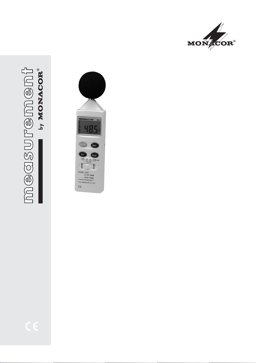
DIGITAL-SCHALLPEGELMESSGERÄT
DIGITAL SOUND LEVEL METER
SM-2
Best.-Nr. 29.1870
Page 2

2
Voordat u inschakelt ...
Wij wensen u veel plezier met uw nieuwe apparaat van MONACOR. Lees deze gebruikershandleiding grondig door, alvorens het apparaat
in gebruik te nemen. Alleen zo leert u alle functies kennen, vermijdt u foutieve bedien ing en
behoedt u zichzelf en het apparaat voor even tuele schade door ondeskundig gebruik. Bewaar
de hand leiding voor latere raadpleging.
De Nederlandse tekst begint op pagina 12.
NL
B
Antes de cualquier instalación ...
Le deseamos una buena utilización para su
nuevo aparato MONACOR. Por favor, lea estas
instrucciones de uso atentamente antes de hacer
funcionar el aparato. De esta manera conocerá
todas las funciones de la unidad, se prevendrán
errores de operación, usted y el aparato estarán
protegidos en contra de todo daño causado por
un uso inadecuado. Por favor, guarde las instrucciones para una futura utilización.
El texto en español empieza en la página 14.
E
Avant toute mise en service ...
Nous vous souhaitons beaucoup de plaisir à utiliser cet appareil MONACOR. Lisez ce mode
dʼemploi entièrement avant toute utilisation.
Uniquement ainsi, vous pourrez apprendre lʼensemble des possibilités de fonctionnement de
lʼappareil, éviter toute manipulation erronée et
vous protéger, ainsi que lʼappareil, de domma ges éventuels engendrés par une utilisation
inadaptée. Conservez la notice pour pouvoir
vous y reporter ultérieurement.
La version française commence à la page 8.
F
B
CH
Prima di accendere ...
Vi auguriamo buon divertimento con il vostro
nuovo apparecchio di MONACOR. Leggete
attentamente le istruzioni prima di mettere in
funzione l'apparecchio. Solo così potete cono scere tutte le funzionalità, evitare comandi
sbagliati e proteggere voi stessi e l'apparecchio
da eventuali danni in seguito ad un uso improprio. Conservate le istruzioni per poterle consultare anche in futuro.
Il testo italiano inizia a pagina 10.
I
Bevor Sie einschalten ...
Wir wünschen Ihnen viel Spaß mit Ihrem neuen
Gerät von MONACOR. Bitte lesen Sie diese
Bedienungsanleitung vor dem Betrieb gründlich
durch. Nur so lernen Sie alle Funktionsmöglichkeiten kennen, ver meiden Fehlbedienungen
und schützen sich und Ihr Gerät vor eventuellen
Schäden durch unsachge mäßen Ge brauch.
Heben Sie die Anleitung für ein späteres Nachlesen auf.
Der deutsche Text beginnt auf der Seite 4.
D
A
CH
Before you switch on ...
We wish you much pleasure with your new
MONACOR unit. Please read these operating
instructions carefully prior to operating the unit.
Thus, you will get to know all functions of the
unit, operating errors will be prevented, and
yourself and the unit will be protected against
any damage caused by improper use. Please
keep the oper ating instructions for later use.
The English text starts on page 6.
GB
Przed Uruchomieniem
...
Życzymy zadowolenia z nowego produktu
MONACOR. Dzięki tej instrukcji obsługi będą
państwo w stanie poznać wszystkie funkcje
tego urządzenia. Stosując się do instrukcji
unikną państwo błędów i ewentualnego uszkodzenia urządzenia na skutek nieprawidłowego
użytkowania. Prosimy zachować instruk cję.
Tekst polski za czyna się na stronie 16.
PL
Page 3
3
1
2
3
4
6
5
7
8
9
10
11
Page 4
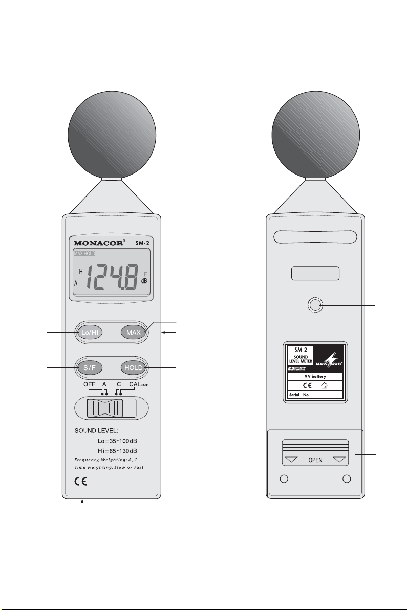
Auf der ausklappbaren Seite 3 finden Sie alle
beschriebenen Bedien elemente und Anschlüsse.
1 Übersicht der Bedienelemente
und Anschlüsse
1 Messmikrofon mit aufgesetztem Windschutz
2 Display
3 Taste Lo/ Hi für die Bereichsumschaltung
unterer Bereich 35 – 100 dB = Grundeinstellung
nach dem Einschalten; links im Display wird „Lo“
(low = niedrig) angezeigt
oberer Bereich 65 – 130 dB; links im Display wird
„Hi“ (high = hoch) angezeigt
4 Taste S/ F zum Umschalten der Messdynamik für
sich schnell ändernde Schallpegel (Grundeinstellung; rechts im Display wird „F“ angezeigt) und für
sich langsam ändernde Schallpegel (Anzeige „S“)
5 Trimmregler zum Kalibrieren der Anzeige auf
94 dB; dazu den Schiebeschalter (9) in die Position
„CAL“ stellen
6 Taste MAX zum Ein- und Ausschalten der Mes-
sung des maximalen Pegels; bei eingeschalteter
Funktion wird oben links im Display „MAX HOLD“
angezeigt
7 3,5-mm-Klinkenbuchse, Ausgang für die verstärkte
Mikrofon spannung und eine pegelproportionale
Gleichspannung (siehe Kapitel 6)
8 Taste HOLD zum Festhalten des momentanen
Messwertes; bei eingeschalteter Funktion wird
oben im Display „DATA HOLD“ angezeigt
9 Schiebeschalter
OFF = Messgerät ausgeschaltet
A = Bewertungsfilter eingeschaltet; die Mes-
sung entspricht der Wahrnehmung des
mensch lichen Ohrs
C = Filter ausgeschaltet; die Messung ent-
spricht dem physikalischen Schall pegel
CAL = Kalibrieren der Anzeige auf 94 dB mit dem
Trimmregler (5)
10 Gewindebuchse mit Fotogewinde (6,3 mm /
1
/4″)
zur Montage des Messgerätes auf ein Stativ
11 Batteriefachdeckel
2 Hinweise für den sicheren Gebrauch
Das Gerät entspricht allen erforder lichen Richt linien
der EU und ist deshalb mit gekennzeichnet.
G
Das Instrument ist nur zur Verwendung im Innenbereich ge eignet. Schützen Sie es vor Tropf- und
Spritzwasser, hoher Luftfeuchtigkeit und Hitze
(zulässiger Einsatztemperaturbereich 0 – 40 °C).
G
Verwenden Sie für die Reinigung nur ein trockenes,
weiches Tuch, auf keinen Fall Chemikalien oder
Wasser.
G
Wird das Gerät zweckentfremdet, falsch angeschlossen, nicht richtig be dient oder nicht fachgerecht repariert, kann keine Garantie für das Ge rät
und keine Haftung für daraus resultierende Sachoder Personenschäden übernommen werden.
3 Verwendungsmöglichkeiten
Das Gerät SM-2 dient zur Schallpegelmessung. Mit
dem Instrument lässt sich z. B. der Frequenzgang
einer Audioanlage, der Wirkungsgrad und die Schallabstrahlung von Lautsprechern oder der Geräusch pegel in Räumen feststellen. Zur Berücksichtigung der
menschlichen Hör eigenschaften kann ein Bewertungsfilter eingeschaltet werden.
4 Inbetriebnahme
1) Mit dem Schiebeschalter (9) das Instrument einschalten (Position „A“, „C“ oder „CAL“).
2) Im Display (2) wird eine Anzeige sichtbar. Wenn
nicht, muss eine 9-V-Batterie eingesetzt werden.
Dazu den Batteriefachdeckel (11) abnehmen. Die
Batteriekontakte auf die Batterie stecken, die Batterie
in das Fach legen und den Deckel wieder schließen.
Er scheint unten links im Display die Anzeige
„BAT“, ist die Batterie verbraucht und muss erneuert werden.
3) Zur Montage des Gerätes auf ein Stativ kann die
Gewindebuchse (10) mit Fotogewinde (6,3 mm/
1
/4″) verwendet werden.
4) Nach dem Betrieb immer das Gerät ausschalten,
sonst wird die Batterie unnötig verbraucht: Den
Schiebeschalter (9) in die Position „OFF“ stellen.
Wird das Instrument längere Zeit nicht ge braucht, sollte die Batterie herausgenommen werden. So werden bei einem Auslaufen der Batterie
mögliche Schäden am Gerät vermieden.
Werfen Sie verbrauchte Batterien oder de fekte Akkus nicht in den Hausmüll, sondern
geben Sie sie nur in den Sondermüll (z. B.
Sammelbehälter bei Ihrem Einzelhändler)
Soll das Gerät endgültig aus dem Betrieb
genommen werden, übergeben Sie es zur
umweltgerechten Entsorgung ei nem örtlichen Recycling betrieb.
D
A
CH
4
Page 5

5 Schallpegel messen
1) Für eine genaue Messung zuvor die Kalibrierung
überprüfen: Den Schiebeschalter (9) in die Position
„CAL“ stellen. Das Display sollte 94,0 dB anzeigen.
Wenn nicht, mithilfe eines Schraubendrehers den
Trimmregler (5) so einstellen, dass 94,0dB angezeigt wird.
2) Soll der Schallpegel entsprechend der Wahrnehmung des menschlichen Ohrs gemessen werden,
den Schiebeschalter in die Position „A“ stellen. In
der Position „C“ wird der physikalische Schallpegel
gemessen (linear).
3) Das Instrument zur Messung waagerecht und mit
dem Mikrofon (1) in Richtung der Schallquelle halten.
4) Nach dem Einschalten ist immer der untere Mess bereich 35 – 100 dB eingestellt. Links im Display
wird „Lo“ (low = niedrig) angezeigt.
Werden über 100 dB gemessen, erscheint
rechts unten im Display die Anzeige „OVER“. Dann
mit der Taste Lo/ Hi (3) in den oberen Bereich
65 – 130 dB schalten. Anstelle „Lo“ erscheint im
Display „Hi“ (high = hoch).
Werden im oberen Bereich weniger als 65 dB
ge-messen, erscheint ebenfalls die Anzeige
„OVER“. Dann mit der Taste Lo/ Hi wieder zurück
auf den unteren Bereich schalten.
5) Nach dem Einschalten ist die Messdynamik auf
sich schnell ändernde Schallpegel eingestellt.
Rechts im Display wird „F“ (fast = schnell) angezeigt. Zum Messen von Schallpegel, die sich langsam ändern, mit der Taste S/ F (4) auf den zweiten
Dynamikbereich umschalten. Die Anzeige wechselt
von „F“ auf „S“ (slow = langsam).
6) Um die Anzeige des momentanen Messwertes
festzuhalten, die Taste HOLD (8) drücken. Oben im
Display erscheint die Anzeige „DATA HOLD“. Zum
Zurückschalten auf den aktuellen Messwert die
Taste HOLD erneut betätigen.
7) Soll der maximal auftretende Pegel festgestellt
werden, die Taste MAX (6) drücken. Oben im Display erscheint die Anzeige „MAX HOLD“. Jetzt wird
der lauteste Pegelwert, der nach dem Drücken der
Taste MAX auftritt, festgehalten. Zum Ausschalten
der Funktion die Taste MAX erneut betätigen.
Hinweise
a Der gemessene Schallpegel ist sehr stark abhän-
gig vom Abstand des Messgerätes zur Schallquelle. Bei der Messung muss ein definierter
Abstand eingehalten werden (z. B. bei Lautsprechermessungen 1 m) oder es muss der Abstand
angegeben werden, bei dem gemessen wurde.
b Der gemessene Pegel ist ebenfalls vom Winkel zur
Schallquelle abhängig. Eventuell ist es notwendig,
bei verschiedenen Winkeln (jedoch bei gleichem
Abstand) die Pegel zu messen und so das Schallabstrahlverhalten der Schallquelle festzustellen.
6 Mikrofonsignal oder pegelproportionale
Gleich spannung abnehmen
An der Ausgangsbuchse (7) liegen folgende Spannungen an, die zu einer pegelabhängigen Steuerung oder
zur weiteren Analyse abgenommen werden können.
Dazu an die Buchse einen 3-poligen 3,5-mm-Klinken stecker an schließen.
Signale am angeschlossenen Klinkenstecker
Spitze – Schaft:
Mikrofonsignal
im unteren Messbereich „Lo“ 38 mV/dB
im oberem Messbereich „Hi“ 8,3 mV/dB
Impedanz 100 Ω
Ring – Schaft:
pegelproportionale Gleichspannung 10 mV/dB
Impedanz 100 Ω
7 Technische Daten
Anzeige:. . . . . . . . . . . . . . 17-mm-LCD, 31/2-stellig
Messbereiche
Lo (low): . . . . . . . . . . . 35 – 100 dB
Hi (high): . . . . . . . . . . . 65 – 130 dB
Auflösung: . . . . . . . . . . 0,1 dB
Genauigkeit: . . . . . . . . . . ±1,5 dB bei 94 dB, 1 kHz
Frequenzbereich:. . . . . . . 31,5 –8000Hz
Pegelbewertung: . . . . . . . A oder C
Mikrofontyp: . . . . . . . . . . . Elektret-Mikrofon
Ausgangsbuchse
(Signale am Klinkenstecker)
Spitze – Schaft: . . . . . . Mikrofonsignal,
Impedanz 100 Ω
Ring – Schaft:. . . . . . . . pegelproportionale
Gleichspannung
10 mV/dB, 100 Ω
Einsatztemperatur: . . . . . 0–40 °C
Stromversorgung: . . . . . . 1 × 9-V-Batterie
Abmessungen:. . . . . . . . . 63 × 253 × 30 mm
Gewicht:. . . . . . . . . . . . . . 250 g
Änderungen vorbehalten.
D
A
CH
5
Diese Bedienungsanleitung ist urheberrechtlich für MONACOR®INTERNATIONAL GmbH & Co. KG ge schützt.
Eine Reproduktion für eigene kommerzielle Zwecke – auch auszugsweise – ist untersagt.
Page 6
GB
6
All operating elements and connections described
can be found on the fold-out page 3.
1 Operating Elements and Connections
1 Measuring microphone with windshield
2 Display
3 Key Lo/ Hi for selecting the range
lower range 35 – 100 dB = basic setting after
switching on; on the left side of the display “Lo”
(low) is indicated
upper range 65 –130dB; on the left side of the dis-
play “Hi” (high) is indicated
4 Key S/ F for selecting the dynamic measuring
mode for sound levels changing fast (basic setting;
on the right side of the display “F” is indicated) and
for sound levels changing slowly (indication “S”)
5 Trimming control for calibrating the indication to
94 dB; for this purpose, set the sliding switch (9) to
the position “CAL”
6 Key MAX for switching on or off the measurement
of the maximum level; with the function switched
on, “MAX HOLD” is indicated at the left top of the
display
7 3.5 mm jack, output for the amplified microphone
volt age and a DC voltage proportional to level (see
chapter 6)
8 Key HOLD for holding the present value measured;
with the function switched on, “DATA HOLD” is
shown at the top of the display
9 Sliding switch
OFF = meter switched off
A = weighting filter switched on; the measure-
ment corresponds to the auditory sensation of the human ear
C = filter switched off; the measurement corre-
sponds to the physical sound level
CAL = calibration of the indication to 94 dB with
the trimming control (5)
10 Threaded jack (6.3 mm/
1
/4″) for mounting the meter
on a stand
11 Battery compartment cover
2 Safety Notes
This unit corresponds to all required directives of the
EU and is therefore marked with .
G
The meter is suitable for indoor use only. Protect it
against dripping water and splash water, high air
humidity, and heat (admissible ambient temperature
range 0 – 40 °C).
G
For cleaning only use a dry, soft cloth; never use
chemicals or water.
G
No guarantee claims for the unit and no liability for
any resulting personal damage or material damage
will be accepted if the unit is used for other purposes
than originally intended, if it is not correctly con nected, operated or not repaired in an expert way.
3 Applications
The SM-2 serves for sound level measurement. The
meter allows to determine e. g. the frequency response
of an audio system, the efficiency and the sound radiation of speakers, or the noise level in rooms. For taking
into account the auditory sensation of the human ear, a
weighting filter can be switched on.
4 Operation
1) Switch on the meter with the sliding switch (9) [position “A”, “C”, or “CAL”].
2) An indication is displayed (2). If not, insert a 9 V battery. For this purpose, remove the battery compartment cover (11). Connect the battery contacts to
the battery, insert the battery in the compartment,
then close the cover.
If “BAT” is displayed at the left bottom, the bat-
tery is exhausted and must be replaced.
3) For mounting the unit on a stand, the threaded jack
(6.3 mm/
1
/4″) [10] can be used.
4) Always switch off the unit after operation, otherwise
the battery will be consumed unnecessarily: Set the
sliding switch (9) to the position “OFF”.
If the meter is not used for a longer period, the
battery should be removed to prevent damage to
the unit in case of battery leakage.
Never throw dead batteries or defective
recharge able batteries into the household
rubbish; always take them to a special waste
disposal (e. g. collect ing container at your
retailer).
If the unit is to be put out of operation de finitively, take it to a local recycling plant for a
disposal which is not harmful to the environment.
Page 7

5 Measuring the Sound Level
1) For a precise measurement, check the calibration
beforehand: Set the sliding switch (9) to the position “CAL”. 94.0 dB should be displayed. If not,
adjust the trimming control (5) by means of a
screw driver so that 94.0 dB is displayed.
2) For measuring the sound level in accordance with
the auditory sensation of the human ear, set the
sliding switch to the position “A”. In the position “C”,
the physical sound level is measured (linear).
3) For measuring, hold the meter horizontally with the
microphone (1) pointing to the sound source.
4) After switching on, the lower measuring range
35 – 100 dB is always selected. On the left side of
the display “Lo” is indicated.
When measuring values exceeding 100 dB,
“OVER” is indicated at the right bottom of the display. In this case, switch to the upper range
65 – 130 dB with the key Lo/Hi (3). Instead of “Lo”,
“Hi” is displayed.
When measuring values below 65 dB in the
upper range, “OVER” is also indicated. In this case,
return to the lower range with the key Lo/ Hi.
5) After switching on, the dynamic measuring mode is
set to sound levels changing fast. On the right side
of the display, “F” (fast) is indicated. For measuring
sound levels changing slowly, switch to the second
mode with the key S/ F (4). The indication changes
from “F” to “S” (slow).
6) For holding the present value measured, press the
key HOLD (8). At the top of the display “DATA
HOLD” is indicated. To return to the present value
measured, actuate the key HOLD once again.
7) To determine the maximum level occurring, press
the key MAX (6). At the top of the display “MAX
HOLD” is indicated. Now the level value of the
highest volume occurring after actuating the key
MAX will be held. For switching off the function,
actuate the key MAX once again.
Notes
a The sound level measured largely depends on the
distance of the meter from the sound source. When
measuring, observe a defined distance (e. g. 1 m
for speaker measurements) or state the distance at
which the measurement was made.
b The level measured also depends on the angle to
the sound source. It may be necessary to measure
the levels at different angles (but at the same distance) to determine the sound radiation be haviour
of the sound source.
6 Picking up a Microphone Signal or a
DC Voltage proportional to Level
At the output jack (7), the following voltages are pres ent to be picked up for a control depending on the level
or for further analysis. For this purpose, connect a
3-pole 3.5 mm plug to the jack.
Signals at the 3.5 mm plug connected
tip – body:
microphone signal
in the lower measuring range “Lo” 38 mV/dB
in the upper measuring range “Hi” 8.3 mV/dB
impedance 100 Ω
ring – body:
DC voltage proportional to level 10 mV/dB
impedance 100 Ω
7 Specifications
Display: . . . . . . . . . . . . . . 17 mm LCD, 31/2 digits
Measuring ranges
Lo (low): . . . . . . . . . . . 35 – 100 dB
Hi (high): . . . . . . . . . . . 65 – 130 dB
Resolution:. . . . . . . . . . 0.1 dB
Accuracy:. . . . . . . . . . . . . ±1.5 dB at 94dB, 1kHz
Frequency range: . . . . . . 31.5 – 8000 Hz
Level weighting:. . . . . . . . A or C
Type of microphone: . . . . electret microphone
Output jack
(signals at the plug)
tip – body:. . . . . . . . . . . microphone signal,
impedance 100 Ω
ring – body:. . . . . . . . . . DC voltage proportional to
level 10 mV/dB, 100Ω
Ambient temperature: . . . 0 –40°C
Power supply: . . . . . . . . . 1 × 9 V battery
Dimensions:. . . . . . . . . . . 63 × 253 × 30 mm
Weight:. . . . . . . . . . . . . . . 250 g
Subject to technical modification.
GB
7
All rights reserved by MONACOR®INTERNATIONAL GmbH & Co. KG. No part of this instruction manual may
be reproduced in any form or by any means for any commercial use.
Page 8
Vous trouverez sur la page 3, dépliable, les éléments et branchements décrits.
1 Eléments et branchements
1 Microphone de mesure avec bonnette de protec-
tion
2 Affichage
3 Touche Lo/ Hi pour la commutation de plages :
plage inférieure 35 – 100 dB = réglage de base
après la mise sous tension : à gauche sur lʼaf fichage “Lo” (low = faible) est affiché
plage supérieure 65 – 130 dB : à gauche sur lʼaf -
fichage “Hi” (high = élevé) est affiché
4 Touche S/ F pour commuter la dynamique de me -
sure pour des niveaux sonores se modifiant
vite (réglage de base : à droite sur lʼaffichage, “F”
est affiché) et pour des niveaux sonores se modi fiant lentement (affichage “S”)
5 Potentiomètre trimmer pour calibrer lʼaffichage sur
94 dB : mettez le potentiomètre (9) sur la position
“CAL”.
6 Touche MAX pour activer/ désactiver la mesure du
niveau maximal : si la fonction est activée, en haut
à gauche sur lʼaffichage “MAX HOLD” sʼaffiche.
7 Prise jack 3,5, sortie pour la tension micro ampli-
fiée et une tension DC proportionnelle au niveau
(voir chapitre 6).
8 Touche HOLD pour geler la valeur de mesure
momentanée : si la fonction est activée, en haut
sur lʼaffichage apparaît “DATA HOLD”.
9 Potentiomètre à glissières
OFF = sonomètre déconnecté
A = filtre de pondération allumé : la mesure
correspond à la perception de lʼoreille
humaine
C = filtre éteint : la mesure correspond au
niveau sonore physique
CAL = calibrage de lʼaffichage sur 94 dB avec le
potentiomètre trimmer (5).
10 Prise filetée avec filetage (6,3 mm/
1
/4″) pour mon-
ter le sonomètre sur un pied
11 Couvercle compartiment batterie
2 Conseils dʼutilisation et de sécurité
Cet appareil répond à toutes les directives nécessaires
de lʼUnion Européenne et porte donc le symbole .
G
Lʼappareil nʼest conçu que pour une utilisation en
intérieur. Protégez-le de tout type de projections
dʼeau, des éclaboussures, dʼune humidité élevée et
de la chaleur (plage de température de fonctionnement autorisée : 0 – 40 °C).
G
Pour le nettoyer, utilisez un chiffon sec et doux, en
aucun cas de produits chimiques ou dʼeau.
G
Nous déclinons toute responsabilité en cas de dommages corporels ou matériels si lʼappareil est utilisé
dans un but autre que celui pour lequel il a été
conçu, sʼil nʼest pas correctement branché, utilisé ou
sʼil nʼest pas réparé par un technicien habilité ; en
outre, la garantie deviendrait caduque.
3 Possibilités dʼutilisation
Le SM-2 permet dʼeffectuer des mesures de niveau
sonore. Vous pouvez ainsi mesurer la courbe de
réponse dʼune installation audio, le rendement et la
dispersion sonore de haut-parleurs ou constater le
niveau sonore dʼune pièce. Un filtre de pondération
peut être activé pour tenir compte de la perception de
lʼoreille humaine.
4 Fonctionnement
1) Avec le potentiomètre (9), allumez lʼappareil (position “A”, “C” ou “CAL”).
2) Sur lʼaffichage (2), une indication est visible. Si ce
nʼest pas le cas, vous devez insérer une batterie
9 V ; retirez le couvercle (11) du compartiment batterie. Placez les contacts de batterie sur la batterie,
glissez la batterie dans le compartiment puis refermez le couvercle.
Si en bas à gauche sur lʼaffichage apparaît
“BAT”, la batterie est morte et doit être remplacée.
3) Pour monter lʼappareil sur un pied, la prise filetée
(10) avec filetage 6,3 mm/
1
/4″ peut être utilisée.
4) Après le fonctionnement, éteignez toujours lʼap pareil sinon la batterie est inutilement utilisée ; mettez le potentiomètre (9) sur “OFF”.
En cas de non-utilisation prolongée, il convient
de retirer la batterie car elle pourrait couler et
endommager lʼappareil.
Ne jetez pas les batteries ou accumulateurs
usagés ou défectueux dans la poubelle
domes tique, déposez-les dans une poubelle
spéciale ou ramenez-les à votre revendeur.
Lorsque lʼappareil est définitivement retiré du
circuit de distribution, vous devez le déposer
dans une usine de recyclage adaptée pour
contribuer à son élimination non polluante.
F
B
CH
8
Page 9

5 Mesures de niveau sonore
1) Pour une mesure précise, vérifiez auparavant le
calibrage : mettez le potentiomètre (9) sur la position “CAL” ; lʼaffichage doit indiquer 94,0 dB. Si ce
nʼest pas le cas, à lʼaide dʼun petit tournevis, réglez
le potentiomètre trimmer (5) de telle sorte que
94,0 dB sʼaffiche.
2) Si le niveau sonore doit être mesuré selon la perception de lʼoreille humaine, mettez le poten tiomètre sur la position “A”. Sur la position “C”, le
niveau sonore physique (linéaire) est mesuré.
3) Tenez lʼinstrument pour effectuer la mesure à lʼhorizontale, le micro (1) en direction de la source
sonore.
4) Après lʼallumage, la plage inférieure 35 – 100 dB
est toujours réglée ; à gauche, sur lʼaffichage, “Lo”
(low = faible) est affiché.
Pour des mesures au-delà de 100 dB, “OVER”
sʼaffiche en bas à droite ; avec la touche Lo/ Hi (3)
commutez dans la plage supérieure 65 – 130 dB ;
“Hi” (high = élevé) sʼaffiche à la place de “Lo”.
Si dans la plage supérieure, la mesure est in férieure à 65 dB, “OVER” apparaît également. Avec
la touche Lo/ Hi, revenez dans la plage in férieure.
5) Après lʼallumage, la dynamique de mesure est
réglée sur des niveaux se modifiant rapidement.
Sur lʼaffichage, à droite, “F” (fast = rapide) sʼaf fiche ; pour mesurer des niveaux se modifiant plus
lentement, commutez avec la touche S/ F (4) sur la
seconde plage de dynamique : lʼaffichage passe
alors de “F” sur “S” (slow = lentement).
6) Pour conserver lʼaffichage de la valeur de mesure
momentanée, enfoncez la touche HOLD (8). En
haut sur lʼaffichage, “DATA HOLD” est visible. Pour
revenir à la valeur de mesure actuelle, enfoncez
une nouvelle fois la touche HOLD.
7) Si le niveau maximal doit être constaté, enfoncez la
touche MAX (6). En haut sur lʼaffichage, “MAX
HOLD” est visible. Maintenant la valeur de niveau
le plus fort qui apparaît après la pression sur la
touche MAX est gelée. Pour désactiver la fonction,
enfoncez la touche MAX une nouvelle fois.
Conseils
a Le niveau sonore mesuré dépend grandement de
la distance entre lʼappareil et la source. Lors de la
mesure, une distance définie doit être conservée
(par exemple pour des mesures de haut-parleurs :
1 m) ou la distance à laquelle la mesure a été effectuée doit être indiquée.
b Le niveau sonore dépend également de lʼangle de
positionnement par rapport à la source. Il peut être
nécessaire de mesurer les niveaux sous plusieurs
angles (à la même distance) et dʼétudier le comportement de dispersion sonore de la source.
6 Prélever le signal micro ou la tension
DC proportionnelle au niveau
Les tensions suivantes se trouvent à la prise de sortie
(7) : elles peuvent être prises pour une commande,
fonction du niveau, ou une étude ultérieure. Reliez une
fiche jack 3,5 mâle 3 pôles à cette prise.
Signaux à la fiche jack reliée
pointe – corps
signal micro
dans la plage de mesure inférieure “Lo” 38 mV/dB
dans la plage de mesure supérieure “Hi” 8,3 mV/dB
impédance 100 Ω
bague – corps
tension DC proportionnelle au niveau 10 mV/dB
impédance 100 Ω
7 Caractéristiques techniques
Affichage : . . . . . . . . . . . . LCD 17 mm, 31/2 positions
Plages de mesure
Lo (low) : . . . . . . . . . . . 35 – 100 dB
Hi (high) : . . . . . . . . . . 65 –130 dB
Résolution : . . . . . . . . . 0,1 dB
Précision : . . . . . . . . . . . . ±1,5 dB à 94 dB, 1 kHz
Bande passante :. . . . . . . 31,5 –8000Hz
Pondération niveaux : . . . A ou C
Type micro :. . . . . . . . . . . micro électret
Prise de sortie
(signaux à la fiche mâle)
pointe – corps : . . . . . . signal micro,
impédance 100 Ω
bague – corps : . . . . . . tension DC proportion nel le
au niveau
10 mV/dB, 100Ω
Température fonc. : . . . . . 0 –40°C
Alimentation :. . . . . . . . . . 1 × batterie 9 V
Dimensions : . . . . . . . . . . 63 × 253 × 30 mm
Poids : . . . . . . . . . . . . . . . 250 g
Tout droit de modification réservé.
F
B
CH
9
Notice dʼutilisation protégée par le copyright de MONACOR®INTERNATIONAL GmbH & Co. KG. Toute reproduction même partielle à des fins commerciales est interdite.
Page 10
A pagina 3, se aperta completamente, vedrete
sempre gli elementi di comando e i collegamenti
descritti.
1 Elementi di comando e collegamenti
1 Microfono di misura con protezione antivento
2 Display
3 Tasto Lo/ Hi per selezione campo
zona inferiore 35 – 100 dB = impostazione base
dopo lʼaccensione; sul display, a sinistra, si vede
“Lo” (low = basso)
zona superiore 65 – 130 dB; sul display, a sinistra,
si vede “Hi” (high = alto)
4 Tasto S/ F per cambiare la dinamica di misurazione
per livelli sonori soggetti a rapidi cambiamenti
(impostazione base; a destra, sul display si vede
“F”) e per livelli sonori soggetti a lenti cambiamenti
(indicazione “S”)
5 Potenziometro per tarare lʼindicazione su 94 dB;
per fare questo spostare il cursore (9) in posizione
“CAL”
6 Tasto MAX per attivare e disattivare la misurazione
del livello massimo; se la funzione è stata attivata,
in alto a sinistra del display si legge “MAX HOLD”
7 Presa dʼuscita jack 3,5 mm per la tensione amplifi-
cata del microfono e per la tensione continua proporzionale al livello (vedi cap. 6)
8 Tasto HOLD per bloccare il valore misurato
momentaneo; se la funzione è stata attivata, in alto
sul display si legge “DATA HOLD”
9 Cursore
OFF = misuratore spento
A = filtro di valutazione attivato; la misura corri-
sponde allʼudito umano
C = filtro disattivato: la misura corrispondo al
livello sonoro fisico
CAL = taratura dellʼindicazione a 94 dB con il
potenziometro (5)
10 Presa con filettatura tipo macchina fotografica
(6,3 mm/
1
/4″) per montare il misuratore su uno sta-
tivo
11 Coperchio del vano batteria
2 Avvertenze di sicurezza
Questʼapparecchio è conforme a tutte le direttive
richieste dellʼUE e pertanto porta la sigla .
G
Lo strumento è previsto solo per lʼuso allʼinterno di
locali. Proteggerlo dallʼacqua gocciolante e dagli
spruz zi dʼacqua, da alta umidità dellʼaria e dal calore
(temperatura dʼimpiego ammessa fra 0 °C e 40 °C).
G
Per la pulizia usare solo un panno morbido, asciutto;
non impiegare in nessun caso prodotti chimici o
acqua.
G
Nel caso di uso improprio, di collegamenti sbagliati,
di impiego scorretto o di riparazione non a regola
dʼarte del misuratore, non si assume nessuna re sponsabilità per eventuali danni consequenziali a
persone o a cose e non si assume nessuna garanzia per lo strumento.
3 Possibilità dʼimpiego
Lo strumento SM-2 serve per misurare il livello sonoro.
Si possono misurare la riposta in frequenza di un im pianto audio, lʼefficienza e le caratteristiche di diffusione sonora di altoparlanti o il livello sonoro in am bienti. Per tener conto delle caratteristiche dellʼudito
umano si può inserire un filtro di valutazione.
4 Messa in funzione
1) Accendere lo strumento con il cursore (9) [posizione “A”, “C” o “CAL”].
2) Sul display (2) si vedono dei simboli. Altrimenti
occorre inserire una batteria di 9 V. Per fare ciò
togliere il coperchio (11) del vano batteria. Inserire i
contatti sulla batteria, mettere la batteria nel vano e
richiudere il coperchio.
Se in basso a sinistra sul display se legge “BAT”,
vuol dire che la batteria è scarica e che occorre
sostituirla.
3) Se si desidera montare lo strumento su uno stativo,
si può usare la presa (10) con filettatura tipo macchina fotografica (6,3 mm/
1
/4″).
4) Dopo lʼuso spegnere lo strumento per non consumare le batterie: spostare il cursore (9) in posizione
“OFF”.
Se lo strumento non viene usato per un periodo
prolungato conviene togliere le batterie. Così si evitano danni nel caso le batterie dovessero perdere.
Non gettare le batterie scariche o difettose
nelle immondizie di casa bensì negli appositi
contenitori (p. es. presso il vostro rivenditore).
Se si desidera eliminare lʼapparecchio definitivamente, consegnarlo per lo smal timento
ad unʼistituzione locale per il riciclaggio.
I
10
Page 11

5 Misura del livello sonoro
1) Per una misurazione esatta occorre dapprima controllare la taratura: spostare il cursore (9) in posizione “CAL”. Il display dovrebbe indicare 94 dB. Al tri menti regolare il potenziometro (5) con lʼaiuto di
un cacciavite in modo che lʼindicazione sia di 94 dB.
2) Se si desidera misurare il livello sonoro secondo la
percezione dellʼudito umano, portare il cursore
nella posizione “A”. Nella posizione “C” infatti si
misura il livello sonoro fisico (lineare).
3) Per la misurazione tenere lo strumento in posizione
orizzontale e con il microfono (1) in direzione della
fonte sonora.
4) Dopo lʼaccensione è impostato sempre il campo
inferiore di misura 35 –100dB. A sinistra del display
si vede “Lo” (low = basso).
Se si misurano più di 100 dB, sul display, in
basso a destra, appare “OVER”. In questo caso
passare nel campo superiore 65 – 130 dB azionan do il tasto Lo/ Hi (3). Al posto di “Lo” si vede ora “Hi”
(high = alto).
Se nel campo superiore si misurano meno di
65 dB, sul display appare pure “OVER”. Quindi con
il tasto Lo/ Hi ritornare nel campo inferiore.
5) Dopo lʼaccensione, lo strumento è impostato su
livelli sonori soggetti a rapidi cambiamenti. Sul
display, a destra, si vede “F” (fast = veloce). Per
misu rare i livelli sonori che cambiano lentamente,
con il tasto S/ F (4) si può selezionare il secondo
campo dinamico. Lʼindicazione passa da “F” a “S”
(slow = lento).
6) Se si vuole bloccare la visualizzazione del livello
momentaneo, premere il tasto HOLD (8). Sul
display, in alto, si legge “DATA HOLD”. Per ritornare
alla misura del livello attuale premere di nuovo il
tasto HOLD.
7) Per trovare il livello massimo manifestatosi, premere il tasto MAX (6). Sul display, in alto, si legge
“MAX HOLD”. Ora viene bloccato il valore massimo
che si presenta dopo la pressione del tasto MAX.
Per disattivare la funzione premere di nuovo il tasto
MAX.
Alcuni consigli
a Il livello sonoro misurato dipende molto dalla
distanza dello strumento dalla fonte. Nella misura
occorre attenersi ad una distanza definita (p. es.
1 m per gli altoparlanti), oppure si deve indicare la
distanza di rilevamento.
b Il livello dipende anche dallʼangolo di rilevamento
dalla fonte. Eventualmente occorre misurare i livelli
con angoli diversi (a distanza costante), per individuare lo stato di diffusione sonora della sorgente.
6 Prelevare il segnale del microfono o
la ten sione continua proporzionale al
livello
Alla presa dʼuscita (7) sono presenti le seguenti tensioni che possono essere prelevate per il pilotaggio di
apparecchi secondo il livello sonoro, oppure per ulte riori analisi. In questo caso inserire nella presa un jack
3,5 mm a 3 poli.
Segnali sul jack collegato:
punta – gambo:
segnale del microfono
nel campo inferiore “Lo” 38 mV/dB
nel campo superiore “Hi” 8,3 mV/dB
impedenza 100 Ω
anello – gambo:
tensione continua proporzionale al livello sonoro
10 mV/dB
impedenza 100 Ω.
7 Dati tecnici
Display: . . . . . . . . . . . . . . LCD a 17 mm, 31/2 cifre
Campi di misura
Lo low): . . . . . . . . . . . . 35 –100dB
Hi (high) . . . . . . . . . . . 65 –130dB
Risoluzione . . . . . . . . . 0,1 dB
Precisione:. . . . . . . . . . . . ±1,5 dB a 94dB, 1kHz
Banda di frequenza: . . . . 31,5 – 8000 dB
Valutazione livello:. . . . . . A opp. C
Tipo di microfono: . . . . . . a elettrete
Presa dʼuscita
(segnali sul jack)
punta – gambo: . . . . . . segnale microfono,
impedenza 100 Ω
anello – gambo:. . . . . . tensione continua propor-
zionale al livello,
10 mV/dB, 100Ω
Temperatura dʼimpiego: . . 0 – 40 °C
Alimentazione: . . . . . . . . . batteria 9 V
Dimensioni: . . . . . . . . . . . 63 × 253 × 30 mm
Peso: . . . . . . . . . . . . . . . . 250 g
Con riserva di modifiche tecniche.
I
11
La MONACOR®INTERNATIONALGmbH & Co. KG si riserva ogni diritto di elaborazione in qualsiasi forma delle
presenti istruzioni per lʼuso. La riproduzione – anche parziale – per propri scopi commerciali è vietata.
Page 12
Op de uitklapbare pagina 3 vindt u een overzicht
van de bedieningselementen en de aansluitingen.
1 Overzicht van de bedienings-
elementen en aansluitingen
1 Meetmicrofoon met gemonteerd windscherm
2 Display
3 Toets Lo/ Hi voor de bereikselectie
onderste bereik 35 – 100 dB = basisinstelling na
het inschakelen; links op het display verschijnt
“Lo” (low = laag)
bovenste bereik 65 – 130 dB; links op het display
verschijnt “Hi” (high = hoog)
4 Toets S/ F om de meetdynamiek in te stellen voor
snel veranderende geluidsniveaus (basisinstelling;
rechts op het display verschijnt “F”) en voor langzaam veranderende geluidsniveaus (weergave “S”)
5 Trimregelaar om de weergave op 94dB te kalibre-
ren; plaats de schuifschakelaar (9) hiervoor in de
stand “CAL”
6 Toets MAX om de metingen van het maximale
niveau in en uit te schakelen; bij ingeschakelde
functie verschijnt de melding “MAX HOLD” bovenaan links op het display
7 3,5 mm-stekkerbus, uitgang voor de versterkte
microfoonspanning en een gelijkspanning in verhouding tot het niveau (zie hoofdstuk 6)
8 Toets HOLD om de momentele meetwaarde vast
te houden; bij ingeschakelde functie verschijnt de
melding “DATA HOLD” bovenaan op het display
9 Schuifschakelaar
OFF = het meettoestel is uitgeschakeld
A = waarderingsfilter ingeschakeld; de meting
komt overeen met de waarneming door het
menselijke oor
C = filter uitgeschakeld; de meting komt over-
een met het fysische geluidsniveau
CAL = de weergave op 94 dB kalibreren met de
trimregelaar (5)
10 Schroefdraadmof (6,3 mm/
1
/4″) voor montage van
het meettoestel op een statief
11 Deksel van het batterijvakje
2 Veiligheidsvoorschriften
Het apparaat is in overeenstemming met alle vereiste
EU-Richtlijnen en is daarom gekenmerkt met .
G
Het toestel is enkel geschikt voor gebruik binnenshuis. Vermijd druip- en spatwater, uitzonderlijk warme
plaatsen en plaatsen met een hoge vochtigheid
(toegestaan omgevingstemperatuurbereik: 0 –40 °C).
G
Gebruik voor de reiniging uitsluitend een droge,
zachte doek. Gebruik in geen geval chemicaliën of
water.
G
In geval van ongeoorloofd of verkeerd gebruik, foutieve aansluiting, incorrecte bediening of van herstelling door een niet-gekwalificeerd persoon vervalt
de garantie en de verantwoordelijkheid voor hieruit
resulterende materiële of lichamelijke schade.
3 Toepassingen
Het toestel SM-2 dient voor de meting van het geluidsniveau. Met het toestel kunt u b. v. de frequentie van
een audio-installatie, het rendement en de geluiduit straling van luidsprekers of het geluidsniveau in ruimten registreren. Om rekening te houden met de menselijke gehooreigenschappen kunt u een waarderingsfilter inschakelen.
4 Ingebruikname
1) Schakel het instrument in met de schuifschakelaar
(9) [stand “A”, “C” of “CAL”].
2) Op het display (2) wordt een melding weergegeven. Indien dit niet het geval is, brengt u een 9 Vbatterij aan. Neem hiervoor het deksel van het batterijvakje (11) af. Verbind de batterijcontacten met
de batterij, plaats de batterij in het batterijvakje en
sluit het deksel.
Wanneer links onderaan op het display de meld ing “BAT” verschijnt, dan is de batterij leeg en moet
hij worden vervangen.
3) Voor de montage van het apparaat op een statief
kunt u de mof (10) met schroefdraad (6,3 mm/
1
/4″)
gebruiken.
4) Schakel het toestel na gebruik steeds uit, om on nodig verbruik van de batterij te vermijden: Plaats de
keuzeschakelaar (9) in de stand “OFF”.
Indien het toestel voor een langere periode niet
gebruikt wordt, dient u de batterijen eruit te nemen.
Zo blijft het toestel onbeschadigd bij eventueel uitlopen van de batterij.
Geef lege batterijen of defecte accuʼs niet met
het gewone huisvuil mee, maar ver wijder het
als KGA (bijvoorbeeld de inzamelbox in de
gespecialiseerde elektrozaak).
Wanneer het apparaat definitief uit bedrijf
wordt genomen, bezorg het dan voor milieuvriendelijke verwerking aan een plaatselijk
recyclagebedrijf.
NL
B
12
Page 13

5 Het geluidsniveau meten
1) Voor een precieze meting controleert u eerst de
kalibrering: Plaats de keuzeschakelaar (9) in de
stand “CAL”. Op het display zou de waarde 94,0 dB
moeten verschijnen. Indien dit niet het geval is, stelt
u de trimregelaar (5) met een schroevendraaier zo
in, dat 94,0 dB wordt weergegeven.
2) Wenst u het geluidsniveau te meten zoals dit door
het menselijke oor wordt waargenomen, plaats de
schuifschakelaar dan in de stand “A”. In de stand “C”
wordt het fysische geluidsniveau gemeten (lineair).
3) Houd het instrument voor de meting loodrecht en
richt de microfoon (1) naar de geluidsbron.
4) Bij inschakelen is steeds het onderste meetbereik
35 – 100 dB ingesteld. Links op het display verschijnt “Lo” (low = laag).
Indien meer dan 100 dB wordt gemeten, verschijnt de melding “OVER” rechts onder op het display. Schakel dan met de toets Lo/Hi (3) naar het
bovenste bereik 65 –130dB. In plaats van “Lo” verschijnt “Hi” (high = hoog) op het display.
Indien in het bovenste bereik minder dan 65 dB
wordt gemeten, verschijnt eveneens de melding
“OVER”. Schakel dan met de toets Lo/ Hi terug
naar het onderste bereik.
5) Bij inschakelen is de meetdynamiek ingesteld op
snel veranderende geluidsniveaus. Rechts op het
display verschijnt “F” (fast = snel). Om langzaam
veranderende geluidsniveaus te meten, schakelt u
met de toets S/ F (4) naar het tweede dynamische
bereik. De weergave verandert van “F” in “S” (slow
= langzaam).
6) Om de weergegeven meetwaarde vast te houden,
drukt u op de toets HOLD (8). Boven in het display
verschijnt de melding “DATA HOLD”. Om terug te
schakelen naar de huidige meetwaarde, drukt u
nogmaals op de toets HOLD.
7) Wenst u het maximale niveau vast te leggen, dan
drukt u op de toets MAX (6). Boven in het display
verschijnt de melding “MAX HOLD”. Nu wordt de
luidste niveauwaarde vastgehouden die na het
drukken op de toets MAX wordt geregistreerd. Om
de functie uit te schakelen, drukt u opnieuw op de
toets MAX.
Tips
a Het gemeten geluidsniveau is in grote mate afhan-
kelijk van de afstand van het instrument tot de
geluidsbron. Bij de meting moet u een bepaalde
afstand aanhouden (b. v. 1 m bij luidsprekermetingen), ofwel moet de afstand zijn aangegeven waarbij de meting werd uitgevoerd.
b Het gemeten niveau is eveneens afhankelijk van de
hoek met de geluidsbron. Het kan nodig zijn om bij
verschillende hoekstanden (echter bij gelijke af stand) de niveaus te meten en zo de geluiduitstralingsverhouding van de geluidsbron te bepalen.
6 Het microfoonsignaal of de gelijkspan-
ning in verhouding tot het niveau registreren
Op de uitgangsjack (7) kunnen de volgende spanningen voor een niveau-afhankelijke besturing of voor
verdere analyse afgenomen worden. Sluit hiervoor
een 3-polige 3,5 mm-stekker aan op de jack.
signalen op de aangesloten stekker
top – schacht:
microfoonsignaal
in het onderste meetbereik “Lo” 38 mV/dB
in het bovenste meetbereik “Hi” 8,3 mV/dB
Impedantie 100 Ω
ring – schacht:
gelijkspanning 10 mV/dB in verhouding tot niveau
Impedantie 100 Ω
7 Technische gegevens
Weergave: . . . . . . . . . . . . 17-mm-LCD,
3
1
/2 karakters
Meetbereiken
Lo (low): . . . . . . . . . . . 35 – 100 dB
Hi (high): . . . . . . . . . . . 65 – 130 dB
Resolutie:. . . . . . . . . . . 0,1 dB
Precisie:. . . . . . . . . . . . . . ±1,5 dB bij 94dB, 1kHz
Frequentiebereik:. . . . . . . 31,5 –8000Hz
Niveauwaardering:. . . . . . A of C
Microfoontype: . . . . . . . . . Elektretmicrofoon
Uitgangsjack
(signalen op de stekker)
top – schacht: . . . . . . . microfoonsignaal,
impedantie 100 Ω
ring – schacht: . . . . . . . gelijkspanning 10 mV/dB,
100 Ω in verhouding tot
niveau
Omgevings-
temperatuurbereik: . . . . . 0 – 40 °C
Voedingsspanning: . . . . . 1 × 9 V-batterij
Afmetingen: . . . . . . . . . . . 63 × 253 × 30 mm
Gewicht:. . . . . . . . . . . . . . 250 g
Wijzigingen voorbehouden.
NL
B
13
Deze gebruiksaanwijzing is auteursrechterlijk beschermd voor MONACOR®INTERNATIONAL GmbH &
Co. KG. Reproductie voor eigen commerciële doeleinden – ook bij wijze van uitzondering – is niet toegestaan.
Page 14
Puede encontrar todos los elementos de funcionamiento y las conexiones que se describen en la
página 3 desplegable.
1 Elementos y conexiones
1 Micro de medida con protección anti-viento
2 Visualización
3 Tecla Lo/ Hi para la conmutación de zonas:
zona inferior 35 – 100 dB = reglaje de base des-
pués de la puesta en marcha: a la izquierda de
la pantalla aparece el mensaje “Lo” (low = bajo)
zona superior 65 –130dB; a la izquierda de la pan-
talla, aparece el mensaje “Hi” (high = elevado)
4 Tecla S/ F para conmutar la dinámica de medida
para los niveles sonoros que se modifican rápidamente (reglaje de base; a la derecha de la pantalla
aparece el mensaje “F”) y para los niveles sonoros
que se modifican lentamente (aparece el mensaje
“S”)
5 Potenciómetro trimmer para calibrar la pantalla en
94 dB; ponga el potenciómetro (9) en la posición
“CAL”.
6 Tecla MAX para activar/ desactivar la medida del
nivel máximo; si la función está activada, arriba a
la izquierda de la pantalla aparece el mensaje
“MAX HOLD”.
7 Toma jack 3,5, salida para la tensión micro amplifi-
cada y una tensión DC proporcional al nivel (vea
capítulo 6)
8 Tecla HOLD para congelar el valor de medida
momentáneo; si la función está activada, arriba de
la pantalla aparece el mensaje “DATA HOLD”.
9 Potenciómetro deslizante
OFF = sonómetro desconectado
A = filtro de ponderación conectado; la medida
corresponde a la percepción de la oreja
humana
C = filtro desconectado; la medida corres-
ponde al nivel sonoro físico
CAL = calibración de la pantalla en 94dB con el
potenciómetro trimmer (5)
10 Toma con rosca (6,3 mm/
1
/4″) para montar el sonó-
metro sobre pie
11 Tapa compartimiento batería
2 Consejos de utilización y de seguridad
Esta unidad cumple con todas las Directivas requeridas por la CEE y por ello está marcada con el
símbolo .
G
El aparato está fabricado solo para una utilización
en interior. Protéjala de las proyecciones de agua y
salpicaduras, alta humedad del aire, y calor (temperatura de ambiente admisible 0 – 40 °C).
G
Para limpiarlo, utilice un trapo seco y suave, en ningún caso productos químicos o agua.
G
Rechazamos toda responsabilidad en caso de
daños corporales o materiales si el aparato se utiliza
en otro fin para el cual ha sido fabricado, si no está
correctamente conectado, utilizado o reparado por
un técnico especializado; además, por todos estos
mismo motivos el aparato carecería de todo tipo de
garantía
3 Posibilidades de utilización
El SM-2 permite efectuar medidas del nivel sonoro.
Puede así constatar por ejemplo la respuesta de frecuencia de una instalación audio, la eficiencia, la
radiación sonora de los altavoces o el nivel sonoro de
un local. Puede activar un filtro de ponderación para
tener en cuenta propiedades audio humanas.
4 Funcionamiento
1) Con el potenciómetro (9), conecte el aparato (posición “A”, “C”o “CAL”).
2) En la pantalla (2), aparece una indicación visible. Si
no es el caso, debe insertar una batería de 9 V;
saque la tapa (11) del compartimiento batería.
Coloque los contactos de las baterías sobre la
batería, inserte la batería y cierre la tapa.
Si debajo a la izquierda de la pantalla aparece el
mensaje “BAT”, la batería está usada y debe cambiarla.
3) Para montar el aparato sobre pie, utilice la toma
(10) con rosca de 6,3 mm/
1
/4″.
4) Después del funcionamiento, desconecte siempre
el aparato si no la batería se utiliza inútilmente:
ponga el potenciómetro (9) en la posición “OFF”.
En caso de no utilizar el aparato durante un pe riodo prolongado, conviene sacar la batería porque
podrían derramarse y dañar el aparato.
No tire nunca las baterías usadas o defectuosa en una basura doméstica, tírelas en un
container destinado a baterías o devuélvelas
al detallista.
Cuando el aparato está definitivamente
sacado del servicio, debe depositarlo en una
fábrica de reciclaje para contribuir a una eliminación no contaminante.
E
14
Page 15

5 Medidas del nivel sonoro
1) Para una medida precisa, antes de todo verifique la
calibración: ponga el potenciómetro (9) en la posición “CAL”; la pantalla debería indicar 94,0 dB. Si
no es el caso, regule el potenciómetro trimmer (5)
con un destornillador de manera que aparezca en
pantalla 94,0 dB.
2) Si debe medir el nivel sonoro según la percepción
de la oreja humana, ponga el potenciómetro en la
posición “A”. En la posición “C”, el nivel sonoro
físico (linear) se mide.
3) Para efectuar la medida, sujete el instrumento a la
horizontal y con el micro (1) en dirección de la
fuente sonoro.
4) Después de la conexión, la zona inferior 35 – 100 dB
siempre está regulada; a la izquierda de la pantalla
aparece el mensaje “Lo” (low = bajo).
Para medidas superiores a 100 dB, aparece en
pantalla a bajo a la derecha el mensaje “OVER”.
Con la tecla Lo/ Hi (3) conmute en la zona superior
65 – 130 dB. El mensaje “Hi” (high = elevado) aparece en pantalla y sustituye el mensaje “Lo”.
Si en la zona superior, la medida es inferior a
65 dB, el mensaje “OVER” aparece igualmente.
Con la tecla Lo/ Hi, vuelva a la zona inferior.
5) Después de la conexión, la dinámica de medida se
regula en los niveles que se modifican rápidamente. En la pantalla, a la derecha, el mensaje “F”
(fast = rápido) aparece; para medir niveles sonoros
que se modifican lentamente, conmute con la tecla
S/ F (4) a la segunda zona de dinámica: la pantalla
pasa entonces de “F” a “S” (slow = lento).
6) Para guardar en pantalla el valor de la medida
momentánea, pulse la tecla HOLD (8). Arriba de la
pantalla aparece el mensaje “DATA HOLD”. Para
volver a valor de medida actual, pulse de nuevo la
tecla HOLD.
7) Si debe constatar el nivel máximo, pulse la tecla
MAX (6). Arriba de la pantalla, aparece el mensaje
“MAX HOLD”. Ahora, el valor del nivel más fuerte
que aparece después de presionar la tecla MAX
está congelado. Para desactivar la función, pulse
de nuevo la tecla MAX.
Consejos
a El nivel sonoro medido depende fuertemente de la
dis tancia entre el sonómetro y la fuente sonora.
Durante la medida, debe conservar una distancia
definida (por ejemplo para medidas de altavoces:
1 m) o la distancia durante la medida debe estar
indicada.
b El nivel sonoro medido depende también del
ángulo de la posición en relación a la fuente sonora.
Puede ser necesario medir los niveles bajo varios
ángulos (pero a la misma distancia) y así constatar
el comportamiento de radiación sonora de la
fuente.
6 Tomar la señal micro o la tensión DC
proporcional al nivel
Las tensiones siguientes están en la toma de salida
(7): puede tomarlas para un mando, función del nivel,
o un estudio ulterior. Conecte una toma jack 3,5
macho 3 polos a esta toma.
Señales en la toma jack conectada
Punta – cuerpo:
señal micro
en la zona de medida inferior “Lo” 38 mV/dB
en la zona de medida superior “Hi” 8,3 mV/dB
impedancia 100 Ω
Anilla – cuerpo:
tensión DC proporcional al nivel 10 mV/dB
impedancia 100 Ω
7 Características técnicas
Visualización: . . . . . . . . . LCD 17 mm,
3
1
/2 posiciones
Zonas de medida
Lo (low): . . . . . . . . . . . 35 – 100 dB
Hi (high): . . . . . . . . . . . 65 – 130 dB
Resolución: . . . . . . . . . 0,1 dB
Precisión:. . . . . . . . . . . . . ±1,5 dB a 94dB, 1kHz
Gama de frecuencias: . . . 31,5 – 8000 Hz
Ponderación nivel: . . . . . A o C
Tipo micro:. . . . . . . . . . . . micro electret
Toma de salida
(Señales a la toma macho)
Punta – cuerpo: . . . . . señal micro, impedancia
100 Ω
Anilla – cuerpo: . . . . . . tensión DC proporcional
al nivel 10 mV/dB, 100Ω
Temperatura func.:. . . . . . 0 –40°C
Alimentación: . . . . . . . . . . 1 × batería 9 V
Dimensiones:. . . . . . . . . . 63 × 253 × 30 mm
Peso: . . . . . . . . . . . . . . . . 250 g
Sujeto a modificaciones técnicas.
E
15
Manual de instrucciones protegido por el copyright de MONACOR®INTERNATIONAL GmbH & Co KG. Toda
reproducción, incluida parcial con fines comerciales está prohibida.
Page 16
Proszę otworzyć niniejszą instrukcję na stronie 3.
Pokazano tam rozkład elementów operacyjnych i
złączy.
1 Elementy Sterujące i Połączenia
1 Mikrofon pomiarowy z wiatrochronem
2 Wyświetlacz
3 Przycisk Lo/ Hi do wyboru zakresu pomiaru
zakres dolny 35 – 100 dB = ustawienie domyślne
po włączeniu urządzenia; po lewej stronie wyś wietlacza świeci się symbol “Lo”
zakres górny 65 –130dB; po lewej stronie wyświe-
tlacza świeci się symbol “Hi”
4 Przycisk S/ F do wyboru dynamiki pomiaru
dźwięku; domyślnie po włączeniu urządzenia us tawiony jest tryb pomiaru szybko zmieniającego się
poziomu dźwięku (po prawej stronie wyświetlacza
świeci się litera “F”); można go zmienić na tryb
pomiaru dźwięku o powolnej zmianie po ziomu (w
dolnej części wyświetlacza świeci się litera “S”)
5 Regulator do kalibrowania wskazania do 94 dB; w
tym celu należy ustawić przełącznik (9) w pozycji
“CAL”
6 Przycisk MAX do włączania i wyłączania pomiaru
maksymalnych poziomów dźwięku; kiedy funkcja
ta jest włączona, w górnej części po lewej stronie
wyświetlacza wyświetlany jest napis “MAX HOLD”
7 Gniazdo jack 3,5 mm, wyjście napięcia wzmac nia-
nego mikrofonu oraz napięcie stałe odpowiednie
do poziomu (patrz rozdz. 6)
8 Przycisk HOLD do zatrzymywania wyniku aktual-
nego pomiaru; w momencie uaktywnienia funkcji w
górnej części wyświetlacza świeci się napis “DATA
HOLD”
9 Przełącznik
OFF = miernik jest wyłączony
A = filtr kompensacyjny włączony; pomiar
odpowiada czułości ludzkiego ucha
B = filtr wyłączony; pomiar odpowiada fizycz-
nemu poziomowi dźwięku
CAL = kalibracja wskazania do poziomu 94dB za
pomocą regulatora (5)
10 Gniazdo wyposażone w gwint (jack 6,3 mm/
1
/4″)
do mocowania miernika na statywie
11 Pokrywa osłony baterii
2
Informacje Dotyczące Bezpieczeń stwa
Urządzenie spełnia wszelkie dyrektywy Unii Euro pejskiej i jest oznaczona znakiem .
G
Mikrofon przeznaczony jest do użytku wewnątrz
obiektów. Chroń przed wodą, wysoką wilgotnością i
wysoką temperaturą (dopuszczalny zakres temperatury to 0 – 40 °C).
G
Do czyszczenia urządzenia używać tylko suchej,
delikatnej ścierki – nie używać wody, ani chemicznych środków czystościowych.
G
Jeśli urządzenie jest wykorzystywane niezgodnie
z jego przeznaczeniem lub, jeśli jest niewłaściwe
użytkowane lub podłączane lub, gdy naprawy do konywane są przez osoby nieupoważnione pełną
odpowiedzialność za szkody ponosi użytkownik.
3 Zastosowanie
Mikrofon SM-2 służy do pomiaru poziomu dźwięku.
Pozwala między innymi na ocenę zakresu częstotliwości systemu audio, wydajność i kąta promieniowania
głośników oraz poziom hałasu w pomieszczeniach. W
celu oceny poziomu dźwięku z punktu wi dzenia słuchacza można posłużyć się specjalnym filtrem kompensującym.
4 Obsługa
1) Włączyć mikrofon za pomocą przełącznika (9)
[pozycja “A”, “C”, lub “CAL”].
2) Na wyświetlaczu (2) pojawi się wskazanie. Jeżeli
się nie pojawi należy zainstalować baterię 9 V.
W tym celu należy usunąć pokrywę ochronną ko mory baterii (11). Podłączyć końcówkę z baterią,
umieścić baterię w komorze i nałożyć pokrywę
ochronną.
Jeżeli w lewym, dolnym rogu wyświetlacza pojawia się napis “BAT” oznacza to, że bateria jest rozładowana i należy ją wymienić.
3) W celu montażu mikrofonu na statywie należy pos łużyć się gwintowanym gniazdem (6,3 mm) [10].
4) Po zakończeniu pracy z urządzeniem należy je
zawsze wyłączyć. W przeciwnym wypadku bateria
będzie rozładowywana. W tym celu należy ustawić
przełącznik (9) w pozycji “OFF”.
Jeżeli urządzenie nie będzie używane przez
dłuższy okres czasu (np.: dłużej niż jeden tydzień
należy wymontować z niego baterie w celu zapobiegnięcia ewentualnym uszkodzeniom po wsta łym
na skutek wycieku elektrolitu.
Zużytych baterii nie wolno wyrzucać do zwykłego kosza na śmieci. Należy umieszczać w
specjalnie przeznaczonych do tego celu
pojemnikach (np.: znajdujących się w punktach sprzedaży baterii).
Jeżeli urządzenie nie będzie już nigdy używane należy oddać je do miejsca utylizacji
odpadów, gdzie zostanie zniszczone bez
wyrządzania szkody dla środowiska.
PL
16
Page 17

5 Pomiar Poziomu Dźwięku
1) Aby pomiar był precyzyjny należy najpierw urządzenie skalibrować. Ustawić przełącznik (9) w po zycji “CAL”. Na wyświetlaczu powinno pojawić się
wskazanie 94,0 dB. Jeżeli się ono nie pojawi należy
wyregulować urządzenie za pomocą regulatora (5)
tak, aby pojawiło się na wyświetlaczu wskazanie
94,0 dB.
2) W celu pomiaru poziomu dźwięku zgodnie z poziomem słyszanym przez ludzkie ucho, należy ustawić
przełącznik (9) w pozycji “A”. W pozycji “C” pomiar
odbywa się zgodnie z wartościami fizycznymi
(liniowo).
3) Podczas pomiaru należy ustawić urządzenie w po zycji poziomej i skierować je mikrofonem (1) w kierunku źródła dźwięku.
4) Po włączeniu domyślnie ustawiony jest dolny za kres pomiarowy 35 – 100 dB. Po lewej stronie
wyświetlacza pojawia się napis “Lo”.
Jeżeli mierzony poziom dźwięku przekracza
100 dB na wyświetlaczu pojawia się napis “OVER”.
W takim wypadku należy włączyć wyższy zakres
pomiaru 65 – 130 dB za pomocą przycisku Lo/Hi
(3). Zamiast “Lo” na wyświetlaczu pojawi się napis
“Hi”.
Podczas pomiaru dźwięku o poziomie nieprzekraczającym 65 dB przy włączonym górnym za kresie pomiarowym, na wyświetlaczy również po jawi
się napis “OVER”. W takim wypadku należy ponownie włączyć dolny zakres pomiarowy.
5) Po włączeniu urządzenie pracuje w trybie szybko
zmieniającego się poziomu dźwięku. W prawej części wyświetlacza świeci się napis “F”. Aby zmierzyć
poziom dźwięku zmieniający się powoli należy
przełączyć urządzenie do trybu pomiaru poziomu
dźwięku zmieniającego się powoli za pomocą przycisku S/ F (4). Wskazanie “F” zmieni się na “S”.
6) W celu zatrzymania wyświetlenia wyniku aktualne go pomiaru należy przycisnąć przycisk HOLD (8). U
góry wyświetlacza pojawi się napis “DATA HOLD”.
Aby powrócić do normalnego trybu pomiarowego
należy ponownie wcisnąć przycisk HOLD (8).
7) Aby ustalić najwyższy poziom dźwięku należy wcisnąć przycisk MAX (6). U góry wyświetlacza pojawi
się napis “MAX HOLD”. Od tego momentu wyś wietlacz będzie wskazywał najwyższy od mo mentu
wciśnięcia przycisku MAX (6) poziom dźwię ku. Aby
powrócić do normalnego trybu pracy miernika
należy ponownie wcisnąć przycisk MAX (6).
Uwagi
a Pomiar poziom dźwięku w dużym stopniu zależy od
odległości urządzenia pomiarowego od źródła
dźwięku. Podczas pomiaru należy zachować
zawsze taki sam dystans (np.: 1 m), lub ustalić za
każdym razem dystans, z jakiego był dokonywany
pomiar.
b Wskazany poziom zależy również w dużej mierze
od kąta urządzenia pomiarowego względem źródła
dźwięku. Może zajść potrzeba pomiaru kąta radiacji źródła dźwięku. Należy pamiętać o zachowaniu
tej samej odległości przy pomiarze źródła pod różnymi kątami.
6 Przekazywanie Sygnału Mikrofono-
wego oraz Napięcia Stałego Proporcjonalnego do Poziomu
Na gnieździe wyjściowym (7) występują następujące
syg nały służące do kontroli obecnego zakresu pomiarowego oraz analizy sygnału mikrofonu. W tym celu
należy do gniazda podłączyć wtyk jack stereo 3,5 mm.
Sygnały na wtyku podłączonym do gniazda
końcówka – masa:
sygnał mikrofonowy
w dolnym zakresie pomiarowym “Lo” 38 mV/dB
w górnym zakresie pomiarowym “Hi” 8,3 mV/dB
impedancja 100 Ω
pierścień – masa:
prąd stały odpowiedni do poziomu 10 mV/dB
impedancja 100 Ω
7 Dane Techniczne
Wyświetlacz: . . . . . . . . . . 17 mm LCD, 31/2 cyfr
Zakresy pomiarowe
Lo (low = niski): . . . . . . 35 – 100 dB
Hi (high = wysoki): . . . 65 – 130 dB
Separacja: . . . . . . . . . . . . 0,1 dB
Precyzja: . . . . . . . . . . . . . ±1,5 dB przy 94 dB, 1 kHz
Zakres częstotliwości: . . . 31,5 –8000Hz
Kompensacja poziomu: . . A lub C
Typ mikrofonu:. . . . . . . . . mikrofon elektretowy
Gniazdo wyjściowe
(sygnały wyjściowe wtyku)
końcówka – masa:. . . . sygnał mikrofonowy,
impedancja 100 Ω
pierścień – masa: . . . . prąd stały proporcjonalny
do poziomu
10 mV/dB, 100Ω
Dopuszczalna
temperatura otczenia
pracy:. . . . . . . . . . . . . . . . 0 –40°C
Zasilanie: . . . . . . . . . . . . . 1 × bateria 9 V
Wymiary: . . . . . . . . . . . . . 63 × 253 × 30 mm
Waga: . . . . . . . . . . . . . . . 250 g
Z zastrzeżeniem możliwości zmian.
PL
17
Instrukcje obsługi są chronione prawem copyright for MONACOR®INTERNATIONAL GmbH & Co. KG. Przetwarzanie całości lub części instrukcji dla osobistych korzyści finansowych jest zabronione.
Page 18

MONACOR INTERNATIONAL GmbH & Co. KG •Zum Falsch 36 •28307 Bremen •Germany
Copyright
©
by MONACOR INTERNATIONAL. All rights reserved. A-0180.99.03.09.2011
®
 Loading...