

Monacor SIC-530ROHS Instruction Manual
ELECTRONICS FOR SPECIALISTS ELECTRONICS FOR SPECIALISTS ELECTRONICS FOR SPECIALISTS ELECTRONICS FOR SPECIALISTS
BEDIENUNGSANLEITUNG
INSTRUCTION MANUAL
MODE D’EMPLOI
ISTRUZIONI PER L’USO
GEBRUIKSAANWIJZING
MANUAL DE INSTRUCCIONES
MANUAL DE INSTRUÇÕES
BRUGSANVISNING
BRUKSANVISNING
KÄYTTÖOHJE
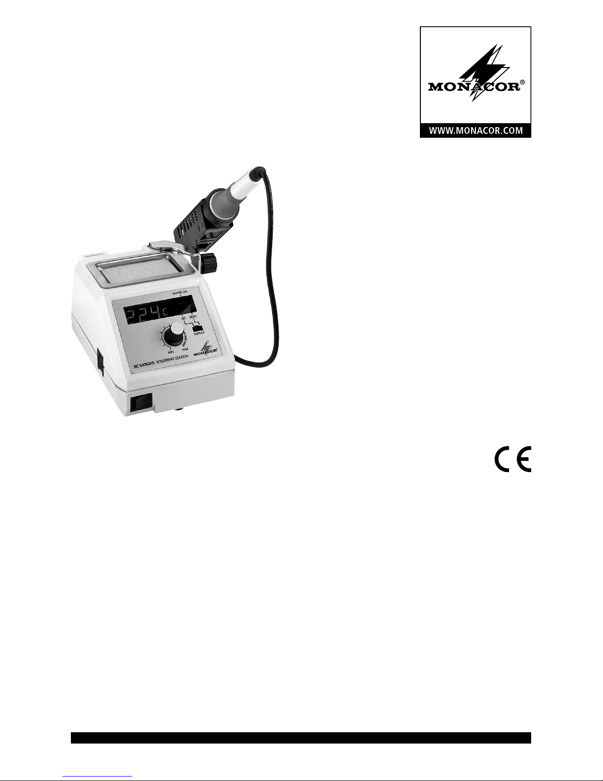
SIC-530ROHS
Bestell-Nr. • Order No. 31.1640
Lötstation
Soldering Station

ELECTRONICS FOR SPECIALISTS ELECTRONICS FOR SPECIALISTS ELECTRONICS FOR SPECIALISTS ELECTRONICS FOR SPECIALISTS
2
Deutsch ..........Seite 4
English ...........Page 6
Français ..........Page 8
Italiano...........Pagina 10
Nederlands .......Pagina 12
Español ..........Página 14
Português ........Página 16
Dansk ............Sida 18
Svenska ..........Sidan 20
Suomi............Sivulta 22
3
4
3
9
8
1
2
6 75
10 1211
4
Deutsch
Lötstation
Diese Anleitung richtet sich an Benutzer mit
Grundkenntnissen in der Löttechnik. Bitte lesen
Sie die Anleitung vor dem Betrieb gründlich durch
und heben Sie sie für ein späteres Nachlesen auf.
Auf der ausklappbaren Seite 3 finden Sie alle
beschriebenen Bedienelemente und Anschlüsse.
1 Übersicht der Anschlüsse und
Bedienelemente
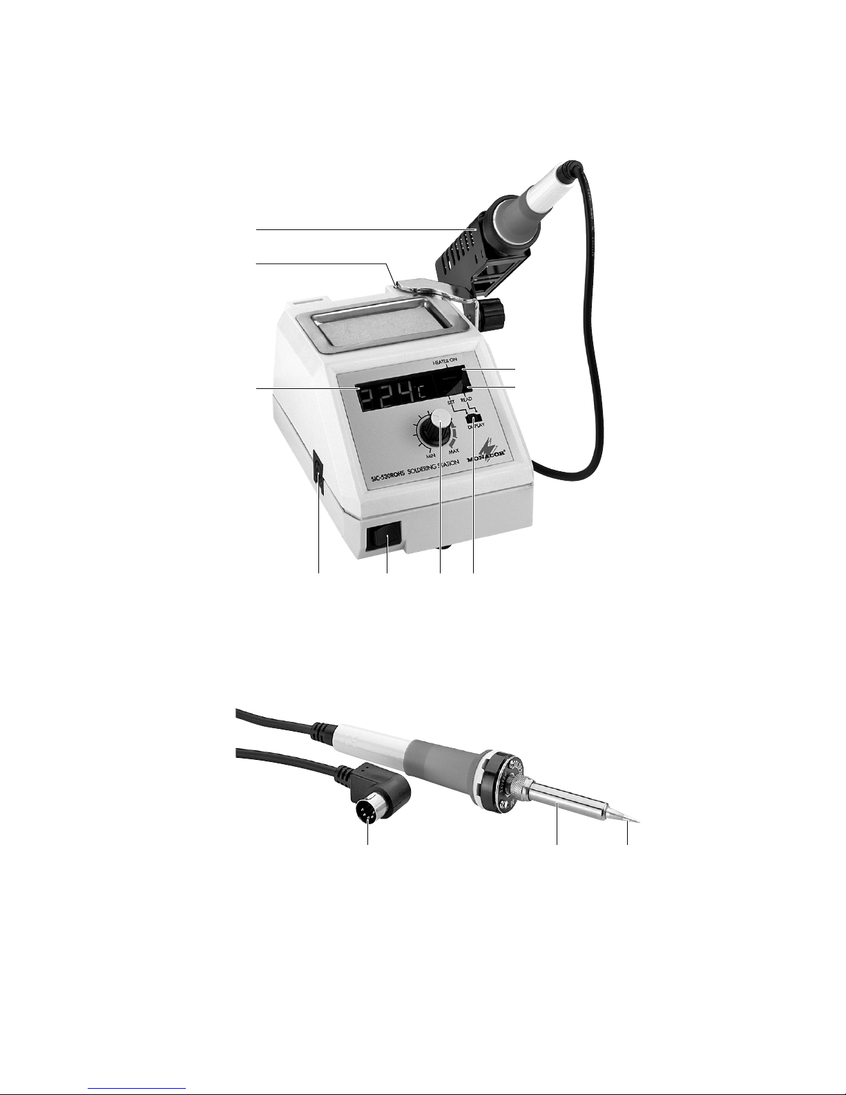
1 Lötkolbenhalterung
2 Steckschlitz für die Lötkolbenhalterung
3 LED-Display zur Temperaturanzeige
4 5-polige DIN-Buchse zum Anschluss des Löt-
kolbens
5
Kippschalter zum An- und Ausschalten der
Lötstation
6 Drehregler zum Einstellen der Löttemperatur
7
Schalter DISPLAY zum Umschalten des Temperatur-Displays (3);
Stellung SET: Display zeigt die gewünschte,
mit dem Drehregler eingestellte Lötspitzentemperatur
an
Stellung READ: Display zeigt die aktuelle Löt-
spitzentemperatur an
8 Heizanzeige HEATER ON
9 Zustandsanzeige des Temperatur-Displays
Steht der Schalter DISPLAY (7) auf Stellung SET,
leuchtet das linke Feld SET: Das Display zeigt
die gewünschte Lötspitzentemperatur an.
Steht der Schalter DISPLAY auf Stellung READ,
leuchtet das rechte Feld READ: Das Display
zeigt die aktuelle Lötspitzentemperatur an.
10 5-poliger Winkel-DIN-Stecker des Lötkolbens
11 Schraubhülse des Lötkolbens
12 Lötspitze
2 Hinweise für den
sicherenGebrauch
Das Gerät entspricht allen relevanten Richtlinien
der EU und ist deshalb mit gekennzeichnet.
WARNUNG Das Gerät wird mit lebensgefähr-
licher Netzspannung versorgt.
Nehmen Sie deshalb niemals selbst
Eingriffe am Gerät vor. Durch unsachgemäßes Vorgehen besteht
die Gefahr eines elektrischen
Schlages.
•
Das Gerät ist nur zur Verwendung im Innenbereich geeignet. Schützen Sie es vor Tropf- und
Spritzwasser, hoher Luftfeuchtigkeit und Hitze
(zulässiger Einsatztemperaturbereich 0 – 40 °C).
•
Stellen Sie keine mit Flüssigkeit gefüllten Gefäße z. B. Trinkgläser, auf das Gerät.
•
Das Gerät gehört nicht in Kinderhände!
•
Um einen Brand oder andere Beschädigungen
durch den heißen Lötkolben zu vermeiden, den
Lötkolben nur in der Lötkolbenhalterung oder
auf eine feuerfeste Unterlage ablegen.
•
Den aufgeheizten Lötkolben nur am Kolbengriff anfassen. Bei Berührung der Metallteile
des Kolbens besteht Verbrennungsgefahr. Nach
Beendigung der Arbeit den Lötkolben nur an
der Luft abkühlen lassen, auf keinen Fall mit
Wasser abschrecken.
•
Ziehen Sie sofort den Netzstecker aus der Steckdose,
1. wenn sichtbare Schäden am Gerät oder am
Netzkabel vorhanden sind,
2. wenn nach einem Sturz oder Ähnlichem der
Verdacht auf einen Defekt besteht,
3. wenn Funktionsstörungen auftreten.
Geben Sie das Gerät in jedem Fall zur Reparatur
in eine Fachwerkstatt.
•
Ein beschädigtes Netzkabel darf nur durch eine
Fachwerkstatt ersetzt werden.
•
Ziehen Sie den Netzstecker nie am Kabel aus
der Steckdose, fassen Sie immer am Stecker an.
•
Für die Reinigung des Gehäuses keine scharfen
Reinigungsmittel oder Chemikalien verwenden.
Das Gerät auf keinen Fall in Flüssigkeit tauchen
bzw. Flüssigkeit eindringen lassen.
•
Wird das Gerät zweckentfremdet, nicht richtig
angeschlossen, falsch bedient oder nicht fachgerecht repariert, kann keine Haftung für daraus resultierende Sach- oder Personenschäden
5
Deutsch
und keine Garantie für das Gerät übernommen
werden.
Soll das Gerät endgültig aus dem Betrieb genommen werden, übergeben
Sie es zur umweltgerechten Entsorgung
einem örtlichen Recyclingbetrieb.
3 Inbetriebnahme
WICHTIG! Zur Vermeidung von Überhitzungs-
schäden darf die Lötstation nicht ohne Lötspitze
betrieben werden.
1)
Den Lötkolben mit der Lötstation verbinden.
Dazu den Stecker (10) des Lötkolbens in die
Buchse (4) stecken.
2)
Die Lötkolbenhalterung (1) in den Steckschlitz(2) schieben.
3)
Die Lötstation mit dem Netzstecker an eine
Steckdose (230 V/ 50 Hz) an schlie ßen.
4) Zum Einschalten des Gerätes den Kippschalter
(5) drücken. Die digitale Temperaturanzeige (3)
und die Heizanzeige HEATER ON (8) leuchten
auf.
5)
Den Schalter DISPLAY (7) auf Position SET schieben. Das linke Feld SET der Zustandsanzeige (9)
leuchtet auf. Mit dem Drehregler (6) die Temperatur (160 – 480 °C) einstellen. Die gewünschte
Temperatur wird vom Display (3) angezeigt.
6)
Anschließend den Schalter DISPLAY nach rechts
auf Position READ schieben. Das rechte Feld
READ der Zustandsanzeige leuchtet auf. Bei
dieser Schalterstellung zeigt das Display die aktuelle Aufheiztemperatur bzw. Lötspitzentemperatur an. Während der Aufheizzeit leuchtet
die Heizanzeige HEATER ON. Sie erlischt, wenn
die eingestellte Temperatur erreicht ist.
7)
Zum Ausschalten des Gerätes den Kippschalter
(5) drücken.
4 Lötspitze ersetzen
1) Vor dem Auswechseln der Lötspitze das Gerät
mit dem Kippschalter (5) ausschalten und den
Netzstecker ziehen. Die Schraubhülse (11) und
die Lötspitze (12) auf Raumtemperatur abkühlen lassen.
2)
Die Schraubhülse mit den Fingern vom Kolbenrohr abschrauben.
3)
Das Kolbenrohr von eventuellen Oxid-Rückständen säubern. Beim Herausblasen der OxidTeilchen aus dem Rohr muss für entsprechenden Augenschutz gesorgt werden.
4)
Die Lötspitze ersetzen (z. B. durch Lötspitzen
der MONACOR-Serie SIT-5..ROHS) und die
Schraubhülse mit den Fingern festdrehen. Um
das Heizelement nicht zu beschädigen, darf die
Schraubhülse nicht zu fest angezogen werden.
5 Hinweise zum richtigen Löten
1. Vor dem Betrieb den festen Sitz der Lötspitze
kontrollieren.
2.
Die Lötspitze immer sauber halten und – besonders vor dem Ausschalten der Lötstation– mit
ausreichend Lötzinn versehen.
3. Vor dem Löten die zu lötenden Teile säubern.
4.
Zum Schutz von Lötstation und Lötspitze sollte
das Gerät nicht über längere Zeit bei Temperaturen von 400 °C und mehr betrieben werden.
6 Reinigung der Lötstation
Vor dem Reinigen muss die Lötstation ausgeschaltet und vom Netz getrennt werden!
Das Gehäuse der Lötstation und der Kolbengriff
können mit einem leicht angefeuchtetem Tuch
und einer kleinen Menge flüssigen Reinigungsmittels gesäubert werden. Scharfe Reinigungsmittel oder Chemikalien dürfen nicht verwendet
werden. Beim Reinigen darauf achten, dass keine
Flüssigkeit in das Gerät eindringt!
7 Technische Daten
Heizleistung: . . . . . . . . . . 48 W
Stromversorgung: . . . . . . 230 V/ 50 Hz
Leistungsaufnahme: . . . . max. 55 VA
Elektronische
Temperaturregelung:
. . . . 160 – 480 °C
Abmessungen (B × H × T): . 120 × 95 × 180 mm
(ohne Kolbenhalterung)
Gewicht: . . . . . . . . . . . . . 1,9 kg
Ersatzlötkolben: . . . . . . . SIA-548ROHS
Ersatzlötspitzen:
. . . . . . . SIT-501ROHS
SIT-503ROHS
SIT-504ROHS
SIT-505ROHS
Änderungen vorbehalten.
Diese Bedienungsanleitung ist urheberrechtlich für
MONACOR ® INTERNATIONAL GmbH & Co. KG geschützt.
Eine Reproduktion für eigene kommerzielle Zwecke – auch
auszugsweise – ist untersagt.
6
English
Soldering station
These operating instructions are intended for users
with basic knowledge in soldering technology.
Please read the instructions carefully prior to
operating the unit and keep them for later reference.
All operating elements and connections de-
scribed can be found on the fold-out page 3.
1 Operating Elements and
Connections
1 Soldering iron support
2 Slot to slide in the soldering iron support
3 LED temperature display
4 5-pole DIN jack to connect the soldering iron
5 Toggle switch to switch the soldering station
on and off
6
Rotary control to set the soldering temperature
7
Switch DISPLAY to change the temperature
display (3);
Position SET: Display shows the desired
soldering tip temperature set
with the rotary control
Position READ: Display shows the current sol-
dering tip temperature
8 LED indicator HEATER ON
9 Status indicator of the temperature display
When the switch DISPLAY (7) is in the position
SET, the left field SET will light up: The display
will show the desired soldering tip temperature.
When the switch DISPLAY is in the positon
READ, the right field READ will light up: The
display will show the current soldering tip
temperature.
10 Angled 5-pole DIN plug of the soldering iron
11 Screw sleeve of the soldering iron
12 Soldering tip
2 Safety Notes
This unit corresponds to all relevant directives of
the EU and is therefore marked with .
WARNING
The unit uses dangerous mains
voltage. Leave servicing to skilled
personnel only. Inexpert handling
may result in electric shock.
•
The unit is suitable for indoor use only. Protect
it against dripping water and splash water, high
air humidity and heat (admissible ambient temperature range 0 – 40 °C).
•
Do not place any vessels filled with liquid, e. g.
drink ing glasses, on the unit.
•
Keep the unit away from children!
•
To prevent a fire or any other damage, always
put the hot soldering iron into its holder or on
a fire-proof surface.
•
Only seize the hot soldering iron by its handle.
Never touch the metal parts of the hot soldering
iron – risk of burning! After operation, allow the
soldering iron to cool down in air only, never
use water to quench it.
•
Immediately disconnect the mains plug from
the mains socket if
1. there is visible damage to the unit or to the
mains cable,
2. a defect might have occurred after the unit
was dropped or suffered a similar accident,
3. there are malfunctions.
The unit must in any case be repaired by skilled
personnel.
•
A damaged mains cable must be replaced by
skilled personnel only.
•
Never pull the mains cable to disconnect the
mains plug from the mains socket; always seize
the plug.
•
For cleaning the housing, do not use any aggressive detergents or chemicals. Never immerse the station in liquid and make sure that
no liquid will enter the station.
•
No guarantee claims for the unit and no liability
for any resulting personal damage or material
damage will be accepted if the unit is used for
other purposes than originally intended, if it is
not correctly connected or operated, or if it is
not repaired in an expert way.
•
Important for UK Customers!
The wires in this mains lead are coloured in
accord ance with the following code:
blue = neutral; brown = live
As the colours of the wires in the mains lead
of this appliance may not correspond with the
coloured markings identifying the terminals in
your plug, proceed as follows:
1.
The wire which is coloured blue must be connected to the terminal in the plug which is
mark ed with the letter N or coloured black.
7
English
2. The wire which is coloured brown must be
connected to the terminal which is marked
with the letter L or coloured red.
If the unit is to be put out of operation
definitively, take it to a local recycling
plant for a disposal which is not harmful
to the environment.
3 Setting into Operation
IMPORTANT! To avoid damage by overheating,
do not operate the soldering station without soldering tip.
1)
Connect the soldering iron to the soldering
station: Connect the plug (10) of the soldering
iron to the jack (4).
2)
Slide the soldering iron support (1) into the
slot (2).
3)
Connect the mains plug of the soldering
station to a socket (230 V/ 50 Hz).
4)
To switch on the station, press the toggle switch
(5). The digital temperature display (3) and the
LED indicator HEATER ON (8) will light up.
5) Slide the switch DISPLAY to the position SET.
The left field SET of the status indicator (9) will
light up. Use the rotary control (6) to set the
temperature (160 – 480 °C). The display (3) will
show the temperature desired.
6) Then slide the switch DISPLAY to the right to
the position READ. The right field READ of the
status indicator will light up; the display will
show the current heat-up temperature or temperature of the soldering tip. The LED indicator
HEATER ON will light while the soldering tip is
being heated up. It will extinguish as soon as
the temperature adjusted has been reached.
7)
To switch off the station, press the toggle
switch (5).
4 Replacement ofthe SolderingTip
1) Prior to replacing the soldering tip, switch off
the station with the toggle switch (5) and disconnect the station from the mains. Allow the
screw sleeve (11) and the soldering tip (12) to
cool down to room temperature.
2) Use your fingers to unscrew the screw sleeve
from the soldering iron tube.
3)
Remove any oxide residues from the soldering iron tube. While blowing oxide particles
out of the tube, provide a corresponding eye
protection.
4)
Replace the soldering tip (e. g. by soldering tips
of the MONACOR series SIT-5..ROHS) and use
your fingers to fasten the screw sleeve. Make
sure not to fasten the screw sleeve too tightly;
the heating element may be damaged.
5 Notes on Correct Soldering
1. Prior to operation, ensure a tight fit of the soldering tip.
2. Always keep the soldering tip clean and make
sure that sufficient soldering tin is applied to
the tip, especially before switching off the soldering station.
3. Prior to soldering, remove any impurities from
the parts to be soldered.
4.
To protect the soldering station and the soldering
tip, do not operate the station at temperatures
of 400 °C or higher for a longer period of time.
6 Cleaning the Soldering Station
Prior to cleaning, always switch off the soldering station and disconnect it from the
mains! For cleaning the housing of the soldering
station and the handle of the soldering iron, use
a damp cloth and a small quantity of cleaning
fluid. Do not use any aggressive detergents or
chemicals. When cleaning, make sure that no
fluid will enter the unit!
7 Specifications
Heating power: . . . . . . . . 48 W
Power supply: . . . . . . . . . 230 V/ 50 Hz
Power consumption: . . . . 55 VA max.
Electronic temperature
control:
. . . . . . . . . . . . . . 160 – 480 °C
Dimensions (W × H × D): . . 120 × 95 × 180 mm
(w/o soldering iron
support)
Weight:
. . . . . . . . . . . . . 1.9 kg
Replacement
soldering iron:
. . . . . . . . . SIA-548ROHS
Replacement
soldering tips:
. . . . . . . . . SIT-501ROHS
SIT-503ROHS
SIT-504ROHS
SIT-505ROHS
Subject to technical modification.
All rights reserved by MONACOR ® INTERNATIONAL
GmbH & Co. KG. No part of this instruction manual
may be reproduced in any form or by any means for any
commercial use.

8
Français
Station de soudure
Cette notice s’adresse aux utilisateurs avec des
connaissances techniques de base en soudage.
Veuillez lire la présente notice avec attention
avant le fonctionnement et conservez-la pour
pouvoir vous y reporter ultérieurement.
Vous trouverez sur la page 3, dépliable, les
éléments et branchements décrits.
1 Eléments et branchements
1 Support du fer à souder
2
Fente de positionnement du support du fer
à souder
3 Affichage LED de la température
4
Prise DIN 5 pôles pour brancher le fer à souder
5 Interrupteur à bascule Marche /Arrêt
6 Potentiomètre rotatif, réglage de la tempéra-
ture de soudure
7 Interrupteur DISPLAY : commutation de l’affi-
chage de la température (3)
Position SET: l’affichage indique la tempé-
rature voulue de la panne,
réglée avec le po ten tiomètre(6)
Position READ: l’affichage indique la tempé-
rature réelle de la panne
8 Témoin de chauffage HEATER ON
9 Témoin d’état de l’affichage de température
Si l’interrupteur DISPLAY (7) est sur la position
SET, le champ gauche SET s’allume, l’affichage
indique la tem pérature voulue de la panne.
Si l’interrupteur DISPLAY est sur la position
READ, le champ droit READ s’allume, l’affichage indique la température réelle de la
panne.
10 Fiche DIN coudée 5 pôles du fer à souder
11 Embout du fer à souder
12 Panne
2 Conseils d’utilisation etdesécurité
Cet appareil répond à toutes les directives
nécessaires de l’Union européenne et porte donc
le symbole .
AVERTISSEMENT
Cet appareil est alimenté par
une tension dangereuse. Ne
touchez jamais l’intérieur
de l’appareil car, en cas de
mauvaise manipulation, vous
pourriez subir une décharge
électrique.
•
L’appareil n’est conçu que pour une utilisation
en intérieur. Protégez-le des éclaboussures, de
tout type de projections d’eau, de l’humidité et
de la chaleur (température ambiante admissible
0 – 40 °C).
•
En aucun cas, vous ne devez poser d’objet
contenant du liquide ou un verre sur l’appareil.
•
Tenez-le hors de la portée des enfants !
•
Pour éviter tout incendie ou dégât par un fer
à souder chaud, posez-le uniquement sur son
support ou sur une surface ignifugée.
•
Ne saisissez le fer à souder chaud que par sa
poi gnée. En manipulant la partie métallique
du fer, vous risquez de vous brûler. Une fois
vos travaux terminés, laissez refroidir le fer à
l’air libre; en aucun cas, n’utilisez pas de l’eau
pour le refroidir.
•
Débranchez immédiatement la fiche du secteur
lorsque :
1.
des dommages visibles apparaissent sur l’appareil ou sur le cordon secteur,
2.
après une chute ou un cas similaire, vous
avez un doute sur l’état de l’appareil,
3. des dysfonctionnements apparaissent.
Faites toujours appel à un technicien spécialisé
pour effectuer les réparations.
•
Tout cordon secteur endommagé doit être remplacé impérativement par un technicien spécialisé.
•
Ne débranchez jamais l’appareil en tirant sur le
cordon secteur, tenez-le toujours par la fiche.
•
Pour nettoyer le boîtier, n’utilisez pas de détergents forts ou de produits chimiques. En
aucun cas, vous ne devez plonger l’appareil
dans un liquide ou y faire entrer du liquide.
•
Nous déclinons toute responsabilité en cas de
dommages corporels ou matériels résultants
si l’appareil est utilisé dans un but autre que
 Loading...