

Page 1
BEDIENUNGSANLEITUNG
INSTRUCTION MANUAL
MODE D’EMPLOI
ISTRUZIONI PER L’USO
GEBRUIKSAANWIJZING
HANDLEIDING
MANUAL DE INSTRUCCIONES
BRUGSANVISNING
BRUKSANVISNING
KÄYTTÖOHJE
SCHWARZWEISS-MONITOR
BLACK WHITE MONITOR
CDM-2002
Best.-Nr. 19.3930
®
Page 2
2
Vor der Montage ...
Wir wünschen Ihnen viel Spaß mit Ihrem neuen Gerät
von MONACOR. Dabei soll Ihnen diese Bedienungsanleitung helfen, alle Funktionsmöglichkeiten kennenzulernen. Die Beachtung der Anleitung vermeidet außerdem Fehlbedienungen und schützt Sie und Ihr Gerät vor
eventuellen Schäden durch unsachgemäßen Gebrauch.
Den deutschen Text finden Sie auf den Seiten 4–5.
Prior to Mounting ...
We wish you much pleasure with your new unit by
MONACOR. With these operating instructions you will
be able to get to know all functions of the unit. By following these instructions false operations will be avoided,
and possible damage to you and your unit due to improper use will be prevented.
You will find the English text on the pages 4–5.
D
A
CH
GB
Avant toute installation ...
Nous vous remercions d’avoir choisi un appareil
MONACOR et vous souhaitons beaucoup de plaisir à
l’utiliser. Cette notice a pour objectif de vous aider à
mieux connaître les multiples facettes de l’appareil et à
vous éviter toute mauvaise manipulation.
La version française se trouve pages 6–7.
Prima del montaggio ...
Vi auguriamo buon divertimento con il Vostro nuovo apparecchio MONACOR. Le istruzioni per l’uso Vi possono
aiutare a conoscere tutte le possibili funzioni. E
rispettando quanto spiegato nelle istruzioni, evitate di
commettere degli errori, e così proteggete Voi stessi, ma
anche l’apparecchio, da eventuali rischi per uso improprio.
Il testo italiano lo potete trovare alle pagine 6–7.
F
B
CH
I
Voordat u inschakelt ...
Wij wensen u veel plezier met uw nieuw toestel van
MONACOR. Met behulp van bijgaande gebruiksaanwijzing kunt u alle functiemogelijkheden leren kennen.
Door deze instructies op te volgen zal een slechte werking vermeden worden, en zal een eventueel letsel aan
uzelf en schade aan uw toestel tengevolge van onzorgvuldig gebruik worden voorkomen.
U vindt de nederlandstalige tekst op de pagina’s 8–9.
Antes del montaje …
Tenemos de agradecerle el haber adquirido un equipo
MONACOR y le deseamos un agradable uso. Este
manual quiere ayudarle a conocer las multiples facetas
de este equipo y evitar cualquier uso inadecuado.
La versión española se encuentra en las páginas 8–9.
NL
B
E
Inden De tænder for apparatet ...
Tillykke med det nye system fra MONACOR. Nærværende betjeningsvejledning giver kendskab til alle
systemets funktioner. Hvis instruktionerne følges nøje,
undgås fejlbetjening, og mulig skade på brugeren eller
systemet som følge af fejlbetjening vil kunne forhindres.
Den danske tekst finder De på side 10–11.
Före montering …
Vi önskar dig mycket nöje med din nya enheten från
MONACOR. Om du först läser instruktionerna kommer
du att glädje av enheten under lång tid. Kunskap om alla
funktioner kan bespara dig mycket besvär med enheten
i framtiden.
Du finner den svenska texten på sidan 10–11.
DK
S
Ennen kuin kytket …
Jotta hyötyisit mahdollisimman paljon uudesta
MONACOR-järjestelmästäsi, lue huolella tämä käyttöohje. Tällöin saat hyödynnettyä kaikki järjestelmän
tarjoamat toiminnot, ja vältät virhetoiminnot ja niiden
mahdollisesti aiheuttamat vahingot itsellesi tai järjestelmällesi.
Löydät suomenkielisen ohjeen sivuilta 12.
FIN
Page 3
3
1234567891011 1213
V-SIZE H-SIZE V-HOLD H-HOLD BRIGHT CONTRAST SHARPNESS VOLUME
SCAN VIDEO
AB
ABOVER
UNDER
®
CDM-2002
V-SIZE H-SIZE V-HOLD H-HOLD BRIGHT CONTRAST SHARPNESS VOLUME
SCAN VIDEO
AB
A
B
OVER
UNDER
14 15 16 17 18 19 20 21 22
➀
➁
➂➃
VIDEO A
IN OUT
VIDEO BAC IN
IN OUT
AUDIO
DC-REST.
OFF ON
OUTIN
V-LIN.
Page 4

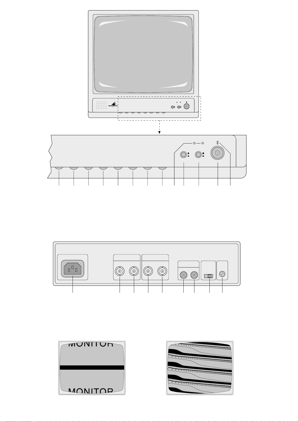
Bitte klappen Sie die Seite 3 heraus. Sie sehen
dann immer die beschriebenen Bedienelemente
und Anschlüsse.
1 Übersicht der Bedienelemente und
Anschlüsse
1.1 Frontseite
1 Regler für die Bildhöhe
2 Regler für die Bildbreite
3 Regler für die Bildsynchronisation
4 Regler für die Zeilensynchronisation
5 Helligkeitsregler
6 Kontrastregler
7 Bildschärferegler
8 Lautstärkeregler
9 Kontroll-LEDs zeigen den eingeschalteten Video-
kanal an (Kamera Aoder B)
10 Umschalter für die Bilddarstellung
Taste nicht gedrückt:
das Bild wird etwas vergrößert, die Randbereiche des Bildes sind jedoch nicht sichtbar
Taste gedrückt:
Bildschirm wird nicht ganz ausgeschrieben,
d.h. es erscheinen schwarze Bildränder, dafür sind jedoch die Randbereiche sichtbar
11 Videokanal-Umschalter
Taste nicht gedrückt:
Kanal A ist eingeschaltet
Taste gedrückt:
Kanal B ist eingeschaltet
12 Ein-/Ausschalter
13 Betriebsanzeige
1.2 Anschlußfeld auf der Rückseite
14 Buchse AC IN für die beiliegende Netzleitung
zum Anschluß an 230V~/50Hz
15 BNC-Buchse für den Videoeingang des Kanals A
zum Anschluß einer Überwachungskamera bzw.
eines Kamera-Umschalters oder Video-Splitters
16 BNC-Buchse für den Videoausgang des KanalsA
zum Anschluß eines weiteren Monitors oder
eines Videorecorders
17 BNC-Buchse für den Videoeingang des Kanals B
18 BNC-Buchse für den Videoausgang des KanalsB
19 Cinch-Buchse für den Audioeingang zum An-
schluß eines Kameramikrofons oder eines
Videorecorders
20 Cinch-Buchse für den Audioausgang zum
Anschluß eines weiteren Monitors oder eines
Videorecorders
21
Schalter DC-RESTfür die interne Pegelanpassung
Position OFF
Überwachungsbereich gering ausgeleuchtet
Position ON
Überwachungsbereich hell ausgeleuchtet
22 Trimmpotentiometer , nur für den Service in einer
Fachwerkstatt bestimmt
2 Hinweise für den sicheren Gebrauch
Dieses Gerät entspricht der Richtlinie für elektromagnetische Verträglichkeit 89/336/EWG und der Niederspannungsrichtlinie 73/23/EWG.
Das Gerät wird mit lebensgefährlicher Netzspannung (230 V~) versorgt. Nehmen Sie deshalb niemals selbst Eingriffe im Gerät vor. Durch unsachgemäßes Vorgehen besteht die Gefahr eines
elektrischen Schlages. Außerdem erlischt beim
Öffnen des Gerätes jeglicher Garantieanspruch.
Beachten Sie auch unbedingt die folgenden Punkte:
●
Vorsicht! Die Bildröhre ist luftleer. Bei mechanischer Beschädigung besteht Implosionsgefahr
und Verletzungsgefahr durch herumfliegende
Glassplitter.
●
Das Gerät ist nur zur Verwendung im Innenbereich geeignet. Schützen Sie es vor Feuchtigkeit
und Hitze (zulässiger Einsatztemperaturbereich
0–40°C).
●
Die in dem Gerät entstehende Wärme muß durch
Luftzirkulation abgegeben werden. Decken Sie
darum die Lüftungslöcher des Gehäuses nicht mit
irgendwelchen Gegenständen ab.
●
Stecken Sie nichts durch die Lüftungslöcher! Dabei
kann es zu einem elektrischen Schlag kommen.
●
Nehmen Sie das Gerät nicht in Betrieb bzw. ziehen Sie sofort den Netzstecker aus der Steckdose, wenn:
1. sichtbare Schäden am Gerät oder an der Netzanschlußleitung vorhanden sind,
2. nach einem Sturz oder ähnlichem der Verdacht
auf einen Defekt besteht,
3. Funktionsstörungen auftreten.
Geben Sie das Gerät in jedem Fall zur Reparatur
in eine Fachwerkstatt.
●
Ziehen Sie den Netzstecker nie an der Zuleitung
aus der Steckdose.
●
Verwenden Sie für die Reinigung nur ein trockenes, weiches Tuch, auf keinen Fall Chemikalien
oder Wasser.
●
Wird das Gerät zweckentfremdet, falsch angeschlossen, nicht richtig bedient oder nicht fachgerecht repariert, kann für eventuelle Schäden keine
Haftung übernommen werden.
●
Soll das Gerät endgültig aus dem Betrieb genommen werden, übergeben Sie es zur Entsorgung
einem örtlichen Recyclingbetrieb.
3 Einsatzmöglichkeiten
Der Monitor ist speziell für den Einsatz in VideoÜberwachungsanlagen konzipiert. Durch die automatische Netzspannungsanpassung (100V–240V;
50/ 60 Hz) und durch die automatische VideonormUmschaltung (CCIR/ EIA) ist das Gerät in Ländern
mit verschiedenen Normen einsetzbar.
Mehrere Monitore lassen sich zu einer Monitorkette verbinden, um so an verschiedenen Stellen
oder durch mehrere Personen eine Überwachung
zu ermöglichen. Über das integrierte Tonteil läßt
sich mit einem Kameramikrofon der Bereich auch
akustisch überwachen.
Please unfold page3. Then you can always see
the operating elements and connections described.
1 Operating Elements and Connections
1.1 Front panel
1 Picture height control
2 Picture width control
3 Control for vertical synchronization
4 Control for horizontal synchronization
5 Brightness control
6 Contrast control
7 Sharpness control
8 Volume control
9 Control LEDs indicating the video channel
switched on (camera Aor B)
10 Push-button switch for picture representation
Switch is not pressed:
The picture is slightly enlarged, however, its
edges are not visible.
Switch is pressed:
The picture does not fill the entire screen, i.e.
there are black borders around the picture
but the edges of the picture itself are visible.
11 Push-button switch for video channels
Switch is not pressed:
Channel Ais switched on
Switch is pressed:
Channel B is switched on
12 On/off switch
13 Operating indication
1.2 Connections at the rear panel
14 Jack AC IN for the supplied mains cable for con-
nection to 230V~/50Hz
15 BNC jack for the video input of channel A to
connect a monitoring camera, camera selector
switch or a video splitter
16 BNC jack for the video output of channel A to
connect a further monitor or a video recorder
17 BNC jack for the video input of channel B
18 BNC jack for the video output of channel B
19 Phono jack for the audio input to connect a
camera microphone or a video recorder
20 Phono jack for the audio output to connect a fur-
ther monitor or a video recorder
21 DC-REST switch for internal level adjustment
Position OFF
Monitoring area slightly illuminated
Position ON
Monitoring area brightly illuminated
22 Trimming potentiometer, only for servicing car-
ried out by authorized personnel
2 Safety Notes
This unit corresponds to the directive for electromagnetic compatibility 89/336/EEC and to the low voltage directive 73/23/EEC.
The unit is supplied with hazardous mains voltage
(230V~). Leave servicing to authorized personnel
only. Inexpert handling may cause an electric
shock hazard. Furthermore, any guarantee claim
will expire if the unit has been opened.
Please observe the following items in any case:
●
Caution! The picture tube is vacuous. In case of
mechanical damage, there is an implosion hazard
and scattered glass may cause injuries.
●
The unit is suitable for indoor use only. Protect it
against humidity and heat (admissible ambient
temperature range 0–40°C).
●
The heat generated in the unit must be carried off
by air circulation. Therefore, do not cover the air
vents of the housing with any objects.
●
Do not insert anything through the air vents! An
electric shock may result.
●
Do not operate the unit and immediately disconnect it from the mains socket
1. if there is visible damage to the unit or to the
mains cable,
2. if a defect might have occurred after the unit
was dropped or suffered a similar accident,
3. if malfunctions occur.
In any case the unit must be repaired by authorized personnel.
●
Never pull the mains cable to disconnect the unit
from the mains socket.
●
For cleaning only use a dry, soft cloth, by no
means chemicals or water.
●
If the unit is used for other purposes than originally
intended, if it is not connected or operated in the
correct way or not repaired by authorized personnel, no liability for any damage will be accepted.
●
If the unit is to be put out of operation permanently, take it to a local recycling plant for disposal.
●
Important for U.K. Customers!
The wires in this mains lead are coloured in accordance with the following code:
green/yellow = earth
blue = neutral
brown = live
As the colours of the wires in the mains lead of this
appliance may not correspond with the coloured
markings identifying the terminals in your plug,
proceed as follows:
1. The wire which is coloured green and yellow
must be connected to the terminal in the plug
which is marked with the letter E or by the earth
symbol , or coloured green or green and yel-
low.
2. The wire which is coloured blue must be connected to the terminal which is marked with the
letter N or coloured black.
3. The wire which is coloured brown must be connected to the terminal which is marked with the
letter L or coloured red.
Warning
-
This appliance must be earthed.
4
GB
D
A
CH
Page 5
4 Aufstellung und Anschluß des Gerätes
Der Monitor kann als freistehendes Tischgerät
verwendet oder mit Hilfe des Montagerahmens
CDM-2002R von MONACOR in ein Rack (482mm/
19") einsetzt werden.
Alle Anschlüsse nur bei ausgeschaltetem Gerät vornehmen bzw. verändern.
1) Den Videoeingang des Kanals A (15) über ein
75-Ω-Koaxialkabel an den Ausgang der Überwachungkamera bzw. des Kamera-Umschalters
oder des Video-Splitters anschließen.
Ist eine zweite Kamera oder ein zweiter Überwachungskanal vorhanden, den Eingang des
Kanals B (17) entsprechend anschließen.
2) Sollen zur parallelen Überwachung mehrere
Monitore aufgestellt werden, immer den Videoausgang (16 bzw. 18) über ein 75-Ω-Koaxialkabel mit dem Videoeingang (15 bzw. 17) des nächsten Monitors verbinden.
An die Buchsen VIDEO OUT läßt sich aber
auch alternativ je ein Videorecorder anschließen,
um gleichzeitig die Bilder aufzuzeichnen.
Wichtig: Keine unbenutzten Kabel oder Stecker
in den Buchsen OUT stecken lassen. Die automatische Impedanzumschaltung für die Eingangsbuchsen arbeitet sonst nicht korrekt.
3) Ist die Kamera mit einem Mikrofon und entsprechendem Vorverstärker ausgestattet, das Tonsignal über ein abgeschirmtes Kabel auf die CinchBuchse AUDIO IN (19) geben. An diese Buchse
kann aber auch der Audioausgang eines Videorecorders angeschlossen werden.
Das Tonsignal kann über die Buchse AUDIO
OUT (20) zu einem parallelgeschalteten Monitor
oder zu einem Videorecorder weitergeleitet werden.
4) Zum Schluß das beiliegende Netzkabel zuerst in
die Buchse AC IN (14) und dann in eine Steckdose stecken.
5 Bedienung
1) Den Monitor mit dem Ein-/Ausschalter (12) einschalten. Die rechteckige LED (13) leuchtet als
Betriebsanzeige, und nach einigen Sekunden
wird der Bildschirm hell.
2) Nachdem alle Geräte der Überwachungsanlage
eingeschaltet wurden, mit dem Umschalter
VIDEO (11)die Kamera (A oder B) bzw. den
Videokanal wählen.
3) Ist der Überwachungsbereich hell ausgeleuchtet,
den Schiebeschalter DC-REST (21) auf der
Geräterückseite in die Position ON stellen. Bei
einer geringen Ausleuchtung den Schalter in die
Position OFF schieben.
4) Mit dem Helligkeitsregler BRIGHT (5) und dem
Kontrastregler CONTRAST (6) ein optimales Bild
einstellen.
5) Wenn das Bild durchlaufen sollte (Abb. 3), mit
dem Regler V-HOLD (3) ein stabiles Bild einstellen.
6) Wenn die Zeilen nicht synchronisiert werden
(Abb. 4), mit dem Regler H-HOLD (4) ein stabiles
Bild einstellen.
7) Mit dem Regler SHARPNESS (7) die Bildschärfe
justieren.
8) Mit dem Umschalter SCAN (10) die Bilddarstellung wählen:
Position OVER (Taste nicht gedrückt)
Das Bild wird etwas vergrößert. Dafür sind
die Randbereiche des Bildes nicht sichtbar.
Position UNDER (Taste gedrückt)
Der Bildschirm wird nicht ganz ausgeschrieben, d. h. es erscheinen schwarze Bildränder, dafür sind jedoch die Randbereiche
sichtbar.
Mit dem Regler V-SIZE (1) kann die Bildbreite
und mit dem Regler H-SIZE (2) die Bildhöhe entsprechend der gewählten Bilddarstellung noch
feiner angepaßt werden. Die Bildbreite und -höhe
dabei gleichzeitig justieren, damit die Bildgeometrie nicht verändert wird (runde Objekte dürfen
nicht oval erscheinen). Als Einstellhilfe rasten die
Regler in der Mittelstellung ein, wodurch die
Standardeinstellung markiert ist.
9) Mit dem Regler VOLUME (8) die Lautstärke einstellen. Wird kein Tonsignal auf den Monitor gegeben, den Regler auf Minimum stellen (entgegen dem Uhrzeigersinn drehen).
6 Technische Daten
Bildröhre: . . . . . . . . . . . . . . . sichtbare Diagonale
47cm (20")
Auflösung: . . . . . . . . . . . . . . > 900 Linien
Linearität: . . . . . . . . . . . . . . . hor. 10%, vert. 10%
Synchronisation, automatisch umschaltend
CCIR: . . . . . . . . . . . . . . . . h. 15625Hz, v. 50Hz
EIA: . . . . . . . . . . . . . . . . . . h. 15750Hz, v. 60Hz
2 x Videoeingang: . . . . . . . . 1Vss (BNC)
Impedanzumschaltung: . . . . automatisch
75Ω/hochohmig
2 x Video-Durchschleifausg.: 1Vss (BNC)
1 x Audioeingang: . . . . . . . . 300mV (Cinch)
1 x Audio-Durchschleifausg.: 300mV (Cinch)
Audio-Ausgangsleistung: . . . 1 W
Einsatztemperatur: . . . . . . . . 0–40°C
Stromversorgung: . . . . . . . . 100 – 240 V~ /
50–60Hz
Leistungsaufnahme: . . . . . . 50VA
Abmessungen (B x H x T): . . 445 x 442 x 380mm
Gewicht: . . . . . . . . . . . . . . . . 17,7 kg
Laut Angaben des Herstellers.
Änderungen vorbehalten.
3 Applications
The monitor has especially been designed for application in video monitoring systems. Due to the automatic mains voltage adjustment (100V–240V; 50/
60 Hz) and the automatic video standard changeover (CCIR/EIA), the unit can be used in countries
with different standards.
Several monitors can be connected in series to
allow monitoring at different places or by several
persons. Via the integrated audio module, the area
can also be monitored acoustically with a camera
microphone.
4 Installation and Connection
of the Monitor
The monitor can be used as a table top unit or can
be installed into a rack (482 mm / 19") by means of
the mounting frame CDM-2002R by MONACOR.
Connections must only be made or changed with the
unit switched off.
1) Connect the video input of channel A (15) to the
output of the monitoring camera, of the camera
selector switch or the video splitter via a 75 Ω
coaxial cable.
In case of a second camera or a second monitoring channel, connect the input of channel B
(17) accordingly.
2) If several monitors are to be set up for parallel
monitoring, always connect the video output (16
or 18) to the video input (15 or 17) of the next
monitor via a 75Ω coaxial cable.
Alternatively, one video recorder each may be
connected to the jacks VIDEO OUT for simultaneous recording of the pictures.
Important: Do not leave unused cables or
connectors in the OUT jacks, otherwise the automatic impedance switching for the input jacks will
not work correctly.
3) If the camera is provided with a microphone and
a corresponding pre-amplifier, feed the audio signal to the phono jack AUDIO IN (19) via a shield-
ed cable. It is also possible to connect the audio
output of a video recorder to this jack.
Via the jack AUDIO OUT(20), the audio signal
can be passed on to a monitor connected in
parallel or to a video recorder.
4) Finally plug the supplied mains cable first into
jack AC IN (14) and then into a mains socket.
5 Operation
1) Switch on the monitor with the on/off switch (12).
The rectangular LED (13) will light up as operation indication, and after a few seconds the
screen will become bright.
2) After all units of the monitoring system have been
switched on, select the camera (A or B) or the
video channel by means of the push-button
switch VIDEO (11).
3) If the monitoring area is brightly illuminated, set
the sliding switch DC-REST (21) at the rear side
of the housing to the position ON. In case of a
slight illumination, slide the switch to the position
OFF.
4) Adjust an optimum picture with the brightness
control BRIGHT (5) and the CONTRAST control (6).
5) If the picture rolls up or down the screen (fig. 3),
adjust a stable picture with the control V-HOLD (3).
6) If the lines are not synchronized (fig. 4), adjust a
stable picture with the control H-HOLD (4).
7) Adjust the sharpness of the picture with the
SHARPNESS control (7).
8) Select the picture representation with the pushbutton switch SCAN (10):
Position OVER (switch not pressed)
The picture is slightly enlarged but its edges
are not visible.
Position UNDER (switch is pressed)
The picture does not fill the entire screen,
i.e. there are black borders around the picture but the edges of the picture itself are
visible.
With the V-SIZE control (1) the picture width and
with the H-SIZE control (2) the picture height can
be adjusted more precisely according to the selected picture representation. Adjust the picture
width and height simultaneously so that the geometry of the picture is not changed (round objects
must not appear oval). To facilitate the adjustment, the controls lock in mid-position, thus
marking the standard adjustment.
9) Adjust the volume with the VOLUME control (8).
If no audio signal is fed to the monitor, set the
control to its minimum position (turn in counterclockwise direction).
6 Specifications
Picture tube: . . . . . . . . . . . . . visible diagonal
47cm (20")
Resolution: . . . . . . . . . . . . . . > 900 lines
Linearity: . . . . . . . . . . . . . . . hor. 10%, vert. 10%
Synchronization, automatic change-over
CCIR: . . . . . . . . . . . . . . . . h. 15625Hz, v. 50Hz
EIA: . . . . . . . . . . . . . . . . . . h. 15750Hz, v. 60Hz
2 x video input: . . . . . . . . . . . 1Vpp (BNC)
Impedance switching: . . . . . automatically
75Ω/high impedance
2 x video feed-through output: 1Vpp (BNC)
1 x audio input: . . . . . . . . . . . 300mV (phono)
1 x audio feed-through output: 300mV (phono)
Audio output power: . . . . . . . 1 W
Ambient temperature: . . . . . 0 – 40 °C
Power supply: . . . . . . . . . . . 100 – 240 V~/
50–60Hz
Power consumption: . . . . . . 50 VA
Dimensions (W x H x D): . . . 445 x 442 x 380 mm
Weight: . . . . . . . . . . . . . . . . . 17.7kg
According to the manufacturer.
Subject to technical change.
5
GB
D
A
CH
Page 6

Ouvrez le présent livret page 3 de manière à
visualiser les éléments et branchements.
1 Eléments et branchements
1.1 Face avant
1 Potentiomètre de réglage pour la hauteur
d’image
2 Potentiomètre de réglage de la largeur d’image
3 Potentiomètre de réglage de la synchronisation
d’image
4 Potentiomètre de réglage de la synchronisation
de lignes
5 Potentiomètre de réglage de la luminosité
6 Potentiomètre de réglage du contraste
7 Potentiomètre de réglage de la netteté d’image
8 Potentiomètre de réglage de volume
9 LEDs de contrôle: indiquent le canal vidéo bran-
ché (caméra Aou B)
10 Sélecteur du mode d’affichage
touche non enfoncée:
l’image est agrandie, mais les contours de
l’image ne sont pas visibles
touche enfoncée:
des bords d’image noirs apparaissent, les
contours sont visibles
11 Sélecteur canal vidéo
touche non enfoncée: canal Asélectionné
touche enfoncée: canal B sélectionné
12 Interrupteur Marche/Arrêt
13 Témoin de fonctionnement
1.2 Face arrière – Prises
14 Prise AC IN pour le cordon secteur livré, à bran-
cher à une prise 230V ~ /50 Hz
15 Prise BNC pour l’entrée vidéo du canal A: permet
de brancher une caméra de surveillance, un
sélecteur de caméras ou un répartiteur vidéo
16 Prise BNC pour la sortie vidéo du canal A: per-
met de brancher un autre moniteur ou un
magnétoscope
17 Prise BNC pour l’entrée vidéo du canal B
18 Prise BNC pour la sortie vidéo du canal B
19 Prise RCA pour l’entrée audio: permet de bran-
cher un microphone de caméra ou un magnétoscope
20 Prise RCA pour la sortie audio: permet de bran-
cher un autre moniteur ou un magnétoscope
21 Interrupteur DC-REST: adaptation interne du
niveau
position OFF:
zone de surveillance faiblement éclairée
positon ON:
zone de surveillance très éclairée.
22 Potentiomètre régulation: ne doit être activé que
par un technicien habilité
2 Conseils d’utilisation
Le monitor répond à la norme européenne 89/336/
CEE relative à la compatibilité électromagnétique et
à la norme 73/ 23 / CEE portant sur les appareils à
basse tension.
Cet appareil est alimenté par une tension en
230V~. Ne touchez jamais l’intérieur de l’appareil,
car, en cas de mauvaise manipulation, vous pourriez subir une décharge électrique mortelle. En
outre, l’ouverture de l’appareil rend tout droit à la
garantie caduque.
Respectez scrupuleusement les points suivants:
●
Attention: le tube est vide d’air. En cas de dommage mécanique, il peut imploser et vous blesser
en projetant des débris de verre.
●
Cet appareil n’est conçu que pour une utilisation en
intérieur. Protégez-le de la chaleur et de l’humidité
(température d’utilisation admissible 0–40°C).
●
La chaleur dégagée par l’appareil doit être évacuée par une circulation correcte de l’air. En
aucun cas, les ouïes de ventilation ne doivent être
obturées.
●
Ne faites rien tomber dans les ouïes de ventilation, vous pourriez vous électrocuter.
●
Ne le faites pas fonctionner et débranchez-le
immédiatement lorsque:
1. des dommages apparaissent sur l’appareil ou
sur le cordon secteur,
2. après une chute ou un cas similaire vous avez
un doute sur l’état du appareil,
3. des dysfonctionnements apparaissent.
Seul un technicien habilité peut effectuer les réparations.
●
Ne le débranchez jamais en tirant directement sur
le cordon secteur.
●
Nous déclinons toute responsabilité en cas de
dommage si l’appareil est utilisé dans un but autre
que celui pour lequel il a été conçu, s’il n’est pas
correctement utilisé ou branché ou n’est pas réparé par un téchnicien habilité.
●
Pour le nettoyer, utilisez un chiffon sec et souple,
en aucun cas, de produits chimiques ou d’eau.
●
Lorsque l’appareil est définitivement retiré du circuit de distribution, vous devez le déposer dans
une usine de recyclage adaptée.
3 Possibilités d’utilisation
Le moniteur CDM-2002 est spécialement conçu
pour une utilisation dans des centrales de surveillance. L’adaptation automatique de tension (100–
240V , 50/60Hz), et la commutation automatique de
norme vidéo CCIR/EIA, permet d’utiliser cet appareil dans des pays relevant de normes différentes.
Il est possible de brancher plusieurs moniteurs
pour surveiller plusieurs lieux ou par plusieurs personnes. Le système micro intégré permet d’effectuer également une surveillance acoustique.
Vi preghiamo di aprire completamente la pagina 3.
Così vedrete sempre gli elementi di comando e i
collegamenti descritti.
1 Elementi di comando e collegamenti
1.1 Lato frontale
1 Regolatore altezza immagine
2 Regolatore larghezza immagine
3 Regolatore sincronizzazione dell’immagine
4 Regolatore sincronizzazione delle righe
5 Regolatore luminosità
6 Regolatore contrasto
7 Regolatore fuoco
8 Regolatore volume
9 Led di controllo: indicano il canale attivo (video-
camera A o B)
10 Commutatore rappresentazione immagine
Tasto non premuto:
immagine leggermente ingrandita, la zona
periferica non è visibile
Tasto premuto:
lo schermo non è sfruttato completamente; si
vedono strisce nere sui bordi, ma le zone
periferiche sono completamente visibili
11 Selettore canale video:
Tasto non premuto: è attivo il canale A
Tasto premuto: è attivo il canale B
12 Interruttore on/off
13 Spia di funzionamento
1.2 Collegamenti sul lato posteriore
14 Presa AC IN per il cavo rete in dotazione per
230V~/50 Hz
15 Presa BNC per l’ingresso video del canale A, per
il collegamento di una videocamera di sorveglianza o di un selettore o splitter video
16 Presa BNC per l’uscita video del canale A, per il
collegamento di un altro monitor o di un videoregistratore
17 Presa BNC per l’ingresso video del canale B
18 Presa BNC per l’uscita video del canale B
19 Presa cinch per l’ingresso audio, per il collega-
mento di un microfono di camera o di un videoregistratore
20 Presa cinch per l’uscita audio, per il collega-
mento di un altro monitor o di un videoregistratore
21 Interruttore DC-REST per l’adattamento interno
del livello
Posizione OFF
Zona da sorvegliare poco illuminata
Posizione ON
Zona da sorvegliare bene illuminata
22 Potenziometro di regolazione; solo per il servizio
di assistenza di un laboratorio specializzato.
2 Avviso di sicurezza
Quest’apparecchio corrisponde alla direttiva CE
89/ 336 / CEE sulla compatibilità elettromagnetica e
73/23/CEE per apparecchi a bassa tensione.
L’apparecchio funziona con tensione di rete di
230V~. Non intervenire mai al suo interno; la manipolazione scorretta può provocare delle scariche pericolose. Se l’apparecchio viene aperto,
cessa ogni diritto di garanzia.
Durante l’uso si devono osservare assolutamente i
seguenti punti:
●
Attenzione! Il tubo catodico è a vuoto. Nel caso di
danneggiamento meccanico sussiste il pericolo di
implosione e di essere feriti dalle schegge di
vetro.
●
Lo strumento è previsto solo per l’uso all’interno di
locali asciutti. Proteggerlo dall’umidità e dal calore
(temperatura d’impiego ammessa fra 0°C e 40°C).
●
Dev’essere garantita la libera circolazione dell’aria per dissipare il calore che viene prodotto all’in-
terno dell’apparecchio. Non coprire in nessun modo le fessure di aerazione.
●
Non inserire oggetti nelle fessure di aerazione e
non farci cadere niente. Altrimenti si potrebbe provocare una scarica elettrica.
●
Non mettere in funzione l’apparecchio e staccare
subito la spina rete se:
1. l’apparecchio o il cavo rete presentano dei danni visibili;
2. dopo una caduta o dopo eventi simili sussiste il
sospetto di un difetto;
3. l’apparecchio non funziona correttamente.
Per la riparazione rivolgersi sempre ad una officina competente.
●
Staccare il cavo rete afferrando la spina, senza tirare il cavo.
●
Per la pulizia usare solo un panno asciutto e morbido; non impiegare in nessun caso prodotti chimici o acqua.
●
Nel caso di uso improprio, di impiego scorretto, di
collegamenti sbagliati o di riparazione non a regola d’arte non si assume nessuna responsabilità
per eventuali danni.
●
Se si desidera eliminare l’apparecchio definitivamente, consegnarlo per lo smaltimento ad un’istituzione locale per il riciclaggio.
3 Possibilità d’impiego
Il monitor è previsto specialmente per l’impiego in
impianti di sorveglianza con videocamere. Grazie
all’adattamento automatico alla tensione di rete
(100V–240V; 50/60Hz) ed alla commutazione
automatica della norma video (CCIR/EIA), il monitor
può essere impiegato in paesi con norme diverse.
Si possono collegare più monitor per formare una
catena di monitor. In tal modo è possibile una sorveglianza in luoghi diversi oppure con più persone.
Con il gruppo audio integrato è possibile anche la
sorveglianza acustica servendosi di un microfono
sulla videocamera.
6
I
F
B
CH
Page 7
4 Installation et branchement
Il est possible de poser le moniteur sur une table ou
de le placer dans un rack au standard (482mm/19")
grâce à l’étrier de montage CDM-2002R de
MONACOR (en option).
Tous les branchements ne doivent être effectués ou
modifiés que lorsque le moniteur est débranché.
1) Reliez l’entrée vidéo du canal A (15) via un câble
coaxial 75 Ω à la sortie de la caméra / au sélecteur de caméras/au séquenceur.
Si une seconde caméra ou un second canal
de transmission existe, branchez l’entrée su canal B (17).
2) Si plusieurs moniteurs doivent être branchés en
parallèle, reliez toujours la sortie vidéo (16/ 18)
via un câble coaxial 75Ω à l’entrée vidéo (15/17)
du moniteur suivant.
Il est également possible de brancher un magnétoscope aux prises VIDEO OUT pour enregistrer simultanément.
Important: Ne laissez pas de cordon inutilisé
branché sur les prises OUT. La commutation automatique d’impédance des prises d’entrée ne
fonctionnerait pas correctement.
3) Si la caméra est dotée d’un microphone et d’un
préamplificateur correspondant, appliquez le signal via un câble blindé, à la prise RCAAUDIO IN
(19). La sortie audio d’un magnétoscope peut
également être branchée à cette prise.
Le signal sonore peut être dirigé via la prise
AUDIO OUT (20) vers un moniteur branché en
parallèle ou un magnétoscope.
4) Reliez maintenant le cordon secteur à la prise AC
IN (14) puis ce dernier au secteur.
5 Fonctionnement
1) Allumez le moniteur avec l’interrupteur marche /
arrêt (12): la LED (13) s’allume, elle sert de
témoin de fonctionnement; quelques secondes
après, l’écran est clair.
2) Une fois que tous les appareils du système de
surveillance sont branchés, sélectionnez la
caméra (A ou B) ou le canal vidéo avec le sélecteur VIDEO (11).
3) Si la zone de surveillance dispose d’un éclairage
très important, mettez le potentiomètre DCREST (21) de la face arrière, sur la position ON.
En cas d’éclairage plus faible, mettez-le sur OFF .
4) Utilisez les réglages BRIGHT (5) et CONTRAST
(6) pour régler respectivement la luminosité et le
contraste.
5) Si l’image saute (voir schéma 3), utilisez le
réglage V-HOLD (3) pour stabiliser l’image.
6) Si les lignes ne sont pas synchronisées (schéma
4), utilisez le réglage H-HOLD (4).
7) Avec le réglage SHARPNESS (7), réglez la netteté de l’image.
8) Utilisez le réglage SCAN (10) pour sélectionner
le mode d’affichage:
position OVER (touche non enfoncée)
l’image est agrandie, les contours de l’image ne sont pas visibles
position UNDER (touche enfoncée)
des bords d’image noirs apparaissent, mais
les contours sont visibles
Utilisez les réglages V-SIZE (1) et H-SIZE (2)
pour régler la largeur et la hauteur d’image en
fonction du mode d’affichage sélectionné. Effectuez les modifications nécessaires de telle sorte
que la géométrie de l’image ne soit pas modifiée
(par exemple, les objets ronds ne doivent pas
être ovales). Pour vous aider, notez que les
réglages s’enclenchent en position médiane pour
marquer le réglage standard.
9) Réglez le volume (8); si le moniteur ne reçoit pas
de signal, mettez le réglage VOLUME (8) sur le
minimum (tournez-le dans le sens inverse des
aiguilles d’une montre).
6 Caractéristiques techniques
Tubes: . . . . . . . . . . . . . . . . . diagonale visible
47cm (20")
Résolution: . . . . . . . . . . . . . . > 900 lignes
Linéarité: . . . . . . . . . . . . . . . hor. 10%, vert. 10%
Synchronisation, commutable automatiquement
CCIR: . . . . . . . . . . . . . . . . h. 15625Hz, v. 50Hz
EIA: . . . . . . . . . . . . . . . . . . h. 15750Hz, v. 60Hz
2 x entrée vidéo: . . . . . . . . . 1 Vcc (BNC)
Commutation d’impédance: . automatique 75 Ω/
haute impédance
2 x sortie vidéo insert: . . . . . 1 Vcc (BNC)
1 x entrée audio: . . . . . . . . . 300mV (RCA)
1 x sortie audio insert: . . . . . 300mV (RCA)
Puissance de sortie audio: . . 1W
Température d’utilisation: . . . 0–40 °C
Alimentation: . . . . . . . . . . . . 100–240V~/
50–60Hz
Consommation: . . . . . . . . . . 50VA
Dimensions (L x H x P): . . . . 445 x 442 x 380 mm
Poids: . . . . . . . . . . . . . . . . . . 17,7 kg
D’après les données du constructeur.
Tout droit de modification réservé.
4 Collocazione e collegamento
del monitor
Il monitor può essere usato come modello da tavolo,
oppure può essere montato in un rack (482mm/19")
con l’aiuto del telaio CDM-2002R della MONACOR.
Eseguire o modificare i collegamenti solo con il
monitor spento.
1) Collegare l’ingresso video del canale A (15) con
l’uscita della videocamera, del selettore o del
video splitter, mediante un cavo coassiale 75Ω.
Se è presente una seconda videocamera o un
secondo canale di sorveglianza, collegare anche
l’ingresso del canale B (17).
2) Se si desidera collocare più monitor per una sorveglianza parallela, collegare l’uscita video (16 e
18) con l’ingresso video (15 e 17) del monitor
successivo, mediante un cavo coassiale 75Ω.
Alle prese VIDEO OUT può essere collegato
anche un videoregistratore per registrare nello
stesso tempo l’immagine.
Importante: Non lasciare cavi o connettori inutilizzati nelle prese OUT. Altrimenti la commutazione automatica dell’impedenza per le prese di
entrada non lavora correttamente.
3) Se la videocamera è equipaggiata con un microfono con preamplificatore, portare il segnale
audio nella presa cinch AUDIO IN (19) servendosi di un cavo schermato. La stessa presa serve
anche per il collegamento dell’uscita audio di un
videoregistratore.
Il segnale audio può essere inoltrato verso un
monitor collegato in parallelo o verso un videoregistratore tramite la presa AUDIO OUT(20).
4) Alla fine inserire il cavo rete nella presa AC IN
(14) e quindi in una presa di rete.
5 Funzionamento
1) Accendere il monitor con l’interruttore on/off
POWER (12). Si accende il led rettangolare (13),
e dopo alcuni secondi lo schermo si illumina.
2) Dopo aver acceso tutti gli apparecchi dell’impianto di sorveglianza, scegliere la videocamera (A
o B) tramite il selettore VIDEO (11).
3) Se la zona da sorvegliare è illuminata bene,
spostare l’interruttore DC-REST (21) sul retro in
posizione ON. Se l’illuminazione è scarsa, posizionarlo su OFF.
4) Impostare l’immagine ottimale mediante i regolatori di luminosità BRIGHT (5) e di contrasto CONTRAST (6).
5) Nel caso l’immagine dovesse scorrere sullo
schermo (fig. 3), stabilizzarla con il regolatore VHOLD (3).
6) Se le righe non risultano sincronizzate (fig. 4),
stabilizzare l’immagine con il regolatore H-HOLD
(4).
7) Regolare il fuoco con il regolatore SHARPNESS
(7).
8) Con il commutatore SCAN (10) selezionare la
rappresentazione dell’immagine:
Posizione OVER (tasto non premuto)
immagine leggermente ingrandita, la zona
periferica non è visibile
Posizione UNDER (tasto premuto)
lo schermo non è sfruttato completamente;
si vedono strisce nere sui bordi, ma le zone
periferiche sono completamente visibili
Con il regolatore V-SIZE (1) si può regolare la
larghezza dell’immagine e con H-SIZE (2) la sua
altezza. Eseguire questi aggiustamenti sempre
insieme per non cambiare la geometria dell’immagine (gli oggetti rotondi non devono prendere
una forma ovale). La posizione standard è quella
centrale, individuabile dallo scatto
9) Con il regolatore VOLUME (8) regolare il volume.
In assenza di un segnale audio, posizionarlo sul
minimo (girarlo in senso antiorario).
6 Dati tecnici
Tubo catodico: . . . . . . . . . . . diagonale visibile
47cm (20")
Risoluzione: . . . . . . . . . . . . . > 900 righe
Linearità; . . . . . . . . . . . . . . . orizz. 10%, vert. 10%
Sincronizzazione, a commutazione automatica
CCIR: . . . . . . . . . . . . . . . . or. 15625 Hz, v. 50Hz
EIA: . . . . . . . . . . . . . . . . . or. 15750 Hz, v. 60Hz
2 x ingresso video: . . . . . . . . 1 Vpp (BNC)
Commutazione impedenza: . automatica, 75 Ω/
alta impedenza
2 x uscita video passante: . . 1 Vpp (BNC)
1 x ingresso audio: . . . . . . . . 300mV (cinch)
1 x uscita audio passante: . . 300mV (cinch)
Potenza uscita audio: . . . . . 1W
Temperatura d’impiego
ammessa: . . . . . . . . . . . . . . 0–40 °C
Alimentazione: . . . . . . . . . . . 100–240V~/
50–60Hz
Assorbimento: . . . . . . . . . . . 50 VA
Dimensioni (L x H x P): . . . . 445 x 442 x 380mm
Peso: . . . . . . . . . . . . . . . . . . 17,7kg
Dati forniti dal costruttore.
Con riserva di modifiche tecniche.
7
I
F
B
CH
Page 8

Vouw bladzijde 3 helemaal open, zodat u steeds
een overzicht hebt van de bedieningselementen
en de aansluitingen.
1 Bedieningselementen en
aansluitingen
1.1 Frontpaneel
1 Regelaar voor de beeldhoogte
2 Regelaar voor de beeldbreedte
3 Regelaar voor de beeldsynchronisatie
4 Regelaar voor de lijnsynchronisatie
5 Helderheidsregelaar
6 Contrastregelaar
7 Regelaar voor de beeldscherpte
8 Volumeregelaar
9 Controle-LED’s voor aanduiding van het inge-
schakelde videokanaal (camera Aof B)
10 Keuzeschakelaar voor de beeldweergave
Toets niet ingedrukt:
het beeld wordt iets vergroot, de randzones
van het beeld zijn evenwel niet zichtbaar
Toets ingedrukt:
het beeldscherm wordt niet volledig opgevuld, d.w.z. dat er rond het beeld zwarte randen verschijnen, maar de randzones van het
beeld zijn nu wel zichtbaar
11 Keuzeschakelaar om het videokanaal te selecte-
ren
Toets niet ingedrukt: Kanaal Ais ingeschakeld
Toets ingedrukt: Kanaal B is ingeschakeld
12 POWER-schakelaar
13 POWER-LED
1.2 Aansluitveld aan de achterzijde
van het toestel
14 AC IN-jack om meegeleverd netsnoer aan te
sluiten op 230V~/50 Hz
15 BNC-jack voor de video-ingang van het kanaal A
voor aansluiting van een bewakingscamera
resp. een camera-omschakelaar of video-splitter
16 BNC-jack voor de video-uitgang van het kanaal
A voor aansluiting van een bijkomende monitor
of een videorecorder
17 BNC-jack voor de video-ingang van het kanaal B
18 BNC-jack voor de video-uitgang van het kanaal B
19 Cinch-jack voor de audio-ingang voor aansluiting
van een cameramicrofoon of een videorecorder
20 Cinch-jack voor de audio-uitgang voor aansluit-
ing van een bijkomende monitor of een videorecorder
21 DC-REST-schakelaar voor de interne niveaure-
geling
OFF-stand
het te bewaken terrein is weinig verlicht
ON-stand
het te bewaken terrein is goed verlicht
22 Trimpotentiometer, enkel bedoeld voor gebruik
in een werkplaats
2 Veiligheidsvoorschriften
Dit toestel is in overeenstemming met de EU-richtlijn
89/ 336/ EEG voor elektromagnetische compatibiliteit en 73/23/EEG voor toestellen op laagspanning.
De netspanning (230 V~) van het toestel is levensgevaarlijk. Open het toestel niet, want door
onzorgvuldige ingrepen loopt u het risico van een
elektrische schok. Bovendien vervalt elke garantie
bij het eigenhandig openen van het toestel.
Let eveneens op het volgende:
●
Opgelet! De beeldbuis is vacuüm. Bij mechanische beschadiging bestaat er gevaar voor implosie en risico op verwondingen door rondvliegende
glassplinters.
●
Het toestel is enkel geschikt voor gebruik binnenshuis. Vermijd uitzonderlijk warme plaatsen en
plaatsen met een hoge vochtigheid (toegestaan
omgevingstemperatuurbereik: 0–40°C).
●
De warmte die in het toestel ontstaat, moet door
ventilatie afgevoerd worden. Zorg er daarom voor
dat u de ventilatieopeningen van de behuizing met
geen enkel voorwerp afdekt.
●
Zorg ervoor dat u niets in de ventilatieopeningen
steekt! Er bestaat immers gevaar voor elektrische
schokken.
●
Schakel het toestel niet in resp. trek onmiddellijk
de stekker uit het stopcontact, wanneer:
1. het toestel of het netsnoer zichtbaar beschadigd zijn,
2. er een defect zou kunnen optreden nadat het
toestel bijvoorbeeld gevallen is,
3. het toestel slecht functioneert.
Het toestel moet in elk geval hersteld worden door
een gekwalificeerd vakman.
●
Trek de stekker nooit met het snoer uit het stopcontact.
●
Gebruik voor de reiniging uitsluitend een droge,
zachte doek. Gebruik in geen geval chemicaliën
of water.
●
In geval van ongeoorloofd of verkeerd gebruik,
verkeerde aansluiting, foutieve bediening of herstelling door een niet-gekwalificeerd persoon vervalt de garantie bij eventuele schade.
●
Wanneer het toestel definitief uit bedrijf genomen
wordt, bezorg het dan voor verwerking aan een
plaatselijk recyclagebedrijf.
3 Toepassingen
De monitor is speciaal ontworpen voor gebruik in
videobewakingssystemen. Dankzij de automatische
aanpassing aan de netspanning (100V–240V;
50/60Hz) en de automatische omschakeling van de
videonorm (CCIR/ EIA) is het toestel bruikbaar in
landen met verschillende normen.
U kunt meerdere monitoren serieel met elkaar
verbinden, zodat op verschillende plaatsen of door
meer dan één persoon bewaking mogelijk is. Via de
ingebouwde audiocomponent kunt u met een cameramicrofoon het terrein ook akoestisch bewaken.
Abrir el manual página 3 para visualizar los elementos y las conexiones.
1 Elementos y conexiones
1.1 Panel delantero
1 Potenciómetro de ajuste para la altura de la ima-
gen
2 Potenciómetro de ajuste para la anchura de la
imagen
3 Potenciómetro de ajuste para la sincronización
de la imagen
4 Potenciómetro de ajuste de la sincronización de
las líneas
5 Potenciómetro de ajuste de la luminosidad
6 Potenciómetro de ajuste del contraste
7 Potenciómetro de ajuste de la claridad de la ima-
gen
8 Potenciómetro de ajuste del volumen
9 Diodos de controlo: indican el canal vídeo
conectado (cámara Ao B)
10 Selector del modo de pantalla
tecla no apretada:
la imagen está aumentada un poco, pero los
bordes de la imagen no se ven.
tecla apretada:
bordes negros aparecen en la pantalla, pero
la imagen está completamente visible.
11 Selector canal vídeo
tecla no apretada:
canal A seleccionado
tecla apretada:
canal B seleccionado
12 Interruptor On/Off
13 Testigo de funcionamiento
1.2 Panel de conexiones trasero
14 Toma AC IN para el cable de red entregado, a
conectar a una toma de red 230V~/50 Hz
15 Toma BNC para la entrada vídeo del canal A:
permite de conectar una cámara de vigilancia,
un selector de cámara o un repartidor vídeo
16 Toma BNC para la salida vídeo del canal A: per-
mite de conectar otro monitor o un grabador de
vídeo
17 Toma BNC para la entrada vídeo del canal B
18 Toma BNC para la salida vídeo del canal B
19 T oma RCApara la entrada audio: permite conec-
tar un micrófono de una cámara o un grabador
de vídeo
20 T oma RCApara la salida audio: permite conectar
otro monitor o un grabador de vídeo
21 Interruptor DC-REST: adaptación interna del
nivel
posición OFF:
zona de vigilancia con poca luz
posición ON:
zona de vigilancia con mucha luz
22 Potenciómetro de compensación: sólo puede
estar activado por un técnico habilitado
2 Consejos de utilización
El monitor cumple la norma europea 89/ 336/ CEE
relativa a la compatibilidad electromagnética y a la
norma 73/23/CEE sobre los aparatos a baja tensión.
Este aparato está alimentado por una tensión de
230V~. No tocar nunca dentro el aparato, se podría recibir una descarga eléctrica mortal. Además la abertura del aparato anula todo tipo de
garantía.
Respetar en todo caso los puntos siguientes:
●
Atención: el tubo de imagen está vacío de aire,
en caso de daños mecánicos, puede implotar y
dañaros proyectando cascos de vidrio de la pantalla.
●
Este aparato sólo se puede usar en interior. Protegerlo de la humedad y del calor (temperatura de
utilización admisible 0–40°C).
●
El calor generado por el aparato tiene que estar
disipado por una corriente de aire correcta. En
ningún caso, las ranuras de ventilación no pueden
estar obstruidas.
●
¡No hacer caer nada dentro las ranuras de ventilación! Se podría recibir una descarga eléctrica
mortal.
●
No hacerlo funcionar y desconectarlo inmediatamente de la red cuando:
1. daños aparecen sobre el aparato o sobre el
cable de red,
2. después una caída o accidente parecido, el
aparato pueda tener un defecto,
3. disfunciones aparecen.
Sólo un técnico habilitado puede efectuar las
reparaciones.
●
No desconectarlo nunca estirando el cable de red.
●
Declinamos toda responsabilidad en caso de
daños si el aparato está utilizado por un uso diferente de su concepción, si no está correctamente
conectado, utilizado o no está reparado por un
técnico habilitado.
●
Para limpiarlo, utilizar un trapo seco y suave, en
ningún caso, productos químicos o agua.
●
Cuando el aparato está definitivamente retirado
del circuito de distribución, se tiene que depositar
dentro una fábrica de reciclaje adaptada.
3 Posibilidades de utilización
El monitor CDM-2002 está previsto especialmente
para una utilización dentro centrales de vigilancia
vídeo. La adaptación automática de tensión de red
(100–240V , 50/60Hz) y la conmutación automática
de norma vídeo (CCIR/ EIA), permiten utilizar este
aparato dentro países con normas diferentes.
Es posible conectar varios monitores para una
cadena de monitores para vigilar lugares diferentes
o por varias personas. El módulo del sonido integ-
8
E
NL
B
Page 9
4 Het toestel opstellen en aansluiten
De monitor kan als vrijstaand tafelmodel gebruikt of
met behulp van het montageframe CDM-2002R van
MONACOR in een rack (482 mm/ 19") ingebouwd
worden.
De in- en uitgangen mogen enkel aangesloten en
gewijzigd worden, wanneer het toestel uitgeschakeld is.
1) Sluit de video-ingang van het kanaal A (15) via
een 75 Ω-coaxkabel aan op de uitgang van de
bewakingscamera resp. de camera-omschakelaar of de video-splitter.
Indien er een tweede camera of een tweede
bewakingskanaal beschikbaar is, sluit dan de
ingang van het kanaal B (17) overeenkomstig aan.
2) Wenst u voor de parallelle bewaking meer dan
één monitor op te stellen, verbind de video-uitgang (16 resp. 18) dan steeds via een 75Ω-mo-
nitor met de video-ingang (15 resp. 17) van de
volgende monitor.
Op elk van de jacks VIDEO OUT kunt u echter
ook een videorecorder aansluiten om tegelijk
beelden op te nemen.
Belangrijk: Laat geen ongebruikte kabels of
stekkers in de OUT-jacks steken. Anders functioneert de automatische omschakeling van de
impedantie voor de ingangsjacks niet correct.
3) Indien de camera met een microfoon en een aangepaste voorversterker uitgerust is, stuurt u het
geluidssignaal via een afgeschermde kabel naar
de cinch-jack AUDIO IN (19). Op deze jack kunt u
echter ook de audio-uitgang van een videorecorder aansluiten.
Het geluidssignaal kan via de jack AUDIO
OUT (20) naar een parallelgeschakelde monitor
of naar een videorecorder gestuurd worden.
4) Ten slotte verbindt u het meegeleverde netsnoer
eerst met de jack AC IN (14) en vervolgens plugt
u het snoer in een stopcontact.
5 Werking
1) Schakel met de POWER-schakelaar (12) de
monitor in. De rechthoekige LED (13) licht op, en
enkele seconden later ook het beeldscherm.
2) Nadat alle apparatuur van het bewakingssysteem ingeschakeld zijn, selecteert u met de keuzeschakelaar VIDEO (11) de camera (A of B)
resp. het videokanaal.
3) Indien het te bewaken terrein goed verlicht is,
plaatst u de schuifschakelaar DC-REST (21) aan
de achterzijde van het toestel in de ON-stand. Bij
een zwakke verlichting schuift u de schakelaar in
de OFF-stand.
4) Stel met de helderheidsregelaar BRIGHT (5) en
de contrastregelaar CONTRAST (6) een optimaal beeld in.
5) Indien het beeld zou doorlopen (figuur 3), stel
dan met de regelaar V-HOLD (3) een stabiel
beeld in.
6) Wanneer er geen lijnsynchronisatie uitgevoerd
wordt (figuur 4), stel dan met de regelaar
H-HOLD (4) een stabiel beeld in.
7) Regel met de SHARPNESS-regelaar (7) de
beeldscherpte bij.
8) Selecteer met de SCAN-schakelaar (10) de
gewenste beeldweergave:
OVER-stand (toets is niet ingedrukt)
Het beeld wordt iets vergroot. De randzones van het beeld zijn evenwel niet zichtbaar.
UNDER-stand (toets ingedrukt)
Het beeldscherm wordt niet volledig opgevuld, d.w.z. dat er rond het beeld zwarte
randen verschijnen, maar de randzones
van het beeld zijn nu wel zichtbaar.
Met de regelaars V-SIZE (1) en H-SIZE (2) kan
de beeldbreedte resp. de beeldhoogte in functie
van de geselecteerde beeldweergave nog fijner
afgeregeld worden. Regel beeldbreedte en
beeldhoogte hierbij gelijktijdig af, zodat de beeldgeometrie niet gewijzigd wordt (ronde voorwerpen mogen niet ovaal weergegeven worden). Als
hulp bij de instelling klikken de regelaars in de
middelste stand in, zodat de standaardinstelling
gemarkeerd is.
9) Stel met de VOLUME-regelaar (8) het geluidsvolume in. Indien er geen geluidssignaal naar de
monitor gestuurd wordt, stelt u de regelaar in de
minimumstand (naar links draaien).
6 Technische gegevens
Beeldbuis: . . . . . . . . . . . . . . zichtbare diagonaal
47cm (20")
Resolutie: . . . . . . . . . . . . . . . > 900 lijnen
Lineariteit: . . . . . . . . . . . . . . hor. 10%, vert. 10%
Synchronisatie, met automatische omschakeling
CCIR: . . . . . . . . . . . . . . . . h. 15625Hz, v. 50Hz
EIA: . . . . . . . . . . . . . . . . . . h. 15750Hz, v. 60Hz
2 x video-ingang: . . . . . . . . . 1 Vss (BNC)
Omschakeling van de
impedantie: . . . . . . . . . . . . . automatisch 75 Ω/
hoogohmig
2 x video-doorvoeruitgang: . 1 Vss (BNC)
1 x audio-ingang: . . . . . . . . . 300mV (cinch)
1 x audio-doorvoeruitgang: . 300mV (cinch)
Audio-uitgangsvermogen: . . 1 W
Omgevings-
temperatuurbereik: . . . . . . . . 0–40°C
Voedingsspanning: . . . . . . . 100–240 V~/
50–60Hz
Vermogensverbruik: . . . . . . . 50VA
Afmetingen (B x H x D): . . . . 445 x 442 x 380 mm
Gewicht: . . . . . . . . . . . . . . . . 17,7 kg
Opgemaakt volgens de gegevens van de fabrikant.
Deze behoudt zich het recht voor de technische
gegevens te veranderen.
rado permite efectuar también una vigilancia acústica del rango.
4 Instalación y conexión
Es posible poner el monitor sobre una mesa o
ponerlo dentro un rack estándar (482mm/19")
gracia al soporte de montaje CDM-2002R de
MONACOR (en opción).
Todas las conexiones tienen que estar efectuadas o
modificadas sólo cuando el monitor está desconectado.
1) Conectar la entrada vídeo del canal A(15) vía un
cable coaxial 75 Ω a la salida de la cámara / del
selector de cámaras/al secuenciador.
Si una segunda cámara o un segundo canal
de vigilancia existe, conectar la entrada al canal
B (17) correspondientemente.
2) Si varios monitores tienen que estar conectados
para la vigilancia paralela, siempre conectar la
salida vídeo (16 o 18) vía un cable coaxial 75Ω a
la entrada vídeo (15 o 17) del monitor siguiente.
Es posible conectar alternativamente un grabador de vídeo a las tomas VIDEO OUT para
grabar las imágenes al mismo tiempo.
Importante: No dejar cables o enchufes inutilizados conectados a las tomas OUT. En caso contrario, la conmutación automática de las impedancias de las tomas de entradas no funcionaria
correctamente.
3) Si la cámara está equipada de un micrófono y de
un preamplificador correspondiente, aplicar la
señal del sonido vía un cable blindado, a la toma
RCA AUDIO IN (19). También la salida audio de
un grabador de vídeo puede estar conectar a
esta toma.
La señal del sonido puede estar dirigido vía la
toma AUDIO OUT (20) a un monitor conectado
en paralelo o un grabador de vídeo.
4) Finalmente conectar el cable de red entregado
primeramente a la toma AC IN (14) y después,
éste, a una toma de red.
5 Funcionamiento
1) Encender el monitor con el interruptor On/Off
(12): El diodo rectangular (13) se enciende, sirve
de testigo de funcionamiento; algunos segundos
después, la pantalla está clara.
2) Una vez todos los aparatos del sistema de vigilancia están conectados, seleccionar la cámara
(A o B) o el canal vídeo con el selector VIDEO
(11).
3) Si la zona de vigilancia está iluminiada con una
luz muy fuerte, poner el potenciómetro DC-REST
(21) del panel trasero, en la posición ON. En
caso de una luz más débil, ponerlo en OFF.
4) Utilizar los ajustes BRIGHT (5) y CONTRAST (6)
para ajustar una imagen óptima.
5) Si la imagen salta (ver esquema 3), utilizar el ajuste V-HOLD (3) para estabilizar la imagen.
6) Si las líneas no están sincronizadas (esquema
4), utilizar el ajuste H-HOLD (4) para establizar la
imagen.
7) Con el ajuste SHARPNESS (7), ajustar la claridad de la imagen.
8) Utilizar el selector SCAN (10) para seleccionar el
modo de pantalla:
posición OVER (tecla no apretada)
La imagen está aumentada un poco, los
bordes de la imagen no se ven.
posición UNDER (tecla apretada)
bordes negros aparecen en la pantalla,
pero la imagen está completamente visible.
Utilizar los ajustes V-SIZE (1) y H-SIZE (2) para
el ajuste más fino de la anchura y la altura de la
imagen en función del modo de pantalla seleccionado. Efectuar las modificaciones de la anchura y altura necesarias al mismo tiempo de tal
manera que la geometría de la imagen no este
modificada (por ejemplo, las cosas rondas no tienen que estar ovalas). Como ayuda de ajuste es
a notar que, los ajustes están encajados a la
posicíon media para marcar el ajuste estándar.
9) Ajustar el volumen con el ajuste VOLUME (8). Si
no señal está transmitida al monitor, poner el
ajuste VOLUME (8) sobre el mínimo (girar en el
sentido contrario de las agujas de reloj).
6 Características técnicas
Tubo de imagen: . . . . . . . . . diagonal visible
47cm (20")
Resolución: . . . . . . . . . . . . . > 900 líneas
Linearidad: . . . . . . . . . . . . . . hor. 10%, vert. 10%
Sincronización, conmutable automáticamente
CCIR: . . . . . . . . . . . . . . . . hor. 15625Hz,
vert. 50Hz
EIA: . . . . . . . . . . . . . . . . . . hor. 15750Hz,
vert. 60Hz
2 x entrada vídeo: . . . . . . . . 1Vpp (BNC)
Conmutación de
impedancia: . . . . . . . . . . . . . automática 75 Ω/
alta impedancia
2 x salida vídeo inserción: . . 1 Vpp (BNC)
1 x entrada audio: . . . . . . . . 300mV (RCA)
1 x salida audio inserción: . . 300 mV (RCA)
Potencia de salida audio: . . . 1W
Temperatura de utilización: . 0–40 °C
Alimentación: . . . . . . . . . . . . 100–240V~/
50–60Hz
Consumo: . . . . . . . . . . . . . . 50VA
Dimensiones (L x A x P): . . . 445 x 442 x 380mm
Peso: . . . . . . . . . . . . . . . . . . 17,7kg
Datos constructor.
Sujeto al cambio.
9
E
NL
B
Page 10

Fold side 3 ud. Så kan De altid se de beskrevne
betjeningselementer og tilslutninger.
1 Betjeningselementer og tilslutninger
1.1 Forplade
1 Kontrol for billedets højde
2 Kontrol for billedets bredde
3 Kontrol for den lodrette synkronisering
4 Kontrol for den vandrette synkronisering
5 Lysstyrkekontrol
6 Kontrastkontrol
7 Skarphedskontrol
8 Volumenkontrol
9 Lysdiodekontroller for indikation af, at videoka-
nalen er slået til (kamera Aeller B)
10 Trykknap for valg af billedvisning
Når omskifteren ikke er trykket ned:
Billedet forstørres en smule, men dets kanter
er ikke synlige.
Når omskifteren er trykket ned:
Billedet udfylder ikke hele skærmarealet, dvs.
der er sorte kanter rundt om billedet, men
selve billedets kanter er synlige.
11 Trykknap for valg af videokanal
Når omskifteren ikke er trykket ned:
Kanal Aer slået til
Når omskifteren er trykket ned:
Kanal B er slået til
12 Hovedafbryder
13 Driftindikation
1.2 Tilslutninger på bagpladen
14 Bøsningen AC IN for det medfølgende netkabel;
bruges for tilslutning til 230V~/50 Hz
15 BNC bøsning for videoindgangen for kanal A;
bruges for tilslutning af et overvågningskamera,
en kamera-omskifter eller en video-splitter
16 BNC bøsning for videoudgangen for kanal A;
bruges for tilslutning af endnu en monitor eller for
tilslutning af en videobåndoptager
17 BNC bøsning for videoindgangen for kanal B
18 BNC bøsning for videoudgangen for kanal B
19 Phonobøsning for lydindgangen; bruges for tilslut-
ning af en kameramikrofon eller en videobåndoptager
20 Phonobøsning for lydudgangen; bruges for til-
slutning af endnu en monitor eller for tilslutning af
en videobåndoptager
21 Omskifteren DC-REST for intern niveauregule-
ring
Positionen OFF:
Når overvågningsområdet er svagt oplyst
Positionen ON:
Når overvågningsområdet er kraftigt oplyst
22 Trimmepotentiometer; benyttes til servicering og
må kun benyttes af autoriseret personel
2 Vigtige sikkerhedsoplysninger
Denne enhed overholder EU-direktivet vedrørende
elektromagnetisk kompatibilitet 89/336/EØF og lavspændingsdirektivet 73/23/EØF.
Enheden benytter livsfarlig netspænding (230V~).
Overlad servicering til autoriseret personel. Forkert
håndtering kan forårsage fare for elektrisk stød.
Desuden bortfalder enhver reklamationsret, hvis
enheden har været åbnet.
Vær altid opmærksom på følgende:
●
Advarsel! Der er vakuum i billedrøret. Hvis der
opstår mekanisk skade, vil der være risiko for, at
billedrøret eksploderer, hvorved glassplinter kan
forårsage skader.
●
Enheden er kun beregnet til indendørs brug. Beskyt enheden mod fugt og varme (tilladt temperaturområde i drift 0–40°C).
●
Varmen, der udvikles i enheden, skal kunne slippe
ud ved hjælp af luftcirkulation. Enhedens ventilationshuller må derfor aldrig tildækkes.
●
Undlad at indføre eller tabe noget i ventilationshullerne! Dette kan forårsage fare for elektrisk
stød.
●
T ag ikke enheden i brug og tag straks stikket ud af
stikkontakten i følgende tilfælde:
1. hvis der er synlig skade på enheden eller netkablet
2. hvis der kan være opstået skade, efter at enheden er tabt eller lignende
3. hvis der forekommer fejlfunktion.
Enheden skal altid repareres af autoriseret personel.
●
Tag aldrig stikket ud af stikkontakten ved at
trække i kablet; tag fat i selve stikket.
●
Til rengøring må der kun benyttes en tør, blød
klud; der må under ingen omstændigheder benyttes kemikalier eller vand.
●
Hvis enheden benyttes til andre formål, end den
oprindeligt er beregnet til, hvis den ikke er korrekt
tilsluttet, hvis den betjenes forkert, eller hvis den
ikke repareres af autoriseret personel, omfattes
eventuelle skader ikke af garantien.
●
Hvis enheden skal tages ud af drift for bestandigt,
skal den bringes til en lokal genbrugsstation for
bortskaffelse.
3 Funktioner
Monitoren er specielt konstrueret til brug i videoovervågningssystemer. Enheden kan på grund af den
automatiske justering af netspænding (100– 240V,
50/60 Hz) og det automatiske valg af videostandard
(CCIR/ EIA) bruges i lande med forskellige standarder.
Det er muligt at serieforbinde flere monitorer; herved kan flere områder overvåges samtidigt, eller
flere personer kan overvåge det samme område.
Området kan desuden overvåges akustisk med en
kameramikrofon via det indbyggede lydmodul.
Ha sidan 3 uppslagen för att åskådliggöra hänvisningarna i texten.
1 Funktioner och anslutningar
1.1 Frontpanel
1 Höjdinställning av bild
2 Breddkontroll av bild
3 Vertikal sync.
4 Horisontell sync.
5 Ljuskontroll
6 Kontrast kontroll
7 Skärpekontroll
8 Volymkontroll
9 Lysdioder visar vilket kamera som är inkopplad
(A eller B)
10 Tryckomkopplare för bildvisning
Omkopplaren inte intryckt:
Bilden är något förstorad men kanterna visas
inte
Omkopplaren intryckt:
Bilden fyller inte hela skärmen men kanterna
syns tydligt
11 Tryckknapp för videokanalerna
Knappen inte intryckt:
Kanal A är inkopplad
Knappen intryckt:
Kanal B är inkopplad
12 Strömbrytare
13 Funktionsindikering
1.2 Anslutningar på bakpanelen
14 Anslutning AC IN för elsladd som ansluts till
230V~/50 Hz
15 BNC kontakt för videoingången på kanal A för
anslutning av ytterligare kamera, kameraväljare
eller videosplitter
16 BNC kontakt för videoutgången på kanal A för
anslutning av ytterliggare monitor eller videobandspelare
17 BNC kontakt för videoingången på kanal B
18 BNC kontakt för videoutgången på kanal B
19 RCA kontakt anslutning av audio in för anslut-
ning av kameramikrofon eller en videobandspelare
20 RCA kontakt audio ut för anslutning av ytterlig-
gare monitor eller videobandspelare
21 DC-REST för intern nivåjustering
Position OFF:
Monitorn är svagt upplyst
Position ON:
Monitorn är kraftigt upplyst
22 Trimpotensiometer. Avsedd för servicepersonal.
Skall inte ändras av användaren.
2 Säkerhetsföreskrifter
Enheten uppfyller EG-direktiv 89/336/EWG avseende elektromagnetiska störfält samt EG-direktiv
73/23/EWG avseende lågspänningsapplikationer.
Enheten använder hög spänning internt (230V~).
Öppna därför aldrig chassit på egen hand utan
överlåt all service till auktoriserad verkstad.
Ge även akt på följande:
●
Varning! Bildröret är vakuumfyllt. Vid mekaniskt
fel så finns det risk för implosion och glas splitter
kan förorsaka skada.
●
Enheten är endast avsedd för inomhusbruk.
Enheten skall skyddas mot hög värme och hög
luftfuktighet (arbetstemperatur 0–40°C).
●
Värmen som alstras vid användning leds bort
genom självcirkulering. Täck därför aldrig över
enheten eller ställ den så att luftcirkuleringen försämras.
●
Stoppa eller tappa aldrig föremål i kylhålen då
detta kan leda till elektriska överslag.
●
Drag aldrig ur kontakten genom att dra i sladden
utan ta tag i kontaktkroppen.
●
Tag omedelbart ut kontakten ur elurtaget om
något av följande uppstår.
1. Enheten eller elsladden har synliga skador.
2. Enheten är skadad av fall ed.
3. Enheten har andra felfunktioner.
Enheten skall lämnas till auktoriserad verkstad för
service.
●
Dra aldrig ur kontakten genom att dra i sladden
utan ta tag i kontaktkroppen.
●
Rengör endast med en ren och torr trasa, använd
aldrig vätskor i någon form då dessa kan rinna in
och orsaka kortslutning.
●
Om enheten används på annat sätt än som avses
upphör alla garantier att gälla. Detsamma gäller
om egna eller oauktoriserade ingrepp görs i enheten.
●
Om enheten skall kasseras bör den lämnas till
återvinning.
3 Användningsområden
Denna monitor är speciellt framtagen för användning
i övervakningssytem. Genom den automatiska anpassningen till spänningen (110–240V; 50/ 60Hz)
och den automatiska växlingen mellan olika standarder (CCIR/EIA) kan enheten användas i länder med
olika standard.
Flera monitorer kan seriekopplas för övervakning
på flera ställen samtidigt eller en plats som övervakas av flera personer på olika ställen samtidigt.
Genom den inbyggda högtalaren kan även ljudet
överföras med ansluten mikrofon.
10
S
DK
Page 11
4 Installering og tilslutning af monitoren
Monitoren kan bruges som en bordmodel eller monteres i et rack (482 mm /19") ved hjælp af monteringsrammen CDM-2002R fra MONACOR.
Tilslutninger må kun foretages eller ændres, når der
er slukket for enheden.
1) Tilslut via et 75Ω koaksialkabel videoindgangen
for kanal A(15) til udgangen på overvågningskameraet, kameraomskifteren eller video-splitteren.
Hvis der benyttes endnu et kamera eller
endnu en overvågningskanal, skal kanal B (17)
tilsluttes i overensstemmelse hermed.
2) Hvis der til brug for parallel overvågning skal
opsættes flere monitorer, skal videoudgangen
(16 eller 18) altid tilsluttes videoindgangen (15
eller 17) på den næste monitor via et 75Ω koaksialkabel.
Alternativt er det muligt at tilslutte en videobåndoptager til hver af bøsningerne VIDEO OUT
for samtidig optagelse af overvågningsbillederne.
Vigtigt: Efterlad ikke kabler eller stik, som ikke
benyttes, i bøsningerne OUT; i så fald vil den
automatiske impedansomskiftning for indgangsbøsningerne ikke fungere korrekt.
3) Hvis kameraet har en mikrofon og en tilhørende
for-forstærker, kan lydsignalet sendes til phonobøsningen AUDIO IN (19) via et skærmet
kabel. Det er desuden muligt at tilslutte lydudgangen på en videobåndoptager til denne bøsning.
Lydsignalet kan via bøsningen AUDIO OUT
(20) videresendes til en monitor, som er forbundet parallelt, eller til en videobåndoptager.
4) Sæt til sidst det medfølgende netkabel i bøsningen AC IN (14) og sæt herefter netstikket i en
stikkontakt.
5 Drift
1) Tænd for monitoren med hovedafbryderen (12).
Den rektangulære lysdiode (13) lyser som indikation på drift, og der vil efter et par sekunder
komme lys i skærmen.
2) Når alle enheder i overvågningssystemet er
tændt, skal kameraet (A eller B) eller videokanalen vælges ved hjælp af trykknappen VIDEO (11).
3) Hvis overvågningsområdet er kraftigt oplyst, skal
skydeomskifteren DC-REST (21) på kabinettets
bagplade sættes til positionen ON. Er overvågningsområdet kun svagt oplyst, skal omskifteren sættes til positionen OFF.
4) Indstil et optimalt billede med lysstyrkekontrollen
BRIGHT (5) og kontrastkontrollen CONTRAST
(6).
5) Hvis billedet ruller op eller ned på skærmen (se
figur 3), er det muligt at opnå et stabilt billede ved
justering af kontrollen V-HOLD (3).
6) Hvis billedets linier ikke er synkroniseret (se figur
4), er det ved hjælp af kontrollen H-HOLD (4)
muligt at indstille monitoren, så der opnås stabilt
billede.
7) Justér billedets skarphed ved hjælp af kontrollen
SHARPNESS (7).
8) Vælg den ønskede billedvisning ved hjælp af
trykknappen SCAN (10):
Positionen OVER (omskifter ikke trykket ned)
Billedet forstørres en smule, men dets kanter er ikke synlige.
Positionen UNDER (omskifter trykket ned)
Billedet udfylder ikke hele skærmarealet,
dvs. der er sorte kanter rundt om billedet,
men selve billedets kanter er synlige.
Kontrollen V-SIZE (1) for justering af billedets
bredde og kontrollen H-SIZE (2) for justering af
billedets højde gør det muligt at foretage en mere
præcis indstilling i henhold til den valgte billedvisning. Justér billedets bredde og højde samtidigt,
så billedets geometri ikke ændres (runde objekter må ikke fremtræde som ovale objekter). For at
gøre indstillingen lettere fastlåses kontrollerne i
midterposition, hvilket markerer standardindstillingen.
9) Justér volumenen med kontrollen VOLUME (8).
Hvis der ikke sendes et lydsignal til monitoren,
skal kontrollen sættes til minimumposition (drej
kontrollen helt venstre om – mod uret).
6 Tekniske specifikationer
Billedrør: . . . . . . . . . . . . . . . synligt område,
målt diagonalt
47cm (20")
Opløsning: . . . . . . . . . . . . . . > 900 linier
Linearitet: . . . . . . . . . . . . . . . hor. 10%, vert. 10%
Synkronisering, automatisk valg
CCIR: . . . . . . . . . . . . . . . . hor. 15625Hz,
vert. 50Hz
EIA: . . . . . . . . . . . . . . . . . . hor. 15750Hz,
vert. 60Hz
2 x videoindgang: . . . . . . . . . 1Vpp (BNC)
Impedansomskiftning: . . . . . automatisk,
75Ω/høj impedans
2 x udgang for videre
sending af videosignal: . . . . 1 Vpp (BNC)
1 x lydindgang: . . . . . . . . . . . 300mV (phono)
1 x udgang for
videresending af lydsignal: . 300mV (phono)
Udgangseffekt, lydsignal: . . . 1W
Tilladt temperatur i drift: . . . . 0–40 °C
Strømforsyning: . . . . . . . . . . 100–240 V~/
50–60Hz
Strømforbrug: . . . . . . . . . . . . 50VA
Dimensioner (B x H x D): . . . 445 x 442 x 380 mm
Vægt: . . . . . . . . . . . . . . . . . . 17,7kg
Ifølge producenten.
Ret til tekniske ændringer forbeholdes.
4 Installation och anslutning av
monitorn
Monitorn kan användas som bordmodell eller monters i rack (482 mm / 19") med hjälp av monteringsram CDM-2002R ur MONACORs sortiment.
Alla anslutningar skall göras endast med frånslagen
monitor.
1) Anslut videoingången på kanal A (15) till utgången på kameran, alternativt kameraväxlare eller
videosplitter med en 75Ω coaxialkabel.
Om en andra kamera skall användas ansluts
den till ingång B (17) på samma sätt.
2) Om flera monitorer skall användas, anslut alltid
videoutgången (16 eller 18) till videoingången
(15 eller 17) på nästa monitor med 75Ω koaxialkabel.
Alternativt kan en videobandspelare anslutas
till varje utgång VIDEO OUT för samtidig inspelning på båda enheterna.
Viktigt! Lämna inte oanvända kablar eller kopplingar i OUT anslutningarna, då fungera inte impedansomkopplingen för ingångarna som de
skall.
3) Om kameran är utrustad med en mikrofon och
tillhörande förförstärkare, koppla signalen till
phonokantakten AUDIO IN (19) med skärmad
kabel. Det är även möjligt att ansluta en ljudutgtång från en videobandspelare till denna anslutning.
Via anslutningen AUDIO OUT (20) kan ljudet
dras till en paralellkopplad monitor eller till en videobandspelare.
4) Anslut till sist elsladden som medföljer till kontakten AC IN (14) och till elurtaget.
5 Manövrering
1) Slå på enheten med strömbrytaren (12). Den rektangula dioden LED (13) tänds och efter ett par
sekunder blir skärmen ljus.
2) När alla enheter är påslagna, välj kamera (A eller
B) eller videokanalen med tryckknapparna
VIDEO (11).
3) Om övervakningsytan är mycket upplyst, drag
skjutomkopplaren DC-REST (21) på baksidan av
monitorhuset till position ON. Om belysningen är
svag, drag omkopplaren till läge off.
4) Ställ in optimal bildvisning med kontrollen
BRIGHT (5) och kontrollen CONTRAST (6).
5) Om bilden rullar uppåt eller nedåt (fig. 3 ) ställ in
bildhållningen med kontrollen V-HOLD (3).
6) Om upplösningen inte är synkron (fig. 4), ställ
bildhållningen med kontrollen H-HOLD (4).
7) Ställ skärpan med kontrollen SHARPNESS (7).
8) Välj bildvisning med kontrollen SCAN (10):
Position OVER (knappen är inte intryckt)
Bilden är något förstorad men kanterna
syns inte i bild.
Position UNDER (knappen är intryckt)
bilden fyller inte hela skärmen utan ger
svarta ramar runt den visade bilden.
Med kontrollen V-SIZE (1) kan bredden och med
kontrollen H-SIZE (2) kan höjden på bilden
justeras mer noggrant beroende på bildval. Ställ
in höjd och bredd samtidigt så att bilden inte får
felaktiga proportioner (runda objekt skall inte
visas ovala). För att förenkla inställningarna finns
i mittläge ett klickläge där rattarna är i standardläge.
9) Ställ volymen med kontrollen VOULME (8). Om
ingen mikrofon är ansluten, ställ kontrollen i minimum-position (vrid kontrollen helt moturs).
6 Specifikationer
Bildrör: . . . . . . . . . . . . . . . . . synlig diagonal 47 cm
(20")
Upplösning: . . . . . . . . . . . . . > 900 linjer
Linjäritet: . . . . . . . . . . . . . . . hor. 10%, vert. 10%
Synkronisering, automatisk växling
CCIR: . . . . . . . . . . . . . . . . h. 15625Hz, v. 50Hz
EIA: . . . . . . . . . . . . . . . . . . h. 15750Hz, v. 60Hz
2 x videoingång: . . . . . . . . . . 1Vpp (BNC)
Impedansomkoppling: . . . . . automatisk 75Ω/hög
impedans
2 x videogenomgång: . . . . . 1Vpp (BNC)
1 x audio ingång: . . . . . . . . . 300 mV (RCA)
1 x audio genomgång: . . . . . 300mV (RCA)
Ljud uteffekt: . . . . . . . . . . . . 1 W
Arbetstemperatur: . . . . . . . . 0–40°C
Strömförsörjning: . . . . . . . . . 100–240 V~/
50–60Hz
Förbrukning: . . . . . . . . . . . . . 50VA
Dimensioner (B x H x D): . . . 445 x 442 x 380 mm
Vikt: . . . . . . . . . . . . . . . . . . . 17,7 kilo
Rätt till ändringar förbehålles tillverkaren.
11
S
DK
Page 12

Ole hyvä ja avaa sivu 3. Sieltä näet kuvaillut toiminnat ja liitännät.
1 Toiminnat ja liitännät
1.1 Etupaneli
1 Kuvan korkeuden säätö
2 Kuvan leveyden säätö
3 Pystysynkronisaation säätö
4 Vaakasynkronisaation säätö
5 Kirkkauden säätö
6 Kontrastin säätö
7 Terävyyden säätö
8 Äänenvoimakkuuden säätö
9 LED:it, jotka näyttävät videokanavien olevan toi-
minnassa (kamera Atai B)
10 Painike, jolla valitaan kuvan näyttötapa
Painike ylhäällä:
Kuva on hieman suurennettu, kuvan äärimmäiset reunat eivät näy.
Painike painettuna:
Kuva ei täytä koko ruutua, ts. kuvan ympärillä
on mustat reunat, mutta koko kuva näkyy.
11 Videokanavien painikkeet
Painike ylhäällä:
Kanava A on valittuna
Painike painettuna:
Kanava B on valittuna
12 Päälle/pois virtakytkin
13 Toiminnan merkkivalo
1.2 Takapaneelin liitännät
14 AC IN liitäntä virtajohdolle, kytketään 230V~/
50Hz
15 BNC liitin video sisääntulotulokanavalle Akytket-
täväksi tarkkailukameraan, kameranvalitsinlaitteeseen tai kuvanjakajaan (splitteriin)
16 BNC liitin video ulostulokanavalle Akytkettäväksi
tarkkailukameran lisämonitoriin tai videonauhuriin
17 BNC liitin videon sisääntulokanavalle B
18 BNC liitin videon ulostulokanavalle B
19 Phonoliitin äänen sisääntulolle kytkettäväksi ka-
meran mikrofoniin tai videonauhuriin
20 Phonoliitin äänen ulostulolle. Kytketään lisämo-
nitoriin tai videonauhuriin
21 DC-REST kytkin sisäisen tason säätöön:
OFF asento:
Tarkkailualue on huonosti valaistu
ON asento:
Tarkkailualue on kirkkaasti valaistu
22 Säätöpotentiometri, jota ainoastaan valtuutettu
huoltoliike saa käyttää huollon yhteydessä
2 Turvallisuudesta
Tämä laite vastaa direktiiviä 89/336/EEC sähkömagneettisesta yhteensopivuudesta sekä matalajännitedirektiiviä 73/23/EEC.
Tämä laite toimii hengenvaarallisella jännitteellä
(230V~). Jätä huoltotoimet valtuutetun huoltoliikkeen tehtäväksi. Asiantuntematon käsittely saattaa aiheuttaa sähköiskun vaaran. Huomioi myös,
että takuu raukeaa, jos laite on avattu.
Huomioi seuraavat seikat:
●
Varoitus! Kuvaputki on alipaineistettu. Mekaanisen vaurion sattuessa kuvaputki saattaa luhistua
räjähdysmäisesti. Tämä aiheuttaa vaaran lasin
hajotessa pirstaleiksi.
●
Tämä laite soveltuu vain sisätilakäyttöön. Suojele
laitetta kosteudelta ja kuumuudelta (sallittu ympäröivä lämpötila 0–40°C).
●
Laitteessa kehittyvä lämpö poistetaan ilmanvaihdolla. Tämän vuoksi laitteen tuuletusaukkoja ei
saa peittää.
●
Älä työnnä mitään esinettä tuuletusaukosta sisään! Sähköiskun vaara.
●
Irrota virtajohto pistorasiasta, äläkä käynnistä laitetta jos:
1. virtajohdossa on havaittava vaurio
2. putoaminen tai muu vastaava vahinko on saattanut aiheuttaa vaurion
3. laitteessa esiintyy toimintahäiriöitä
Kaikissa näissä tapauksissa laite tulee toimittaa
valtuutettuun huoltoliikkeeseen.
●
Älä koskaan irrota virtajohtoa pistorasiasta johdosta vetämällä.
●
Käytä puhdistamiseen pelkästään kuivaa, pehmeää kangasta. Älä käytä kemikaaleja tai vettä.
●
Maahantuoja ja valmistaja eivät vastaa mahdollisesta vahingosta, jos laitetta käytetään muuhun
tarkoitukseen kuin se alun perin on suunniteltu, se
on väärin asennettu, sitä on väärin käytetty tai
huollatettu valtuuttamattomassa huoltoliikkeessä.
●
Kun laite joskus poistetaan lopullisesti käytöstä,
huolehdi että laite hävitetään asianmukaisesti.
3 Käyttötarkoitukset
Tämä monitori on suunniteltu käytettäväksi erityisesti videovalvonta järjestelmissä. Automaattinen käyttöjännitteen säätö (100V–240V; 50–60Hz) ja automaattinen videostandardin vaihto (CCIR/ EIA) mahdollistaa laitteen käytön maissa, joissa on erilaiset
standardit.
Sarjaan voidaan kytkeä useita monitoreja, mikä
mahdollistaa valvonnan eri paikoista useiden henkilöiden toimesta. Sisäänrakennettu ääniyksikkö
yhdessä kameramikrofonin kanssa mahdollistaa
taas äänivalvonnan.
4 Asennus ja monitorin kytkentä
Monitoria voidaan käyttää pöydällä olevana yksikkönä tai asentaa asennustelineeseen (482mm/19")
käyttäen asennuskehystä CDM-2002R/MONACOR.
Liitännät, muutokset mukaan lukien, täytyy aina
tehdä virran ollessa poiskytkettynä.
1) Kytke kanavan A video sisääntulo (15) videokameran ulostuloon, kameran valintakytkimeen tai
videojaottimeen käyttäen 75 Ω koaksiaalikaapelia.
Kytke toinen kamera tai toinen valvontaka-
nava kanavan B (17) sisääntuloon.
2) Jos useampi monitori kytketään rinnakkain, kytke
aina video lähtö (16 tai 18) seuraavan monitorin
video sisääntuloon (15 tai 17) käyttäen 75Ω koaksiaali-kaapelia.
Vaihtoehtoisesti voidaan kytkeä videonauhuri
jokaiseen VIDEO OUT liittimeen jatkuvan videokuvan nauhoitusta varten.
Tärkeää: Älä jätä kaapeleita tai liittimiä kytketyiksi OUT liittimiin, koska silloin sisääntulokytkennän automaattinen impedanssin valinta ei toimi
oikein.
3) Jos kamerassa on mikrofoni ja esivahvistin, kytke
ääni suojatulla kaapelilla phonoliittimeen AUDIO
IN (19), johon on mahdollista myös kytkeä videonauhurin ääniulostulo (audio output).
AUDIO OUT (20) liittimestä ääni voidaan
ohjata rinnakkain kytkettynä moni- torille tai
videonauhurille.
4) Lopuksi kytke virtajohto AC IN (14) liittimeen ja
pistorasiaan.
5 Käyttö
1) Kytke päälle ON/OFF kytkimestä (12). LED valo
(13) syttyy, kun virta on kytketty ja muutaman
sekunnin kuluttua näyttö valaistuu.
2) Kun kaikki valvontajärjestelmän yksiköt on kytketty toimimaan, valitse kamera (A tai B) tai
videokanava painonäppäinvalinnan VIDEO (11)
avulla.
3) Jos valvonta-alue on kirkkaasti valaistu, aseta
liukukytkin DC-REST (21) kotelon takaosassa
asentoon ON. Jos taas valaistus on heikko, siirrä
kytkin asentoon OFF.
4) Säädä kuvan laatu parhaaksi mahdolliseksi
valoisuuden säädöstä BRIGHT (5) ja kontrastisäädöstä CONTRAST (6).
5) Jos kuva rullaa näytöllä ylös tai alas (kuva 3),
säädä kuva vakaaksi säädöstä V-HOLD (3).
6) Jos taas juovat (kuva 4) eivät ole tahdistettu,
säädä kuva säädöstä H-HOLD (4).
7) Säädä kuvan terävyys säädöllä SHARPNESS
(7).
8) Valitse kuvan esitysmuoto painonäppäinvalinnalla SCAN (10):
Asennossa OVER (valintanäppäin ei ole painettu)
Kuva on hiukan laajentunut, mutta sen reunat eivät ole näkyvissä.
Asennossa UNDER (kytkin painettuna)
Kuva ei täytä koko näyttöalaa, t. s. kuvaa
ympäröi mustat reunat, mutta kuva sinänsä
on vakaa.
Säädöllä V-SIZE (1) kuvan leveys ja säädöllä HSIZE (2) kuvan korkeus säädetään vastaamaan
tarkemmin valittua kuvan esitysmuotoa. Säädä
kuvan leveys ja korkeus samanaikaisesti, ettei
kuvan geometria muutu (pyöreät kohteet eivät
esiinny soikeina). Helpottaaksesi asennusta
lukitse säädöt keskiasentoon, joka toimii perussäätönä.
9) Säätimestä VOLUME (8) säädetään äänenvoimakkuus. Jos monitorille ei ole johdettu ääntä,
käännä säädin sen minimi asentoon (vastapäivään).
6 Tekniset tiedot
Kuvaputki: . . . . . . . . . . . . . . halkaisija 47cm (20")
Erottelukyky: . . . . . . . . . . . . > 900 juovaa
Lineaarisuus: . . . . . . . . . . . . vaakasuorassa 10 %,
pystysuorassa 10%
Tahdistus, automaattinen vaihto
CCIR . . . . . . . . . . . . . . . . . v. 15625Hz, p. 50Hz
EIA . . . . . . . . . . . . . . . . . . v. 15750Hz, p. 60Hz
2 x video sisään . . . . . . . . . . 1 Vpp (BNC)
Impedanssin valinta . . . . . . . automaattinen
75Ω/korkea impe-
danssi
2 x video läpisyöttö ulos . . . . 1Vpp (BNC)
1 x ääni (audio) sisään . . . . . 300mV (phono)
1 x äänen (audio)
läpisyöttö ulos . . . . . . . . . . . 300mV (phono)
Äänen ulostuloteho . . . . . . . 1W
Käyttölämpötila . . . . . . . . . . 0–40 °C
Käyttöjännite . . . . . . . . . . . . 100–240V~/
50–60Hz
Virran kulutus . . . . . . . . . . . . 50 VA
Mitat . . . . . . . . . . . . . . . . . . . 445 x 442 x 380 mm
Paino . . . . . . . . . . . . . . . . . . 17,7kg
Tiedot valmistajan ilmoituksen mukaan.
Oikeus muutoksiin pidätetään.
12
FIN
Page 13
Copyright ® by INTER-MERCADOR GMBH & CO. KG,
Bremen, Germany. All rights reserved. 12.99.01
 Loading...