

Page 1
SAM-502
Best.-Nr. 20.0740
5-Kanal-Stereo-Audio-Mixer
5-Channel Stereo Audio Mixer
®
Bedienungsanleitung
Instruction Manual
Mode d’emploi
Istruzioni per l’uso
Gebruiksaanwijzing
Handleiding
Manual de instrucciones
Manual de instruções
Brugsanvisning
Bruksanvisning
Käyttöohje
Page 2

D
Bevor Sie einschalten ...
Wir wünschen Ihnen viel Spaß mit Ihrem neuen
A
MONACOR-Gerät. Dabei soll Ihnen diese Bedienungsanleitung helfen, alle Funktionsmög-
CH
lichkeiten kennenzulernen. Die Beachtung der
Anleitung vermeidet außerdem Fehlbedienungen und schützt Sie und Ihr Gerät vor eventuellen Schäden durch unsachgemäßen Gebrauch.
Den deutschen Text finden Sie auf den Seiten
-
5.
4
E
Antes de cualquier instalación
Tenemos de agradecerle el haber adquirido un
equipo MONACOR y le deseamos un agradable uso. Este manual quiere ayudarle a conocer las multiples facetas de este equipo y evitar
cualquier uso inadecuado.
La versión española se encuentra en las páginas
14
-
15.
GB
Before you switch on ...
We wish you much pleasure with your new
MONACOR unit. With these operating instructions you will be able to get to know all functions
of the unit. By following these instructions false
operations will be avoided, and possible
damage to you and your unit due to improper
use will be prevented.
Y ou will find the English text on the pages 6
F
Avant toute mise en service ...
Nous vous remercions d’avoir choisi un
B
appareil MONACOR et vous souhaitons beaucoup de plaisir à l’utiliser. Cette notice a pour
CH
objectif de vous aider à mieux connaître les
multiples facettes de l’appareil et à vous éviter
toute mauvaise manipulation.
La version française se trouve pages 8
I
Prima di accendere ...
Vi auguriamo buon divertimento con il Vostro
nuovo apparecchio MONACOR. Le istruzioni
per l’uso Vi possono aiutare a conoscere tutte
le possibili funzioni. E rispettando quanto spiegato nelle istruzioni, evitate di commettere
degli errori, e così proteggete Voi stessi, ma
anche l’apparecchio, da eventuali rischi per
uso improprio.
Il testo italiano lo potete trovare alle pagine
-
11.
10
P
Antes de pôr em funcionamento ...
Agradecemos-lhe por ter escolhido um aparelho MONACOR. Com estas instruções ficará
habilitado a conhecer e utilizar todas as
funções desta unidade. Seguindo-as, evita
possíveis manipulações defeituosas.
A versão em idioma português pode ser
-
7.
-
9.
encontrada nas páginas 16
DK
Inden De tænder for apparatet ...
Vi ønsker Dem god fornøjelse med Deres nye
MONACOR apparat. Denne brugsanvisning
giver mulighed for at lære alle apparatets funktioner at kende. Følg vejledningen for at undgå forkert betjening og for at beskytte Dem og Deres
apparat mod skade på grund af forkert brug.
Den danske tekst finder du på side 18
S
Förskrift
Vi önskar dig mycket nöje med din nya SAM-
502. Om du först läser instruktionerna kommer
du att glädje av enheten under lång tid. Kunskap om alla funktioner kan bespara dig mycket
besvär med enheten i framtiden.
Du finner den svenska texten på sidan 20
-
17.
-
19.
-
21.
NL
Voordat u inschakelt ...
Wij wensen u veel plezier met uw nieuw toestel
B
van MONACOR. Met behulp van bijgaande gebruiksaanwijzing zal u alle functiemogelijkheden leren kennen. Door deze instructies op
te volgen zal een slechte werking vermeden
worden, en zal een eventueel letsel aan uzelf
en schade aan uw toestel tengevolge van
onzorgvuldig gebruik worden voorkomen.
U vindt de nederlandstalige tekst op de pagina’s
-
13.
12
2
SF
Ennen virran kytkemistä ...
Toivomme, että uusi MONACOR-laitteesi tuo
sinulle paljon iloa ja hyötyä. Tämä käyttöohje
esittää sinulle kaikki uuden laitteesi toiminnot.
Seuraamalla sitä vältät virhetoiminnot ja niistä
johtuvat mahdolliset vahingot sinulle tai laitteellesi.
Löydät suomenkieliset käyttöohjeet sivuilta
22
-
23.
Page 3
1234 5 6 7891011121314
CD TAPE
10
9
8
7
6
5
4
3
2
1
0
CH 3
TUNER
CH 4
TAPE
VIDEO
10
9
8
7
6
5
4
3
2
1
0
CH 1
R
MIC
L
PHONO
GND
TALKOVER PHONO TAPECD TUNER VIDEO
ON OFF
10
9
8
7
6
5
4
3
2
1
0
CH 2
CD
PHONO
PHONO CD TAPE
10
9
8
7
6
5
4
3
2
1
0
MON MON MON MON
MIC
CH 1
CH 2
CH 3 CH 4
OUTPUT
REC OUT
LEFT
-18
RIGHT
R
L
-12
-15
PHONES
LAMP
-6 -3
-9
0
®
TREBLE
+10
-10
MON LEVEL
0
BASS
+10
-10
10
SAM-502 STEREO AUDIO MIXER
+3
FUSE
+6
+9
POWER
BALANCE
L
MASTER
0
230V~/50Hz
dB
dB
R
10
15 16 17 18 19 20 21 22 23 24
3
Page 4

Bitte klappen Sie die Seite 3 heraus. Sie sehen
D
dann immer die beschriebenen Bedienungsele-
A
mente und Anschlüsse.
CH
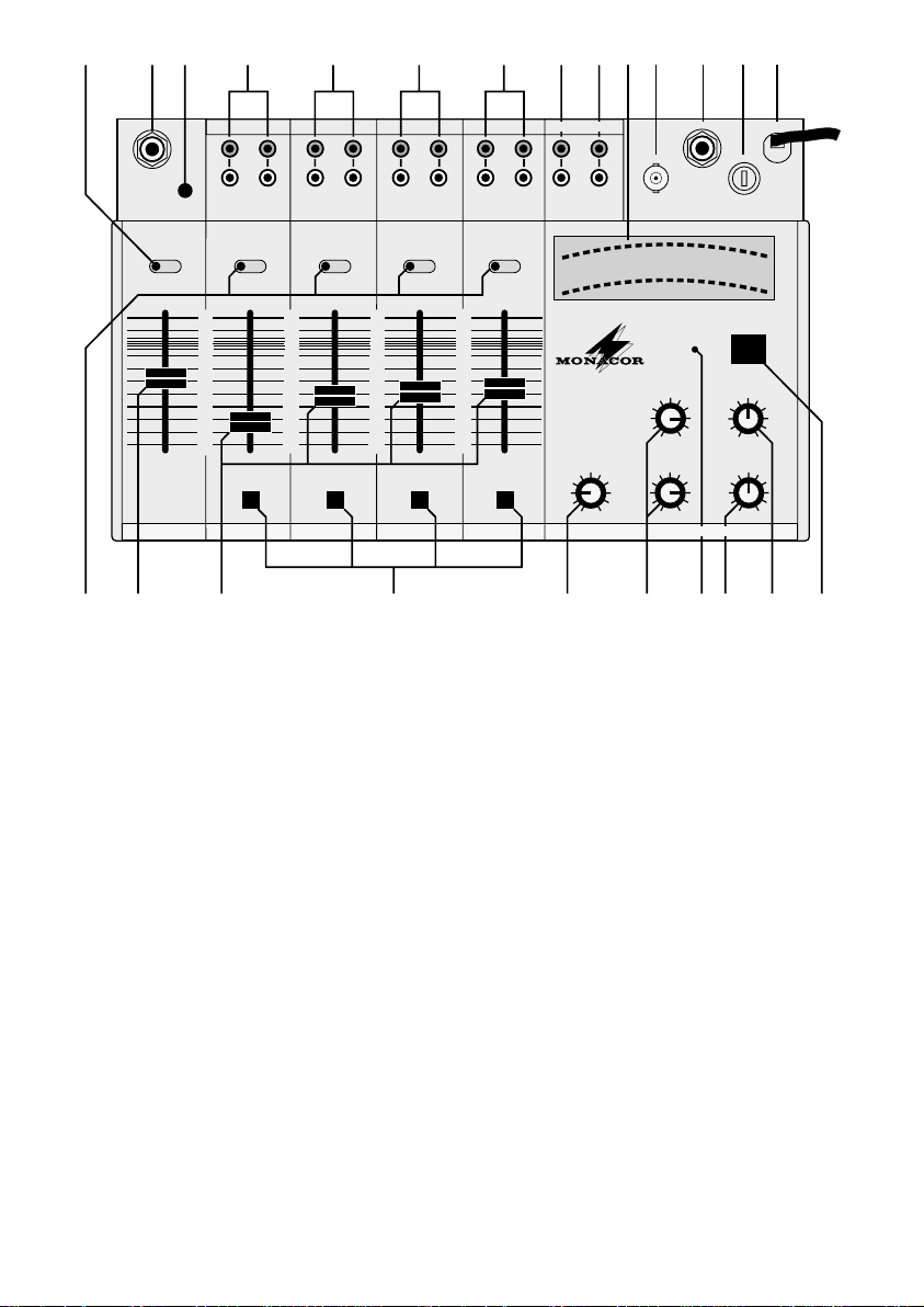
1 Übersicht der Bedienungselemente
und Anschlüsse
1 Talkover-Schalter für Mikrofon-Ansagen. In Posi-
tion ON werden die Pegel der Kanäle 1
12dB abgesenkt.
2 Mikrofoneingang, Mono
3 Anschluß für gemeinsamen Erdungspunkt
4 Eingänge für Kanal 1: Phono und CD
5 Eingänge für Kanal 2: Phono und CD
6 Eingänge für Kanal 3: Tape und Tuner
7 Eingänge für Kanal 4: Tape und Video
8 Ausgang REC für Tonaufnahmen oder Anschluß
eines zweiten Verstärkers (parallelgeschaltet mit
dem Ausgang OUT)
9 Ausgang OUT für den Anschluß eines Verstärkers
10 LED-Pegelanzeige für die Mischpultausgänge
REC (8) und OUT (9)
11 BNC-Anschlußbuchse für eine Pultlampe 12 V/3W
12 Anschluß für Stereo-Kopfhörer ≥8Ω
13 Sicherung
14 Netzkabel für die Stromversorgung 230V~/50 Hz
15 Eingangsumschalter für die Kanäle 1
16 Pegelregler für den Mikrofoneingang
17 Fader (Stereo) für die Kanäle 1
18 Monitor-Wahltasten für den Kopfhörer
19 Lautstärkeregler für den Kopfhörer
20 Klangregler für die Ausgänge REC (8) und OUT(9)
21 Betriebsanzeige
22 Stereo-Summenregler MASTER für die Ausgänge
REC (8) und OUT (9)
23 Balance-Regler für die Ausgänge REC (8) und
OUT (9)
24 Ein-/Ausschalter
-
-
4
schlußleitung vorhanden sind,
2. nach einem Sturz oder ähnlichem der Verdacht
auf einen Defekt besteht,
3. Funktionsstörungen auftreten.
Das Gerät in jedem Fall zur Reparatur in eine Fachwerkstatt geben.
Eine beschädigte Netzanschlußleitung darf nur
•
-
4 um
durch den Hersteller oder eine autorisierte Fachwerkstatt ersetzt werden.
Den Netzstecker nie an der Zuleitung aus der Steck-
•
dose ziehen.
Wird das Gerät zweckentfremdet, falsch bedient
•
oder nicht fachgerecht repariert, kann für eventuelle
Schäden keine Haftung übernommen werden.
Für die Reinigung nur ein trockenes Staubtuch ver-
•
wenden, auf keinen Fall Chemikalien oder Wasser.
3 Inbetriebnahme
1) Zuerst die Eingänge (4-7) mit den Signalquellen
verbinden: Plattenspieler mit Magnetsystem an die
Buchsen PHONO, alle anderen Cinch-Buchsen
sind für Geräte mit Line-Ausgangspegel. Die Eingangsumschalter (15) auf die entsprechende Position stellen. Ein Mikrofon (Mono) kann an die Klinkenbuchse (2) angeschlossen werden.
2) Den Verstärker an die Cinch-Buchsen OUT (9)
4
anschließen.
3) Für eventuelle Tonaufnahmen ein Aufnahmegerät
an die Cinch-Buchsen REC (8) anschließen. Der
Aufnahmepegel ist vom Summenregler MASTER
(22) abhängig. Alternativ dazu kann an die Buchse
REC (8) ein zweiter Verstärker angeschlossen werden.
4) Zuletzt den Netzstecker in die Steckdose (230 V~/
50Hz) stecken.
5) Um starke Einschaltgeräusche zu vermeiden, zuerst den Summenregler MASTER (22) auf Minimum stellen. Dann das Mischpult mit dem Schalter
POWER (24) einschalten und danach den Verstärker.
2 Hinweise für den sicheren Gebrauch
Dieses Gerät entspricht den EU-Richtlinien Nr.
89/ 336/EWG für elektromagnetische Verträglichkeit
und Nr. 73/23/EWG für Niederspannungsgeräte.
Das Gerät wird mit lebensgefährlicher Netzspannung (230 V~) versorgt. Nehmen Sie deshalb niemals selbst Eingriffe im Gerät vor. Durch unsachgemäßes Vorgehen besteht die Gefahr eines
elektrischen Schlages. Außerdem erlischt beim Öff-
nen des Gerätes jeglicher Garantieanspruch.
Beachten Sie für den Betrieb auch unbedingt die folgenden Punkte:
Das Gerät ist nur zur Verwendung in Räumen geeig-
•
net.
Schützen Sie das Gerät vor Feuchtigkeit und Hitze.
•
Das Gerät nicht in Betrieb nehmen und sofort den
•
Netzstecker ziehen, wenn:
1. sichtbare Schäden am Gerät oder an der Netzan-
4
4 Bedienung
1) Den Talkover-Schalter (1) in Position OFF stellen.
(In Position ON werden die Pegel der Kanäle 1-4
um 12dB abgesenkt.)
2) Mit den Fadern (17) den Pegel der Signalquellen
einstellen.
3) Für die Ausgänge REC (8) und OUT (9) mit dem
Summenregler MASTER (22) den Ausgangspegel
nach der Pegelanzeige (10) einstellen und die
Balance mit dem Regler (23).
4) Den Klang mit den Reglern (20) einstellen. Die
Regler beeinflussen die beiden Ausgänge REC (8)
und OUT (9).
5) Für eine optimale Pultbeleuchtung kann eine
Schwanenhals-Pultlampe 12 V/ 3W (zum Beispiel:
MONACOR GNL-200, nicht im Lieferumfang) in
die Buchse LAMP (11) gesteckt werden.
Page 5

5 Vorhör-Kontrolle (Monitor)
Die Kanäle 1-4 können einzeln über einen Kopfhörer
abgehört werden. Wenn der entsprechende Fader auf
Minimum steht, kann damit der günstigste Zeitpunkt
zum Einblenden einer Signalquelle gewählt werden.
1) Dazu einen Kopfhörer (≥ 8 Ω) an die Buchse
PHONES (12) anschließen.
2) Mit den Tasten (18) den Kanal, der abgehört werden soll, anwählen.
3) Mit dem Regler MON LEVEL (19) die KopfhörerLautstärke einstellen.
ACHTUNG: Stellen Sie die Kopfhörerlautstärke nie
sehr hoch ein. Hohe Lautstärken können auf Dauer
das Gehör schädigen! Das menschliche Ohr
gewöhnt sich an große Lautstärken und empfindet
sie nach einiger Zeit nicht mehr so hoch. Darum
eine hohe Lautstärke nach der Gewöhnung nicht
weiter erhöhen.
6 Mikrofondurchsage
Für das Mikrofon die Lautstärke mit dem Fader (16)
einstellen. Zur besseren Verständlichkeit einer Mikrofondurchsage können mit dem Talkover-Schalter (1)
die Pegel der Kanäle 1
den.
-
4 um 12 dB abgesenkt wer-
7 Technische Daten
Eingänge
MIC: . . . . . . . . . . . . . . . 1mV/600 Ω
PHONO mag.: . . . . . . . . 3 mV/50kΩ
CD/TUNER/TAPE/VIDEO:
Ausgänge
OUT: . . . . . . . . . . . . . . . 0,775 V/600Ω
REC: . . . . . . . . . . . . . . . 0,775 V /600Ω
Frequenzbereich: . . . . . . . 20
Klirrfaktor: . . . . . . . . . . . . . 0,1%
Störabstand: . . . . . . . . . . . 65dB
Bass/Treble: . . . . . . . . . . . 100Hz/10kHz, ±10 dB
Kopfhörerausgang: . . . . . . ≥ 8 Ω, Stereo
Talkover: . . . . . . . . . . . . . .
Stromversorgung: . . . . . . . 230 V~/50Hz/12VA
Abmessungen (BxHx T): . 338 x 11 x 215mm
Gewicht: . . . . . . . . . . . . . . 2,4kg
Laut Angaben des Herstellers.
Änderungen vorbehalten.
150mV/100 kΩ
-
20000Hz
-
12dB
Frontplatte 338 x 156mm
D
A
CH
5
Page 6

GB6Please unfold page 3. Then you can always see the
operating elements and connections described.
1 Operating Elements and Connections
1 Talkover switch for microphone announcements. In
ON position the levels of the channels 1-4 will be
attenuated by 12dB.
2 Microphone input, mono
3 Connection for common grounding point
4 Inputs for channel 1: Phono and CD
5 Inputs for channel 2: Phono and CD
6 Inputs for channel 3: Tape and tuner
7 Inputs for channel 4: Tape and video
8 Output REC for recordings or connection of a
second amplifier [connected in parallel with OUT
(=output)]
9 OUT (= output) for the connection of an amplifier
10 LED VU meter for the mixer outputs REC (8) and
OUT (9)
11 BNC jack for a console lampe 12 V/3W
12 Connection for stereo headphones ≥ 8 Ω
13 Fuse
14 Power cable 230 V~/50Hz
-
15 Input selector switches for the channels 1
16 Level control for the microphone input
17 Faders (stereo) for the channels 1
18 Monitor selector buttons for the headphones
19 Volume control for the headphones
20 Equalizer for the outputs REC (8) and OUT (9)
21 Power LED
22 Stereo MASTER control for the outputs REC (8)
and OUT (9)
23 Balance control for the outputs REC (8) and OUT
(9)
24 On/Off switch
-
4
4
2 Safety Notes
The appliance corresponds to the EC Directives No.
89/336/EWG for electromagnetic compatibility and
No. 73/23/EWG for low voltage appliances.
This unit uses lethally high voltage (230V~). To prevent a shock hazard do not open the cabinet. Leave
servicing to authorized skilled personnel only. Also
any guarantee claim expires if the unit has been
opened.
For the operation also watch in any case the following
items:
The unit is only suitable for indoor use.
•
Avoid excessively warm locations for the unit or high
•
humidity.
Do not set the unit into operation and immediately
•
take the mains plug out of the mains socket if:
1. damage at the unit or mains cable can be seen.
2. a defect might have occurred after a drop or simi-
lar accident.
3. there are malfunctions.
The unit must in any case be repaired by authorized
skilled personnel.
A damaged mains cable must only be repaired by
•
the manufacturer or authorized skilled personnel.
Never pull the mains plug out of the mains socket by
•
means of the mains cable.
If the unit is used for purposes other than originally
•
intended, if it is operated in the wrong way or not
repaired by authorized skilled personnel, there is no
liability for possible damage.
For the cleaning only use a dry cloth for dust remov-
•
ing, by no means chemicals or water.
Important for U.K. Customers!
•
The wires in this mains lead are coloured in accordance with the following code:
blue = neutral
brown = live
As the colours of the wires in the mains lead of this
appliance may not correspond with the coloured
markings identifying the terminals in your plug, proceed as follows:
1. The wire which is coloured blue must be connected to the terminal in the plug which is marked with
the letter N or coloured black.
2. The wire which is coloured brown must be
connected to the terminal which is marked with the
letter L or coloured red.
3 Setting into Operation
1) At first connect the inputs (4-7) with the signal
sources: Turntable with magnet system to the
PHONO jacks, all other cinch jacks are provided
for units with line output level. Set the input selector
switch (15) to the corresponding position. A microphone (mono) can be connected to the
(2).
2) Connect the amplifier to the cinch jacks OUT (9).
3) For recordings connect a recording unit to the cinch
jacks REC (8). The recording level depends on the
MASTER control (22). Alternatively to this a second
amplifier can be connected to the REC jack (8).
4) Finally connect the mains plug to the socket
(230V~/50 Hz).
5) In order to avoid a strong inrush bump, at first set
the MASTER control (22) to minimum. Then switch
on the mixer with the POWER switch (24) and afterwards the amplifier.
1
/4”jacks
4 Operation
1) Set the talkover switch to OFF position. (In ON
position the levels of the channels 1-4 will be
attenuated by 12dB).
2) Adjust the level of the signal sources with the
faders (17).
3) For the outputs REC (8) and OUT (9) adjust the
output level with the MASTER control (22) according to the VU meter (10) and adjust the balance
with the control (23).
Page 7

4) Adjust the tone with the controls (20). The controls
influence both outputs REC (8) and OUT (9).
5) For an optimum console lighting a gooseneck console lamp 12 V/3 W (e.g. MONACOR GNL-200,
not included) can be connected to the LAMP jack
(11).
5 Pre-Fader Listening (Monitor)
The channels 1-4 can individually be monitored via
headphones. If the corresponding fader is set to minimum, by this the most favourable point of time for
fading in a signal source can be chosen.
1) For this connect headphones (≥ 8 Ω) to the
PHONES jack (12).
2) Choose the channel to be monitored with the buttons (18).
3) Adjust the headphones volume with the control
MON LEVEL (19).
Attention! Never adjust the headphones volume
too high. Permanent high volumes may damage a
person's hearing. The hearing gets accustomed to
high volumes which after some time do not seem to
be so high. Therefore do not further increase a high
volume after getting used to it.
6 Microphone Announcement
For the microphone adjust the volume with the fader
(16). For better intelligibility of a microphone announcement the music level of the channels 1-4 will
be attenuated by 12dB with the talkover switch (1).
7 Specifications
Inputs
MIC: . . . . . . . . . . . . . . . 1mV/600 Ω
PHONO mag.: . . . . . . . . 3 mV/50kΩ
CD/TUNER/TAPE/VIDEO:
Outputs
OUT: . . . . . . . . . . . . . . . 0.775 V/600Ω
REC . . . . . . . . . . . . . . . 0.775V/600 Ω
Frequency range: . . . . . . . 20
THD: . . . . . . . . . . . . . . . . . 0.1%
S/N ratio: . . . . . . . . . . . . . . 65 dB
Bass/treble . . . . . . . . . . . . 100Hz/10kHz, ±10 dB
Headphones output . . . . . . ≥8Ω, stereo
Talkover: . . . . . . . . . . . . . .
Power supply: . . . . . . . . . . 230 V~ /50Hz/12VA
Dimensions (WxHxD): . . . . 338 x 11 x 215mm
Weight: . . . . . . . . . . . . . . . 2.4 kg
According to the manufacturer.
Subject to technical change.
150mV/100 kΩ
-
20000Hz
-
12dB
Front panel
338 x 156mm
GB
7
Page 8

Ouvrez le livret page 3 de manière à visualiser les
F
éléments et branchements.
B
CH
1 Eléments et branchements
1 Interrupteur Talkover pour les annonces micro. En
position ON, les niveaux des canaux 1-4 sont
diminués de 12dB.
2 Entrée micro mono
3 Connexion pour le point commun de mise à la terre
4 Entrées pour le canal 1: Phono et CD
5 Entrées pour le canal 2: Phono et CD
6 Entrées pour le canal 3: Tape et Tuner
7 Entrées pour le canal 4: Tape et Video
8 Sortie REC pour effectuer un enregistrement ou
pour brancher un second amplificateur (branché
en parallèle à la sortie OUT)
9 Sortie OUT: pour brancher un amplificateur
10 VU-mètre d’affichage pour les sorties REC
(enregistrement) (8) et OUT (9) d’une table de
mixage
11 Prise BNC pour brancher une lampe col de cygne,
12V/3 W
12 Prise pour un casque ≥ 8 Ω
13 Fusible
14 Câble secteur 230 V~ /50Hz
15 Interrupteurs d’entrée pour les canaux 1
16 Potentiomètre linéaire pour l’entrée micro
17 Potentiomètres linéaires pour les canaux 1
18 Touches Monitor pour le casque
19 Réglage du volume du casque
20 Réglages du son, sorties REC (8) et OUT (9)
21 Diode témoin de fonctionnement
22 Réglage de la somme stéréo MASTER pour les
sorties REC (8) et OUT (9)
23 Réglage de balance pour les sorties REC (8) et
OUT (9)
24 Interrupteur général MARCHE/ARRET
2 Conseils d’utilisation
Cet appareil répond aux normes figurant dans la directive européennne 89/336/EWG relative à la compatibilité électro-magnétique et dans la directive
73/ 23/ EWG porttant sur les appareils à basse tension.
Cette table de mixage est alimentée par une tension
en 230 V~. Ne touchez jamais l’intérieur de l’appareil car, en cas de mauvaise manipulation, vous
pourriez subir une décharge électrique mortelle.
Faites plutôt appel à un spécialiste. De plus, si l’appareil est ouvert par une personne non habilitée, l’u-
tilisateur perd tout droit de garantie.
Pour une utilisation optimale et sûre de votre appareil,
respectez scrupuleusement les points suivants:
Cet appareil n’est conçu que pour une utilisation en
•
intérieur.
Protégez l’appareil de l’humidité et de la chaleur.
•
Ne faites pas fonctionner l’appareil et débranchez-le
•
immédiatement dans les cas suivants:
1. l’appareil ou le cordon secteur présente des dommages.
2. après une chute, ou un autre accident l’appareil
présente un défaut.
3. des disfonctionnements apparaissent.
Dans tous les cas, les dommages doivent être
réparés par un technicien spécialisé.
Tout cordon secteur endommagé ne doit être rem-
•
placé que par le constructeur ou un technicien habilité.
Ne retirez jamais le cordon secteur de la prise en
•
tirant dessus.
Si l’appareil est utilisé dans un but autre que celui
•
pour lequel il a été conçu, s’il n’est pas réparé par
une personne habilitée, ou utilisé incorrectement
l’utilisateur perd tout droit de garantie.
Pour nettoyer l’appareil, utilisez un chiffon sec, en
•
aucun cas de produits chimiques ou d’eau.
3 Mise en service
1) Reliez les entrées (4-7) aux sources: une platinedisques avec cellule magnétique aux prises
PHONO, tout autre appareil à niveau de sortie
LINE aux prises RCA. Mettez le sélecteur d’entrée
-
4
-
4
(15) sur la position voulue. Vous pouvez relier un
micro mono aux prises jack (2).
2) Reliez maintenant l’ampli aux prises RCA OUT (9).
3) Si vous souhaitez effectuer des enregistrements,
reliez l’appareil aux prises RCA REC (8). Le
niveau d’enregistrement dépend du réglage de la
somme MASTER (22). Comme alternative vous
pouvez également brancher un second ampli aux
prises REC (8).
4) Reliez maintenant la table de mixage au secteur
(230V~/50 Hz)
5) Pour éviter tout bruit fort, mettez, en premier lieu, le
réglage MASTER (22) sur le minimum, allumez la
table avec l’interrupteur MARCHE/ARRET (24)
puis l’ampli.
4 Utilisation
1) Positionnez le commutateur Talkover (1) sur la
position OFF (en position ON, les niveaux des can-
-
4 sont diminués de 12dB).
aux 1
2) Utilisez les potentiomètres (17) pour régler le
niveau des sources.
3) Pour les sorties REC (8) et OUT (9), réglez le
niveau de sortie avec le réglage (22) en vous
référant au VU-mètre (10) puis la balance avec le
réglage (23).
4) Réglez maintenant le son (20) pour les deux sorties REC (8) et OUT (9).
5) Vous pouvez brancher une lampe col de cygne
12V/3W (par exemple MONACOR GNL-200, non
livrée) à la prise LAMP (11).
8
Page 9

5 Contrôle préécoute (monitor)
Il est possible d’effectuer une préécoute des canaux
1-4 séparément. Si le potentiomètre correspondant
est sur le minimum, on peut sélectionner le moment
exact pour effectuer un fondu-enchaîné dans le signal
source.
1) Pour ce faire, reliez un casque ≥ 8 Ω à la prise
PHONES (12).
2) Sélectionnez le canal où vous voulez effectuer la
préécoute avec les touches (18).
3) Réglez le volume avec le réglage MON LEVEL
(19).
Attension! Ne réglez pas le volume du casque trop
fort. Des volumes trop élevés peuvent, à la longue,
causer des troubles de l'audition. L'oreille humaine
s'habitue à des volumes élevés et avec le temps,
ne les perçoit pas de la même manière. C'est pourquoi nous conseillons de ne plus modifier le volume
d'écoute une fois que votre oreille s'y est habituée.
6 Annonce micro
Réglez le volume du micro avec le potentiomètre (16).
Pour une meilleure compréhension de l’annonce
micro, vous pouvez diminuer les niveaux des canaux
-
4 de 12dB avec l’interrupteur Talkover (1).
1
7 Caractéristiques techniques
Entrées
MIC . . . . . . . . . . . . . . . . 1 mV/600Ω
PHONO mag . . . . . . . . . 3 mV/50kΩ
CD/TUNER/TAPE/VIDEO
Sorties
OUT . . . . . . . . . . . . . . . 0,775V/600 Ω
REC . . . . . . . . . . . . . . . 0,775V/600 Ω
Bande passante . . . . . . . . 20
Taux de distorsion . . . . . . . 0,1 %
Rapport signal/bruit . . . . . 65 dB
Bass/treble . . . . . . . . . . . . 100 Hz/10 kHz,
Sortie casque . . . . . . . . . . ≥8Ω, stéréo
Talkover . . . . . . . . . . . . . . .
Alimentation . . . . . . . . . . . 230 V~/50Hz/12VA
Dimensions (LxHxP) . . . . 338 x 11 x 215mm
Poids . . . . . . . . . . . . . . . . . 2,4 kg
D’après les données du constructeur.
Tout droit de modification réservé.
. 150 mV/100kΩ
-
20000Hz
±10 dB
-
12dB
Face avant
338x156mm
F
B
CH
9
Page 10

Vi preghiamo di aprire completamente la pagina 3.
I
Così vedrete sempre gli elementi di comando e i
collegamenti descritti.
1 Elementi di comando e collegamenti
1 Commutatore talkover per annunci col microfono.
In posizione ON, i livelli dei canali 1
abbassati di 12dB
2 Ingresso microfono, mono
3 Contatto per massa comune
4 Ingressi per canale 1: Phono e CD
5 Ingressi per canale 2: Phono e CD
6 Ingressi per canale 3: Tape e Tuner
7 Ingressi per canale 4: Tape e Video
8 Uscita REC per registrazioni o per il collegamento
di un secondo amplificatore (collegato in parallelo
con l’uscita OUT)
9 Uscita OUT per il collegamento di un amplificatore
10 Indicazione livello a LED per le uscite mixer REC
(8) e OUT (9)
11 Presa BNC per una lampada per il mixer, 12V/3 W
12 Collegamento di una cuffia stereo ≥ 8 Ω
13 Fusibile
14 Cavo rete per alimentazione 230 V~/50Hz
15 Commutatori d’ingresso per i canali 1
16 Regolatore livello per ingresso micro
17 Fader (stereo) per i canali 1
18 Tasti selettori monitor per cuffia
19 Regolatore volume cuffia
20 Regolatori suono per le uscite REC (8) e OUT (9)
21 Spia funzionamento
22 Regolatore somme stereo MASTER per le uscite
REC (8) e OUT (9)
23 Regolatore balance per le uscite REC (8) e OUT
(9)
24 Interruttore ON/OFF
-
-
4
2 Avviso di sicurezza
Questo apparecchio corrisponde alle norme CE
89/ 336/ CEE sulla compatibilità elettromagnetica ed
alle norme 73/ 23 /CEE per apparecchi a bassa tensione.
Questo apparecchio funziona con tensione di rete di
230V~. Non intervenire mai al suo interno; la manipolazione scorretta può provocare delle scariche
pericolose. Se l’apparecchio viene aperto, ogni
diritto di garanzia viene a decadere.
Durante l’uso si devono osservare assolutamente i
seguenti punti:
L’apparecchio è previsto solo per l’uso all’interno di
•
locali.
Proteggere l’apparecchio dall’umidità e dal calore.
•
Non mettere in funzione l’apparecchio e staccare
•
subito la spina rete se:
1. l’apparecchio o il cavo rete presentano dei danni
visibili;
10
4
-
4 sono
2. dopo una caduta o dopo eventi simili sussiste il
sospetto di un difetto;
3. l’apparecchio non funziona correttamente.
Per la riparazione rivolgersi sempre ad una officina
competente.
Il cavo rete, se danneggiato, può essere sostituito
•
solo dal costruttore o da un laboratorio autorizzato.
Staccare il cavo rete afferrando la spina, senza tir-
•
are il cavo.
Nel caso di uso improprio, di impiego scorretto o di
•
riparazione non a regola d’arte non si assume nessuna responsabilità per eventuali danni.
Per la pulizia usare solo un panno asciutto; non
•
impiegare in nessun caso prodotti chimici o acqua.
3 Messa in funzione
1) Per prima cosa collegare gli ingressi (4-7) con le
sorgenti: giradischi con sistema magnetico alla
prese PHONO, le altre prese cinch sono per strumenti con livello di uscita LINE. Regolare in tal
senso i commutatori d’ingresso (15). La presa jack
(2) serve per un microfono (mono).
2) Collegare l’amplificatore con le prese cinch OUT
(9).
3) Nel caso di registrazioni, collegare il registratore
con le prese cinch REC (8). Il livello di registrazione
dipende dal regolatore MASTER (22). In alternativa
si può collegare un secondo amplificatore alla
presa REC (8).
4) Alla fine inserire la spina del cavo nella presa di
rete (230V~/50 Hz).
5) Per evitare forti rumori di commutazione, conviene
mettere inizialmente il regolatore MASTER (22) sul
minimo. Quindi accendere il mixer con l’interruttore
POWER (24) e quindi l’amplificatore.
4 Funzionamento
1) Portare il commutatore talkover (1) in posizione
OFF (in posizione ON, i livelli dei canali 1-4 sono
abbassati di 12dB).
2) Regolare il livelli delle sorgenti usando i fader (17).
3) Con il regolatore MASTER (22) regolare il livello
d’uscita di REC (8) e OUT (9) secondo le indicazioni (10). Impostare il bilanciamento con il regolatore (23).
4) Impostare il suono con i regolatori (20) che agiscono sulle uscite REC (8) e OUT (9).
5) Per illuminare il mixer si può inserire una lampada
a collo di cigno 12V/3 W (p. es. MONACOR GNL200, non compresa) nella presa LAMP (11).
Page 11

5 Controllo preascolto (monitor)
Esiste la possibilità di preascolto singolo dei canali
-
4 mediante una cuffia. Se il relativo fader è sul
1
minimo, si può scegliere così il momento adatto per
inserire la sorgente.
1) Collegare una cuffia (≥8Ω) con la presa PHONES
(12).
2) Con i tasti (18) selezionare il canale desiderato.
3) Regolare il volume della cuffia con il regolatore
MON LEVEL (19).
Attenzione! Mai tenere molto alto il volume nelle
cuffie. A lungo andare, il volume eccessivo può
procurare danni all'udito! L'orecchio si abitua agli
alti volumi e dopo un certo tempo non se ne rende
più conto. Non aumentare il volume successivamente.
6 Annuncio col microfono
Regolare il volume del microfono con il fader (16). Per
rendere più comprensibile l’annuncio, con il commutatore talkover (1) si possono abbassare i livelli dei
-
canali 1
4 di 12dB.
7 Dati tecnici
Ingressi
MIC: . . . . . . . . . . . . . . . 1mV/600 Ω
PHONO mag.: . . . . . . . . 3 mV/50kΩ
CD/TUNER/TAPE/VIDEO:
Uscite
OUT: . . . . . . . . . . . . . . . 0,775 V/600Ω
REC: . . . . . . . . . . . . . . . 0,775 V/600Ω
Banda passante: . . . . . . . . 20
Fattore di distorsione: . . . . 0,1 %
Rapporto S/R: . . . . . . . . . . 65dB
Bass/Treble: . . . . . . . . . . . 100 Hz/10 kHz, ±10dB
Uscita cuffia: . . . . . . . . . . . ≥ 8 Ω, stereo
Talkover: . . . . . . . . . . . . . .
Alimentazione: . . . . . . . . . 230V~/50Hz/12VA
Dimensioni (LxHxP): . . . . 338 x 11 x 215mm
Peso: . . . . . . . . . . . . . . . . . 2,4kg
Dati forniti dal costruttore.
Con riserva di modifiche tecniche.
150mV/100 kΩ
-
20000Hz
-
12dB
pannello frontale
338x156mm
I
11
Page 12

Vouw bladzijde 3 helemaal open, zodat u een over-
NL
zicht hebt van de bedieningselementen en de
B
aansluitingen.
1 Overzicht van de functies, regelaars
en aansluitingen
1 TALKOVER-schakelaar voor aankondigingen via
microfoon. In de positie TALK worden de geluidsniveaus van kanalen 1 tot 4 met 12 dB gedempt.
2 Mono-microfooningang
3 Aansluiting voor een gemeenschappelijk aardings-
punt
4 Ingangen voor kanaal 1: PHONO en CD
5 Ingangen voor kanaal 2: PHONO en CD
6 Ingangen voor kanaal 3: TAPE en TUNER
7 Ingangen voor kanaal 4: TAPE en VIDEO
8 Opname-uitgang REC: Deze uitgang kan ook voor
de aansluiting van een tweede versterker dienen
(parallelgeschakeld met de OUT-uitgang).
9 OUT-uitgang voor de aansluiting van een verster-
ker
10 LED-VU-meter van de mengpaneeluitgangen REC
(8) en OUT (9)
11 BNC-connector voor mengpaneelverlichting
(12V/3 W)
12 Aansluiting voor een stereo-hoofdtelefoon ≥ 8 Ω
13 Zekering
14 Netsnoer voor aansluiting op het elektriciteitsnet
(230V~/50 Hz)
15 Ingangskeuzeschakelaar voor de kanalen 1 tot 4.
16 Volumeregelaar voor de microfooningang
17 Stereo-schuifregelaar voor kanalen 1 tot 4
18 Keuzetoetsen voor de voorafluistering via de
hoofdtelefoon
19 Volumeregelaar voor de hoofdtelefoon
20 Equalizer voor de uitgangen REC (8) en OUT (9)
21 POWER-LED
22 Stereo-masterregelaar voor de uitgangen REC (8)
en OUT (9)
23 Balansregelaar voor de uitgangen (8) en (9)
24 POWER-schakelaar
Vermijd uitzonderlijk warme plaatsen.
•
Bescherm het toestel tegen, trillingen, rechtstreeks
•
zonlicht, hoge vochtigheid en stof.
Schakel het toestel niet in en trek onmiddellijk de
•
stekker uit het stopcontact wanneer:
1. het netsnoer zichtbaar beschadigd is.
2. er een defect zou kunnen optreden nadat het toestel bijvoorbeeld gevallen is.
3. het toestel slecht functioneert.
Het apparaat moet in elk geval hersteld worden
door een gekwalificeerd vakman.
Een defect netsnoer mag enkel door de fabrikant of
•
door een gekwalificeerd persoon hersteld worden.
Trek de stekker nooit met het snoer uit het stop-
•
contact.
In geval van ongeoorloofd of verkeerd gebruik of
•
van herstelling door een niet-gekwalificeerd persoon vervalt de garantie bij eventuele schade.
Verwijder het stof met een droog doek. Gebruik
•
zeker geen chemicaliën of water.
3 Ingebruikname
1) Verbind eerst de ingangen (4-7) met de signaalbronnen: draaitafel met MD-element aan de
PHONO-jack; apparatuur met lijn-uitgangsniveau
aan alle andere cinch-ingangen. Plaats de keuzeschakelaar (15) in de juiste stand. Aan de jack (2)
op het frontpaneel kan een mono-microfoon aangesloten worden.
2) Verbind de versterker met de cinch-connectoren
OUT (9).
3) Verbind een opnametoestel met de cinch-connectoren REC (8) voor eventuele geluidsopnamen.
Het geluidsvolume van de opname wordt door de
MASTER-regelaar (22) bepaald. Desgewenst kunt
u een tweede versterker aansluiten op de RECingang (8).
4) Verbind tenslotte het netsnoer met het elektriciteitsnet (230V~/50 Hz).
5) Zet de MASTER-regelaar (22) eerst in de minimum-stand om luide schakelploppen te vermijden.
Zet dan het mengpaneel met de POWER-schakelaar (24) aan en daarna de versterker.
2 Veiligheidsvoorschriften
Dit apparaat voldoet aan de EC richtlijnen No.
89/336/EWG voor electromagnetische compatibiliteit
en No. 73/23/EWG voor laagspannings apparaten.
De netspanning waarmee dit toestel gevoed wordt
is levensgevaarlijk! Open het toestel niet, want door
onzorgvuldige ingrepen loopt u het risico van een
elektrische schok. Onderhoud dient te gebeuren
door een gekwalificeerd vakman. Bovendien vervalt
elke garantie bij het eigenhandig openen van het
toestel.
Let bij ingebruikname eveneens op het volgende:
Het toestel is enkel geschikt voor gebruik binnens-
•
huis.
12
4 Werking
1) Zet de TALKOVER-schakelaar (1) in de OFFstand. (In de TALK-stand wordt het geluidsvolume
van de kanalen 1 tot 4 met 12dB gedempt.)
2) Regel met de schuifregelaars (17) het geluidsvolume van de signaalbronnen.
3) Regel met de MASTER-regelaar (22) het volume
aan de uitgangen REC (8) en OUT (9) naar de versterker. Het volume van dit uitgangssignaal kan op
de LED-meter (10) afgelezen worden. Stel de balans in met de regelaar (23).
4) Regel de klank met de equalizer (20). Deze toonregelaars beïnvloeden het signaal van de uitgangen
REC (8) en OUT (9).
Page 13

5) Gebruik voor een optimale mengpaneelverlichting
een zwanehalslamp van 12V/3 W, bv. de GNL-200
van MONACOR (niet in de levering).
5 Voorafluistering (Monitor)
De kanalen 1 tot 4 en de mengpaneeluitgang kunnen
apart via een hoofdtelefoon afgeluisterd worden.
Wanneer de desbetreffende schuifregelaar in de minimum-stand staat, kan zo het ideale moment worden
gekozen om een signaalbron langzaam naar de voorgrond te mixen.
1) Sluit daarvoor een hoofdtelefoon (≥ 8 Ω) op de
PHONES-connector (12) aan.
2) Selecteer met de toetsen (18) het kanaal of de uitgang (MASTER).
3) Regel met de VOLUME-knop (19) het geluidsvolume van de hoofdtelefoon af.
Attention! Zet nooit het hoofdtelefoon volume op
een te hoog niveau. Het gehoor raakt gewend aan
deze hoge volumes waardoor het geluid na verloop
van tijd niet meer zo hard lijkt. Verhoog hierna echter nooit het volume. Langdurige blootstelling aan
te luide volumes kan het gehoor aantasten.
6 Aankondiging via de microfoon
Regel het geluidsvolume van het microfoonkanaal met
behulp van de schuifregelaar (16) af. Om de aankondiging via de microfoon beter verstaanbaar te maken,
kan het uitgangsvolume van de kanalen 1 tot 4 door
middel van de TALKOVER-schakelaar (1) met 12dB
worden gedempt.
7 Technische gegevens
Ingangen
MIC . . . . . . . . . . . . . . . . 1 mV/600Ω
PHONO (magn. elem.) . 3 mV/50kΩ
CD/TUNER/TAPE/VIDEO
Uitgangen
OUT . . . . . . . . . . . . . . . 0,775V/600 Ω
REC . . . . . . . . . . . . . . . 0,775V/600 Ω
Frequentiebereik . . . . . . . . 20
THD . . . . . . . . . . . . . . . . . . 0,1%
Signaal/Ruis-verhouding . . 65dB
Equalizer . . . . . . . . . . . . . . 100 Hz/10 kHz, ±10dB
Hoofdtelefoonuitgang . . . . ≥ 8 Ω, stereo
Talkover . . . . . . . . . . . . . . .
Voedingsspanning . . . . . . . 230 V~/50Hz/12VA
Afmetingen (BxHxD) . . . . . 338 x 11 x 215 mm
Gewicht . . . . . . . . . . . . . . . 2,4 kg
Opgemaakt volgens de gegevens van de fabrikant.
Deze behoudt zich het recht voor de technische gegevens te veranderen.
. 150 mV/100kΩ
-
20000Hz
-
12dB
NL
B
13
Page 14

Dirigirse a la página 3 para ver los elementos ope-
E141) Conectar los auriculares (≥ 8 Ω) en la toma
rativos y las conexiones descritas.
1 Elementos Operativos y Conexiones
1 Interruptor Talkover para micrófono. En posición
ON los niveles de los canales 1-4 se atenuan
12dB.
2 Entrada micrófono, mono.
3 Conexión para masa común
4 Entradas para canal 1: Phono y CD
5 Entradas para canal 2: Phono y CD
6 Entradas para canal 3: Cassette y Sintonizador
7 Entradas para canal 4: Cassette y video
8 Salida REC para grabaciones o conexión de otro
amplificador (conexión en paralelo con OUT
(= salida)
9 OUT (= salida) para la conexión de un amplificador
10 VU-meters a LED’s para las salidas del mezclador
REC (8) y OUT (9).
11 Conexión BNC para lámpara 12 V/3W.
12 Conexión para auriculares estéreo ≥ 8 Ω.
13 Fusible
14 Alimentación 230 V~/50 Hz
-
15 Selectores de entrada para canales 1
16 Control de nivel para la entrada de micrófono
17 Potenciómetros (estéreo) para los canales 1
18 Botones selectores de monitor para los auriculares
19 Control de volumen para auriculares
20 Ecualizador para las salidas REC (8) y OUT (9)
21 LED de alimentación
22 Control de MASTER estéreo para las salidas REC
(8) y OUT (9)
23 Control de balance para las salidas REC (8) y
OUT (9)
24 Interruptor Encendido/Apagado.
4
-
2 Notas de Uso
Este dispositivo corresponde a las indicaciones de la
C.E.E. n° 89 /336 /EWG para compatibilidad electromagnética y n° 73/23/EWG para dispositivos de baja
tensión.
Este equipo usa alto voltaje (230 V~). Para evitar
accidentes no abrir la tapa de la caja. Dejar el servicio técnico sólo a personal autorizado. Cualquier
garantía del equipo se anula al abrir el equipo.
Para su funcionamiento tener en cuenta los siguientes
puntos:
Este equipo sólo es adecuado para funcionar en
•
interiores.
Proteger el equipo de la humedad y el calor.
•
Desconectar el equipo y el cable de conexión si se
•
observa que:
1. existen daños en el equipo o en el cable de ali-
mentación.
2. puede haberse estropeado después de caerse o
ser golpeado.
3. no funciona correctamente.
El equipo sólo puede repararse por personal cualificado.
Para su limpieza usar un trapo seco, no utilizar
•
nunca agua ni productos químicos.
El cable de alimentación sólo puede cambiarse por
•
el fabricante o por personal autorizado.
Nunca quitar la toma de tensión del zócalo tirando
•
del cable.
Si el equipo se usa para propuestas diferentes de
•
las que están destinadas, si no se usa correctamente o se repara por personal no autorizado, no
existe la responsabilidad en caso de avería.
3 Puesta en Funcionamiento
1) En primer lugar, conectar las entradas (4-7) del
Mezclador Estereo de Audio con las fuentes de
sonido: conexiones de PHONO para platos con
sistema magnético, todas las otras conexiones
para equipos con nivel de salida LINE. Poner los
conmutadores de entrada (15) en la posición correspondiente. Puede conectarse un micrófono mono
con el jack 6,3mm (2).
2) Conectar el amplificador con las conexiones
OUT(9).
3) Para grabaciones conectar el equipo de grabación
a las conexiones REC (8). El nivel de grabación
4
depende del control MASTER (22). Como alternativa, puede conectarse a la salida de grabación, un
segundo amplificador (8).
4) Finalmente conectar la toma a 230 V~/50Hz.
5) Para evitar ruidos de conexión, primero poner el
control de MASTER (22) al mínimo. Conectar el
mezclador con el interruptor POWER (24) y luego
el amplificador.
4 Funcionamiento
1) Poner el interruptor talkover del Mezclador Estereo
de Audio en posición OFF. (En posición ON los
niveles de los canales 1
2) Ajustar el nivel de las fuentes con los potenciómetros (17).
3) Para las salidas REC (8) y OUT (9) ajustar el nivel
de salida con el control MASTER (22) de acuerdo
con los VU-meters (10) y ajustar el balance con el
control (23).
4) Ajustar el tono con los controles (20). Los controles
afectan a todas las salidas REC (8) y OUT (9).
5) Para una visualización óptima de la consola puede
conectarse una lámpara 12V/3 W en la toma
LAMP (11). (Por ejemplo MONACOR GNL-200, no
incluida.)
-
4 se atenúan 12dB.)
5 Monitorización Pre-Fader
-
Los canales 1
mente con los auriculares. Si el potenciómetro correspondiente está al mínimo, puede buscarse el punto de
arranque más adecuado para cada canal.
4 pueden monitorizarse individual-
Page 15

PHONES (12).
2) Buscar el canal a monitorizar con los botones (18).
3) Ajustar el volumen de los auriculares con el control
MON LEVEL (19).
Atención! Nunca ajustar los auriculares a volumen
máximo. Elevados volúmenes permanentes pueden dañar el oído de las personas. El oído puede
acostumarse a los altos volúmenes y no darse
cuenta de lo elevado que se encuentra. No incrementar los volúmenes elevados después de usarlo.
6 Uso del Micrófono
Para el ajuste del micrófono ajustar el volumen con el
potenciómetro (16). Para hacer mas entendedor el
habla por el micrófono, el nivel musical de los canales
-
4, puede atenuarse 12dB con el interruptor de talk-
1
over (1).
7 Características
Entradas
MIC: . . . . . . . . . . . . . . . 1mV/600 Ω
PHONO mag.: . . . . . . . . 3 mV/50kΩ
CD/TUNER/TAPE/VIDEO:
Salidas
OUT: . . . . . . . . . . . . . . . 0,775 V/600Ω
REC: . . . . . . . . . . . . . . . 0,775 V /600Ω
Rango frecuencia: . . . . . . . 20
THD: . . . . . . . . . . . . . . . . . 0,1%
Relación S/R: . . . . . . . . . . 65dB
Bajos/Agudos: . . . . . . . . . . 100Hz/10kHz, ±10dB
Salida Auriculares: . . . . . . ≥8Ω, estéreo
Talkover: . . . . . . . . . . . . . .
Alimentación: . . . . . . . . . . 230V~/50Hz/12VA
Dimensiones: . . . . . . . . . . 338 x 11 x 215mm
Peso: . . . . . . . . . . . . . . . . . 2,4kg
De acuerdo con el fabricante.
Sujeto a cambios técnicos sin previo aviso.
150mV/100 kΩ
-
20000Hz
-
12dB
Panel frontal
338x156mm
E
15
Page 16

É favor desdobrar a página 3. Pode assim ver sem-
P
pre os elementos de comando e as respectivas
ligações.
1 Comandos e Ligações
1 Interruptor Talkover para anúncios de Microfone.
Na posição ON, os níveis dos canais 1
zem 12dB.
2 Entrada do microfone mono
3 Ponto de ligação da terra comum
4 Controlos do canal 1 : Gira-Discos e CD
5 Controlos do canal 2 : Gira-Discos e CD
6 Controlos do canal 3 : Gravador e sintonizador
7 Controlos do canal 4 : Gravador e Vídeo
8 Saída para gravação ou ligação a um segundo
amplificador ,ligado em paralelo com o OUT
(= saída)
9 OUT (= saída) para ligação a um amplificador
10 Vuimetro LED para as saídas do misturador REC
(8) e OUT (9)
11 Ficha BNC para lâmpada de 12 V/3W
12 Ligação para auscultadores estéreo, de 8 Ohms
13 Fusível
14 Cabo de corrente
-
15 Selectores para os canais 1
16 Controlo do nível de entrada do microfone
17 Atenuador estéreo para os canais 1
18 Botões do selector do monitor para os auscultado-
res.
19 Controlo do volume dos auscultadores.
20 Igualizador para as saídas REC (8) e OUT (9)
21 LED avisador
22 Controlo estéreo MASTER para as saídas REC (8)
e OUT (9)
23 Controlo de balanço para as saídas REC (8) e
OUT (9)
24 Interruptor ON/OFF
4
-
4
2 Recomendações
Esta unidade usa alta-voltagem (230V~). Para evitar um choque não abra a caixa. Aassistência deve
ser prestada por pessoal qualificado. A garantia
extingue-se se a caixa for aberta.
Para o funcionamento tenha em atenção os seguintes
aspectos:
A unidade só deve ser usada em interiores.
•
Evite locais excessivamente quentes e húmidos.
•
Não ponha a unidade em funcionamento e retire
•
imediatamente a ficha da tomada se:
1. Verificar existir alguma anomalia no cabo de ali-
mentação de energia
2. Se ocorrer algum defeito depois de uma queda
acidental
-
4 redu-
3. Verificar um funcionamento incorrecto
Em qualquer caso, a unidade só pode ser reparada
•
por pessoal qualificado.
Nunca retire a ficha da tomada de energia puxando
•
pelo cabo de alimentação.
Se a unidade é usada para fins diferentes daqueles
•
a que se destina, ou for utilizada de forma errada,
ou reparada por pessoal não autorizado, pode sofrer sérios danos.
Para limpeza, utilize apenas um pano seco para
•
retirar o pó, e nunca água ou produtos químicos.
3 Funcionamento
1) Ligue primeiro as fontes do som às entradas 4-7.
O gira-discos magnético no jack PHONO. Os
outros Jacks são para unidades com saída de nível
de linha. Coloque em posição o selector de entradas (15). Pode ligar um microfone mono no Jack
1
/4” (2)
2) Ligue o amplificador aos Jacks OUT (9).
3) Para gravar, ligue a unidade ao Jack REC (8). O
nível de gravação depende do controlo MASTER
(22). Em alternativa pode aqui ser ligado um segundo amplificador, no jack REC (8).
4 Finalmente ligue a ficha da corrente, na tomada de
230V~/50 Hz.
5) Coloque o controlo MASTER (22) no mínimo. Ligue
em seguida o misturador com o interruptor
POWER (24) e depois o amplificador.
4 Operação
1) Coloque o interruptor Talkover na posição OFF. (Na
posição ON os níveis dos canais 1
12dB.)
2) Ajuste os níveis das fontes sonoras com o atenuador (17).
3) Para as saídas REC (8) e OUT (9), ajuste o nível
de saída com o controlo MASTER (22) de acordo
com o vuimetro (10) e ajuste o balanço com o controlo (23).
4) Ajuste a tonalidade com os controlos (20). Os controlos actuam nas duas saídas REC (8) e OUT (9).
5) Para melhor visibilidade, pode ligar-se uma lâmpada de 12 V/ 3 W (Monacor GNL- 200) ou similar
(não incluída) ao Jack LAMP (11).
-
4 atenuam
16
Page 17

5 Pré-Escuta (Monitor)
Os canais 1-4 podem ser escutados individualmente
pelos auscultadores. Se o atenuador correspondente
estiver no mínimo, pode escolher-se o ponto mais
favorável para escuta.
1) Ligue os auscultadores (8 Ohms) ao Jack
PHONES (12).
2) Seleccione o canal nos botões (18).
3) Ajuste o volume dos auscultadores com o controlo
MON LEVEL (19).
Atençao! Nunca ajuste o volume dos auscultadores para valores muito elevados. Um volume permanente muito elevado pode danificar o aparelho
auditivo. O ouvido habitua-se a volumes elevados,
o que ao fim de algum tempo dá a impressao de
ser necessário aumentar o volume. Por isso não
aumente mais um volume elevado, após se ter
habituado a ele.
6 Anuncios no Microfone
Para o microfone ajuste o volume com o atenuador
(16). Para melhor audição, o volume da musica dos
-
canais 1
over (11).
4 é atenuado 12dB com o interruptor Talk-
7 Especificações
Entradas
Microfone: . . . . . . . . . . . 1 mV/600Ohms
Phono Mag.: . . . . . . . . . 3 mV/50kOhms
CD/TUNER/GRAV./VIDEO:
Saídas
OUT: . . . . . . . . . . . . . . . 0,775 V/600Ohms
REC: . . . . . . . . . . . . . . . 0,775 V/600Ohms
Resposta de frequência: . . 20 a 20 000 Hz
Distorção: . . . . . . . . . . . . . 0,1 %
Relação Sinal/Ruído: . . . . 65 dB
Graves/Agudos: . . . . . . . . 100 Hz/10 000 Hz ±10dB
Saída de auscultadores: . . 8Ohms
Talkover: . . . . . . . . . . . . . .
Alimentação: . . . . . . . . . . . 230V~/50Hz/12VA
Dimensões: . . . . . . . . . . . . 338 x 11 x 215mm
Peso: . . . . . . . . . . . . . . . . . 2,4kg
De acordo com o construtor
Sujeito a alterações sem aviso prévio.
. 150 mV/100kOhms
-
12dB
Painel da frente
338x150mm
P
17
Page 18

Slå venligst side 3 ud. De kan nu hele tiden se de
DK
beskrevne betjeningsfunktioner og tilslutninger.
1 Oversigt over funktionsknapper og
tilslutninger
1 Talkover-knap til mikrofonmeddelelser. I stilling ON
sænkes lydniveauet for kanalerne 1–4 med 12 dB
2 Mikrofonindgang, mono
3 Fælles steltilslutning
4 Indgange for kanal 1: Phono og CD
5 Indgange for kanal 2: Phono og CD
6 Indgange for kanal 3: Tape og Tuner
7 Indgange for kanal 4: Tape og video
8 Udgang REC til båndoptagelser eller tilslutning af
en effektforstærker (parallelkoblet med udgangen
OUT).
9 Udgang OUT for tilslutning af en effektforstærker
10 Lysdiode VU-meter for mixerpultudgangene REC
(8) og OUT (9)
11 BNC-bøsning til en mixerpultlampe 12 V/3W
12 Tilslutning for hovedtelefon ≥ 8 Ω
13 Sikring
14 Netkabel til strømforsyning 230 V~/50Hz
-
15 Indgangsvælger til kanalerne 1
16 Styrkekontrol til mikrofonindgang
17 Fader (stereo) til kanalerne 1
18 Medhørsknapper til hovedtelefon
20 Tonekontrol til udgangene REC (8) og OUT (9)
21 Driftskontrollampe
22 Stereo-MASTER-fader til udgangene REC (8) og
OUT (9)
23 Balancekontrol til udgangene REC (8) og OUT (9)
24 Netafbryder
4
-
4
2 Gode råd om sikkerhed
Dette apparat lever op til EU-kravene i 89/ 336 / EØF,
EMC-direktivet (om elektromagnetisk kompatibilitet)
og i 73/23/EØF, lavspændingsdirektivet.
Der er stærkstrøm i apparatet, derfor må servicering
kun udføres af autoriseret personale. Ved ethvert
indgreb fra andre end MONACOR DANMARK A/ S
bortfalder garantien. Udsæt ikke apparatet for fug-
tighed og høje temperaturer.
Følgende forhold skal tages i betragtning under brugen:
Apparatet må kun anvendes indendørs.
•
Beskyt apparatet mod fugtighed og varme.
•
Træk straks netstikket ud og anvend ikke apparatet
•
hvis:
1. Der er synlige beskadigelser på apparat eller net-
ledning.
2. Der er mistanke om defekter efter tab eller tilsva-
rende uheld.
3. Der er fejlfunktioner.
Apparatet skal i så fald straks indleveres til et autoriseret værksted.
En beskadiget netledning må kun udskiftes af pro-
•
ducenten eller et autoriseret værksted.
Træk aldrig netstikket ud af kontakten ved at trække
•
i ledningen.
Hvis apparatet anvendes til andet end dets oprinde-
•
lige formål, hvis det betjenes forkert eller repareres
af uautoriseret personel, er der ingen garanti mod
eventuelle skader.
Til rengøring bør kun anvendes en tør klud, under
•
ingen omstændigheder kemikalier eller vand.
3 Ibrugtagning
1) Først forbindes indgangene (4–7) med signalkilderne: Pladespiller med magnetpickup til bøsningen PHONO, alle andre phonobøsninger er til
udstyr med linieudgangsniveau. Indgangsvælgeren (15) sættes i den aktuelle stilling. En mikrofon
(mono) kan tilsluttes jackbøsningen (2).
2) Forstærkeren tilsluttes phono-bøsningerne OUT
(9).
3) Til eventuelle båndoptagelser kan tilsluttes en båndoptager til phonobøsningerne REC (8). Optageniveauet er afhængigt af masterniveaukontrollen
(22). Alternativt kan tilsluttes en anden effektforstærker til bøsning REC (8).
4) Til sidst sættes netstikket i stikkontakten 230 V~/
50Hz.
5) For at undgå kraftig kontaktstøj skal masterkontrollen (22) først stilles på minimum. Herefter tændes
mixerpulten med netafbryderen (24) og derefter forstærkeren.
4 Betjening
1) Talkover knappen (1) sættes i OFF stilling. (I stilling
ON sænkes lydniveauet for kanalerne 1-4 med
12dB).
2) Signalkildernes lydniveau indstilles med faderne
(17).
3) Med masterkontrollen (22) indstilles lydniveauet for
udgangene REC (8) og OUT (9) ifølge niveauindikatoren (10), og balancen indstilles med kontrollen
(23).
4) Klangfarven indstilles med tonekontrollerne (20).
Disse tonekontroller påvirker begge udgangene
REC (8) og OUT (9).
5) Til effektiv belysning af mixerpulten kan tilsluttes en
svanehalspultlampe 12 V/3 W (f. eks. MONACOR
GNL-200, medfølger ikke) i bøsningen LAMP (11).
18
Page 19

5 Medhør (monitor)
Kanalerne 1–4 kan enkeltvis aflyttes via en hovedtelefon. Når den pågældende fader står på minimum, kan
man dermed vælge det gunstigste tidspunkt for indblænding af en signalkilde.
1) Tilslut en hovedtelefon (≥8Ω) til bøsningen
PHONES (12).
2) Vælg med en af knapperne (18) kanalen, der skal
aflyttes.
3) Indstil hovedtelefonens lydstyrke med knappen
MON LEVEL (19).
Forsigtig! Juster aldrig lydstyrken i hovedtelefonerne for højt op. Højt lydniveau i lange perioder
kan beskadige hørelsen permanent.
6 Mikrofon „Bryd ind“ funktion
(Talkover)
Mikrofonens lydstyrke indstilles med faderen (16). For
at forbedre hørbarheden når man bryder ind med
mikrofonen under musikgengivelse, kan lydniveauet
sænkes på kanalerne 1–4 med 12 dB, når talkoverknappen (1) aktiveres.
7 Tekniske data
Indgange
MIC: . . . . . . . . . . . . . . . 1mV/600 Ω
PHONO mag.: . . . . . . . . 3 mV/50kΩ
CD/TUNER/TAPE/VIDEO:
Udgange
OUT: . . . . . . . . . . . . . . . 0,775 V/600Ω
REC: . . . . . . . . . . . . . . . 0,775 V /600Ω
Frekvensområde: . . . . . . . 20Hz til 20kHz
Klirfaktor: . . . . . . . . . . . . . . 0,1%
Signal/støjforhold: . . . . . . . 65dB
Bas/diskant: . . . . . . . . . . . 100 Hz/10 kHz, ±10dB
Hovedtelefonudgang: . . . . ≥ 8 Ω, stereo
Talkover: . . . . . . . . . . . . . .
Strømforsyning: . . . . . . . . . 230V~/50Hz/12VA
Dimensioner (BxHxD): . . 338x100x215mm
Vægt: . . . . . . . . . . . . . . . . 2,4kg
Vi forbeholder os ret til, uden forudgående varsel, at
foretage ændringer i ovennævnte data.
150mV/100 kΩ
-
12dB
Frontplade 338x156mm
DK
19
Page 20

Vik upp sidan 3. Då kan du alltid se de delar och
S
anslutningar som texten hänvisar till.
1 Funktioner och anslutningar
1 Omkopplare för talstyrning. Med omkopplaren i on-
läge dämpas kanal1
2 Ingång för mik, mono
3 Anslutning för jord
4 Ingång för kanal 1. Phono och cd
5 Ingång för kanal 2. Phono och cd
6 Ingång för kanal 3. Tape och tuner
7 Ingång för kanal 4. Tape och video
8 Utgång Rec. för inspelning eller koppling till extra
slutsteg.
9 Utgång (out). För anslutning av slutsteg
10 VU-meter med lysdioder för utgångar 8 (REC) och
9 (OUT)
11 BNC-kontakt för anslutning av belysning
12vdc 3watt
12 Anslutning för hörlur (8 ohm)
13 Säkring
14 Strömsladd
15 Ingångsväljare för kanaler 1
16 Nivåkontroll för mik
17 Skjutreglar för kanaler 1
18 Monitorväljare för hörlurar
19 Volymkontroll för hörlurar
20 Equalizer för utgångar REC och OUT
21 Strömlampa
22 Stereo-masterkontroll för utgångar 8 och 9 (REC
och OUT)
23 Balanskontroll för utgångar 8 och 9 (REC och
OUT)
24 Strömbrytare
-
4 med 12db
-
-
4 (stereo)
4
2 Säkerhetsföreskrifter
Denna enhet motsvarar EU:s direktiv Nr 89/336/EWG
för elektromagnetiskt kompabilitet och Nr 73/23/EWG
för lågvolts artiklar.
Denna enhet använder 230V växelspänning. För att
undvika elskador, överlåt ALL kvalificerad service till
utbildad personal. Garantin upphör att gälla vid
oauktoriserade ingrepp.
Observera även föjande:
Enheten är endast avsedd för inomhusbruk.
•
Utsätt inte enheten för hög värme eller hög luft-
•
fuktighet.
Använd inte enheten om något av föjande fel
•
uppstår:
1. Synbara skador på elkabeln.
2. Skador orsakade av fall eller slag.
3. Om enheten inte startar som den skall.
Service måste ske på verkstad om garantin skall
gälla.
20
Skadad elkabel måste bytas på verkstad mot typ-
•
godkänd kabel.
Dra aldrig ut kontakten genom att hålla i sladden
•
och dra ut den. Dra alltid ut kontakten genom att
hålla i själva kontakten.
Om enheten används i strid med vad som avses
•
enligt tillverkaren upphör garantin att gälla.
Vid rengöring skall en mjuk trasa användas. Använd
•
aldrig starka lösningsmedel för rengöring då detta
kan skada enhetens funktion.
3 Inkopplingar
1) Anslut först alla ingångar. OBS! att phonoingången
måste anslutas till phono (riia) ingången. Alla andra
ingångar är för högnivåsignaler. Ställ omkopplare
15 i valfritt läge. En mik kan anslutas till ingång 2
med telejack.
2) Anslut enheten till förstärkare eller slutsteg med 9
(OUT).
3) Anslut en bandspelare till rec out (8). Nivån styrs
med master out regeln. Som alternativ kan en
andra förstärkare eller slutsteg anslutas. (8)
4) Anslut till sist nätsladden (230 V~/50Hz).
5) Ställ enhetens samtliga reglar till minimum innan
enheten startas för att undvika skador på utrustningen till följd av för höga signalnivåer.
4 Användning
1) Sätt omkopplaren för talstyrning i läge off. (I läge on
dämpas ljudet på kanalerna 1-4 med 12dB).
2) Justera nivån på insignalerna med reglarna (17).
3) Justera nivåerna på REC-out och MASTER med
regel (22) . Nivån visas på VU-metrarna (10).
4) Justera balansen på dessa utgångar med regel
(23) balanskontroll. Ställ in tonkontrollerna efter
eget önskemål med (20). Inställningen påverkar
både REC-out och MASTER-out.
5) Anslutning för sk. svanhalslampa 12 V/3W.
(MONACOR GNL-200) till kontakt (11).
5 Förlyssning av ljudkälla (monitor)
Kanalerna 1-4 kan avlyssnas individuellt med hörlurar. Med regeln för resp kanal i minimi-läge kan bästa
position för nedtoning av ett musikstycke väljas.
1) Anslut hörluren till (12). OBS! minst 8 ohm.
2) Välj kanal för avlyssning med väljare 18
3) Reglera volymen till hörlur med MON LEVEL (19)
OBS! Hög volym i hörlurar kan skada hörseln per-
manent. Örat vänjer sig vid höga ljud efter en stund
men risken för hörselskada består trots det. Var
därför försiktig vid lyssning med hörlurar.
Page 21

6 Mikrofonstyrning
Justera volymen på miken med regel (16). För att höja
tydligheten på tal kan talstyrning användas. (Omkopplare 1). Denna dämpar ljudet på kanal 1-4 med
-
12dB.
7 Specifikationer
Ingångar
MIC: . . . . . . . . . . . . . . . 1mV/600 Ω
PHONO mag.: . . . . . . . . 3 mV/50kΩ
CD/TUNER/TAPE/VIDEO:
Utgångar
OUT: . . . . . . . . . . . . . . . 0,775 V/600Ω
REC: . . . . . . . . . . . . . . . 0,775 V /600Ω
Frekvnsomfång . . . . . . . . . 20
Distortion . . . . . . . . . . . . . . 0,1%
Störavstånd . . . . . . . . . . . . 65db
Bas/diskant . . . . . . . . . . . . 100 Hz/10 000 hz, ±10dB
Hörlur . . . . . . . . . . . . . . . . ≥ 8 Ω stereo
Talstyrning . . . . . . . . . . . . .
Strömförsörjning . . . . . . . . 230V~/50 Hz/12VA
Dimensioner BxHxD . . . . 338 x 11x215mm
Vikt . . . . . . . . . . . . . . . . . . 2,4kilo
Enligt tillverkaren.
Reservation för tekniska förändringar.
150mV/100 kΩ
-
20000Hz
-
12db
Fronpanel 338x215mm
S
21
Page 22

Käännä esille sivu 3, josta näet laitteen osat ja alla
FIN
kuvatut liitännät.
1 Laitteen osat ja liitännät
1 "Talkover"-kytkin mikrofonikuulutuksille. ON-asen-
nossa kanavien 1-4 tasot vaimentuvat 12dB.
2 Mono-sisäänmeno mikrofonille
3 Maadoitusliitäntä
4 Sisäänmenot kanavalle 1: Levysoitin ja CD-soitin
5 Sisäänmenot kanavalle 2: Levysoitin ja CD-soitin
6 Sisäänmenot kanavalle 3: Nauhuri ja viritin
7 Sisäänmenot kanavalle 1: Nauhuri ja video
8 Äänityslähtö (REC) tai kytkentä toiseen vahvisti-
meen (kytketty rinnan OUT-ulostulon kanssa)
9 Lähtö (OUT) päätevahvistimen liitäntään
10 LED VU-mittari ulostuloille REC (8) ja OUT (9)
11 BNC-liitin valaisimelle 12 V/3W
12 Stereokuulokeliitäntä, kuulokkeiden impedanssi
vähintään 8W
13 Sulake
14 Virtajohto 230 V~/50Hz
15 Signaalilähteen valintakytkin kanaville 1
16 Tasonsäädin mikrofonisisäänmenolle
17 Stereotasonsäädöt kanaville 1
18 Myötäkuuntelun valintakytkin kuulokkeille
19 Voimakkuudensäädin kuulokkeille
20 Taajuuskorjain ulostuloille REC (8) ja OUT (9)
21 Virran merkkivalo
22 Stereo MASTER-säätö ulostuloille REC (8)
ja OUT (9)
23 Panorointisäädin ulostuloille REC (8) ja OUT (9)
24 Virtakytkin
-
4
2 Turvamääräykset
Tämä laite vastaa EU:n direktiivejä 89/336/EWG elektromagneettisesta yhteensopivuudesta ja 73/23/ EWG
matalajännitteisistä laitteista.
Tämä laite käyttää hengenvaarallisen korkeata
käyttöjännitettä (230V~). Sähköiskun välttämiseksi,
älä avaa koteloa. Vain hyväksytty ammattimies saa
huoltaa laitetta. Takuu ei ole voimassa, jos laite on
avattu.
Huomioi myös seuraavat seikat:
Tämä laite on suunniteltu vain sisäkäyttöön.
•
Vältä kosteita tai kuumia tiloja.
•
Älä kytke laitetta verkkoon tai ota laite heti irti säh-
•
köverkosta jos:
1. Verkkojohto on vaurioitunut.
2. Laite on vaurioitunut pudotuksessa tai vastaavassa tilanteessa.
3. Laite toimii väärin.
Kaikissa näissä tapauksissa laite täytyy korjauttaa
asiantuntijalla.
Vaurioituneen verkkojohdon saa korjata vain valmi-
•
staja tai asiantuntija.
22
Älä koskaan vedä verkkojohtoa pois seinästä verk-
•
kojohtimesta.
Jos laitetta käytetään toiseen tarkoitukseen kuin se
•
on suunniteltu, tai sitä käytetään väärin tai jos sitä
on korjannut hyväksymätön huoltomies, valmistaja
tai myyjä eivät vastaa mahdollisesta vahingosta.
3 Laitteen käyttöönotto
1) Kytke ensin sisäänmenot (4-7) äänilähteisiin:
magneettisella äänirasialla varustettu levysoitin
PHONO-liitäntään. Kaikki muut RCA-jakit ovat linjatasoisia laitteita varten. Aseta signaalilähteen
valintakytkin (15) vastaavaan asentoon. Mikrofoni
(mono) voidaan kytkeä
2) Kytke vahvistin RCA-jakkeihin OUT (9).
3) Kytke äänityksissä nauhuri RCA-jakkeihin REC (8).
Äänitystaso riippuu MASTER-säädöistä (22).
Vaihtoehtoisesti toinen vahvistin voidaan kytkeä
REC-jakkiin (8).
4) Kytke lopuksi virtajohto pistorasiaan (230 V~/50Hz).
5) Välttääksesi voimakkaan poksahduksen virran kytkeytyessä päälle, laita MASTER-säädin minimiin.
-
4
Sitten kytke mikseriin virta virtakytkimestä (24) ja
tämän jälkeen vahvistimeen.
1
/4" jakkeihin (2).
4 Laitteen toiminta ja käyttö
1) Laita talkover-kytkin OFF-asentoon (ON-asennossa kanavien 1
2) Säädä äänilähteiden voimakkuuksien tasot liu'uilla
(17).
3) Säädä ulostulojen REC (8) ja OUT (9) taso
MASTER-säädöllä (22) VU-mittarin (10) avulla ja
säädä panorointi omalla säätimellään (23).
4) Säädä äänen sävy sävynsäätimillä (20). Säätimet
vaikuttavat sekä ulostuloon REC (8) että OUT (9).
5) Paras mahdollinen valaisu mikserille voidaan
saada joutsenkaulalla varustetulla valaisimella
12V/3 W (esim. MONACOR GNL-200, ei mukana),
joka voidaan kytkeä LAMP-jakkiin.
-
4 tasoja vaimennetaan 12dB).
5 Myötäkuuntelu
Kanavia 1-4 voidaan kuunnella yksi kerrallaan korvakuulokkeilla. Kun valitun kanavan säädin on asetettu
minimiin, voidaan etsiä äänilähteen paras mahdollinen häivytyskohta.
1) Kytke kuulokkeet (≥ 8Ω) kuulokeliitäntään
PHONES (12).
2) Valitse myötäkuunneltava kanava painikkeilla (18).
3) Säädä kuulokkeiden äänenvoimakkuus
MON LEVEL-säätimellä (19).
HUOMIO! Älä koskaan säädä kuulokkeiden äänenvoimakkuutta liian korkeiksi. Jatkuva voimakas
ääni saattaa vaurioittaa kuuloa. Kuulo mukautuu
voimakkaaseen äänen ja pian ääni ei tunnukaan
enää niin voimakkaalta. Tästä syystä älä lisää voimakkuutta edelliseen tasoon totuttuasi.
Page 23

6 Mikrofonikuulutus
Säädä mikrofonin voimakkuus säätimellään (16). Jotta
mikrofonikuulutukset erottuisivat paremmin, kanavia
1-4 vaimennetaan 12dB talkover-kytkintä (1) painettaessa.
7 Tekniset tiedot
Sisäänmenot
Mikrofoni: . . . . . . . . . . . 1mV/600 Ω
Levysoitin: . . . . . . . . . . . 3mV/50kΩ
CD/Viritin/
Nauhuri/Video: . . . . . . . 150 mV/100 kΩ
Ulostulot
Pääulostulo (OUT): . . . . 0,775 V/600Ω
Äänitys (REC): . . . . . . . 0,775 V/600Ω
Taajuusvaste: . . . . . . . . . . 20
Kokonaisharmoninen särö: 0,1 %
Signaali/kohinasuhde: . . . . 65dB
Matalat/korkeat taajuudet: . 100Hz/10kHz, ±10 dB
Kuulokeulostulo: . . . . . . . . ≥ 8Ω
"Talkover": . . . . . . . . . . . . .
Virtalähde: . . . . . . . . . . . . . 230V~/50 Hz/12VA
Mitat (L x K x S): . . . . . . . . 338 x 11 x 215mm
Paino: . . . . . . . . . . . . . . . . 2,4 kg
Tiedot valmistajan ilmoittamia.
Oikeudet muutoksiin pidätetään.
-
20000Hz
-
12dB
Front panel
338x156mm
FIN
23
Page 24

®
Copyright ® by INTER-MERCADOR GMBH & CO. KG, Bremen, Germany.
All rights reserved. 03.96.2
 Loading...