

Page 1
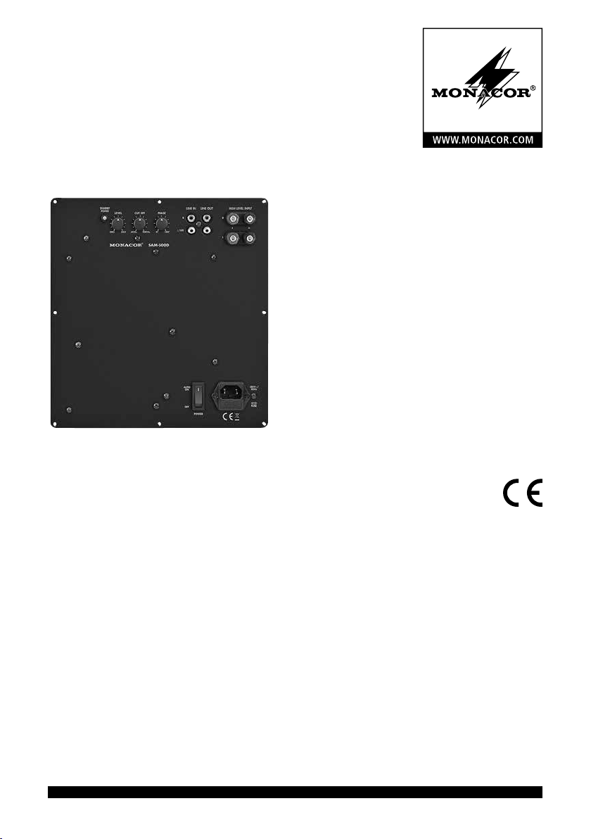
Verstärker-Einbaumodul
für Subwoofer
Amplifier Insertion Module
for Subwoofers
SAM-500D
Bestell-Nr. • Order No. 32.0800
BEDIENUNGSANLEITUNG
INSTRUCTION MANUAL
ELECTRONICS FOR SPECIALISTS ELECTRONICS FOR SPECIALISTS ELECTRONICS FOR SPECIALISTS ELECTRONICS FOR SPECIALISTS
Page 2

Page 3

Deutsch
1 Übersicht der Bedienelemente und Anschlüsse . 4
2 Hinweise für den sicherenGebrauch .......... 5
3 Einsatzmöglichkeiten ...................... 5
4 Montage und Anschluss .................... 5
4.1 Signalquelle anschließen ..................... 6
4.2 Signalausgang ............................. 6
4.3 Stromversorgung ........................... 6
5 Bedienung ............................... 6
6 Technische Daten .......................... 7
English
1 Operating Elements andConnections ......... 8
2 Safety Notes .............................. 9
3 Applications .............................. 9
4 Installation and Connection ................. 9
4.1 Connecting a signal source .................. 10
4.2 Signal output ............................. 10
4.3 Power supply .............................10
5 Operation ............................... 10
6 Specifications ............................ 11
ELECTRONICS FOR SPECIALISTS ELECTRONICS FOR SPECIALISTS ELECTRONICS FOR SPECIALISTS ELECTRONICS FOR SPECIALISTS
3
Page 4
1 2 3 4 5 6
7
Verstärker-Einbaumodul
für Subwoofer
Diese Anleitung richtet sich an Selbstbau-
Deutsch
Amateure von Lautsprecherboxen mit entsprechenden Grundkenntnissen. Bitte lesen Sie die
Anleitung vor dem Betrieb gründlich durch und
heben Sie sie für ein späteres Nachlesen auf.
STANDBY
POWER
1 Übersicht der Bedienelemente
und Anschlüsse
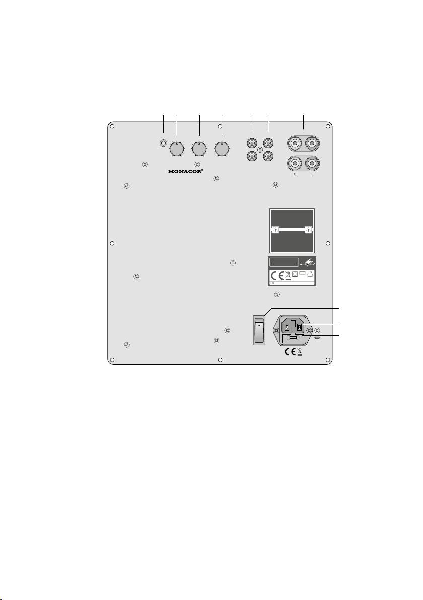
1 LED für den Betriebszustand
rot = Stand-by (Bereitschaft)
grün = Endstufe eingeschaltet
2 Lautstärkeregler LEVEL
3 Regler CUT OFF zum Einstellen der Grenz-
frequenz für den Subwoofer
4
Regler PHASE zum Einstellen der Phasenver
schiebung des Ausgangssignals gegenüber
dem Eingangssignal
5 Eingang LINE IN als Cinch-Buchsen für Sig-
nale mit Line-Pegel; beim Anschluss beider
Buchsen (z. B. Stereosignal) wird intern aus
den Signalen die Summe (Mono) gebildet.
4
LEVEL
PHASE
LINE IN LINE OUT
R
L/ LFE
-180°0°
CUT OFF
MAXMIN
200Hz40Hz
SAM-500D
HIGH LEVEL INPUT
R
L
ACHTUNG! Vor Önen des Gerätes Netzstecker ziehen,
Netzleitung und Netzsicherung nur von Fachpersonal wechseln
lassen. Gerät vor Feuchtigkeit und Hitze schützen. Zulässiger
Einsatztemperaturbereich 0
Gerät nur für den angegebenen Zweck verwenden.
CAUTION! Remove the mains plug before opening the unit. Leave
replacing of the mains supply cord and mains fuse to qualied
service personnel. Protect the unit against moisture and heat.
Permissible operating temperature range 0-40°C. This product is
not intended
for use other than stated.
ATTENTION! Avant d'ouvrir
l'appareil, retirez la che secteur d'alimentation. Toute
intervention sur le câble secteur et le fusible secteur doit être
eectuée uniquement par du personnel qualié. Protegez
l'appareil de l'humidité et de la chaleur. Plage autorisée de la
température d'utilisation 0
À n'utiliser que dans le domaine d'application déterminé.
ATTENZIONE! Staccare la spina di rete prima di aprire
l'apparecchio, e far cambiare il cavo di rete ed il fusibile di rete
solo da persona esperta. Proteggere l'apparecchio dall'umidità e
dal calore. Campo della temperatura d'impiego ammessa 0
Usare l'apparecchio solo per lo scopo indicato.
SAM-500D
DIGITAL SUBWOOFER MODU LE
MONACOR INTERNATIONAL • ZUM FALSCH 36 • 28307 BREMEN • GERMANY
T4AL
230V~ / 50H z / 840 VA
-
40°C.
-
40°C.
-
40°C.
8
USE ONLY WITH A 250V FUSE
230V~/
50Hz
9
10
FUSE
AUTO
ON
OFF
POWER
6 Ausgang LINE OUT als Cinch-Buchsen zum
Weiterleiten des Eingangssignals z. B. zu
einem weiteren Verstärker
7
Schraubklemmen HIGH LEVEL INPUT als
Signaleingang zum Anschluss an die Lautsprecherausgänge eines Endverstärkers
[alternativ zu den Cinch-Buchsen LINE IN (5)]
8 Ein- /Ausschalter POWER
-
9
Netzbuchse zum Anschluss an eine Steckdose (230 V/ 50 Hz) über das beiliegende
Netzkabel
10 Halterung für die Netzsicherung
Eine durchgebrannte Sicherung nur durch
eine gleichen Typs ersetzen.
Page 5

2 Hinweise für den
sicherenGebrauch
Das Verstärkermodul entspricht allen relevanten Richtlinien der EU und trägt deshalb das
-Zeichen.
WARNUNG
Verwenden Sie das Modul nur im Innen-
•
bereich und schützen Sie es vor Tropf- und
Spritzwasser, hoher Luftfeuchtigkeit und
Hitze (zulässiger Einsatztemperaturbereich
0 – 40 °C).
Nehmen Sie das Modul nicht in Betrieb oder
•
ziehen Sie sofort den Netzstecker aus der
Steckdose,
1.
wenn sichtbare Schäden am Modul oder
am Netzkabel vorhanden sind,
2.
wenn nach einem Sturz oder Ähnlichem der
Verdacht auf einen Defekt besteht,
3. wenn Funktionsstörungen auftreten.
Geben Sie das Modul in jedem Fall zur Reparatur in eine Fachwerkstatt.
Ziehen Sie den Netzstecker nie am Kabel aus
•
der Steckdose, fassen Sie immer am Stecker
an.
Verwenden Sie für die Reinigung nur ein tro-
•
ckenes, weiches Tuch, niemals Wasser oder
Chemikalien.
Wird das Modul zweckentfremdet, nicht
•
richtig installiert, falsch bedient, verändert
oder nicht fachgerecht repariert, kann keine
Haftung für daraus resultierende Sach- oder
Personenschäden und keine Garantie für das
Modul übernommen werden.
Das Modul wird mit lebensgefährlicher Netzspannung versorgt. Schließen Sie das Modul
erst nach dem Einbau ans Netz
an. Anderenfalls besteht die Gefahr eines elektrischen Schlages.
Soll das Modul endgültig aus dem Betrieb genommen werden, übergeben
Sie es zur umweltgerechten Entsorgung
einem örtlichen Recyclingbetrieb.
3 Einsatzmöglichkeiten
Dieses Verstärkermodul ist für den Einbau in
eine Subwoofer-Lautsprecherbox vorgesehen.
Diese dient dann als tieffrequente Ergänzung
bestehender Lautsprecheranlagen, wenn eine
überzeugende Basswiedergabe gefordert ist.
Das Modul verfügt über ein Tiefpassfilter mit
einer einstellbaren Grenzfrequenz (40 – 200 Hz)
und einen Regler zur Phasenkorrektur im Zusammenhang mit anderen Lautsprechern. Der
Verstärker ist mit einem Pegelbegrenzer (Limiter)
zum Schutz des Lautsprechers ausgestattet.
Die Endstufe ist als Klasse-D-Verstärker ausgeführt und wird von einem Schaltnetzteil versorgt, wodurch ein besonders hohen Wirkungsgrad bei einem geringen Gewicht erreicht wird.
Alternativ zum Anschluss an Signalquellen
mit Line-Pegel kann das Modul auch an die Lautsprecherausgänge eines Endverstärkers angeschlossen werden.
4 Montage und Anschluss
WARNUNG Trennen Sie das Verstärker modul
vor dem Einbau unbedingt vom
Netz. Das Modul darf nur im eingebauten Zustand betrieben werden. Anderenfalls besteht die Gefahr eines elektrischen Schlages.
1) Für den Einbau des Moduls in die Lautspre-
cherbox einen passenden Ausschnitt sägen
(ca. 225 mm × 248 mm).
2)
Es dürfen nur Lautsprecher bzw. Lautsprechersysteme mit einer Gesamtimpedanz von
mindestens 4 Ω angeschlossen werden. Den
Lautsprecher über die beiden von der Leiterplatte kommenden Kabel verbinden. Dabei
auf die richtige Polung achten: den Lautsprecherpluspol an das rote Kabel (Leiterplattenbeschriftung „SP+“), den Minuspol an das
schwarze Kabel (Leiterplattenbeschriftung
„SP–“) anschließen.
3)
Das Modul in die Lautsprecherbox einsetzen. Stellen Sie sicher, dass das Modul im
Innern der Box ausreichend Platz hat und
nicht von anderen elektrisch leitenden Teilen
oder hitze empfindlichen Materialien berührt
wird. Die erforderliche Einbautiefe beträgt bei
nicht versenkter Frontplatte 76 mm. Achten
Deutsch
5
Page 6

Sie auch darauf, dass die Anschlusskabel
nicht gedehnt oder gequetscht werden.
4) Die Frontplatte des Moduls mit acht Schrau-
Deutsch
ben (∅ 4 mm) an der Box festschrauben.
5)
Bei der Aufstellung eines einzelnen Subwoofers ist die genaue Positionierung in der Mitte
zwischen den Stereo-Lautsprechern nicht
entscheidend, da die von ihm wiedergegebenen sehr tiefen Frequenzen nicht genau
geortet werden können. Stellen Sie ihn jedoch nicht zu dicht an Wände oder in Ecken,
weil dies den Frequenzgang verfälscht.
Vor dem Anschluss bzw. vor dem Ändern bestehender Anschlüsse das Verstärkermodul und die
anzuschließenden Geräte ausschalten.
4.1 Signalquelle anschließen
Eine Signalquelle mit Line-Pegel (z. B. Ausgang vom Mischpult oder Vorverstärker) an die
Cinch-Buchsen LINE IN (5) anschließen. Beim
Anschluss einer Stereo-Signalquelle wird intern
ein Monosignal erzeugt. Die Buchse L / LFE
kann auch mit einem LFE-Ausgang verbunden werden. In Mehrkanalsystemen aus dem
Kinobereich, z. B. „5.1“, dient der LFE-Kanal
zur Übertragung tieffrequenter Spezialeffekte
(„Low Frequency Effect“ oder „Low Frequency
Enhancement“).
Alternativ können die Schraubklemmen
HIGH LEVEL INPUT (7) mit den Lautsprecherausgängen eines Endverstärkers verbunden werden
[parallel zu den dort angeschlossenen Lautsprechern]. Den linken Kanal an das Klemmenpaar
„L“, den rechten an „R“ anschließen. Dabei auf
die richtige Polung achten: Jeweils den Pluspol
(gekennzeichnete Lautsprecherkabelader) mit
der roten Klemme verbinden.
Vorsicht!
Schließen Sie an die Klemmen HIGH LEVEL
•
INPUT nur Verstärker mit einer maximalen
Ausgangsspannung von 2 × 20 V (das entspricht einer Ausgangsleistung von 2 × 100 W
an 4 Ω oder 2 × 50 W an 8 Ω) an.
Achten Sie beim Anschluss der Schraubklem-
•
men darauf, dass die Kabelenden nicht zu
weit abisoliert sind und keine blanken Drähte
herausragen (Berührungs- und Kurzschlussgefahr).
4.2 Signalausgang
An den Cinch-Buchsen LINE OUT (6) steht das
Eingangssignal zum Weiterleiten zu einem weiteren Verstärker oder einer Aktiv-Lautsprecherbox zur Verfügung. Dieses Ausgangssignal wird
nicht von den Reglern LEVEL (2), CUT OFF (3)
und PHASE (4) beeinflusst.
4.3 Stromversorgung
Das beiliegende Netzkabel an die Netzbuchse (9)
anschließen und den Stecker in eine Steckdose
(230 V/ 50 Hz) stecken.
5 Bedienung
VORSICHT
Hinweis: Um Schaltgeräusche zu vermeiden, das Ver-
stärkermodul immer nach der ange schlossenen Signalquelle einschalten und nach dem Gebrauch als Erstes
ausschalten.
1)
Den Regler LEVEL (2) vor dem ersten Einschalten zunächst auf Minimum (Linksanschlag)
stellen und den Verstärker mit dem Schalter
POWER (8) einschalten. Solange kein Signal
anliegt, ist das Modul im stromsparenden
Bereitschaftsmodus (Stand-by) und die LED
STANDBY / POWER (1) leuchtet rot. Sobald ein
Signal anliegt, schaltet sich die Endstufe ein
und die LED leuchtet grün.
2)
Über die bestehende Lautsprecheranlage
z. B. Musik wiedergeben und mit dem Regler LEVEL (2) den gewünschten Tiefbassanteil
dazumischen. Den Regler nur so weit aufdrehen, dass der Ton nicht verzerrt wiedergegeben wird.
3)
Mit dem Regler CUT OFF (3) die obere Grenzfrequenz des Subwoofers so einstellen, dass
dieser den Frequenzgang der anderen Lautsprecher optimal ergänzt.
Stellen Sie die Lautstärke der
Lautsprecheranlage nie sehr hoch
ein. Hohe Lautstärken können
auf Dauer das Gehör schädigen!
Das Ohr gewöhnt sich an sie und
empfindet sie nach einiger Zeit als
nicht mehr so hoch. Darum eine
hohe Lautstärke nach der Gewöhnung nicht weiter erhöhen.
6
Page 7

4)
Bei unterschiedlichen Abständen der Lautsprecher zum Hörer kann es zu Phasenauslöschungen kommen (bestimmte Frequenzen
werden dadurch leiser). Zum Ausgleich kann
mithilfe des Reglers PHASE (4) die Phase des
Subwoofersignals verschoben werden.
Durch Probieren herausfinden, bei welcher Reglerstellung an der Hörposition die
lauteste Basswiedergabe erreicht wird. Wenn
erforderlich, anschließend die Lautstärkebalance mit dem Regler LEVEL (2) korrigieren.
5) Liegt länger als ca. 25 Minuten kein Signal
am Eingang an, schaltet das Verstärkermodul in den Bereitschaftsmodus: Die LED
STANDBY / POWER (1) leuchtet rot. Bei längeren Betriebspausen das Verstärkermodul mit
dem Schalter POWER ausschalten.
6 Technische Daten
Ausgangsleistung an 4 Ω / 8 Ω
Sinusleistung: . . . . . . 500 W/ 250 W
Spitzenleistung: . . . . . 700 W/ 350 W
Frequenzbereich (obere
Grenzfrequenz variabel): 20 – 40 … 200 Hz
Lastimpedanz: . . . . . . . . 4 – 8 Ω
Eingangsimpedanz
LINE IN: . . . . . . . . . . . 22 kΩ
HIGH LEVEL INPUT: . . 270 Ω
Eingangsempfindlichkeit
LINE IN: . . . . . . . . . . . 170 mV
HIGH LEVEL INPUT: . . 1 V
max. Eingangsspannung
LINE IN: . . . . . . . . . . . 7 V
HIGH LEVEL INPUT: . . 20 V
Klirrfaktor: . . . . . . . . . . < 1 %
Störabstand: . . . . . . . . . > 70 dB
Stromversorgung: . . . . . 230 V/ 50 Hz
Leistungsaufnahme
Volllast: . . . . . . . . . . . 840 VA
Leerlauf: . . . . . . . . . . 38 VA
Stand-by: . . . . . . . . . . 0,5 W
Einsatztemperatur: . . . . 0 – 40 °C
Abmessungen: . . . . . . . 251 × 270 × 90 mm
Gewicht . . . . . . . . . . . . 2,5 kg
Deutsch
Änderungen vorbehalten.
Diese Bedienungsanleitung ist urheberrechtlich für MONACOR ® INTERNATIONAL GmbH & Co. KG geschützt. Eine
Reproduktion für eigene kommerzielle Zwecke – auch auszugsweise – ist untersagt.
7
Page 8

1 2 3 4 5 6
7
Amplifier Insertion Module
forSubwoofers
These instructions are intended for non-pro-
English
fessionals with basic knowledge in DIY speaker
building. Please read the instructions carefully
prior to operation and keep them for later
reference.
STANDBY
POWER
LEVEL
CUT OFF
MAXMIN
1 Operating Elements
andConnections
1 Status LED
red = standby
green = power amplifier switched on
2 LEVEL control
3
CUT OFF control to set the cut-off frequency
for the subwoofer
4 PHASE control to shift the phase of the out-
put signal compared to the input signal
5
Input LINE IN (RCA jacks) for signals with line
level; when both jacks are connected (e. g.
stereo signal), the signals internally create a
sum signal (mono)
HIGH LEVEL INPUT
R
L
ACHTUNG! Vor Önen des Gerätes Netzstecker ziehen,
Netzleitung und Netzsicherung nur von Fachpersonal wechseln
lassen. Gerät vor Feuchtigkeit und Hitze schützen. Zulässiger
Einsatztemperaturbereich 0
Gerät nur für den angegebenen Zweck verwenden.
CAUTION! Remove the mains plug before opening the unit. Leave
replacing of the mains supply cord and mains fuse to qualied
service personnel. Protect the unit against moisture and heat.
Permissible operating temperature range 0-40°C. This product is
not intended
for use other than stated.
ATTENTION! Avant d'ouvrir
l'appareil, retirez la che secteur d'alimentation. Toute
intervention sur le câble secteur et le fusible secteur doit être
eectuée uniquement par du personnel qualié. Protegez
l'appareil de l'humidité et de la chaleur. Plage autorisée de la
température d'utilisation 0
À n'utiliser que dans le domaine d'application déterminé.
ATTENZIONE! Staccare la spina di rete prima di aprire
l'apparecchio, e far cambiare il cavo di rete ed il fusibile di rete
solo da persona esperta. Proteggere l'apparecchio dall'umidità e
dal calore. Campo della temperatura d'impiego ammessa 0
Usare l'apparecchio solo per lo scopo indicato.
SAM-500D
DIGITAL SUBWOOFER MODU LE
MONACOR INTERNATIONAL • ZUM FALSCH 36 • 28307 BREMEN • GERMANY
T4AL
230V~ / 50H z / 840 VA
-
40°C.
-
40°C.
-
40°C.
200Hz40Hz
SAM-500D
PHASE
LINE IN LINE OUT
R
L/ LFE
-180°0°
8
USE ONLY WITH A 250V FUSE
230V~/
50Hz
9
10
FUSE
AUTO
ON
OFF
POWER
6 Output LINE OUT (RCA jacks) to route the
input signal e. g. to another amplifier
7 Screw terminals HIGH LEVEL INPUT as a sig-
nal input to connect the speaker outputs of
a power amplifier [instead of using the RCA
jacks LINE IN (5)]
8 POWER switch
9
Mains jack for connection to a socket
(230 V/ 50 Hz) via the mains cable provided
10 Support for the mains fuse
Always replace a blown fuse by one of the
same type.
8
Page 9

2 Safety Notes
The amplifier module corresponds to all relevant
directives of the EU and is therefore marked
with .
WARNING
The module is suitable for indoor use only.
•
Protect it against dripping water and splash
water, high air humidity and heat (admissible
ambient temperature range 0 – 40 °C).
Do not operate the module or immediately
•
disconnect the mains plug from the socket
1. if the module or the mains cable is visibly
damaged,
2.
if a defect might have occurred after the
unit was dropped or suffered a similar accident,
3. if malfunctions occur.
In any case the module must be repaired by
skilled personnel.
Never pull the mains cable to disconnect the
•
mains plug from the socket, always seize the
plug.
For cleaning only use a dry, soft cloth; never
•
use water or chemicals.
No guarantee claims for the module and no
•
liability for any resulting personal damage or
material damage will be accepted if the module is used for other purposes than originally
intended, if it is not correctly installed or operated, if it is modified or if it is not repaired
in an expert way.
The module uses dangerous
mains voltage. Install the module
before connecting it to the mains;
otherwise you will risk an electric
shock.
If the module is to be put out of operation definitively, take it to a local recycling plant for a disposal which is not
harmful to the environment.
3 Applications
This amplifier module is designed for installation into a subwoofer speaker cabinet which is
used to complement existing speaker systems
with low frequencies when a convincing bass
reproduction is required.
The module is provided with a low-pass filter
with adjustable cut-off frequency (40 – 200 Hz)
and a control to correct the phase in combination with other speakers. The amplifier has a
limiter to protect the speaker.
The power amplifier is designed as a class
Damplifier. It is supplied with power from a
switch-mode power supply. Thus, it has an extra
high efficiency at a low weight.
Instead of connecting the module to signal sources with line level, it is also possible to
connect it to the speaker outputs of a power
amplifier.
4 Installation and Connection
WARNING
1) To install the module, saw a suitable cutout
(approx. 225 mm × 248 mm) into the speaker
cabinet.
2)
Only connect speakers or speaker systems
with a total impedance of at least 4 Ω. Connect the speaker via the two cables coming
from the PCB. Always observe the correct
polarity: connect the positive pole of the
speaker to the red cable (marked “SP+” on
the PCB); connect the negative pole to the
black cable (marked “SP–” on the PCB).
3) Insert the module into the speaker cabinet.
Make sure that there is sufficient space for
the module inside the cabinet and that there
is no risk of contact with other electroconductive components or heat-sensitive materials. When the front plate is not recessed,
the required mounting depth is 76 mm. Do
not stretch or squeeze the connection cables.
4)
Use eight screws (∅ 4 mm) to fasten the front
plate of the module to the cabinet.
When installing the amplifier
module, always disconnect it
from the mains. For operation,
the module must always be installed; otherwise you will risk an
electric shock.
English
9
Page 10

5)
When setting up a single subwoofer, it is not
important to place the subwoofer exactly in
the middle between the stereo speakers as
English
it will not be possible to precisely locate the
very low frequencies reproduced by the subwoofer. However, do not place it too close
to walls or in corners; this would distort the
frequency response.
Prior to making connections or changing any
existing connections, switch off the amplifier
module and the units to be connected.
4.1 Connecting a signal source
Connect a signal source with line level (e. g. output of a mixer or preamplifier) to the RCA jacks
LINE IN (5). When connecting a stereo signal
source, a mono signal is internally created. It
is also possible to connect the jack L / LFE to an
LFE output. In multi-channel systems for cinema applications, e. g. “5.1”, the LFE channel
is used for low-frequency special effects (“Low
Frequency Effect” or “Low Frequency Enhancement”).
Alternatively, connect the screw terminals
HIGH LEVEL INPUT (7) to the speaker outputs
of a power amplifier [in parallel to the speakers
connected there]. Connect the left channel to
the terminal pair “L”, connect the right channel
to “R”. Observe the correct polarity: Always connect the positive pole (marked core of speaker
cable) to the red terminal.
Caution!
Only connect amplifiers with a maximum out-
•
put voltage of 2 × 20 V (corresponding to an
output power of 2 × 100 W at 4 Ω or 2 × 50 W
at 8 Ω) to these terminals.
When connecting the screw terminals, make
•
sure that the cable ends are only stripped for
the length required and that no bare wires
protrude (hazard of contact and short circuit).
4.2 Signal output
At the RCA jacks LINE OUT (6), the input signal
is available for being routed to another amplifier
or active speaker system. The position of the
controls LEVEL (2), CUT OFF (3) and PHASE (4)
has no effect on this output signal.
4.3 Power supply
Connect the mains cable provided to the
mains jack (9) and the plug to a mains socket
(230 V/ 50 Hz).
5 Operation
CAUTION Never adjust the speaker system
to a very high volume. Permanent
high volumes may damage your
hearing! Your ear will get accustomed to high volumes which do
not seem to be that high after
some time. Therefore, do not further increase a high volume after
getting used to it.
Note: To prevent switching noise, always switch on
the signal source connected before switching on the
amplifier module. After use, switch off the amplifier
module first.
1) Before switching on for the first time, set the
LEVEL control (2) to minimum (left stop) for
the time being. Switch on the amplifier with
the POWER switch (8). As long as no signal
is applied, the module is on standby to save
power and the LED STANDBY/POWER (1)
shows red. As soon as a signal is applied, the
power amplifier is switched on and the LED
shows green.
2)
Via the existing speaker system, reproduce
music, for example, and add the desired low
bass part with the LEVEL control (2). Only
turn up the control to such an extent that the
sound reproduced is not distorted.
3) Use the control CUT OFF (3) to set the upper
cut-off frequency of the subwoofer in such
10
Page 11

a way that it will optimally complement the
frequency response of the other speakers.
4)
When the speakers are placed at different
distances to the listener, phase cancellation
may result (certain frequencies are reproduced at a lower volume). To compensate
this effect, shift the phase of the subwoofer
signal with the control PHASE (4).
Test the positions of the control to find
the one offering the bass reproduction of
the highest volume at the listening position.
Then readjust the volume balance with the
LEVEL control (2), if required.
5)
If there is no signal at the input for more than
approx. 25 minutes, the amplifier module
goes on standby: The LED STANDBY / POWER
(1) shows red. If the amplifier module is not in
use for longer intervals, switch off the amplifier module with the POWER switch.
6 Specifications
Amplifier power at 4 Ω / 8 Ω
RMS power: . . . . . . . 500 W/ 250 W
Peak power: . . . . . . . 700 W/ 350 W
Frequency range
(upper cut-off frequency
is variable): . . . . . . . . . . 20 – 40 … 200 Hz
Load impedance: . . . . . 4 – 8 Ω
Input impedance
LINE IN: . . . . . . . . . . . 22 kΩ
HIGH LEVEL INPUT: . . 270 Ω
Input sensitivity
LINE IN: . . . . . . . . . . . 170 mV
HIGH LEVEL INPUT: . . 1 V
Input voltage max.
LINE IN: . . . . . . . . . . . 7 V
HIGH LEVEL INPUT: . . 20 V
THD: . . . . . . . . . . . . . . . < 1 %
S / N ratio: . . . . . . . . . . . > 70 dB
Power supply: . . . . . . . . 230 V/ 50 Hz
Power consumption
Full load: . . . . . . . . . . 840 VA
No-load: . . . . . . . . . . 38 VA
Standby: . . . . . . . . . . 0.5 W
Ambient temperature: . 0 – 40 °C
Dimensions: . . . . . . . . . 251 × 270 × 90 mm
Weight: . . . . . . . . . . . . 2.5 kg
English
Subject to technical modification.
All rights reserved by MONACOR ® INTERNATIONAL GmbH & Co. KG. No part of this instruction manual may be
reproduced in any form or by any means for any commercial use.
11
Page 12

MONACOR INTERNATIONAL GmbH & Co. KG • Zum Falsch 36 • 28307 Bremen • Germany
Copyright © by MONACOR INTERNATIONAL. All rights reserved. A-1374.99.02.02.2017
 Loading...