

Page 1

SAM-1
Best.-Nr. 32.0640
BEDIENUNGSANLEITUNG
INSTRUCTION MANUAL
MODE D’EMPLOI
ISTRUZIONI PER L’USO
GEBRUIKSAANWIJZING
MANUAL DE INSTRUCCIONES
INSTRUKCJA OBSŁUGI
SIKKERHEDSOPLYSNINGER
SÄKERHETSFÖRESKRIFTER
TURVALLISUUDESTA
AKTIV-SUBWOOFER-BAUSTEIN
ACTIVE SUBWOOFER MODULE
Page 2

2
Bevor Sie einschalten …
Wir wünschen Ihnen viel Spaß mit Ihrem neuen
Gerät von MONACOR. Bitte lesen Sie diese
Bedienungsanleitung vor dem Betrieb gründlich
durch. Nur so lernen Sie alle Funktionsmöglichkeiten kennen, vermeiden Fehlbedienungen und
schützen sich und Ihr Gerät vor eventuellen Schäden durch unsachgemäßen Gebrauch. Heben
Sie die Anleitung für ein späteres Nachlesen auf.
Der deutsche Text beginnt auf der Seite 4.
Before switching on …
We wish you much pleasure with your new
MONACOR unit. Please read these operating
instructions carefully prior to operating the unit.
Thus, you will get to know all functions of the unit,
operating errors will be prevented, and yourself
and the unit will be protected against any damage
caused by improper use. Please keep the operating instructions for later use.
The English text starts on page 8.
Avant toute installation …
Nous vous souhaitons beaucoup de plaisir à utiliser cet appareil MONACOR. Lisez ce mode
dʼemploi entièrement avant toute utilisation. Uniquement ainsi, vous pourrez apprendre lʼen semble des possibilités de fonctionnement de
lʼappareil, éviter toute manipulation erronée et
vous protéger, ainsi que lʼappareil, de dommages
éventuels engendrés par une utilisation inadaptée. Conservez la notice pour pouvoir vous y
reporter ultérieurement.
La version française se trouve page 11.
Prima di accendere …
Vi auguriamo buon divertimento con il vostro
nuovo apparecchio di MONACOR. Leggete at tentamente le istruzioni prima di mettere in funzione lʼapparecchio. Solo così potete conoscere
tutte le funzionalità, evitare comandi sbagliati e
proteggere voi stessi e lʼapparecchio da eventuali danni in seguito ad un uso improprio. Conservate le istruzioni per poterle consultare anche
in futuro.
Il testo italiano inizia a pagina 14.
D
A
CH
GB
Antes de la utilización …
Le deseamos una buena utilización para su
nuevo aparato MONACOR. Por favor, lea estas
in s trucciones de uso atentamente antes de hacer
funcionar el aparato. De esta manera conocerá
todas las funciones de la unidad, se prevendrán
errores de operación, usted y el aparato estarán
protegidos en contra de todo daño causado por
un uso inadecuado. Por favor, guarde las instrucciones para una futura utilización.
La versión española comienza en la página 17.
Voor u inschakelt …
Wij wensen u veel plezier met uw nieuwe apparaat van MONACOR. Lees de veiligheidsvoorschriften grondig door, alvorens het apparaat in
gebruik te nemen. Zo behoedt u zichzelf en het
apparaat voor eventuele schade door ondeskundig gebruik. Bewaar de handleiding voor latere
raadpleging.
De veiligheidsvoorschriften vindt u op pagina 24.
Przed uruchomieniem …
Życzymy zadowolenia z nowego produktu
MONACOR. Dzięki tej instrukcji obsługi będą
państwo w stanie poznać wszystkie funkcje tego
urządzenia. Stosując się do instrukcji unikną
państwo błędów i ewentualnego uszkodzenia
urządzenia na skutek nieprawidłowego użytkowania. Prosimy zachować instrukcję.
Tekst polski zaczyna się na stronie 20.
Før du tænder …
Tillykke med dit nye MONACOR produkt. Læs
sikkerhedsanvisningerne nøje før ibrugtagning,
for at beskytte Dem og enheden mod skader, der
skyldes forkert brug. Gem manualen til senere
brug.
Sikkerhedsanvisningerne findes på side 24.
Innan du slår på enheten …
Vi önskar dig mycket glädje med din nya
MONACOR produkt. Läs igenom säkerhetsföreskrifterna innan enheten tas i bruk för att undvika
skador till följd av felaktig hantering. Behåll instruktionerna för framtida bruk.
Säkerhetsföreskrifterna återfinns på sidan 25.
Ennen kytkemistä …
Toivomme Sinulle paljon miellyttäviä hetkiä
uuden MONACOR laitteen kanssa. Ennen laitteen käyttöä pyydämme Sinua huolellisesti tutustumaan turvallisuusohjeisiin. Näin vältyt vahingoilta, joita virheellinen laitteen käyttö saattaa
aiheuttaa. Ole hyvä ja säilytä käyttöohjeet myöhempää tarvetta varten.
Turvallisuusohjeet löytyvät sivulta 25.
F
B
CH
I
E
PL
DK
S FIN
NL
B
Page 3
3
230V~ /50 Hz/120VA
POWER
LEFT
RIGHT
HIGH LEVEL INPUT
RIGHT
LEFT
LINE IN
GROUND LIFT
50Hz
150 Hz
100 Hz
LEVEL
PHASE
CROSSOVER
010
0∞
180∞
T 2 AL
www.monacor.com
SAM-1 SUBWOOFER ACTIVE MODULE
12 0 W
OFF
GND
11 12
OUTPUT
OUT
-
OUT+
S2
Fullrange
Subwoofer
1
2
3
4
5
6
7
8
9
10
Page 4
4
CH
A
D
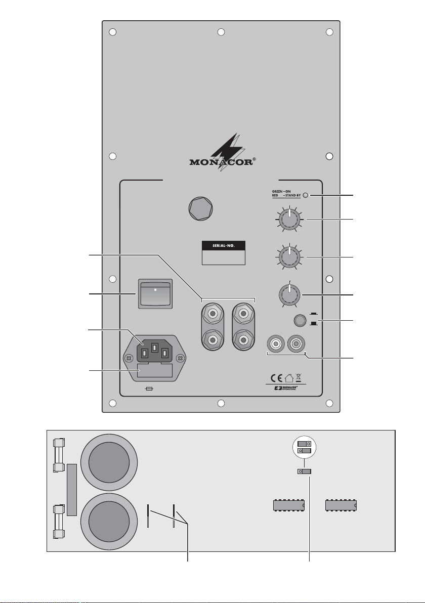
Auf der ausklappbaren Seite 3 finden Sie alle be schriebenen Bedienelemente und Anschlüsse.
1 Übersicht der Anschlüsse
und Bedienelemente
1.1 Frontseite
1 Buchsen HIGH LEVEL INPUT für den Signalein-
gang zum Anschluss an die Lautsprecherausgänge eines Endverstärkers [alternativ zu den
Cinch-Buchsen LINE IN (10)]
2 Ein- /Ausschalter POWER
3 Netzbuchse zum Anschluss an eine Steckdose
(230 V~ / 50 Hz) über das beiliegende Netzkabel
4 Halterung für die Netzsicherung
Eine geschmolzene Sicherung nur durch eine gleichen Typs ersetzen.
5 LED für den Betriebszustand
rot = Stand-by (Bereitschaft)
grün = Endstufe eingeschaltet
6 Lautstärkeregler LEVEL
7 Regler PHASE zum Einstellen der Phasenlage
zwischen dem Ein- und Ausgangssignal der Aktivbox (nur bei Subwoofer-Betrieb)
8 Regler CROSSOVER zum Einstellen der Trennfre-
quenz (nur bei Subwoofer-Betrieb)
9 Groundlift-Schalter
Taste nicht gedrückt
Signalmasse und Frontplatte / Schutzleiter sind
elektrisch verbunden
Taste gedrückt
Signalmasse und Frontplatte / Schutzleiter sind
getrennt
10 Cinch-Buchsen LINE IN für ein Eingangssignal mit
Line-Pegel [alternativ zu den Buchsen HIGH
LEVEL INPUT (1)]
1.2 Leiterplatte
11 Lautsprecheranschluss
12 Steckbrücke zum Einstellen des Betriebsmodus
Position „Subwoofer“
Betrieb als Subwoofer-Box; es werden nur die
Bässe über den angeschlossenen Lautsprecher
wiedergegeben
Position „Fullrange“
Betrieb als Vollbereichsbox; es werden alle Frequenzen wiedergegeben
2 Hinweise für den sicheren Gebrauch
Das Gerät entspricht allen erforderlichen Richtlinien
der EU und ist deshalb mit gekennzeichnet.
Beachten Sie auch unbedingt die folgenden Punkte:
G
Verwenden Sie das Gerät nur im In nen bereich und
schützen Sie es vor Tropf- und Spritzwasser, hoher
Luftfeuchtigkeit und Hitze (zu lässiger Einsatztemperaturbereich 0 – 40°C).
G
Stellen Sie keine mit Flüssigkeit gefüllten Gefäße,
z. B. Trinkgläser, auf das Gerät.
G
Nehmen Sie das Gerät nicht in Betrieb und ziehen
Sie sofort den Netzstecker aus der Steckdose,
1. wenn sichtbare Schäden am Gerät oder an der
Netzanschlussleitung vorhanden sind,
2. wenn nach einem Sturz oder Ähnlichem der Verdacht auf einen Defekt besteht,
3. wenn Funktionsstörungen auftreten.
Geben Sie das Gerät in jedem Fall zur Reparatur in
eine Fachwerkstatt.
G
Ziehen Sie den Netzstecker nie am Kabel aus der
Steckdose, fassen Sie immer am Stecker an.
G
Verwenden Sie für die Reinigung nur ein trockenes,
weiches Tuch, niemals Wasser oder Chemikalien.
G
Wird das Gerät zweckentfremdet, nicht richtig montiert, falsch angeschlossen bzw. be dient oder nicht
fachgerecht re pa riert, kann keine Haftung für daraus
resultierende Sach- oder Personenschäden und
keine Garantie für das Gerät übernommen werden.
Soll das Gerät endgültig aus dem Betrieb
genommen werden, übergeben Sie es zur
umweltgerechten Entsorgung einem örtlichen Recyclingbetrieb.
WARNUNG Das Gerät wird mit lebensgefähr -
licher Netzspannung (230 V~) versorgt.
Achten Sie beim Einbau des Bausteins
in eine Lautsprecherbox unbedingt da rauf, dass der Baustein nicht mit der
Netzspannung verbunden ist. Den Netzstecker aus der Steckdose ziehen! Anderenfalls besteht die Gefahr eines lebensgefährlichen elektrischen Schlages.
Page 5
3 Verwendungsmöglichkeiten
Der Baustein SAM-1 ist eine komplett aufgebaute
120-W-Verstärkerendstufe mit Netzteil und für den
Einbau in eine 4-Ω- oder 8-Ω-Lautsprecherbox konzipiert. Durch die integrierte 12-dB-Subwoofer-Fre quenz weiche lässt sich sowohl eine Aktiv-SubwooferBox als auch eine Aktiv-Vollbereichsbox realisieren.
Der Baustein und der angeschlossene Lautsprecher
werden durch ein 24-dB-Subsonic-Filter und umfassende Schutzschaltungen (gegen Kurzschluss, Überhitzung, Gleichspannungsüberlagerung am Ausgang)
geschützt.
Der besondere Vorteil des SAM-1 beim Einsatz als
Subwoofer ist, dass dieser Aktiv-Subwoofer an jeder
Stelle im Hörraum aufgestellt werden kann. Durch entsprechende Regler für den Pegel und die Phaselage
lässt er sich optimal an die Hauptlautsprecher an passen.
4 Montage
1) Für den Einbau des Bausteins in die Lautsprecher-
box einen Ausschnitt von 140 × 250mm sägen. Die
erforderliche Einbautiefe beträgt bei nicht versenk-
ter Frontplatte 90 mm.
2) Vor dem Einbau mit der Steckbrücke S 2 (12) auf
der Leiterplatte den Betriebsmodus einstellen:
Position „Subwoofer“
Betrieb als Subwoofer-Box; es werden nur die
Bässe über den angeschlossenen Lautsprecher
wiedergegeben
Position „Fullrange“
Betrieb als Vollbereichsbox; es werden alle Frequenzen wiedergegeben
3) Es dürfen nur Lautsprecher bzw. Lautsprecher -
systeme mit einer Gesamtimpedanz von mindes-
tens 4 Ω angeschlossen werden. Den Lautsprecher
über Flachstecker mit dem Anschluss OUTPUT
(11) auf der Leiterplatte verbinden. Dabei auf die
richtige Polung achten, d. h. den Lautsprecher -
pluspol an den Kontakt OUT+ anschließen.
4) Den Baustein mit zehn M4-Schrauben an der Box
festschrauben.
5 Bedienung
5.1 Gerät anschließen
Vor dem Anschließen der Signalquelle bzw. vor dem
Ändern bestehender Anschlüsse die Aktivbox ausschalten!
Der Baustein SAM-1 hat zwei Eingänge zur Verfügung:
1. Die Cinch-Buchsen LINE IN (10) für Signale mit
Line-Pegel zum Anschluss von z.B. Vorverstärker,
Mischpult, Equalizer, Effektgerät usw.
2. Die Apparatebuchsen HIGH LEVEL INPUT (1) für
den Anschluss an die Lautsprecherausgänge eines
Endverstärkers
Wichtig: Werden die Apparatebuchsen verwendet,
darf die Ausgangsleistung des angeschlossenen
Endverstärkers nicht 272 W pro Kanal an 4-ΩLautsprechern bzw. 136W pro Kanal an 8-ΩLautsprechern überschreiten, sonst kommt es
durch Übersteuerung zu Signalverzerrungen.
Am einfachsten und sichersten ist der Anschluss über
ein Cinch-Kabel an den Buchsen LINE IN. Nur wenn
kein Line-Signal zur Verfügung steht, sollten die Eingänge HIGH LEVEL INPUT verwendet werden. Diesen Eingang über Lautsprecherkabel mit den Lautsprechern des Endverstärkers parallelschalten.
Beim Einsatz als Subwoofer- oder Mono-Aktivbox
immer den linken und den rechten Kanal der Signalquelle anschließen. Beide Kanäle werden intern zu
einem Monosignal zusammengeführt. Beim Einsatz
als Vollbereichsbox für einen Stereokanal nur den linken bzw. den rechten Kanal anschließen.
Vorsicht beim Anschluß über die Apparatebuchsen!
a. Bei Endverstärkern mit einer höheren Ausgangs -
leistung als oben angegeben, besteht die Gefahr
eines elektrischen Schlages durch deren hohe Ausgangsspannung.
b. Bei einem versehentlichen Kurzschluss kann der
Endverstärker beschädigt werden.
c. Beim Anschluss auf die richtige Polung achten: Je -
weils den Pluspol (gekennzeichnete Lautsprecher kabel ader) mit der roten Apparatebuchse verbinden.
Zum Schluss das beiliegende Netzkabel zuerst in die
Netzbuchse (3) stecken und dann den Netzstecker in
eine Steckdose (230 V~/ 50 Hz).
WARNUNG
Während der Montage darf der Baustein auf keinen Fall mit der Netzspannung verbunden sein!
5
D
A
CH
Page 6

5.2 Einstellungen vornehmen
Arbeitet die Aktivbox als Subwoofer, können alle Einstellungen und Klangbeurteilungen nur in Verbindung
mit den Hauptlautsprechern erfolgen. Der Klang sollte
am endgültigen Hörplatz beurteilt und durch eine
zweite Person am Aktiv-Subwoofer nach Anweisung
optimal angepasst werden.
1) Mit dem Schalter POWER (2) die Aktivbox einschalten. Solange kein Signal anliegt, ist die Box im
stromsparenden Bereitschaftszustand (Stand-by)
und die Kontroll-LED (5) leuchtet rot. Sobald ein
Signal anliegt, schaltet die Endstufe ein und die
LED leuchtet grün.
Liegt länger als ca. 7 Minuten kein Signal an,
schaltet die Aktivbox wieder auf Bereitschaft zurück
(LED = rot).
2) Ist durch die Verdrahtung eine Masseschleife entstanden, tritt ein Brummen auf (z. B. bei leisen
Musik passagen). Diese Masseschleife lässt sich
mit dem Groundlift-Schalter (9) unterbrechen. Da zu
die Taste einrasten.
Andererseits ist der Verstärker nicht gegen elektrische Störfelder abgeschirmt, wenn das Gehäuse
nicht an Masse liegt. In diesem Fall die GroundliftTaste ausrasten. Im Zweifelsfall die Taste wechselweise schalten, um die optimale Ein stellung zu finden.
3) Arbeitet die Aktivbox als Subwoofer, mit dem Regler CROSSOVER (8) die Trennfrequenz einstellen,
d. h. die Frequenz, die nicht mehr durch den Subwoofer wiedergegeben werden soll (je niedriger die
Trennfrequenz, desto schwerer die akustische
Ortung des Sub woofers; je höher die Trennfrequenz, desto stärker die Bassunterstützung). In den
meisten Fällen werden Regal- und kleine Standlautsprecher optimal er gänzt, wenn die eingestellte
Trennfrequenz zwischen 60 und 100Hz liegt.
Hinweis: Arbeitet die Aktivbox als Vollbereichslautsprecher, ist der Regler CROSSOVER ohne Funktion.
4) Mit dem Regler LEVEL (6) das Lautstärkeverhältnis
zu den übrigen Lautsprechern einstellen. Arbeitet
die Aktivbox als Subwoofer, lässt sich mit dem Regler eine natürliche oder eine bewusst verstärke
Basswiedergabe einstellen.
5) Arbeitet die Aktivbox als Subwoofer, mit dem Regler PHASE (7) die Phasenlage einstellen. Diese
Einstellung ist je nach den akustischen Gegebenheiten stärker oder schwächer wahrnehmbar. Am
besten lässt sich die Phasenlage bei einem Musik stück mit einem E-Baß, einem Kontrabass oder
einer tiefen Bassstimme beurteilen. Den Regler
PHASE auf lauteste Basswiedergabe einstellen.
Hinweis: Arbeitet die Aktivbox als Vollbereichslautsprecher, ist der Regler PHASE ohne Funktion.
6 Technische Daten
Ausgangsleistung
an 4-Ω-Lautsprecher: . . 90 WRMS, 120 WMAX
an 8-Ω-Lautsprecher: . . 65 WRMS, 90 WMAX
Klirrfaktor: . . . . . . . . . . . . . < 0,1 %
Frequenzbereich
Vollrange-Betrieb: . . . . . 20 –20 000 Hz
Subwoofer-Betrieb: . . . . 20 Hz bis einstellbar von
50 – 150Hz
Ausgangsimpedanz: . . . . . 4–8Ω
Eingangsimpedanz
Line In: . . . . . . . . . . . . . 24 kΩ
High Level Input: . . . . . . 17 kΩ
Max. Eingangsspannung
Line In: . . . . . . . . . . . . . 4,7 V mono, 2,3V stereo
High Level Input: . . . . . . 33 V stereo, entspricht
2 × 272 W an 4 Ω oder
2 × 136 W an 8 Ω
Störabstand: . . . . . . . . . . . > 70 dB
Stromversorgung: . . . . . . . 230 V~ / 50 Hz
Leistungsaufnahme
Vollast: . . . . . . . . . . . . . 120 VA
Leerlauf: . . . . . . . . . . . . 2,5 VA
Stand-by: . . . . . . . . . . . . 0,6 VA
Stand-by-Aktivierung: . . . . nach ca. 7 Minuten ohne
Signal
Einsatztemperatur: . . . . . . 0 –40 °C
Erforderlicher
Boxenausschnitt: . . . . . . . . 140 × 250 mm
Einbautiefe,
Frontplatte nicht versenkt: . 90 mm
Abmessungen: . . . . . . . . . 170 × 280 × 95 mm
Gewicht: . . . . . . . . . . . . . . 3,3 kg
Änderungen vorbehalten.
6
D
A
CH
Diese Bedienungsanleitung ist urheberrechtlich für MONACOR®INTERNATIONAL GmbH & Co. KG ge schützt.
Eine Reproduktion für eigene kommerzielle Zwecke – auch auszugsweise – ist untersagt.
Page 7

7
Page 8

All operating elements and connections described
can be found on the fold-out page 3.
1 Operating Elements and Connections
1.1 Front panel
1 HIGH LEVEL INPUT jacks for the signal input for
connecting the speaker outputs of a power amplifier [as an alternative to the phono jacks LINE IN
(10)]
2 POWER switch
3 Mains jack for connecting a mains socket (230 V~ /
50 Hz) via the supplied mains cable
4 Support for the mains fuse
Only replace a blown fuse by one of the same type
5 LED for operating mode
red = stand-by
green = power amplifier switched on
6 Volume control LEVEL
7 PHASE control for adjusting the phase between
the input and the output signals of the active
speaker cabinet (for subwoofer operation only)
8 Control CROSSOVER for adjusting the crossover
frequency (for subwoofer operation only)
9 Groundlift switch
Switch not pressed
Signal ground and front plate / earthed conductor
are electrically connected
Switch pressed
Signal ground and front plate / earthed conductor
are separated
10 LINE IN phono jacks for an input signal with line
level [as an alternative to the HIGH LEVEL INPUT
jacks (1)]
1.2 Printed circuit board
11 Connection for speaker
12 Jumper for adjusting the operating mode
position “Subwoofer”
operation as a subwoofer system; only the bass
frequencies are reproduced via the speaker connected
position “Fullrange”
operation as a full range speaker system; all frequencies are reproduced
2 Safety Notes
The unit corresponds to all required directives of the
EU and is therefore marked with .
Please observe the following items in any case:
G
The unit is suitable for indoor use only. Protect it
against dripping water and splash water, high air
humidity, and heat (admissible ambient temperature
range 0 – 40°C).
G
Do not place any vessels filled with liquid, e. g. drinking glasses, on the unit.
G
Do not set the unit into operation, and immediately
disconnect the mains plug from the mains socket if
1. there is visible damage to the unit or to the mains
cable,
2. a defect might have occurred after a drop or similar accident,
3. there are malfunctions.
The unit must in any case be repaired by skilled personnel.
G
Never pull the mains cable to disconnect the mains
plug from the mains socket, always seize the plug.
G
For cleaning only use a dry, soft cloth, never use
chemicals or water.
G
No guarantee claims for the unit and no liability for
any resulting personal damage or material damage
will be accepted if the unit is used for purposes other
than originally intended, if it is not correctly installed,
connected or operated or if it is not repaired in an
expert way.
G
Important for U. K. Customers!
The wires in this mains lead are coloured in
accordance with the following code:
green/yellow = earth
blue = neutral
brown = live
As the colours of the wires in the mains lead of this
appliance may not correspond with the coloured
markings identifying the terminals in your plug, proceed as follows:
1. The wire which is coloured green and yellow must
be connected to the terminal in the plug which is
marked with the letter E or by the earth symbol ,
or coloured green or green and yellow.
2. The wire which is coloured blue must be connected to the terminal which is marked with the
letter N or coloured black.
3. The wire which is coloured brown must be connected to the terminal which is marked with the
letter L or coloured red.
Warning – This appliance must be earthed.
WARNING The unit uses dangerous mains voltage
(230 V~). When installing the module
into a speaker cabinet, never connect
the module to the mains voltage. Dis connect the mains plug from the socket!
Otherwise you will risk an electric shock
which may be lethal.
8
GB
Page 9

3 Applications
The module SAM-1 is a completely assembled 120 W
power amplifier with power supply unit and has been
designed for installation into a 4 Ω or 8Ω speaker cab inet. Due to the integrated 12 dB subwoofer cross over
network, both an active subwoofer cabinet and an
active full range speaker cabinet can be realized. The
module and the connected speaker are protected by a
24 dB subsonic filter and comprehensive protective circuits (against short circuit, overheating, direct voltage
content at the output).
It is the particular advantage of the SAM-1 when
operated as a subwoofer that this active subwoofer
can be placed at any location in the listening room. By
means of corresponding controls for the level and the
phase, an optimum adjustment to the main speakers
can be obtained.
4 Installation
1) For installing the module into the speaker cabinet,
saw a cutout of 140 × 250 mm. The required
mounting depth is 90 mm if the front panel is not
recessed.
2) Prior to the installation, adjust the operating mode
with the jumper S 2 (12) on the PCB:
position “Subwoofer”
operation as a subwoofer system; only the bass
frequencies are reproduced via the speaker connected
position “Fullrange”
operation as a full range speaker system; all frequencies are reproduced
3) Only speakers or speaker systems with a total
impedance of at least 4 Ω may be connected. Use
flat plugs to connect the speaker to the connection
OUTPUT (11) on the PCB. Observe the correct
polarity, i.e. connect the positive pole of the
speaker to the contact OUT+.
4) Screw the module to the cabinet by means of ten
M4 screws.
5 Operation
5.1 Connecting the unit
Prior to connecting the signal source or to changing
existing connections, switch off the active speaker
system!
The module SAM-1 is equipped with two inputs:
1. The phono jacks LINE IN (10) for signals with line
level for connecting e. g. preamplifier, mixer, equal izer, effect unit, etc.
2. The binding posts HIGH LEVEL INPUT (1) for connecting the speaker outputs of a power amplifier
Important: If the binding posts are used, the output
power of the connected power amplifier must not
exceed 272 W per channel at 4 Ω speakers or
136 W per channel at 8 Ω speakers, otherwise there
will be signal distortions due to overload.
Connection via a cable with phono connectors to the
LINE IN jacks is the easiest and safest solution. The
inputs HIGH LEVEL INPUT should only be used if no
line signal is available. Use speaker cables to connect
this input in parallel to the speakers of the power amplifier.
When operated as a subwoofer or a mono active
speaker cabinet, always connect the left and the right
channels of the signal source. Both channels are internally combined to a mono signal. When operated as a
full range speaker cabinet for a stereo channel, only
connect the left channel or the right channel.
Be careful when connecting via binding posts!
a. In case of power amplifiers with a higher output
power than indicated above, there is an electric
shock hazard due to their high output voltage.
b. In case of an accidental short circuit, the power
amplifier may be damaged.
c. Observe the correct polarity for connection: Con-
nect the corresponding positive pole (marked cable
core of speaker) to the red binding post.
Finally connect the mains cable supplied to the mains
jack (3) first, then connect the mains plug to a socket
(230 V~ / 50 Hz).
WARNING
During installation, the module must
never be connected to the mains voltage!
If the unit is to be put out of operation definitively, take it to a local recycling plant for a
disposal which is not harmful to the environment.
9
GB
Page 10

5.2 Adjustments
If the active speaker cabinet operates as a sub woofer,
all adjustments and sound evaluations can only be
made in connection with the main speakers. The sound
should be evaluated at the final listening location and a
second person at the active subwoofer should be
instructed to perform an optimum adjustment.
1) Switch on the active speaker cabinet with the
POWER switch (2). As long as no signal is applied,
the speaker system is in the power-saving stand-by
mode and the indicating LED (5) shows red. As
soon as a signal is applied, the power amplifier is
switched on and the LED shows green.
If no signal is applied for longer than approx.
7 minutes, the active speaker cabinet will switch
back to stand-by (LED = red).
2) If a ground loop has been created due to the wiring,
humming will result (e. g. during music passages of
low volume). This ground loop can be interrupted
with the groundlift switch (9). For this purpose,
press the button until it locks into place.
On the other hand, the amplifier is not shielded
against electric noise fields if the housing is not
earthed. In this case, release the groundlift switch.
In case of doubt, press the button alternately to find
the optimum adjustment.
3)
If the active system operates as a subwoofer, use the
control CROSSOVER (8) to adjust the cross-over
frequency, i.e. the frequency not to be reproduced
any more by the subwoofer (the lower the crossover
frequency, the more difficult the sound location of the
subwoofer; the higher the crossover frequency, the
more powerful the bass support). In most cases,
bookshelf speakers and small standing speakers are
completed in an optimum way if the crossover frequency is adjusted in the range of 60 to 100 Hz.
Note: If the active speaker system operates as a full
range speaker system, the CROSSOVER control is
without function.
4) Adjust the volume ratio to the other speakers with
the LEVEL control (6). If the active speaker system
operates as a subwoofer, a natural or a deliber ately
amplified bass reproduction can be adjusted with
the control.
5) If the active speaker system operates as a sub woofer, adjust the phase with the PHASE control
(7). According to the acoustic conditions, this
adjustment is more or less audible. The phase can
best be evaluated during a music piece with an
electric bass, a contrabass, or a deep bass voice.
Set the PHASE control to the bass reproduction of
the highest volume.
Note: If the active speaker system operates as a full
range speaker system, the PHASE control is without function.
6 Specifications
Output power
at 4 Ω speaker: . . . . . . . 90 WRMS, 120 WMAX
at 8 Ω speaker: . . . . . . . 65 WRMS, 90 WMAX
THD: . . . . . . . . . . . . . . . . . < 0.1 %
Frequency range
Full range operation: . . . 20 – 20000 Hz
Subwoofer operation: . . 20 Hz to 50— 150 Hz
(adjustable)
Output impedance: . . . . . . 4 – 8 Ω
Input impedance
Line in: . . . . . . . . . . . . . 24 kΩ
High level input: . . . . . . 17 kΩ
Max. input voltage
Line in: . . . . . . . . . . . . . 4.7 V mono, 2.3 V stereo
High level input: . . . . . . 33 V stereo,
corresponds to
2 × 272 W at 4 Ω or
2 × 136 W at 8 Ω
S / N ratio: . . . . . . . . . . . . . . > 70 dB
Power supply: . . . . . . . . . . 230 V~ / 50 Hz
Power consumption
Full load: . . . . . . . . . . . . 120 VA
No-load: . . . . . . . . . . . . 2.5 VA
Stand-by: . . . . . . . . . . . . 0.6 VA
Stand-by activation: . . . . . after approx. 7 minutes
without signal
Ambient temperature: . . . . 0 – 40 °C
Required cabinet cutout: . . 140 × 250 mm
Mounting depth,
front panel not recessed: . 90 mm
Dimensions: . . . . . . . . . . . 170 × 280 × 95 mm
Weight: . . . . . . . . . . . . . . . 3.3 kg
Subject to technical modification.
10
GB
All rights reserved by MONACOR®INTERNATIONAL GmbH & Co. KG. No part of this instruction manual may
be reproduced in any form or by any means for any commercial use.
Page 11

11
F
B
CH
Vous trouverez sur la page 3, dépliable, la description des éléments et branchements.
1 Eléments et branchements
1.1 Face avant
1 Prises HIGH LEVEL INPUT : pour lʼentrée signal à
brancher aux sorties haut-parleurs dʼun amplificateur [alternativement aux prises RCA LINE IN (10)]
2 Interrupteur Marche /Arrêt POWER
3 Prise secteur pour relier le module via le cordon
secteur livré à une prise secteur 230 V~ / 50 Hz
4 Porte-fusibles
Remplacez toujours le fusible endommagé par un
fusible de même type.
5 LED témoin de fonctionnement
rouge = Stand-By (veille)
verte = amplificateur sous tension
6 Réglage de volume LEVEL
7 Potentiomètre PHASE : réglage de la phase entre
les signaux dʼentrée et de sortie de lʼenceinte
active (uniquement en mode subwoofer)
8 Potentiomètre de réglage CROSSOVER pour
régler la fréquence de coupure (uniquement en
mode subwoofer)
9 Interrupteur Groundlift (mise à la terre) :
touche non enfoncée :
la masse du signal et la face avant / mise à la
terre sont branchées électriquement
touche enfoncée :
la masse du signal et la face avant / mise à la
terre sont séparées
10 Prises RCA LINE IN : pour le signal dʼentrée à
niveau Ligne [alternativement avec les prises
HIGH LEVEL INPUT (1)]
1.2 Circuit imprimé
11 Branchement haut-parleurs
12 Cavalier pour régler le mode de fonctionnement
Position “Subwoofer”
fonctionnement comme enceinte subwoofer :
seules les fréquences graves sont restituées via
le haut-parleur relié
Position “Fullrange”
fonctionnement comme enceinte large bande :
toutes les fréquences sont restituées
2 Conseils dʼutilisation et de sécurité.
Lʼappareil répond à toutes les directives nécessaires
de lʼUnion Européenne et porte donc le symbole .
Respectez scrupuleusement les points suivants :
G
Lʼappareil nʼest conçu que pour une utilisation en
intérieur. Protégez-le des éclaboussures, de tout
type de projections dʼeau, dʼune humidité élevée de
lʼair et de la chaleur (plage de température de fonctionnement admissible 0 – 40°C).
G
En aucun cas, vous ne devez poser dʼobjet contenant du liquide ou un verre sur lʼappareil.
G
Ne faites pas fonctionner lʼappareil et débranchez le
cordon secteur immédiatement dans les cas suivants :
1. lʼappareil ou le cordon secteur présentent des
dommages visibles.
2. après une chute ou accident similaire, vous avez
un doute sur lʼétat de lʼappareil.
3. des dysfonctionnements apparaissent.
Dans tous les cas, les dommages doivent être réparés par un technicien spécialisé.
G
Ne débranchez jamais lʼappareil en tirant sur le cordon secteur ; retirez toujours le cordon secteur en
tirant la fiche.
G
Pour le nettoyage, utilisez uniquement un chiffon
sec et doux, en aucun cas de produits chimiques ou
dʼeau.
G
Nous déclinons toute responsabilité en cas de dommages corporels ou matériels résultants si lʼappareil
est utilisé dans un but autre que celui pour lequel il a
été conçu, sʼil nʼest pas correctement installé, branché, utilisé ou réparé par une personne habilitée ; en
outre, la garantie deviendrait caduque.
Lorsque lʼappareil est définitivement retiré du
service, vous devez le déposer dans une
usine de recyclage de proximité pour contribuer à son élimination non polluante.
AVERTISSEMENT Lʼappareil est alimenté par une
tension dangereuse en 230 V~.
Lors de lʼinstallation dans une
enceinte, veillez impérativement
à ce que le module ne soit pas
relié à la tension dʼalimentation
secteur. Dé branchez le cordon
secteur de la prise secteur ; sinon
vous pourriez subir une décharge
électrique dangereuse.
Page 12

3 Possibilités dʼutilisation
Le module SAM-1 est un amplificateur 120 W complet
avec alimentation, conçu pour être placé dans une
enceinte 4 Ω ou 8 Ω. Le filtre de fréquences intégré
12 dB permet de réaliser une enceinte subwoofer
active ou un enceinte active large bande. Ce module
et le haut-parleur relié sont pro tégés par un filtre subsonique 24 dB et par de nombreux circuits de protection (contre les courts-circuits, surchauffes et la présence de tension continue en sortie).
Lʼavantage spécial en fonctionnement Subwoofer :
il peut être placé à nʼimporte quel endroit de la zone
dʼécoute. Les différents réglages de niveau et de
phase permettent une adaptation optimale aux hautparleurs principaux.
4 Montage
1) Pour le placer dans une enceinte, préparez une
découpe de 140 × 250 mm. La profondeur de mon-
tage necessaire pour une face avant non encastrée
est de 90 mm.
2) Réglez le mode de fonctionnement avec le cavalier
S 2 (12) sur le circuit imprimé avant le montage :
Position “Subwoofer”
fonctionnement comme enceinte subwoofer :
seules les fréquences graves sont restituées via
le haut-parleur relié.
Position “Fullrange”
fonctionnement comme enceinte large bande :
toutes les fréquences sont restituées
3) Lʼimpédance minimale totale du haut-parleur ou du
système de haut-parleurs doit être de 4 Ω. Reliez le
haut-parleur via des fiches plates à la borne OUT-
PUT (11) de la platine. Veillez à respecter la pola-
rité, reliez le pôle plus du haut-parleur au contact
OUT+.
4) Fixez le module sur lʼenceinte à lʼaide des dix vis
M4.
5 Utilisation
5.1 Branchements
Avant de relier toute source ou de modifier les branchements existants, veillez à débrancher lʼenceinte
active !
Le module SAM-1 dispose de deux entrées :
1. Les prises RCA LINE IN (10) pour les signaux à
niveau Ligne permettant de brancher par exemple
des preamplificateurs, tables de mixage, égaliseurs, appareils à effets spéciaux etc.
2. Les prises HIGH LEVEL INPUT (1) pour brancher
les sorties haut-parleurs dʼun amplificateur.
Important : Si ces prises sont utilisées, la puissance de sortie de lʼamplificateur relié ne doit pas
dépasser 272 W par canal pour des haut-parleurs
4 Ω et 136 W par canal pour des haut-parleurs 8Ω,
sinon, des distorsions, générées par des surcharges, apparaissent.
Le plus simple et le plus sûr est de brancher un câble
RCA aux prises LINE IN ; les entrées HIGH LEVEL
INPUT ne doivent être utilisées que si aucun signal
Ligne nʼest disponible. Utilisez un câble haut-parleur
pour relier cette entrée en parallèle aux haut-parleurs
de lʼamplificateur.
Si vous lʼutilisez comme enceinte active mono ou
comme subwoofer, reliez toujours le canal gauche et le
canal droit de la source. Les deux canaux sont dirigés
en interne vers un signal mono. Pour une utilisation
comme enceinte large bande pour un canal stéréo,
reliez uniquement le canal droit ou le canal gauche.
Attention lors du branchement via les borniers !
a. Pour des amplificateurs avec une puissance de sor-
tie plus importante quʼ indiquée en-dessus, le danger dʼune décharge électrique créée par une tension de sortie importante existe.
b. En cas de court-circuit accidentel, lʼamplificateur
peut être endommagé.
c. Veillez à respecter la polarité : reliez le pôle plus
(conducteur repéré du câble HP) au bornier rouge.
Reliez maintenant le cordon secteur livré à la prise (3)
puis lʼautre extrémité à une prise secteur 230 V~ / 50 Hz.
AVERTISSEMENT
Pendant le montage, le module
ne doit en aucun cas être relié à
la tension secteur !
12
F
B
CH
Page 13

13
F
B
CH
5.2 Réglages
Si lʼenceinte active fonctionne en subwoofer, les réglages et appréciations de sonorités ne peuvent être
effectués quʼen liaison avec les haut-parleurs principaux. La sonorité doit être estimée sur le lieu définitif
dʼécoute ; la présence dʼune seconde personne effectuant les réglages optimaux sur le subwoofer est
recommandée.
1) Avec lʼinterrupteur POWER (2), allumez lʼenceinte
active. Tant que le signal nʼest pas appliqué, lʼenceinte est en veille, la LED (5) est rouge. Dès quʼun
signal est appliqué, lʼamplificateur sʼallume et la
LED devient verte.
Sʼil nʼy a pas de signal pendant 7 minutes environ, lʼenceinte active revient en mode veille (LED :
rouge).
2) Si le câblage crée un bouclage de masse, il y a un
ronflement (lors de certains passages de musique
où le volume est faible). Lʼinterrupteur GROUND
LIFT (9) permet dʼéviter ce bouclage; pour lʼactiver,
enfoncez la touche.
Dʼautre part, lʼamplificateur nʼest pas blindé contre les champs électriques perturbateurs si le boîtier
est séparé de la masse. Dans ce cas, appuyez une
nouvelle fois sur la touche Groundlift ; en cas de
doute, activez cette touche au choix de façon à
obtenir un réglage optimal.
3)
Si lʼenceinte active fonctionne comme subwoofer,
réglez la fréquence de coupure avec le réglage
CROSSOVER (8), cʼest-à-dire la fréquence qui ne
doit plus être restituée par le subwoofer (plus la fréquence de coupure est faible, plus la localisation
acoustique du subwoofer est difficile ; plus la fréquence de coupure est élevée, plus les graves sont
soutenus). Dans la majorité des cas, des enceintes
de bibliothèque ou de petites enceintes posées sont
complétées de manière optimale lorsque la fréquence
de coupure réglée se situe entre 60 et 100 Hz.
Conseil : Si lʼenceinte active fonctionne comme
haut-parleur large bande, le potentiomètre CROSS OVER nʼa pas de fonction.
4) Réglez le rapport de volume avec le réglage LEVEL
(6) entre les haut-parleurs restants. Si lʼenceinte
active fonctionne comme subwoofer, il est possible
de régler une restitution naturelle ou délibérément
amplifée des graves.
5) Pour un fonctionnement comme subwoofer, réglez
la phase avec le réglage PHASE (7). Ce réglage est
audible plus ou moins fortement selon les conditions acoustiques. Il est conseillé dʼapprécier la
phase avec un morceau de musique avec une
basse électrique, une contrebasse ou une voie
grave. Mettez le réglage PHASE sur la restitution
grave la plus forte.
Conseil : En fonctionnement large bande, le réglage PHASE nʼa pas de fonction.
6 Caractéristiques techniques
Puissance de sortie
Haut-parleur 4 Ω : . . . . . 90 WRMS, 120WMAX
Haut-parleur 8 Ω : . . . . . 65 WRMS, 90 WMAX
Taux de distorsion : . . . . . . < 0,1 %
Bande passante
Mode Large bande : . . . 20 – 20 000 Hz
Mode Subwoofer : . . . . . 20 Hz réglable jusquʼà
50 – 150 Hz
Impédance de sortie : . . . . 4 – 8 Ω
Impédance dʼentrée
Line In : . . . . . . . . . . . . . 24 kΩ
High Level Input : . . . . . 17 kΩ
Tension dʼentrée maximale
Line In : . . . . . . . . . . . . . 4,7 V mono, 2,3V stéréo
High Level Input : . . . . . 33 V stéréo, correspond à
2 × 272 W/ 4 Ω ou
2 × 136 W/ 8 Ω
Rapport signal / bruit : . . . . . > 70 dB
Alimentation : . . . . . . . . . . 230 V~ / 50 Hz
Consommation
Charge pleine : . . . . . . . 120 VA
A vide : . . . . . . . . . . . . . 2,5 VA
Veille : . . . . . . . . . . . . . . 0,6 VA
Activation - stand by : . . . . après 7 minutes env.
sans signal
Température ambiante : . . 0 – 40 °C
Découpe enceinte
nécessaire : . . . . . . . . . . . . 140 × 250 mm
Profondeur montage,
face avant non encastrée : 90 mm
Dimensions : . . . . . . . . . . . 170 × 280 × 95 mm
Poids : . . . . . . . . . . . . . . . . 3,3 kg
Tout droit de modification réservé.
Notice dʼutilisation protégée par le copyright de MONACOR®INTERNATIONAL GmbH & Co. KG. Toute reproduction même partielle à des fins commerciales est interdite.
Page 14

A pagina 3, se aperta completamente, vedrete
sempre gli elementi di comando e i collegamenti
descritti.
1 Elementi di comando e collegamenti
1.1 Pannello frontale
1 Prese HIGH LEVEL INPUT per lʼingresso del se -
gnale, per il collegamento con le uscite per altoparlanti di un amplificatore finale [in alternativa alle
prese cinch LINE IN (10)]
2 Interruttore on / off POWER
3 Presa di rete per il collegamento con una presa
(230 V~ / 50Hz) per mezzo del cavo rete in dotazione
4 Portafusibili
Sostituire un fusibile difettoso sempre con uno
dello stesso tipo.
5 LED di segnalazione per lo stato di funzionamento
rosso = standby
verde = stadio finale attivato
6 Regolazione volume LEVEL
7 Regolatore PHASE per impostare le fasi fra i se -
gnali di ingresso e di uscita della cassa attiva (solo
con come funzionamento subwoofer)
8 Regolatore CROSSOVER per impostare la fre-
quenza di taglio (solo con funzionamento come
subwoofer)
9 Interruttore Groundlift
tasto non premuto
la massa del segnale e il pannello fron ta le /
conduttore di terra sono collegati elettricamente
tasto premuto
la massa del segnale e il pannello frontale /
conduttore di terra sono separati
10 Prese cinch LINE IN per il segnale dʼingresso con
livello line [in alternativa con le prese HIGH LEVEL
INPUT (1)]
1.2 Scheda
11 Collegamento altoparlanti
12 Jumper per impostare il modo di funzionamento
Posizione “Subwoofer”
funzionamento come cassa subwoofer; sono
riprodotti solo i bassi tramite lʼaltoparlante collegato
Posizione “Fullrange”
funzionamento come cassa fullrange; sono
riprodotte tutte le frequenze
2 Avvertenze di sicurezza
Questʼapparecchio è conforme a tutte le direttive
richieste dellʼUE e pertanto porta la sigla .
Si devono osservare assolutamente anche i seguenti
punti:
G
Usare lʼapparecchio solo allʼinterno di locali e proteggerlo dallʼacqua gocciolante e dagli spruzzi dʼacqua, da alta umidità dellʼaria e dal calore (temperatura dʼimpiego ammessa fra 0 e 40 °C).
G
Non depositare sullʼapparecchio dei contenitori
riempiti di liquidi, p. es. bicchieri.
G
Non mettere in funzione lʼapparecchio e staccare
subito la spina rete se:
1. lʼapparecchio o il cavo rete presentano dei danni
visibili;
2. dopo una caduta o dopo eventi simili sussiste il
sospetto di un difetto;
3. lʼapparecchio non funziona correttamente.
Per la riparazione rivolgersi sempre ad unʼofficina
competente.
G
Staccare il cavo rete afferrando la spina, senza tirare
il cavo.
G
Per la pulizia usare solo un panno morbido, asciutto;
non impiegare in nessun caso prodotti chimici o
acqua.
G
Nel caso dʼuso improprio, di montaggio scorretto, di
collegamenti sbagliati, dʼimpiego scorretto o di riparazione non a regola dʼarte dellʼapparecchio, non si
assume nessuna responsabilità per eventuali danni
consequenziali a persone o a cose e non si assume
nessuna garanzia per lʼapparecchio.
Se si desidera eliminare lʼapparecchio definitivamente, consegnarlo per lo smaltimento
ad unʼistituzione locale per il riciclaggio.
AVVERTIMENTO Lʼapparecchio funziona con peri-
colosa tensione di rete (230 V~).
Durante il montaggio del modulo
in una cassa acustica evitare
assolutamente che il modulo
venga collegato con la tensione
di rete. Staccare la spina dalla
presa; altrimenti esiste il pericolo
di scariche pericolose.
14
I
Page 15

3 Possibilità dʼimpiego
Il modulo SAM-1, uno amplificatore finale di 120 W,
completamente montato e con alimentatore, è concepito per il montaggio in una cassa acustica a 4 Ω o a
8 Ω. Grazie al crossover integrato per subwoofer
12 dB, è possibile anche una realizzazione come
cassa attiva full range o subwoofer. Il modulo e lʼaltoparlante collegato sono protetti da un filtro subsonico
di 24 dB e da ampi circuiti di protezione (contro cortocircuito, surriscaldamento e sovrapposizione di tensione continua allʼuscita).
Il pregio particolare del SAM-1 è il fatto che – se
usato come subwoofer attivo – può essere collocato in
qualsiasi punto nella sala. Grazie ai regolatori per il
livello e della fase si adatta in maniera ottimale agli
altoparlanti principali.
4 Montaggio
1) Per il montaggio del modulo nella cassa acustica
prevedere unʼapertura di 140 × 250 mm. La profon-
dità di montaggio necessaria è di 90 mm con pan-
nello frontale non incassato.
2) Prima del montaggio, impostare il modo di funzio-
namento con il jumper S 2 (12) sulla scheda:
Posizione “Subwoofer”
funzionamento come cassa subwoofer; sono
riprodotti solo i bassi tramite lʼaltoparlante collegato
Posizione “Fullrange”
funzionamento come cassa fullrange; sono
riprodotte tutte le frequenze
3) Si possono collegare solo altoparlanti con impe-
denza globale minima di 4 Ω. Collegare lʼaltopar-
lante mediante connettori piatti con il contatto
OUT PUT (11) sulla scheda, rispettando la corretta
polarità: il positivo dellʼaltoparlante con il contatto
OUT+.
4) Avvitare il modulo alla cassa con lʼaiuto di 10 viti
M4.
5 Funzionamento
5.1 Collegare il modulo
Prima di collegare la sorgente dei segnali o prima di
modificare i collegamenti spegnere la cassa attiva!
Il modulo SAM-1 dispone di due ingressi:
1. prese cinch LINE IN (10) per i segnali con livello
LINE, p. es. per il collegamento di un preamplificatore, mixer, equalizzatore, unità per effetti ecc.
2. prese HIGH LEVEL INPUT (1) per il collegamento
con le uscite per altoparlanti di un amplificatore
finale.
Importante: se si utilizzano le prese HIGH LEVEL
INPUT, la potenza dʼuscita dellʼamplificatore finale
collegato non deve superare 272 W per ogni canale
con altoparlanti di 4 Ω e 136 W per ogni canale con
altoparlanti di 8 Ω; altrimenti il sovrapilotaggio provoca delle distorsioni del segnale.
Il collegamento più semplice e più sicuro è quello delle
prese LINE IN con cavi cinch. Gli ingressi HIGH
LEVEL INPUT dovrebbero servire solo se non è disponibile un segnale Line. In questo caso collegare lʼingresso in parallelo con gli altoparlanti dellʼamplificatore
finale servendosi di cavi per altoparlanti.
Nel caso di utilizzo come cassa attiva subwoofer o
come cassa attiva mono, collegare sempre il canale
sinistro e destro della sorgente, dato che i due canali
saranno uniti internamente per formare un segnale
mono. Nellʼutilizzo come cassa full range per un solo
canale stereo, collegare rispettivamente il canale di
sinistra o di destra.
Attenzione nel collegamento delle prese HIGH
LEVEL!
a. Negli amplificatori con potenza dʼuscita maggiore di
quanto indicato sopra, sussiste il pericolo di una
scossa elettrica per via dellʼalta tensione dʼuscita.
b. Nel caso di un cortocircuito accidentale, lʼamplifica-
tore finale può subire dei danni.
c. Durante il collegamento rispettare la corretta pola-
rità: collegare il positivo (conduttore contrasse gnato) con la presa rossa.
Alla fine, inserire il cavo rete in dotazione dapprima
nella presa (3) e quindi inserire la sua spina in una
presa di rete (230 V~ / 50 Hz).
AVVERTIMENTO
Durante il montaggio, il modulo
non devʼessere collegato in nessun caso con la tensione di rete!
15
I
Page 16

5.2 Provvedere alle regolazioni del modulo
Se la cassa attiva funziona come subwoofer, tutte le
regolazioni e i controlli dei toni possono essere fatti
solo in combinazione con gli altoparlanti principali. Il
suono dovrebbe essere valutato sul posto di ascolto
definitivo con lʼaiuto di una seconda persona addetta
alle regolazioni.
1) Accendere la cassa attiva con lʼinterruttore POWER
(2). Quando non è presente nessun segnale, la
cas sa si trova in stand-by con risparmio energetico,
e il led di controllo (5) è rosso. Non appena un se gnale è presente, il modulo si attiva e si accende il
led verde.
Se il segnale manca per oltre 7 minuti circa, la
cassa attiva ritorna nello stadio di stand-by (led
rosso).
2) Se il cablaggio ha provocato un anello di terra, si
sente un ronzio (per esempio nei brani musicali a
volume basso). Tale anello di terra può essere interrotto con lʼaiuto dellʼinterruttore Groundlift (9) che
deve essere agganciato in basso.
Dʼaltra parte, lʼamplificatore non è protetto contro i disturbi elettrici se il contenitore è separato
dalla massa. In questo caso sbloccare il tasto
groundlift. Nel dubbio premere o sbloccare il tasto
per trovare una regolazione ottimale.
3) Se la cassa attiva funziona come subwoofer, con il
regolatore CROSSOVER (8) impostare la frequenza di taglio, cioè la frequenza che non deve più
essere riprodotta dal subwoofer (più è bassa la frequenza di taglio, più diventa difficile individuare la
posizione acustica del subwoofer; più è alta la frequenza di taglio, più sono forti i bassi). Nella maggior parte dei casi, gli altoparlanti in scaffali e i piccoli altoparlanti da pavimento sono regolati in modo
ottimale se la frequenza di taglio è impostata fra 60
e 100 Hz.
N.B.: Se la cassa funziona come altoparlante full
range, il regolatore CROSSOVER è disattivato.
4) Con il regolatore LEVEL (6) si regola il volume in
relazione agli altri altoparlanti. Se la cassa attiva
funziona come subwoofer, con tale regolatore si
può impostare una riproduzione più naturale o volutamente più accentuata dei bassi.
5) Se la cassa attiva funziona come subwoofer, regolare le fasi con il regolatore PHASE (7). Questa
regolazione è avvertibile più o meno chiaramente, a
seconda delle condizioni acustiche. La posizione
delle fasi si controlla meglio con un basso elettrico,
con un contrabbasso o con una voce profonda.
Impostare il regolatore PHASE sulla riproduzione
più forte dei bassi.
N.B.: Se la cassa funziona come altoparlante full
range, il regolatore PHASE è disattivato.
6 Dati tecnici
Potenza dʼuscita
con altoparlanti 4 Ω: . . . 90 WRMS, 120 WMAX
con altoparlanti 8 Ω: . . . 65 WRMS, 90 WMAX
Fattore di distorsione: . . . .< 0,1 %
Banda passante
funzionamento
full range: . . . . . . . . . . . 20 – 20 000 Hz
funzionamento
subwoofer: . . . . . . . . . . 20 Hz regolabile fino a
50 – 150 Hz
Impedenza dʼuscita: . . . . . 4 – 8Ω
Impedenza dʼingresso
Line In: . . . . . . . . . . . . . 24 kΩ
High Level Input: . . . . . . 17 kΩ
Tensione dʼingresso max.
Line In: . . . . . . . . . . . . . 4,7 V mono, 2,3V stereo
High Level Input: . . . . . . 33 V stereo, corrisp. a
2 × 272 W con 4 Ω opp. a
2 × 136 W con 8 Ω
Rapporto S / R: . . . . . . . . . . > 70 dB
Alimentazione: . . . . . . . . . 230 V~ / 50 Hz
Assorbimento
A pieno carico: . . . . . . . 120 VA
A vuoto: . . . . . . . . . . . . . 2,5 VA
Stand-by: . . . . . . . . . . . . 0,6 VA
Attivazione stand-by: . . . . . dopo 7 minuti ca. in
assenza di segnale
Temperatura dʼimpiego: . . 0 – 40 °C
Apertura di montaggio: . . . 140 × 250 mm
Profondità di montaggio,
pannello frontale non
incassato: . . . . . . . . . . . . . 90 mm
Dimensioni . . . . . . . . . . . . 170 × 280 × 95 mm
Peso . . . . . . . . . . . . . . . . . 3,3 kg
Con riserva di modifiche tecniche.
16
I
La MONACOR®INTERNATIONAL GmbH & Co. KG si riserva ogni diritto di elaborazione in qualsiasi forma delle
presenti istruzioni per lʼuso. La riproduzione – anche parziale – per propri scopi commerciali è vietata.
Page 17

17
E
Puede encontrar todos los elementos de funcionamiento y las conexiones que se describen en la
página 3 desplegable.
1 Elementos y conexiones
1.1 Parte delantera
1 Tomas HIGH LEVEL INPUT: para la entrada de
señal a conectar a las salidas de los altavoces de
un amplificador [alternativamente con las tomas
RCA LINE IN (10)]
2 Interruptor Marcha / Paro POWER
3 Toma de red para conectar el módulo vía el cable
de conexión entregado a una toma de 230 V~ / 50 Hz
4 Suportes para los fusibles
Cambie un fusible fundido sólo por otro del mismo
tipo
5 Diodo testigo de funcionamiento
rojo = Stand-By (en espera)
verde = amplificador bajo tensión
6 Reglaje de volumen LEVEL
7 Potenciómetro PHASE: reglaje de la fase entre las
señales de entrada y de salida del recinto de altavoces activo (solamente en modo subwoofer)
8 Control CROSSOVER para ajustar la frecuencia
de corte (sólo para funcionamiento subwoofer)
9 Interruptor Groundlift (puesta en tierra):
tecla no pulsada:
la masa de señal y la parte delantera / conductor de puesta en tierra están conectadas eléctricamente
tecla pulsada:
la masa de señal y la parte delantera / conductor de puesta en tierra están separadas
10 Tomas RCA LINE IN: para una señal de entrada de
nivel línea [alternativamente con las tomas HIGH
LEVEL INPUT (1)]
1.2 Circuito impreso
11 Conexión altavoces
12 Jumper para ajustar el modo de funcionamiento
Posición “Subwoofer”
Funcionamiento como sistema subwoofer; sólo
se reproducen las frecuencias de graves mediante el altavoz conectado
Posición “Full Range”
Funcionamiento como recinto Full Range; se
reproducen todas las frecuencias
2 Notas de Seguridad
El aparato cumple con todas las directivas requeridas por
la UE y por lo tanto está marcado con el símbolo .
Preste atención a los puntos siguientes bajo cualquier
circunstancia:
G
El aparato está adecuado para su utilización sólo en
interiores. Protéjalo de goteos y salpicaduras, elevada humedad del aire y calor (temperatura ambiente admisible: 0 – 40ºC).
G
No coloque ningún recipiente lleno de líquido encima del aparato, como por ejemplo un vaso.
G
No ponga el aparato en funcionamiento o desconecte inmediatamente el enchufe de la toma de
corriente si:
1. Existe algún daño visible en el aparato o en el
cable de corriente.
2. Aparece algún defecto por caída o accidente
similar.
3. No funciona correctamente.
Sólo el personal cualificado puede reparar el aparato bajo cualquier circunstancia.
G
No tire nunca del cable de corriente para desconectar el enchufe de la toma de corriente, tire siempre
del enchufe.
G
Utilice sólo un paño suave y seco para la limpieza,
no utilice nunca ni productos químicos ni agua.
G
Rechazamos toda responsabilidad en caso de
daños corporales o materiales si el aparato se utiliza
en otro fin para el cual ha sido fabricado, si no está
correctamente instalado, conectado o utilizado, o
reparado por una persona habilitada y por todos
estos mismos motivos el aparato carecería de todo
tipo de garantía.
Si va a poner el aparato fuera de servicio
definitivamente, llévelo a la planta de reciclaje más cercana para que su eliminación
no sea perjudicial para el medioambiente.
ADVERTENCIA El aparato está alimentado con un
voltaje peligroso (230 V~). Cuando
instalar el módulo, vigilar en todo
caso que el módulo no está
conectado a la tensión de red.
¡Desenchufar el cable de red! En
otro caso hay el riesgo de una descarga eléctrica mortal.
Page 18

3 Posibilidades de utilización
El módulo SAM-1 es un amplificador que viene montado totalmente, de 120 W con alimentación, concebido para colocarse en un recinto de altavoces 4 Ω o
8 Ω. El filtro de frecuencias de subwoofer integrado
12 dB permite realizar un recinto subwoofer activo así
como un recinto activo larga banda. El módulo y el
altavoz conectado están protegidos mediante un filtro
subsónico de 24 dB y por numerosos circuitos de protección (contra cortocircuito, sobrecalentamiento y la
presencia de tensión continua en la salida).
La ventaja especial del SAM-1: En funcionamiento
Subwoofer, puede colocarse en cualquier posición
dentro de la sala de escucha. Los diferentes reglajes
de nivel y de fase permiten una adecuación óptima
con los altavoces principales.
4 Montaje
1) Para colocarlo en un recinto, se necesita un agu-
jero de 140 × 250 mm. La profundidad de montaje
necesaria para una cara delantera no inclinada es
de 90 mm.
2) Ajuste el modo de funcionamiento del PCB antes
de la instalación con el Jumper S 2 (12):
Posición “Subwoofer”
Funcionamiento como sistema subwoofer; sólo
se reproducen las frecuencias de graves mediante el altavoz conectado
Posición “Full Range”
Funcionamiento como recinto Full Range; se
reproducen todas las frecuencias
3) La impedancia mínima total del altavoz o del sis-
tema de altavoces debe ser de 4 Ω. Conectar el
altavoz vía terminales a presión a la toma OUTPUT
(11) de la platina. Vigilar en respetar la polaridad, es
decir conectar el polo positivo del altavoz en el con-
tacto OUT+.
4) Fijar el módulo en el recinto con la ayuda de diez
tornillos M4.
5 Utilización
5.1 Conexión del aparato
¡Antes de conectar cualquier fuente de señal o de
modificar las conexiones existentes, vigilar en desconectar el recinto activo!
El módulo SAM-1 dispone de dos entradas:
1. Las tomas RCA LINE IN (10) para las señales de
nivel línea permiten conectar por ejemplo preamplificador, mesa de mezclas, ecualizador, así como
aparato de efectos especiales, etc.
2. Los bornes HIGH LEVEL INPUT (1) para conectar
las salidas de altavoces de un amplificador.
Importante: Si estes bornes son utilizados, la
potencia de salida del amplificador conectado no
puede sobrepasar los 272 W por canal para los
altavoces de 4 Ω o los 136 W por canal para los
altavoces de 8 Ω, ya que sino, aparecen distorsiones de señal generadas por la sobrecarga.
Lo más sencillo y lo más seguro es conectar un cable
RCA a las tomas LINE IN; sólo si no hay disponible
ninguna señal de línea, las entradas HIGH LEVEL
INPUT deberían utilizarse. Utilizar un cable de altavoz
para conectar esta entrada en paralelo a los altavoces
del amplificador.
Si se utiliza como un recinto activo mono o sub-
woofer, siempre conectar el canal derecho y el canal
izquierdo de la fuente de señal. Los dos canales están
dirigidos internamente hacia una señal mono. Para utilizarlo como recinto larga banda para un canal estéreo, conectar solamente el canal derecho o el canal
izquierdo.
¡Atención cuando se conecta vía los bornes!
a. Para amplificadores con una potencia de salida
más alta que indicada arriba, hay un riesgo de una
descarga eléctrica creada por la tensión de salida
elevada de las amplificadores.
b. En caso de cortocircuito por inadvertencia, el ampli-
ficador puede resultar dañado.
c. Vigilar en respetar la polaridad: conectar el polo
positivo (conductor con la marca del cable altavoz)
a la toma roja.
Finalmente conecte el cable de corriente entregado a
la toma de corriente (3) primero y luego a un enchufe
(230 V~ / 50 Hz).
ADVERTENCIA
¡Durante el montaje, el módulo no
debe conectarse en ningún caso
con la alimentación de red!
18
E
Page 19

19
E
5.2 Reglajes
Si el recinto activo funciona en modo subwoofer, todos
los reglajes y apreciaciones de sonoridad deben efectuarse sólo en conexión con los altavoces principales.
La sonoridad debe estimarse en el sitio definitivo de
escucha; se recomienda la presencia de una segunda
persona que efectúe los reglajes en el subwoofer
activo de manera óptima según instrucción.
1)
Mediante el interruptor POWER (2), conectar el recinto activo. Cuando la señal no se aplica, el recinto
está en espera economizando la corriente (Stand
by), el diodo (5) está iluminado en rojo. Cuando la
presencia de señal se constata, el amplificador se
pone en marcha, el diodo verde se ilumina.
Si no hay ninguna señal durante 7 minutos
aprox., el recinto activo retorno al modo espera
(diodo = rojo).
2) Si el cableado crea un bucle de masa, hay una dis torsión (p. ej. en algunos trozos de alguna pieza de
música de volumen débil). El interruptor Groundlift
(9) permite evitar este bucle; para activarlo encajar
la tecla.
Además, el amplificador no está blindado contra
los campos eléctricos, perturbadores si la caja no
está conectada a la masa. En este caso, desencajar la tecla Groundlift; en caso de dudas, activar
esta tecla alternativamente para escoger un reglaje
óptimo.
3) Si el recinto funciona como subwoofer, utilice el
control CROSSOVER (8) para ajustar la frecuencia
de corte, es decir, la frecuencia que no se reproducirá por el subwoofer (a menor frecuencia de corte,
mayor dificultad para la localización del sonido del
subwoofer; a mayor frecuencia de corte, mayor
potencia que soportan los graves). En la mayoría
de casos, los altavoces de caja y los pequeños altavoces se completan de un modo óptimo si la frecuencia de corte se ajusta en el rango de 60 a
100 Hz.
Consejo: Si el recinto activo funciona como un altavoz larga banda, el potenciómetro CROSS OVER
no tiene función.
4) Ajustar la relación de volumen con el regulador
LEVEL (6) entre los altavoces restantes. Si el
recinto funciona como subwoofer, es posible regular una restitución de los graves natural o amplificada con intención.
5) Para un funcionamiento como subwoofer, regular la
fase con el ajuste PHASE (7). Este reglaje es perceptible más o menos fuerte según sean las condiciones sonoras. Es aconsejable apreciar la fase en
un trozo de pieza de música con bajo eléctrico, contrabajo o una voz grave. Poner el reglaje PHASE en
la restitución grave más fuerte.
Consejo: En funcionamiento larga banda, el re glaje
de PHASE no tiene función.
6 Características técnicas
Potencia de salida
Altavoz 4 Ω: . . . . . . . . . . 90 WRMS, 120 WMAX
Altavoz 8 Ω: . . . . . . . . . . 65 WRMS, 90 WMAX
Tasa de distorsión: . . . . . . < 0,1 %
Bande pasante
Modo Larga banda: . . . . 20 – 20 000 Hz
Modo Subwoofer: . . . . . 20 Hz regulable hasta
50 – 150 Hz
Impedancia de salida: . . . . 4 – 8 Ω
Impedancia de entrada
Line In: . . . . . . . . . . . . . 24 kΩ
High Level Input: . . . . . . 17 kΩ
Tensión de entrada máxima
Line In: . . . . . . . . . . . . . 4,7 V mono,
2,3 V estéreo
High Level Input: . . . . . . 33 V estéreo,
correspondiente a
2 × 272 W/ 4 Ω o
2 × 136 W/ 8 Ω
Relación señal ruido: . . . . > 70 dB
Alimentación: . . . . . . . . . . 230 V~ / 50 Hz
Consumo
Plena carga: . . . . . . . . . 120 VA
Vacío: . . . . . . . . . . . . . . 2,5 VA
En espera: . . . . . . . . . . . 0,6 VA
Activación en espera: . . . . después 7 minutos
aprox. sin señal
Temperatura de
utilización: . . . . . . . . . . . . . 0 – 40 °C
Agujero necesario
del recinto: . . . . . . . . . . . . 140 × 250 mm
Profundidad de montaje,
panel delantera no
inclinada: . . . . . . . . . . . . . . 90 mm
Dimensiones: . . . . . . . . . . 170 × 280 × 95 mm
Peso: . . . . . . . . . . . . . . . . . 3,3 kg
Sujeto a cambios técnicos.
Manual de instrucciones protegido por el copyright de MONACOR®INTERNATIONAL GmbH & Co. KG. Toda
reproducción mismo parcial para fines comerciales está prohibida.
Page 20

20
PL
Rozkład elementów operacyjnych pokazano na
stronie 3.
1 Elementy operacyjne i złącza
1.1 Panel przedni
1 Gniazda HIGH LEVEL INPUT dla sygnału wejścio-
wego, do podłączania wyjść głośnikowych wzmacniacza [jako alternatywa dla gniazd phono LINE IN
(10)]
2 Włącznik POWER
3 Gniazdo zasilania do łączenia z gniazdkiem sie-
ciowym (230 V~ / 50 Hz) za pomocą dołączonego
kabla zasilającego
4 Pokrywa bezpiecznika
Spalony bezpiecznik wymieniać na nowy o identycznych parametrach
5 Diodowy wskaźnik trybu pracy
czerwony = standby
zielony = wzmacniacz włączony
6 Regulator głośności LEVEL
7 Regulator PHASE do ustawiania przesunięcia fazy
między sygnałem wejściowym a wyjściowym obudowy głośnika aktywnego (tylko podczas pracy
jako subwoofer)
8 Regulator CROSSOVER do ustawiania częstotli-
wości zwrotnicy (tylko podczas pracy jako subwoofer)
9 Przełącznik Groundlift
Przycisk wyciśnięty
Masa sygnału oraz płytki przedniej / uziemionej
żyły są elektrycznie połączone
Przycisk wciśnięty
Masa sygnału oraz płytki przedniej / uziemionej
żyły są odseparowane
10 Gniazda phono LINE IN dla sygnału wejściowego o
poziomie liniowym [jako alternatywa dla gniazd
HIGH LEVEL INPUT (1)]
1.2 Obwód drukowany na płytce
11 Złącza głośnikowe
12 Zworka do ustawiania trybu pracy
pozycja “Subwoofer”
praca jako subwoofer; podłączony głośnik
odtwarza tylko niskie częstotliwości
pozycja “Fullrange”
praca jako głośnik pełnopasmowy; podłączony
głośnik odtwarza pełne pasmo
2 Środki bezpieczeństwa
Urządzenie spełnia wszystkie wymagania norm UE i
dlatego zostało oznaczone symbolem .
Należy przestrzegać następujących zasad:
G
Urządzenie przeznaczone jest wyłącznie do zastosowań wewnątrz pomieszczeń. Należy chronić je
przed wodą, dużą wilgotnością oraz wysoką temperaturą (dopuszczalny zakres 0 – 40°C).
G
Na urządzeniu nie należy stawiać żadnych pojemników z cieczą np. szklanek.
G
Nie należy włączać urządzenia lub natychmiast
odłączyć wtyczkę zasilania od gniazdka sieciowego,
jeżeli
1. stwierdzono widoczne uszkodzenie urządzenia
lub kabla zasilającego,
2. uszkodzenie mogło powstać na skutek upadku
urządzenia lub podobnego zdarzenia,
3. urządzenie działa niepoprawnie.
Wszelkie naprawy należy zlecić specjaliście.
G
Odłączając kabel zasilający od gniazdka sieciowego
nie wolno ciągnąc za kabel, należy zawsze chwytać
za wtyczkę.
G
Do czyszczenia używać suchej, miękkiej ściereczki;
nie używać wody i środków chemicznych.
G
Producent ani dostawca nie ponoszą odpowiedzialności za wynikłe szkody lub utratę zdrowia użytkownika, jeśli urządzenie było używane niezgodnie z
przeznaczeniem, zostało podłączone niewłaściwie
lub poddane nieautoryzowanej naprawie.
Po całkowitym zakończeniu eksploatacji,
należy oddać urządzenie do punktu recyklingu, aby nie zaśmiecać środowiska.
UWAGA Urządzenie jest zasilane niebezpiecz-
nym napięciem (230 V~). Podczas
montowania modułu w obudowie głośnika, nie wolno podłączać napięcia
zasilającego. Należy bezwzględnie
odłączyć kabel zasilający od gniazdka
sieciowego! W przeciwnym razie istnieje ryzyko porażenia prądem elektrycznym.
Page 21

21
PL
3 Zastosowanie
Moduł SAM-1 jest kompletnym wzmacniaczem 120 W
z zasilaczem i przeznaczony jest do instalacji w obudowach głośników 4 Ω lub 8 Ω. Dzięki wbudowanej
zwrotnicy 12 dB, pozwala na stworzenie aktywnego
subwoofera oraz aktywnego głośnika pełnopasmowego. Moduł oraz podłączony głośnik chronione są
przez 24 dB filtr subsoniczny oraz profesjonalne
obwody zabezpieczające (przez zwarciem, przegrzaniem, napięciem stałym na wyjściu).
Główną zaletą zastosowania modułu SAM-1 w subwooferze jest możliwość dowolnego ustawienia tego
głośnika w pomieszczeniu. Ponadto, za pomocą odpowiednich regulatorów poziomu oraz fazy, możliwe jest
optymalne dopasowanie dźwięku do systemu całego
głośnikowego.
4 Montaż
1) Aby zainstalować moduł w obudowie głośnikowej,
należy wyciąć otwór o wymiarach 140 × 250 mm.
Głębokość montażu wynosi 90 mm, jeżeli panel
przedni nie będzie wpuszczany.
2) Przed zainstalowaniem modułu należy odpowied-
nio ustawić zworkę S 2 (12) w zależności od żąda-
nego trybu pracy:
pozycja “Subwoofer”
praca jako subwoofer; podłączony głośnik
odtwarza tylko niskie częstotliwości
pozycja “Fullrange”
praca jako głośnik pełnopasmowy; podłączony
głośnik odtwarza pełne pasmo
3) Do modułu można podłączać głośnik lub system
głośnikowy o wypadkowej impedancji minimum
4 Ω. Wykorzystać terminale do podłączenia głoś-
nika do złączy OUTPUT (11) na płytce PCB. Zwró-
cić uwagę na prawidłową polaryzację, np. dodatni
biegun do styku OUT+.
4) Przykręcić moduł do obudowy za pomocą dziesię-
ciu śrub M4.
5 Obsługa
5.1 Podłączanie urządzenia
Przed przystąpieniem do podłączania źródła dźwięku
lub zmiany połączeń, należy bezwzględnie wyłączyć
aktywny głośnik!
Moduł SAM-1 wyposażony jest w dwa wejścia:
1. Gniazda phono LINE IN (10) dla sygnału o poziomie liniowym np. z przedwzmacniacza, miksera,
equalizera, urządzenia efektowego itp.
2. Złącza HIGH LEVEL INPUT (1) do podłączania
wyjść głośnikowych wzmacniacza
Uwaga: W przypadku podłączania wzmacniacza,
jego moc wyjściowa nie może przekraczać 272 W
na kanał przy 4 Ω głośnikach lub 136 W na kanał
przy 8 Ω głośnikach, w przeciwnym razie moduł
zostanie przesterowany.
Zaleca się wykorzystywanie gniazd wejściowych LINE
IN jako najłatwiejsze i najbezpieczniejsze rozwiązanie.
Wejścia HIGH LEVEL INPUT powinny być używane
tylko w ostateczności jeżeli nie ma możliwości doprowadzenia sygnału liniowego. Należy wówczas zastosować kable głośnikowe, podłączone równolegle do
kabli prowadzących od wzmacniacza do głośników.
W przypadku pracy jako subwoofer lub aktywny
głośnik mono, należy podłączać zarówno lewy jak i
pracy kanał ze źródła. Oba kanały zostaną wewnętrznie zsumowane do sygnału mono. W przypadku pracy
jako głośnik dla prawego lub lewego kanału należy
podłączyć tylko jeden kanał ze źródła.
Przy podłączaniu wzmacniacza należy zachować
szczególną ostrożność!
a. W przypadku wzmacniacza o mocy przekraczają-
cej podaną powyżej, istnieje ryzyko porażenia prądem ze względu na wysokie napięcie na jego wyjściu.
b. W przypadku zwarcia wyjść, wzmacniacz może
ulec uszkodzeniu.
c. Należy zachować odpowiednią polaryzację: podłą-
czyć dodatni biegun (oznaczona żyła kabla głośnikowego) do czerwonego złącza.
Na końcu, podłączyć kabel zasilający do gniazda zasilania na module (3) a następnie do gniazdka sieciowego (230 V~ / 50 Hz).
UWAGA
Podczas montażu należy bezwzględnie
odłączyć kabel zasilający od gniazdka
sieciowego!
Page 22

5.2 Regulacja
W przypadku pracy jako subwoofer, wszystkie ustawienia oraz regulacje dźwięku należy dokonywać w
połączeniu z całym systemem głośnikowym. Ustawienia barwy dźwięku zaleca się wykonywać z pomocą
drugiej osoby, stojąc w miejscu docelowego odsłuchu.
1) Włączyć aktywny głośnik włącznikiem POWER (2).
Tak długo jak nie jest podawany sygnał, głośnik
ustawiony jest w tryb standby a wskaźnik diodowy
(5) świeci na czerwono. Po podaniu sygnału,
wzmacniacz zostaje włączony a wskaźnik diodowy
zmienia kolor na zielony.
Jeżeli na wejściu modułu w ciągu 7 minut nie
pojawia się sygnał, aktywny głośnik zostaje ponownie przełączony w tryb standby (wskaźnik świeci na
czerwono).
2)
Jeżeli powstanie pętla masy, objawiająca się charakterystycznym przydźwiękiem (zwłaszcza w przerwach między utworami lub przy niskiej głośności)
można przerwać ją za pomocą przełącznika Groundlift (9). Należy wcisnąć go aby odseparować masy.
Z drugiej jednak strony, wzmacniacz nie jest
ekranowany przed działaniem pola elektrycznego
jeżeli obudowa nie jest uziemiona. W tym przypadku, należy zwolnić przełącznik Groundlift. W
razie wątpliwości, sprawdzić przy którym ustawieniu przełącznika uzyskuje się lepszą jakość
dźwięku.
3) W przypadku pracy jako subwoofer, za pomocą
regulatora CROSSOVER (8) ustawić częstotliwość
zwrotnicy, tzn. częstotliwość odcięcia wysokich
tonów (im niższa częstotliwość odcięcia, tym trudniej zlokalizować słuchem położenie subwoofera;
im wyższa częstotliwość, tym bardziej solidny bas).
W większości przypadków, głośniki półkowe oraz
małe głośniki stojące wymagają wsparcia subwooferem od 60 do 100 Hz.
Uwaga: W przypadku pracy jako głośnik pełnopasmowy, ustawienie regulatora CROSSOVER nie ma
znaczenia.
4) Ustawić żądaną głośność regulatorem LEVEL (6).
W przypadku pracy jako subwoofer, regulator ten
pozwala na uzyskanie naturalnego lub podbitego
basu.
5) W przypadku pracy jako subwoofer, ustawić przesunięcie fazy regulatorem PHASE (7). Zależnie od
warunków akustycznych, ustawienie to będzie bardziej lub mniej słyszalne. Najlepiej ustawiać to podczas odtwarzania utworów muzycznych z gitarą
basową, kontrabasem lub niskim głosem. Ustawić
regulator PHASE w taką pozycję, dla której uzyskuje się najgłośniejszy bas.
Uwaga: W przypadku pracy jako głośnik pełnopasmowy, ustawienie regulatora PHASE nie ma znaczenia.
6 Specyfikacja
Moc wyjściowa
przy 4 Ω głośniku: . . . . . 90 WRMS, 120WMAX
przy 8 Ω głośniku: . . . . . 65 WRMS, 90WMAX
THD: . . . . . . . . . . . . . . . . . < 0,1 %
Pasmo przenoszenia
Praca pełnopasmowa: . 20 – 20 000Hz
Praca subwoofera: . . . . 20 Hz to 50 – 150Hz
(regulowane)
Impedancja wyjściowa: . . . 4 – 8 Ω
Impedancja wejściowa
Line in: . . . . . . . . . . . . . 24 kΩ
High level: . . . . . . . . . . . 17 kΩ
Max napięcie wejściowe
Line in: . . . . . . . . . . . . . 4,7 V mono, 2,3 V stereo
High level: . . . . . . . . . . . 33 V stereo,
odpowiednio do
2 × 272 W przy 4 Ω lub
2 × 136 W przy 8 Ω
Stosunek S / N: . . . . . . . . . . > 70 dB
Zasilanie: . . . . . . . . . . . . . . 230 V~ / 50 Hz
Pobór mocy
Pełne obciążenie: . . . . . 120 VA
Bez obciążenia: . . . . . . . 2,5 VA
Standby: . . . . . . . . . . . . 0,6 VA
Aktywacja trybu Standby: . po około 7 minutach bez
sygnału
Zakres temperatur: . . . . . . 0 – 40 °C
Wymagany otwór
montażowy: . . . . . . . . . . . . 140 × 250 mm
Głębokość montażowa,
panel przedni nie
wpuszczany: . . . . . . . . . . . 90 mm
Wymiary: . . . . . . . . . . . . . . 170 × 280 × 95 mm
Waga: . . . . . . . . . . . . . . . . 3,3 kg
Z zastrzeżeniem możliwości zmian.
22
PL
Instrukcje obsługi są chronione prawem copyright for MONACOR®INTERNATIONAL GmbH & Co. KG. Przetwarzanie całości lub części instrukcji dla osobistych korzyści finansowych jest zabronione.
Page 23

23
Page 24

24
Lees aandachtig de onderstaande veiligheidsvoorschriften, alvorens het apparaat in gebruik te nemen.
Voor meer informatie over de bediening van het apparaat raadpleegt u de anderstalige handleidingen.
Veiligheidsvoorschriften
Het apparaat is in overeenstemming met alle vereiste
EU-Richtlijnen en is daarom gekenmerkt met .
Let eveneens op het volgende:
G
Het apparaat is enkel geschikt voor gebruik binnenshuis; vermijd druip- en spatwater, plaatsen met een
hoge vochtigheid en uitzonderlijk warme plaatsen
(toegestaan omgevingstemperatuurbereik: 0 – 40°C).
G
Plaats geen bekers met vloeistof zoals drinkglazen
etc. op het apparaat.
G
Schakel het apparaat niet in resp. trek onmiddellijk
de stekker uit het stopcontact,
1. wanneer het apparaat of het netsnoer zichtbaar
beschadigd is,
2. wanneer er een defect zou kunnen optreden
nadat het apparaat bijvoorbeeld is gevallen,
3. wanneer het apparaat slecht functioneert.
Het apparaat moet in elk geval worden hersteld door
een gekwalificeerd vakman.
G
Trek de stekker nooit met het snoer uit het stopcontact, maar met de stekker zelf.
G
Verwijder stof met een droge, zachte doek. Gebruik
zeker geen water of chemicaliën.
G
In geval van ongeoorloofd of verkeerd gebruik, verkeerde montage, foutieve aansluiting resp. bediening of van herstelling door een niet-gekwalificeerd
persoon vervalt de garantie en de verantwoordelijkheid voor hieruit resulterende materiële of lichamelijke schade.
WAARSCHUWING
De netspanning (230 V~) van het
apparaat is levensgevaarlijk. Let
er in elk geval op dat u de module
bij inbouw in een luidsprekerbox
niet op de netspanning aansluit.
Trek de netstekker uit het stopcontact! Anders loopt u het risico
van een elektrische schok.
Wanneer het apparaat definitief uit bedrijf
wordt genomen, bezorg het dan voor milieuvriendelijke verwerking aan een plaatselijk
recyclagebedrijf.
Læs nedenstående sikkerhedsoplysninger grundigt
igennem før ibrugtagning af enheden. Bortset fra sikkerhedsoplysningerne henvises til den engelske tekst.
Vigtige sikkerhedsoplysninger
Denne enhed overholder alle nødvendige EU-direktiver og er som følge deraf mærket .
Vær altid opmærksom på følgende:
G
Enheden er kun beregnet til indendørs brug. Beskyt
den mod vanddråber og -stænk, høj luftfugtighed og
varme (tilladt omgivelsestemperatur 0 – 40°C).
G
Undgå at placere væskefyldte genstande, som
f. eks. glas, ovenpå enheden.
G
Tag ikke enheden i brug og tag straks stikket ud af
stikkontakten i følgende tilfælde:
1. hvis der er synlig skade på enheden eller netkablet.
2. hvis der kan være opstået skade, efter at enheden er tabt eller lignende.
3. hvis der forekommer fejlfunktion.
Enheden skal altid repareres af autoriseret personel.
G
Tag aldrig netstikket ud af stikkontakten ved at
trække i kablet, tag fat i selve stikket.
G
Til rengøring må kun benyttes en tør, blød klud; der
må under ingen omstændigheder benyttes kemikalier eller vand.
G
Hvis modulet benyttes til andre formål, end den
oprindeligt er beregnet til, hvis den monteres eller
betjenes forkert, eller hvis den ikke repareres af
autoriseret personel, omfattes eventuelle skader
ikke af garantien.
Hvis enheden skal tages ud af drift for
bestandigt, skal den bringes til en lokal genbrugsstation for bortskaffelse.
ADVARSEL Dette produkt benytter 230 V~. For at
undgå elektrisk stød må enheden derfor
aldrig være tilsluttet lysnettet under
installation af enheden i højttalerkabinet.
DKNL B
Page 25

Ole hyvä ja tutustu seuraaviin ohjeisiin varmistaaksesi
tuotteen turvallisen käytön. Tarvitessasi lisätietoja
tuotteen käytöstä löydät ne muun kielisistä käyttöohjeista.
Turvallisuudesta
Laite vastaa kaikkia vaadittuja EU direktiivejä, joten se
on varustettu merkinnällä.
Ole hyvä ja huomioi seuraavat seikat:
G
Laitteet soveltuvat vain sisätilakäyttöön. Suojele
niitä kosteudelta, vedeltä ja kuumuudelta (sallittu
ympäröivä lämpötila 0 – 40°C).
G
Älä sijoita laitteen päälle mitään nestettä sisältävää,
kuten vesilasia tms.
G
Älä kytke virtaa päälle ja irrota laite välittömästi sähköverkosta jos:
1. laitteessa on näkyvä vika.
2. laite on saattanut vaurioitua pudotuksessa tai
vas taavassa tilanteessa.
3. laite toimii väärin.
Kaikissa näissä tapauksissa laitteen saa korjata vain
hyväksytty huolto.
G
Älä koskaan irroita verkkoliitintä johdosta vetämällä.
Vedä aina itse liittimestä.
G
Käytä puhdistamiseen pelkästään kuivaa, pehmeää
kangasta. Älä käytä kemikaaleja tai vettä.
G
Laitteen takuu raukeaa, eikä valmistaja, maahantuoja tai myyjä ota vastuuta mahdollisista välittömis tä tai välillisistä vahingoista, jos laitetta on käytetty
muuhun kuin alkuperäiseen käyttötarkoitukseen,
laitetta on taitamattomasti käytetty tai asennettu, tai
jos laitetta on huollettu muussa kuin valtuutetussa
huollossa.
VAROITUS Tämä laite toimii vaarallisella 230 V~
jännitteellä. Älä koskaan kytke verkkovirtaa, kun laitetta asennetaan kaiutinkoteloon. Irrota virtapistoke pistorasiasta! Muuten seurauksena saattaa olla
hengenvaarallinen sähköisku.
Kun laite poistetaan lopullisesti käytösta, vie
se paikalliseen kierrätyskeskukseen jälkikäsittelyä varten.
25
Läs igenom säkerhetsföreskrifterna innan enheten tas
i bruk. Ytterligare information återfinns på övriga språk
i manualen.
Säkerhetsföreskrifter
Enheten uppfyller samtliga Eu-direktiv och har därför
försett med symbolen .
Ge ovillkorligen även akt på följande:
G
Enheten är endast avsedd för inomhusbruk. Skyd da
enheten mot vätskor, hög luftfuktighet och hög
värme (tillåten omgivningstemperatur 0 – 40°C).
G
Placera inte föremål innehållande vätskor, t.ex.
dricksglass, på enheten.
G
Använd inte enheten och tag omedelbart ut kontakten ur elurtaget om något av följande uppstår:
1. Enheten eller elsladden har synliga skador.
2. Enheten är skadad av fall e. d.
3. Enheten har andra felfunktioner.
Enheten skall alltid lagas av kunnig personal.
G
Drag aldrig ur kontakten genom att dra i sladden,
utan ta tag i kontaktkroppen.
G
Rengör endast med en mjuk och torr trasa, an vänd
aldrig kemikalier eller vatten vid rengöring.
G
Om modulen används för andra ändamål än av sett,
om den monteras eller används på fel sätt eller inte
repareras av auktoriserad personal upp hör alla
garantier att gälla. I dessa fall tas inget ansvar för
uppkommen skada på person eller ma teriel.
Om enheten skall kasseras skall den lämnas
till återvinning.
VARNING Enheten använder hög spänning internt
(230 V~). Vid installation i högtalarlåda
skall enheten vara urkopplad från elnätet. Risk finns annars för elektriska
överslag för vilket inget ansar tas.
S FIN
Page 26

MONACOR INTERNATIONAL GmbH & Co. KG •Zum Falsch 36 •28307 Bremen •Germany
Copyright
©
by MONACOR INTERNATIONAL. All rights reserved. A-1030.99.02.12.2011
®
 Loading...