

Page 1
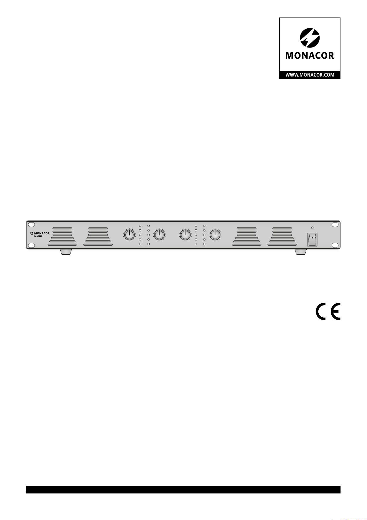
ELA-Class-D-Verstärker
mit 4 Kanälen
Class D PA Amplifier
with 4 Channels
PA-4120D
Bestell-Nr. • Order No. 1000015
BEDIENUNGSANLEITUNG
INSTRUCTION MANUAL
PROT
CH 1 CH 2 CH 3 CH 4
PEAK
SIG
100V
0 10 0 100 10 0 10
4Ω
PROT
PEAK
SIG
100V
4Ω
POWER
ELECTRONICS FOR SPECIALISTS ELECTRONICS FOR SPECIALISTS ELECTRONICS FOR SPECIALISTS ELECTRONICS FOR SPECIALISTS
Page 2
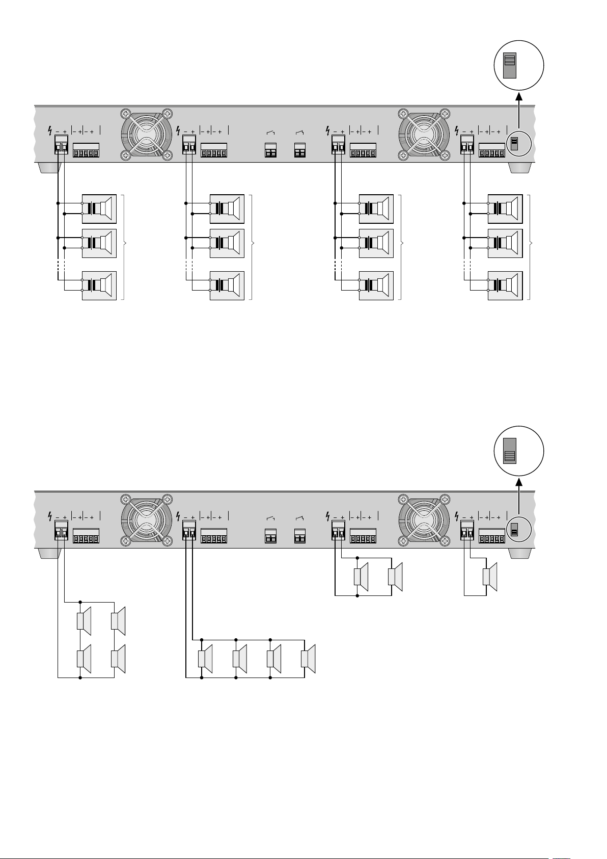
Anschluss von 100-V-Lautsprechern
4
Ω
4
Ω
➊
Connection of 100 V speakers
100 V
4 Ω
100V/4 Ω
100 V
100 V
100 V
CH 4
FAILED
INPUT
G
−
+
−
+
. . . . .
Nennbelastung
Rated load
120 W
−
+
100V/4 Ω
100 V
100 V
100 V
CH 3
FAILED
INPUT
G
STANDBY MUTE 100V/4 Ω
−
+
−
+
. . . . .
Nennbelastung
Rated load
120 W
−
+
100 V
100 V
100 V
CH 2
FAILED
INPUT
G
−
+
−
+
. . . . .
Nennbelastung
Rated load
120 W
−
+
100V/4 Ω
100 V
100 V
100 V
CH 1
FAILED
INPUT
G
100V
4Ω
−
+
−
+
. . . . .
Nennbelastung
Rated load
120 W
−
+
Anschlussbeispiel für niederohmige Lautsprecher
➋
Connection example for low-impedance speakers
CH 4
100V/4 Ω
FAILED
INPUT
G
4 Ω
4 Ω
+
Ω
4
-
+
Ω
4
-
+
-
+
-
Gesamtimpedanz der Lautsprechergruppe
Total impedance of the speaker group
CH 3
100V/4 Ω
FAILED
INPUT
+
-
Gesamtimpedanz der Lautsprechergruppe
Total impedance of the speaker group
100 V
4 Ω
G
STANDBY MUTE 100V/4 Ω
+
-
16 Ω
+
-
16 Ω
Gesamtimpedanz der Lautsprechergruppe
Total impedance of the speaker group
+
16 Ω 16 Ω
-
CH 2
FAILED
INPUT
G
+
-
8 Ω
4
+
8
Ω
-
Ω
CH 1
100V/4 Ω
FAILED
INPUT
G
+
4 Ω
-
Impedanz des Lautsprechers
Impedance of the speaker
4 Ω
100V
4Ω
2
Page 3

Deutsch ...........Seite 4
English ............Page 6
Deutsch
Nennausgangsleistung (Sinusleistung) 4 × 120 W
Klirrfaktor ≤ 0,1 % bei 1 kHz und 1/3 Nennausgangsleistung
Lautsprecherausgänge 100 V (Mindestlastimpedanz 83 Ω) oder 4 Ω
Eingänge (Empfindlichkeit / Impedanz; Anschluss) 0,775 V / 20 kΩ; Steckschraubklemmen, symmetrisch
Fehlermeldeausgänge im Fehlerfall: ⎓ 4,6 V; belastbar mit 50 mA
Frequenzbereich 80 – 16 000 Hz (+1 dB, −3 dB)
Signal-Rausch-Abstand ≥ 95 dB
Einsatztemperatur 0 – 40 °C
Stromversorgung 230 V / 50 Hz
Leistungsaufnahme max. 850 VA
Abmessungen 483 × 52 × 320 mm (B × H × T), 1 HE
Gewicht 5,1 kg
English
Rated output power (RMS power) 4 × 120 W
THD ≤ 0.1 % at 1 kHz and 1/3 rated output power
Speaker outputs 100 V (minimum load impedance: 83 Ω) or 4 Ω
Inputs (sensitivity / impedance; connection) 0.775 V / 20 kΩ; plug-in screw terminals, balanced
Fault indication outputs in case of a fault: ⎓ 4,6 V;
Frequency range 80 – 16 000 Hz (+1 dB, −3 dB)
S / N ratio ≥ 95 dB
Ambient temperature 0 – 40 °C
Power supply 230 V / 50 Hz
Power consumption 850 VA max.
Dimensions 483 × 52 × 320 mm (W × H × D), 1 RS
Weight 5.1 kg
Technische Daten
Specifications
can be loaded with
50 mA
ELECTRONICS FOR SPECIALISTS ELECTRONICS FOR SPECIALISTS ELECTRONICS FOR SPECIALISTS ELECTRONICS FOR SPECIALISTS
3
Page 4
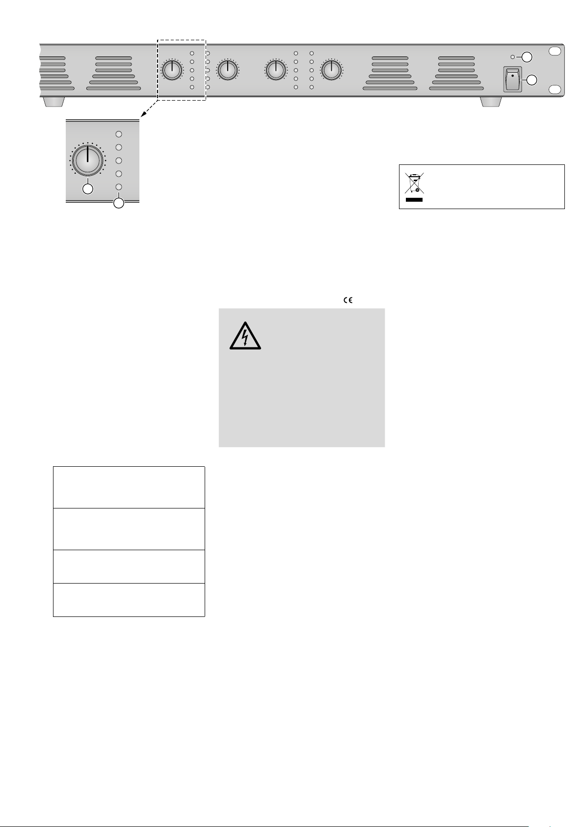
Vorderseite
➌
CH 1 CH 2 CH 3 CH 4
Deutsch
0 10 0 100 10 0 10
CH 1
0 10
3
PROT
PEAK
SIG
100 V
4 Ω
4
ELA-Class-D-Verstärker
mit 4Kanälen
Diese Anleitung richtet sich an den Installateur des Geräts mit Fachkenntnissen in
der 100-V-Beschallungstechnik. Bitte lesen
Sie die Anleitung vor dem Betrieb gründlich durchund heben Sie sie für ein späteres
Nachlesen auf.
1 Übersicht
1.1 Vorderseite
1 LED zur Anzeige, dass der Verstärker ein-
geschaltet oder auf Standby geschaltet ist
(☞ „Standby“ in Kap. 5)
2 Ein- /Ausschalter POWER
für jeden Kanal CH 1 bis CH 4:
3 Pegelregler
4 LED-Anzeigen
Die LED leuchtet, wenn die Schutzschaltung anspricht und für kurze Zeit
PROT
nach jedem Einschalten und Ausschalten (bzw. Schalten auf Standby*).
Die LED leuchtet, wenn der maximal
zulässige Signalpegel erreicht ist; bei
PEAK
permanentem Leuchten den Pegelregler zurückdrehen.
Die LED leuchtet ab einem bestimm-
SIG
ten Signalpegel (abhängig vom Pegelregler).
100 V
Die jeweils leuchtende LED zeigt den
oder
eingestellten Betriebsmodus an.
4 Ω
* über einen an den Klemmen STANDBY (7) ange-
schlossenen Schalter
1.2 Rückseite
5
Umschalter zum Einstellen des Betriebsmodus:
„100 V“ = Betrieb mit 100-V-Lautsprechern
„4 Ω“ = Betrieb mit niederohmigen Laut-
sprechern
6 Netzkabel zum Anschluss an 230 V / 50 Hz
7
Steckschraubklemmen STANDBY zum
Anschluss eines
„Einschalten Standby“; ist kein Schalter angeschlossen, müssen die Klemmen
gebrückt sein
Schalters
für die Funktion
PROT
PEAK
SIG
100V
4Ω
PROT
PEAK
SIG
100V
4Ω
8 Steckschraubklemmen MUTE
schluss eines Schalters zum Stummschalten
für jeden Kanal CH 1 bis CH 4:
9
Steckschraubklemmen „100 V/ 4 Ω“
Anschluss der Lautsprecher
10
Steckschraubklemmen FAILED, verwendbar als Fehler meldeausgang für die
überwachung: ☞
11
Steckschraubklemmen INPUT: symmetri-
Kap. 4.2.3
scher Eingang zum Anschluss einer MonoSignalquelle mit Line-Pegel
2 Sicherheitshinweise
Das Produkt entspricht allen relevanten Richtlinien der EU und trägt deshalb das -Zeichen.
WARNUNG
Im Betriebsmodus „100 V“ liegt an den Lautsprecheranschlüssen (9) berührungsgefährliche Spannung bis 100 V an. Führen Sie alle
Anschlüsse nur bei ausgeschaltetem Verstärker durch.
Verwenden Sie das Produkt nur im Innen-
•
bereich und schützen Sie es vor Tropf- und
Spritzwasser sowie vor hoher Luftfeuchtigkeit. Der zulässige Einsatztemperaturbereich
beträgt 0 – 40 °C.
Stellen Sie keine mit Flüssigkeit gefüllten
•
Gefäße, z. B. Trinkgläser, auf das Produkt.
Die im Produkt entstehende Wärme muss
•
durch Luftzirkulation abgegeben werden.
Decken Sie darum die Lüftungsöffnungen
am Gehäuse nicht ab.
Benutzen Sie das Produkt nicht und ziehen
•
Sie sofort den Netzstecker aus der Steckdose, wenn:
1.
sichtbare Schäden am Gerät oder am
Netz kabel vorhanden sind,
2.
nach einem Sturz oder Ähnlichem der
Verdacht auf einen Defekt besteht,
3. Funktionsstörungen auftreten.
Lassen Sie Schäden in jedem Fall in einer
Fachwerkstatt reparieren.
Ein beschädigtes Netzkabel darf nur durch
•
eine Fachwerkstatt ersetzt werden.
Ziehen Sie den Netzstecker nie am Kabel
•
aus der Steckdose, fassen Sie immer am
Stecker an!
Verwenden Sie zum Säubern nur ein tro-
•
ckenes weiches Tuch, niemals Chemikalien
oder Wasser.
Wird das Produkt falsch verwendet oder
•
nicht fachgerecht repariert, kann keine
Das Produkt wird mit lebensgefährlicher Netzspannung
versorgt. Nehmen Sie deshalb
niemals selbst Eingriffe daran
vor und stecken Sie nichts
durch die Lüftungsöffnungen!
Es besteht die Gefahr eines
elektrischen Schlages.
für den An-
für den
Fern-
1
POWER
2
Haftung für daraus resultierende Sach- oder
Personenschäden und keine Garantie für das
Produkt übernommen werden.
Soll das Produkt endgültig aus dem
Betrieb genommen werden, entsorgen Sie es gemäß den örtlichen Vorschriften.
3 Einsatzmöglichkeiten
Dieser Class-D-Verstärker ist speziell für ELAAnlagen konzipiert, die mit 100-V-Technik
arbeiten. Es ist jedoch auch möglich, anstelle
von 100-V-Lautsprechern, nieder ohmige Lautsprecher zu verwenden.
Über vier Verstärkerkanäle lässt sich für
vier Beschallungszonen die Lautstärke individuell anpassen. Jeder Kanal verfügt über einen
symmetrischen Line-Pegel-Eingang und einen
Fehlermeldeausgang zur Fernüberwachung
seines Betriebszustands (beide Anschlüsse als
Steckschraubklemmen). Es besteht außerdem
die Möglichkeit, zwei externe Schalter anzuschließen: einen Schalter zum Stummschalten
aller vier Kanäle sowie einen Schalter für die
Funktion „Einschalten Standby“.
4 Installation
Die Installation sollte nur durch eine qualifizierte Fachkraft vorgenommen werden.
4.1 Gerät aufstellen
Der Verstärker ist für den Einschub in ein Rack
(482 mm / 19”) vorgesehen, kann aber auch
als frei stehendes Gerät verwendet werden. In
jedem Fall muss Luft ungehindert durch alle
Lüftungsöffnungen strömen können, damit
eine ausreichende Kühlung gewährleistet ist.
4.1.1 Rackeinbau
Für die Rackmontage wird 1 HE (Höhen einheit
= 44,45 mm) benötigt. Für einen sicheren
Halt des Geräts im Rack wird die zusätzliche
Verwendung von Seitenschienen oder einer
Boden platte empfohlen.
Die vom Verstärker erwärmte Luft muss
aus dem Rack austreten können. Anderenfalls
kommt es im Rack zu einem Hitzestau, wodurch nicht nur der Verstärker, sondern auch
andere Geräte im Rack beschädigt werden können. Bei unzureichendem Wärmeabfluss in das
Rack eine Lüftereinheit einsetzen.
4.2
Gerät einstellen und anschließen
Alle Anschlüsse dürfen nur bei ausgeschaltetem Verstärker durchgeführt werden!
Der Verstärker ist mit Schraubklemmen ausgerüstet, die sich zum Herstellen der Anschlüsse
vom Gerät abziehen und danach wieder aufstecken lassen.
4
Page 5
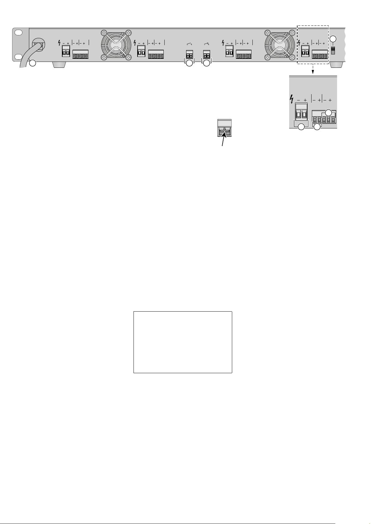
Rückseite
➍
CH 4
100V/4 Ω
FAILED
INPUT
G
230V~/50 Hz
6
4.2.1 Betriebsmodus einstellen und
Lautsprecher anschließen
Es lassen sich entweder 100-V-Lautsprecher
oder niederohmige Lautsprecher anschließen.
Die beiden Lautsprechertypen dürfen nicht gemischt angeschlossen werden!
Die Stellung des Schiebeschalters (5) bestimmt den Betriebsmodus für alle Kanäle. Den
Schalter je nach Lautsprechertyp einstellen und
für jeden Kanal die Lautsprecher an die Klemmen „100V/ 4 Ω“ (9) anschließen:
A 100-V-Lautsprecher:
Den Schalter in die Position „100 V“ stellen. Die Summe der von den Lautsprechern
aufgenommenen Leistungen darf die Nennleistung des Verstärkers nicht überschreiten, d. h. die Gesamtbelastung pro Kanal
darf maximal 120 W betragen. Es ist jedoch
anzuraten, sie um 10 – 20 % unter diesem
Grenzwert zu halten, um zu vermeiden,
dass der Verstärker permanent unter Volllast
betrieben wird. Die Abb.1 auf Seite2 zeigt
den Anschluss von 100-V-Lautsprechern.
B Niederohmige Lautsprecher
Den Schalter in die Position„4 Ω“ stellen.
Pro Kanal muss die Gesamtimpedanz der
Lautsprecher mindestens 4 Ω betragen. Die
Abb.2 auf Seite 2 zeigt verschiedene Arten,
die Mindestimpedanz von 4 Ω einzuhalten.
Es gibt aber noch weitere Möglichkeiten.
Achtung: Achten Sie darauf, den Schalter nicht versehentlich zu verstellen. Bei falscher Stellung können die Lautsprecher und der Verstärker beschädigt
werden.
4.2.2 Signalquellen anschließen
An jeden Kanal lässt sich über die Klemmen
INPUT (11) eine Mono-Signalquelle mit LineSignalpegel (z. B. Vor verstärker) anschließen. Die Signalquellen sollten symmetrisch
angeschlossen werden, da symmetrische
Signalübertragung eine bessere Störunterdrückung bietet. Ist der Ausgang einer Quelle
asymmetrisch (z. B. bei einer Cinch-Buchse),
die Klemmen„−“ und „G“ des jeweiligen Eingangs miteinander verbinden. Den Signal-Leiter an die Klemme „+“ des Eingangs anschließen und den Masse-Leiter an die Klemme „G“.
4.2.3 Fehlermeldeausgang
Für die Fernüberwachung bietet jeder Kanal
einen Fehlermeldeausgang über die Klemmen
FAILED (10). Bei Ansprechen der Schutzschaltung für einen Kanal liegt am entsprechenden Ausgang FAILED eine Gleichspannung
von 4,6 V an. Der Ausgang ist mit max. 50 mA
belastbar. Hier kann ein Signalgeber angeschlossen werden, der den Fehler optisch oder
akustisch meldet.
4.2.4 Externe Schalter anschließen
Um den Verstärker stummzuschalten, lässt
sich ein Schalter (Schließer) an die Klemmen
MUTE(8) anschließen.
CH 3
100V/4 Ω
FAILED
INPUT
G
STANDBY MUTE 100V/4 Ω
8
7
An die Klemmen STANDBY (7) lässt sich ein
Schalter anschließen, mit dem sich der Verstärker einschalten (Schalter geschlossen) und
in den Standby-Betrieb (Schalter geöffnet)
schalten lässt.
Hinweis: Wird an den Klemmen STANDBY
kein Schalter angeschlossen, müssen sie
über eine Drahtbrücke miteinander verbunden sein (☞ Abb. 5). Anderenfalls
lässt sich der Verstärker nicht mit dem
Netzschalter(2) einschalten.
➎
4.2.5 Stromversorgung
Den Stecker des Netzkabels (6) in eine Steckdose (230 V / 50 Hz) stecken.
5 Bedienung
Um Schaltgeräusche zu vermeiden, die Signalquellen vor dem Verstärker einschalten. Nach
dem Betrieb den Verstärker als erstes Gerät
wieder ausschalten.
1) Um beim ersten Einschalten eine zu hohe
Anfangslautstärke zu vermeiden, die Pegelregler (3) aller vier Kanäle auf null drehen.
2)
Den Verstärker mit dem Netzschalter
POWER (2) einschalten. Die LED (1) über
dem Schalter leuchtet und in der LEDReihe(4) jedes Kanals zeigt die entsprechende LED („100 V“ oder „4 Ω“) den Betriebsmodus an. Für kurze Zeit nach dem
Einschalten leuchtet für jeden Kanal die LED
PROT und der Verstärker ist stummgeschaltet (Einschaltverzögerung).
Standby: Leuchtet nach dem Betätigen des
Schalters POWER nur die darüberliegende LED,
befindet sich der Verstärker im Standby-Betrieb.
−
Ist an den Klemmen STANDBY (7) ein Schalter
angeschlossen, lässt sich der Verstärker mit
diesem einschalten.
− Ist kein Schalter an den Klemmen STANDBY
angeschlossen, müssen die Klemmen gebrückt sein (☞ Hinweis in Kap. 4.2.4), sonst
lässt sich der Verstärker nicht einschalten.
3) An jedem Kanal das Signal der angeschlossenen Quelle auf den Eingang geben und
mit dem Pegelregler die Lautstärke für die
jeweilige Beschallungszone einstellen. In der
LED-Reihe leuchtet die LED SIG ab einem
bestimmten Signalpegel auf (jehöher der
Pegel, desto heller die LED). Die LED PEAK
leuchtet, wenn der integrierte Limiter den
Pegel begrenzt, weil der maximal zulässige
Wert erreicht wurde. Die LED PEAK sollte
höchstens kurz bei den lautesten Passagen
aufleuchten. Leuchtet sie länger, den Pegelregler entsprechend zurückdrehen.
Wird ein Kanal nicht verwendet, seinen
Regler auf null drehen.
4) Ist ein Schalter an den Klemmen MUTE (8)
angeschlossen, lässt sich mit ihm der Ton
für alle Kanäle aus- und wieder einschalten.
CH 2
FAILED
INPUT
G
100V/4 Ω
100 V/4Ω
9
CH 1
FAILED
CH 1
FAILED
10
INPUT
G
INPUT
11
5
G
5) Ist ein Schalter an den Klemmen STANDBY
angeschlossen, lässt sich der Verstärker mit
ihm auf Standby schalten. Zum Ausschalten
des Verstärkers den Netzschalter POWER
betätigen, die LED darüber erlischt
Nach dem Ausschalten (bzw. Wechsel
auf Standby über einen angeschlossenen
Schalter) leuchtet kurz an jedem Kanal die
LED PROT auf.
5.1
Ansprechen einer Schutzschaltung
Jeder Verstärkerkanal ist mit einer Schutzschaltung gegen Überhitzung, Überlastung
und Kurzschluss am Lautsprecherausgang
ausgestattet. Spricht die Schutzschaltung für
einen Kanal an, leuchtet in der LED-Reihe (4)
des Kanals die oberste LED PROT. Zusätzlich
wird der Fehler über ein am entsprechenden
Ausgang FAILED (10) angeschlossenes Gerät
gemeldet (☞ Kap. 4.2.3).
1. Bei einer Überhitzung den Verstärker nicht
ausschalten, sondern den jeweiligen Pegelregler (3) auf null drehen, damit die Endstufe entlastet ist und weiterhin durch den
jeweiligen Lüfter gekühlt wird. Bei schlechter Belüftung am Einsatz ort für eine bessere
Luftzirkulation sorgen. Wird das Gerät nach
dem Abkühlen wieder normal betrieben und
die Schutzschaltung spricht erneut an, liegt
möglicherweise eine Überlastung vor (siehe
Punkt 2).
2. Bei einer Überlastung im Betriebsmodus
„100 V“ weniger Lautsprecher anschließen
oder, wenn möglich, an den Lautsprechern
eine geringere Leistungsaufnahme ein stellen.
3. Bei einem Kurzschluss diesen lokalisieren
und beseitigen.
Änderungen an den Anschlüssen dürfen nur
bei ausgeschaltetem Verstärker vorgenommen
werden! Lässt sich der Fehler nicht beheben,
das Gerät zur Reparatur in eine Fachwerkstatt
geben.
Technische Daten Seite 3
Änderungen vorbehalten.
Diese Bedienungsanleitung ist urheberrechtlich
für MONACOR ® INTERNATIONAL GmbH & Co. KG
geschützt. Eine Reproduktion für eigene kommerzielle
Zwecke – auch auszugsweise – ist untersagt.
100V
4Ω
Deutsch
5
Page 6
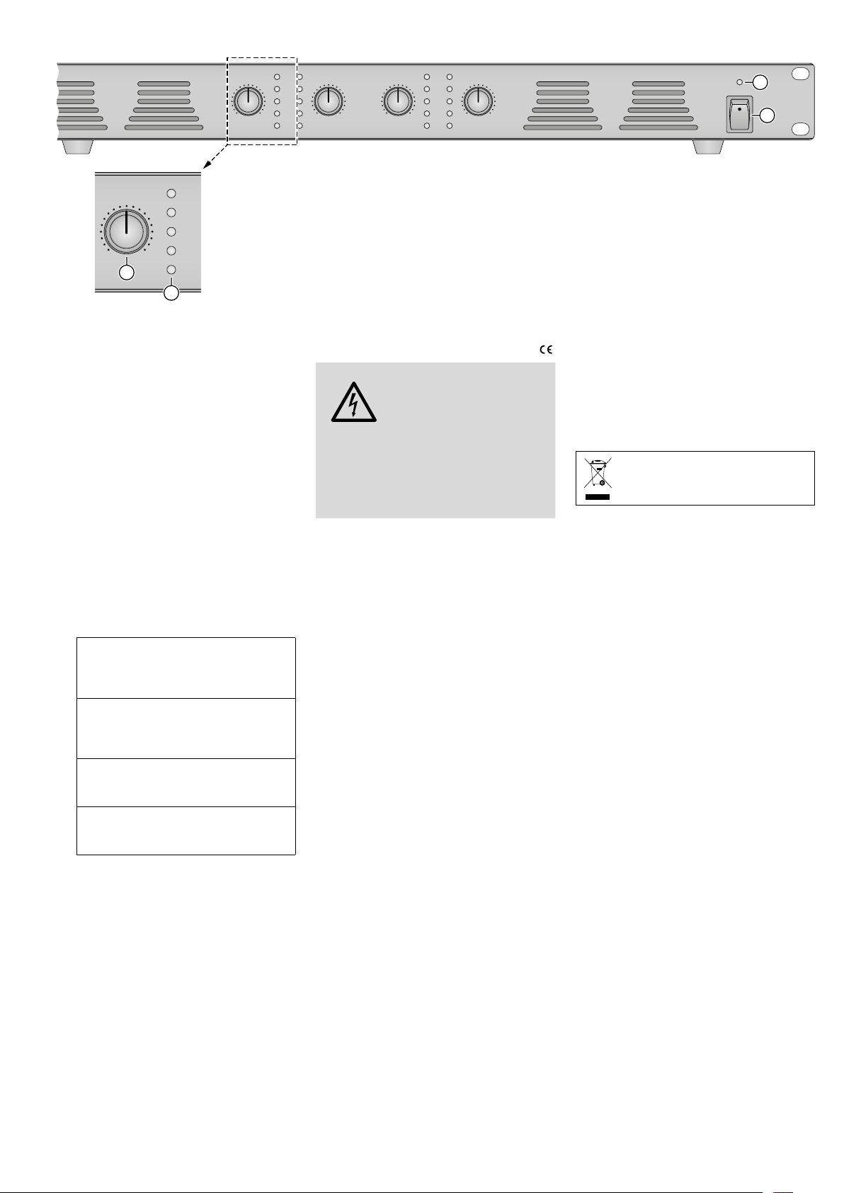
Front panel
➌
English
CH 1 CH 2 CH 3 CH 4
0 10 0 100 10 0 10
CH 1
0 10
3
PROT
PEAK
SIG
100 V
4 Ω
4
Class D PA Amplifier
with4Channels
These instructions are intended for installers
of the unit with technical knowledge of 100 V
technology in PA applications. Please read the
operating instructions carefully prior to operation and keep them for later reference.
1 Overview
1.1 Front panel
1
LED indicator; to indicate that the amplifier
has been switched on or switched to the
standby mode (☞ “Standby” in chapter 5)
2 POWER switch
for each channel CH 1 to CH 4:
3 Level control
4 LED indicators
Will light up when the protective circuit
responds; it will light up briefly each
PROT
time the amplifier is switched on or off
(or switched to the standby mode*).
Will light up when the maximum signal
level allowed has been reached; if the
PEAK
LED indicator lights up continuously,
turn back the level control.
Will light up when a specific signal level
SIG
has been reached (depending on the
level control).
100 V
The operating mode set will be in-
or
dicated by the LED indicator that
4 Ω
lightsup.
* via a switch connected to the terminals STANDBY (7)
1.2 Rear panel
5 Switch to set the operating mode:
“100 V” = operation with 100 V speakers
“4 Ω” = operation with low-impedance
speakers
6
Power cable for connection to 230 V/ 50 Hz
7 Plug-in screw terminals STANDBY to con-
nect a switch for the function “Switch on
Standby”; if no switch is connected,
make sure that the terminals are bridged
8 Plug-in screw terminals MUTE to connect
a switch for muting the amplifier
for each channel CH 1 to CH 4:
9
Plug-in screw terminals “100 V/ 4 Ω” to
connect the speakers
PROT
PEAK
SIG
100V
4Ω
10
Plug-in screw terminals FAILED; can be
PROT
PEAK
SIG
100V
4Ω
used as a fault indication output for
remote monitoring: ☞ chapter 4.2.3
11
Plug-in screw terminals INPUT: balanced
input to connect a mono signal source with
line level
2 Safety Notes
The product corresponds to all relevant directives of the EU and is therefore marked with .
WARNING
In the operating mode “100 V”, there is a
hazard of contact with a dangerous voltage
of up to 100 V at the speaker terminals (9).
Always switch off the amplifier before making
or changing any connections.
The product is suitable for indoor use only.
•
Protect it against dripping water, splash
water, high air humidity and heat. The
admissible ambient temperature range is
0 – 40 °C.
Do not place any vessel filled with liquid on
•
the product, e. g. a drinking glass.
The heat generated inside the product must
•
be dissipated by air circulation; never cover
the air vents of the housing.
Do not use the product and immediately
•
disconnect it from the mains socket
1.
if the unit or the mains cable is visibly
damaged
2. if a defect might have occurred after the
unit was dropped or suffered a similar
accident,
3. if malfunctions occur.
Any repairs must be made by skilled personnel only.
A damaged mains cable must be replaced
•
by skilled personnel only.
Never pull the mains cable to disconnect the
•
mains plug from the mains socket, always
seize the plug.
For cleaning only use a dry, soft cloth; never
•
use water or chemicals.
No guarantee claims for the product and no
•
liability for any resulting personal damage
or material damage will be accepted if the
product is not correctly used or if it is not
repaired in an expert way.
Important for UK Customers!
•
The wires in this mains lead are coloured in
accordance with the following code:
green / yellow = earth
blue = neutral
brown = live
The product uses dangerous
mains voltage. Leave servicing
to skilled personnel only and
never insert anything into the
air vents. Risk of electric shock!
1
POWER
2
As the colours of the wires in the mains lead
of this appliance may not correspond with
the coloured markings identifying the terminals in your plug, proceed as follows:
1.
The wire which is coloured green and yellow must be connected to the terminal in
the plug which is marked with the letter
E or by the earth symbol ⏚, or coloured
green or green and yellow.
2.
The wire which is coloured blue must
be connected to the terminal which is
marked with the letter N or coloured
black.
3. The wire which is coloured brown must
be connected to the terminal which is
marked with the letter L or coloured red.
Warning – This appliance must be earthed.
If the product is to be put out of operation definitively, dispose of the product according to local regulations.
3 Applications
This class D amplifier is specially designed for
PA systems that use 100 V technology. However, it is also possible to use low-impedance
speakers instead of 100 V speakers.
Via four amplifier channels, the volume
for up to four speaker zones can be separately
adjusted. Each channel provides a balanced
line level input and an error message output
for remote monitoring of the operation state
of the channel (both connections designed as
plug-in screw terminals). In addition, two external switches can be connected: a switch to
mute all four channels at the same time and a
switch for the function “Switch on Standby”.
4 Installation
Installation must be made by skilled personnel
only.
4.1 Setting up the amplifier
The amplifier is designed for insertion into a
rack (482 mm / 19"), but it can also be set up on
its own. In order to ensure sufficient cooling of
the amplifier, air must always be able to flow
freely through all air vents.
4.1.1 Rack installation
For rack installation, 1 rack space (1 RS =
44.45 mm) is required. For a safe installation
of the amplifier, lateral rails or a bottom plate
are recommended.
The hot air given off by the amplifier must
be dissipated from the rack; otherwise, heat
will accumulate in the rack which may not only
damage the amplifier but also other units in
the rack. In case of insufficient heat dissipation,
install a ventilation unit into the rack.
6
Page 7

Rear panel
➍
CH 4
100V/4 Ω
FAILED
INPUT
G
230V~/50 Hz
6
4.2 Adjusting and connecting
theamplifier
Always switch off the amplifier before making
any connections!
The amplifier is equipped with screw terminals;
to facilitate handling, it is possible to remove
the screw terminals from their plug-in connections on the amplifier and to reinsert them
after connection.
4.2.1 Setting the operating mode and
connecting the speakers
Either 100 V speakers or low-impedance
speakers can be connected. Never connect a
combination of these speaker types!
The position of the sliding switch (5) determines the operating mode of all channels.
Set the switch according to the speaker type
and then connect the speakers to the terminals
“100V/ 4 Ω” (9) for each channel.
A 100 V speakers:
Set the switch to the position “100 V”.
The total load of the speakers must not
exceed the rated load of the amplifier, i. e.
the maximum total load for each channel is
120 W. However, a total load of 10 – 20 %
beneath this maximum value is recommended to make sure that the amplifier
is not constantly operated under full load.
Fig.1 on page 2 shows the connection of
100 V speakers.
B Low-impedance speakers:
Set the switch to the position “4 Ω”. The
minimum total impedance of the speakers
is 4 Ω for each channel. Fig.2 on page2
shows various options of how to keep the
minimum impedance of 4 Ω. However, there
are more possibilities.
Attention: Make sure that the position of the switch
is never changed by accident. A wrong setting may
damage the speakers and the amplifier.
4.2.2 Connecting signal sources
Via the terminals INPUT (11), a mono signal
source with line level (e. g. preamplifier) can
be connected to each channel. Balanced signal
transmission will improve interference suppression; therefore, the signal sources connected
should be balanced. If the output of a source
is unbalanced (e. g. for an RCA jack), connect
the terminals “−“ and “G” of the corresponding input with each other. Connect the signal
conductor to the terminal “+” of the input and
the ground conductor to the terminal “G”.
4.2.3 Fault indication output
For remote monitoring, each channel provides a fault indication output via the terminals FAILED (10). When the protective circuit
responds for a channel, a DC voltage of 4.6 V
will be available at the corresponding output
FAILED. The maximum load of the output is
50 mA. A unit for optical or acoustic fault reporting can be connected to the output.
CH 3
100V/4 Ω
FAILED
INPUT
G
STANDBY MUTE 100V/4 Ω
8
7
4.2.4 Connecting external switches
To mute the amplifier, a switch (NO switch)
can be connected to the terminals MUTE (8).
The terminals STANDBY (7) can be used
to connect a switch that allows you to switch
the amplifier on (switch closed) or to go to the
standby mode (switch open).
Note: If no switch is connected to the ter-
minals STANDBY, make sure that the terminals are bridged via a jumper (☞fig.5).
Otherwise, it will not be possible to switch
on the amplifier by means of the POWER
switch (2).
➎
4.2.5 Power supply
Connect the plug of the mains cable (6) to a
mains socket (230 V/ 50 Hz).
5 Operation
To avoid switching noise, first switch on the signal sources before switching on the amplifier.
After operation, switch off the amplifier first.
1)
Before switching on the amplifier for the
first time, set the level controls (3) of all four
channels to zero to make sure that the initial
volume will not be too high.
2) Use the POWER switch (2) to switch on the
amplifier. The LED indicator (1) above the
switch will light up; in the LED indicator
strip (4) of each channel, the LED indicator “100 V” or “4 Ω” will indicate the
operating mode. After switch-on, the LED
indicator PROT for each channel will light
up briefly and the amplifier will be muted
(switch-on delay).
Standby: The amplifier is in the standby mode,
if only the LED indicator above the POWER
switch lights up after the switch has been
pressed.
− If a switch has been connected to the termi-
nals STANDBY (7), the switch can be used to
switch on the amplifier.
−
If no switch is connected to the terminals
STANDBY, make sure that the terminals are
bridged (☞ note in chapter 4.2.4); otherwise, it will not be possible to switch on the
amplifier.
3)
At each channel, feed the signal of the
source connected to the input and then use
the level control to adjust the volume for the
corresponding speaker zone. In the LED indicator strip, the LED indicator SIG will light
up when a specific signal level has been
reached (the higher the level, the brighter
the LED indicator). The LED indicator PEAK
will light up when the level is limited by the
integrated limiter because the maximum
value admissible has been reached. The LED
indicator PEAK should only light up briefly
for signal peaks. If the LED indicator lights
up for a longer time, turn back the level
control accordingly.
If a channel is not used, turn the corre-
sponding control to zero.
CH 2
FAILED
INPUT
G
4)
If a switch is connected to the terminals
100V/4 Ω
100 V/4Ω
9
CH 1
FAILED
CH 1
FAILED
10
INPUT
G
INPUT
11
5
G
MUTE (8), it can be used to mute and
unmute the sound for all channels.
5)
If a switch is connected to the terminals
STANDBY, it can be used to switch the
amplifier to the standby mode. To switch off
the amplifier, use the POWER switch; the
LED indicator above the switch will go out.
After the amplifier has been switched
off (or switched to the standby mode via a
switch connected), the LED indicator PROT
lights up briefly at each channel.
5.1 Protective-circuit response
Each amplifier channel is equipped with a protective circuit against overheating, overload
and short circuit at the speaker output. When
the protective circuit responds for a channel,
the upper LED indicator PROT in the LED indicator strip (4) for the corresponding channel will
light up. In addition, the fault is reported via
a unit connected to the corresponding output
FAILED (10) (☞ chapter 4.2.3).
1. In case of overheating, do not switch off the
amplifier, but set the corresponding level
control (3) to zero. This will reduce the load
on the power amplifier and the corresponding fan will still cool it. If cooling at the place
of operation is insufficient, improve the air
circulation. If the protective circuit responds
again after the amplifier has cooled down
and is operated normally again, the amplifier
may be overloaded (see item 2).
2. In case of overload in the operating mode
“100 V”, reduce the number of speakers
connected or, if possible, reduce the power
consumption by the speakers.
3. In case of a short circuit, locate and eliminate
the short circuit.
Always switch off the amplifier before making
any changes to the connections! If it is not possible to eliminate the fault, take the amplifier
to skilled personnel.
Specifications page 3
Subject to technical modification.
All rights reserved by MONACOR ® INTERNATIONAL
GmbH & Co. KG. No part of this instruction manual
may be reproduced in any form or by any means for
any commercial use.
100V
4Ω
English
7
Page 8

MONACOR INTERNATIONAL GmbH & Co. KG • Zum Falsch 36 • 28307 Bremen • Germany
Copyright© by MONACOR INTERNATIONAL. All rights reserved.
A-2053.99.01.03.2020
 Loading...