

Page 1
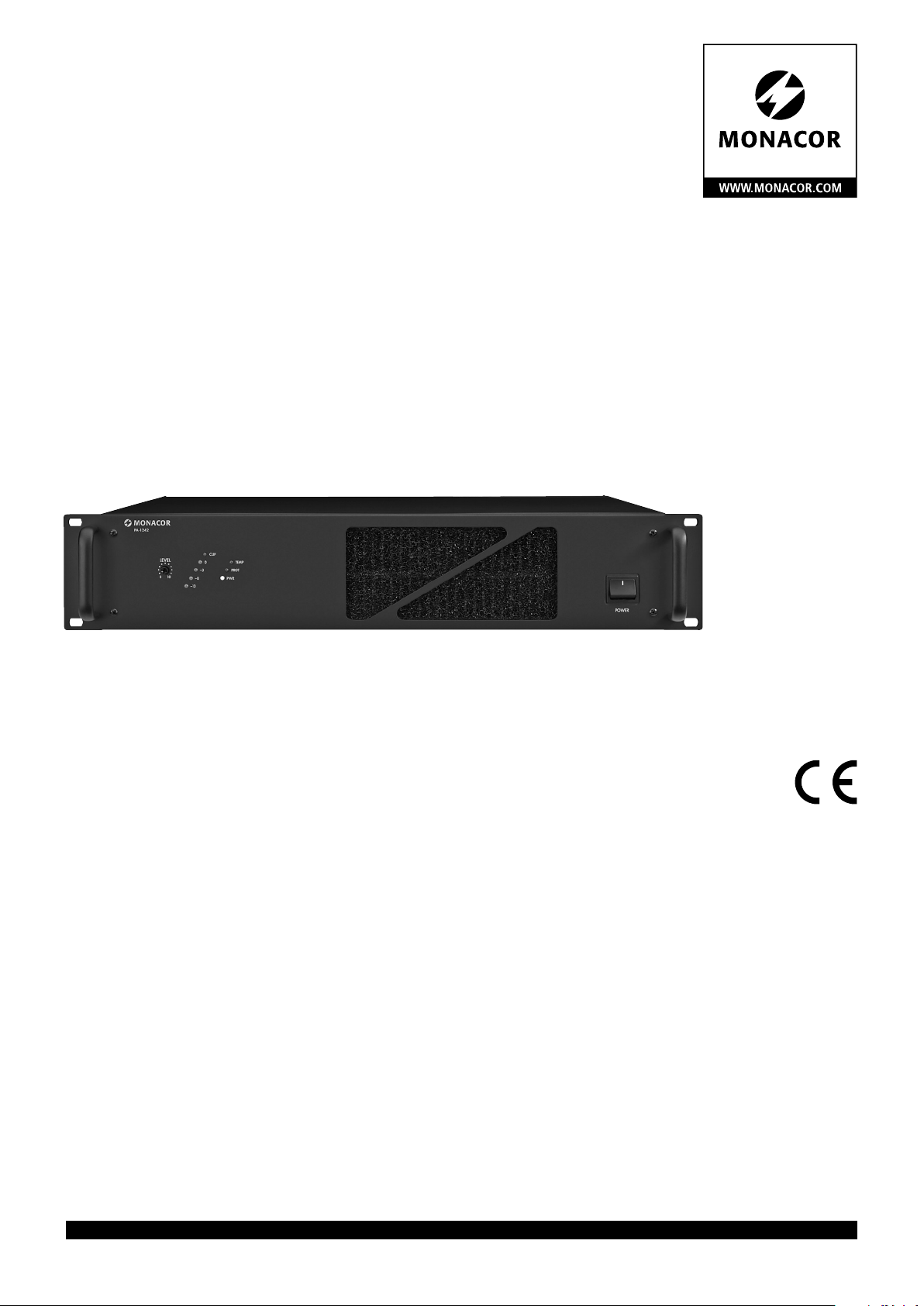
ELA-Leistungsverstärker
PA Power Amplifier
PA-1242
Bestell-Nr. • Order No. 17.2780
BEDIENUNGSANLEITUNG
INSTRUCTION MANUAL
MODE D’EMPLOI
ISTRUZIONI PER L’USO
MANUAL DE INSTRUCCIONES
INSTRUKCJA OBSŁUGI
VEILIGHEIDSVOORSCHRIFTEN
SIKKERHEDSOPLYSNINGER
SÄKERHETSFÖRESKRIFTER
TURVALLISUUDESTA
PA-1480
Bestell-Nr. • Order No. 17.1110
ELECTRONICS FOR SPECIALISTS ELECTRONICS FOR SPECIALISTS ELECTRONICS FOR SPECIALISTS ELECTRONICS FOR SPECIALISTS
Page 2

Deutsch ...........Seite 4
English ............Page 6
Français ...........Page 8
Italiano............Pagina 10
Español ...........Página 12
Polski .............Strona 14
Nederlands ........Pagina 16
Dansk .............Sida 16
Svenska ...........Sidan 17
Suomi.............Sivulta 17
ELECTRONICS FOR SPECIALISTS ELECTRONICS FOR SPECIALISTS ELECTRONICS FOR SPECIALISTS ELECTRONICS FOR SPECIALISTS
2
Page 3
PA-1242
70 V
100 V
COM
xx Ω 8 Ω xx Ω xx Ω
LEVEL
0 10
CLIP
0
TEMP
–3
PROT
–8
PWR
–13
POWER
1 2 3 4 5 6
24V /20 A
230V~/50 Hz
COM
2.6Ω 8Ω 20Ω 42Ω
SPEAKER OUTPUTS
INPUT LINK
400Hz
ON
MONITOR
100V70V44V25V
OFF
INPUT LINK
GND
BALANCED INPUTS +4dBu/1.23 V 30kΩ
7 8 9 10 11 12 13 14 15 16
MONITOR
100V70Vxx V25V
COM
xx Ω 8 Ω xx Ω xx Ω
MONITOR
100V70Vxx V25V
➀
➁
COM
8 Ω
xx Ω 8 Ω xx Ω xx Ω
100V70Vxx V25V
MONITOR
➂ ➃
+
100 V
-
max. Belastung
max. load
RMS
240 W
480 W
– PA-1242
RMS
– PA-1480
100 V
+
-
. . . . .
+
100 V
-
8 Ω
MONITOR
COM
xx Ω 8 Ω xx Ω xx Ω
100V70Vxx V25V
➄ ➅
+
8 Ω
-
+
70 V
-
max. Belastung
max. load
RMS
240 W
480 W
– PA-1242
RMS
– PA-1480
70 V
+
-
. . . . .
+
70 V
-
+
-
16 Ω
+
16 Ω
-
COM
xx Ω 8 Ω xx Ω xx Ω
8 Ω
MONITOR
100V70Vxx V25V
COM
8 Ω
xx Ω 8 Ω xx Ω xx Ω
100V70Vxx V25V
MONITOR
➆ ➇
+
4 Ω
-
+
4 Ω
-
3
+
8 Ω
-
+
8 Ω 8 Ω
-
+
8 Ω
-
+
-
Page 4
ELA-Leistungsverstärker
Bitte lesen Sie diese Anleitung vor dem
Betrieb gründlich durch und heben Sie sie für
Deutsch
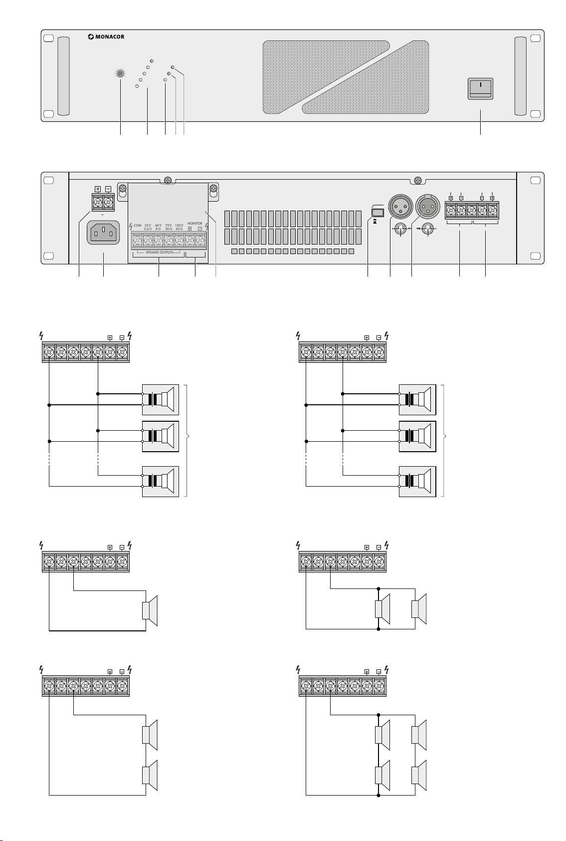
ein späteres Nachlesen auf. Auf der ausklappbaren Seite 3 finden Sie alle beschriebenen
Bedienelemente und Anschlüsse.
Die Lautsprecher dürfen nur von Personen, die ausreichende Fachkenntnisse in der
100-V-Beschallungstechnik besitzen, angeschlossen werden (Kap. 4.1). Die Bedienung
des Verstärkers ist einfach und auf erwachsene Nichtfachleute ausgerichtet. Treten jedoch Fragen auf, wenden Sie sich bitte an
Ihren Installateur oder Fachhändler.
1 Übersicht der Anschlüsse
und Bedienelemente
1.1 Frontseite
1 Pegelregler
2
Pegelanzeige, bei Übersteuerung leuchtet
die rote Anzeige CLIP
3 Betriebsanzeige PWR
4
Anzeige PROT leuchtet bei aktivierter
Schutzschaltung:
1. ca. 1 Sekunde lang nach dem Einschalten (Einschaltverzögerung)
2. ca. 1 Sekunde lang nach dem Ausschalten
3. wenn der Verstärker überlastet ist
4. wenn der Verstärker überhitzt ist
5
Überhitzungsanzeige TEMP leuchtet,
wenn die Kühlkörpertemperatur 100 °C
erreicht. Der Verstärker wird dann stummgeschaltet. Zusätzlich leuchtet die rote
Anzeige PROT (4).
6 Ein- /Ausschalter POWER
Hinweis: Liegt eine 24-V-Spannung von
einer Notstromeinheit am Anschluss DC
POWER (7) an, lässt sich der Verstärker
nicht ausschalten.
1.2 Rückseite
7 Schraubanschlüsse für eine Notstromver-
sorgung (24 V⎓)
8
Buchse für das beiliegende Netzkabel zum
Anschluss an 230 V/ 50 Hz
9 Lautsprecheranschlüsse
10
Anschluss für 100-V-Monitorlautsprecher
zu Kontrollzwecken
Wichtig! Diese Klemmen sind mit denen
für 100-V-Lautsprecher (COM und 100 V)
parallelgeschaltet. Den Verstärker nicht
überlasten. Die Belastung durch einen
Monitorlautsprecher muss zu der Belastung durch die übrigen Hauptlautsprecher
addiert werden, um so die Gesamtbelastung zu errechnen.
11
Schutzabdeckung für die Lautsprecher
anschlüsse
WARNUNG
12
Ein- /Ausschalter 400 Hz für den Hochpass
(senkt die Bässe ab)
Den Verstärker nie ohne
die Abdeckung betreiben.
Anderenfalls besteht bei
Berührung der Anschlüsse
die Gefahr eines elektrischen Schlags.
13
Signaleingang über die symmetrische
XLR-Buchse; Empfindlichkeit für Vollaussteuerung +4 dBu (1,2 V)
14
Durchschleifausgang über die XLR-Buchse
zum Anschluss eines weiteren ELA-Verstärkers
15
symmetrischer Signaleingang über
Schraubanschlüsse; Empfindlichkeit für
Vollaussteuerung +4 dBu (1,2 V)
16
Durchschleifausgang über Schraubanschlüsse zum Anschluss eines weiteren
ELA-Verstärkers
2 Hinweise
für den sicheren Gebrauch
Das Gerät entspricht allen relevanten Richtlinien der EU und trägt deshalb das -Zeichen.
WARNUNG
am Gerät vor und stecken Sie nichts durch
die Lüftungs öffnungen! Es besteht die Gefahr eines elektrischen Schlages.
Im Betrieb liegt an den Lautsprecheranschlüssen (9, 10) berührungsgefährliche
Spannung bis 100 V an. Den Verstärker nie
ohne die Schutzabdeckung (11) betreiben.
Alle Anschlüsse nur bei ausgeschalteter
ELA-Anlage vornehmen bzw. verändern.
Das Gerät ist nur zur Verwendung in In-
•
nenräumen geeignet. Schützen Sie es vor
Tropf- und Spritzwasser, hoher Luftfeuchtigkeit und Hitze (zulässiger Einsatztemperaturbereich 0 – 40 °C).
Stellen Sie keine mit Flüssigkeit gefüllten
•
Gefäße, z. B. Trinkgläser, auf das Gerät.
Die im Gerät entstehende Wärme muss
•
durch Luftzirkulation abgegeben werden.
Decken Sie die Lüftungsöffnungen nicht ab.
Ziehen Sie sofort den Netzstecker aus der
•
Steckdose:
1. wenn sichtbare Schäden am Gerät oder
am Netzkabel vorhanden sind,
2. wenn nach einem Sturz oder Ähnlichem
der Verdacht auf einen Defekt besteht,
3. wenn Funktionsstörungen auftreten.
Lassen Sie das Gerät in jedem Fall in einer
Fachwerkstatt reparieren.
Ziehen Sie den Netzstecker nie am Kabel
•
aus der Steckdose, fassen Sie immer am
Stecker an.
Verwenden Sie zum Reinigen nur ein tro-
•
ckenes, weiches Tuch, niemals Wasser oder
Chemikalien.
Wird das Gerät zweckentfremdet, nicht
•
richtig angeschlossen, falsch bedient oder
nicht fachgerecht repariert, kann keine
Garantie für das Gerät und keine Haftung
für daraus resultierende Sach- oder Personenschäden übernommen werden.
Das Gerät wird mit lebensgefährlicher Netzspannung
versorgt. Nehmen Sie deshalb niemals selbst Eingriffe
Soll das Gerät endgültig aus dem
Betrieb genommen werden, übergeben Sie es zur umweltgerechten
Entsorgung einem örtlichen Recyclingbetrieb.
3 Aufstellmöglichkeiten
Der Verstärker ist für den Einschub in ein
Rack (482 mm /19”) vorgesehen, kann aber
auch als Tischgerät verwendet werden. In
jedem Fall muss Luft ungehindert durch alle
Lüftungsöffnungen strömen können, damit
eine ausreichende Kühlung der Endstufen
gewährleistet ist.
3.1 Rackeinbau
Für die Rackmontage werden 2 HE (2 Höheneinheiten = 89 mm) benötigt. Damit das Rack
nicht kopflastig wird, muss der Verstärker im
unteren Bereich des Racks eingeschoben werden. Für eine sichere Befestigung reicht die
Frontplatte allein nicht aus. Zusätz lich muss
der Verstärker über die rückseitigen Befestigungslaschen mit dem Rack verschraubt
werden.
Die vom Verstärker ausgeblasene, erhitzte
Luft muss aus dem Rack nach hinten oder
oben austreten können. Anderenfalls kommt
es im Rack zu einem Hitzestau, wodurch nicht
nur der Verstärker, sondern auch weitere Geräte beschädigt werden können. Bei unzureichendem Wärmeabfluss in das Rack über
dem Verstärker eine Lüftereinheit einsetzen.
4 Verstärker anschließen
Alle Anschlüsse sollten nur durch eine qualifizierte Fachkraft und unbedingt bei ausgeschaltetem Verstärker vorgenommen werden!
4.1 Lautsprecher
Die Anschlüsse für die Lautsprecher befinden
sich unter der Schutzabdeckung (11). Zum
Anschließen die Abdeckung abschrauben.
WARNUNG
anschlüssen (9, 10) gefährliche Spannungen
bis 100 V an. Nach dem Anschließen die
Abdeckung wieder festschrauben, damit
die Kontakte vor Berührung geschützt sind.
Es können ELA-Lautsprecher (Abb. 3 und 4)
oder 8-Ω-Lautsprecher bzw. Lautsprechergruppen mit einer Gesamtimpedanz von
mindestens 8 Ω (Abb. 5 – 8) angeschlossen
werden.
4.1.1 ELA- und Monitorlautsprecher
Vorsicht! Bei ELA-Lautsprechern (Abb. 3
Die Lautsprecher an die entsprechenden Lautsprecherklemmen (9) an schließen. Dabei auf
die richtige Polarität achten (Plus- und Minusanschlüsse, wie in Abb. 3 und 4 dargestellt).
Der Verstärker darf nicht ohne
die Schutzabdeckung (11) betrieben werden. Im Betrieb
liegen an den Lautsprecher-
und4) darf die Gesamtbelastung
durch die Lautsprecher nicht mehr
als
240 W Sinus (PA-1242)
480 W Sinus (PA-1480)
betragen, sonst wird der Verstärker
überlastet und eventuell beschä
digt. 100-V-Monitorlautsprecher
[an den Klemmen MONITOR (10)]
müssen hierbei mit be rücksichtigt
werden.
-
4
Page 5

Der Plusanschluss der Lautsprecherkabel ist
immer besonders gekennzeichnet. Zu Kontrollzwecken lässt sich ein 100-V-Monitorlautsprecher an die Klemmen MONITOR (10)
anschließen. Die Klemmen MONITOR sind
mit den Klemmen COM und 100 V parallelgeschaltet.
4.1.2 8-Ω-Lautsprecher oder Lautsprechergruppe mit einer Gesamtimpedanz
von 8 Ω
Die Abbildungen 5 bis 8 zeigen verschiedene
Möglichkeiten eine 8-Ω-Impedanz mit entsprechenden Lautsprechern zu erreichen. Die
Lautsprecher an die Klemmen COM und 8 Ω
(9) anschließen. Dabei auf die richtige Polarität achten (Plus- und Minusanschlüsse, wie
in Abb. 5 – 8 dargestellt). Der Plusanschluss
der Lautsprecherkabel ist immer besonders
gekennzeichnet.
4.2 Eingang
Zur Vollausteuerung wird ein Signal von
+4 dBu = 1,2 V benötigt. Die Signalquelle
sollte symmetrisch über die XLR-Buchse (13)
oder über die Schraubanschlüsse (15) angeschlossen werden. Dadurch wird die beste
Störunterdrückung erreicht.
Ist der Ausgang der Signalquelle asymmetrisch (z. B. bei Cinch-Buchsen), beim
Anschluss über die XLR-Buchse einen entsprechenden Adapter verwenden (z. B.
NA-2MPMF von MONACOR). Oder beim
Anschluss über die Schraub anschlüsse die
Klemme mit der Klemme GND verbinden
und das Signal an anschließen und die
Masse an GND.
4.3 Durchschleifausgang
Zum parallelen Anschluss eines weiteren
ELA-Verstärkers kann der Durchschleifausgang LINK über die XLR-Buchse (14) oder über
die Schraubanschlüsse (16) genutzt werden.
Den Ausgang LINK mit dem Eingang des
zweiten ELA-Verstärkers verbinden.
4.4 Strom- und Notstromversorgung
1)
Zum Schluss das beiliegende Netzkabel zuerst in die Netzbuchse (8) und dann in eine
Steckdose (230 V/ 50 Hz) stecken.
2)
Soll der Verstärker bei einem Netzausfall weiterarbeiten, an die Klemmen DC
POWER (7) eine 24-V-Notstromeinheit
(z. B. PA-24ESP von MONACOR) anschließen. Bei einer Kabellänge bis zu 4 m ist ein
Kabelquerschnitt von mindestens 5 mm2
erforderlich.
Hinweis: Liegt die 24-V-Spannung von der Notstromeinheit an den Anschlüssen DC POWER an, lässt sich
der Verstärker mit dem Schalter POWER (6) nicht
ausschalten. Er schaltet bei einem Netzausfall oder
im ausgeschalteten Zu stand automatisch auf die Notstromversorgung um.
5 Bedienung
1) Zunächst den Pegelregler LEVEL (1) in die
Position „0“ stellen.
2)
Den Verstärker mit der Taste POWER (6)
einschalten. Die grüne Betriebsanzeige
PWR (3) leuchtet.
3)
Den Pegelregler LEVEL (1) auf den gewünschten Lautstärkewert einstellen. Bei
Übersteuerung leuchtet die rote Anzeige
CLIP der Pegelanzeige (2). Dann die Lautstärke mit dem Regler reduzieren.
4)
Für eine bessere Sprachverständlichkeit
lässt sich mit der Taste 400 Hz (12) ein
Hochpass (400 Hz, 6 dB / Okt.) einschalten.
Im Zweifelsfall sollte die Taste gedrückt
werden. Tieffrequente Störgeräusche werden so unterdrückt.
6 Schutzschaltungen
Der Verstärker ist am Eingang durch einen
30-Hz-Hochpass gegen Rumpelgeräusche
und durch einen 30-kHz-Tiefpass gegen
hochfrequente Störgeräusche geschützt.
Weitere Schaltungen dienen zum Schutz
gegen Überlastung und Überhitzung. Bei
aktivierter Schutzschaltung leuchtet die Anzeige PROT (4) und der Verstärker ist stummgeschaltet:
1. ca. 1 Sekunde lang nach dem Einschalten
(Einschaltverzögerung)
2. ca. 1 Sekunde lang nach dem Ausschalten
3. wenn der Verstärker überlastet ist
4. wenn der Verstärker überhitzt ist; zusätz-
lich leuchtet die Anzeige TEMP (5)
Leuchtet die Anzeige PROT während des Betriebs auf oder erlischt sie nicht nach dem
Einschalten, den Verstärker ausschalten und
die Fehlerursache beheben.
Deutsch
Technische Daten PA-1242 PA-1480
Sinusausgangsleistung
Klirrfaktor < 1 % < 1 %
Lautsprecherausgänge 100 V, 70 V, 25 V oder 8 Ω 100 V, 70 V, 25 V oder 8 Ω
Ausgangsimpedanz
100 V
70 V
25 V
Eingang
Empfindlichkeit
Impedanz
Beschaltung
Frequenzbereich
Hochpass (schaltbar) 400 Hz, 6 dB / Okt. 400 Hz, 6 dB / Okt.
Signal / Rauschabstand > 100 dB (A-bewertet) > 100 dB (A-bewertet)
Einsatztemperatur 0 – 40 °C 0 – 40 °C
Stromversorgung
Netzspannung
Leistungsaufnahme
Notstromversorgung
Gleichstromaufnahme
Abmessungen (B × H × T) 482 × 89 × 374 mm, 2 HE 482 × 89 × 374 mm, 2 HE
Gewicht 12,5 kg 17,5 kg
240 W 480 W
42 Ω
20 Ω
2,6 Ω
+4 dBu (1,2 V)
30 kΩ
symmetrisch
35 – 20 000 Hz, −3 dB 35 – 20 000 Hz, −3 dB
230 V/ 50 Hz
750 VA
24 V⎓
max. 20 A
21 Ω
10 Ω
—
+4 dBu (1,2 V)
30 kΩ
symmetrisch
230 V/ 50 Hz
1400 VA
24 V⎓
max. 40 A
Änderungen vorbehalten.
Diese Bedienungsanleitung ist urheberrechtlich für MONACOR ® INTERNATIONAL GmbH & Co. KG geschützt. Eine Reproduktion für eigene kommerzielle Zwecke – auch auszugsweise – ist untersagt.
5
Page 6
PA Power Amplifier
Please read these instructions carefully prior to
operation and keep them for later reference.
English
All operating elements and connections described can be found on the fold-out page 3.
Connection of the speakers (chapter
4.1) requires adequate technical knowledge
in 100 V PA technology and is to be made
by experts only. Operation of the amplifier
is easy, even for adults without any expert
knowledge. However, in case of any queries,
please contact your installer or retailer.
1 Operating Elements
and Connections
1.1 Front panel
1 Level control
2
Level LEDs, in case of overload the red
LED CLIP lights up
3 Operating LED PWR
4
LED PROT lights up in case of activated
pro tective circuit:
1. for approx. 1 second after switching
on (switch-on delay)
2. for approx. 1 second after switching off
3. in case of overload of the amplifier
4. in case of overheating of the amplifier
5
Overheating LED TEMP lights up when the
heat sink temperature reaches 100 °C. In
this case, the amplifier is muted. The red
LED PROT (4) lights up additionally.
6 On / off switch POWER
Note: If a 24 V voltage from an emer-
gency power unit is present at the terminals DC POWER (7), the amplifier cannot
be switched off.
1.2 Rear panel
7
Screw connections for an emergency
power supply (24 V⎓)
8
Jack for the supplied mains cable for connection to 230 V/ 50 Hz
9 Speaker connections
10
Connection for 100 V monitor speakers
for monitoring purposes
Important! These terminals are connected in parallel to those for 100 V
speakers (COM and 100 V). Do not overload the amplifier. To calculate the total
load, the load by a monitor speaker must
be added to the load by the other main
speakers.
11 Protective cover for the speaker connec-
tions
WARNING
12
On / off switch 400 Hz for the high-pass
filter (for bass attenuation)
Never use the amplifier
without the cover.Otherwise, when touching the
connections, there is the
hazard of an electric shock.
13
Signal input via the balanced XLR jack;
sensi tivity for optimum level control
+4 dBu (1.2 V)
14 Feed-through output via the XLR jack for
con nection of a further PA amplifier
15 Balanced signal input via screw connec-
tions; sensitivity for optimum level control
+4 dBu (1.2 V)
16
Feed-through output via screw connections for con nection of a further PA amplifier
2 Safety Notes
This unit corresponds to all relevant directives
of the EU and is therefore marked with .
WARNING The unit is supplied with haz-
ardous mains voltage. Leave
ser vicing to skilled personnel
only and do not insert anything
through the vents! Inexpert handling or
modification of the unit may cause an electric shock hazard.
During operation there is a hazard of contact at the speaker connections (9, 10) with
a voltage of up to 100 V. Never use the amplifier without protective cover (11).
Make or change all connections only with
the PA system switched off.
The unit is suitable for indoor use only. Pro
•
tect it against dripping water and splash
water, high air humidity, and heat (admissible ambient temperature range 0 – 40 °C).
Do not place any vessels filled with liquid,
•
e. g. drinking glasses, on the unit.
The heat being generated in the unit must
•
be carried off by air circulation. Therefore,
the air vents at the housing must not be
covered.
Do not set the unit into operation, or im-
•
mediately disconnect the mains plug from
the mains socket if
1. there is visible damage to the unit or to
the mains cable,
2.
a defect might have occurred after a drop
or similar accident,
3. malfunctions occur.
The unit must in any case be repaired by
skilled personnel.
Never pull the mains cable to disconnect
•
the mains plug from the mains socket, always seize the plug.
For cleaning only use a dry, soft cloth, by
•
no means chemicals or water.
No guarantee claims for the unit and no li-
•
ability for any resulting personal damage or
material damage will be accepted if the unit
is used for other purposes than originally
intended, if it is not correctly connected,
operated, or not repaired in an expert way.
If the unit is to be put out of operation definitively, take it to a local
recycling plant for a disposal which
is not harmful to the environment.
3 Placing the Amplifier
The amplifier is designed for insertion into a
rack (482 mm /19”) but it can also be used
as a table top unit. In any case, air must be
allowed to pass through all air vents to ensure
a sufficient cooling of the power amplifiers.
3.1 Rack installation
rack spaces (= 89 mm) are required for rack
installation. To prevent top-heaviness of the
rack, the amplifier must be inserted into the
lower part of the rack. For a safe fixing the
front panel alone is not sufficient. The amplifier must additionally be screwed to the rack
by means of the rear mounting straps.
The heated air blown out from the amplifier must be allowed to leave the rack rearwards or upwards. Otherwise the heat accumulation in the rack may not only damage
the amplifier but other units as well. In case
of insufficient heat dissipation, insert a ventilation unit into the rack above the amplifier.
4 Connecting the Amplifier
All connections should only be made by
skilled personnel and by any means with the
amplifier switched off!
4.1 Speakers
-
The connections for the speak ers are below
the protective cover (11). For connection
screw off the cover.
WARNING
voltages of up to 100 V at the speaker connections (9, 10). After connect ing, tightly
screw the cover again so that the contacts
are protected against touching.
PA speakers (fig. 3 and 4) or 8 Ω speakers
or speak er groups with a total impedance of
at least 8 Ω (figs. 5 to 8) can be connected.
4.1.1 PA speakers and monitor speakers
Caution! In case of PA speakers (figs.3 and4)
Connect the speakers to the corresponding
speaker terminals (9). Observe the correct
polarity (positive and negative connections
as shown in figs. 3 and 4). The positive connection of the speaker cables is always specially marked. It is possible to connect a 100 V
monitor speaker to the terminals MONITOR
(10) for monitoring purposes. The terminals
MONITOR are connected in parallel to the
terminals COM and 100 V.
The amplifier must not be
operated without the protective cover (11). During operation there are hazardous
the total load by the speakers must
not exceed
240 W RMS (PA-1242)
480 W RMS (PA-1480),
otherwise the amplifier may be
damaged by overload. 100 V monitor speakers [connected to the
terminals MONITOR (10)] must be
taken into account.
6
Page 7

4.1.2 8 Ω speaker or speaker group
with a total impedance of 8 Ω
Figs. 5 to 8 show different possibilities to
reach an 8 Ω impedance with corresponding
speakers. Con nect the speakers to the terminals COM and 8 Ω (9). Observe the correct
polarity (positive and negative connections as
shown in figs. 5 to 8). The positive connection of the speaker cables is always specially
marked.
4.2 Input
For optimum level control, a signal of +4 dBu
=1.2 V is required. The signal source should
have a bal anced connection via the XLR jack
(13) or the screw connections (15). Thus,
an optimum interference suppression is obtained.
If the output of the signal source is unbalanced (e g. in case of phono jacks), use
a corresponding adapter (e. g. NA-2MPMF
from MONACOR) for connection via the XLR
jack, or, when using the screw connections,
connect the terminal to the terminal GND,
connect the signal to and the ground to
GND.
4.3 Feed-through output
For parallel connection of a further PA amplifier, the feed-through output LINK can be
used via the XLR jack (14) or via the screw
connections (16). Connect the output LINK to
the input of the second PA amplifier.
4.4 Power supply and
emergency power supply
1)
Finally connect the supplied mains cable
to the mains jack (8) first and then to a
socket (230 V/ 50 Hz).
2) For continuous operation of the amplifier
in case of a possible mains failure, connect
a 24 V emergency power supply unit (e. g.
PA-24ESP from MONACOR) to the terminals DC POWER (7). With a cable length of
up to 4 m, a cable cross section of 5 mm2
is required as a minimum.
Note: If the 24 V voltage from the emergency power
unit is present at the terminals DC POWER, the amplifier cannot be switched off with the switch POWER
(6). In case of a mains failure or if it is switched off,
it switches automatically to the emergency power
supply.
5 Operation
1) First put the LEVEL control (1) to the position “0”.
2)
Switch on the amplifier with the button
POWER (6). The green operating LED PWR
(3) lights up.
3)
Adjust the LEVEL control (1) to the desired
volume value. In case of overload, the red
LED CLIP of the level LEDs (2) lights up.
In this case, reduce the volume with the
control.
4)
To improve the speech intelligibility, a
high-pass filter (400 Hz, 6 dB / oct.) can
be switched on with the button 400 Hz
(12). In case of doubt, the button should
be pressed. Thus, low frequency interference is suppressed.
6 Protective Circuits
At the input, the amplifier is protected against
rumble noise by a 30 Hz high-pass filter and
against high frequency interference by a 30
kHz low-pass filter. Further circuits serve as a
protection against overload and overheating.
If the protective circuit is activated, the LED
PROT (4) lights up and the amplifier is muted:
1.
for approx. 1 second after switching on
(switch-on delay)
2. for approx. 1 second after switching off
3. in case of overload of the amplifier
4.
in case of overheating of the amplifier; the
LED TEMP (5) lights up additionally
If the LED PROT lights up during operation
or if it does not extinguish after switching
on, switch off the amplifier and eliminate the
source of error.
English
Specifications PA-1242 PA-1480
RMS output power
THD < 1 % < 1 %
Speaker outputs 100 V, 70 V, 25 V or 8 Ω 100 V, 70 V, 25 V or 8 Ω
Output impedance
100 V
70 V
25 V
Input
Sensitivity
Impedance
Wiring
Frequency range
High-pass filter (to be switched) 400 Hz, 6 dB / oct. 400 Hz, 6 dB / oct.
S / N ratio > 100 dB (A weighted) > 100 dB (A weighted)
Ambient temperature
Power supply
Mains voltage
Power consumption
Emergency power supply
DC consumption
Dimensions (W × H × D) 482 × 89 × 374 mm, 2 rack spaces 482 × 89 × 374 mm, 2 rack spaces
Weight
240 W 480 W
42 Ω
20 Ω
2,6 Ω
+4 dBu (1,2 V)
30 kΩ
balanced
35 – 20 000 Hz, −3 dB 35 – 20 000 Hz, −3 dB
0 – 40 °C 0 – 40 °C
230 V/ 50 Hz
750 VA
24 V⎓
max. 20 A
12.5 kg 17.5 kg
21 Ω
10 Ω
—
+4 dBu (1,2 V)
30 kΩ
balanced
230 V/ 50 Hz
1400 VA
24 V⎓
max. 40 A
Subject to technical modification.
All rights reserved by MONACOR ® INTERNATIONAL GmbH & Co. KG. No part of this instruction manual
may be reproduced in any form or by any means for any commercial use.
7
Page 8
Amplificateur Public Adress
Veuillez lire la présente notice avec attention
avant le fonctionnement et conservez-la pour
pouvoir vous y reporter ultérieurement. Vous
Français
trouverez sur la page 3, dépliable, les éléments et branchements décrits.
Seules des personnes ayant des connaissances suffisantes en ligne 100 V peuvent installer les enceintes (chapitre 4.1). L’utilisation
de l’amplificateur est simple et prévue pour
des adultes non techniciens. Cependant, en
cas de questions, contactez votre installateur
ou revendeur.
1 Eléments et branchements
1.1 Face avant
1 Potentiomètre de réglage de niveau
2
Affichage de niveau : en cas de surcharge
la LED rouge CLIP s’allume
3 Témoin de fonctionnement PWR
4
LED PROT s’allume lorsque le circuit de
protection est activé :
1. pendant 1 seconde environ après la
mise sous tension (temporisation d’allumage)
2. pendant 1 seconde environ après l’arrêt
3. en cas de surcharge
4. en cas de surchauffe
5 LED TEMP en cas de surchauffe s’allume
lorsque la température du refroidisseur
atteint 100 °C. En ce cas, le amplificateur
est muet. La LED rouge PROT (4) s’allume.
6 Interrupteur POWER Marche /Arrêt
Remarque : Si une tension 24 V d’une
unité d’alimentation de secours est présente à la borne DC POWER (7), l’amplificateur ne peut pas être éteint.
1.2 Face arrière
7 Bornes pour une alimentation de se cours
(24 V⎓)
8 Prise pour le cordon secteur 230 V/ 50 Hz
9 Bornes haut-parleurs
10
Borne pour un haut-parleur monitor
100 V (p. ex. pour effectuer des contrôles)
Important ! Ces bornes sont branchées
en pa rallèle avec celles pour les hautparleurs 100 V (COM et 100 V). Ne surchargez pas l’amplificateur. Cette charge
par un haut-parleur monitor doit être ajoutée à la charge par les au tres haut-parleurs
principaux pour calculer la charge totale.
11 Cache de protection pour les connexions
haut-parleurs
AVERTISSEMENT
12
Interrupteur Marche /Arrêt 400 Hz pour
le filtre passe-haut (diminue les basses)
13 Entrée par prise XLR symétrique : sensi-
bilité pour réglage optimal +4 dBu (1,2 V)
14 Sortie pour le passage du signal par prise
XLR pour un branchement d’un autre amplificateur Public Address
Ne faites jamais fonction ner l’amplificateur
sans le cache. Sinon, il
y a danger de décharge
électrique en cas de
contact avec les branchements.
15
Entrée symétrique par bornes à vis : sensibilité pour réglage optimal +4 dBu (1,2 V)
16
Sortie pour le passage du signal par
bornes à vis pour un branchement d’un
autre amplificateur Public Address
2 Conseils d’utilisation
Cet appareil répond à toutes les directives
nécessaires de l’Union européenne et porte
donc le symbole .
AVERTISSEMENT L’appareil est alimenté par
une tension dangereuse.
Ne touchez jamais l’inté-
rieur de l’appareil et ne
faites rien tomber dans les ouïes de ventilation car, en cas de mauvaise manipulation,
vous pouvez su bir une décharge électrique.
Pendant le fonctionnement, une tension
dangereuse jusqu’à 100 V est présente
aux bornes haut-parleurs (9, 10). Ne faites
jamais fonctionner l’amplificateur sans le
couvercle de protection (11).
Les branchements ne doivent être effectués
ou modifiés que si l’amplificateur est éteint:
L’appareil n’est conçu que pour une utilisa-
•
tion en intérieur. Protégez-le des éclaboussures, de tout type de projections d’eau,
d’une humidité d’air élevée et de la chaleur
(température ambiante admissible 0 – 40 °C).
En aucun cas, vous ne devez pas poser
•
d’objet contenant du liquide ou un verre
sur l’appareil.
La chaleur dégagée par l’appareil doit être
•
évacuée par une circulation d’air correcte.
N’obstruez pas les ouïes de ventilation.
Ne faites pas fonctionner l’appareil et dé-
•
branchez le cordon secteur immédiatement
dans les cas suivants :
1.
l’appareil ou le cordon secteur présentent
des dommages visibles.
2.
après une chute ou accident similaire,
vous avez un doute sur l’état de l’appareil.
3. des dysfonctionnements apparaissent.
Dans tous les cas, les dommages doivent
être réparés par un technicien spécialisé.
Ne débranchez jamais l’appareil en tirant
•
sur le cordon secteur ; retirez toujours le
cordon secteur en tirant la fiche.
Pour le nettoyage, utilisez un chiffon sec et
•
doux, en aucun cas de produits chimiques
ou d’eau.
Nous déclinons toute responsabilité en cas
•
de dommages corporels ou matériels résultants si l’appareil est utilisé dans un but
autre que celui pour lequel il a été conçu,
s’il n’est pas correctement branché, utilisé
ou réparé par une personne habilitée ; en
outre, la garantie deviendrait caduque.
Lorsque l’appareil est définitivement
retiré du service, vous devez le déposer dans une usine de recyclage
adaptée pour contribuer à son élimination non polluante.
CARTONS ET EMBALLAGE
PAPIER À TRIER
3 Possibilités d’utilisation
L’amplificateur est prévu pour une installation
en rack (482 mm /19”) mais peut également
être posé directement sur une table. Dans
tous les cas, veillez à assurer une circulation
d’air via les orifices de ventilation pour assurer
un refroidissement suffisant de l’amplificateur.
3.1 Installation en rack
Pour un montage en rack 2 unités (= 89 mm)
sont nécessaires. Pour éviter toute chute,
l’amplificateur doit être placé dans la partie
inférieure du rack ; pour une fixation sûre, le
panneau avant ne suffit pas ; l’amplificateur
doit être vissé à l’aide de fixations également
à l’arrière.
L’air chaud dégagé par l’amplificateur
doit être évacué vers l’arrière ou le haut,
sinon, il y a une accumulation de chaleur dans
le rack : l’amplificateur et les autres appareils
seraient endommagés : si la dissipation de
chaleur dans le rack n’est pas suffisante, insérez un ventilateur dans le rack au-dessus
de l’amplificateur.
4 Connexions
Seul un technicien habilité peut effectuer les
branchements, l’amplificateur doit être impérativement débranché en ce cas !
4.1 Haut-parleurs
Les branchements pour les haut-parleurs se
trouvent sous le couvercle de protection (11).
Dévissez-le pour effecteur les branchements.
AVERTISSEMENT L’amplificateur ne doit pas
fonctionner sans le couvercle de protection (11).
Pendant le fonctionnement, des tensions dangereuses, jusqu’à
100 V, sont présentes aux con nexions hautparleurs (9, 10). Une fois les branchements
effectués, revissez solidement le couvercle
afin de protéger les con-nexions de tout
contact.
Il est possible de brancher des hautparleurs Public Address (schémas 3 et 4)
ou des haut-parleurs 8 Ω ou des groupes de
haut-parleurs avec une impédance totale de
8 Ω au moins (schémas 5 – 8).
4.1.1 Haut-parleurs monitor ou
PublicAddress
Attention !
Reliez les haut-parleurs aux bornes correspondantes (9) : veillez à respecter la polarité (plus
et moins, schémas 3 – 4). Le branchement Plus
des câbles haut-parleurs est toujours repéré.
Il est possible de brancher un haut-parleur
monitor 100 V aux bornes MONITOR (10)
Pour des haut-parleurs Public
Address (schémas 3 – 4), la charge
totale ne doit pas dépasser
240 W RMS (PA-1242)
480 W RMS (PA-1480)
sinon, l’amplificateur est en surcharge et peut être endommagé.
Des haut-parleurs monitor 100 V
[aux bornes MONITOR (10)],
doivent être pris en compte.
8
Page 9

pour effectuer des contrôles. Les bornes
MONITOR sont branchées en parallèle aux
bornes COM et 100 V.
4.1.2 Haut-parleur 8 Ω ou groupe de hautparleurs avec une impédance totale
de 8 Ω
Les schémas 5 à 8 montrent les différentes
possibilités pour atteindre une impédance de
8 Ω avec les haut-parleurs correspondants.
Reliez les haut-parleurs aux bornes COM et
8 Ω (9); veillez à respecter la polarité (plus et
moins, schémas 5 – 8), le branchement Plus
des câbles haut-parleurs est toujours repéré.
4.2 Entrée
Pour un réglage optimal, un signal de +4 dBu
= 1,2 V est nécessaire. La source doit être
branchée en symétrique via la prise XLR (13)
ou les bornes à vis (15). Ainsi la meilleure
suppression des interférences est obte nue.
Si la sortie de la source est asy métrique
(par exemple par prises RCA), utilisez en cas
de branchement via la prise XLR un adaptateur (par exemple NA-2MPMF de MONACOR)
ou reliez la borne à la borne GND en cas de
connexion via les bornes à vis. Reliez le signal
au et la masse à GND.
4.3 Sortie pour le passage du signal
Pour le branchement parallèle d’un autre
amplificateur Public Address, vous pouvez utiliser la sortie pour le passage du signal LINK
via la prise XLR (14) ou via les bornes à vis (16).
Reliez la sortie LINK à l’entrée du deuxième
amplificateur Public Address.
4.4 Alimentation et
alimentation de secours
1) Reliez maintenant le cordon secteur livré
à la prise (8) puis l’autre extrémité à une
prise secteur 230 V/ 50 Hz.
2) Si l’amplificateur doit continuer à travail-
ler en cas de coupure de courant, reliez
aux bornes DC POWER (7) une alimentation de se cours 24 V (p. ex. PA-24ESP de
MONACOR). Pour une longueur de câble
jusqu’à 4 m, la section minimale nécessaire
du câble est de 5 mm2.
Remarque : si une tension 24 V de l’unité d’alimentation de secours est présente aux bornes DC
POWER, l’amplificateur ne peut pas être éteint avec
l’interrupteur POWER (6). Il commute en cas de coupure de courant ou s’il est éteint, automatiquement
sur l’alimentation de secours.
5 Fonctionnement
1) Mettez le réglage LEVEL (1) sur la position
«0».
2)
Allumez l’amplificateur avec la touche
POWER (6), la LED PWR verte, témoin de
fonctionnement (3) s’allume.
3)
Réglez le potentiomètre LEVEL (1) sur le
volume souhaité. En cas de surcharge, la
LED rouge CLIP d’affichage de niveau (2)
brille. Réduisez le volume avec le potentiomètre.
4) Pour une meilleure compréhension de la
voix, il est possible de brancher un passehaut (400 Hz, 6 dB / oct.), avec la touche
400 Hz (12). En cas de doute, la touche
devrait être enfoncée. Ainsi, les interférences dans les fréquences graves seront
supprimées.
6 Circuits de protection
L’amplificateur est protégé à la entrée par un
filtre passe-haut 30 Hz contre les ronflements
et par un filtre passe-bas 30 kHz contre les
interférences hautes fréquences. D’autres
circuits de protection sont pré vus contre les
surcharges et surchauffes. Lorsqu’un circuit
de protection est activé, la LED PROT (4) du
canal correspondant brille, l’amplificateur est
muet :
1. pendant 1 seconde environ après la mise
sous tension (temporisation d’allumage)
2. pendant 1 seconde environ après l’arrêt
3. en cas de surcharge
4.
en cas de surchauffe ; la LED TEMP (5)
s’allume.
Si la LED PROT s’allume pendant le fonctionnement ou ne s’éteint pas après l’allumage,
éteignez l’amplificateur et résolvez le problème.
Français
Caractéristiques techniques PA-1242 PA-1480
Puissance de sortie RMS
Taux de distorsion < 1 % < 1 %
Sorties haut-parleurs 100 V, 70 V, 25 V ou 8 Ω 100 V, 70 V, 25 V ou 8 Ω
Impédance de sortie
100 V
70 V
25 V
Entrée
Sensibilité
Impédance
Câblage
Bande passante
Passe-haut (commutable) 400 Hz, 6 dB / oct. 400 Hz, 6 dB / oct.
Rapport signal / bruit > 100 dB (A pondéré) > 100 dB (A pondéré)
Température d’utilisation 0 – 40 °C 0 – 40 °C
Alimentation
Alimentation secteur
Consommation
Alimentation de secours
Consommation DC
Dimensions (l × h × p) 482 × 89 × 374 mm, 2 U 482 × 89 × 374 mm, 2 U
Poids 12,5 kg 17,5 kg
240 W 480 W
42 Ω
20 Ω
2,6 Ω
+4 dBu (1,2 V)
30 kΩ
symétrique
35 – 20 000 Hz, −3 dB 35 – 20 000 Hz, −3 dB
230 V/ 50 Hz
750 VA
24 V⎓
20 A max.
21 Ω
10 Ω
—
+4 dBu (1,2 V)
30 kΩ
symétrique
230 V/ 50 Hz
1400 VA
24 V⎓
40 A max.
Tout droit de modification réservé.
Notice d’utilisation protégée par le copyright de MONACOR ® INTERNATIONAL GmbH & Co. KG. Toute
reproduction même partielle à des fins commerciales est interdite.
9
Page 10
Amplificatore PA
Vi preghiamo di leggere attentamente le presenti istruzioni prima della messa in funzione
Italiano
e di conservarle per un uso futuro. A pagina 3,
se aperta completamente, vedrete tutti gli elementi di comando e i collegamenti descritti.
Gli altoparlanti devono essere collegati
solo da persone con conoscenze sufficienti
della tecnica di sonorizzazione con uscita
audio 100 V (Cap. 4.1). L’impiego dell’amplificatore è semplice ed è previsto per non esperti
adulti. Se avete delle domande, rivolgetevi al
vostro installatore o rivenditore specializzato.
1 Elementi di comando
e collegamenti
1.1 Pannello frontale
1 Regolatore livello
2 Indicazione livello; nel caso di sovrapilo-
taggio si accende la spia rossa CLIP
3 Spia di funzionamento PWR
4 Spia PROT si accende se il circuito di pro-
tezione è stato attivato:
1. per ca. 1 secondo dopo l’accensione
(ritardo dell’accensione)
2. per ca. 1 secondo dopo lo spegnimento
3. se l’amplificatore è sovraccaricato
4. se l’amplificatore è surriscaldato
5
Spia di surriscaldamento TEMP si accende,
quando la temperatura del dissipatore di
calore ha raggiunto 100 °C. In questo
caso, l’amplificatore viene disattivato. In
più si accende la spia rossa PROT (4).
6 Interruttore on / off POWER
N. B.: Se al contatto DC POWER (7) è pre-
sente una tensione di 24 V proveniente da
un gruppo di continuità, l’amplificatore
non può essere spento.
1.2 Retro
7
Contatti per un gruppo di continuità
(24 V⎓)
8 Presa per il cavo rete in dotazione per il
collegamento a 230 V/ 50 Hz
9 Contatti per gli altoparlanti
10
Contatto per altoparlante monitor con
tecnica 100 V per controllo.
Importante! Questi morsetti sono collegati in parallelo con i morsetti per altoparlanti con tecnica 100 V (COM e 100 V).
Non sovraccaricare l’amplificatore. La
potenza dell’altoparlante monitor va aggiunta alla potenza degli altri altoparlanti
per poter calcolare la potenza globale.
11
Copertura protettiva per i contatti per
altoparlanti
AVVERTIMENTO
12
Interruttore on / off 400 Hz per il passaalto
(abbassa i bassi)
13
Ingresso segnale mediante presa XLR simmetriche; sensibilità per pilotaggio completo +4 dBu (1,2 V)
Non usare mai l’amplificatore senza la copertura. Altrimenti il
contatto può provocare
una scossa elet trica.
14
Uscita di attraversamento mediante presa
XLR per il collegamento di un’ulteriore
amplificatore PA
15
Ingresso segnale simmetrici mediante
contatti a vite; sensibilità per pilotaggio
completo +4 dBu (1,2 V)
16 Uscita di attraversamento mediante con-
tatti a vite per il collegamento di un’ulteriore amplificatore PA
2 Avvertenze di sicurezza
Quest’apparecchio è conforme a tutte le
direttive richieste dell’UE e pertanto porta
la sigla .
AVVERTIMENTO
niente nelle fessure di aerazione! Esiste il
pericolo di una scarica elettrica.
Durante il funzionamento, ai contatti per
altoparlanti (9, 10) è presente una tensione
fino a 100 V, pericolosa in caso di contatto.
Non usare l’amplificatore senza la copertura
protettiva (11).
Eseguire o modificare tutti i collegamento
solo con l’impianto PA spento.
L’apparecchio è adatto solo per l’uso all’in
•
terno di locali. Proteggerlo dall’acqua gocciolante e dagli spruzzi d’acqua, da alta
umidità dell’aria e dal calore (temperatura
d’impiego ammessa fra 0 °C e 40 °C).
Non depositare sull’apparecchio dei con-
•
tenitori riempiti di liquidi, p. es. bicchieri.
Dev’essere garantita la libera circolazione
•
dell’aria per dissipare il calore che viene prodotto all’interno dell’apparecchio. Non coprire in nessun modo le fessure d’aerazione.
Non mettere in funzione l’apparecchio e
•
staccare subito la spina rete se:
1.
l’apparecchio o il cavo rete presentano
dei danni visibili;
2.
dopo una caduta o dopo eventi simili
sussiste il sospetto di un difetto;
3.
l’apparecchio non funziona correttamente.
Per la riparazione rivolgersi sempre ad
un’officina competente.
Staccare il cavo rete afferrando la spina,
•
senza ti rare il cavo.
Per la pulizia usare solo un panno morbido,
•
asciut to; non impiegare in nessun caso
acqua o prodotti chimici.
Nel caso d’uso improprio, di collegamenti
•
sba gliati, d’impiego scorretto o di riparazione non a regola d’arte dell’apparecchio,
non si assume nessuna responsabilità per
eventuali danni consequenziali a persone
o a cose e non si assume nessuna garanzia
per l’apparecchio.
Se si desidera eliminare l’apparecchio definitivamente, consegnarlo
per lo smaltimento ad un’istituzione
locale per il riciclaggio.
L’apparecchio funziona
con pericolosa tensione di
rete. Non intervenire mai al
suo interno e non in serire
3 Possibilità di collocamento
L’amplificatore è previsto per il montaggio
in un rack (482 mm /19”), ma può essere
collocato anche su un tavolo. In ogni caso
dev’essere possibile che l’aria circoli liberamente attraverso tutte le fessure di aerazione
per garantire un raffreddamento sufficiente
dell’amplificatore.
3.1 Montaggio in un rack
Per il montaggio in un rack occorrono due
unità di altezza (= 89 mm). Conviene sistemare l’amplificatore nella parte inferiore del
rack per non compromettere l’equilibrio. Il
pannello frontale non basta per il fissaggio.
L’amplificatore dev’essere fissato a vite con il
rack servendosi delle apposite linguette sul
retro.
L’aria espulsa dall’amplificatore deve
poter uscire di dietro od in alto. Altrimenti
l’amplificatore si può ri scaldare troppo con
possibili danni anche alle altre apparecchiature. Se il deflusso dell’aria calda non è garantito, conviene installare un ventilatore sopra
l’amplificatore.
4 Collegare l’amplificatore
Tutti i collegamenti dovrebbero essere eseguiti
solo da un esperto qualificato e con l’appa-
-
recchio assolutamente spento!
4.1 Altoparlanti
I contatti per gli altoparlanti si trovano sotto
la copertura protettiva (11). Per eseguire i
collegamenti svitare la copertura.
AVVERTIMENTO L’apparecchio non deve es-
sere usato senza la copertura protettiva (11). Durante
il funzionamento, ai contatti
per altoparlanti (9, 10) sono presenti tensioni pericolose fino a 100 V. Dopo aver eseguito i collegamento riavvitare la copertura
per proteggere i collegamenti dal contatto
accidentale.
Si possono collegare altoparlanti PA (figg.3
e 4) oppure (gruppi di) altoparlanti a 8 Ω
con impedenza globale non inferiore a 8 Ω
(figg.5 – 8).
4.1.1 Altoparlanti PA e monitor
Attenzione! Negli altoparlanti PA (figg. 3
e 4), la potenza globale non
deve superare rispettivamente i
240 W RMS (PA-1242)
480 W RMS (PA-1480)
per non so vraccaricare ed eventualmente danneggiare l’amplificatore. Bi-sogna prendere
in considerazione anche gli altoparlanti monitor con tecnica
100 V [ai morsetti MONITOR
(10)].
Collegare gli altoparlanti con gli appositi morsetti (9), rispettando la corretta polarità (positivo e negativo come illustrato in figg.3 e 4).
Il positivo dei cavi è sempre quello contrassegnato. A scopo di controllo è possibile collegare ai morsetti MONITOR (10) un altopar-
10
Page 11

lante monitor con tecnica 100 V. I morsetti
MONITOR sono collegati in parallelo con i
morsetti COM e 100 V.
4.1.2 Altoparlanto a 8 Ω o gruppo di altoparlanti con impedenza globale di 8 Ω
Le figg. 5 – 8 mostrano diverse possibilità
per rag giungere un’impedenza di 8 Ω con
i vari altoparlanti. Collegare gli altoparlanti
con morsetti COM e 8 Ω (9), rispettando la
corretta polarità (positivo e negativo come
illustrato in figg. 5 – 8). Il positivo dei cavi è
sempre quello contrassegnato.
4.2 Ingresso
Per il pilotaggio totale è richiesto un segnale
di +4 dBu = 1,2 V. La sorgente del segnale
dovrebbe avere un collegamento simmetrico
attraverso la presa XLR (13) o i contatti a vite
(15). In questo modo si raggiunge la migliore
soppressione dei di-sturbi.
Se l’uscita della sorgente è asimmetrica
(p. es. con prese cinch) occorre usare un adattatore (p. es. NA-2MPMF della MONACOR)
se si usano le prese XLR, oppure, usando i
contatti a vite, oc corre collegare il morsetto
con il morsetto GND. Col legare il segnale
con e la massa con GND.
4.3 Uscita di attraversamento
Per il collegamento di un’ulteriore amplificore
PA la uscita di attraversamento LINK possono
essere utilizzate attraverso la presa XLR (14)
o i contatti a vite (16). Collegare l’uscita LINK
con l’ingresso dell’ulteriore amplificore PA.
4.4 Alimentazione normale e di
emergenza
1) Alla fine inserire il cavo rete in dotazione
prima nella presa (8) e quindi nella presa
di rete (230 V/ 50 Hz).
2)
Se l’amplificatore deve funzionare anche in
caso di caduta di rete, collegare un gruppo
di continuità di 24 V (p. es. PA-24ESP di
MONACOR) ai morsetti DC POWER (7). Per
un cavo fino a 4 m di lunghezza è richiesta
una sezione di 5 mm2 min.
N. B.: Se ai contatti DC POWER è presente la tensione
di 24 V proveniente dal gruppo di continuità, l’amplificatore non può essere spento con l’interruttore
POWER (6). In caso di caduta di rete e se è spento,
l’amplificatore passa automaticamente all’alimentazione d’emer gen za.
5 Funzionamento
1) Per prima cosa posizionare il regolatore di
livello LEVEL (1) sullo “0”.
2)
Accendere l’amplificatore con il tasto
POWER (6). Si accende la spia verda di
funzionamento PWR (3).
3)
Impostare il regolatore di livello (1) secondo le proprie necessità. In caso di
sovrapilotaggio si accende la spia CLIP
dell’indicazione livello (2). In questo caso
ridurre il volume con il regolatore.
4)
Per migliorare la comprensione della lingua
parlata, con il tasto 400 Hz (12) si può inserire un filtro passaalto (400 Hz, 6 dB / oct.).
Nel dubbio, conviene premere il tasto. I
rumori a bassa frequenza vengono così
soppressi.
6 Circuiti di protezione
L’amplificatore è protetto aglo ingresso contro i rumori di passi e simili per mezzo di un
passaalto di 30 Hz e contro i rumori ad alta
frequenza con un passabasso di 30 kHz. Altri
circuiti sono contro i so-vraccarichi e il sur
riscaldamento. Se un circuito di protezione
viene attivato, si accende la spia PROT (4), e
l’amplificatore viene disattivato:
1.
per 1 secondo ca. dopo l’accensione
(ritardo dell’accensione)
2. per ca. 1 secondo dopo lo spegnimento
3. se l’amplificatore è sovraccaricato
4.
se l’amplificatore è surriscaldato si accende
inoltre la spia TEMP (5).
Se la spia PROT si accende durante il funzionamento o se non si spegne subito dopo
l’accensione, spegnere l’amplificatore ed eliminare la causa del guasto.
Italiano
-
Dati tecnici PA-1242 PA-1480
Potenza d’uscita RMS
Fattore di distorsione < 1 % < 1 %
Uscite altoparlanti 100 V, 70 V, 25 V o 8 Ω 100 V, 70 V, 25 V o 8 Ω
Impedenza d’uscita
100 V
70 V
25 V
Ingresso
Sensibilità
Impedenza
Contatti
Banda passante
Passaalto (commutabile) 400 Hz, 6 dB / oct. 400 Hz, 6 dB / oct.
Rapporto S / R > 100 dB (valutato A) > 100 dB (valutato A)
Temperatura d’impiego
Alimentazione
da rete
Assorbimento potenza
di emergenza
Assorbimento cc
Dimensioni (l × h × p) 482 × 89 × 374 mm, 2 unità di altezza 482 × 89 × 374 mm, 2 unità di altezza
Peso
240 W 480 W
42 Ω
20 Ω
2,6 Ω
+4 dBu (1,2 V)
30 kΩ
simmetrico
35 – 20 000 Hz, −3 dB 35 – 20 000 Hz, −3 dB
0 – 40 °C 0 – 40 °C
230 V/ 50 Hz
750 VA
24 V⎓
max. 20 A
12,5 kg 17,5 kg
21 Ω
10 Ω
—
+4 dBu (1,2 V)
30 kΩ
simmetrico
230 V/ 50 Hz
1400 VA
24 V⎓
max. 40 A
Con riserva di modifiche tecniche.
La MONACOR ® INTERNATIONAL GmbH & Co. KG si riserva ogni diritto di elaborazione in qualsiasi forma
delle presenti istruzioni per l’uso. La riproduzione – anche parziale – per propri scopi commerciali è vietata.
11
Page 12
Amplificador para Megafonia
Lea atentamente estas instrucciones antes del
funcionamiento y guárdelas para usos poste-
Español
riores. Puede encontrar todos los elementos
de funcionamiento y las conexiones que se
describen en la página 3 desplegable.
La conexión de los altavoces (apartado4.1) requiere tener conocimientos técnicos adecuados de megafonía de 100 V y
sólo debe realizarse mediante expertos. El
funcionamiento del amplificador es sencillo,
incluso para adultos sin ningún conocimiento
técnico. Sin embargo, si tiene alguna duda,
contacte con su instalador o vendedor.
1 Elementos de Funcionamiento
y Conexiones
1.1 Panel frontal
1 Control de nivel
2
LEDs de control, en caso de sobrecarga se
ilumina el LED rojo CLIP
3 LED PWR de funcionamiento
4 El LED PROT se ilumina en caso de acti-
varse el circuito de protección:
1. durante 1 segundo aprox. después de
la conexión (temporización de conexión)
2. durante 1 segundo aprox. después de
la desconexión
3. en caso de sobrecarga del amplificador
4. en caso de sobrecalentamiento del
amplificador
5
El LED TEMP de sobrecalentamiento se
ilumina cuando el disipador llega a los
100 °C. En este caso, se silencia el amplificador. Además se ilumina el LED rojo
PROT (4).
6 Interruptor POWER ON / OFF
Nota: Si el voltaje de 24 V desde la ali-
mentación de emergencia está presente
en los terminales DC POWER (7), el amplificador no puede desconectarse.
1.2 Panel posterior
7 Bornes de tornillo para una alimentación
de emergencia (24 V⎓)
8 Toma para la conexión a 230 V/ 50 Hz del
cable de corriente entregado
9 Conexiones de altavoz
10 Conexión para altavoces de monitoriza-
ción 100 V para supervisión
¡Importante! Estos terminales están conectados en paralelos a los de altavoces
100 V (COM y 100 V). No sobrecargue el
amplificador. Para calcular la carga total,
tiene que añadir la carga de un altavoz
monitor a la de los otros altavoces.
11
Tapa de protección para las conexiones
de altavoz
ADVERTENCIA
12
Interruptor ON / OFF de 400 Hz para el filtro
pasa alto (para atenuación de graves)
No utilice nunca el amplificador sin la tapa. De lo
contrario, existe el riesgo
de una descarga eléctrica
si se tocan las conexiones.
13
Entrada de señal mediante la toma simétrica XLR; sensibilidad para control de
nivel óptimo +4 dBu (1,2 V)
14
Salida alimentada a través de la toma XLR
para la conexión de otro amplificador de
megafonía
15 Entrada de señal simétrica mediante bor-
nes de tornillo; sensibilidad para control
de nivel óptimo +4 dBu (1,2 V)
16 Salida alimentada a través de bornes de
tornillo para la conexión de otro amplificador de megafonía
2 Notas de Seguridad
Este aparato cumple con todas las directivas
relevantes de la UE y por lo tanto está marcado con el símbolo .
ADVERTENCIA
no introduzca nada por las rejillas de ventilación. El manejo inexperto o la modificación
del aparato pueden provocar una descarga.
Durante el funcionamiento, existe el peligro
de contacto con un voltaje de hasta 100 V
en los bornes de altavoz (9, 10). No utilice
nunca el amplificador sin la tapa de protección (11).
Haga o cambie todas las conexiones sólo
con el sistema de megafonía desconectado.
El aparato está adecuado sólo para utili-
•
zarlo en interiores. Protéjalo de goteos, salpicaduras, elevada humedad y calor (temperatura ambiente admisible: 0 – 40 °C).
No coloque ningún recipiente lleno de lí-
•
quido encima del aparato, como por ejemplo un vaso.
El calor generado en el interior del aparato
•
tiene que disiparse con la circulación del
aire. Por lo tanto las rejillas de ventilación
de la carcasa no deben cubrirse.
No ponga el aparato en funcionamiento o
•
desconecte inmediatamente el enchufe de
la toma de corriente si:
1. Existe algún daño visible en el aparato o
en cable de corriente.
2. Hay algún defecto después de una caída
o accidente similar.
3. No funciona correctamente.
Sólo el personal cualificado puede reparar el
aparato bajo cualquier circunstancia.
No tire nunca del cable de corriente para
•
desconectar el enchufe de la toma de
corriente, tire siempre del enchufe.
Utilice sólo un paño suave y seco para la
•
limpieza, no utilice nunca ni productos químicos ni agua.
No podrá reclamarse garantía o responsa-
•
bilidad alguna por cualquier daño personal
o material resultante si el aparato se utiliza
para otros fines diferentes a los originalmente concebidos, si no se conecta correctamente, no se utiliza adecuadamente o no
se repara por expertos.
El aparato está alimentado
con un voltaje peligroso.
Deje el mantenimiento para
el personal cualificado y
Si va a poner el aparato definitivamente fuera de servicio, llévelo a la
planta de reciclaje más cercana para
que su eliminación no sea perjudicial
para el medioambiente.
3 Colocación del Amplificador
El aparato está previsto para insertarse en rack
(482 mm / 19”) pero también puede utilizarse
como elemento de sobremesa. Hay que permitir que circule el aire a través de las rejillas de
ventilación en cualquier caso para asegurar un
enfriamiento suficiente de los amplificadores.
3.1 Instalación en rack
Para la instalación en un rack, se necesitan 2 U
de rack (= 89 mm). Para prevenir sobrepeso en
la parte superior del rack, tiene que insertarse
el amplificador en la parte inferior del rack.
Sólo con el panel frontal no es suficiente para
una fijación segura. El amplificador tiene que
enroscarse adicionalmente al rack mediante
las sujeciones de montaje posteriores.
El aire caliente expulsado del amplificador
tiene que poder salir del rack por la parte
superior y la posterior. De lo contrario, el calor
acumulado en el rack no sólo podría dañar el
amplificador sino todos los demás aparatos,
en caso de poca disipación del calor, inserte
un ventilador en el rack por encima del amplificador.
4 Conexión del Amplificador
Todas las conexiones deberían hacerse por el
personal cualificado y siempre con el aparato
desconectado.
4.1 Altavoces
Las conexiones para los altavoces están debajo de la tapa de protección (11). Para la
conexión desenrosque la tapa.
ADVERTENCIA
tacto con un voltaje de hasta 100 V en los
bornes de altavoz (9, 10). Después de la conexión, apriete fuertemente la tapa de nuevo de
modo que los contactos no puedan tocarse.
Pueden conectarse altavoces de megafonía
(fig. 3 y 4) o bien altavoces de 8 Ω o grupos
de altavoces con una impedancia total de por
lo menos 8 Ω (fig. 5 a 8).
4.1.1 Altavoces de megafonía y
altavoces de monitorización
¡Advertencia! En el caso de altavoces de
No utilice nunca el amplificador
sin la tapa de protección (11).
Durante el funcionamiento,
existe el peligro de con-
megafonía (fig. 3 y 4) la
carga total en los altavoces
no puede exceder
240 W RMS (PA-1242)
480 W RMS (PA-1480),
de lo contrario el amplificador podría dañarse por
sobrecarga. Tienen que tomarse en cuenta los altavoces
de 100 V para monitorización
[conectados a los terminales
MONITOR (10)].
12
Page 13

Conecte los altavoces a los terminales de altavoz correspondientes (9). Preste atención
a la polaridad correcta (conexiones positiva y
negativa como se muestran en las fig.3 y4).
La conexión positiva de los cables de altavoz
siempre está marcada de un modo especial.
Puede conectarse un altavoz de monitorización de 100 V en los terminales MONITOR
(10). Los terminales MONITOR están conectados en paralelo a los terminales COM y 100 V.
4.1.2 Altavoces de 8 Ω o grupo de altavoces con una impedancia total de 8 Ω
Fig. 5 a 8 muestran varias posibilidades para
alcanzar una impedancia de 8 Ω con los
altavoces correspondientes. Conecte los alta
voces a los terminales COM y 8 Ω (9). Preste
atención a la polaridad correcta (conexiones
positiva y negativa como se muestra en las
fig. 5 a 8). La conexión positiva de los cables
de altavoz siempre está marcada de un modo
especial.
4.2 Entrada
Para un control de nivel óptimo, se necesita
una señal de +4 dBu = 1,2 V. La fuente de
señal debería tener una conexión simétrica a
través de la toma XLR (13) o de los bornes de
tornillo (15). De este modo se consigue una
supresión de interferencias óptima.
Si la salida de la fuente de señal es asimétrica (p. ej. con tomas RCA), utilice el adaptador correspondiente (p. ej. NA-2MPMF de
MONACOR) para la conexión mediante la
toma XLR o, cuando utilice los bornes de tornillo, conecte el terminal
conecte la señal a y la masa a GND.
al terminal GND;
4.3 Salida alimentada
Para la conexión en paralelo de otro amplificador de megafonía, la salida alimentada LINK
puede utilizarse a través de la toma XLR (14)
o mediante los bornes de tornillo (16). Conecte la salida LINK a la entrada del segundo
amplificador de megafonía.
4.4 Alimentación y
alimentación de emergencia
1) Finalmente conecte el cable de corriente
entregado a la toma de corriente (8) primero y luego a un enchufe (230 V/ 50 Hz).
2)
Para un funcionamiento continuado
del amplificador en caso de fallo en la
corriente, conecte un alimentador de
emergencia de 24 V (p. ej. el PA-24ESP de
MONACOR) a los terminales DC POWER
(7). Se necesita un cable de hasta 4 m
con un corte de sección de 5 mm2 como
mínimo.
Nota: Si el voltaje de 24 V del alimentador de emergencia está presente en los terminales DC POWER,
el amplificador no se puede desconectar mediante
el interruptor POWER (6). En caso de fallo en la
corriente o si se desconecta, cambia automáticamente al modo de alimentación de emergencia.
5 Funcionamiento
1)
Coloque primero el control LEVEL (1) en
la posición “0”.
2)
Conecte el amplificador con el botón
POWER (6). El LED verde de funcionamiento PWR (3) se ilumina.
3)
Ajuste el control el nivel LEVEL (1) en el
volumen deseado. En caso de sobrecarga,
el LED rojo CLIP de los LEDs de nivel (2) se
ilumina. En este caso, reduzca el volumen
con el control.
4)
Para mejorar la inteligibilidad del habla,
puede conectarse un filtro pasa alto
(400 Hz, 6 dB / oct.) con el botón 400 Hz
(12). En caso de duda, debería pulsar el
botón. De este modo, se suprimen las interferencias de bajas frecuencias.
6 Circuitos de Protección
En la entrada, el amplificador está protegido
contra el ruido de murmullo con un filtro
pasa alto de 30 Hz y contra las interferencias
de altas frecuencias con un filtro pasa bajo
de 30 kHz. Los demás circuitos sirven como
protección contra sobrecargas y sobrecalenta
miento. Si se activa el circuito de protección,
el LED PROT (4) se ilumina y el amplificador
se silencia:
1.
durante 1 segundo aprox. después de la
conexión (temporización de conexión)
2.
durante 1 segundo aprox. después de la
desconexión
3. en caso de sobrecarga del amplificador
4.
en caso de sobrecalentamiento del
amplificador; el LED TEMP (5) se ilumina
adicionalmente
Si el LED PROT se ilumina durante el funcionamiento o si no se apaga después de la
conexión, desconecte el amplificador y
elimine la fuente del error.
Español
-
Especificaciones PA-1242 PA-1480
Potencia RMS de salida
THD < 1 % < 1 %
Salidas de altavoz 100 V, 70 V, 25 V o 8 Ω 100 V, 70 V, 25 V o 8 Ω
Impedancia de salida
100 V
70 V
25 V
Entrada
Sensibilidad
Impedancia
Cableado
Banda pasante
Filtro pasa alto (a conectar) 400 Hz, 6 dB / oct. 400 Hz, 6 dB / oct.
Relación ruido / sonido > 100 dB (A ponderada) > 100 dB (A ponderada)
Temperatura ambiente
Alimentación
Voltaje de corriente
Consumo
Alimentación de emergencia
Consumo CC
Dimensiones (B × H × P) 482 × 89 × 374 mm, 2 U 482 × 89 × 374 mm, 2 U
Peso 12,5 kg 17,5 kg
240 W 480 W
42 Ω
20 Ω
2,6 Ω
+4 dBu (1,2 V)
30 kΩ
simétrico
35 – 20 000 Hz, −3 dB 35 – 20 000 Hz, −3 dB
0 – 40 °C 0 – 40 °C
230 V/ 50 Hz
750 VA
24 V⎓
máx. 20 A
21 Ω
10 Ω
—
+4 dBu (1,2 V)
30 kΩ
simétrico
230 V/ 50 Hz
1400 VA
24 V⎓
máx. 40 A
Sujeto a modificaciones técnicas.
Manual de instrucciones protegido por el copyright de MONACOR ® INTERNATIONAL GmbH & Co. KG.
Toda reproducción mismo parcial para fines comerciales está prohibida.
13
Page 14
Wzmacniacz mocy PA
Przed rozpoczęciem użytkowania prosimy o
Polski
zapoznanie się z instrukcją i zachowanie jej
do wglądu. Na stronie 3 pokazano rozkład
elementów operacyjnych i złączy.
Podłączanie głośników (rozdz. 4.1) wymaga wiedzy technicznej na temat systemów
PA pracujących w technologii 100 V, i w razie
konieczności należy zlecić je specjaliście.
Obsługa wzmacniacza jest łatwa nawet dla
osób nieposiadających zaawansowanej wiedzy technicznej. W razie wątpliwości należy
skontaktować się z dostawcą lub instalatorem
urządzenia.
1 Elementy operacyjne i złącza
1.1 Panel przedni
1 Regulator głośności
2
Diodowy wskaźnik poziomu, w przypadku
przesterowania sygnału zapala się dioda
CLIP
3 Dioda zasilania PWR
4 Dioda PROT zapala się w przypadku załą-
czenia obwodu zabezpieczającego:
na około 1 sekundę po włączeniu (opóź-
nienie załączenia)
na około 1 sekundę po wyłączeniu
w przypadku przeciążenia wzmacniacza
w przypadku przegrzania wzmacniacza
5
Dioda przegrzania TEMP zapala się gdy
temperatura wewnątrz urządzenia osiągnie 100 °C. Wówczas wzmacniacz zostanie wyciszony. Dodatkowo zapali się
dioda PROT (4).
6 Włącznik On / off POWER
Uwaga: Jeżeli wzmacniacz jest zasilany
awaryjnie napięciem 24 V poprzez terminale DC POWER (7), niemożliwe jest
wyłączenie wzmacniacza.
1.2 Panel tylny
7 Terminale do podłączania zasilania awa-
ryjnego (24 V⎓)
8
Gniazdo zasilania do łączenia z gniazdkiem sieciowym 230 V/ 50 Hz, za pomocą
dołączonego kabla zasilającego
9 Terminale głośnikowe
10 Terminale do podłączania 100 V monito-
rów głośnikowych do odsłuchu
Uwaga! Terminale te są zrównoleglone
z terminalami głośnikowymi 100 V (COM
oraz 100 V). Należy uważać aby nie przeciążyć wzmacniacza. Aby obliczyć obciążenie wzmacniacza, moc monitorów
należy zsumować z mocą pozostałych głośników podłączonych do wzmacniacza.
11
Pokrywa ochronna terminali głośnikowych
UWAGA
12 Włącznik On / off filtru dolnozaporowego
400 Hz (do tłumienia basów)
Nie wolno użytkować wzmacniacza bez pokrywy ochronnej
terminali. W przeciwnym razie
dotknięcie złączy grozi porażeniem prądem.
13
Symetryczne wejście sygnału liniowego
na gnieździe XLR; czułość dla optymalnej
regulacji poziomu +4 dBu (1,2 V)
14
Wyjście przelotowe, symetryczne, na
gnieździe XLR, do podłączania kolejnego
wzmacniacza PA
15
Symetryczne wejście sygnału liniowego na
terminalach śrubowych; czułość dla optymalnej regulacji poziomu +4 dBu (1,2 V)
16
Wyjście przelotowe na terminalach śrubowych, do podłączania kolejnego wzmacniacza PA
2 Środki bezpieczeństwa
Urządzenie spełnia wszystkie wymagania
norm UE dlatego zostało oznaczone symbolem .
UWAGA
wkładać niczego do otworów wentylacyjnych; może to spowodować porażenie prądem elektrycznym!
Podczas pracy na terminalach głośnikowych
(9, 10) występuje wysokie napięcie do 100 V.
Nie wolno użytkować wzmacniacza bez
pokrywy ochronnej terminali (11).
Wszystkie połączenia należy wykonywać
przy wyłączonym wzmacniaczu.
Urządzenie przeznaczone jest wyłącznie do
•
pracy wewnątrz pomieszczeń. Należy chronić
je przed wilgocią i wodą oraz wysokimi temperaturami (dopuszczalny zakres 0 – 40 °C).
Na urządzeniu nie należy stawiać żadnych
•
pojemników z cieczą np. szklanek.
Ciepło powstające podczas pracy musi być
•
odprowadzone. Nie wolno zakrywać otworów wentylacyjnych.
Nie korzystać z urządzenia i natychmiast
•
odłączyć zasilanie
1.
2.
3. jeśli urządzenie działa niepoprawnie.
Wszelkie naprawy należy zlecić przeszkolonemu personelowi.
Nie wolno odłączać urządzenia od gniazdka
•
sieciowego ciągnąc za kabel zasilania,
należy zawsze chwytać za wtyczkę.
Do czyszczenia urządzenia należy używać
•
suchej, miękkiej tkaniny. Nie stosować
wody ani środków chemicznych
Producent ani dostawca nie ponoszą od-
•
powiedzialności za wynikłe szkody (uszkodzenie sprzętu lub obrażenia użytkownika),
jeśli urządzenie było używane niezgodnie
z przeznaczeniem, nieprawidłowo zamontowane, podłączone, obsługiwane bądź
poddane nieautoryzowanej naprawie.
Urządzenie jest zasilane wysokim napięciem. Wszelkie naprawy należy zlecić przeszkolonemu personelowi i nie wolno
w przypadku stwierdzenia widocznych
uszkodzeń urządzenia lub kabla zasilającego,
jeżeli urządzenie upadło lub uległo innemu wypadkowi mogącemu spowodo
wać jego uszkodzenie,
Po całkowitym zakończeniu eksploatacji, urządzenie należy oddać do
punktu recyklingu, aby nie zaśmiecać środowiska.
3 Montaż wzmacniacza
Wzmacniacz jest przystosowany do instalacji w racku (482 mm /19”), ale może także
pracować jako wolnostojące. W każdym jednak przypadku musi być zapewniony obieg
powietrza wokół urządzenia, w celu zapewnienia odpowiedniej wentylacji i chłodzenia.
3.1 Instalacja w racku
W celu zainstalowania wzmacniacza w racku
wymagana jest przestrzeń montażowa o
wysokości 2 U (89 mm). Aby uniknąć zbyt
dużego obciążenia stojaka w górnej jego
partii, należy umieścić wzmacniacz w części
dolnej. Wzmacniacz należy przykręcić również
z tyłu stojaka, za pomocą tylnych uchwytów
montażowych.
Nagrzane przez wzmacniacz powietrze
musi mieć zapewniony swobodny odpływ
po umieszczeniu sprzętu na stojaku. W przypadku niewystarczającej cyrkulacji powietrza,
należy umieścić wentylator w pobliżu urządzenia.
4 Podłączanie wzmacniacza
Wszystkie podłączenia należy zlecić przeszkolonemu personelowi. Wszystkie połączenia
należy wykonywać po odłączeniu zasilania!
4.1 Głośniki
Terminale do podłączania linii głośnikowej
znajdują się pod pokrywą ochronną (11). Na
czas podłączania należy odkręcić pokrywę.
UWAGA
(9, 10) występuje wysokie napięcie do 100 V.
Po wykonaniu połączeń należy od razu
przykręcić pokrywę ochronną.
Do wzmacniacza można podłączać głośniki
PA (rys. 3 i 4) albo głośniki 8 Ω lub zespół
głośników o wypadkowej impedancji minimum 8 Ω (rys.5 do 8).
4.1.1 Głośniki PA oraz monitory głośnikowe
-
Uwaga! W przypadku głośników PA (rys.3
Podłączyć kabel głośnikowy do odpowiednich
terminali (9). Zwrócić uwagę na polaryzację
(dodatni i ujemny biegun, jak pokazano na
rys. 3 i 4). Dodatnie złącze dla kabli głośnikowych jest zawsze oznaczone. Możliwe
jest również podłączenie 100 V monitorów
głośnikowych do terminali MONITOR (10).
Terminale MONITOR są zrównoleglone z terminalami COM oraz 100 V.
Nie wolno użytkować wzmacniacza bez pokrywy ochronnej
terminali (11). Podczas pracy
na terminalach głośnikowych
i4) maksymalna sumaryczna moc
podłączanych głośników nie może
przekraczać:
240 W RMS (PA-1242)
480 W RMS (PA-1480),
w przeciwnym razie wzmacniacz
może ulec uszkodzeniu na skutek
przeciążenia. Przy obliczaniu obciążenia należy wziąć pod uwagę
również 100 V monitory głośnikowe
[podłączone do terminali MONITOR
(10)].
14
Page 15

4.1.2 Głośniki 8 Ω lub zespół głośników o
wypadkowej impedancji 8 Ω
Na rys. 5 do 8 pokazano różne możliwości
uzyskania wypadkowej impedancji 8 Ω dla
zespołu głośników. W tym przypadku do podłączania należy wykorzystać terminale COM
oraz 8 Ω (9). Zwrócić uwagę na polaryzację
(dodatni i ujemny biegun, jak pokazano na
rys. 5 do 8). Dodatnie złącze dla kabli głośnikowych jest zawsze oznaczone.
4.2 Wejście
W celu optymalnego sterowania poziomem
dźwięku, zaleca się podłączanie sygnału
+4 dBu = 1,2 V. Źródło sygnału powinny
mieć wyjście symetryczne na gnieździe XLR
(13) lub terminalach śrubowych (15). Dzięki
temu można uzyskać optymalne tłumienie
zakłóceń.
Jeżeli źródło sygnału ma wyjście niesymetryczne (np. na gniazdach phono), należy
zastosować odpowiednią przejściówkę (np.
NA-2MPMF) dla wejścia XLR, lub, dla terminali
śrubowych, połączyć terminal z terminalem
GND, sygnał do , a masę do GND.
4.3 Wyjście przelotowe
W przypadku podłączania kolejnego wzmacniacza PA, wykorzystać wyjście LINK na gnieździe XLR (14) lub na terminalach śrubowych
(16). Połączyć wyjście LINK z wejściem kolejnego wzmacniacza PA.
4.4 Zasilanie i zasilanie awaryjne
1) Podłączyć kabel zasilający do gniazda (8)
na urządzeniu, a następnie do gniazdka
sieciowego (230 V/ 50 Hz).
2) Aby zapewnić ciągłą pracę wzmacniacza
w przypadku zaniku napięcia zasilania
sieciowego, do terminali DC POWER (7)
podłączyć 24 V urządzenie zasilające (np.
PA-24ESP marki MONACOR). Połączenie
należy wykonać za pomocą kabla o maksymalnej długości 4 m i przekroju minimum
5 mm2.
Uwaga: Jeżeli do terminali DC POWER wzmacniacza
podłączono zasilanie awaryjne 24 V, nie jest możliwe
jego wyłączenie przełącznikiem POWER (6). W przypadku zaniku napięcia sieciowego lub wyłączenia
wzmacniacza, przełączy się on automatycznie na
zasilanie awaryjne.
5 Obsługa
1) W pierwszej kolejności ustawić regulator
LEVEL (1) na pozycję “0”.
2)
Włączyć wzmacniacz włącznikiem POWER
(6). Zapali się zielona dioda PWR (3).
3)
Ustawić regulator LEVEL (1) na odpowiednią głośność. W przypadku przesterowania, zapali się czerwona dioda CLIP na
wskaźniku poziomu (2). Należy wówczas
zmniejszyć głośność.
4)
Aby poprawić zrozumiałość mowy, włączyć
filtr dolnozaporowy (400 Hz, 6 dB / okt.)
przełącznikiem 400 Hz (12). W przypadku
pojawienia się przydźwięku należy wcisnąć
przycisk, wówczas zakłócenia niskich częstotliwości zostaną wyeliminowane.
6 Obwody zabezpieczające
Wejście wzmacniacza jest zabezpieczone
przed przydźwiękami oraz zakłóceniami, za
pomocą filtrów: dolnozaporowego 30 Hz oraz
górnozaporowe-go 30 kHz. Kolejnym zabezpieczeniem są obwody chroniące przed przegrzaniem oraz przeciążeniem. W przypadku
zadziałania obwodu zapala się dioda PROT
(4), a wzmacniacz zostaje wyciszony:
1. na około 1 sekundę po włączeniu (opóź-
nienie załączenia)
2. na około 1 sekundę po wyłączeniu
3. w przypadku przeciążenia wzmacniacza
4.
w przypadku przegrzania wzmacniacza,
dodatkowo zapali się dioda TEMP (5)
Jeżeli dioda PROT świeci się podczas pracy
lub nie zgaśnie po włączeniu wzmacniacza,
należy wyłączyć wzmacniacz i wyeliminować
przyczynę zadziałania obwodu zabezpieczającego.
Polski
Specyfikacja PA-1242 PA-1480
Moc RMS
THD < 1 % < 1 %
Wyjścia głośnikowe 100 V, 70 V, 25 V lub 8 Ω 100 V, 70 V, 25 V lub 8 Ω
Impedancja wyjściowa
100 V
70 V
25 V
Wejście
Czułość
Impedancja
Złącze
Pasmo przenoszenia
iltr dolnozaporowy (włączany) 400 Hz, 6 dB / okt. 400 Hz, 6 dB / okt.
Stosunek S / N > 100 dB (ważony A) > 100 dB (ważony A)
Zakres temperatur
Stromversorgung
Sieciowe
Pobór mocy
Awaryjne
Pobór DC
Wymiary (W × H × D) 482 × 89 × 374 mm, 2 U 482 × 89 × 374 mm, 2 U
Waga 12,5 kg 17,5 kg
240 W 480 W
42 Ω
20 Ω
2,6 Ω
+4 dBu (1,2 V)
30 kΩ
symetryczne
35 – 20 000 Hz, −3 dB 35 – 20 000 Hz, −3 dB
0 – 40 °C 0 – 40 °C
230 V/ 50 Hz
750 VA
24 V⎓
max. 20 A
21 Ω
10 Ω
—
+4 dBu (1,2 V)
30 kΩ
symetryczne
230 V/ 50 Hz
1400 VA
24 V⎓
max. 40 A
Z zastrzeżeniem możliwości zmian.
Instrukcje obsługi są chronione prawem copyright for MONACOR ® INTERNATIONAL GmbH & Co. KG.
Przetwarzanie całości lub części instrukcji dla osobistych korzyści finansowych jest zabronione.
15
Page 16
Lees aandachtig de onderstaande veiligheidsvoorschriften, alvorens het toestel in gebruik te
ne men. Mocht u bijkomende informatie over
de bediening van het toestel nodig hebben,
lees dan de En gelse tekst van deze handleiding.
NederlandsDansk
Veiligheidsvoorschriften
Het apparaat is in overeenstemming met alle
relevante EU-Richtlijnen en is daarom gekenmerkt met
WAARSCHUWING
de ventilatieopeningen steekt! U loopt het
risico van een elektrische schok.
Tijdens het gebruik staan de luidsprekeraansluitingen (9, 10) onder een levensgevaarlijke spanning tot 100 V. Gebruik de versterker nooit zonder de beschermkap (11).
De in- en uitgangen mogen enkel aangesloten en gewijzigd worden, wanneer de
geluidsinstallatie is uitgeschakeld.
Het apparaat is enkel geschikt voor gebruik
•
binnenshuis. Vermijd druip- en spatwater,
uitzonderlijk warme plaatsen en plaatsen
met een hoge vochtigheid (toegestaan
omgevingstemperatuurbereik: 0 – 40 °C).
.
De netspanning van het
apparaat is levensgevaarlijk. Open het apparaat
niet, en zorg dat u niets in
Plaats geen bekers met vloeistof zoals
•
drinkglazen etc. op het apparaat.
De warmte die in het toestel ontstaat, moet
•
door ventilatie worden afgevoerd. Dek de
ventilatieopeningen niet af.
Schakel het apparaat niet in resp. trek on-
•
middellijk de stekker uit het stopcontact:
1.
wanneer het apparaat of het netsnoer
zichtbaar beschadigd is,
2. wanneer er een defect zou kunnen optreden nadat het apparaat bijvoorbeeld
is gevallen,
3.
wanneer het apparaat slecht functioneert.
Het apparaat moet in elk geval hersteld
worden door een gekwalificeerd vakman.
Trek de stekker nooit met het snoer uit het
•
stopcontact, maar met de stekker zelf.
Gebruik voor de reiniging alleen een droge,
•
zachte doek. Gebruik zeker geen water of
chemicaliën.
In geval van ongeoorloofd of verkeerd ge-
•
bruik, verkeerde aansluiting, foutieve be-
diening of van herstelling door een niet-gekwalificeerd persoon vervalt de garantie en
de verantwoordelijkheid voor hieruit resulterende materiële of lichamelijke schade.
Wanneer het apparaat definitief uit
bedrijf wordt genomen, bezorg het
dan voor milieuvriendelijke verwerking aan een plaatselijk recyclagebedrijf.
Deze gebruiksaanwijzing is door de auteurswet beschermd eigendom van MONACOR ® INTERNATIONAL
GmbH& Co. KG. Een reproductie – ook gedeeltelijk – voor eigen commerciële doeleinden is verboden.
Læs nedenstående sikkerhedsoplysninger
op-mærksomt igennem før ibrugtagning af
enheden. Bortset fra sikkerhedsoplysningerne
henvises til den engelske tekst.
Vigtige sikkerhedsoplysninger
Denne enhed overholder alle relevante EUdirektiver, og er derfor mærket med .
ADVARSEL
aldrig genstande i ventilationshullerne, da
du dermed risikere at få elektrisk stød.
Under drift er der farlig spænding op til
100 V på højtaler terminalerne (9, 10). Brug
aldrig forstærkeren uden det beskyttende
dæksel (11).
Husk altid at slukke for PA-anlægget før tilslutning eller en hvilken som helst ændring
af tilslutningerne.
Enheden er kun beregnet til indendørs
•
brug. Be skyt den mod vanddråber og
-stænk, høj luftfugtighed og varme (tilladt
omgivelsestemperatur 0 – 40 °C).
Undgå at placere væskefyldte genstande,
•
som f. eks. glas, ovenpå enheden.
Enheden benytter livsfarlig
netspænding. Udfør aldrig
nogen form for modifikationer på produktet og indfør
Varmen, der udvikles i enheden, skal kunne
•
slippe ud ved hjælp af luftcirkulation. Enhedens ventilationshuller må derfor aldrig
tildækkes.
Tag ikke enheden i brug eller tag straks stik-
•
ket ud af stikkontakten i følgende tilfælde:
1. hvis der er synlig skade på enheden eller
netkablet.
2.
hvis der kan være opstået skade, efter at
enheden er tabt eller lignende.
3. hvis der forekommer fejlfunktion.
Enheden skal altid repareres af autoriseret
personel.
Tag aldrig stikket ud af stikkontakten ved
•
at trække i kablet, tag fat i selve stikket.
Til rengøring må kun benyttes en tør, blød
•
klud; der må under ingen omstændigheder
benyttes kemikalier eller vand.
Hvis enheden benyttes til andre formål, end
•
den oprindeligt er beregnet til, hvis den
ikke er korrekt tilsluttet, hvis den betjenes
forkert, eller hvis den ikke repareres af auto-
riseret personel, omfattes eventuelle skader
ikke af garantien.
Hvis enheden skal tages ud af drift
for bestandigt, skal de afleveres på
en genbrugsstation, for at undgå
skader på miljøet.
Alle rettigheder til denne brugsvejledning tilhører MONACOR ® INTERNATIONAL GmbH & Co. KG. Ingen
dele af denne vejledning må reproduceres under ingen omstændigheder til kommerciel anvendelse.
16
Page 17
Ge akt på säkerhetsinformationen innan enheten tas i bruk. Skulle ytterliggare information behövas kan den återfinnas i Manualen
för andra språk.
Säkerhetsföreskrifter
Enheten uppfyller relevanta Eu-direktiv och
har därför försetts med symbolen .
VARNING
Vid drift så finns det mycket farliga spänningar, upp till 100 V förekommer på högtalarterminalerna (9, 10). Använd aldrig
förstärkaren utan skyddshus (11).
Stäng alltid av PA systemet innan man gör
några inkopplings förändringar.
Enheten är endast avsedd för inomhusbruk.
•
Skyd da enheten mot vätskor, hög luftfuktighet och hög värme (tillåten omgivningstemperatur 0 – 40 °C).
Placera inte föremål innehållande vätskor,
•
t. ex. dricksglas, på enheten.
Värmen som alstras vid användning leds
•
bort genom självcirkulering. Täck därför
Enheten använder hög spänning internt. Gör inga modifieringar i enheten eller stoppa
föremål i ventilhålen. Risk för
elskador före ligger.
aldrig över enheten eller ställ den så att
luftcirkuleringen försämras.
Använd inte enheten eller ta omedelbart
•
kontakten ur eluttaget om något av följande fel uppstår:
1.
Enheten eller elsladden har synliga skador.
2. Enheten är skadad av fall e. d.
3. Enheten har andra felfunktioner.
Enheten skall alltid lagas på verkstad av
utbildad personal.
Drag aldrig ut kontakten genom att dra i
•
sladden utan ta tag i kontaktkroppen.
Rengör endast med en mjuk och torr trasa,
•
använd aldrig kemikalier eller vatten vid
rengöring.
Om enheten används på annat sätt än som
•
avses, om den inte kopplas in ordentligt, om
den används på fel sätt eller inte repareras
av auktoriserad personal upphör alla garantier att gäll. I dessa fall tas inget ansvar för
uppkommen skada på person eller materiel.
Svenska
Om enheten ska tas ur drift slutgiltigt, ta den till en lokal återvinningsanläggning för en avyttring som inte
är skadligt för miljön.
Alla rättigheter är reserverade av MONACOR ® INTERNATIONAL GmbH & Co. KG. Ingen del av denna
instruktionsmanual får eftertryckas i någon form eller på något sätt användas i kommersiellt syfte.
Ole hyvä ja huomioi joka tapauksessa seuraavat turvallisuuteen liittyvät seikat ennen
laitteen käyttöä. Laitteen toiminnasta saa
lisätietoa tarvittaessa tämän laitteen muunkielisistä käyttöohjeista.
Turvallisuudesta
Tämä laite täyttää kaikki siihen kohdistuvat
EU-direktiivit ja sille on myönnetty hyväksyntä.
VAROITUS
ilmanvaihto aukkoihin, koska siitä saattaa
seurata sähköisku.
äytön aikana kaiutinterminaaleissa (9, 10)
on vaarallinen jopa 100 V jännite. Älä käytä
vahvistinta koskaan ilman suojakantta (11).
Sammuta aina PA-laitteisto kaikkien kytkentöjen suorittamisen ajaksi.
Tämä laite soveltuu vain sisätilakäyttöön.
•
Suojele laitetta kosteudelta, vedeltä ja
kuumuudelta (sallittu ympäröivä lämpötila
0 – 40 °C).
Älä sijoita laitteen päälle mitään nestettä
•
sisältävää, kuten vesilasia tms.
Tämä laite toimii vaarallisella
jännitteellä. Älä koskaan tee
mitään muutoksia laitteeseen taikka asenna mitään
Laitteessa kehittyvä lämpö poistetaan il
•
manvaihdolla. Tämän vuoksi laitteen tuuletusaukkoja ei saa peittää.
Irrota virtajohto pistorasiasta, äläkä käyn-
•
nistä laitetta, jos:
1. laitteessa tai virtajohdossa on havaittava
vaurio
2.
putoaminen tai muu vastaava vahinko
on saattanut aiheuttaa vaurion
3. laitteessa esiintyy toimintahäiriöitä
Kaikissa näissä tapauksissa laite tulee huollattaa valtuutetussa huollossa.
Älä koskaan irrota virtajohtoa pistorasiasta
•
johdosta vetämällä.
Käytä puhdistamiseen pelkästään kuivaa,
•
pehmeää kangasta. Älä käytä kemikaaleja
tai vettä.
Laitteen takuu raukeaa, eikä valmistaja,
•
maahantuoja tai myyjä ota vastuuta mahdollisista välittömistä tai välillisistä vahingoista, jos laitetta on käytetty muuhun kuin
alkuperäiseen käyttötarkoitukseen, laitetta
-
on taitamattomasti käytetty tai kytketty
tai jos laitetta on huollettu muussa kuin
valtuutetussa huollossa.
Kun laite poistetaan lopullisesti käy
töstä, vie se paikalliseen kierrätyskeskukseen jälkikäsittelyä varten.
Suomi
-
Kaikki oikeudet pidätetään MONACOR ® INTERNATIONAL GmbH & Co. KG. Mitään tämän käyttöohjeen
osaa ei saa jäljentää miltään osin käytettäväksi mihinkään kaupallisiin tarkoituksiin.
17
Page 18

MONACOR INTERNATIONAL GmbH & Co. KG • Zum Falsch 36 • 28307 Bremen • Germany
Copyright© by MONACOR INTERNATIONAL. All rights reserved.
A-0512.99.08.12.2018
 Loading...