

Page 1
Nachrichtenspeichereinschub
mit Funkuhr
Message Storage Insertion Module
with Radio Clock
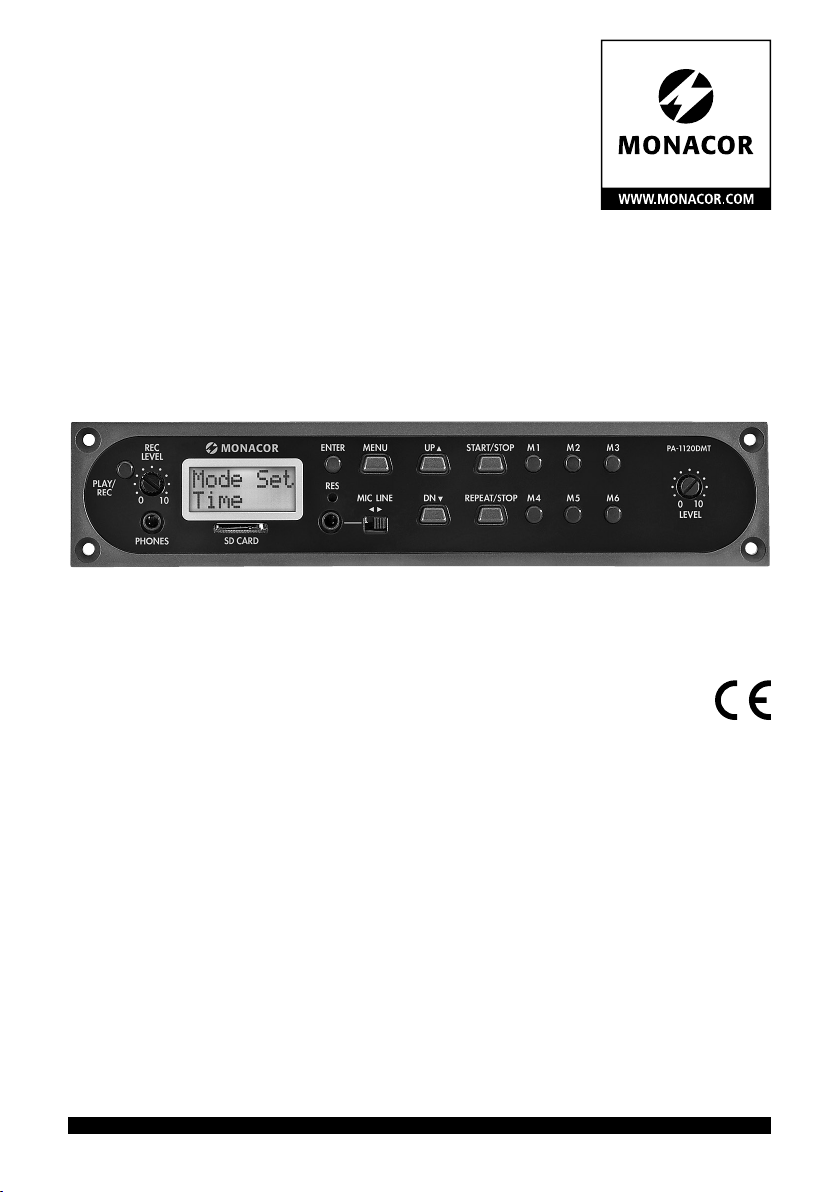
PA-1120DMT
Bestell-Nr. • Order No. 17.4580
EINBAU- und BEDIENUNGSANLEITUNG
INSTALLATION and OPERATING INSTRUCTIONS
NOTICE DE MONTAGE et D’UTILISATION
ISTRUZIONI PER IL MONTAGGIO e PER L’USO
INBOUW- en GEBRUIKSHANDLEIDING
INSTRUCCIONES INSTALACIÓN y FUNCIONAMIENTO
INSTALACJA i INSTRUKCJA OBSŁUGI
ELECTRONICS FOR SPECIALISTS ELECTRONICS FOR SPECIALISTS ELECTRONICS FOR SPECIALISTS ELECTRONICS FOR SPECIALISTS
Page 2

Deutsch ..........Seite 4
English ...........Page 14
Français ..........Page 24
Italiano...........Pagina 34
Nederlands .......Pagina 44
Español ..........Página 54
Polski ............Strona 64
ELECTRONICS FOR SPECIALISTS ELECTRONICS FOR SPECIALISTS ELECTRONICS FOR SPECIALISTS ELECTRONICS FOR SPECIALISTS
2
Page 3

PL AY/
REC
REC
LEVEL
0
PHONES
/
LINE
UP
DN
ENTER
RES
10
SD CARD
MIC
REPE AT
STOPMENU
/
STOP
M3M2M1START
PA-1120DMT
M6M5M4
0
LEVEL
10
➀
1 2 3 4
5 6 7 8 9 10 11 12 13 14 15 16
EMERGENCY DCF-77 EX-CONTROL
DIRECTION
RT = +5V
WS = DATA
SCREEN =
M1
EM
GND
M2 M3 M4 M5 M6
➂➁
17 18
19 20 21 22 2423 25 26 27
E/M TRIGGER
J1
low
hi
INPUT
STEREO
AUDIO OUT
L
R
G
PLAY
MODE
SELECTOR
DCF-77
INPUT
GND
+5 V
Data
TO RR-100/600 DCF-77/
REMOTE CONTROL
LED
GND
+5V
DATA
GND
START
REPEAT
POWER IN
BUSY
GND
G
Audio Out
+
➃
3
Page 4

Nachrichtenspeichereinschub
mitFunkuhr
Diese Anleitung richtet sich an Techniker, die das
Deutsch
Modul einbauen, und an Benutzer ohne besondere Fachkenntnisse. Bitte lesen Sie die Anleitung
vor dem Betrieb gründlich durch und heben Sie
sie für ein späteres Nachlesen auf.
Auf der ausklappbaren Seite 3 finden Sie alle
beschriebenen Bedienelemente und Anschlüsse.
Inhalt
1 Übersicht der Bedienelemente
undAnschlüsse . . . . . . . . . . . . 4
2 Hinweise für den sicherenGebrauch 5
3 Einsatzmöglichkeiten . . . . . . . . . 5
3.1 Speicherkapazität . . . . . . . . . . . . 6
4 Einbau und Anschlüsse . . . . . . . . 6
4.1 DCF77-Modul (Abb. 2) . . . . . . . . . 6
5 Grundeinstellungen . . . . . . . . . . 7
5.1 Emergency-Triggersignal wählen. . . . . 7
5.2 Wiedergabemodus wählen . . . . . . . 7
5.3 Uhr manuell stellen . . . . . . . . . . . 7
5.4 Ausgangspegel erhöhen. . . . . . . . .8
6 Bedienung . . . . . . . . . . . . . . . 8
6.1 Aufnahme . . . . . . . . . . . . . . . 8
6.1.1 Speicherplätze M1 – M6 . . . . . . . .8
6.1.2 Speicherplätze Voice01 – Voice20 . . . 8
6.2 Wiedergabe. . . . . . . . . . . . . . . 9
6.2.1 Speicherplätze M1 – M6 . . . . . . . .9
6.2.2 Nachricht ferngesteuert abrufen . . . . 9
6.2.3 Speicherplätze Voice01 – Voice20 . . 10
6.3 Nachricht löschen . . . . . . . . . . . 10
6.4 Nachrichtenfolge . . . . . . . . . . . 10
6.4.1 Nachrichtenfolge programmieren . . 10
6.4.2 Nachrichtenfolge abspielen . . . . . 11
6.5 Zeitgesteuerte Wiedergabe . . . . . . 11
6.5.1 Zeitplan erstellen . . . . . . . . . . 11
6.5.2 Programmdaten ändern oder löschen 12
6.5.3 Tagesplan kopieren . . . . . . . . . 12
6.6 Speicherkarte . . . . . . . . . . . . . 12
6.6.1 Audiodatei abspielen . . . . . . . . 13
6.6.2 Audiodatei kopieren . . . . . . . . 13
7 Technische Daten . . . . . . . . . . 13
4
1 Übersicht der Bedienelemente
undAnschlüsse
1
Taste PLAY/ REC zum Umschalten zwischen
Wiedergabe und Aufnahme für die Nachrichten M1 – M6
2
Regler REC LEVEL zum Einstellen des Auf-
nahmepegels
3
Kopfhöreranschluss PHONES als 3,5-mm-
Klinkenbuchse (mono, bei Stereokopfhörern
nur linke Seite), Mindestimpedanz des Kopfhörers 64 Ω
Bei Belegung der Buchse ist der Ausgang
„Audio Out“ (26) zum Verstärker stummgeschaltet.
4 Display
5 Schlitz für eine Speicherkarte
vom Typ „microSD“
6 Taste ENTER zum Aufruf eines Menüpunktes
und für die Bestätigung einer Eingabe
7
Audioeingang als 2-polige 3,5-mm-Klinken-
buchse zum Anschluss eines Mikrofons oder
einer Tonquelle mit Line-Ausgangspegel für
die Aufnahme einer Nachricht
8
versenkt eingebaute Rücksetztaste für den
Mikroprozessor des Einschubs (mit dünnem,
nicht elektrisch leitendem Gegenstand betätigen)
Der Prozessor wird wie nach dem Unterbrechen der Stromversorgung zurückgesetzt. Der
Nachrichtenspeicher sowie der Programmspeicher sind davon nicht betroffen.
9
Schalter MIC / LINE zur Wahl der Eingangsemp-
findlichkeit für den Audioeingang (7)
10
Taste MENU zum Aufruf und zum Abbruch
des Einstellmenüs
11
Taste DN zum Verringern der Anzahl der
Wiederholungen für die Wiedergabe einer
gewählten Nachricht, zur Wahl eines Menüpunktes und zum Verringern eines einzustellenden Wertes
12
Taste UP zum Erhöhen der Anzahl der Wieder-
holungen für die Wiedergabe einer gewählten
Nachricht, zur Wahl eines Menüpunktes und
zum Erhöhen eines einzustellenden Wertes
13 Taste REPEAT/ STOP zum Starten und Abbre-
chen der Wiedergabe einer Nachricht M1 – M6
mit den eingestellten Wiederholungen
Page 5
14
Taste START/ STOP zum Starten und Abbrechen
der einmaligen Wiedergabe einer Nachricht
M1 – 6
15 Tasten M1 – M6 zum Wählen eines Speicher-
platzes für die Aufnahme oder Wiedergabe
einer Nachricht
16
Regler LEVEL zum Einstellen der Wiederga-
belautstärke
17 DCF77-Funkuhrempfänger
18
Anschlussplatte für die Montage an der Rück-
seite des Verstärkers
19 Steckbrücke J1 zum Einstellen des Ausgangs-
pegels (Position hi = +10 dB)
20
Schalteingang zum Auslösen der Wiedergabe
der Notfallnachricht (M6), mit dem entsprechenden Anschlusskabel des Verstärkers zu
verbinden
21
zusätzlicher Audioausgang mit einem Ste-
reosignal (wird bei der Verwendung mit den
Verstärkern von MONACOR nicht benötigt)
22 Steckbrücke PLAY MODE SELECTOR zur Wahl
des Wiedergabemodus für die Nachrichten
M1 – M6
Wiedergabe nach dem Drücken der Taste
START/ STOP (14) oder REPEAT/ STOP (13)
unmittelbare (mehrmalige) Wiedergabe
beim Wählen der Nachricht mit den Tasten M1 – M6 (15)
23
zusätzlicher Eingang für DCF77-Funkuhr-
signale [wird bei der Verwendung mit den
Verstärkern von MONACOR nicht benötigt,
da die Verbindung über die Klemmen der Anschlussplatte (18) erfolgt]
24 Anschlussbuchse zur Fernsteuerung über das
Kommandomikrofon PA-1120RC, PA-6000RC
oder PA-2400RC: Mit dem entsprechenden
Anschlusskabel des Verstärkers verbinden.
25
Buchse zur Verbindung mit der Anschluss-
platte (18) über das beiliegende Flach bandkabel
26
Buchse zur Stromversorgung und für den
Audioausgang, mit dem entsprechenden
Anschlusskabel des Verstärkers zu verbinden
27
„Busy“-LED, leuchtet bei Aufnahme und Wie-
dergabe
2 Hinweise für den
sicherenGebrauch
Der Einschub entspricht allen relevanten Richtlinien der EU und trägt deshalb das -Zeichen.
Der Einschub darf nur von einer qualifizierten
•
Fachkraft eingebaut werden.
Verwenden Sie den Einschub nur im Innen-
•
bereich. Schützen Sie ihn vor Tropf- und
Spritzwasser, hoher Luftfeuchtigkeit und Hitze
(zulässiger Einsatztemperaturbereich 0 – 40 °C).
Nehmen Sie das Gerät mit dem eingebauten
•
Einschub nicht in Betrieb bzw. trennen Sie das
Gerät sofort von der Stromversorgung, wenn:
1.
sichtbare Schäden am Einschub, am Gerät
oder an der Netzanschlussleitung vorhanden sind,
2. nach einem Sturz oder Ähnlichem der Verdacht auf einen Defekt besteht,
3. Funktionsstörungen auftreten.
Geben Sie den Einschub oder das komplette
Gerät in jedem Fall zur Reparatur in eine Fachwerkstatt.
Verwenden Sie für die Reinigung nur ein tro-
•
ckenes, weiches Tuch, niemals Wasser oder
Chemikalien.
Wird der Einschub zweckentfremdet, nicht
•
fachgerecht eingebaut, falsch bedient oder
nicht fachgerecht repariert, kann keine Garantie für das Gerät und keine Haftung für daraus resultierende Sach- oder Personenschäden
übernommen werden.
Soll der Einschub endgültig aus dem Betrieb genommen werden, übergeben
Sie ihn zur umweltgerechten Entsorgung einem örtlichen Recycling betrieb.
3 Einsatzmöglichkeiten
Der Einschub PA-1120DMT ist ein Nachrichtenspeicher, mit dem sich 26 Sprachnachrichten
aufnehmen und wiedergeben lassen. Über eine
Speicherkarte vom Typ „microSD [HC]“ können
extern produzierte Aufnahmen in den Speicher
des Einschubs kopiert werden. Durch die integrierte Uhr mit einem DCF77-Funkuhrempfänger kann die Wiedergabe der Nachrichten auch
zeitgesteuert erfolgen. Ebenso ist über Schaltkontakte eine ferngesteuerte Wiedergabe von
Nachrichten sowie die Wiedergabe einer Notfalldurchsage möglich. Der Einschub ist speziell für
den Einsatz in einer ELA-Anlage konzipiert und
Deutsch
5
Page 6
zum Einbau z. B. in die folgenden Geräte von
MONACOR geeignet:
PA-1120
PA-1240
Deutsch
PA-1200 ELA-Verstärker für 4 Zonen
PA-1200EX Erweiterungsgerät für 2 Einschübe
PA-2410Z
PA-2420Z
PA-5240
PA-5480
PA-6240
PA-6480
PA-6600
ELA-Verstärker für 5 Zonen
ELA-Verstärker für 10 Zonen
ELA-Verstärker für 20 Zonen
ELA-Verstärker für 5 Zonen
ELA-Verstärker für 6 Zonen
3.1 Speicherkapazität
Der Einschub verfügt über 6 Speicherplätze „M1“
bis „M6“ mit je 2176 kByte, das entspricht einer
Aufnahmedauer* von je 360 s. Diese Nachrichten können automatisch über die eingebaute
Uhr abgerufen werden, über die Tasten (15), die
Schaltkontakte auf der Anschlussplatte (18) oder
über Tasten am Kommandomikrofon PA-1120RC,
PA-6000RC oder PA-2400RC (in Verbindung mit
einem Verstärker). Der Speicherplatz „M6“ ist
dabei für eine Notfalldurchsage vorgesehen, die
automatisch über den Verstärker [Anschluss „E / M
TRIGGER INPUT“ (20)] oder über einen Schließkontakt an den Klemmen „EMERGENCY“ auf
der Anschlussplatte (18) gestartet werden kann.
Weiterhin sind 20 Speicherplätze „Voice 01“
bis „Voice 20“ mit je 128 kByte vorhanden, das
entspricht einer Aufnahmedauer* von je 23 s.
Diese Nachrichten können automatisch über die
eingebaute Uhr oder manuell über das Menü
abgerufen werden.
Zudem kann ein Programm erstellt werden,
bei dem beliebige gespeicherte Nachrichten nacheinander wiedergegeben werden.
* Die maximal mögliche Dauer bei extern produzierten
Aufnahmen kann von dieser Angabe abweichen.
4 Einbau und Anschlüsse
WARNUNG
1) Den Gehäusedeckel des Verstärkers bzw. des
Grundgerätes abnehmen.
2)
Auf der Frontseite des Verstärkers bzw. des
6
Vor dem Einbau des Einschubs
den Netzstecker des Verstärkers
oder des Einschubgrundgerätes
aus der Steckdose ziehen. Anderenfalls besteht die Gefahr eines
elektrischen Schlages.
Grundgerätes die Abdeckblende für den Einschubschacht abschrauben.
3)
Vor dem Einsetzen des PA-1120DMT bei den
Verstärkern PA-1120, PA-1240, PA-2410Z, PA2420Z, PA-6240, PA-6480 und PA-6600 die
Steckbrücke MS2 in die Position PRI stecken
(siehe Anleitung des Verstärkers), damit eine
Durchsage des PA-1120DMT nicht durch ein anderes Signal in der Lautstärke abgesenkt wird.
4) Den Einschub einsetzen und festschrauben.
5) Den Stecker der freiliegenden dreipoligen Leitung des Verstärkers bzw. des Grundgerätes
in die Buchse „POWER IN / +, G, Audio Out“
(26) des Einschubs stecken. Hierüber wird der
Einschub mit 17 V ⎓ versorgt und das Audiosignal zum Verstärker geleitet.
6) Für eine über den Alarmeingang des Verstärkers ausgelöste Wiedergabe einer gespeicherten Notfalldurchsage bei den Verstärkern
PA-1120, PA-1240, PA-2410Z, PA-2420Z,
PA-6240, PA-6480 und PA-6600:
Vom Anschluss AS104 (AS-603 bei PA-2410Z
und PA-2420Z) der Platine, die sich ganz links
an der Rückseite des Verstärkers befindet, geht
eine zweipolige Leitung mit einer schwarzen
und braunen Ader ab. Das frei liegende Ende
dieser Leitung in das Stiftgehäuse CN104 des
Einschubs stecken.
7) Zum Einbau der Anschlussplatte (18) das Abdeckblech an der Rückseite des Verstärkers oder
des Grundgeräts entfernen. Die Anschlussplatte
von außen festschrauben und über das beiliegende Flachbandkabel mit der Buchse DCF-77/
REMOTE CONTROL (25) verbinden.
8)
Für einen Betrieb mit dem Kommandomikrofon
PA-1120RC, PA-6000RC oder PA-2400RC (z. B.
beim Verstärker PA-2410Z) den Stecker der
zehnpoligen Leitung in die Buchse TORR-100 /
600 (24) stecken. Diese dient dem Abruf von
Nachrichten über das Kommandomikrofon.
4.1 DCF77-Modul (Abb. 2)
Das Anschlusskabel des beiliegenden Empfangsmoduls (17) an die drei Klemmen „DCF-77“auf
der Anschlussplatte (18) anschließen:
Anschlusskabel Klemme
weiße Ader DATA
rote Ader
Abschirmung GND
Wichtig! Auf keinen Fall das Empfangsmodul
+5 V
Page 7

in einem metallischen Gehäuse (z. B. in einem
Rack) platzieren. Der Empfang des Funksignals
kann auch durch die Nähe von Metallteilen oder
elektromagnetischen Feldern (Transformatoren,
Computern, Starkstromleitungen etc.), beeinträchtigt werden. In diesem Fall muss der Empfänger anders platziert werden.
Wird das Zeitsignal empfangen, erscheint im
Display (4) zu jeder vollen Minute DCF77 ON.
5 Grundeinstellungen
5.1 Emergency-Triggersignal wählen
Für das ferngesteuerte Abrufen einer Notfalldurchsage über den Verstärker [Anschluss „E / M
TRIGGER INPUT“ (20)] oder die Klemmen „EMERGENCY“ auf der Anschlussplatte (18) kann die Art
des Triggersignals gewählt werden.
Hinweis: Diese Auswahl ist ausschließlich für die Notfalldurchsage, die über den Anschluss „E / M TRIGGER
INPUT“ oder über die Klemmen „EMERGENCY“ ausgelöst wird. Alle anderen Durchsagen werden davon
nicht beeinflusst!
1)
Den Verstärker bzw. das Grundgerät einschalten.
2) Die Taste MENU (10) drücken. Das Display (4)
zeigt:
Mode Set
Time
3) Die Taste UP (12) oder DN (11) so oft drücken,
bis in der unteren Displayzeile EM Type steht.
4)
Die Taste ENTER (6) drücken. Die obere Displayzeile zeigt jetzt
aktuelle Einstellung des Triggertyps.
5) Mit der Taste UP oder DN den Triggertyp wählen und die Auswahl mit der Taste ENTER bestätigen:
Latch Die Nachricht wird solange wiederholt,
Pulse Die Nachricht wird solange wieder-
Soll der aktuelle Triggertyp beibehalten werden, die Einstellung mit der Taste MENU abbrechen.
Hinweis: Wird ca. 30 s lang keine Taste gedrückt, beendet sich das Menü automatisch.
EM Type
, die untere Zeile die
wie das Triggersignal anliegt.
holt, bis die Taste START/ STOP (14)
gedrückt wird.
5.2 Wiedergabemodus wählen
Die Wiedergabe der Nachrichten von den 6
Hauptspeicherplätzen geschieht normalerweise
in zwei Schritten:
1. Auswahl der Nachricht
2. Start der (mehrmaligen) Wiedergabe
Dies gilt für die Wiedergabe sowohl über die Tasten
am Einschubmodul (☞ Kap. 6.2.1) als auch (ferngesteuert) über Schaltkontakte (☞Kap. 6.2.2).
Die unmittelbare Wiedergabe einer Nachricht
kann über das Umstecken der Steckbrücke PLAY
MODE SELECTOR (22) erreicht werden. Vor dem
Umstecken das Gerät ausschalten.
Wiedergabe nach dem Drücken der Taste
START/ STOP (14) oder REPEAT/ STOP (13)
unmittelbare (mehrmalige) Wiedergabe
beim Wählen der Nachricht mit den Tasten
M1 – M6 (15)
5.3 Uhr manuell stellen
Ist eine Synchronisation der eingebauten Uhr
über den Funksender nicht möglich oder nicht
erwünscht, kann die Uhr manuell gestellt werden.
1)
Den Verstärker bzw. das Grundgerät einschalten.
2) Die Taste MENU (10) drücken. Das Display (4)
zeigt:
Mode Set
Time
3)
Die Taste ENTER (6) drücken. Die obere Displayzeile zeigt jetzt
Zeile die aktuelle Einstellung des Wochentags.
4)
Mit der Taste UP (12) oder DN (11) den gewünschten Wochentag einstellen:
Mon Montag (Monday)
Tues Dienstag (Tuesday)
Wednes Mittwoch (Wednesday)
Thurs Donnerstag (Thursday)
Fri Freitag (Friday)
Satur Sonnabend (Saturday)
Sun Sonntag (Sunday)
5) Die Taste ENTER drücken. Die obere Display-
zeile zeigt jetzt
Hour: die aktuelle Einstellung der Stunde.
6)
Mit der Taste UP oder DN die Stunde einstellen
und mit der Taste ENTER bestätigen. Die untere
Displayzeile zeigt jetzt Min: und die aktuelle
Einstellung der Minute.
Week Set
Time Set
, die untere
, die untere Zeile
Deutsch
7
Page 8

7)
Mit der Taste UP oder DN die Minute einstellen
und mit der Taste ENTER bestätigen. Das Display zeigt jetzt den eingestellten Wochentag
und die Uhrzeit an.
Deutsch
Beim Empfang eines Zeitsignals zeigt das Display
DCF77 ON und die Uhr wird synchronisiert.
5.4 Ausgangspegel erhöhen
Bei Bedarf kann der Pegel des Ausgangssignals
um 10 dB erhöht werden. Dazu bei ausgeschaltetem Gerät die Steckbrücke J1 (19) von der
Position „low“ in die Position „hi“ umstecken.
6 Bedienung
Nach dem Einschalten des Verstärkers bzw.
Grundgerätes zeigt das Display (4) des Einschubs
den Wochentag und die Uhrzeit an. Zu dieser
Anzeige kehrt das Gerät auch immer automatisch zurück, wenn z. B. bei einem Menüaufruf
etwa 30 s lang keine Tastenbetätigung erfolgt.
Eine Menüeinstellung kann auch jederzeit mit der
Taste MENU (10) abgebrochen werden.
6.1 Aufnahme
Für die Aufnahme einer Nachricht ein Mikrofon
oder eine Mono-Tonquelle mit Line-Pegel an die
2-polige Klinkenbuchse (7) anschließen und den
Schalter (9) für die Eingangsempfindlichkeit entsprechend in die Position MIC (Mikrofon) oder
LINE (Line-Pegel) stellen.
Während einer Aufnahme wird das Eingangssignal über den Verstärker ausgegeben. Es lässt
sich aber auch über einen Kopfhörer kontrollieren. Den Kopfhörer (Mindestimpedanz 64 Ω) an
die Buchse PHONES (3) anschließen (mono, bei
Stereokopfhörern nur linke Seite). Dabei wird der
Ausgang (26) zum Verstärker stummgeschaltet.
Zur Verwendung extern produzierter Aufnahmen siehe Kapitel 6.6.
6.1.1 Speicherplätze M1 – M6
Zur Aufnahme einer Nachricht auf einen der Speicherplätze „M1“ bis „M6“:
1) Die Taste (15) des gewünschten Speicherplat-
zes drücken. Das Display zeigt z. B.
M3
PlayMode
Startet mit dem Drücken der Taste bereits die
Wiedergabe der gespeicherten Nachricht, diese
mit der Taste REPEAT/ STOP (13) abbrechen.
8
2) Die Taste PLAY/ REC (1) drücken. Das Display
schaltet auf den Aufnahmemodus um:
M3
Rec Mode
3)
Die Taste START/ STOP (14) drücken. In der
unteren Zeile des Displays erscheint zunächst
Erase
. Dabei wird der Speicherplatz gelöscht.
Die Aufnahme beginnt, wenn das Display
in der oberen Zeile hinter der Speichernummer
REC zeigt. In der unteren Zeile wird nun der
Pegel des Eingangssignals als Balken dargestellt.
4) Mit dem Regler REC LEVEL (2) den Pegel des
aufzunehmenden Signals so einstellen, dass
bei lauten Passagen noch nicht alle Segmente
des Balkens zu sehen sind.
5)
Zum Beenden der Aufnahme die Taste
START/ STOP drücken.
6.1.2 Speicherplätze Voice01 – Voice20
Zur Aufnahme einer Nachricht auf einen der Speicherplätze „Voice01“ bis „Voice20“:
1)
Die Taste MENU (10) drücken. Das Display
zeigt:
Mode Set
Time
2) Die Taste UP (12) oder DN (11) so oft drücken,
bis in der unteren Displayzeile Voice steht.
3) Die Taste ENTER (6) drücken. Das Display zeigt
jetzt:
Choose
Play
4) Mit der Taste UP oder DN die Option Rec in
der unteren Zeile wählen.
5)
Die Taste ENTER drücken. Das Display zeigt
jetzt:
Record
Voice:01
6) Mit der Taste UP oder DN den gewünschten
Speicherplatz für die Aufnahme wählen (
01
bis 20).
7)
Die Taste START/ STOP (14) oder ENTER drücken. In der unteren Displayzeile erscheint zunächst Erase. Dabei wird der Speicherplatz
gelöscht.
Die Aufnahme beginnt, wenn
Erase
ausgeblendet ist. Stattdessen wird nun der Pegel
des Eingangssignals als Balken dargestellt.
8) Mit dem Regler REC LEVEL (2) den Pegel des
aufzunehmenden Signals so einstellen, dass
Page 9

bei lauten Passagen noch nicht alle Segmente
des Balkens zu sehen sind.
9)
Zum Beenden der Aufnahme die Taste
START/ STOP oder ENTER drücken.
Das Display zeigt nun PlayBack und die Wiedergabe der aufgenommenen Nachricht kann
sofort mit der Taste START/ STOP erfolgen. Mit
der Taste UP oder DN lässt sich für die Wiedergabe auch ein anderer Speicherplatz wählen
(☞Kap.6.2.3).
Zum Verlassen des Menüs die Taste MENU
drücken.
6.2 Wiedergabe
Die Lautstärke für die Wiedergabe kann mit dem
Regler LEVEL (16) eingestellt werden. Den Regler
vor dem ersten Abspielen einer Nachricht etwa
in die Mittelposition drehen und während der
Wiedergabe ggf. korrigieren. Ist die Lautstärke
des Einschubs für den verwendeten Verstärker
trotz voll aufgedrehten Reglers noch zu gering,
lässt sich der Ausgangspegel um weitere 10 dB
anheben (☞ Kap. 5.4).
Ist die automatische Wiedergabe einer Notfalldurchsage vorgesehen, stellen Sie unbedingt
sicher, dass der Regler nicht versehentlich verdreht
werden kann.
Eine gespeicherte Nachricht lässt sich auch
über einen Kopfhörer vorhören. Den Kopfhörer
(Mindestimpedanz 64 Ω) an die Buchse PHONES
(3) anschließen (mono, bei Stereokopfhörern nur
linke Seite). Dabei wird der Ausgang (26) zum
Verstärker stummgeschaltet.
6.2.1 Speicherplätze M1 – M6
Die folgende Beschreibung bezieht sich auf den
normalen Wiedergabemodus. Für die unmittelbare Wiedergabe siehe Kapitel 6.2.1.1.
Zur einmaligen Wiedergabe einer zuvor aufgenommenen Nachricht von einem der Speicherplätze „M1“ bis „M6“:
1) Die Taste (15) des gewünschten Speicherplat-
zes drücken. Das Display zeigt z. B.:
M3 Rep2
PlayMode
2) Die Taste START/ STOP (14) drücken. Die Wie-
dergabe startet und in der unteren Displayzeile
wird Playing angezeigt.
3)
Zum Abbruch der Wiedergabe die Taste
START/ STOP erneut drücken.
Zur mehrmaligen Wiedergabe einer zuvor aufge
-
nommenen Nachricht:
1)
Die Taste des gewünschten Speicherplatzes
drücken. Das Display zeigt z. B.:
M3 Rep2 (Speicher M3, 2 × abspielen)
PlayMode
2)
Mit der Taste UP (12) oder DN (11) wählen, wie
oft die Nachricht hintereinander zu hören sein
soll: Rep1 bis Rep9 = 1 bis 9 × abspielen,
Rep0 = endlos wiederholen.
3)
Die Taste REPEAT/ STOP (13) drücken. Die Wiedergabe startet und in der unteren Displayzeile
wird Playing angezeigt.
4)
Zum Abbruch der Wiedergabe die Taste
REPEAT/ STOP erneut drücken.
An einem Kommandomikrofon PA-2400RC,
PA-1120RC oder PA-6000RC lässt sich ebenfalls
zunächst eine Nachricht M1 – M6 wählen und
dann die Wiedergabe über die Taste START/ STOP
oder eine mehrmalige Wiedergabe über die Taste
REPEAT/ STOP starten.
6.2.1.1 Unmittelbare Wiedergabe
Ist über die Steckbrücke PLAY MODE SELECTOR
(
Kap. 5.2) die unmittelbare Wiedergabe ge-
☞
wählt:
1) Die Taste (15) des gewünschten Speicherplatzes drücken. Das Display zeigt z. B.:
M3 Rep2 (Speicher M3, 2 × abspielen)
Playing
Die (mehrmalige) Wiedergabe startet sofort.
Die Häufigkeit wird hinter dem Speicherplatz
angezeigt.
2)
Zum Abbruch der Wiedergabe die Taste
REPEAT/ STOP (13) drücken.
3) Nach dem Abbruch der Wiedergabe lässt sich
mit der Taste UP (12) oder DN (11) die Häufigkeit für die Wiedergabe dieser Nachricht
ändern:
Rep1 bis Rep9 = 1 bis 9 × abspielen,
Rep0 = endlos wiederholen.
6.2.2 Nachricht ferngesteuert abrufen
Die in Kapitel 6.2.1 beschriebene Wiedergabe der
unter „M1“ bis „M6“ gespeicherten Nachrichten
über die Tasten des Einschubs kann auch über
die Schaltkontakte an der Anschlussplatte(18)
erfolgen. Dazu jeweils die mit der beschriebenen Taste gleichnamige Klemme (M1, … M6,
START [/STOP], REPEAT [/STOP]) über einen
Deutsch
9
Page 10
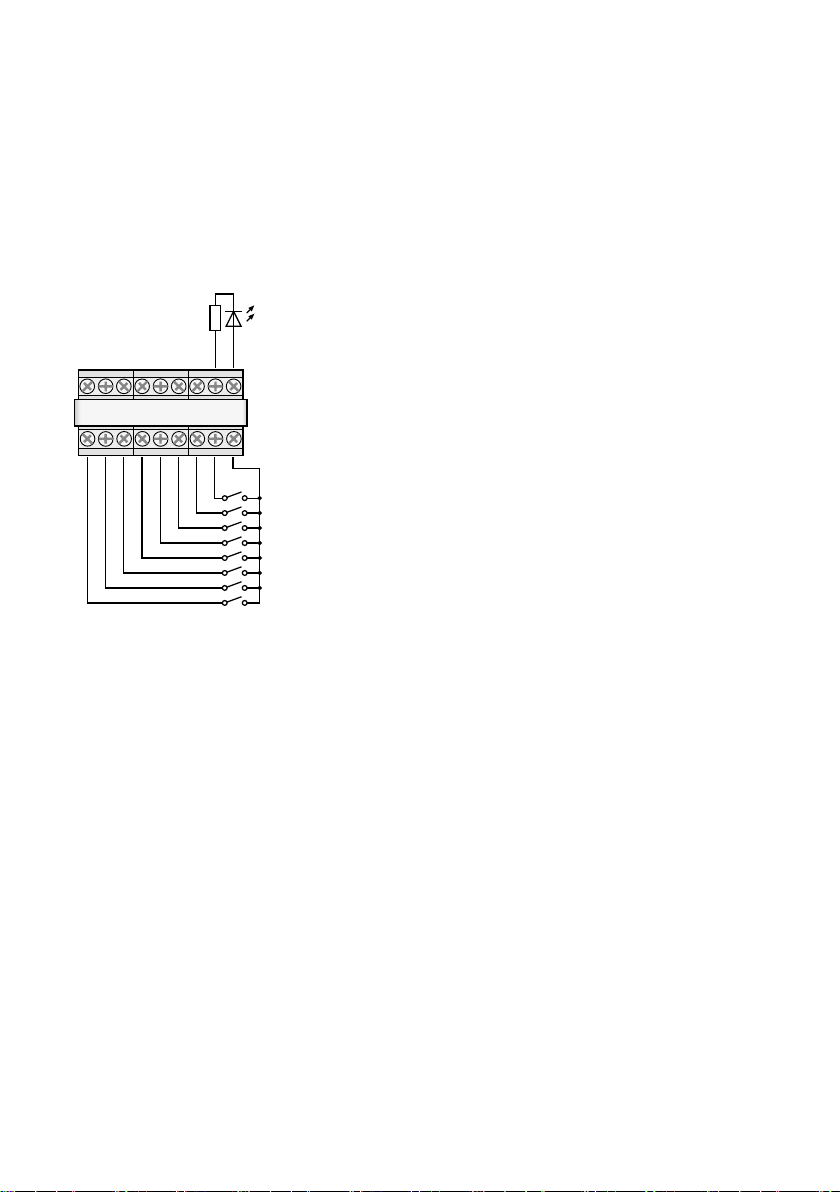
Schließkontakt kurz mit der Klemme GND verbinden. Die Änderung der Anzahl der Wiederholungen bei der mehrmaligen Wiedergabe muss jedoch über die Taste UP (12) oder DN (11) erfolgen.
Deutsch
Über die Klemme BUSY kann extern die
Aktivität des Einschubs angezeigt werden, wie
mit der LED (27) auf der Platine des Einschubs,
die bei einer Aufnahme oder Wiedergabe einer
Nachricht leuchtet. An der Klemme liegen in dem
Fall 3,3 V ⎓ gegen GND an. Hier kann z. B. eine
LED über einen geeigneten Vorwiderstand angeschlossen werden (☞ Abb. 5).
LED
+3,3 V
BUSY
GND
M1
M2 M3 M4 M5 M6
Anschluss für Fernsteuerung
➄
START
GND
REPEAT
6.2.3 Speicherplätze Voice01 – Voice20
Zur Wiedergabe einer Nachricht von einem der
Speicherplätze „Voice01“ bis „Voice20“:
1)
Die Taste MENU (10) drücken. Das Display zeigt:
Mode Set
Time
2) Die Taste UP (12) oder DN (11) so oft drücken,
bis in der unteren Displayzeile Voice steht.
3) Die Taste ENTER (6) drücken. Das Display zeigt
jetzt:
Choose
Play
4)
Die Taste ENTER drücken. Das Display zeigt
jetzt:
PlayBack
Voice:01
5)
Mit der Taste UP oder DN die gewünschte
Nachricht wählen (01 bis 20).
6)
Die Taste START/ STOP (14) oder ENTER drücken. Die obere Zeile zeigt jetzt Playing.
10
7)
Zum Abbrechen der Wiedergabe die Taste
START/ STOP oder ENTER drücken. Die obere
Zeile zeigt jetzt wieder
PlayBack
und es
kann eine andere Nachricht zur Wiedergabe
gewählt werden (☞ Bedienschritt 5).
6.3 Nachricht löschen
Zum Löschen einer Nachricht auf den Speicherplätzen Voice01 – Voice20, ohne dabei eine neue
Nachricht aufzunehmen:
1)
Die Taste MENU (10) drücken. Das Display
zeigt:
Mode Set
Time
2) Die Taste UP (12) oder DN (11) so oft drücken,
bis in der unteren Displayzeile Voice steht.
3) Die Taste ENTER (6) drücken. Das Display zeigt
jetzt:
Choose
Play
4)
Mit der Taste UP oder DN die Option
Delete
in der unteren Zeile wählen.
5)
Die Taste ENTER drücken. Das Display zeigt
jetzt:
Delete
Voice:01
6)
Mit der Taste UP oder DN die zu löschende
Nachricht wählen (01 bis 20) und mit der Taste
ENTER bestätigen.
Die Nachricht wird jetzt gelöscht und das Menü
verlassen. Zum Löschen weiterer Nachrichten wieder bei Bedienschritt 1 beginnen.
Hinweis: Nachrichten auf den Speicherplätzen M1 – M6
können nur durch eine neue Aufnahme gelöscht werden
(☞ Kap. 6.1.1).
6.4 Nachrichtenfolge
Eine Folge von bis zu 20 gespeicherten Nachrichten lässt sich in beliebiger Reihenfolge programmieren und manuell abspielen.
6.4.1 Nachrichtenfolge programmieren
1)
Die Taste MENU (10) drücken. Das Display
zeigt:
Mode Set
Time
2) Die Taste UP (12) oder DN (11) so oft drücken,
bis in der unteren Displayzeile RECALL steht.
3) Die Taste ENTER (6) drücken. Das Display zeigt
jetzt:
Page 11

RECALL
PGM Play
4)
Mit der Taste UP oder DN die Option PGM
Edit in der unteren Zeile wählen.
5)
Die Taste ENTER drücken. Das Display zeigt,
wenn noch kein Programm erstellt wurde:
PGM Edit
P01 ---
6)
Mit der Taste UP oder DN den Speicherplatz
(M1 – M6 oder V01 – V20 [„Voice“-Speicher])
für den ersten Programmschritt P01 wählen.
7)
Die Taste START/ STOP (14) drücken. Mit der
Taste UP oder DN den Speicherplatz für den
zweiten Programmschritt P02 wählen.
8)
Auf diese Weise alle abzuspielenden Nachrichten in der gewünschten Reihenfolge speichern.
Abschließend die Taste START/ STOP und dann
ENTER drücken oder ca. 30 s warten, bis die
Programmierung automatisch beendet wird.
Mit dem Drücken der Taste ENTER wird der
zuletzt angezeigte Programmschritt und alle
folgenden gelöscht und die Programmierung
verlassen. Es ist dann der Wiedergabemodus
angewählt (☞ Kap. 6.4.2).
Hinweis: Nach der Eingabe des 20. Schrittes kann die
Programmierung nur durch Warten verlassen werden,
da das Drücken der Taste ENTER alle Programmschritte
löschen würde.
6.4.2 Nachrichtenfolge abspielen
1)
Die Taste MENU (10) drücken. Das Display
zeigt:
Mode Set
Time
2) Die Taste UP (12) oder DN (11) so oft drücken,
bis in der unteren Displayzeile RECALL steht.
3) Die Taste ENTER (6) drücken. Das Display zeigt
jetzt:
RECALL
PGM Play
4)
Die Taste ENTER drücken. Das Display zeigt
z. B.:
PGM Play
P01 M6
5) Die Taste START/ STOP (14) drücken. Die Wiedergabe startet und das Display zeigt:
PGM Play
P01 ....
Die programmierten Nachrichten werden
nacheinander abgespielt und die Anzeige des
gespielten Programmschritts wechselt entsprechend: P01, P02, P03, …
6)
Zum Abbrechen der Wiedergabe die Taste
START/ STOP erneut drücken.
7) Beim Starten der Wiedergabe über die Taste
REPEAT/ STOP (13) hält die Wiedergabe nach
jeder abgespielten Nachricht an. Die im Programm folgende Nachricht kann durch erneutes Drücken der Taste gestartet werden.
Ein Drücken der Taste während der Wiedergabe bricht diese ab und wechselt zur nächsten Nachricht, die durch erneutes Drücken der
Taste wiedergegeben werden kann.
6.5 Zeitgesteuerte Wiedergabe
Die gespeicherten Nachrichten können regelmäßig
zu bestimmten Zeiten automatisch abgespielt werden. Dafür lassen sich für jeden Wochentag bis zu
20 unterschiedliche Wiedergabezeiten programmieren. Ist ein für einen Wochentag programmierter Zeitplan auch für andere Wochentage
zutreffend, kann dieser einfach kopiert werden.
6.5.1 Zeitplan erstellen
1)
Die Taste MENU (10) drücken. Das Display
zeigt:
Mode Set
Time
2)
Die Taste UP (12) drücken, sodass in der
unteren Displayzeile Program steht.
3) Die Taste ENTER (6) drücken. Das Display zeigt
jetzt:
Choose
Week Set
4) Die Taste ENTER drücken. Das Display zeigt:
Program
Mon
5) Mit der Taste UP oder DN (11) den gewünschten Wochentag einstellen (☞ Kap. 5.3).
6)
Die Taste ENTER drücken. Das Display zeigt
z. B.:
CH:01 01
16:10 21
(Programmplatz 1, 1 × abspielen,
Startzeitpunkt 16:10 Uhr, Nachricht M1)
Hinweis: Die Nachrichten Voice01 – 20 werden hier
mit den Nummern 01 – 20, die Nachrichten M1 – 6
mit den Nummern 21– 26 bezeichnet.
Deutsch
11
Page 12

7)
Mit der Taste UP oder DN einen freien Programmplatz
CH:XX --/--:-- --
und die Taste ENTER drücken. Das Display zeigt:
Program
Deutsch
Change
Die Taste ENTER drücken.
8)
Mit den Tasten UP, DN und ENTER jeweils
den gewünschten Wert für die Stunde
(Hour:), die Minute (Min:), die Nachricht
(
Voice:01
– 20 oder
M:1– 6
) sowie die Anzahl der Wiederholungen (Rep : 01– 09 =
1 bis 9 × abspielen, 00 = endlos wiederholen)
eingeben. Das Display zeigt dann z. B. zusammenfassend:
CH:03 01
16:10 21
(Programmplatz 3, 1 × abspielen,
Startzeitpunkt 16:10 Uhr, Nachricht M1)
Hinweis: Die Nachrichten Voice 01 – 20 werden hier mit
den Nummern 01 – 20, die Nachrichten M1 – 6 mit den
Nummern 21 – 26 bezeichnet.
Bei Bedarf weitere Programmpunkte erstellen
(☞Bedienschritt 7). Mit der Taste MENU das
Menü verlassen.
6.5.2 Programmdaten ändern oder löschen
Zum Ändern oder Löschen eines Tagesprogrammpunktes vorgehen, wie im vorangegangenen
Kapitel beschrieben ist. Im Bedienschritt 7 dann
den zu ändernden Programmplatz wählen und
mit ENTER bestätigen. Das Display zeigt:
Program
Change
Um neue Daten für den Programmpunkt einzugeben, die Taste ENTER drücken und mit dem
Bedienschritt 8 fortfahren.
Soll der Programmpunkt nur gelöscht werden,
die Taste UP drücken, sodass in der unteren Zeile
Delete
gezeigt wird und dann die Taste ENTER
drücken. Mit der Taste MENU das Menü verlassen.
6.5.3 Tagesplan kopieren
Soll ein programmierter Tagesplan auch für einen
anderen Wochentag gelten:
1)
Die Taste MENU (10) drücken. Das Display
zeigt:
Mode Set
Time
2) Die Taste UP (12) drücken, sodass in der unteren Displayzeile Program steht.
12
suchen
3) Die Taste ENTER (6) drücken. Das Display zeigt
jetzt:
Choose
Week Set
4)
Die Taste UP drücken, sodass in der unteren
Displayzeile Day Copy steht.
5)
Die Taste ENTER drücken. Das Display zeigt
jetzt z. B.:
Original
Mon
6)
Mit der Taste UP oder DN (11) den Wochentag
des zu kopierenden Tagesplans wählen.
7)
Die Taste ENTER drücken. Das Display zeigt
jetzt z. B.:
Copy Day
Mon
8)
Mit der Taste UP oder DN den Wochentag wählen, der denselben Tagesplan erhalten soll und
mit der Taste ENTER bestätigen.
Der Plan wird jetzt kopiert und das Menü verlassen. Zum Kopieren weiterer Wochentage wieder
bei Bedienschritt 1 beginnen.
6.6 Speicherkarte
Extern produzierte Aufnahmen lassen sich über
eine Speicherkarte1 vom Typ „microSD[HC]“ in
den Speicher des Einschubs kopieren. Dazu müssen die Dateien im MP3-Format gespeichert und
exakt nach der Bezeichnung des Zielspeicherplatzes benannt sein (z. B. „M6.mp3“ oder „Voice09.
mp3“)2. Zudem darf die Dateigröße die Kapazität
des Speicherplatzes nicht übersteigen:
„M1“ bis „M6“ max. je 2176 kByte
„Voice01“ bis „Voice20“ max. je 128 kByte
Die Speicherkarte in den Schlitz SD CARD (5) einsetzen (mit den Kontakten nach unten zeigend).
Die Karte in den Schlitz schieben, bis sie einrastet.
Soll die Karte wieder entnommen werden, sie
etwas hineindrücken, sodass sie ausrastet.
1
Aufgrund der Vielfalt von Speicher-Herstellern und
Gerätetreibern kann nicht garantiert werden, dass
alle Speicherkarten mit dem PA-1120DMT kompatibel sind.
2
Der Dateiname darf nicht zweimal die Endung „.mp3“
erhalten, sonst wird die Audiodatei nicht abgespielt.
Das kann leicht passieren, wenn unter Windows die
Anzeige der Dateiendungen ausgeschaltet ist. Zur
Kontrolle unbedingt die Anzeige der Dateiendungen
einschalten.
Windows i st ein registrierte s Warenzeichen der Microsoft Corpo ration in den USA und anderen Ländern.
Page 13

6.6.1 Audiodatei abspielen
Eine Audiodatei auf einer Speicherkarte kann über
das Menü wiedergegeben werden. Die zeitgesteuerte Wiedergabe oder die Integration in eine
programmierte Folge von Nachrichten ist aber erst
möglich, wenn die Datei in den internen Speicher
des Einschubs kopiert wurde (☞Kap.6.6.2). Zum
Abspielen einer Datei:
1)
Die Taste MENU (10) drücken. Das Display zeigt:
Mode Set
Time
2) Die Taste UP (12) oder DN (11) so oft drücken,
bis in der unteren Displayzeile
SD Card
steht.
3) Die Taste ENTER (6) drücken. Das Display zeigt
jetzt:
Choose
Play
Erscheint stattdessen
Check SD Card
, prü-
fen, ob die Karte richtig eingesteckt ist.
4)
Die Taste ENTER drücken. Das Display zeigt
jetzt:
PlayBack
Voice:01
5)
Mit der Taste UP oder DN die zu spielende Datei
(
M:1 – M:6
oder
Voice:01 – Voice:20
wählen.
6)
Mit der Taste START/ STOP (14) die Wiedergabe
starten. Während der Wiedergabe wechselt die
obere Zeile zu Playing.
Wenn die Wiedergabe nicht startet, kann
es daran liegen, dass keine Datei mit dem gewählten Namen auf der Karte ist, die Datei ein
falsches Format oder die falsche Größe hat.
6.6.2 Audiodatei kopieren
Zum Kopieren von Audiodateien in den Speicher
des Einschubs:
1)
Die Taste MENU (10) drücken. Das Display
zeigt:
Mode Set
Time
2) Die Taste UP (12) oder DN (11) so oft drücken,
bis in der unteren Displayzeile
SD Card
steht.
3) Die Taste ENTER (6) drücken. Das Display zeigt
jetzt:
Choose
Play
Erscheint stattdessen
Check SD Card
, prü-
fen, ob die Karte richtig eingesteckt ist.
4) Mit der Taste UP die Option Copy in der unteren Zeile wählen.
5)
Die Taste ENTER drücken. Das Display zeigt
jetzt:
Copy
Voice:01
6) Mit der Taste UP oder DN die zu kopierende
Datei (M:1 – M:6 / Voice:01 – Voice:20)
wählen.
7)
Die Taste ENTER drücken. Das Display zeigt
kurz
ERASE
, während die vorherige Nachricht
aus dem Speicher gelöscht wird und anschließend Copying sowie den Fortschritt des
Kopiervorgangs.
Anschließend können auf diese Weise weitere
Dateien kopiert werden (☞ Schritt 6).
Sollen alle geeigneten Dateien von der Speicherkarte in den Speicher des Einschubs kopiert werden, im Bedienschritt 4 die Option Copy All
wählen und die Taste ENTER drücken.
7 Technische Daten
Frequenzbereich
MIC: � � � � � � � � � � � � � � � �150 – 15 000 Hz
)
LINE: � � � � � � � � � � � � � � � 50 – 15 000 Hz
Audio-Eingang
Anschluss:� � � � � � � � � � � �3,5-mm-Klinkenbuchse,
asymmetrisch
Eingangsempfindlichkeit, Impedanz
MIC: � � � � � � � � � � � � � � � �2,5 mV, 600 Ω
LINE: � � � � � � � � � � � � � � �245 mV, 10 kΩ
Kopfhörerausgang
Ausgangsleistung: � � � � � � max� 24 mW an 64 Ω
Mindestimpedanz: � � � � � � 64 Ω
Speicherkapazität
„Voice01“ – „Voice20“: � �20 × 128 kByte (23 s*)
„M1“ – „M6“: � � � � � � � � 6 × 2176 kByte (360 s*)
* bei Aufnahmen über
den PA-1120DMT
Stromversorgung:
Einsatztemperatur: � � � � � � � 0 – 40 °C
Abmessungen (B × H × T): � 194 × 40 × 85 mm
Gewicht: � � � � � � � � � � � � � �270 g
Änderungen vorbehalten.
Diese Bedienungsanleitung ist urheberrechtlich für MONACOR ® INTERNATIONAL GmbH & Co. KG geschützt.
Eine Reproduktion für eigene kommerzielle Zwecke – auch
auszugsweise – ist untersagt.
� � � � � � � 15 – 17 V (⎓), 150 mA
Deutsch
13
Page 14

Message Storage Insertion
Module with Radio Clock
These instructions are intended for technicians
English
installing the module and for users without any
specific technical knowledge. Please read the instructions carefully prior to operation and keep
them for later reference.
All operating elements and connections de-
scribed can be found on the fold-out page 3.
Contents
1 Control Elements and Connections . 14
2 Safety Notes. . . . . . . . . . . . . 15
3 Applications . . . . . . . . . . . . . 15
3.1 Storage capacity . . . . . . . . . . . 16
4 Installation and Connections . . . . 16
4.1 DCF77 module (fig. 2). . . . . . . . . 16
5 Basic Settings . . . . . . . . . . . . 17
5.1 Selecting the emergencytriggersignal. 17
5.2 Selecting the replay mode . . . . . . . 17
5.3 Setting the clock manually . . . . . . 17
5.4 Increasing the output level . . . . . . 17
6 Operation . . . . . . . . . . . . . . 18
6.1 Recording. . . . . . . . . . . . . . . 18
6.1.1 Storage locations M1 – M6 . . . . . 18
6.1.2 Storage locations Voice01 – Voice20 . 18
6.2 Replay . . . . . . . . . . . . . . . . 19
6.2.1 Storage locations M1 – M6 . . . . . 19
6.2.2 Calling up a message by
remote control . . . . . . . . . . . 19
6.2.3 Storage locations Voice01 – Voice20 . 20
6.3 Deleting a message . . . . . . . . . . 20
6.4 Message sequence . . . . . . . . . . 20
6.4.1 Programming a message sequence . 20
6.4.2 Replaying a message sequence . . . 21
6.5 Time-controlled replay. . . . . . . . . 21
6.5.1 Creating a schedule . . . . . . . . . 21
6.5.2 Changing or deleting program data . 22
6.5.3 Copying a day schedule . . . . . . . 22
6.6 Memory card . . . . . . . . . . . . . 22
6.6.1 Replaying an audio file . . . . . . . 22
6.6.2 Copying an audio file . . . . . . . . 23
7 Specifications . . . . . . . . . . . . 23
14
1 Control Elements and
Connections
1
Button PLAY/ REC to switch between replay
and recording for the messages M1 – M6
2
Control REC LEVEL to adjust the recording level
3
Headphone connection PHONES (3.5 mm jack;
mono, left side only for stereo headphones),
minimum impedance of the headphones 64 Ω
When this jack is used, the output “Audio
Out” (26) to the amplifier will be muted.
4 Display
5 Slot for a memory card (type “microSD”)
6 Button ENTER to call up a menu item and to
confirm an entry
7 Audio input (2-pole 3.5 mm jack) to connect
a microphone or an audio source with line
output level for recording a message
8 Recessed reset button for the microprocessor
of the insertion module (use a thin, non-conductive object to press the button)
The processor will be reset (as it is after the
power supply was interrupted). This reset will
not apply to the message memory and the
program memory.
9 Switch MIC / LINE to select the input sensitivity
for the audio input (7)
10
Button MENU to call up or cancel a setting
menu
11 Button DN to reduce the number of repeats
for the replay of a selected message, to select
a menu item and to reduce a value to be set
12 Button UP to increase the number of repeats
for the replay of a selected message, to select
a menu item and to increase a value to be set
13 Button REPEAT/ STOP to start and stop the re-
play of a message M1 – M6 with the repeats
set
14
Button START/ STOP to start and stop the one-
time replay of a message M1 – M6
15 Buttons M1 – M6 to select a storage location
for recording or replaying a message
16
Control LEVEL to adjust the volume of the
replay
17 DCF77 radio clock receiver
18 Connection plate to be mounted on the rear
side of the amplifier
19 Jumper J1 to adjust the output level
(position hi = +10 dB)
Page 15
20
Switching input to trigger the replay of an
emergency message (M6); to be connected
to the corresponding connection cable of the
amplifier
21 Additional audio output with a stereo signal
(not required when used with amplifiers from
MONACOR)
22 Jumper PLAY MODE SELECTOR to select the
replay mode for the messages M1 – M6
replay after the button START/ STOP (14)
or REPEAT/ STOP (13) was pressed
immediate (multiple) replay when the
message is selected by means of the
buttons M1 – M6 (15)
23
Additional input for DCF77 radio clock signals
[not required when used with amplifiers from
MONACOR as the connection is made via the
terminals of the connection plate (18)]
24
Connection jack for remote control of the
module via the zone paging microphone
PA-1120RC, PA-6000RC or PA-2400RC; connect the jack to the corresponding connection
cable of the amplifier
25
Jack for connection to the connection plate
(18) via the ribbon cable supplied
26 Jack for power supply and for the audio out-
put; to be connected to the corresponding
connection cable of the amplifier
27
“Busy” LED, will light up during recording and
replay
2 Safety Notes
The insertion module corresponds to all relevant
directives of the EU and is therefore marked
with .
The insertion module must be installed by
•
skilled personnel only.
The insertion module is suitable for indoor
•
use only. Protect it against dripping water and
splash water, high air humidity and heat (admissible ambient temperature range: 0 – 40 °C).
Do not operate the unit with the installed in-
•
sertion module and immediately disconnect the
unit from the power supply
1.
if the insertion module, the unit or the mains
cable is visibly damaged,
2.
if a defect might have occurred after the unit
was dropped or suffered a similar accident,
3. if malfunctions occur.
In any case the insertion module or the entire
unit must be repaired by skilled personnel.
For cleaning only use a dry, soft cloth; never
•
use water or chemicals.
No guarantee claims for the insertion module
•
and no liability for any resulting personal damage or material damage will be accepted if the
insertion module is used for other purposes
than originally intended, if it is not correctly
installed or operated, or if it is not repaired in
an expert way.
If the insertion module is to be put out
of operation definitively, take it to a
local recycling plant for a disposal which
is not harmful to the environment.
3 Applications
The insertion module PA-1120DMT is a message
storage module for storing and replaying 26 voice
messages. Using a memory card (type “microSD
[HC]”), externally created recordings can be copied to the memory of the insertion module. The
integrated clock with a DCF77 radio clock receiver allows for time-controlled message replay.
For remote-controlled message replay and for
emergency message replay, switching contacts
can be used. The insertion module has been especially designed for PA systems and is suitable
for installation e. g. in the following units from
MONACOR:
PA-1120
PA-1240
PA-1200 PA amplifier for 4 zones
PA-1200EX Basic unit for 2 insertion modules
PA-2410Z
PA-2420Z
PA-5240
PA-5480
PA-6240
PA-6480
PA-6600
PA amplifier for 5 zones
PA amplifier for 10 zones
PA amplifier for 20 zones
PA amplifier for 5 zones
PA amplifier for 6 zones
English
15
Page 16
3.1 Storage capacity
The insertion module provides 6 storage locations
(“M1” to “M6”) with 2176 kBytes each which
English
corresponds to a recording time* of 360seconds for each message. These messages can be
called up automatically via the integrated clock,
the buttons (15), the switching contacts on the
connection plate (18) or via buttons of the zone
paging microphone, PA-1120RC, PA-6000RC or
PA-2400RC (in combination with an amplifier).
The storage location “M6” is reserved for an
emergency message that is automatically started
via the amplifier [connection “E / M TRIGGER
INPUT” (20)] or via a normally open contact at
the terminals “EMERGENCY” on the connection
plate (18).
In addition, 20 storage locations (“Voice01”
to “Voice20”) with 128 kBytes each are available which corresponds to a recording time* of
23seconds for each message. These messages
can be called up automatically via the integrated
clock or manually via the menu.
Additionally, a program may be created to
replay any stored messages one after the other.
* Different maximum recording times may apply to ex-
ternally created recordings.
4 Installation and Connections
WARNING
1) Remove the housing cover from the amplifier
or basic unit.
2)
Remove the insertion compartment cover from
the front side of the amplifier or basic unit.
3) Prior to installing the insertion module PA-
1120DMT into the amplifiers PA-1120, PA1240, PA-2410Z, PA-2420Z, PA-6240, PA-6480
and PA-6600, rearrange the jumper MS2 to the
position PRI (see instructions of the amplifier);
thus, other signals will not reduce the volume
of announcements made by PA-1120DMT.
4) Insert the insertion module, and then fasten
it using screws.
Prior to installing the insertion
module, disconnect the mains plug
of the amplifier or basic unit from
the mains socket. Otherwise, there
is a risk of electric shock.
5)
Connect the plug of the exposed 3-pole
cable of the amplifier or basic unit to the jack
“POWER IN / +, G, Audio Out” (26) of the insertion module. This will supply the insertion
module with 17 V ⎓ and will send the audio
signal to the amplifier.
6)
To trigger the replay of a stored emergency
message via the alarm input of the amplifiers
PA-1120, PA-1240, PA-2410Z, PA-2420Z,
PA-6240, PA-6480 and PA-6600:
The PCB which is completely at the left of the
rear panel of the amplifier has a connection
AS104 (AS-603 for PA-2410Z and PA-2420Z)
with a two-pole line with a black core and a
brown core. Connect the bare end of this line
to the pin housing CN104 of the insertion.
7)
To install the connection plate (18), remove the
cover plate from the rear side of the amplifier
or basic unit. Screw the connection plate to
the amplifier or basic unit from the outside and
then connect it to the jack DCF-77/ REMOTE
CONTROL (25) using the ribbon cable supplied.
8) To operate the insertion module with a zone
paging microphone PA-1120RC, PA-6000RC or
PA-2400RC (e. g. with the amplifier PA-2410Z),
connect the plug of the 10-pole cable to the
jack TO RR-100 / 600 (24). This cable is used
to call up messages via the zone paging microphone.
4.1 DCF77 module (fig. 2)
Connect the connection cable of the reception
module (17) supplied to the three terminals
“DCF-77” of the connection plate(18):
Connection cable Terminal
white wire DATA
red wire
shield GND
Important! Never place the reception module in
a metal housing (e. g. rack). Nearby metal parts or
electromagnetic fields (transformers, computers,
power lines etc.) may interfere with radio signal
reception. If applicable, place the receiver at a
different location.
When a time signal is received, DCF77 ON will
appear on the display (4) every full minute.
+5 V
16
Page 17

5 Basic Settings
5.1 Selecting the
emergencytriggersignal
The type of trigger signal can be selected for remote-controlled retrieval of an emergency message via the amplifier [connection “E / M TRIGGER
INPUT” (20)] or via the terminals “EMERGENCY”
on the connection plate (18).
Note: This selection is exclusively made for the emergency announcement triggered via the connection “E / M
TRIGGER INPUT” or via the terminals “EMERGENCY”.
It will not affect any other announcements.
1) Switch on the amplifier or the basic unit.
2)
Press the button MENU (10). The display (4)
will show:
Mode Set
Time
3)
Press the button UP (12) or DN (11) repeatedly
until EM Type appears on the lower line of
the display.
4)
Press the button ENTER (6). EM Type will
now appear on the first line of the display;
the lower line will show the current trigger
type setting.
5)
Use the button UP or DN to select the trigger type and then press the button ENTER to
confirm:
Latch The message will be repeated as long
as the trigger signal is available.
Pulse
The message will be repeated until the
button START/ STOP (14) is pressed.
To stay with the current trigger type, cancel the
setting by means of the button MENU.
Note: The menu will be automatically exited after
approx. 30 seconds if no button is pressed.
5.2 Selecting the replay mode
The replay of messages stored on the six main
storage locations usually consists of two steps:
1. Selecting the message
2. Starting the (multiple) replay
This applies both to the replay via the buttons
on the insertion module (☞ chapter 6.2.1) and
to the (remote-controlled) replay via switching
contacts (☞ chapter 6.2.2).
For immediate message replay, rearrange the
jumper PLAY MODE SELECTOR (22). Switch off
the unit prior to rearranging the jumper.
replay after the button START/ STOP (14) or
REPEAT/ STOP (13) was pressed
immediate (multiple) replay when the mes-
sage is selected by means of the buttons
M1 – M6 (15)
5.3 Setting the clock manually
The clock can be manually set if synchronisation
of the integrated clock via the wireless transmitter
is not possible or not desired.
1) Switch on the amplifier or the basic unit.
2)
Press the button MENU (10). The display (4)
will show:
Mode Set
Time
3)
Press the button ENTER (6). Week Set will
now appear on the first line of the display;
the lower line will show the current weekday
setting.
4) Use the button UP (12) or DN (11) to set the
weekday desired:
Mon Monday
Tues Tuesday
Wednes Wednesday
Thurs Thursday
Fri Friday
Satur Saturday
Sun Sunday
5) Press the button ENTER. Time Set will appear on the first line of the display; the lower
line will show
Hour:
and the current hour
setting.
6) Use the button UP or DN to set the hour and
then press the button ENTER to confirm. The
lower display line will now show
Min:
and
the current minute setting.
7)
Use the button UP or DN to set the minute
and then press the button ENTER to confirm.
The display will now show the weekday and
the time set.
When a time signal is received, DCF77 ON will
appear on the display and the clock will be synchronised.
5.4 Increasing the output level
If required, the output level can be increased by
10 dB: Switch off the unit and then rearrange
the jumper J1 (19) from the position “low” to
the position “hi”.
English
17
Page 18

6 Operation
When the amplifier or the basic unit is switched
on, the display (4) of the insertion module will
English
show the weekday and the time. The unit will
always automatically return to this indication
after 30seconds when, for example, no button
is pressed in a menu. To cancel a menu setting at
any time, press the button MENU (10).
6.1 Recording
To record a message, connect a microphone or a
mono audio source with line level to the 2-pole
jack (7) and set the switch (9) for the input sensitivity to the corresponding position: MIC (microphone) or LINE (line level).
During recording, the input signal will be
replayed via the amplifier. However, it is also
possible to use headphones for monitoring the
input signal: Connect the headphones (minimum
impedance: 64 Ω) to the jack PHONES (3) [mono,
only the left side for stereo headphones); the output (26) to the amplifier will be muted.
Please refer to chapter 6.6 for information on
how to use externally created recordings.
6.1.1 Storage locations M1 – M6
To record a message on one of the storage locations “M1” to “M6”:
1) Press the button (15) of the storage location
desired. The display will show, for example:
M3
PlayMode
If pressing this button starts the replay of the
stored message, press the button REPEAT/ STOP
(13) to stop the replay.
2)
Press the button PLAY/ REC (1). The display will
switch to the recording mode:
M3
Rec Mode
3)
Press the button START/ STOP (14). First,
Erase will appear on the lower line of the
display and the storage location will be cleared.
Recording will start when the first line of
the display shows REC, following the storage
number. On the lower line, a bar graph will
appear, indicating the level of the input signal.
4)
Use the control REC LEVEL (2) to adjust the
level of the signal to be recorded in such a way
that not all segments of the bar graph will be
shown for peaks.
5)
To stop the recording, press the button
START/ STOP.
6.1.2 Storage locations Voice01 – Voice20
To record a message on one of the storage locations “Voice01” to “Voice20”:
1) Press the button MENU (10). The display will
show:
Mode Set
Time
2)
Press the button UP (12) or DN (11) repeatedly
until Voice appears on the lower line of the
display.
3)
Press the button ENTER (6). The display will
now show:
Choose
Play
4) Use the button UP or DN to select the option
Rec on the lower line.
5) Press the button ENTER. The display will now
show:
Record
Voice:01
6) Use the button UP or DN to select the storage
location desired for the recording (01 to 20).
7) Press the button START/ STOP (14) or ENTER.
First, Erase will appear on the lower line of
the display and the storage location will be
cleared.
Recording will start when
Erase
disappears. A bar graph will appear instead, indicating the level of the input signal.
8)
Use the control REC LEVEL (2) to adjust the
level of the signal to be recorded in such a way
that not all segments of the bar graph will be
shown for peaks.
9)
To stop the recording, press the button
START/ STOP or ENTER.
Now,
PlayBack
will appear on the display; the
button START/ STOP can be pressed to immediately replay the message stored. To select a different storage location for replay, use the button UP
or DN (☞ chapter 6.2.3).
To exit the menu, press the button MENU.
18
Page 19

6.2 Replay
Use the control LEVEL (16) to adjust the volume
of the messages replayed. Prior to the first message replay, turn the control approx. to midposition and, if required, adjust the control during
replay. If the volume of the insertion module is
too low for the amplifier used even though the
control has been turned to the right stop, the
output level may be increased by another 10 dB
(☞ chapter5.4).
If an emergency message is to be replayed
automatically, make absolutely sure to prevent
any inadvertent readjustment of the control.
Headphones can be used to monitor a stored
message: Connect the headphones (minimum
impedance: 64 Ω) to the jack PHONES (3) [mono,
only the left side for stereo headphones]; the output (26) to the amplifier will be muted.
6.2.1 Storage locations M1 – M6
The following description applies to the normal
replay mode. Please refer to chapter 6.2.1.1 for
the immediate replay mode.
For one-time replay of a message that has
been recorded on one of the storage locations
“M1” to “M6”:
1) Press the button (15) of the storage location
desired. The display will show, for example:
M3 Rep2
PlayMode
2) Press the button START/ STOP (14). The replay
will start and
Playing
will appear on the
lower display line.
3)
To stop the replay, press the button START/ STOP
again.
For multiple replay of a recorded message:
1)
Press the button of the storage location desired. The display will show, for example:
M3 Rep2 (storage location M3,
PlayMode replayed twice)
2)
Use the button UP (12) or DN (11) to define the
number of message repeats:
Rep1
to
Rep9
=
replayed 1 to 9 times, Rep0 = repeated continuously.
3)
Press the button REPEAT/ STOP (13). The replay
will start and
Playing
will appear on the
lower display line.
4)
To stop the replay, press the button
REPEAT/ STOP again.
At a zone paging microphone PA-2400RC,
PA-1120RC or PA-6000, it is also possible to select
a message M1 – M6 and then to start the replay by
means of the button START/ STOP or to start multiple replay by means of the button REPEAT/ STOP.
6.2.1.1 Immediate replay
If immediate replay has been selected by means
of the jumper PLAY MODE SELECTOR (
☞
chap-
ter5.2):
1) Press the button (15) of the storage location
desired. The display will now show, for example:
1) M3 Rep2 (storage location M3,
Playing replayed twice)
The (multiple) replay will start immediately. The
number of replays will be indicated next to the
storage location.
2) To stop the replay, press the button REPEAT/
STOP (13).
3)
When the replay has been stopped, the button
UP (12) or DN (11) can be used to change the
number of message repeats:
Rep1 to Rep9 = replayed 1 to 9 times,
Rep0 = repeated continuously.
6.2.2 Calling up a message by remote control
Instead of the buttons of the insertion module
(cf. chapter 6.2.1), the switching contacts on the
connection plate (18) can be used to replay the
messages that have been recorded on the storage
locations “M1” to “M6”: Briefly connect the terminal with the name of the corresponding button
(M1, … M6, START [/STOP], REPEAT [/STOP]) to the
terminal GND (via a normally open contact). The
number of repeats for multiple message replay,
however, can only be changed via the buttons UP
(12) and DN (11).
Use the terminal BUSY to externally indicate
insertion module activity [analogous to the LED indicator (27) on the circuit of the insertion module
that lights up when a message is being recorded
or replayed]. In this case, the terminal will provide
3,3 V ⎓ against GND, and an LED, for example,
can be connected via a suitable series resistor
(☞fig.5, page 20).
English
19
Page 20

LED
+3,3 V
BUSY
START
GND
GND
REPEAT
English
M1
M2 M3 M4 M5 M6
Connection for remote control
➄
6.2.3 Storage locations Voice01 – Voice20
To replay a message from one of the storage
locations “Voice01” to “Voice20”:
1) Press the button MENU (10). The display will
show:
Mode Set
Time
2)
Press the button UP (12) or DN (11) repeatedly
until
Voice
appears on the lower display line.
3)
Press the button ENTER (6). The display will
now show:
Choose
Play
4) Press the button ENTER. The display will now
show:
PlayBack
Voice:01
5)
Use the button UP or DN to select the message
desired (01 to 20).
6) Press the button START/ STOP (14) or ENTER.
Playing will appear on the first line of the
display.
7)
Press the button START/ STOP or ENTER to stop
the replay.
PlayBack
will appear on the first
line; a different message can be selected for
replay (☞ step 5).
20
6.3 Deleting a message
To delete a message from the storage locations
Voice01 to Voice20 without recording a new
message:
1) Press the button MENU (10). The display will
show:
Mode Set
Time
2)
Press the button UP (12) or DN (11) repeatedly
until
Voice
appears on the lower display line.
3)
Press the button ENTER (6). The display will
now show:
Choose
Play
4) Use the button UP or DN to select the option
Delete on the lower line.
5) Press the button ENTER. The display will now
show:
Delete
Voice:01
6)
Use the button UP or DN to select the message
to be deleted (01 to 20) and then press the
button ENTER to confirm.
The message will be deleted and the menu will
be exited. To delete further messages, start with
step 1 again.
Note: Messages that are stored on the storage locations M1 – M6 can only be deleted by a new recording
(☞chapter 6.1.1).
6.4 Message sequence
A sequence of up to 20 stored messages may be
programmed and manually replayed in any order.
6.4.1 Programming a message sequence
1) Press the button MENU (10). The display will
show:
Mode Set
Time
2)
Press the button UP (12) or DN (11) repeatedly
until
RECALL
appears on the lower display
line.
3)
Press the button ENTER (6). The display will
now show:
RECALL
PGM Play
4) Use the button UP or DN to select the option
PGM Edit on the lower line.
Page 21

5)
Press the button ENTER. If no program has
been created yet, the display will show:
PGM Edit
P01 ---
6) Use the button UP or DN to select the storage
location (M1 – M6 or V01 – V20 [“voice” storage]) for the first program step P01.
7)
Press the button START/ STOP (14). Use the button UP or DN to select the storage location for
the second program step P02.
8) Proceed in the same way to store all messages
to be replayed in the desired order. Finally,
press the button START/ STOP and then the button ENTER or wait for approx. 30 seconds until
programming will be automatically finished.
Pressing the button ENTER will delete the
program step most recently shown, delete the
subsequent program steps and exit programming. Then the replay mode will be selected
again (☞ chapter 6.4.2).
Note: When program step 20 has been entered, wait
for approx. 30 seconds to exit programming; pressing
the button ENTER will delete all program steps.
6.4.2 Replaying a message sequence
1) Press the button MENU (10). The display will
show:
Mode Set
Time
2)
Press the button UP (12) or DN (11) repeatedly
until
RECALL
appears on the lower display
line.
3)
Press the button ENTER (6). The display will
now show:
RECALL
PGM Play
4)
Press the button ENTER. The display will show,
for example:
PGM Play
P01 M6
5) Press the button START/ STOP (14). The replay
will start and the display will now show:
PGM Play
P01 ....
The programmed messages will be replayed
one after the other and the indication of the
program step replayed will change accordingly:
P01, P02, P03, …
6)
To stop the replay, press the button START/ STOP
again.
7) When the replay is started via the button REPEAT/ STOP (13), the replay will stop after each
message. To start the subsequent message of
the program, press the button again.
Pressing the button while a message is
being replayed will stop the message; to replay the next message, press the button again.
6.5 Time-controlled replay
The stored messages may automatically and
regularly be replayed at specific times; for each
weekday, up to 20 different times for replay can
be defined. The schedule of a weekday can be
copied to other weekdays, if required.
6.5.1 Creating a schedule
1) Press the button MENU (10). The display will
show:
Mode Set
Time
2)
Press the button UP (12) so that
Program
will
appear on the lower display line.
3)
Press the button ENTER (6). The display will
now show:
Choose
Week Set
4)
Press the button ENTER. The display will show:
Program
Mon
5)
Press the button UP or DN (11) to set the weekday desired (☞chapter 5.3).
6)
Press the button ENTER. The display will show,
for example:
CH:01 01
16:10 21
(program location 1, replay once,
start time 16:10 h, message M1)
Note: The numbers 01 – 20 indicate the messages
Voice01 – 20; the numbers 21 – 26 indicate the messages M1 – M6.
7) Use the button UP or DN to search for a free
program location
CH:XX --/--:-- --
and then press the button ENTER. The display
will show:
Program
Change
Press the button ENTER.
English
21
Page 22

8)
Use the buttons UP, DN and ENTER to enter the
values desired for the hour (Hour:), the minute (
Min:
), the message (
or M:1– 6) and the number of repeats
English
Voice:01
(Rep : 01– 09 = replayed 1 to 9 times,
00= repeated continuously). The display will
then show a “summary” of the values entered,
for example:
CH:03 01
16:10 21
(program location 3, replayed once,
start time 16:10 h, message M1)
Note: The numbers 01 – 20 indicate the messages
Voice01 – 20; the numbers 21 – 26 indicate the messages M1 – M6.
If required, create further program items
(☞step7). To exit the menu, press the button
MENU.
6.5.2 Changing or deleting program data
To change or delete a day program item, proceed
as described in the previous chapter. In step 7,
select the program location to be changed and
then press the button ENTER to confirm. The display will show:
Program
Change
To enter new data for the program item, press the
button ENTER and proceed with step 8.
To delete the program item, press the button UP
so that Delete will appear on the lower line;
then press the button ENTER. To exit the menu,
press the button MENU.
6.5.3 Copying a day schedule
To copy a programmed day schedule to another
weekday:
1) Press the button MENU (10). The display will
show:
Mode Set
Time
2)
Press the button UP (12) so that
Program
appear on the lower display line.
3)
Press the button ENTER (6). The display will
now show:
Choose
Week Set
4)
Press the button UP so that
Day Copy
appear on the lower line of the display.
22
5) Press the button ENTER. The display will now
show, for example:
– 20
Original
Mon
6)
Use the button UP or DN (11) to select the
weekday of the day schedule to be copied.
7) Press the button ENTER. The display will now
show, for example:
Copy Day
Mon
8)
Use the button UP or DN to select the weekday
to which the day schedule is to be copied; then
press the button ENTER.
The schedule will be copied and the menu will
be exited. To copy further weekday schedules,
start with step 1.
6.6 Memory card
Using a memory card1 (type “microSD[HC]”), externally created recordings can be copied to the
memory of the insertion module. The files must
have been saved in the format “mp3” and their
names must be identical to those of the target
storage locations to be used (e. g. “M6.mp3” or
“Voice09.mp3”)2. In addition, the file size must
not exceed the capacity of the corresponding
storage location:
“M1” to “M6”: up to 2176 kBytes each
“Voice01” to “Voice20”: up to 128 kBytes each
Insert the memory card into the slot SD CARD (5),
with the contacts facing downwards. Slide the
card into the slot until it engages. To remove the
card, slightly push the card so that it disengages.
1
Due to the large number of storage device manufactur-
ers and device drivers, it cannot be guaranteed that all
memory cards are compatible with the PA-1120DMT.
2
If the file name contains the extension „.mp3“ twice,
the audio file will not be replayed. This will easily happen when the display of file extensions in Windows has
been deactivated and the file extensions are hidden.
Always make sure to activate the feature so that the
file extensions are shown.
Windows is a registered trademark of Microsoft Corporation in the
will
USA and other countries.
6.6.1 Replaying an audio file
An audio file on a memory card can be replayed by
means of the menu. To allow for time-controlled
replay or for integration into a programmed message sequence, however, the audio file must first
will
be copied to the internal memory of the insertion
module (☞chapter 6.6.2). To replay an audio file:
Page 23

1) Press the button MENU (10). The display will
show:
Mode Set
Time
2)
Press the button UP (12) or DN (11) repeatedly
until SD Card appears on the lower display
line.
3)
Press the button ENTER (6). The display will
now show:
Choose
Play
If
Check SD Card
appears on the display,
check if the card has been properly inserted
into the slot.
4) Press the button ENTER. The display will now
show:
PlayBack
Voice:01
5)
Use the button UP or DN to select the
audio file to be replayed (M:1 – M:6 or
Voice:01 – Voice:20).
6) Press the button START/ STOP (14) to start the
replay. During replay, the indication on the first
line of the display will change to Playing.
If the replay fails to start, there may be no
file with the selected name on the memory
card or the format or the size of the file may
not be correct.
6.6.2 Copying an audio file
To copy audio files to the memory of the insertion
module:
1) Press the button MENU (10). The display will
show:
Mode Set
Time
2)
Press the button UP (12) or DN (11) repeatedly
until SD Card appears on the lower display
line.
3)
Press the button ENTER (6). The display will
now show:
Choose
Play
If Check SD Card appears on the display,
check if the card has been properly inserted
into the slot.
4) Use the button UP to select the option Copy
on the lower line.
5) Press the button ENTER. The display will now
show:
Copy
Voice:01
6) Use the button UP or DN to select the file to be
copied (
M:1
–
M:6 / Voice:01
7)
Press the button ENTER.
–
ERASE
Voice:20
will briefly
).
appear on the display while the previous message is being deleted from the storage. Then,
the display will show Copying and indicate
the progress of the copying process.
Then, if required, proceed in the same way to
copy further audio files (☞ step 6).
To copy all suitable audio files from the memory card to the memory of the insertion module,
select the option
Copy All
in step 4 and press
the button ENTER.
7 Specifications
Frequency range
MIC: � � � � � � � � � � � � � � � �150 – 15 000 Hz
LINE: � � � � � � � � � � � � � � � 50 – 15 000 Hz
Audio input
Connection: � � � � � � � � � � 3�5 mm jack,
unbalanced
Input sensitivity, impedance
MIC: � � � � � � � � � � � � � � � 2�5 mV, 600 Ω
LINE: � � � � � � � � � � � � � � �245 mV, 10 kΩ
Headphone output
Output power: � � � � � � � �24 mW max� at 64 Ω
Minimum impedance: � � � 64 Ω
Storage capacity
“Voice01” – “Voice20”: � � 20 × 128 kBytes
(23 sec�*)
“M1” – “M6”: � � � � � � � � � 6 × 2176 kBytes
(360 sec�*)
* for recordings via
PA-1120DMT
Power supply: � � � � � � � � � � 15 – 17 V (⎓), 150 mA
Ambient temperature: � � � � 0 – 40 °C
Dimensions (W × H × D): � � 194 × 40 × 85 mm
Weight: � � � � � � � � � � � � � � � 270 g
Subject to technical modification.
All rights reserved by MONACOR ® INTERNATIONAL GmbH
& Co. KG. No part of this instruction manual may be
reproduced in any form or by any means for any commercial use.
English
23
Page 24

Module de mémoire de
messages avec horloge radio
Cette notice s’adresse aux techniciens installant le mo-
Français
dule et aux utilisateurs sans connaissances techniques
particulières� Veuillez lire la notice avant l’utilisation et
conservez-la pour pouvoir vous y reporter ultérieurement�
Vous trouverez sur la page 3, dépliable, les éléments
et branchements décrits�
Table des matières
1 Eléments et branchements . . . . . 24
2 Conseils d’utilisation et desécurité. 25
3 Possibilités d’utilisation . . . . . . . 25
3.1 Capacité de mémoire . . . . . . . . . 26
4 Installation et branchements . . . . 26
4.1 Module DCF77 (schéma. 2) . . . . . . 26
5 Réglages de base . . . . . . . . . . 27
5.1 Sélection du signal Trigger Emergency
(urgence) . . . . . . . . . . . . . . . 27
5.2 Sélection du mode de lecture . . . . . 27
5.3 Réglage manuel de l’horloge . . . . . 27
5.4 Augmentation du niveau de sortie. . . 28
6 Utilisation . . . . . . . . . . . . . . 28
6.1 Enregistrement . . . . . . . . . . . . 28
6.1.1 Emplacements de mémoire M1 – M6. 28
6.1.2 Emplacements de mémoire
Voice01 – Voice20 . . . . . . . . . . 28
6.2 Lecture . . . . . . . . . . . . . . . . 29
6.2.1 Emplacements de mémoire M1 – M6. 29
6.2.2 Appeler un message à distance . . . 29
6.2.3 Emplacements de mémoire
Voice01 – Voice20 . . . . . . . . . . 30
6.3 Effacement d’un message . . . . . . . 30
6.4 Suite de messages. . . . . . . . . . . 30
6.4.1 Programmation d’une suite
de messages
6.4.2 Lecture d’une suite de messages . . 31
6.5 Message programmé . . . . . . . . . 31
6.5.1 Création d’un planing . . . . . . . . 31
6.5.2 Modifications ou effacement des
données de programmation . . . . . 32
6.5.3 Copie d’un planing journalier . . . . 32
6.6 Carte mémoire . . . . . . . . . . . . 32
6.6.1 Lecture de fichier audio . . . . . . . 33
6.6.2 Copie d’un fichier audio. . . . . . . 33
7 Caractéristiques techniques. . . . . 33
24
. . . . . . . . . . . . 30
1 Eléments et branchements
1
Touche PLAY/ REC pour commuter entre la lec-
ture et l’enregistrement pour les messages
M1 – M6
2
Réglage REC LEVEL pour régler le niveau d’en-
registrement
3
Prise casque PHONES, jack 3,5 femelle (mono,
pour des casques stéréo, uniquement côté
gauche), impédance minimale du casque 64 Ω
Si la prise est utilisée, la sortie «Audio
Out»(26) vers l’amplificateur est coupée.
4 Affichage
5
Fente pour une carte mémoire de type
«microSD»
6
Touche ENTER pour appeler un point de menu
et pour confirmer une saisie
7
Entrée audio, jack 3,5 femelle 2 pôles pour
brancher un microphone ou une source audio
avec niveau de sortie ligne pour l’enregistrement d’un message
8
Touche de réinitialisation encastrée pour le
micro-processeur du module (à activer avec
un objet fin non conducteur)
Le processeur est réinitialisé comme après une
coupure de l’alimentation. La mémoire des
messages et la mémoire des programmes ne
sont pas concernés.
9
Interrupteur MIC / LINE pour sélectionner la
sensibilité d’entrée pour l’entrée audio (7)
10
Touche MENU pour appeler et quitter le menu
de réglage
11
Touche DN pour diminuer le nombre de répéti-
tions de lecture pour un message sélectionné,
pour sélectionner un point du menu et pour
diminuer une valeur à régler
12 Touche UP pour augmenter le nombre de ré-
pétitions de lecture pour un message sélectionné, pour sélectionner un point du menu
et pour augmenter une valeur à régler
13 Touche REPEAT/ STOP pour démarrer et inter-
rompre la lecture d’un message M1 – M6 avec
des répétitions réglées
14
Touche START/ STOP pour démarrer et inter-
rompre la répétition unique d’un message
M1 – M6
15
Touches M1 – M6 pour sélectionner un em-
placement de mémoire pour enregistrer ou
lire un message
Page 25

16
Réglage LEVEL pour régler le volume de la
lecture
17 Récepteur horloge radio DCF77
18 Platine de branchement pour le montage sur
la face arrière de l’amplificateur
19
Cavalier J1 pour régler le niveau de sortie
(position hi = +10 dB)
20
Entrée de commutation pour déclencher la
restitution d’une annonce d’urgence (M6), à
relier au cordon de branchement correspondant de l’amplificateur
21
Sortie audio supplémentaire avec un signal
stéréo (n’est pas nécessaire si vous l’utilisez
avec les amplificateurs de MONACOR)
22
Cavalier PLAY MODE SELECTOR pour sélec-
tionner le mode lecture pour les messages
M1 – M6
Lecture après une pression sur la touche
START/ STOP (14) ou REPEAT/ STOP (13)
Lecture immédiate (répétée) en sélection-
nant le message avec les touches M1 – M6
(15)
23
Entrée supplémentaire pour les signaux
radio DCF77 [pas nécessaire si vous l’utilisez avec des amplificateurs MONACOR car
la connexion s’effectue via les bornes sur la
platine de branchement (18)]
24
Prise de branchement pour gestion à distance
via le microphone de commande PA-1120RC,
PA-6000RC ou PA-2400RC : à relier avec le
cordon correspondant de l’amplificateur
25
Prise pour relier la platine de branchement (18)
via le câble plat livré
26
Prise pour l’alimentation et pour la sortie
audio, à relier au cordon de branchement
correspondant de l’amplificateur
27 LED «Busy», brille lors d’enregistrement et de
lecture
2 Conseils d’utilisation et
desécurité
Le module répond à toutes les directives nécessaires de l’Union européenne et porte donc le
symbole .
Seul un personnel qualifié peut procéder à l’ins-
•
tallation du module.
Le module n‘est conçu que pour une utilisa-
•
tion en intérieur. Protégez-le de tout type de
projections d‘eau, des éclaboussures, d‘une humidité élevée et de la chaleur (plage de température de fonctionnement autorisée 0 – 40 °C).
Ne faites jamais fonctionner l’appareil avec le
•
module installé et débranchez immédiatement
l’appareil lorsque :
1. des dommages sur le module, l‘appareil ou
sur le cordon secteur apparaissent.
2. après une chute ou accident similaire, vous
avez un doute sur l‘état de l‘appareil.
3. des défaillances apparaissent.
Dans tous les cas, les dommages doivent être
réparés par un technicien spécialisé.
Pour nettoyer l‘appareil, utilisez uniquement un
•
chiffon sec et doux, en aucun cas de produits
chimiques ou d‘eau.
Nous déclinons toute responsabilité en cas de
•
dommages corporels ou matériels résultants
si le module est utilisé dans un but autre que
celui pour lequel il a été conçu, s‘il n‘est pas
correctement branché ou utilisé ou s‘il n‘est pas
réparé par une personne habilitée ; de même,
la garantie deviendrait caduque.
Lorsque le module est définitivement
retiré du service, vous devez le déposer
dans une usine de recyclage de proximité pour contribuer à son élimination
non polluante.
CARTONS ET EMBALLAGE
PAPIER À TRIER
3 Possibilités d’utilisation
Le module PA-1120DMT est un module de mémoire de messages avec lequel on peut enregistrer 26 messages et les restituer. Via une carte
mémoire de type «microSD [HC]», on peut copier
dans la mémoire du module des enregistrements
produits en externe. Via l’horloge intégrée avec
un récepteur radio DCF77, la restitution des
messages programmée peut être effectuée. De
même, une restitution gérée à distance de message et la restitution d’une annonce d’urgence
sont possibles via des contacts de commutation.
Le module est spécialement conçu pour une utilisation dans des installations Public Adress et peut
être inséré p. ex. dans les appareils MONACOR
suivants :
Français
25
Page 26

PA-1120
PA-1240
PA-1200 amplificateur PA pour 4 zones
PA-1200EX appareil de base pour 2 modules
Français
PA-2410Z
PA-2420Z
PA-5240
PA-5480
PA-6240
PA-6480
PA-6600
amplificateur PA pour 5 zones
amplificateur PA pour 10 zones
amplificateur PA pour 20 zones
amplificateur PA pour 5 zones
amplificateur PA pour 6 zones
3.1 Capacité de mémoire
Le module dispose de 6 emplacements de mémoire «M1» à «M6» avec respectivement 2176
Ko, ce qui correspond à une durée d’enregistrement* de 360 s pour chaque message. Ces
messages peuvent être appelés automatiquement via l’horloge intégrée, via les touches (15),
les contacts de commutation sur la platine de
branchement (18) ou les touches sur le microphone de commande PA-1120RC, PA-6000RC ou
PA-2400RC (en combinaison avec un amplificateur). L’emplacement de mémoire «M6» est prévu
pour une annonce d’urgence qui peut être automatiquement démarrée via l’amplificateur [branchement «E / M TRIGGER INPUT» (20)] ou via un
contact de fermeture aux bornes «EMERGENCY»
sur la platine de branchement (18).
De plus, 20 emplacements de mémoires
(«Voice 01» à «Voice20») avec chacun 128 Ko
sont prévus, ce qui correspond à une durée
d’enregistrement* de 23 secondes pour chaque
message. Ces messages peuvent être appelés
automatiquement via l’horloge intégrée ou manuellement via le menu.
De plus, on peut créer un programme dans
lequel les messages mémorisés peuvent être lus
les uns à la suite des autres.
* La durée maximale possible pour des enregistrements
produits en externe peut être différente de cette donnée.
4 Installation et branchements
AVERTISSEMENT
1)
Retirez le couvercle du boîtier de l’amplificateur
ou de l’appareil de base.
2)
Sur la face avant de l’amplificateur ou de
26
Avant d’installer le module,
débranchez l’amplificateur ou
l’appareil de base sinon il y a
risque de décharge électrique.
l’appareil de base, dévissez le cache pour le
tiroir du module.
3)
Avant d’insérer le PA-1120DMT dans les
amplificateurs PA-1120, PA-1240, PA-2410Z,
PA-2420Z, PA-6240, PA-6480 et PA-6600,
mettez le cavalier MS2 sur la position PRI (voir
notice de l‘amplificateur), pour que volume
d’une annonce du PA-1120DMT ne soit pas
diminué par un autre signal.
4) Insérez le module et vissez.
5)
Branchez la fiche du cordon trois pôles exposé
de l’amplificateur ou de l’appareil de base dans
la prise «POWER IN / +, G, Audio Out» (26) du
module. Le module est alors alimenté par une
tension 17 V ⎓, le signal audio est dirigé vers
l’amplificateur.
6)
Pour une restitution d’une annonce d’urgence
mémorisée, déclenchée par l’entrée alarme des
amplificateurs PA-1120, PA-1240, PA-2410Z,
PA-2420Z, PA-6240, PA-6480 et PA-6600 :
La platine tout à gauche sur la face arrière de
amplificateur possède une connexion AS104
(AS-603 pour PA-2410Z et PA-2420Z) avec un
câble deux pôles avec un conducteur noir et
un conducteur marron. Mettez l’extrémité libre
de ce câble au boîtier de connexion CN104
du module.
7)
Pour insérer la platine de branchement (18),
retirez le cache sur la face arrière de l‘amplificateur ou de l’appareil de base. Vissez la platine
de branchement de l’extérieur et via le câble
plat livré, reliez-la à la prise DCF-77/ REMOTE
CONTROL (25).
8) Pour un fonctionnement avec le microphone
de commande PA-1120RC, PA-6000RC ou PA2400RC (p. ex. avec l’amplificateur PA-2410Z),
branchez la fiche du câble 10 pôles à la prise
TO RR-100 / 600 (24). Le câble sert pour appeler
des messages via le microphone de commande.
4.1 Module DCF77 (schéma. 2)
Reliez le câble de branchement du module de
réception (17) livré aux trois bornes «DCF-77»
sur la platine de branchement (18):
Câble de branchement Borne
conducteur blanc DATA
conducteur rouge
blindage GND
Important ! Ne placez en aucun cas le module
dans un boîtier métallique (par exemple un rack).
+5 V
Page 27

La réception du signal radio peut être perturbée
par la proximité d’éléments métalliques ou par
des champs électromagnétiques (transformateurs,
ordinateurs, câbles courants forts etc.). Dans ce
cas, il faut placer le récepteur à un autre endroit.
Lorsque le signal de l’heure est reçu, DCF77 ON
est visible sur l’affichage (4) à chaque minute
pleine.
5 Réglages de base
5.1 Sélection du signal Trigger Emergency (urgence)
Pour appeler à distance une annonce d’urgence
via l’amplificateur [branchement «E / M TRIGGER
INPUT» (20)] ou via les bornes «EMERGENCY» sur
la platine de branchement (18), il est possible de
sélectionner le type de signal Trigger.
Remarque : Cette sélection est exclusivement prévue
pour l’annonce d’urgence déclenchée via le branchement «E / M TRIGGER INPUT» ou via les bornes «EMERGENCY». Toutes les autres annonces ne sont pas
influencées.
1) Allumez l’amplificateur ou l’appareil de base.
2) Appuyez sur la touche MENU (10). L’affichage
(4) indique :
Mode Set
Time
3)
Appuyez sur la touche UP (12) ou DN (11)
jusqu’à ce que EM Type soit visible dans la
ligne inférieure de l’affichage.
4)
Appuyez sur la touche ENTER (6). La ligne
supérieure de l’affichage indique maintenant
EM Type, la ligne inférieure le réglage actuel
du type de signal Trigger.
5) Avec la touche UP ou DN, sélectionnez le type
de signal Trigger et confirmez la sélection avec
la touche ENTER :
Latch Le message est répété tant que le
signal Trigger est présent.
Pulse Le message est répété jusqu’à ce que la
touche START/ STOP (14) soit activée.
Si le type de signal Trigger actuel doit être
conservé, annulez le réglage avec la touche
MENU.
Conseil : Si aucune touche n’est enfoncée pendant
30 secondes environ, le menu s’arrête automatiquement.
5.2 Sélection du mode de lecture
La lecture de messages des 6 emplacements principaux de mémoire s’effectue normalement en
deux étapes :
1. Sélection du message
2. Démarrage de la lecture (répétée)
Ceci vaut pour la lecture via les touches sur le
module insert (☞ chapitre 6.2.1) et également
pour la lecture (à distance) via les contacts de
commutation (☞ chapitre 6.2.2).
La lecture immédiate d’un message peut être
obtenue en déplaçant le cavalier PLAY MODE
SELECTOR (22). Eteignez l’appareil pour déplacer
le cavalier.
Lecture après une pression sur la touche
START/ STOP (14) ou REPEAT/ STOP (13)
Lecture immédiate (répétée) en sélectionnant
le message avec les touches M1 – M6 (15)
5.3 Réglage manuel de l’horloge
Si une synchronisation de l’horloge intégrée via
l’émetteur radio n’est pas possible ou n’est pas souhaitée, l’horloge peut être réglée manuellement.
1) Allumez l’amplificateur ou l’appareil de base.
2) Appuyez sur la touche MENU (10). L’affichage
(4) indique :
Mode Set
Time
3)
Appuyez sur la touche ENTER (6). La ligne
supérieure de l’affichage indique maintenant
Week Set
du jour de la semaine.
4) Avec la touche UP (12) ou DN (11), réglez le
jour de la semaine souhaité :
Mon lundi (Monday)
Tues mardi (Tuesday)
Wednes mercredi (Wednesday)
Thurs jeudi (Thursday)
Fri vendredi (Friday)
Satur samedi (Saturday)
Sun dimanche (Sunday)
5) Appuyez sur la touche ENTER. La ligne supé-
rieure de l’affichage indique
ligne inférieure Hour: le réglage actuel de
l’heure.
6)
Avec la touche UP ou DN, réglez l’heure et
confirmez avec la touche ENTER. La ligne inférieure de l’affichage indique maintenant Min:
et le réglage actuel des minutes.
, la ligne inférieure le réglage actuel
Time Set
, la
Français
27
Page 28

7) Avec la touche UP ou DN, réglez les minutes
et confirmez avec la touche ENTER. L’affichage
indique maintenant le jour de la semaine réglé
et l’heure.
Français
Lors de la réception d’un signal d’heure, l’affichage indique DCF77 ON et l’horloge est synchronisée.
5.4 Augmentation du niveau de sortie
Si besoin, le niveau du signal de sortie peut être
augmenté de 10 dB. Pour ce faire, lorsque l’appareil est éteint, déplacez le cavalier J1 (19) de la
position «low» sur la position «hi».
6 Utilisation
Une fois l’amplificateur ou l’appareil de base
allumé, l’affichage (4) du module indique le
jour de la semaine et l’heure. L’appareil revient
automatiquement à cet affichage si par exemple
aucune touche n’est activée pendant 30 secondes
environ dans un menu. Il est possible d’interrompre un réglage de menu à tout moment avec
la touche MENU (10).
6.1 Enregistrement
Pour l’enregistrement d’un message, reliez un
microphone ou une source audio mono avec
niveau ligne à la prise jack 2 pôles (7) et mettez
l’interrupteur (9) pour la sensibilité d’entrée soit
sur la position MIC (microphone) soit sur la position LINE (niveau ligne).
Pendant un enregistrement, le signal d’entrée
est dirigé via l’amplificateur. Il peut également
être contrôlé par un casque. Reliez le casque (impédance minimale 64 Ω) à la prise PHONES (3)
(mono, pour des casques stéréo, uniquement
côté gauche). La sortie (26) vers l’amplificateur
est coupée.
Pour utiliser des enregistrements produits en
externe, voir chapitre
6.1.1 Emplacements de mémoire M1 – M6
Pour enregistrer un message dans un des emplacements «M1» à «M6» :
1) Appuyez sur la touche (15) de l’emplacement
souhaité ; l’affichage indique par exemple :
M3
PlayMode
Si, en appuyant sur la touche, la lecture du
message mémorisé démarre déjà, arrêtez-la
avec la touche REPEAT/ STOP (13).
2)
Appuyez sur la touche PLAY/ REC (1) ; l’affichage commute sur le mode d’enregistrement :
28
6.6.
M3
Rec Mode
3)
Appuyez sur la touche START/ STOP (14) ; dans
la ligne inférieure de l’affichage, Erase est
tout d’abord affiché. L’emplacement de mémoire est effacé.
L’enregistrement débute lorsque l’affichage
indique dans la ligne supérieure, derrière le
numéro de l’emplacement, REC. Dans la
ligne inférieure, le niveau du signal d’entrée
est indiqué sous forme de bargraphe.
4)
Avec le réglage REC LEVEL (2), réglez le niveau
du signal à enregistrer de telle sorte que pour
des passages forts, tous les segments du
bargraphe ne soient pas visibles.
5) Pour arrêter l’enregistrement, appuyez sur la
touche START/ STOP.
6.1.2 Emplacements de mémoire
Voice01 – Voice20
Pour enregistrer un message dans un des emplacements «Voice01» à «Voice20» :
1)
Appuyez sur la touche MENU (10) ; l’affichage
indique par exemple :
Mode Set
Time
2)
Appuyez sur la touche UP (12) ou DN (11)
jusqu’à ce que
Voice
soit visible dans la ligne
inférieure de l’affichage.
3) Appuyez sur la touche ENTER (6) ; l’affichage
indique :
Choose
Play
4)
Avec la touche UP ou DN, sélectionnez l’option
Rec dans la ligne inférieure.
5) Appuyez sur la touche ENTER ; l’affichage indique maintenant :
Record
Voice:01
6) Avec la touche UP ou DN, sélectionnez l’emplacement de mémoire souhaité pour l’enregistrement (01 à 20).
7)
Appuyez sur la touche START/ STOP (14) ou
ENTER. Dans la ligne inférieure de l’affichage,
Erase
est tout d’abord affiché. L’emplace-
ment de mémoire est effacé.
L’enregistrement débute lorsque
Erase
n’est plus affiché. A la place, le niveau du signal
d’entrée est maintenant indiqué sous forme
de bargraphe.
Page 29

8)
Avec le réglage REC LEVEL (2), réglez le
niveau du signal à enregistrer de telle sorte que
pour des passages forts, tous les segments du
bargraphe ne soient pas visibles.
9) Pour arrêter l’enregistrement, appuyez sur la
touche START/ STOP ou ENTER.
L’affichage indique maintenant
PlayBack
et la
lecture du message enregistré peut démarrer avec
la touche START/ STOP. Avec la touche UP ou DN,
vous pouvez sélectionner un autre emplacement
pour la lecture (☞ chapitre 6.2.3.
Pour quitter le menu, appuyez sur la touche MENU.
6.2 Lecture
Le volume pour la lecture peut être réglé avec le
réglage LEVEL (16). Avant la première diffusion
d’un message, tournez le réglage sur la position
médiane environ et pendant la lecture, corrigez
si besoin. Si le volume du module pour l’amplificateur utilisé est encore trop faible, même si le
réglage est encore complètement tourné vers la
droite, vous pouvez augmenter le niveau de sortie
de 10 dB supplémentaires (☞ chapitre 5.4).
Si la lecture automatique d’une annonce d’urgence est prévue, assurez-vous que le réglage ne
puisse pas être tourné par inadvertance.
Un message enregistré peut être contrôlé via
un casque. Reliez un casque (impédance minimale 64 Ω) à la prise PHONES (3) (mono; pour
des casques stéréo, uniquement côté gauche). La
sortie (26) vers l’amplificateur est alors coupée.
6.2.1 Emplacements de mémoire M1 – M6
La description suivante se réfère au mode lecture
normal. Pour la lecture immédiate, voir chapitre
6.2.1.1.
Pour une lecture unique d’un message préalablement enregistré depuis un des emplacements
de mémoire «M1» à «M6» :
1) Appuyez sur la touche (15) de l’emplacement
de mémoire souhaité ; l’affichage indique p. ex:
M3 Rep2
PlayMode
2)
Appuyez sur la touche START/ STOP (14) ; la
lecture démarre et
Playing
s’affiche dans
la ligne inférieure de l’affichage.
3) Pour arrêter la lecture, appuyez à nouveau sur
la touche START/ STOP.
Pour une lecture répétée d’un message préalablement enregistré :
1) Appuyez sur la touche de l’emplacement de
mémoire souhaité ; l’affichage indique p. ex. :
M3 Rep2 (mémoire M3, 2 × lecture)
PlayMode
2) Avec la touche UP (12) ou DN (11), sélectionnez le nombre de répétitions souhaité : Rep1
à Rep9 = 1 à 9 × lecture, Rep0 = répétition
en continu.
3) Appuyez sur la touche REPEAT/ STOP (13) ; la
lecture démarre, Playing est visible dans la
ligne inférieure de l’affichage.
4) Pour arrêter la lecture, appuyez à nouveau sur
la touche REPEAT/ STOP.
Sur un microphone de commande PA-2400RC,
PA-1120RC ou PA-6000RC, on peut également
sélectionner tout d’abord un message M1 – M6
puis démarrer la lecture via la touche START/ STOP
ou une lecture répétée via la touche REPEAT/ STOP.
6.2.1.1 Lecture immédiate
Si la lecture immédiate est sélectionnée via le cavalier PLAY MODE SELECTOR (
chapitre 5.2) :
☞
1) Appuyez sur la touche (15) de l’emplacement
de mémoire souhaité ; l’affichage indique par
exemple :
M3 Rep2 (mémoire M3, 2 × lecture)
Playing
La lecture (répétée) démarre aussitôt. Le
nombre de répétitions est indiqué derrière
l’emplacement de mémoire.
2) Pour arrêter la lecture, appuyez sur la touche
START/ STOP (13).
3) Après l’arrêt de la lecture, vous pouvez modifier la fréquence de la lecture de ce message
avec la touche UP (12) ou DN (11) :
Rep1 à Rep9 = 1 à 9 × lecture,
Rep0 = répétition en continue.
6.2.2 Appeler un message à distance
La lecture décrite au chapitre 6.2.1 des messages
enregistrés sous «M1» à «M6» via les touches du
module peut également être gérée via les contacts
de commutation sur la platine de branchement
(18). Pour ce faire, reliez brièvement la borne du
même nom (M1, … M6, START [/STOP], REPEAT
[/STOP]) via un contact de fermeture à la borne
GND. La modification du nombre de répétitions,
pour une lecture répétée, ne peut être faite que
par la touche UP (12) ou DN (11).
Français
29
Page 30

Via la borne BUSY, l’activité du module peut
être signalée en externe, comme avec la LED (27)
sur la platine du module qui brille lors d’un enregistrement ou d’une lecture d’un message. Dans
Français
ce cas, 3,3 V ⎓ sont présents à la borne à GND.
On peut ici par exemple brancher une LED via une
résistance série adaptée (☞ schéma 5).
LED
+3,3 V
BUSY
GND
M1
M2 M3 M4 M5 M6
Branchement pour une gestion à distance
➄
START
GND
REPEAT
6.2.3 Emplacements de mémoire
Voice01 – Voice20
Pour la lecture d’un message d’un des emplacements de mémoire «Voice01» à «Voice20» :
1)
Appuyez sur la touche MENU (10) ; l’affichage
indique :
Mode Set
Time
2)
Appuyez sur la touche UP (12) ou DN (11)
jusqu’à ce que
Voice
soit visible dans la ligne
inférieure de l’affichage.
3) Appuyez sur la touche ENTER (6) ; l‘affichage
indique maintenant :
Choose
Play
4) Appuyez sur la touche ENTER ; l‘affichage in-
dique maintenant :
PlayBack
Voice:01
5)
Avec la touche UP ou DN, sélectionnez le message voulu (01 à 20).
6)
Appuyez sur la touche START/ STOP (14) ou
ENTER, la ligne supérieure indique maintenant
Playing.
7) Pour arrêter la lecture, appuyez sur la touche
START/ STOP ou ENTER. La ligne supérieure de
30
l’affichage indique à nouveau
PlayBack
un autre message peut être sélectionné
(☞point5).
6.3 Effacement d’un message
Pour effacer un message dans les emplacements
de mémoire Voice01 – Voice20 sans enregistrer
de nouveau message :
1)
Appuyez sur la touche MENU (10) ; l’affichage
indique :
Mode Set
Time
2)
Appuyez sur la touche UP (12) ou DN (11)
jusqu’à ce que
Voice
soit visible dans la ligne
inférieure de l’affichage.
3) Appuyez sur la touche ENTER (6) ; l’affichage
indique maintenant :
Choose
Play
4)
Avec la touche UP ou DN, sélectionnez l’option
Delete dans la ligne inférieure.
5) Appuyez sur la touche ENTER ; l’affichage indique maintenant :
Delete
Voice:01
6)
Avec la touche UP ou DN, sélectionnez le message à effacer (01 à 20) et confirmez avec la
touche ENTER.
Le message est effacé, le menu est quitté. Pour effacer d’autres messages, recommencez au point1.
Remarque : Les messages aux emplacements M1 – M6
ne peuvent être effacés que par un nouvel enregistrement (☞ chapitre 6.1.1).
6.4 Suite de messages
Vous pouvez programmer puis lire manuellement
une suite de 20 messages mémorisés dans l’ordre
de votre choix.
6.4.1 Programmation d’une suite de messages
1)
Appuyez sur la touche MENU (10) ; l’affichage
indique :
Mode Set
Time
2)
Appuyez sur la touche UP (12) ou DN (11)
jusqu’à ce que
RECALL
soit visible dans la
ligne inférieure de l’affichage.
3) Appuyez sur la touche ENTER (6) ; L’affichage
indique maintenant :
RECALL
PGM Play
,
Page 31

4)
Avec la touche UP ou DN, sélectionnez l’option
PGM Edit dans la ligne inférieure.
5)
Appuyez sur la touche ENTER ; l‘affichage
indique si aucun programme n’a pas encore
été créé :
PGM Edit
P01 ---
6) Avec la touche UP ou DN, sélectionnez l’emplacement de mémoire (M1 – M6 ou
V01
–
V20
[«Voice» mémoire]) pour le premier palier de
programmation P01.
7) Appuyez sur la touche START/ STOP (14) ; avec
la touche UP ou DN, sélectionnez l’emplacement de mémoire pour le deuxième palier de
programmation P02.
8)
De la même manière, mémorisez tous les messages à lire dans l’ordre voulu. Ensuite appuyez
sur la touche START/ STOP puis ENTER ou attendez 30 secondes environ jusqu’à ce que la programmation soit automatiquement terminée.
En appuyant sur la touche ENTER, le dernier
palier de programmation affiché et tous les
suivants sont effacés, la programmation est
quittée. Ensuite le mode de lecture est sélectionné (☞ chapitre 6.4.2).
Remarque : Après la saisie du 20ème palier, attendez
30 secondes environ pour quitter la programmation ;
appuyer sur la touche ENTER efface tous les paliers de
programmation.
6.4.2 Lecture d’une suite de messages
1)
Appuyez sur la touche MENU (10) ; l’affichage
indique :
Mode Set
Time
2)
Appuyez sur la touche UP (12) ou DN (11)
jusqu’à ce que
RECALL
soit visible dans la
ligne inférieure de l’affichage.
3) Appuyez sur la touche ENTER (6) ; l’affichage
indique maintenant :
RECALL
PGM Play
4) Appuyez sur la touche ENTER ; l’affichage indique par exemple :
PGM Play
P01 M6
5)
Appuyez sur la touche START/ STOP (14) ; la
lecture démarre et l’affichage indique :
PGM Play
P01 ....
Les messages programmés sont lus les uns
après les autres, l’affichage du palier de
programme lu change en conséquence :
P01, P02, P03, …
6) Pour arrêter la lecture, appuyez à nouveau sur
la touche START/ STOP.
7) Lorsque la lecture est démarrée via la touche
REPEAT/ STOP (13), la lecture s’arrête après
chaque message lu. Le message suivant dans
le programme peut être démarré par une nouvelle pression sur la touche.
Appuyer sur la touche pendant la lecture
arrête le message et on passe au message suivant, qui peut être lu par une nouvelle pression
sur la touche.
6.5 Message programmé
Les messages mémorisés peuvent être lus automatiquement à intervalles réguliers. Pour chaque
jour de la semaine, on peut programmer 20 horaires de lecture différents. Si un planing programmé pour un jour de la semaine est valable
pour d’autres jours de la semaine, il peut être
facilement copié.
6.5.1 Création d’un planing
1)
Appuyez sur la touche MENU (10) ; l’affichage
indique :
Mode Set
Time
2) Appuyez sur la touche UP (12) jusqu’à ce que
Program soit visible dans la ligne inférieure
de l’affichage.
3) Appuyez sur la touche ENTER (6) ; l’affichage
indique maintenant :
Choose
Week Set
4) Appuyez sur la touche ENTER ; l’affichage indique :
Program
Mon
5) Avec la touche UP ou DN (11), réglez le jour
voulu de la semaine (☞ chapitre 5.3).
6) Appuyez sur la touche ENTER ; l’affichage indique par exemple :
CH:01 01
16:10 21
(emplacement programme 1, 1 × lecture,
heure démarrage 16:10 h, message M1)
Remarque : Les messages Voice01 – 20 sont indiqués
par les numéros 01 – 20, les messages M1 – 6 par les
numéros 21 – 26.
Français
31
Page 32

7) Avec la touche UP ou DN, recherchez un emplacement de programme libre CH:XX --/
--:-- -- et appuyez sur la touche ENTER.
L’affichage indique :
Français
Program
Change
Appuyez sur la touche ENTER.
8)
Avec les touches UP, DN et ENTER, saisissez
respectivement la valeur souhaitée pour l’heure
(Hour:), les minutes (Min:), le message
(Voice:01 – 20 ou M:1– 6) et le nombre
de répétitions (Rep : 01– 0 = 1 à 9 × lecture, 00 = répétition en continu). L’affichage
indique par exemple en résumé :
CH:03 01
16:10 21
(emplacement programme 3, 1 × lecture,
heure démarrage 16:10 h, message M1)
Remarque : Les messages Voice01 – 20 sont indiqués
par les numéros 01 – 20, les messages M1 – 6 par les
numéros 21 – 26.
Si besoin, créez d’autres points de programme
(☞point 7). Avec la touche MENU, quittez le menu.
6.5.2 Modifications ou effacement des
données de programmation
Pour modifier ou effacer un point du programme
journalier, procédez comme décrit dans le chapitre précédent. Au point 7, sélectionnez l’emplacement de programme à modifier et confirmez
avec ENTER. L’affichage indique :
Program
Change
Pour saisir de nouvelles données pour le point
du programme, appuyez sur la touche ENTER et
poursuivez avec le point 8.
Si seul le point du programme doit être effacé, appuyez sur la touche UP jusqu’à ce que dans la ligne
inférieure Delete soit affiché, puis appuyez sur
ENTER. Avec la touche MENU, quittez le menu.
6.5.3 Copie d’un planing journalier
Si un programme journalier programmé doit être
valable également pour un autre jour de la semaine :
1)
Appuyez sur la touche MENU (10) ; l’affichage
indique :
Mode Set
Time
2) Appuyez sur la touche UP (12) jusqu’à ce que
Program soit visible dans la ligne inférieure
de l’affichage.
32
3) Appuyez sur la touche ENTER (6) ; l’affichage
indique maintenant :
Choose
Week Set
4)
Appuyez sur la touche UP pour que Day Copy
soit visible dans la ligne inférieure de l’affichage.
5)
Appuyez sur la touche ENTER ; l’affichage
indique maintenant par exemple :
Original
Mon
6) Avec la touche UP ou DN (11) sélectionnez le
jour de la semaine du planing à copier.
7)
Appuyez sur la touche ENTER ; l’affichage
indique par exemple :
Copy Day
Mon
8) Avec la touche UP ou DN, sélectionnez le jour
de la semaine qui doit avoir le même planing
et confirmez avec la touche ENTER.
Le planing est copié, le menu est quitté. Pour
copier d’autres jours de la semaine, recommencez
au point 1.
6.6 Carte mémoire
Des enregistrements produits en externe peuvent
être copiés dans la mémoire du module via une
carte mémoire1 de type «microSD[HC]». Les fichiers
doivent être mémorisés au format «mp3» et leur
nom doit être identique à celui de l‘emplacement
de mémoire cible utilisé (p. ex. «M6.mp3» ou
«Voice09.mp3»)2. La taille du fichier ne doit pas dépasser la capacité de l’emplacement de mémoire :
«M1» à «M6» 2176 Ko max. chacun
«Voice01» à «Voice20» 128 Ko max. chacun
Mettez la carte mémoire dans la fente SD
CARD (5) (contacts dirigés vers le bas). Poussez
la carte jusqu’à ce qu’elle s’enclenche. Pour la
retirer, appuyez sur la carte jusqu’à ce qu’elle se
désenclenche.
1
En raison de la multitude des fabricants des cartes
mémoire et des drivers d’appareils, nous ne pouvons
garantir que toutes les cartes mémoire soient compatibles avec le PA-1120DMT.
2
Le nom du fichier ne doit pas contenir deux fois l’exten-
sion «.mp3» sinon le fichier audio n’est pas lu. Cela
peut se passer lorsque sous Windows, l’affichage de
l’extension des fichiers est désactivé. Pour contrôler,
vous devez impérativement activer l’affichage des
extensions des fichiers.
Windows est une marque déposée de Microsoft Corporation aux
Etats-Unis et dans les autres pays.
Page 33

6.6.1 Lecture de fichier audio
Un fichier audio sur une carte mémoire peut être
lu via le menu. La lecture programmée ou l’intégration dans une suite programmée de messages
n’est possible qu’une fois le fichier copié dans la
mémoire interne du module (☞ chapitre 6.6.2).
Pour lire un fichier :
1)
Appuyez sur la touche MENU (10) ; l’affichage
indique :
Mode Set
Time
2)
Appuyez sur la touche UP (12) ou DN (11),
jusqu’à ce que
SD Card
soit visible dans la
ligne inférieure de l’affichage.
3) Appuyez sur la touche ENTER (6) ; l’affichage
indique maintenant :
Choose
Play
Si, à la place, Check SD Card s’affiche,
vérifiez si la carte est correctement insérée.
4)
Appuyez sur la touche ENTER ; l’affichage
indique maintenant :
PlayBack
Voice:01
5)
Avec la touche UP ou DN, sélectionnez le fichier à
lire (
M:1
–
M:6
ou
Voice:01
–
Voice:20
).
6) Avec la touche START/ STOP (14), démarrez la
lecture. Pendant la lecture, la ligne supérieure
affiche Playing.
Si la lecture ne démarre pas, soit il n’y a
pas de fichier avec le nom sélectionné sur la
carte, soit le fichier a un format erroné soit la
taille est fausse.
6.6.2 Copie d’un fichier audio
Pour copier des fichiers audio dans la mémoire
du module :
1)
Appuyez sur la touche MENU (10) ; l’affichage
indique :
Mode Set
Time
2)
Appuyez sur la touche UP (12) ou DN (11)
jusqu’à ce que SD Card soit visible dans la
ligne inférieure de l’affichage.
3) Appuyez sur la touche ENTER (6) ; l’affichage
indique maintenant :
Choose
Play
Si, à la place, Check SD Card s’affiche,
vérifiez si la carte est correctement insérée.
4)
Avec la touche UP, sélectionnez l’option Copy
dans la ligne inférieure.
5)
Appuyez sur la touche ENTER ; l’affichage
indique maintenant :
Copy
Voice:01
6)
Avec la touche UP ou DN, sélectionnez le
fichier à copier
(M:1 – M:6 / Voice:01 – Voice:20).
7)
Appuyez sur la touche ENTER ; l’affichage
indique brièvement
ERASE
pendant que le
message précédent est effacé de la mémoire
puis Copying et l’évolution du processus de
copie.
Ensuite, d’autres fichiers peuvent être copiés de
la même façon (☞ point 6).
Si tous les fichiers adaptés doivent être copiés de
la carte mémoire dans la mémoire du module,
sélectionnez l’option
Copy All
dans le point4
et appuyez sur la touche ENTER.
7 Caractéristiques techniques
Bande passante
MIC : � � � � � � � � � � � � � � � 150 – 15 000 Hz
LINE : � � � � � � � � � � � � � � � 50 – 15 000 Hz
Entrée audio
Branchement : � � � � � � � � � jack 3,5 femelle,
asymétrique
Sensibilité d’entrée, impédance
MIC : � � � � � � � � � � � � � � � 2,5 mV, 600 Ω
LINE : � � � � � � � � � � � � � � �245 mV, 10 kΩ
Sortie casque
Puissance sortie : � � � � � �24 mW max� sous 64 Ω
Impédance minimale : � � � 64 Ω
Capacité de mémoire
«Voice01» – «Voice20» : � 20 × 128 Ko (23 s*)
«M1» – «M6» : � � � � � � � � 6 × 2176 Ko (360 s*)
*
pour des enregistrements
via le PA-1120DMT
Alimentation : � � � � � � � � � �15 – 17 V (⎓), 150 mA
Température fonc� : � � � � � � 0 – 40 °C
Dimensions (l × h × p) : � � � 194 × 40 × 85 mm
Poids : � � � � � � � � � � � � � � � � 270 g
Tout droit de modification réservé.
Notice d’utilisation protégée par le copyright de MONACOR ® INTERNATIONAL GmbH & Co. KG. Toute reproduction même partielle à des fins commerciales est interdite.
Français
33
Page 34

Inserto per la memorizzazione di
avvisi con orologio radio-comandato
Queste istruzioni sono rivolte ai tecnici che mon-
Italiano
tano il modulo e agli utenti senza particolari conoscenze in materia. Vi preghiamo di leggere attentamente le presenti istruzioni prima della messa
in funzione e di conservarle per un uso futuro.
Indice
1 Elementi di comando
ecollegamenti
2 Avvertenze per l’uso sicuro . . . . . 35
3 Possibilità d‘impiego . . . . . . . . 35
3.1 Capacità della memoria . . . . . . . . 36
4 Montaggio e collegamenti . . . . . 36
4.1 Modulo DCF77 (fig. 2) . . . . . . . . 36
5 Impostazioni base . . . . . . . . . . 37
5.1 Scegliere il segnale trigger Emergency . 37
5.2 Scegliere il modo di riproduzione . . . 37
5.3 Impostazione manuale dell‘orologio . . 37
5.4 Aumentare il livello d‘uscita . . . . . . 38
6 Funzionamento . . . . . . . . . . . 38
6.1 Registrazione . . . . . . . . . . . . . 38
6.1.1 Locazioni di memoria M1 – M6 . . . 38
6.1.2 Locazioni di memoria
Voice01 – Voice20 . . . . . . . . . . 38
6.2 Riproduzione . . . . . . . . . . . . . 39
6.2.1 Locazioni di memoria M1 – M6 . . . 39
6.2.2 Attivazione telecomandata dell‘avviso 39
6.2.3 Locazioni di memoria
Voice01 – Voice20 . . . . . . . . . . 40
6.3 Cancellare un avviso . . . . . . . . . 40
6.4 Sequenza di avvisi. . . . . . . . . . . 40
6.4.1 Programmare una sequenza di avvisi. 40
6.4.2 Riprodurre la sequenza di avvisi . . . 41
6.5 Riproduzione temporizzata . . . . . . 41
6.5.1 Creare un orario . . . . . . . . . . 41
6.5.2 Modificare o cancellare dati
delprogramma . . . . . . . . . . . 42
6.5.3 Copiare l‘orario . . . . . . . . . . . 42
6.6 Scheda di memoria . . . . . . . . . . 42
6.6.1 Riprodurre un file audio . . . . . . . 43
6.6.2 Copiare un file audio . . . . . . . . 43
7 Dati tecnici . . . . . . . . . . . . . 43
34
. . . . . . . . . . . . 34
A pagina 3, se aperta completamente, vedrete
tutti gli elementi di comando e i collegamenti
descritti.
1 Elementi di comando
ecollegamenti
1
Tasto PLAY/ REC per cambiare fra riproduzione
e registrazione per gli avvisi M1 – M6
2 Regolatore REC LEVEL per impostare il livello
di registrazione
3
Contatto per la cuffia PHONES, presa jack
3,5 mm (mono, per le cuffie stereo solo lato
sinistro), impedenza minima della cuffia 64 Ω
Se la presa è occupata, l’uscita “Audio
Out”(26) verso l’amplificatore è messa in
muto.
4 Display
5 Fessura per una scheda di memoria del tipo
“microSD”
6 Tasto ENTER per aprire una voce del menu e
per confermare l’input
7
Ingresso audio, presa jack 3,5 mm a 2 poli,
per il collegamento di un microfono o di una
fonte audio con livello d‘uscita Line per la registrazione di un avviso
8
Tasto reset incassato per il microprocessore
dell’inserto (azionarlo con un oggetto sottile
non conducente)
Il processore viene resettato come dopo
l’interruzione dell’alimentazione. Ciò non riguarda la memoria degli avvisi e la memoria
dei programmi.
9 Interruttore MIC / LINE per scegliere la sensibi-
lità dell’ingresso audio (7)
10
Tasto MENU per aprire e interrompere il menu
delle impostazioni
11
Tasto DN per ridurre il numero delle ripetizioni
per la riproduzione di un avviso scelto, per la
scelta di una voce del menu e per ridurre un
valore da impostare
12 Tasto UP per aumentare il numero delle ripe-
tizioni per la riproduzione di un avviso scelto,
per la scelta di una voce del menu e per
aumentare un valore da impostare
13
Tasto REPEAT/ STOP per avviare e interrompere
la riproduzione di un avviso M1 – M6 con le
ripetizioni impostate
Page 35

14 Tasto START/ STOP per avviare e interrompere
la riproduzione per una sola volta di un avviso
M1 – M6
15 Tasti M1 – M6 per scegliere una locazione di
memoria per la registrazione o riproduzione
di un avviso
16 Regolatore LEVEL per impostare il volume di
riproduzione
17
Ricevitore dell’orologio radiocomandato DCF77
18 Piastra di collegamento per il montaggio sul
retro dell‘amplificatore
19 Jumper J1 per impostare il livello d’uscita
(posizione hi = +10 dB)
20 Ingresso di commutazione per far scattare la
riproduzione dell’avviso d’emergenza (M6), da
collegare con il relativo cavo di collegamento
dell‘amplificatore
21
Uscita audio supplementare con un segnale
stereo (non è richiesta in caso d’impiego con
gli amplificatori di MONACOR)
22
Jumper PLAY MODE SELECTOR per la scelta del
modo di riproduzione per gli avvisi M1 – M6
Riproduzione dopo la pressione del tasto
START/ STOP (14) o REPEAT/ STOP (13)
Riproduzione immediata (ripetuta) sce-
gliendo l‘avviso con i tasti M1 – M6 (15)
23
Ingresso supplementare per i segnali DCF77
dell’orologio radiocomandato [non è richie
sto in caso d’impiego con gli amplificatori di
MONACOR, dato che la connessione avviene
tramite i morsetti della piastra di collegamento(18)]
24
Presa di collegamento per il telecomando
tramite il microfono a zone PA-1120RC,
PA-6000RC o PA-2400RC: da collegare con
il relativo cavo di collegamento dell’amplificatore.
25 Presa per il collegamento con la piastra di col-
legamento (18) per mezzo del cavo piatto in
dotazione
26 Presa per l’alimentazione e per l’uscita audio,
da collegare con il relativo cavo di collegamento dell‘amplificatore
27 LED “Busy”, è acceso durante la registrazione
e la riproduzione
2 Avvertenze per l’uso sicuro
L’inserto è conforme a tutte le direttive rilevanti
dell’UE e pertanto porta la sigla .
L’inserto deve essere montato solo da personale
•
qualificato.
Usare l’inserto solo all’interno di locali. Pro-
•
teggerlo dall‘acqua gocciolante e dagli spruzzi
d‘acqua, da alta umidità dell‘aria e dal calore
(temperatura d’impiego ammessa fra 0 e 40 °C).
Non mettere in funzione l’apparecchio con
•
l’inserto montato oppure staccare subito l’apparecchio dall’alimentazione se:
1. l’inserto, l’apparecchio o il cavo rete presentano dei danni visibili;
2.
dopo una caduta o dopo eventi simili sussiste
il sospetto di un difetto;
3.
gli apparecchi non funzionano correttamente.
Per la riparazione dell’inserto o dell’apparecchio completo rivolgersi sempre ad un’officina
competente.
Per la pulizia usare solo un panno morbido,
•
asciutto; non impiegare in nessun caso acqua
o prodotti chimici.
Nel caso d’uso improprio, di montaggio sba-
•
gliato, d’impiego scorretto o di riparazione
non a regola d’arte dell’inserto, non si assume
nessuna responsabilità per eventuali danni con-
sequenziali a persone o a cose e non si assume
nessuna garanzia per l‘apparecchio.
Se si desidera eliminare l'inserto definitivamente, consegnarlo per lo smaltimento ad un'istituzione locale per il
riciclaggio.
3 Possibilità d‘impiego
L’inserto PA-1120DMT è una memoria di avvisi
con il quale si possono registrare e riprodurre 26
avvisi. Tramite una scheda di memoria del tipo
“microSD [HC]” è possibile copiare nella memoria dell’inserto delle registrazioni esterne. Grazie
all’orologio integrato con ricevitore radiocomandato DCF77, la riproduzione degli avvisi può essere fatta anche in modo temporizzato. Inoltre,
tramite i contatti di commutazione è possibile
anche la riproduzione telecomandata di avvisi
nonché la riproduzione di un avviso d’emergenza. L’inserto è stato realizzato specialmente
per l’inserimento in un impianto PA ed è adatto
Italiano
35
Page 36

per il montaggio p. es. nei seguenti apparecchi
di MONACOR:
PA-1120
PA-1240
Italiano
PA-1200 Amplificatore PA per 4 zone
PA-1200EX Apparecchio base per 2 inserti
PA-2410Z
PA-2420Z
PA-5240
PA-5480
PA-6240
PA-6480
PA-6600
Amplificatore PA per 5 zone
Amplificatore PA per 10 zone
Amplificatore PA per 20 zone
Amplificatore PA per 5 zone
Amplificatore PA per 6 zone
3.1 Capacità della memoria
L’inserto dispone di 6 locazioni di memoria “M1”
a “M6”, ognuna con 2176 kByte corrispondenti
ognuna ad una durata di registrazione* di 360 s.
Questi avvisi possono essere attivati automaticamente attraverso l’orologio integrato, tramite i
tasti (15), i contatti di commutazione sulla piastra
di collegamento (18) o i tasti sul microfono a zone
PA-1120RC, PA-6000RC o PA-2400RC (in collegamento con un amplificatore). La locazione di
memoria “M6” è prevista per un avviso d’emergenza che può essere avviato automaticamente
tramite l’amplificatore [contatto “E / M TRIGGER
INPUT (20)”] o tramite un contatto NA ai morsetti
“EMERGENCY” sulla piastra di collegamento (18).
Inoltre sono presenti 20 locazioni di memoria
“Voice01” a “Voice20”, ognuna con 128 kByte
corrispondenti a una durata di registrazione* di
23 s. Questi avvisi possono essere attivati automaticamente tramite l’orologio integrato oppure
manualmente attraverso il menu.
È possibile creare anche un programma per
riprodurre, uno dopo l’altro, degli avvisi a scelta,
memorizzati precedentemente.
* La durata massima possibile in caso di registrazioni
esterne può essere diversa da quanto indicato qui.
4 Montaggio e collegamenti
AVVERTIMENTO
1)
Togliere il coperchio dell’amplificatore /apparecchio base.
2)
Sul lato frontale dell’amplificatore/apparecchio
36
Prima del montaggio dell’inserto
staccare la spina dell’amplificatore / apparecchio base dalla
presa di rete. Altrimenti esiste il
pericolo di una scarica elettrica.
base svitare la mascherina del vano per l‘inserto.
3) Prima di inserire il modulo PA-1120DMT negli
amplificatori PA-1120, PA-1240, PA-2410Z,
PA-2420Z, PA-6240, PA-6480 e PA-6600,
modificare il ponticello MS2 in posizione PRI
(vedere istruzioni dell’amplificatore); così, gli
altri segnali non abbasseranno il volume degli
annunci effettuati con il modulo PA-1120DMT.
4) Inserire l’inserto e avvitarlo.
5)
Inserire la spina del cavo libero a tre poli
dell’amplificatore / apparecchio base nella presa
“POWER IN / +, G, Audio Out” (26) dell’inserto.
In questo modo, l’inserto viene alimentato con
17 V ⎓ e il segnale audio viene portato all‘amplificatore.
6) Per la riproduzione di un avviso d’emergenza
memorizzato, effettuata tramite l’ingresso d’allarme degli amplificatori
PA-1120, PA-1240, PA-2410Z, PA-2420Z,
PA-6240, PA-6480 e PA-6600:
Dal contatto AS104 (AS-603 con PA-2410Z e
PA-2420Z) della scheda che si trova tutto a sinistra sul retro dellamplificatore, parte un cavetto
a due poli con un conduttore nero e marrone.
Inserire il terminale libero di questo cavetto sul
connettore maschio CN104 dellinserto.
7) Per il montaggio della piastra di collegamento
(18), togliere la mascherina sul retro dell’amplificatore /apparecchio base. Avvitare la piastra
dall’esterno e collegarla con la presa DCF-77/
REMOTE CONTROL (25) per mezzo del cavo
piatto in dotazione.
8) Per il funzionamento con il microfono a zone
PA-1120RC, PA-6000RC o PA-2400RC (p. es.
con l‘amplificatore PA-2410Z), inserire la
spina del cavo a dieci poli nella presa TO RR100 / 600(24) che serve per attivare gli avvisi
per mezzo del microfono a zone.
4.1 Modulo DCF77 (fig. 2)
Collegare il cavo di collegamento del modulo
di ricezione (17) in dotazione con i tre morsetti
“DCF-77” sulla piastra di collegamento (18):
Cavo di collegamento Contatto
conduttore bianco DATA
conduttore rosso
schermatura GND
+5 V
Page 37

Importante! In nessun caso sistemare il modulo
di ricezione in un contenitore metallico (p. es.
in un rack). La ricezione del segnale radio può
essere compromessa anche da parti metalliche o
da campi elettromagnetici (trasformatori, computer, cavi di corrente forte ecc.). In questo caso
posizionare il ricevitore in un altro posto.
Se si riceve il segnale dell’ora, sul display (4) si
vede DCF77 ON al compimento di ogni minuto.
5 Impostazioni base
5.1 Scegliere il segnale trigger Emergency
Per l’attivazione telecomandata di un avviso
d’emergenza attraverso l’amplificatore [contatto
“E / M TRIGGER INPUT (20)”] o tramite i morsetti
“EMERGENCY” sulla piastra di collegamento (18),
si può scegliere il tipo del segnale trigger.
N. B.: Questa scelta vale esclusivamente per un avviso
d’emergenza fatto attraverso il contatto “E / M TRIGGER
INPUT“ oppure tramite i morsetti “EMERGENCY“. Non
saranno interessati tutti gli altri avvisi!
1) Accendere l’amplificatore / apparecchio base.
2)
Premere il tasto MENU (10). Il display (4) indica:
Mode Set
Time
3) Premere il tasto UP (12) o DN (11) tante volte
finché nella riga inferiore del display si vede
EM Type.
4)
Premere il tasto ENTER (6). La riga superiore del
display visualizza ora EM Type, la riga inferiore
l’impostazione attuale del tipo di trigger.
5) Con il tasto UP o DN scegliere il tipo di trigger
e confermare la scelta con il tasto ENTER:
Latch L’avviso si ripete per tutto il tempo in
cui è presente il segnale trigger.
Pulse L’avviso si ripete finché si preme il tasto
START/ STOP (14).
Se si vuole mantenere il tipo attuale dei trigger, interrompere l’impostazione con il tasto
MENU.
N. B.: Se per 30 sec. circa non si preme nessun tasto, il
menu si spegne automaticamente.
5.2 Scegliere il modo di riproduzione
La riproduzione degli avvisi dalle 6 locazioni princi
pali di memoria avviene generalmente a due passi:
1. selezione dell‘avviso
2. avvio della riproduzione (ripetuta)
Questa procedura vale sia per la riproduzione
tramite i tasti sul modulo inserto (☞ Cap. 6.2.1)
che (telecomandato) tramite dei contatti di commutazione (☞ Cap. 6.2.2).
La riproduzione immediata di un avviso è possibile spostando il jumper PLAY MODE SELECTOR
(22). Prima di spostarlo occorre spegnere l‘apparecchio.
Riproduzione dopo la pressione del tasto
START/ STOP (14) o REPEAT/ STOP (13)
Riproduzione immediata (ripetuta) scegliendo
l‘avviso con i tasti M1 – M6 (15)
5.3 Impostazione manuale dell‘orologio
Se non è possibile o desiderata la sincronizzazione
dell’orologio integrato con la stazione radio, l’orologio può essere impostato manualmente.
1) Accendere l’amplificatore / apparecchio base.
2)
Premere il tasto MENU (10). Il display (4) indica:
Mode Set
Time
3)
Premere il tasto ENTER (6). La riga superiore
del display visualizza ora Week Set, la riga
inferiore l’impostazione attuale del giorno della
settimana.
4)
Con il tasto UP (12) o DN (11) impostare il
giorno desiderato:
Mon lunedì (Monday)
Tues martedì (Tuesday)
Wednes mercoledì (Wednesday)
Thurs giovedì (Thursday)
Fri venerdì (Friday)
Satur sabato (Saturday)
Sun domenica (Sunday)
5) Premere il tasto ENTER. La riga superiore del
display visualizza ora Time Set, la riga inferiore Hour: l’impostazione attuale dell’ora.
6) Con il tasto UP o DN impostare l’ora e confer-
mare con il tasto ENTER. La riga inferiore del
display visualizza ora Min: e l’impostazione
attuale dei minuti.
7) Con il tasto UP o DN impostare i minuti e con-
fermare con il tasto ENTER. Il display visualizza
ora il giorno e l’ora impostati.
Se si riceve il segnale dell’ora, il display indica
DCF77 ON e l’orologio viene sincronizzato.
Italiano
37
Page 38

5.4 Aumentare il livello d‘uscita
Se necessario, il livello del segnale d’uscita può
essere aumentato di 10 dB. Per fare ciò, con l’ap-
Italiano
parecchio spento spostare il jumper J1 (19) dalla
posizione “low” in posizione “hi”.
6 Funzionamento
Dopo l’accensione dell ’amplificatore / apparecchio
base, il display (4) dell’inserto indica il giorno della
settimana e l‘ora. L’apparecchio ritorna sempre
automaticamente a queste informazioni, per
esempio se dopo l’apertura di un menu, per
30 sec. non si aziona nessun tasto. L’impostazione con il menu può essere interrotta in ogni
momento con il tasto MENU (10).
6.1 Registrazione
Per la registrazione di un avviso, collegare un
microfono o una fonte audio mono con livello
Line con la presa jack a 2 poli (7) e portare l’interruttore (9) per la sensibilità d’ingresso in posizione
risp. MIC (microfono) e LINE (livello Line).
Durante una registrazione, il segnale all’ingresso viene emesso attraverso l‘amplificatore.
Tuttavia, può essere controllato anche per mezzo
di una cuffia. Collegare la cuffia (impedenza minima 64 Ω) con la presa PHONES (3) (mono, con
cuffie stereo solo lato sinistro). In questo caso,
l’uscita (26) verso l’amplificatore viene messa in
muto.
Per l’impiego di registrazioni prodotti all’esterno, vedi il capitolo 6.6.
6.1.1 Locazioni di memoria M1 – M6
Per la registrazione di un avviso in una delle locazioni di memoria “M1” a “M6”:
1) Premere il tasto (15) della locazione di memo-
ria. Il display indica p. es.
M3
PlayMode
Se con la pressione del tasto si avvia già la
riproduzione dell‘avviso memorizzato, interromperla con il tasto REPEAT/ STOP (13).
2) Premere il tasto PLAY/ REC (1). Il display passa
al modo di registrazione:
M3
Rec Mode
3)
Premere il tasto START/ STOP (14). Nella riga
inferiore del display appare per il momento
38
Erase. La locazione di memoria viene can-
cellata.
La registrazione inizia quando il display,
nella riga superiore dietro il numero della memoria, indica
REC
. Nella riga inferiore viene ora
rappresentato il livello del segnale d’ingresso
come diagramma a barre.
4)
Con il regolatore REC LEVEL (2) impostare il
livello del segnale da registrare in modo tale
che con le parti più forti, non si vedono ancora
tutti i segmenti della barra.
5) Per terminare la registrazione premere il tasto
START/ STOP.
6.1.2 Locazioni di memoria Voice01 – Voice20
Per la registrazione di un avviso in una delle locazioni di memoria “Voice01” a “Voice20”:
1) Premere il tasto MENU (10). Il display indica:
Mode Set
Time
2) Premere tante volte il tasto UP (12) o DN (11)
finché nella riga inferiore del display si vede
Voice.
3) Premere il tasto ENTER (6). Il display visualizza
ora:
Choose
Play
4) Con il tasto UP o DN scegliere l’opzione Rec
nella riga inferiore.
5)
Premere il tasto ENTER. Il display visualizza ora:
Record
Voice:01
6) Con il tasto UP o DN scegliere la locazione di
memoria per la registrazione (01 a 20).
7)
Premere il tasto START/ STOP (14) o ENTER.
Nella riga inferiore del display appare per il
momento
Erase
. La locazione di memoria
viene cancellata.
La registrazione inizia quando non si vede
più Erase. Al suo posto viene visualizzato il
livello del segnale d‘ingresso come diagramma
a barre.
8)
Con il regolatore REC LEVEL (2) impostare il
livello del segnale da registrare in modo tale
che con le parti più forti, non si vedono ancora
tutti i segmenti della barra.
9) Per terminare la registrazione premere il tasto
START/ STOP o ENTER.
Page 39

Il display visualizza ora PlayBack e la riproduzione dell’avviso registrato può avvenire subito
con il tasto START/ STOP. Con il tasto UP o DN, si
può scegliere anche una locazione differente per
la riproduzione (☞ Cap. 6.2.3).
Per uscire dal menu premere il tasto MENU.
6.2 Riproduzione
Il volume per la riproduzione può essere impostato con il regolatore LEVEL (16). Prima della
prima riproduzione di un avviso, portare il regolatore in posizione centrale circa e correggerlo eventualmente durante la riproduzione. Se il volume
dell’inserto è troppo debole per l’amplificatore
nonostante il regolatore sia aperto completamente, è possibile aumentare il livello d’uscita di
altri 10 dB (☞ Cap. 5.4).
Se è prevista la riproduzione automatica di un
avviso d’emergenza, fare in modo che sia impossibile spostare il regolatore involontariamente.
È possibile il preascolto di un avviso memorizzato anche attraverso una cuffia. Collegare la
cuffia (impedenza minima 64 Ω) con la presa
PHONES (3) (mono, con cuffie stereo solo il lato
sinistro). In questo caso, l’uscita (26) verso l’amplificatore viene messa in muto.
6.2.1 Locazioni di memoria M1 – M6
La descrizione seguente si riferisce al modo normale di riproduzione. Per la riproduzione immediata vedi Capitolo 6.2.1.1.
Per riprodurre una sola volta un avviso registrato precedentemente su una locazione di
memoria “M1” a “M6”:
1) Premere il tasto (15) della locazione di memo-
ria. Il display indica p. es.:
M3 Rep2
PlayMode
2) Premere il tasto START/ STOP (14). Si avvia la
riproduzione, e nella riga inferiore del display
si vede Playing.
3) Per interrompere la riproduzione, premere an-
cora una volta il tasto START/ STOP.
Per la riproduzione ripetuta di un avviso registrato
precedentemente:
1) Premere il tasto della locazione di memoria. Il
display indica p. es.:
M3 Rep2 (memoria M3, 2 × riprodurre)
PlayMode
2)
Con il tasto UP (12) o DN (11) decidere quante
volte l’avviso deve essere ascoltato in seguito:
Rep1 a Rep9 = 1 a 9 × riprodurre,
Rep0 = ripetere senza fine.
3) Premere il tasto REPEAT/ STOP (13). Si avvia la
riproduzione, e nella riga inferiore del display
si vede Playing.
4)
Per interrompere la riproduzione premere
ancora una volta il tasto REPEAT/ STOP.
Anche con un microfono a zone PA-2400RC,
PA-1120RC o PA-6000RC è possibile scegliere un
avviso M1 – M6 e avviare quindi la riproduzione
tramite il tasto START/ STOP oppure la riproduzione ripetuta tramite il tasto REPEAT/ STOP.
6.2.1.1 Riproduzione immediata
Se per mezzo del jumper PLAY MODE SELECTOR (☞ Cap. 5.2) è stata scelta la riproduzione
immediata:
1)
Premere il tasto (15) della locazione desiderata
di memoria. Il display indica p. es.:
M3 Rep2 (memoria M3, 2 × riprodurre)
Playing
La riproduzione (ripetuta) si avvia subito. La
frequenza è visualizzata dietro la locazione di
memoria.
2)
Per interrompere la riproduzione premere il
tasto REPEAT/ STOP (13).
3) Dopo l‘interruzione della riproduzione, con il
tasto UP (12) o DN (11) si può modificare la
frequenza della riproduzione dell‘avviso:
Rep1 a Rep9 = 1 a 9 × riprodurre,
Rep0 = ripetere senza fine.
6.2.2 Attivazione telecomandata dell‘avviso
La riproduzione degli avvisi memorizzati in “M1”
a “M6”, descritta nel capitolo 6.2.1 e effettuata
tramite i tasti dell’inserto, può essere fatta
anche per mezzo del contatto di commutazione
sulla piastra di collegamento (18). Per fare ciò,
collegare brevemente il morsetto con nome
identico del tasto (M1, … M6, START [/STOP],
REPEAT [/STOP]) con il morsetto GND usando un
contatto NA. La modifica del numero delle ripetizioni nel caso di una riproduzione ripetuta deve
essere fatta comunque per mezzo del tasto UP
(12) o DN (11).
Tramite il morsetto BUSY si può segnalare
esternamente l’attività dell’inserto come con il
LED (26) sul circuito stampato dell’inserto che si
Italiano
39
Page 40

accende durante la registrazione o riproduzione
di un avviso. In questo caso, al morsetto sono
presenti 3,3 V ⎓ contro GND. Qui è possibile
collegare per esempio un LED per mezzo di una
Italiano
resistenza addizionale adatta (☞ Figura 5).
LED
+3,3 V
BUSY
GND
M1
M2 M3 M4 M5 M6
Collegamento per il telecomando
➄
START
GND
REPEAT
6.2.3 Locazioni di memoria Voice01 – Voice20
Per la riproduzione di un avviso da una locazione
di memoria “Voice01” a “Voice20”:
1) Premere il tasto MENU (10). Il display indica:
Mode Set
Time
2) Premere tante volte il tasto UP (12) o DN (11)
finché nella riga inferiore del display si vede
Voice.
3) Premere il tasto ENTER (6). Il display visualizza
ora:
Choose
Play
4)
Premere il tasto ENTER. Il display visualizza ora:
PlayBack
Voice:01
5)
Con il tasto UP o DN scegliere l’avviso (01
a20).
6) Premere il tasto START/ STOP (14) o ENTER. La
riga superiore indica ora Playing.
7)
Per interrompere la riproduzione, premere il
tasto START/ STOP o ENTER. La riga superiore
visualizza ora di nuovo
PlayBack
bile scegliere un altro avviso per la riproduzione
(☞ passo 5).
40
ed è possi-
6.3 Cancellare un avviso
Per cancellare un avviso dalle locazioni di memoria Voice01 – Voice20 senza registrare un nuovo
avviso:
1)
Premere il tasto MENU (10). Il display visualizza:
Mode Set
Time
2) Premere tante volte il tasto UP (12) o DN (11)
finché nella riga inferiore del display si vede
Voice.
3) Premere il tasto ENTER (6). Il display visualizza
ora:
Choose
Play
4)
Con il tasto UP o DN scegliere l’opzione
Delete nella riga inferiore.
5)
Premere il tasto ENTER. Il display visualizza ora:
Delete
Voice:01
6) Con il tasto UP o DN scegliere l’avviso da cancellare (01 a 20) e confermare con il tasto
ENTER.
A questo punto, l’avviso viene cancellato e si esce
dal menu. Per cancellare ulteriori avvisi, ricominciare con il passo 1.
N. B.: Gli avvisi delle locazioni di memoria M1 – M6
possono essere cancellati solo per mezzo di una nuova
registrazione (☞ Cap. 6.1.1).
6.4 Sequenza di avvisi
È possibile programmare in un qualsiasi ordine
una sequenza di un massimo di 20 avvisi memorizzati e riprodurre tale sequenza manualmente.
6.4.1 Programmare una sequenza di avvisi
1)
Premere il tasto MENU (10). Il display visualizza:
Mode Set
Time
2) Premere tante volte il tasto UP (12) o DN (11)
finché nella riga inferiore del display si vede
RECALL.
3) Premere il tasto ENTER (6). Il display visualizza
ora:
RECALL
PGM Play
4) Con il tasto UP o DN scegliere l’opzione PGM
nella riga inferiore.
Edit
Page 41

5) Premere il tasto ENTER. Se non è stato creato
nessun programma, il display visualizza:
PGM Edit
P01 ---
6) Con il tasto UP o DN scegliere la locazione di
memoria (M1 – M6 oppure
V01
–
V20
[memo-
ria “Voice”]) per il primo passo del programma
P01.
7) Premere il tasto START/ STOP (14). Con il tasto
UP o DN scegliere la locazione di memoria per
il secondo passo del programma P02.
8) In questo modo, memorizzare nell’ordine desiderato tutti gli avvisi da riprodurre. Alla fine
premere il tasto START/ STOP e quindi ENTER
oppure aspettare circa 30 secondi che la programmazione termini automaticamente.
Con la pressione del tasto ENTER si cancella il passo del programma visualizzato per
ultimo nonché tutti i passi successivi e si esce
dalla programmazione. È attivato il modo di
riproduzione (☞ Cap. 6.4.2).
N. B.: Dopo l’input del 20. passo, si può uscire dalla
programmazione solo aspettando, dato la pressione
del tasto ENTER cancellerebbe tutti i passi della programmazione.
6.4.2 Riprodurre la sequenza di avvisi
1)
Premere il tasto MENU (10). Il display visualizza:
Mode Set
Time
2) Premere tante volte il tasto UP (12) o DN (11)
finché nella riga inferiore del display si vede
RECALL.
3) Premere il tasto ENTER (6). Il display visualizza
ora:
RECALL
PGM Play
4)
Premere il tasto ENTER. Il display visualizza
p. es.:
PGM Play
P01 M6
5) Premere il tasto START/ STOP (14). La riproduzione si avvia e il display visualizza:
PGM Play
P01 ....
Gli avvisi programmati vengono riprodotti
uno dopo l’altro e l’indicazione del passo
riprodotto cambia in corrispondenza: P01,
P02, P03, …
6)
Per interrompere la riproduzione premere
ancora una volta START/ STOP.
7)
Avviando la riproduzione tramite il tasto
REPEAT/ STOP (13), la riproduzione si ferma
dopo ogni avviso riprodotto. L’avviso successivo
può essere avviato con una nuova pressione
del tasto.
La pressione del tasto durante la riproduzione la interrompe e si passa all’avviso successivo che può essere riprodotto con una nuova
pressione del tasto.
6.5 Riproduzione temporizzata
Gli avvisi memorizzati possono essere riprodotti
automaticamente e regolarmente a determinati
momenti. Per fare ciò, per ogni giorno della settimana si possono programmare fino a 20 momenti
differenti per la riproduzione. Se un orario per un
giorno deve essere valido anche per altri giorni
può essere copiato facilmente.
6.5.1 Creare un orario
1)
Premere il tasto MENU (10). Il display visualizza:
Mode Set
Time
2) Premere il tasto UP (12) in modo che nella riga
inferiore del display si vede
Program.
3) Premere il tasto ENTER (6). Il display visualizza
ora:
Choose
Week Set
4) Premere il tasto ENTER. Il display visualizza:
Program
Mon
5) Con il tasto UP o DN (11) impostare il giorno
della settimana (
6)
Premere il tasto ENTER. Il display visualizza
Cap. 5.3).
☞
p. es.:
CH:01 01
16:10 21
(locazione del programma 1, 1 × riprodurre,
inizio 16:10 h, avviso M1)
N. B: Gli avvisi Voice01 – 20 sono definiti qui con i
numeri 01 – 20, gli avvisi M1 – 6 con i numeri 21 – 26.
7) Con il tasto UP o DN cercare una locazione libera del programma
CH:XX --/--:-- --
e premere il tasto ENTER. Il display visualizza:
Program
Change
Premere il tasto ENTER.
Italiano
41
Page 42

8)
Con i tasti UP, DN e ENTER digitare il valore
per l’ora (Hour:), il minuto (Min:), l’avviso
(
Voice:01
numero delle ripetizioni (Rep : 01– 09 =
Italiano
1a 9 × riprodurre, 00 = ripetizione senza fine).
– 20 oppure
M:1– 6
) nonché il
Il display visualizza quindi riassumendo p. es.:
CH:03 01
16:10 21
(locazione del programma 3, 1 × riprodurre,
inizio16:10 h, avviso M1)
N. B: Gli avvisi Voice01 – 20 sono definiti qui con i numeri
01 – 20, gli avvisi M1 – 6 con i numeri 21 – 26.
Se necessario creare ulteriori punti del programma
(☞passo 7). Con il tasto MENU uscire dal menu.
6.5.2 Modificare o cancellare dati
delprogramma
Per modificare o cancellare un punto dell‘orario
procedere come descritto nel capitolo precedente.
Al passo 7 scegliere la locazione del programma
da modificare e confermare con ENTER. Il display
visualizza:
Program
Change
Per l’input di nuovi dati per il punto del programma, premere il tasto ENTER e continuare
con il passo 8.
Se si vuole solo cancellare il punto del programma,
premere il tasto UP in modo da visualizzare
Delete nella riga inferiore, e quindi premere il
tasto ENTER. Con il tasto MENU uscire dal menu.
6.5.3 Copiare l‘orario
Se un orario programmato per un giorno deve
essere valido anche per un altro giorno della settimana:
1)
Premere il tasto MENU (10). Il display visualizza:
Mode Set
Time
2) Premere il tasto UP (12) in modo che nella riga
inferiore del display si vede Program.
3) Premere il tasto ENTER (6). Il display visualizza
ora:
Choose
Week Set
4)
Premere il tasto UP in modo che nella riga
inferiore del display si vede Day Copy.
5) Premere il tasto ENTER. Il display visualizza ora
p. es.:
Original
Mon
6) Con il tasto UP o DN (11) scegliere il giorno
della settimana dell’orario da copiare.
7) Premere il tasto ENTER. Il display visualizza ora
p. es.:
Copy Day
Mon
8) Con il tasto UP o DN scegliere il giorno della
settimana che deve ricevere lo stesso orario e
confermare con il tasto ENTER.
L’orario viene copiato e si esce dal menu. Per copiare ulteriori giorni, ricominciare con il passo 1.
6.6 Scheda di memoria
Le registrazioni create esternamente possono
essere copiate nella memoria dell’inserto servendosi di una scheda di memoria1 del tipo “microSD[HC]”. I file devono essere memorizzati nei
formati “mp3” e portare nel nome l’esatta denominazione della locazione di memoria di destinazione (p. es. “M6.mp3” o “Voice09.mp3”)2. La
dimensioni dei file non deve superare la capacità
della locazione di memoria:
“M1” a “M6” max. 2176 kByte cad.
“Voice01” a “Voice20” max. 128 kByte cad.
Inserire la scheda di memoria nella fessura SD
CARD (5) [con i contatti rivolti verso il basso].
Spingere la scheda nella fessura fino allo scatto.
Per toglierla nuovamente, spingerla leggermente
indentro per sbloccarla.
1
Data la grande varietà di produttori di memorie e
di driver, non si può garantire che tutte le schede di
memoria siano compatibili con il PA-1120DMT.
2
Il nome del file non deve contenere due volte l‘esten-
sione “mp3”, altrimenti il file audio non viene riprodotto. Ciò può succedere facilmente, se con Windows
è disattivata la visualizzazione delle estensioni dei file.
Per un controllo attivare assolutamente la visualizzazione delle estensioni dei file.
Windows è u n marchio registrato de lla Microsoft Corpor ation negli
USA e in altri paesi
42
Page 43

6.6.1 Riprodurre un file audio
Un file audio di una scheda di memoria può essere
riprodotto tramite il menu. La riproduzione temporizzata oppure l’integrazione in una sequenza
programmata di avvisi è possibile solo dopo che il
file è stato copiato nella memoria interna dell‘inserto (☞Cap. 6.2.2). Per riprodurre il file:
1)
Premere il tasto MENU (10). Il display visualizza:
Mode Set
Time
2) Premere tante volte il tasto UP (12) o DN (11)
finché nella riga inferiore del display si vede
SD Card.
3) Premere il tasto ENTER (6). Il display visualizza
ora:
Choose
Play
Se invece si vede Check SD Card, controllare che la scheda sia inserita correttamente.
4)
Premere il tasto ENTER. Il display visualizza ora:
PlayBack
Voice:01
5)
Con il tasto UP o DN scegliere il file da riprodurre
(M:1 – M:6 o Voice:01 – Voice:20).
6) Con il tasto START/ STOP (14) avviare la riproduzione. Durante la riproduzione, la riga superiore cambia in Playing.
Se la riproduzione non si avvia, può darsi
che sulla scheda non ci sia nessun file con il
nome scelto, che il file abbia un formato sbagliato e che sia di dimensioni non accettate.
6.6.2 Copiare un file audio
Per copiare dei file audio nella memoria dell’inserto:
1)
Premere il tasto MENU (10). Il display visualizza:
Mode Set
Time
2) Premere tante volte il tasto UP (12) o DN (11)
finché nella riga inferiore del display si vede
SD Card.
3) Premere il tasto ENTER (6). Il display visualizza
ora:
Choose
Play
Se invece si vede Check SD Card, controllare che la scheda sia inserita correttamente.
4) Con il tasto UP scegliere l’opzione Copy nella
riga inferiore.
5)
Premere il tasto ENTER. Il display visualizza ora:
Copy
Voice:01
6) Con il tasto UP o DN scegliere il file da copiare
(M:1 – M:6 / Voice:01 – Voice:20).
7)
Premere il tasto ENTER. Il display visualizza brevemente ERASE, mentre l’avviso precedente
viene cancellato dalla memoria, e successivamente si vede
Copying
e la progressione del
processo di copiatura.
Nello stesso modo si possono copiare successiva
mente ulteriori file (☞ passo 6).
Se tutti i file adatti della scheda devono essere
copiati nella memoria dell’inserto, al passo4 scegliere l’opzione
Copy All
e premere il tasto
ENTER.
7 Dati tecnici
Gamma di frequenze
MIC: � � � � � � � � � � � � � � � �150 – 15 000 Hz
LINE: � � � � � � � � � � � � � � � 50 – 15 000 Hz
Ingresso audio
Contatto: � � � � � � � � � � � � presa jack 3,5 mm,
sbilanciata
Sensibilità dell’ingresso, impedenza
MIC: � � � � � � � � � � � � � � � �2,5 mV, 600 Ω
LINE: � � � � � � � � � � � � � � �245 mV, 10 kΩ
Uscita cuffia
Potenza d‘uscita: � � � � � � �max� 24 mW con 64 Ω
Impedenza minima: � � � � � 64 Ω
Capacità della memoria
“Voice01” – “Voice20”: � � 20 × 128 kByte (23 s*)
“M1” – “M6”: � � � � � � � � � 6 × 2176 kByte (360 s*)
* per registrare messaggi
con il PA-1120DMT
Alimentazione: � � � � � � � � �15 – 17 V (⎓), 150 mA
Temperatura d‘esercizio:� � �0 – 40 °C
Dimensioni (l × h × p):� � � �194 × 40 × 85 mm
Peso: � � � � � � � � � � � � � � � � � 270 g
Con riserva di modifiche tecniche.
La MONACOR ® INTERNATIONAL GmbH & Co. KG si
riserva ogni diritto di elaborazione in qualsiasi forma delle
presenti istruzioni per l’uso. La riproduzione – anche parziale – per propri scopi commerciali è vietata.
Italiano
-
43
Page 44

Berichtengeheugenmodule
metradioklok
Deze handleiding is bedoeld voor technici die
de module inbouwen en voor gebruikers zonder
specifieke vakkennis. Lees de handleiding grondig
Nederlands
door, alvorens het apparaat in gebruik te nemen,
en bewaar ze voor latere raadpleging.
Op de uitklapbare pagina 3 vindt u een overzicht van alle bedieningselementen en de aansluitingen.
Inhoud
1 Overzicht van de bedienings -
elementen en aansluitingen
2 Veiligheidsvoorschriften . . . . . . 45
3 Toepassingen . . . . . . . . . . . . 45
3.1 Geheugencapaciteit. . . . . . . . . . 46
4 Montage en aansluitingen . . . . . 46
4.1 DCF77-module (afb. 2) . . . . . . . . 46
5 Basisinstellingen . . . . . . . . . . 47
5.1 Het emergency-triggersignaal selecteren 47
5.2 Afspeelmodus selecteren . . . . . . . 47
5.3 Klok handmatig gelijkzetten. . . . . . 47
5.4 Uitgangsniveau verhogen . . . . . . . 48
6 Bediening . . . . . . . . . . . . . . 48
6.1 Opname . . . . . . . . . . . . . . . 48
6.1.1 Geheugenplaatsen M1 – M6 . . . . . 48
6.1.2 Geheugenplaatsen Voice01 – Voice20 48
6.2 Afspelen . . . . . . . . . . . . . . . 49
6.2.1 Geheugenplaatsen M1 – M6 . . . . . 49
6.2.2 Bericht afstandsbediend opvragen . . 49
6.2.3 Geheugenplaatsen Voice01 – Voice20 50
6.3 Bericht wissen. . . . . . . . . . . . . 50
6.4 Berichtvolgorde . . . . . . . . . . . . 50
6.4.1 Berichtvolgorde programmeren . . . 50
6.4.2 Berichtvolgorde afspelen . . . . . . 51
6.5 Tijdgestuurd afspelen . . . . . . . . . 51
6.5.1 Tijdschema opstellen . . . . . . . . 51
6.5.2 Programmagegevens wijzigen
of wissen . . . . . . . . . . . . . . 52
6.5.3 Dagschema kopiëren . . . . . . . . 52
6.6 Geheugenkaart . . . . . . . . . . . . 52
6.6.1 Audiobestand afspelen . . . . . . . 53
6.6.2 Audiobestand kopiëren . . . . . . . 53
7 Technische gegevens . . . . . . . . 53
44
. . . . 44
1 Overzicht van de bedienings -
elementen en aansluitingen
1
Toets PLAY/ REC om te wisselen tussen afspelen
en opnemen voor de berichten M1 – M6
2
Regelaar REC LEVEL voor instelling van het
uitgangsniveau
3
Hoofdtelefoonaansluiting PHONES als 3,5 mm-
stekkerbus (mono, bij stereohoofdtelefoon
alleen linkerzijde), minimumimpedantie van
de hoofdtelefoon 64 Ω
Bij gebruik van de bus is de uitgang “Audio
Out” (26) naar de versterker gedempt.
4 Display
5
Sleuf voor een geheugenkaart van het type
“microSD”
6
Toets ENTER om een menu-item te openen en
invoergegevens te bevestigen
7
Audio-ingang als 2-polige 3,5 mm-stekkerbus
voor aansluiting van een microfoon of een
geluidsbron met lijnuitgangsniveau voor de
opname van een bericht
8
Verzonken aangebrachte resetknop voor de
microprocessor van de module (met dun,
niet-elektrisch geleidend voorwerp bedienen)
De processor wordt gereset (als na het onderbreken van de voedingsspanning). Het berichtengeheugen noch het programmageheugen
worden hierdoor beïnvloed.
9 Schakelaar MIC / LINE voor selectie van de in-
gangsgevoeligheid voor de audio-ingang (7)
10 Toets MENU om het instelmenu te openen en
af te sluiten
11 Toets DN om het aantal herhalingen voor af-
spelen van een geselecteerd bericht te verminderen, om een menu-item te selecteren en om
een in te stellen waarde te verlagen
12
Toets UP om het aantal herhalingen voor
afspelen van een geselecteerd bericht te verhogen, om een menu-item te selecteren en
om een in te stellen waarde te verhogen
13 Toets REPEAT/ STOP om het afspelen van een
bericht M1 – M6 met de ingestelde herhalingen te starten of af te breken
14 Toets START/ STOP om het eenmalig afspelen
van een bericht M1 – M6 te starten of af te
breken
15 Toetsen M1 – M6 om een geheugenplaats te
selecteren voor het opnemen of afspelen van
een bericht
Page 45

16
Regelaar LEVEL om het afspeelvolume in te
stellen
17 DCF77-radioklokontvanger
18
Aansluitplaat voor montage aan de achterzijde
van de versterker
19 Jumper J1 om het uitgangsniveau in te stellen
(positie hi = +10 dB)
20
Schakelingang om het afspelen van het nood
bericht (M6) in te schakelen; te verbinden met
de overeenkomstige verbindingskabel van de
versterker
21
Bijkomende audio-uitgang met een stereo-
signaal (is bij gebruik met versterkers van
MONACOR niet nodig)
22
Jumper PLAY MODE SELECTOR om de af-
speelmodus voor de berichten M1 – M6 te
selecteren
afspelen na het drukken op de toets
START/ STOP (14) of REPEAT/ STOP (13)
onmiddellijk (herhaald) afspelen bij het
selecteren van het bericht met de toetsen
M1 – M6
23
Bijkomende ingang voor DCF77-radiokloksig-
nalen [bij gebruik van versterkers van MONACOR niet nodig, omdat de verbinding via de
klemmen van de aansluitplaat (18) gebeurt]
24 Connector voor de afstandsbediening via de
commandomicrofoon PA-1120RC, PA-6000RC
of PA-2500RC: met de overeenkomstige verbindingskabel van de versterker verbinden.
25
Connector voor verbinding met de aansluit-
plaat (18) via de bijgeleverde lintkabel
26
Connector voor de voedingsspanning en
voor de audio-uitgang; te verbinden met de
overeenkomstige verbindingskabel van de
versterker
27 Led “Busy”, licht op bij opnemen en afspelen
2 Veiligheidsvoorschriften
De module is in overeenstemming met alle rele-
vante EU-Richtlijnen en is daarom gekenmerkt
met het -kenmerk.
De module mag uitsluitend worden door een
•
gekwalificeerd persoon worden ingebouwd.
De module is alleen geschikt voor gebruik bin-
•
-
nenshuis. Vermijd druip- en spatwater, uitzonderlijk warme plaatsen en plaatsen met een
hoge vochtigheid (toegestaan omgevingstemperatuurbereik: 0 – 40 °C).
Schakel het apparaat met de ingebouwde
•
module niet in resp. trek onmiddellijk de stekker uit het stopcontact wanneer:
1.
de module, het apparaat of het netsnoer
zichtbaar beschadigd zijn,
2.
er een defect zou kunnen optreden nadat
een apparaat bijvoorbeeld gevallen is,
3. een apparaat slecht functioneert.
De module of het volledige apparaat moet in
elk geval hersteld worden door een gekwalificeerd vakman.
Verwijder het stof met een droge, zachte doek.
•
Gebruik zeker geen water of chemicaliën.
In geval van ongeoorloofd of verkeerd gebruik,
•
ondeskundige montage, foutieve bediening of
van herstelling door een niet-gekwalificeerd
persoon vervalt de garantie en de verantwoordelijkheid voor hieruit resulterende materiële of
lichamelijke schade.
Wanneer de module definitief uit bedrijf
wordt genomen, bezorg ze dan voor
milieuvriendelijke verwerking aan een
plaatselijk recyclagebedrijf.
3 Toepassingen
De insteekmodule PA-1120DMT is een berichtengeheugen, waarmee u 26 berichten na elkaar
kunt inspreken en afspelen. Via een geheugenkaart van het type “microSD [HC]” kunnen extern
geproduceerde opnamen naar het geheugen van
de module worden gekopieerd. Door de ingebouwde klok met een DCF77-radioklokontvanger
kan het afspelen van de berichten ook tijdgestuurd gebeuren. Evenzo is het via schakelcontacten mogelijk om berichten afstandsbediend
af te spelen en om een noodbericht af te spelen.
De module is speciaal ontworpen voor montage in een geluidsinstallatie en geschikt voor
Nederlands
45
Page 46

montage bv. in de onderstaande apparaten van
MONACOR:
PA-1120
PA-1240
PA-1200 geluidsversterker voor 4 zones
Nederlands
PA-1200EX kast voor 2 modules
PA-2410Z
PA-2420Z
PA-5240
PA-5480
PA-6240
PA-6480
PA-6600
geluidsversterker voor 5 zones
geluidsversterker voor 10 zones
geluidsversterker voor 20 zones
geluidsversterker voor 5 zones
geluidsversterker voor 6 zones
3.1 Geheugencapaciteit
De insteekmodule beschikt over 6 geheugenplaatsen “M1” tot “M6” van elk 2176 kByte,
wat overeenstemt met een opnameduur* van
elk 360 seconden. Deze berichten kunnen automatisch via de ingebouwde klok worden opgevraagd, via de toetsen (15), de schakelcontacten
op de aansluitplaat (18) of toetsen op de commandomicrofoon PA-1120RC, PA-6000RC of
PA-2400RC (in combinatie met een versterker).
De geheugenplaats “M6” is daarbij voorzien voor
het afspelen van een noodbericht dat automatisch via de versterker [aansluiting “E / M TRIGGER
INPUT (20)”] of via een sluitcontact op de klemmen “EMERGENCY” op de aansluitplaat (18) kan
worden gestart.
Verder zijn er 20 geheugenplaatsen “Voice01”
tot “Voice20” met elk 128 kByte beschikbaar,
oftwel een opnameduur* van elk 23 seconden.
Deze berichten kunnen automatisch via de ingebouwde klok of handmatig via het menu worden
opgevraagd.
Bovendien kan er een programma worden
opgesteld, waarmee willekeurig opgeslagen berichten na elkaar worden afgespeeld.
* De maximaal mogelijke duur bij extern gemaakte op-
names kan van deze opgegeven waarde afwijken.
4 Montage en aansluitingen
WAARSCHUWING
1)
Neem het deksel van de versterker of de
modulekast.
46
Trek de netstekker van de versterker of van de modulekast
uit het stopcontact, alvorens
de module in te bouwen. Anders loopt u het risico van een
elektrische schok.
2) Schroef op het frontpaneel van de versterker
of de modulekast de afschermplaat voor de
moduleopening los.
3) Voordat u de PA-1120DMT in de versterkers
PA-1120, PA-1240, PA-2410Z, PA-2420Z, PA6240, PA-6480 en PA-6600 plaatst, steekt u de
jumper MS2 in de positie PRI (zie handleiding
van de versterker), zodat het volume van een
aankondiging via de PA-1120DMT niet door
een ander signaal kan worden verzwakt.
4) Breng de module aan en schroef ze vast.
5)
Steek de stekker van de vrijliggende driepolige
leiding van de versterker of de modulekast in
de jack “POWER IN / +, G, Audio Out” (26) van
de module. Via deze kabel wordt de module
gevoed met 17 V ⎓ en wordt het audiosignaal
naar de versterker gestuurd.
6) Voor het afspelen van een opgeslagen noodbericht bij de versterkers
PA-1120, PA-1240, PA-2410Z, PA-2420Z,
PA-6240, PA-6480 en PA-6600
via de alarmingang van de versterker:
Van de aansluiting AS104 (AS-603 bij PA2410Z en PA-2420Z) van de printplaat helemaal links op de achterzijde van de versterker
vertrekt een tweepolige leiding met een zwarte
en bruine ader. Steek het vrije uiteinde van
deze leiding in de stiftbehuizing CN104 van
de inschuifmodule.
7) Om de aansluitplaat (18) te monteren, moet
u de beschermplaat aan de achterzijde van de
versterker of van de modulekast verwijderen.
Schroef de aansluitplaat van buiten vast en
verbind via de bijgeleverde lintkabel met de
connector DCF-77/ REMOTE CONTROL (25).
8)
Voor gebruik met de commandomicrofoon
PA-1120RC, PA-6000RC of PA-2400RC (bv.
bij de versterker PA-2410Z) plugt u de stekker van de tienpolige leiding in de connector
TORR-100 /600 (24). Hiermee kunt u berichten
via de commandomicrofoon opvragen.
4.1 DCF77-module (afb. 2)
Sluit de verbindingskabel van de bijgeleverde
ontvangstmodule (17) aan op de drie klemmen
“DCF-77” op de aansluitplaat (18):
Verbindingskabel Contact
witte ader DATA
rode ader
massa GND
+5 V
Page 47

Belangrijk! Plaats de ontvangstmodule in geen
geval in een metalen behuizing (bv. in een rack).
De ontvangst van het radiosignaal kan ook door
de nabijheid van metalen componenten of elektromagnetische velden (transformators, computers, sterkstroomkabels etc.) worden belemmerd.
In dit geval moet u de ontvanger op een andere
locatie plaatsen.
Bij ontvangst van het tijdsignaal verschijnt bij elke
volle minuut DCF77 ON op het display (4).
5 Basisinstellingen
5.1 Het emergency-triggersignaal selecteren
Om een noodbericht afstandsbediend via de versterker op te vragen [aansluiting “E / M TRIGGER
INPUT (20)”] of de klemmen “EMERGENCY” op
de aansluitplaat (18) kunt u het type van het triggersignaal selecteren.
Opmerking: Deze selectie gebeurt uitsluitend bij
noodberichten die via de aansluiting “E / M TRIGGER
INPUT”of via de klemmen “EMERGENCY” worden geactiveerd. Alle andere aankondigingen worden hierdoor
niet beïnvloed!
1) Schakel de versterker of de modulekast in.
2) Druk op de toets MENU (10). Op het display
(4) verschijnt:
Mode Set
Time
3)
Druk enkele keren op de toets UP (12) of
DN(11) tot
van het display verschijnt.
4)
Druk op de toets ENTER (6). In de bovenste
regel van het display staat nu EM Type, in
de onderste regel het momenteel ingestelde
triggertype.
5)
Selecteer met de toets UP of DN het triggertype
en bevestig de selectie met de toets ENTER:
Latch Het bericht wordt herhaald zo lang het
Pulse Het bericht wordt herhaald tot op de
Als u het huidige triggertype wilt bewaren,
breek dan de instelling af met de toets MENU.
Opmerking: Als gedurende ca. 30 seconden geen toets
wordt ingedrukt, sluit het menu automatisch af.
EM Type
in de onderste regel
triggersignaal aanwezig is.
toets START/ STOP (14) wordt gedrukt.
5.2 Afspeelmodus selecteren
Het afspelen van de berichten van de 6 centrale
geheugenplaatsen gebeurt normaalgezien in
twee stappen:
1. Selectie van het bericht
2. Start van het (herhaald) afspelen
Dit geldt voor het afspelen zowel via de toetsen op
de insteekmodule (☞ hfdst. 6.2.1) als (afstandsbediend) via schakelcontacten (☞hfdst. 6.2.2).
U kunt een bericht onmiddellijk afspelen door
de jumper PLAY MODE SELECTOR (22) anders op
de printplaat te steken. Schakel het apparaat uit
voordat u de jumper verplaatst.
afspelen na het drukken op de toets START/
STOP (14) of REPEAT/ STOP (13)
onmiddellijk (herhaald) afspelen bij het
selecteren van het bericht met de toetsen
M1 – M6(15)
5.3 Klok handmatig gelijkzetten
Als een synchronisatie van de ingebouwde klok
via de radiozender niet mogelijk of niet gewenst
is, kan de klok handmatig gelijkgezet worden.
1) Schakel de versterker of de modulekast in.
2) Druk op de toets MENU (10). Op het display
(4) verschijnt:
Mode Set
Time
3)
Druk op de toets ENTER (6). In de bovenste displayregel verschijnt nu
ste regel de momenteel ingestelde weekdag.
4)
Stel met de toets UP (12) of DN (11) de gewenste weekdag in:
Mon maandag (Monday)
Tues dinsdag (Tuesday)
Wednes woensdag (Wednesday)
Thurs donderdag (Thursday)
Fri vrijdag (Friday)
Satur zaterdag (Saturday)
Sun zondag (Sunday)
5) Druk op de toets ENTER. In de bovenste dis-
playregel verschijnt nu Time Set, in de
onderste regel Hour: het momenteel ingestelde uur.
6)
Stel met de toets UP of DN het uur in en bevestig met de toets ENTER. In de onderste displayregel verschijnt nu
ingestelde minuut.
Week Set
Min:
en de momenteel
, in de onder-
Nederlands
47
Page 48

7) Stel met de toets UP of DN de minuut in en
bevestig met de toets ENTER. Op het display
verschijnt nu de ingestelde weekdag en de tijd.
Bij ontvangst van een tijdsignaal verschijnt
DCF77 ON op het display en wordt de klok ge-
Nederlands
synchroniseerd.
5.4 Uitgangsniveau verhogen
Indien nodig kan het niveau van het uitgangssignaal met 10 dB worden verhoogd. Verplaats
hiervoor de jumper J1 (19) bij uitgeschakeld apparaat van de positie “low” in de positie “hi”.
6 Bediening
Na het inschakelen van de versterker of modulekast verschijnt op het display (4) van de insteekmodule de weekdag en de tijd. Naar deze displayweergave keert het apparaat ook steeds automatisch terug, als er bv. bij een opvraging via het
menu 30 seconden lang niet op een toets wordt
gedrukt. Een menu-instelling kan ook op elk moment met de toets MENU (10) worden afgebroken.
6.1 Opname
Sluit voor het opnemen van een bericht een
microfoon of een monogeluidsbron met lijnniveau aan op de 2-polige jack (7) en plaats de
schakelaar(9) voor de ingangsgevoeligheid overeenkomstig in de stand MIC (microfoon) of LINE
(lijnniveau).
Tijdens een opname wordt het ingangssignaal
via de versterker uitgevoerd. U kunt ze echter ook
via een hoofdtelefoon controleren. Sluit de hoofdtelefoon (minimumimpedantie 64 Ω) aan op de
jack PHONES (3) (mono, bij stereohoofdtelefoon
alleen linkerzijde). Daarbij wordt de uitgang (26)
naar de versterker gedempt.
Voor gebruik van extern geproduceerde opnames zie hoofdstuk 6.6.
6.1.1 Geheugenplaatsen M1 – M6
Voor het opnemen van een bericht op een van de
geheugenplaatsen “M1” tot “M6”:
1)
Druk op de toets (15) van de gewenste geheugenplaats. Op het display verschijnt bv.:
M3
PlayMode
Indien met het drukken op de toets het afspelen van het opgeslagen bericht wordt gestart, onderbreek het afspelen met de toets
REPEAT/ STOP (13).
48
2)
Druk op de toets PLAY/ REC (1). Het display
schakelt naar de opnamemodus:
M3
Rec Mode
3) Druk op de toets START/ STOP (14). In de onderste regel van het display verschijnt eerst
Erase. Daarbij wordt de geheugenplaats
gewist. De opname begint, als op het display
in de bovenste regel REC achter het geheugennummer verschijnt. In de onderste regel
wordt nu het niveau van het ingangssignaal
als balk weergegeven.
4) Stel met de regelaar REC LEVEL (2) het niveau
van het op te nemen signaal zo in, dat bij luide
passages nog niet alle segmenten van de balk
te zien zijn.
5) Om de opname te beëindigen, drukt u op de
toets START/ STOP.
6.1.2 Geheugenplaatsen Voice01 – Voice20
Voor het opnemen van een bericht op een van
de geheugenplaatsen “Voice01” tot “Voice20”:
1) Druk op de toets MENU (10). Op het display
verschijnt:
Mode Set
Time
2) Druk enkele keren op de toets UP (12) of DN
(11) tot Voice in de onderste regel van het
display verschijnt.
3)
Druk op de toets ENTER (6). Op het display
verschijnt nu:
Choose
Play
4)
Met de toets UP of DOWN selecteert u de optie
Rec in de onderste regel.
5) Druk op de toets ENTER. Op het display verschijnt nu:
Record
Voice:01
6)
Selecteer met de toets UP of DOWN de
gewenste geheugenplaats voor de opname
(01 tot 20).
7) Druk op de toets START/ STOP (14) of ENTER.
In de onderste regel van het display verschijnt
eerst
Erase
. Daarbij wordt de geheugenplaats gewist. De opname begint als Erase
van het display is verdwenen. In de plaats hiervan wordt nu het niveau van het ingangssignaal als balk weergegeven.
Page 49

8) Stel met de regelaar REC LEVEL (2) het niveau
van het op te nemen signaal zo in, dat bij luide
passages nog niet alle segmenten van de balk
te zien zijn.
9) Om de opname te beëindigen, drukt u op de
toets START of ENTER.
Op het display verschijnt nu PlayBack en het
afspelen van het opgenomen bericht kan onmiddellijk worden gestart met de toets START/ STOP.
Met de toets UP of DOWN kunt u voor het
af spelen ook een andere geheugenplaats selecteren (☞hoofdstuk 6.2.3).
Om het menu te verlaten, drukt u op de toets
MENU.
6.2 Afspelen
Het geluidsvolume bij het afspelen kan met de
regelaar LEVEL (16) worden ingesteld. Draai de
regelaar ongeveer in de middelste stand, voordat u een bericht afspeelt; tijdens het afspelen
kunt u het volume eventueel corrigeren. Als het
geluidsvolume van de module voor de gebruikte
versterker ondanks volledig opengedraaide regelaar nog te laag is, kunt u het uitgangsniveau
met nog eens 10 dB verhogen (☞hoofdstuk 5.4).
Als het automatisch afspelen van een noodbericht beschikbaar is, moet u absoluut garanderen dat de regelaar niet per ongeluk kan worden
verdraaid.
Een opgeslagen bericht kan via een hoofdtelefoon ook worden voorbeluisterd. Sluit de hoofdtelefoon (minimumimpedantie 64 Ω) aan op de
jack PHONES (3) [mono, bij stereohoofdtelefoon
alleen linkerzijde]. Daarbij wordt de uitgang (26)
naar de versterker gedempt.
6.2.1 Geheugenplaatsen M1 – M6
De volgende beschrijving heeft betrekking op de
normale afspeelmodus. Voor onmiddellijk afspelen zie hoofdstuk 6.2.1.1.
Om een vooraf opgenomen bericht van een
van de geheugenplaatsen “M1” tot “M6” eenmalig af te spelen:
1)
Druk op de toets (15) van de gewenste geheugenplaats. Op het display verschijnt bv.:
M3 Rep2
PlayMode
2) Druk op de toets START/ STOP (14). Het afspe-
len start en in de onderste regel van het display
wordt Playing weergegeven.
3)
Om het afspelen af te breken, drukt u opnieuw
op de toets START/ STOP.
Om een vooraf opgenomen bericht meerdere
keren af te spelen:
1) Druk op de toets van de gewenste geheugenplaats. Op het display verschijnt bv.:
M3 Rep2 (geheugen M3, 2 × afspelen)
PlayMode
2)
Selecteer met de toets Taste UP (12) of DN (11)
hoe vaak het bericht na elkaar te horen moet
zijn:
Rep1
tot
Rep9
= 1 tot 9 × afspelen,
Rep0 = eindeloos herhalen.
3)
Druk op de toets REPEAT/ STOP (13). Het afspelen start en in de onderste regel van het display
wordt Playing weergegeven.
4) Om het afspelen af te breken, drukt u op de
toets REPEAT/ STOP.
Op een commandomicrofoon PA-2400RC, PA1120RC of PA-6000RC kunt u ook eerst een
bericht M1 – M6 selecteren en dan het afspelen
starten via de toets START/ STOP of het herhaald
afspelen via de toets REPEAT/ STOP.
6.2.1.1 Onmiddellijk afspelen
Als u via de jumper PLAY MODE SELECTOR
(☞hoofdstuk 5.2) het onmiddellijk afspelen
hebt geselecteerd:
1)
Druk op de toets (15) van de gewenste geheugenplaats. Op het display verschijnt bv.:
M3 Rep2 (geheugen M3, 2 × afspelen)
Playing
Het (herhaald) afspelen start meteen. De frequentie wordt na de geheugenplaats aangeduid.
2) Om het afspelen af te breken, drukt u op de
toets REPEAT/ STOP (13).
3) Na afbreken van het afspelen, kunt u met de
toets UP (12) of DN (11) de frequentie voor het
afspelen van dit bericht wijzigen:
Rep1 tot Rep9 = 1 tot 9 × afspelen,
Rep0 = continu afspelen.
6.2.2 Bericht afstandsbediend opvragen
Het in hoofdstuk 6.2.1 beschreven afspelen van
onder “M1” tot “M6” opgeslagen berichten via
de toetsen van de insteekmodule kan ook gebeuren via de schakelcontacten op de aansluitplaat(18). Sluit hiervoor telkens de klem met dezelfde benaming als de toets (M1, … M6, START
[/STOP], REPEAT [/STOP]) via een sluitcontact kort
met de klem GND. Maar voor wijziging van het
aantal herhalingen bij het meermaals afspelen,
moet u de toets UP (12) of DN (11) gebruiken.
Nederlands
49
Page 50

Via de klem BUSY kan extern de activiteit van
de module worden aangegeven, bv. via de led
(27) op de printplaat van de module, die bij opnemen of afspelen van een bericht oplicht. Op de
klem is in dat geval 3,3 V ⎓ tegen GND beschik-
Nederlands
baar. Hier kunt u bv. een led via een geschikte
voorschakelweerstand aansluiten (☞ figuur 5).
LED
+3,3 V
BUSY
GND
M1
M2 M3 M4 M5 M6
Aansluiting voor afstandsbesturing
➄
START
GND
REPEAT
6.2.3 Geheugenplaatsen Voice01 – Voice20
Voor het afspelen van een bericht van een van
de geheugenplaatsen “Voice01” tot “Voice20”:
1) Druk op de toets MENU (10). Op het display
verschijnt:
Mode Set
Time
2)
Druk enkele keren op de toets UP (12) of
DN(11) tot Voice in de onderste regel van
het display verschijnt.
3)
Druk op de toets ENTER (6). Op het display
verschijnt nu:
Choose
Play
4) Druk op de toets ENTER. Op het display ver-
schijnt nu:
PlayBack
Voice:01
5) Selecteer met de toets UP of DOWN het ge-
wenste bericht (
6)
Druk op de toets START/ STOP (14) of ENTER. In
01 tot 20).
de bovenste displayregel staat nu Playing.
7)
Om het afspelen te beëindigen, drukt u op
de toets START/ STOP of ENTER. In de bovenste regel staat nu opnieuw
PlayBack en u
kunt een andere bericht selecteren om af te
spelen (☞ Stap 5).
50
6.3 Bericht wissen
Om een bericht van de geheugenplaatsen
Voice01 – Voice20 te wissen, zonder een nieuw
bericht op te nemen:
1) Druk op de toets MENU (10). Op het display
verschijnt:
Mode Set
Time
2)
Druk enkele keren op de toets UP (12) of
DN(11) tot Voice in de onderste regel van
het display verschijnt.
3)
Druk op de toets ENTER (6). Op het display
verschijnt nu:
Choose
Play
4)
Met de toets UP of DOWN selecteert u de optie
Delete in de onderste regel.
5) Druk op de toets ENTER. Op het display verschijnt nu:
Delete
Voice:01
6) Selecteer met de toets UP of DN het bericht
dat u wilt wissen (01 tot 20) en bevestig met
de toets ENTER.
Het bericht wordt nu gewist en het menu verlaten. Om bijkomende berichten te wissen, begint
u opnieuw bij stap 1.
Opmerking: Berichten op de geheugenplaatsen
M1 – M6 kunnen alleen door een nieuwe opname worden gewist (☞ hoofdstuk 6.1.1).
6.4 Berichtvolgorde
U kunt nu een reeks van maximaal 20 opgeslagen
berichten in willekeurige volgorde programmeren
en handmatig afspelen.
6.4.1 Berichtvolgorde programmeren
1) Druk op de toets MENU (10). Op het display
verschijnt:
Mode Set
Time
2)
Druk enkele keren op de toets UP (12) of
DN(11) tot RECALL in de onderste regel van
het display verschijnt.
3)
Druk op de toets ENTER (6). Op het display
verschijnt nu:
RECALL
PGM Play
4)
Met de toets UP of DOWN selecteert u de optie
PGM Edit in de onderste regel.
Page 51

5) Druk op de toets ENTER. Als er nog geen programma is vastgelegd, verschijnt volgende
melding op het display:
PGM Edit
P01 ---
6)
Selecteer met de toets UP of DOWN de geheugenplaats (M1 – M6 of
heugen]) voor de eerste programmastap
V01
–
V20
[“Voice”-ge-
P01
7) Druk op de toets START/ STOP (14). Selecteer
met de toets UP of DOWN de geheugenplaats
voor de tweede programmastap P02.
8) Sla op deze wijze alle af te spelen berichten in
de gewenste volgorde op. Druk ten slotte op
de toets START/ STOP en dan ENTER of wacht
ca. 30 seconden tot de programmering automatisch wordt beëindigd.
Door op de toets ENTER te drukken, wordt
de laatst weergegeven programmastap en alle
volgende gewist en wordt de programmering
verlaten. Hierna is de afspeelmodus geselecteerd (☞hoofdstuk 6.4.2).
Opmerking: Na het invoeren van de 20ste stap kunt u
de programmering alleen door wachten verlaten, omdat
drukken op de toets ENTER alle programma stappen
zou wissen.
6.4.2 Berichtvolgorde afspelen
1) Druk op de toets MENU (10). Op het display
verschijnt:
Mode Set
Time
2)
Druk enkele keren op de toets UP (12) of
DN(11) tot RECALL in de onderste regel van
het display verschijnt.
3)
Druk op de toets ENTER (6). Op het display
verschijnt nu:
RECALL
PGM Play
4) Druk op de toets ENTER. Op het display verschijnt bv.:
PGM Play
P01 M6
5) Druk op de toets START/ STOP (14). Het afspelen start en op het display verschijnt:
PGM Play
P01 ....
De geprogrammeerde berichten worden na
elkaar afgespeeld en de weergave van de afgespeelde programmastap wisselt overeenkomstig: P01, P02, P03, …
6)
Om het afspelen af te breken, drukt u opnieuw
op de toets START/ STOP.
7) Als u het afspelen start via de toets REPEAT/
STOP (13), stopt het afspelen na elk afgespeeld bericht. Het volgende bericht in het
programma kan worden gestart door opnieuw
op de toets te drukken.
.
Als u tijdens het afspelen op de toets drukt,
stopt het afspelen en wordt naar het volgende
bericht geschakeld dat door opnieuw drukken
op de toets kan worden afgespeeld.
6.5 Tijdgestuurd afspelen
De opgeslagen berichten kunnen regelmatig op
bepaalde tijdstippen automatisch worden afgespeeld. Hiervoor kunt u voor elke weekdag tot
20 verschillende afspeeltijden programmeren. Als
een tijdschema dat voor een bepaalde weekdag
is geprogrammeerd, ook op andere weekdagen
van toepassing is, dan kan dit gewoon worden
gekopieerd.
6.5.1 Tijdschema opstellen
1) Druk op de toets MENU (10). Op het display
verschijnt:
Mode Set
Time
2)
Druk op de toets UP (12), zodat in de onderste
displayregel Program staat.
3)
Druk op de toets ENTER (6). Op het display
verschijnt nu:
Choose
Week Set
4) Druk op de toets ENTER. Op het display verschijnt:
Program
Mon
5) Stel met de toets UP of DN (11) de gewenste
weekdag in (☞ hoofdstuk 5.3).
6) Druk op de toets ENTER. Op het display verschijnt bv.:
CH:01 01
16:10 21
(programmaplaats 1, 1 × afspelen,
starttijdstip 16u10, bericht M1)
Opmerking: De berichten Voice01 – 20 worden hier
met de nummers 01 – 20, de berichten M1 – 6 met
de nummers 21 – 26 aangeduid.
Nederlands
51
Page 52

7)
Zoek met de toets UP of DN een vrije programmaplaats
CH:XX --/--:-- --
de toets ENTER. Op het display verschijnt:
Program
Change
Nederlands
Druk op de toets ENTER.
8) Voer met de toetsen UP, DN en ENTER telkens
de gewenste waarde voor het uur (
minuut (
Min:
), het bericht (
Voice:01
of M:1– 6) evenals het aantal herhalingen
(Rep : 01– 09 = 1 tot 9 × afspelen, 00 =
eindeloos afspelen) in. Op het display verschijnt
dan bv. samenvattend:
CH:03 01
16:10 21
(programmaplaats 3, 1 × afspelen,
starttijdstip 16u10, bericht M1)
Opmerking: De berichten Voice01 – 20 worden hier
met de nummers 01 – 20, de berichten M1 – 6 met de
nummers 21 – 26 aangeduid.
Maak indien nodig bijkomende programma-items
aan (☞bedieningsstap 7). Met de toets MENU
verlaat u het menu.
6.5.2 Programmagegevens wijzigen of wissen
Om een dagprogramma-item te wijzigen of te
wissen, volgt u de procedure zoals beschreven in
het vorige hoofdstuk. In de bedieningsstap 7 selecteert u dan de te wijzigen programmaplaats en
bevestigt u met ENTER. Op het display verschijnt:
Program
Change
Om nieuwe gegevens voor het programma-item
in te voeren, drukt u op de toets ENTER en gaat
u verder met bedieningsstap 8.
Als u het programma-item enkel wilt wissen,
drukt u op de toets UP, zodat in de onderste
regel van het display
Delete
staat. Druk dan
op de toets ENTER. Met de toets MENU verlaat
u het menu.
6.5.3 Dagschema kopiëren
Als u een geprogrammeerd dagschema ook voor
een andere weekdag wilt gebruiken:
1) Druk op de toets MENU (10). Op het display
verschijnt:
Mode Set
Time
2)
Druk op de toets UP (12), zodat in de onderste
displayregel Program staat.
52
en druk op
Hour:
), de
– 20
3)
Druk op de toets ENTER (6). Op het display
verschijnt nu:
Choose
Week Set
4) Druk op de toets UP, zodat in de onderste displayregel
Day Copy staat.
5) Druk op de toets ENTER. Op het display verschijnt nu bv.:
Original
Mon
6)
Selecteer met de toets UP of DN (11) de weekdag van het te kopiëren dagschema.
7) Druk op de toets ENTER. Op het display verschijnt nu bv.:
Copy Day
Mon
8) Selecteer met de toets UP of DN de weekdag
die hetzelfde dagschema moet krijgen, en bevestig de selectie met de toets ENTER.
Het schema wordt nu gekopieerd en het menu
verlaten. Om bijkomende weekdagen te kopiëren, begint u opnieuw bij stap 1.
6.6 Geheugenkaart
Extern geproduceerde opnames kunt u via een
geheugenkaart1 van het type “microSD[HC]” naar
het geheugen van de module kopiëren. Hiervoor
moet u de bestanden in het formaat „mp3”
opslaan en met de exacte naam van de doelgeheugenplaats benoemen (bv. “M6.mp3” of
“Voice09.mp3”)2. Bovendien mag de bestandsgrootte de capaciteit van de geheugenplaats niet
overstijgen:
“M1” tot “M6” max. elk 2176 kByte
“Voice01” tot “Voice20” max. elk 128 kByte
Steek de geheugenkaart in de sleuf SD CARD(5)
(met de contacten naar beneden gericht). Schuif
de kaart in de sleuf tot ze vergrendelt. Als u de
kaart er weer wilt uitnemen, drukt u ze iets in,
zodat ze ontgrendelt.
1
Door de verscheidenheid aan opslaggeheugenfabri-
kanten en besturingsprogramma‘s kan niet gegarandeerd worden, dat alle geheugenkaarten compatibel
zijn met de PA-1120DMT.
2
De bestandsnaam mag niet twee keer de extensie
“.mp3” bevatten, anders wordt het audiobestand niet
afgespeeld. Dit probleem kan zich makkelijk voordoen,
als onder Windows de weergave van de bestandsextensies is uitgeschakeld. Ter controle in elk geval
de weergave van de bestandsextensies inschakelen.
Windows is een gedeponeerd handelsmerk van de Microsoft Corporation in de USA en andere landen.
Page 53

6.6.1 Audiobestand afspelen
Een audiobestand op een geheugenkaart kan
via het menu worden weergegeven. Het tijdgestuurde afspelen of het integreren in een geprogrammeerde volgorde van berichten is echter pas
mogelijk, als het bestand naar het interne geheugen van de module werd gekopieerd (☞hoofdstuk
6.6.2). Om een bestand af te spelen:
1) Druk op de toets MENU (10). Op het display
verschijnt:
Mode Set
Time
2)
Druk enkele keren op de toets UP (12) of
DN(11) tot SD Card in de onderste regel
van het display verschijnt.
3)
Druk op de toets ENTER (6). Op het display
verschijnt nu:
Choose
Play
Als in de plaats hiervan
Check SD Card
verschijnt, moet u controleren of de kaart correct
in de sleuf steekt.
4) Druk op de toets ENTER. Op het display verschijnt nu:
PlayBack
Voice:01
5) Selecteer met de toets UP of DN het af te spelen bestand
(
M:1 – M:6 of Voice:01 – Voice:20).
6)
Start het afspelen met de toets START/ STOP
(14). Tijdens het afspelen verschijnt in de
bovenste regel de melding Playing.
Als het afspelen niet start, is het mogelijk dat er geen bestand met de geselecteerde
naam op de kaart staat, of dat het formaat
of de grootte van het bestand niet correct is.
6.6.2 Audiobestand kopiëren
Om audiobestanden naar het geheugen van de
insteekmodule te kopiëren:
1) Druk op de toets MENU (10). Op het display
verschijnt:
Mode Set
Time
2)
Druk enkele keren op de toets UP (12) of
DN(11) tot SD Card in de onderste regel
van het display verschijnt.
3)
Druk op de toets ENTER (6). Op het display
verschijnt nu:
Choose
Play
Als in de plaats hiervan Check SD Card
verschijnt, moet u controleren of de kaart
correct in de sleuf steekt.
4)
Met de toets UP of DOWN selecteert u de optie
Copy in de onderste regel.
5) Druk op de toets ENTER. Op het display verschijnt nu:
Copy
Voice:01
6)
Selecteer met de toets UP of DN het te kopiëren
bestand (
M:1
–
M:6 / Voice:01
–
Voice:20
7) Druk op de toets ENTER. Op het display verschijnt kort
ERASE, terwijl het vorige bericht
uit het geheugen wordt gewist, en vervolgens
Copying evenals de voortgang van de kopi-
eerprocedure.
Op deze wijze kunt u vervolgens bijkomende
bestanden kopiëren (☞ stap 6).
Als u alle geschikte bestanden van de geheugenkaart naar het geheugen van de module wilt kopiëren, selecteert u in stap 4 de optie
Copy All
en drukt u op de toets ENTER.
7 Technische gegevens
Frequentiebereik
MIC: � � � � � � � � � � � � � � � �150 – 15 000 Hz
LINE: � � � � � � � � � � � � � � � 50 – 15 000 Hz
Audio-ingang
Aansluiting: � � � � � � � � � � 3,5 mm-stekkerbus,
ongebalanceerd
Ingangsgevoeligheid / impedantie
MIC: � � � � � � � � � � � � � � � �2,5 mV, 600 Ω
LINE: � � � � � � � � � � � � � � �245 mV, 10 kΩ
Hoofdtelefoonuitgang
Uitgangsvermogen: � � � � �max� 24 mW op 64 Ω
Minimumimpedantie: � � � 64 Ω
Geheugencapaciteit
“Voice01” – “Voice20”: � � 20 × 128 kByte (23 s*)
“M1” – “M6”: � � � � � � � � � 6 × 2176 kByte (360 s*)
* bij opnames via de
PA-1120DMT
Voedingsspanning:
Omgevings-
temperatuurbereik:
Afmetingen (B × H × D): � � 194 × 40 × 85 mm
Gewicht: � � � � � � � � � � � � � �270 g
Wijzigingen voorbehouden.
Deze gebruiksaanwijzing is door de auteurswet beschermd eigendom van MONACOR ® INTERNATIONAL
GmbH & Co. KG. Een reproductie – ook gedeeltelijk – voor
eigen commerciële doeleinden is verboden.
� � � � � � � 15 – 17 V (⎓), 150 mA
� � � � � � 0 – 40 °C
Nederlands
)
.
53
Page 54

Módulo de Inserción de Almacenamiento de Mensajes con Reloj de Radio
Estas instrucciones van dirigidas a los técnicos
Español
que instalen el módulo y a usuarios sin ningún
conocimiento técnico específico. Lea atentamente
estas instrucciones antes del funcionamiento y
guárdelas para usos posteriores.
Contenidos
1 Elementos de Control yConexiones 54
2 Notas de Seguridad . . . . . . . . . 55
3 Aplicaciones . . . . . . . . . . . . . 55
3.1 Capacidad de almacenamiento . . . . 56
4 Instalación y Conexiones . . . . . . 56
4.1 Módulo DCF77 (fig. 2) . . . . . . . . 56
5 Ajustes Básicos . . . . . . . . . . . 57
5.1 Selección la señal de activación
deemergencia . . . . . . . . . . . . 57
5.2 Selección del modo de reproducción. . 57
5.3 Ajuste manual del reloj . . . . . . . . 57
5.4 Aumentar el nivel de salida . . . . . . 58
6 Funcionamiento . . . . . . . . . . . 58
6.1 Grabación . . . . . . . . . . . . . . 58
6.1.1 Ubicaciones de almacenamiento
M1 – M6 . . . . . . . . . . . . . . 58
6.1.2 Ubicaciones de almacenamiento
Voice01 – Voice20 . . . . . . . . . . 58
6.2 Reproducción . . . . . . . . . . . . . 59
6.2.1 Ubicaciones de almacenamiento
M1 – M6 . . . . . . . . . . . . . . 59
6.2.2 Activar un mensaje
por control remoto
6.2.3 Ubicaciones de almacenamiento
Voice01 – Voice20 . . . . . . . . . . 60
6.3 Borrar un mensaje. . . . . . . . . . . 60
6.4 Secuencia de mensajes . . . . . . . . 60
6.4.1
Programar una secuencia de mensajes
6.4.2
Reproducir una secuencia de mensajes
6.5 Reproducción controlada por tiempo . 61
6.5.1 Crear un horario . . . . . . . . . . 61
6.5.2 Cambiar o borrar datos de programa 62
6.5.3 Copiar el horario de un día . . . . . 62
6.6 Tarjeta de memoria . . . . . . . . . . 62
6.6.1 Reproducir un archivo de audio . . . 63
6.6.2 Copiar un archivo de audio . . . . . 63
7 Especificaciones . . . . . . . . . . . 63
54
. . . . . . . . . 59
Puede encontrar todos los elementos de funcionamiento y las conexiones que se describen en
la página3 desplegable.
1 Elementos de Control
yConexiones
1
Botón PLAY/ REC para conmutar entre re-
producción y grabación para los mensajes
M1 – M6
2
Control REC LEVEL para ajustar el nivel de
grabación
3
Conexión de auriculares PHONES (jack 3,5 mm;
mono, lado izquierdo sólo para auriculares
estéreo), impedancia mínima de los auriculares: 64 Ω
Cuando se utilice esta toma, se silenciará la
salida “Audio Out” (26) hacia el amplificador.
4 Visualizador
5 Ranura para una tarjeta de memoria
(tipo “microSD”)
6 Botón ENTER para activar un objeto de menú
y para confirmar una entrada
7
Entrada de audio (jack 3,5 mm de 2 polos)
para conectar un micrófono o una fuente de
audio con salida de nivel de línea para grabar
un mensaje
8
Botón de reajuste oculto para el microprocesa-
dor del módulo de inserción (utilice un objeto
delgado y no conductor para pulsar el botón)
Se reiniciará el procesador (como si se hubiera
interrumpido la alimentación). Este reajuste
no se aplicará a la memoria de mensajes y a
la memoria de programas.
9
Interruptor MIC / LINE para seleccionar la sensi-
bilidad de entrada de la entrada de audio (7)
10 Botón MENU para activar o cancelar un menú
de ajuste
11
60
61
Botón DN para reducir el número de repeticio-
nes para la reproducción de un mensaje seleccionado, para seleccionar un objeto de menú
y para reducir un valor que hay que ajustar
12 Botón UP para aumentar el número de repe-
ticiones para la reproducción de un mensaje
seleccionado, para seleccionar un objeto de
menú y para aumentar un valor que hay que
ajustar
13
Botón REPEAT/ STOP para iniciar y parar la
reproducción de un mensaje M1 – M6 con los
ajustes de repetición
Page 55

14
Botón START/ STOP para iniciar y parar la repro-
ducción única de un mensaje M1 – M6
15 Botones M1 – M6 para seleccionar una ubica-
ción de almacenamiento para la grabación o
la reproducción de un mensaje
16 Control LEVEL para ajustar el volumen de la
reproducción
17 Receptor de reloj de radio DCF77
18 Placa de conexión para montarse en la parte
posterior del amplificador
19 Jumper J1 para ajustar el nivel de salida (posi-
ción hi = +10 dB)
20
Entrada de conmutación para activar la repro-
ducción de un mensaje de emergencia (M6);
para conectarse al cable de conexión correspondiente del amplificador
21
Salida de audio adicional con una señal estéreo
(no se necesita cuando se utiliza con amplificadores de MONACOR)
22 Jumper PLAY MODE SELECTOR para seleccio-
nar el modo de reproducción para los mensajes M1 – M6
Reproducción después de que se haya
pulsado el botón START/ STOP (14) o
REPEAT/ STOP (13)
Reproducción inmediata (múltiple) cuando
el mensaje se selecciona mediante los
botones M1 – M6 (15)
23
Entrada adicional para señales de reloj de radio
DCF77 [no se necesita cuando se utiliza con
amplificadores de MONACOR ya que la conexión se realiza mediante los terminales de la
placa de conexión (18)]
24
Toma de conexión para control remoto del
módulo mediante el micrófono con control de
zona PA-1120RC, PA-6000RC o PA-2400RC;
conecte la toma al cable de conexión correspondiente del amplificador
25
Toma para conectar a la placa de conexión (18)
mediante el cable de cinta entregado
26
Toma para alimentación y para la salida de
audio; para conectarse al cable de conexión
correspondiente del amplificador
27
LED “Busy”, se iluminará durante la grabación
y la reproducción
2 Notas de Seguridad
El módulo de inserción cumple con todas las directivas relevantes de la UE y por lo tanto está
marcado con el símbolo .
Sólo el personal cualificado puede instalar el
•
módulo de inserción.
El módulo de inserción está adecuado para uti-
•
lizarse sólo en interiores. Protéjalo de goteos y
salpicaduras, elevada humedad del aire y calor
(temperatura ambiente admisible: 0 – 40 ºC).
No utilice el aparato con el módulo de inser-
•
ción instalado y desconecte el aparato de la
corriente si:
1. El módulo de inserción, el aparato o el cable
de corriente están visiblemente dañados.
2. El aparato ha sufrido daños después de una
caída o accidente similar.
3. No funciona correctamente.
Sólo el personal cualificado puede reparar el
módulo de inserción o el aparato entero bajo
cualquier circunstancia.
Utilice sólo un paño suave y seco para la limpieza;
•
no utilice nunca ni agua ni productos químicos.
No podrá reclamarse garantía o responsabilidad
•
alguna por cualquier daño personal o material
resultante si el módulo de inserción se utiliza
para otros fines diferentes a los originalmente
concebidos, si no se instala o no se utiliza adecuadamente o si no se repara por expertos.
Si va a poner el módulo de inserción
definitivamente fuera de servicio, llévelo
a la planta de reciclaje más cercana para
que su eliminación no sea perjudicial
para el medioambiente.
3 Aplicaciones
El módulo de inserción PA-1120DMT es un módulo de almacenamiento de mensajes para guardar y reproducir 26 mensajes de voz. Utilizando
una tarjeta de memoria (tipo “microSD[HD]”),
las grabaciones creadas externamente se pueden
copiar en la memoria del módulo de inserción.
El reloj integrado con receptor de reloj de radio
DCF77 permite la reproducción de mensajes controlados por tiempo. Para reproducir un mensaje
controlado remotamente y para reproducir un
mensaje de emergencia, se pueden utilizar contactos de conmutación. El módulo de inserción
se ha diseñado especialmente para sistemas de
megafonía y está adecuado para instalarse p. ej.
en los siguientes aparatos de MONACOR:
Español
55
Page 56

PA-1120
PA-1240
PA-1200 Amplificador de megafonía para 4zonas
PA-1200EX Unidad básica para 2 módulos deinserción
Español
PA-2410Z
PA-2420Z
PA-5240
PA-5480
PA-6240
PA-6480
PA-6600
Amplificador de megafonía para 5zonas
Amplificador de megafonía para 10zonas
Amplificador de megafonía para 20zonas
Amplificador de megafonía para 5zonas
Amplificador de megafonía para 6zonas
3.1 Capacidad de almacenamiento
El módulo de inserción ofrece 6 ubicaciones de
almacenamiento (“M1” a “M6”) con 2176 kBytes
cada una que corresponde a un tiempo de grabación* de 360 segundos para cada mensaje.
Estos mensajes se pueden activar automáticamente mediante el reloj integrado, los botones
(15), los contactos de conmutación de la placa de
conexión (18) o mediante botones del micrófono
con control de zona PA-1120RC, PA-6000RC o
PA-2400RC (en combinación con un amplificador). La ubicación de almacenamiento “M6” está
reservada para un mensaje de emergencia que se
inicia automáticamente a través del amplificador
[conexión “E / M TRIGGER INPUT” (20)] o mediante
un contacto normalmente abierto en los terminales “EMERGENCY” de la placa de conexión (18).
Además, hay 20 ubicaciones de almacenamiento (“Voice01” a “Voice20”) disponibles
con 128 kBytes cada una que corresponde a
un tiempo de grabación* de 23 segundos para
cada mensaje. Estos mensajes se pueden activar
automáticamente mediante el reloj integrado o
manualmente mediante el menú.
Además, se puede crear un programa para reproducir uno tras otro cualquier mensaje guardado.
* Se pueden aplicar tiempos de grabación máximos
diferentes para grabaciones creadas externamente.
4 Instalación y Conexiones
ADVERTENCIA Antes de instalar el módulo de
inserción, desconecte el conector de corriente del amplificador
o del aparato básico de la toma
de corriente. De lo contrario,
hay riesgo de descarga eléctrica.
1) Extraiga la tapa de la carcasa del amplificador
o del aparato básico.
2)
Extraiga la tapa del compartimento de inserción de la parte frontal del amplificador o del
aparato básico.
56
3) Antes de instalar el módulo PA-1120DMT
en los amplificadores PA-1120, PA-1240, PA2410Z, PA-2420Z, PA-6240, PA-6480 y PA-6600,
recoloque el jumper MS2 en la posición PRI (ver
instrucciones del amplificador); de este modo,
las demás señales no reducirán el volumen de
los anuncios hechos por el PA-1120DMT.
4)
Inserte el módulo de inserción y luego fíjelo
utilizando tornillos.
5) Conecte el conector del cable de 3 polos expuesto del amplificador o del aparato básico a
la toma “POWER IN / +, G, Audio Out” (26) del
módulo de inserción. Esto alimentará el módulo
de inserción con 17 V ⎓ y enviará la señal de
audio al amplificador.
6) Para activar la reproducción de un mensaje de
emergencia guardado mediante la entrada de
alarma de los amplificadores
PA-1120, PA-1240, PA-2410Z, PA-2420Z,
PA- 6240, PA-6480 y PA-6600:
El PCB que se encuentra totalmente colocado
en la parte izquierda del panel posterior del
amplificador tiene una conexión AS104 con un
cable de 2 polos, negro y marrón (AS-603 con
PA-2410Z y PA-2420Z). Conecte el extremo
pelado de este cable a la carcasa de pin CN104
del módulo.
7)
Para instalar la placa de conexión (18), extraiga
la tapa de protección de la parte posterior del
amplificador o del aparato básico. Atornille la
placa de conexión al amplificador o aparato
básico desde el exterior y luego conéctelo a
la toma DCF-77/ REMOTE CONTROL (25) utilizando el cable de cinta entregado.
8)
Para utilizar el módulo de inserción con un
micrófono de control de zona PA-1120RC,
PA-6000RC o PA-2400RC (p. ej. con el amplificador 2410Z), conecte el conector del cable de
10polos a la toma TO RR-100 / 600 (24). Este
cable se utiliza para activar mensajes mediante
el micrófono con control
de zona.
4.1 Módulo DCF77 (fig. 2)
Conecte el cable de conexión del módulo de
recepción (17) entregado a los tres terminales
“DCF-77” de la placa de conexión (18):
Cable de conexión Terminales
hilo blanco
hilo rojo
blindaje
¡Importante! No coloque nunca el módulo
receptor en una carcasa metálica (p. ej. un rack).
DATA
+5 V
GND
Page 57

Las partes metálicas cercanas o los campos electromagnéticos (transformadores, ordenadores,
líneas de corriente, etc.) pueden interferir con
la señal de recepción de radio. Si es necesario,
coloque el receptor en un lugar diferente.
Cuando se reciba una señal temporal, aparecerá
DCF77 ON
en el visualizador (4) cada minuto
entero.
5 Ajustes Básicos
5.1 Selección la señal de activación
deemergencia
El tipo de señal de activación se puede seleccionar para recuperar remotamente un mensaje de
emergencia mediante el amplificador [conexión
“E / M TRIGGER” (20)] o mediante los terminales
“EMERGENCY” de la placa de conexión (18).
Nota: Esta selección se realiza exclusivamente para
el anuncio de emergencia activado mediante la conexión “E / M TRIGGER INPUT” o mediante los terminales
“EMERGENCY”. No afectará a ningún otro anuncio.
1) Conecte el amplificador o el aparato básico.
2) Pulse el botón MENU (10). En el visualizador
(4) aparecerá:
Mode Set
Time
3)
Pulse el botón UP (12) o DN (11) repetidamente
hasta que aparezca EM Type en la línea inferior del visualizador.
4)
Pulse el botón ENTER (6). Ahora aparecerá
EM Type en la primera línea del visualiza-
dor; la línea inferior mostrará el tipo de ajuste
activado en ese momento.
5)
Utilice el botón UP o DN para seleccionar el
tipo de activación y luego pulse el botón ENTER
para confirmar:
Latch El mensaje se repetirá mientras la señal
de activación esté disponible.
Pulse
El mensaje se repetirá mientras esté
pulsado el botón START/ STOP (14).
Para permanecer con el tipo de activación actual, cancele el ajuste mediante el botón MENU.
Nota: Se saldrá del menú automáticamente después de
unos 30 segundos si no se pulsa ningún botón.
5.2 Selección del modo de reproducción
La reproducción de los mensajes guardados en
las seis ubicaciones de almacenamiento normalmente consta de dos pasos:
1. Selección del mensaje
2. Inicio de la reproducción (múltiple)
Esto se aplica tanto para la reproducción mediante los botones del módulo de inserción
(☞apartado 6.2.1) como para la reproducción
(remota) mediante contactos de conmutación
(☞apartado 6.2.2).
Para la reproducción de mensajes inmediata, recoloque el jumper PLAY MODE SELECTOR (22).
Desconecte el aparato antes de recolocar el jumper.
Reproducción después de que se haya pul-
sado el botón START/ STOP (14) o REPEAT/
STOP (13)
Reproducción inmediata (múltiple) cuando el
mensaje se selecciona mediante los botones
M1 – M6 (15)
5.3 Ajuste manual del reloj
El reloj se puede ajustar manualmente si la sincronización del reloj integrado mediante el emisor
inalámbrico no es posible o no interesa.
1) Conecte el amplificador o el aparato básico.
2) Pulse el botón MENU (10). En el visualizador
(4) aparecerá
Mode Set
Time
3)
Pulse el botón ENTER (6). Ahora aparecerá
Week Set
dor; la línea inferior mostrará el ajuste actual
del día de la semana.
4) Utilice el botón UP (12) o DN (11) para ajustar
el día de la semana deseado:
Mon Lunes (Monday)
Tues Martes (Tuesday)
Wednes Miércoles (Wednesday)
Thurs Jueves (Thursday)
Fri Viernes (Friday)
Satur Sábado (Saturday)
Sun Domingo (Sunday)
5) Pulse el botón ENTER. Aparecerá Time Set
en la primera línea del visualizador; en la línea
inferior se mostrarán Hour: y el ajuste de la
hora actual.
6) Utilice el botón UP o DN para ajustar la hora
y luego pulse el botón ENTER para confirmar.
Ahora en la línea inferior del visualizador se
mostrarán
7)
Utilice el botón UP o DN para ajustar el minuto
y luego pulse el botón ENTER para confirmar.
En el visualizador se mostrarán el día de la
semana y la hora que se han ajustado.
Cuando se reciba una hora, aparecerá
en el visualizador y se sincronizará el reloj.
en la primera línea del visualiza-
Min:
y el ajuste del minuto actual.
DCF77 ON
Español
57
Page 58

5.4 Aumentar el nivel de salida
Si es necesario, se puede aumentar el nivel de
salida en 10 dB: Desconecte el aparato y recoloque el jumper J1 (19) desde la posición “low” a
Español
la posición “hi”.
6 Funcionamiento
Cuando el amplificador o el aparato básico estén
conectados, en el visualizador (4) del módulo de
inserción se mostrarán el día de la semana y la
hora. El aparato siempre volverá automáticamente
a esta indicación después de unos 30segundos
cuando, por ejemplo, no se pulse ningún botón
en un menú. Para cancelar un ajuste de menú en
cualquier momento, pulse el botón MENU (10).
6.1 Grabación
Para grabar un mensaje, conecte un micrófono o
una fuente de audio mono con nivel de línea a la
toma de 2 polos (7) y ajuste el interruptor (9) para
la sensibilidad de entrada en la posición correspondiente: MIC (micrófono) o LINE (nivel de línea).
Durante la grabación, la señal de entrada se
reproducirá mediante el amplificador. Sin embargo, también se pueden utilizar auriculares
para monitorizar la señal: Conecte los auriculares
(impedancia mínima: 64 Ω) a la toma PHONES
(3) [mono, el lado izquierdo sólo para auriculares estéreo]; se silenciará la salida (26) hacia el
amplificador.
Ver apartado 6.6 para informarse sobre cómo
utilizar grabaciones creadas externamente.
6.1.1 Ubicaciones de almacenamiento M1 – M6
Para grabar un mensaje en una de las ubicaciones
de almacenamiento “M1” a “M6”:
1) Pulse el botón (15) de la ubicación deseada.
En el visualizador se mostrará, por ejemplo:
M3
PlayMode
Si al pulsar este botón se inicia la reproducción del mensaje guardado, pulse el botón
REPEAT/ STOP (13) para parar la reproducción.
2)
Pulse el botón PLAY/ REC (1). El visualizador
cambiará al modo de grabación:
M3
Rec Mode
3)
Pulse el botón START/ STOP (14). Primero aparecerá
Erase
en la línea inferior del visualizador
y se limpiará la ubicación.
58
La grabación empezará cuando en la primera línea del visualizador aparezca REC,
seguido del número de ubicación. En la línea
inferior, aparecerá una barra gráfica, indicando
el nivel de la señal de entrada.
4) Utilice el control REC LEVEL (2) para ajustar el
nivel de la señal que hay que grabar de modo
que no se muestren todos los segmentos de
la barra gráfica en los picos.
5)
Para parar la grabación, pulse el botón
START/ STOP.
6.1.2 Ubicaciones de almacenamiento
Voice01 – Voice20
Para grabar un mensaje en una de las ubicaciones
de almacenamiento “Voice01” a “Voice20”:
1) Pulse el botón MENU (10). En el visualizador
se mostrará, por ejemplo:
Mode Set
Time
2)
Pulse el botón UP (12) o DN (11) repetidamente
hasta que aparezca
Voice
en la línea inferior
del visualizador.
3)
Pulse el botón ENTER (6). En el visualizador
ahora aparecerá:
Choose
Play
4)
Utilice el botón UP o DN para seleccionar la
opción Rec de la línea inferior.
5) Pulse el botón ENTER. En el visualizador ahora
aparecerá:
Record
Voice:01
6)
Utilice el botón UP o DN para seleccionar la
ubicación deseada para la grabación (01 a 20)
7)
Pulse el botón START/ STOP (14) o ENTER.
Primero aparecerá Erase en la línea inferior
del visualizador y se limpiará la ubicación.
La grabación empezará cuando desaparezca Erase. En su lugar aparecerá una
barra gráfica, indicando el nivel de la señal de
entrada.
8) Utilice el control REC LEVEL (2) para ajustar el
nivel de la señal que hay que grabar de modo
que no se muestren todos los segmentos de
la barra gráfica en los picos.
9)
Para parar la grabación, pulse el botón
START/ STOP o ENTER.
Ahora aparecerá PlayBack en el visualizador; el botón START/ STOP se puede pulsar para
Page 59

reproducir inmediatamente el mensaje guardado.
Para seleccionar una ubicación diferente para la
reproducción, utilice el botón UP o DN (
tado
6.2.3).
☞
apar-
Para salir del menú, pulse el botón MENU.
6.2 Reproducción
Utilice el control LEVEL (16) para ajustar el
volumen de los mensajes reproducidos. Antes de
la primera reproducción de un mensaje, gire el
control hasta la posición intermedia aproximadamente y, si es necesario, ajuste el control durante
la reproducción. Si el volumen del módulo de
inserción es demasiado bajo para el amplificador
utilizado incluso cuando se ha girado el control
hasta el tope derecho, el nivel de salida se puede
aumentar en otros 10 dB (☞apartado 5.4).
Si hay que reproducir automáticamente un
mensaje de emergencia, asegúrese de prevenir
cualquier reajuste involuntario del control.
Los auriculares se pueden utilizar para monitorizar un mensaje guardado: Conecte los auriculares (impedancia mínima: 64 Ω) a la toma
PHONES (3) [mono, el lado izquierdo sólo para
auriculares estéreo); se silenciará la salida (26)
hacia el amplificador.
6.2.1 Ubicaciones de almacenamiento M1 – M6
La siguiente descripción se aplica al modo de
reproducción normal. Ver apartado 6.2.1.1 para
el modo de reproducción inmediata.
Para reproducir una única vez un mensaje
que se ha grabado en una de las ubicaciones de
almacenamiento “M1” a “M6”:
1) Pulse el botón (15) de la ubicación deseada.
En el visualizador se mostrará, por ejemplo:
M3 Rep2
PlayMode
2) Pulse el botón START/ STOP (14). Empezará la
reproducción y aparecerá
Playing
en la línea
inferior del visualizador.
3) Para parar la reproducción, pulse de nuevo el
botón START/ STOP.
Para varias reproducciones de un mensaje grabado:
1) Pulse el botón de la ubicación deseada. En el
visualizador se mostrará, por ejemplo:
M3 Rep2 (ubicación M3, reproducida
PlayMode 2 veces)
2) Utilice el botón UP (12) o DN (11) para definir
el número de repeticiones del mensaje:
Rep1 a Rep9 = reproducción de 1 a 9 veces,
Rep0 = repetición continua.
3)
Pulse el botón REPEAT/ STOP (13). Empezará
la reproducción y aparecerá Playing en la
línea inferior del visualizador.
4) Para parar la reproducción, pulse de nuevo el
botón REPEAT/ STOP.
En el micrófono con control de zona PA-2400RC,
PA-1120RC o PA-6000RC, también se puede
seleccionar un mensaje M1 – M6 y luego iniciar la
reproducción mediante el botón START/ STOP o
iniciar la reproducción múltiple mediante el botón
REPEAT/ STOP.
6.2.1.1 Reproducción inmediata
Si se ha seleccionado la reproducción inmediata
mediante el jumper PLAY MODE SELECTOR
(☞apartado 5.2):
1)
Pulse el botón (15) de la ubicación deseada. En
el visualizador se mostrará ahora, por ejemplo:
M3 Rep2 (ubicación M3, reproducida
Playing 2 veces)
Inmediatamente empezará la reproducción
(múltiple). El número de reproducciones se
indicará junto a la ubicación.
2)
Para parar la reproducción, pulse el botón
REPEAT/ STOP (13).
3)
Cuando se ha parado la reproducción, se
puede utilizar el botón UP (12) o DN (11) para
cambiar el número de repeticiones de mensaje:
Rep1 a Rep9 = reproducción de 1 a 9 veces,
Rep0 = repetición continua.
6.2.2 Activar un mensaje
por control remoto
En vez de los botones del módulo de inserción
(apartado 6.2.1), los contactos de conmutación
de la placa de conexión (18) se pueden utilizar
para reproducir los mensajes que se han guardado
en las ubicaciones de almacenamiento “M1” a
“M6”: Conecte brevemente el terminal con el
nombre del botón correspondiente (M1, … M6,
START [/STOP], REPEAT [/STOP]) al terminal GND
(mediante un contacto normalmente abierto).
El número de repeticiones para la reproducción
múltiple de mensaje, sin embargo, sólo se puede
cambiar mediante el botón UP (12) o DN (11).
Español
59
Page 60

Utilice el terminal BUSY para indicar externamente la actividad del módulo de inserción
[parecido al indicador LED (27) del circuito
del módulo de inserción que se ilumina cuando se
Español
está grabando o reproduciendo un mensaje]. En
este caso, el terminal ofrecerá 3,3 V ⎓ a GND, y,
por ejemplo, se podrá conectar un LED mediante
una resistencia en serie adecuada (☞ fig. 5).
LED
+3,3 V
BUSY
GND
M1
M2 M3 M4 M5 M6
Conexión para control remoto
➄
START
GND
REPEAT
6.2.3 Ubicaciones de almacenamiento
Voice01 – Voice20
Para reproducir un mensaje desde una de las
ubicaciones de almacenamiento “Voice01” a
“Voice20”:
1) Pulse el botón MENU (10). En el visualizador
se mostrará:
Mode Set
Time
2)
Pulse el botón UP (12) o DN (11) repetidamente
hasta que aparezca
Voice
en la línea inferior
del visualizador.
3)
Pulse el botón ENTER (6). En el visualizador
ahora aparecerá:
Choose
Play
4) Pulse el botón ENTER. En el visualizador ahora
aparecerá:
PlayBack
Voice:01
5)
Utilice el botón UP o DN para seleccionar el
mensaje deseado (01 a 20).
6)
Pulse el botón START/ STOP (14) o ENTER.
Aparecerá Playing en la primera línea del
visualizador.
60
7)
Pulse el botón START/ STOP o ENTER para parar
la reproducción. Aparecerá PlayBack en la
línea superior; se puede seleccionar un mensaje
diferente para la reproducción (☞ paso 5).
6.3 Borrar un mensaje
Para borrar un mensaje desde las ubicaciones
de almacenamiento “Voice01” a “Voice20” sin
grabar un nuevo mensaje:
1) Pulse el botón MENU (10). En el visualizador
se mostrará:
Mode Set
Time
2)
Pulse el botón UP (12) o DN (11) repetidamente
hasta que aparezca
Voice
en la línea inferior
del visualizador.
3)
Pulse el botón ENTER (6). En el visualizador
ahora aparecerá:
Choose
Play
4)
Utilice el botón UP o DN para seleccionar la
opción Delete de la línea inferior.
5) Pulse el botón ENTER. En el visualizador ahora
aparecerá:
Delete
Voice:01
6)
Utilice el botón UP o DN para seleccionar el
mensaje que hay que borrar (01 a 20) y luego
pulse el botón ENTER para confirmar.
Se borrará el mensaje y saldrá del menú. Para
borrar más mensajes, empiece de nuevo con el
paso 1.
Nota: Los mensajes guardados en las ubicaciones
M1 – M6 sólo se podrán borrar mediante una nueva
grabación (☞ apartado 6.1.1).
6.4 Secuencia de mensajes
Se puede programar una secuencia de hasta
20 mensajes y reproducirla manualmente en
cualquier orden.
6.4.1 Programar una secuencia de mensajes
1) Pulse el botón MENU (10). En el visualizador
se mostrará:
Mode Set
Time
2)
Pulse el botón UP (12) o DN (11) repetidamente
hasta que aparezca RECALL en la línea inferior del visualizador.
3)
Pulse el botón ENTER (6). En el visualizador
ahora aparecerá:
Page 61

RECALL
PGM Play
4)
Utilice el botón UP o DN para seleccionar la
opción PGM Edit de la línea inferior.
5) Pulse el botón ENTER. Si no se ha creado ningún programa todavía, en el visualizador se
mostrará:
PGM Edit
P01 ---
6)
Utilice el botón UP o DN para seleccionar la
ubicación (M1 – M6 o
“voice”]) para el primer paso del programa
7)
Pulse el botón START/ STOP (14). Utilice el
V01
–
V20
[ubicaciones
P01
botón UP o DN para seleccionar la ubicación
para el segundo paso del programa
P02.
8) Proceda del mismo modo para guardar todos
los mensajes que hay que reproducir en el
orden deseado. Finalmente, pulse el botón
START/ STOP y luego el botón ENTER o espere
unos 30 segundos hasta que la programación
acabe automáticamente.
Pulsando el botón ENTER borrará el paso
del programa mostrado más recientemente y
los pasos siguientes del programa y saldrá de la
programación. Luego se seleccionará de nuevo
el modo de reproducción (☞ apartado 6.4.2).
Nota: Cuando haya entrado el paso de programa 20,
espere unos 30 segundos para salir de la programación;
al pulsar el botón ENTER se borrarán todos los paso
del programa.
6.4.2 Reproducir una secuencia de mensajes
1) Pulse el botón MENU (10). En el visualizador
se mostrará:
Mode Set
Time
2)
Pulse el botón UP (12) o DN (11) repetidamente
hasta que aparezca RECALL en la línea inferior del visualizador.
3)
Pulse el botón ENTER (6). En el visualizador
ahora aparecerá:
RECALL
PGM Play
4)
Pulse el botón ENTER. En el visualizador se
mostrará, por ejemplo:
PGM Play
P01 M6
5)
Pulse el botón START/ STOP (14). Empezará
la reproducción y ahora en el visualizador se
mostrará:
PGM Play
P01 ....
Los mensajes programados se reproducirán
uno tras otro y la indicación de paso de programa reproducido cambiará acordemente:
P01, P02, P03, …
6) Para parar la reproducción, pulse de nuevo el
botón START/ STOP.
7)
Cuando empiece la reproducción mediante
el botón REPEAT/ STOP (13), la reproducción
parará después de cada mensaje. Para iniciar
el siguiente mensaje del programa, pulse el
botón de nuevo.
.
Al pulsar el botón mientras se reproduce un
mensaje, se parará el mensaje; para reproducir
el siguiente mensaje, pulse el botón de nuevo.
6.5 Reproducción controlada por tiempo
Los mensajes guardados se pueden reproducir
automáticamente y regularmente a horas concretas; la reproducción se puede definir para cada día
de la semana y hasta 20 veces. Se puede copiar
el horario de un día de la semana en otros días,
si es necesario.
6.5.1 Crear un horario
1) Pulse el botón MENU (10). En el visualizador
se mostrará:
Mode Set
Time
2)
Pulse el botón UP (12) hasta que aparezca
Program en la línea inferior del visualizador.
3)
Pulse el botón ENTER (6). En el visualizador
ahora aparecerá:
Choose
Week Set
4)
Pulse el botón ENTER. En el visualizador se
mostrará:
Program
Mon
5) Utilice el botón UP o DN (11) para ajustar el
día de la semana deseado (
6)
Pulse el botón ENTER. En el visualizador se
apartado 5.3).
☞
mostrará, por ejemplo:
CH:01 01
16:10 21
(ubicación de programa 1, reproducida una vez,
tiempo de inicio 16:10 h, mensaje M1)
Nota: Los números 01 – 20 indican los mensajes
Voice01 – 20; los números 21 – 26 indican los mensajes M1 – M6.
Español
61
Page 62

7)
Utilice el botón UP o DN para buscar una
ubicación de programa libre
--:-- -- y luego pulse el botón ENTER.
En el visualizador se mostrará:
Español
Program
Change
CH:XX --/
Pulse el botón ENTER.
8)
Utilice los botones UP, DN y ENTER para entrar los valores deseados para hora (Hour:),
minuto (
Min:
), mensaje (
Voice:01
o M:1– 6) y número de repeticiones
(Rep : 01– 09 = reproducido 1 a 9 veces,
00 = reproducido continuamente). El visuali-
zador mostrará un “sumario” de los valores
entrados, por ejemplo:
CH:03 01
16:10 21
(ubicación de programa 3, reproducida una vez,
tiempo de inicio 16:10 h, mensaje M1)
Nota: Los números 01 – 20 indican los mensajes Voice
01 – 20; los números 21 – 26 indican los mensajes M1 – M6.
Si es necesario, cree más objetos de programa
(☞paso 7). Para salir del menú, pulse el botón
MENU.
6.5.2 Cambiar o borrar datos de programa
Para cambiar o borrar un objeto de programa
de día, proceda como se describe en el apartado
anterior. En el paso 7, seleccione la ubicación de
programa que hay que cambiar y luego pulse el
botón ENTER para confirmar. En el visualizador
se mostrará:
Program
Change
Para entrar nuevos datos para el objeto de programa, pulse el botón ENTER y proceda con el
paso 8.
Para borrar el objeto de programa, pulse el botón
UP de modo que aparecerá Delete en la línea
inferior; luego pulse el botón ENTER. Para salir
del menú, pulse el botón MENU.
6.5.3 Copiar el horario de un día
Para copiar un horario de día programado en otro
día de la semana:
1) Pulse el botón MENU (10). En el visualizador
se mostrará:
Mode Set
Time
2)
Pulse el botón UP (12) hasta que aparezca
Program en la línea inferior del visualizador.
3)
Pulse el botón ENTER (6). En el visualizador
ahora aparecerá:
62
Choose
Week Set
4)
Pulse el botón UP hasta que aparezca
Day Copy en la línea inferior del visualizador.
5)
Pulse el botón ENTER. En el visualizador se
mostrará ahora, por ejemplo:
Original
Mon
6)
– 20
Utilice el botón UP o DN (11) para seleccionar el
día de la semana cuyo horario hay que copiar.
7)
Pulse el botón ENTER. En el visualizador se
mostrará ahora, por ejemplo:
Copy Day
Mon
8)
Utilice el botón UP o DN para seleccionar el
día de la semana en el que hay que copiar el
horario; luego pulse el botón ENTER.
Se copiará el horario y saldrá del menú. Para copiar mas horarios de días de la semana, empiece
con el paso 1.
6.6 Tarjeta de memoria
Utilizando una tarjeta de memoria1 (tipo “microSD
[HC]”), las grabaciones creadas externamente
se pueden copiar en la memoria del módulo de
inserción. Los archivos tienen que guardarse en
formato “mp3” y sus nombres tienen que ser
idénticos a los de las ubicaciones de destino que
se utilizarán (p. ej. “M6.mp3” o “Voice09.mp3”)2.
Además, el tamaño del archivo no puede superar
la capacidad de la ubicación correspondiente:
“M1” a “M6”: hasta 2176 kBytes cada una
“Voice01” a “Voice20”: hasta 128 kBytes
cadauna
Inserte la tarjeta de memoria en la ranura SD
CARD (5), con los contactos mirando hacia abajo.
Deslice la tarjeta por la ranura hasta que encaje.
Para extraer la tarjeta, presiónela ligeramente
para que se libere.
1
Debido a la gran cantidad de fabricantes de medios de
almacenamiento y de drivers, no podemos garantizar
que todas las tarjetas de memoria sean compatibles
con el 1120DMT.
2
Si el nombre de archivo contiene la extensión “.mp3”
dos veces, no se reproducirá el archivo de audio. Esto
puede suceder fácilmente cuando se ha desactivado la
visualización de las extensiones de archivo en Windows
y están ocultas. Asegúrese de activar la función para
que se muestren las extensiones de archivo.
Windows es una marca registrada de Microsoft Corporation en
EE.UU. y otros países
Page 63

6.6.1 Reproducir un archivo de audio
Se puede reproducir un archivo de audio en una
memoria mediante el menú. Para permitir la
reproducción controlada por tiempo o para la
integración en una secuencia de mensajes programada, sin embargo, el archivo de audio tiene
que copiarse en la memoria interna del módulo
de inserción (
apartado 6.6.2). Para reproducir
☞
un archivo de audio:
1) Pulse el botón MENU (10). En el visualizador
se mostrará:
Mode Set
Time
2)
Pulse el botón UP (12) o DN (11) repetidamente
hasta que aparezca SD Card en la línea inferior del visualizador.
3)
Pulse el botón ENTER (6). En el visualizador
ahora aparecerá:
Choose
Play
Si aparece
Check SD Card
en el visualizador,
compruebe si la tarjeta se ha insertado en la
ranura correctamente.
4) Pulse el botón ENTER. En el visualizador ahora
aparecerá:
PlayBack
Voice:01
5)
Utilice el botón UP o DN para seleccionar
el archivo de audio que hay que reproducir
(M:1 – M:6 o Voice:01 – Voice:20).
6)
Pulse el botón START/ STOP (14) para iniciar
la reproducción. Durante la reproducción, la
indicación de la primera línea del visualizador
cambiará a
Playing.
Si la reproducción no empieza, puede que
no haya un archivo con el nombre seleccionado en la tarjeta de memoria o el formato o
el tamaño del archivo no sean los correctos.
6.6.2 Copiar un archivo de audio
Para copiar archivos de audio en la memoria del
módulo:
1) Pulse el botón MENU (10). En el visualizador
se mostrará:
Mode Set
Time
2)
Pulse el botón UP (12) o DN (11) repetidamente
hasta que aparezca SD Card en la línea inferior del visualizador.
3)
Pulse el botón ENTER (6). En el visualizador
ahora aparecerá:
Choose
Play
Si aparece Check SD Card en el visualizador, compruebe si la tarjeta se ha insertado en
la ranura correctamente.
4) Utilice el botón UP para seleccionar la opción
Copy de la línea inferior.
5) Pulse el botón ENTER. En el visualizador ahora
aparecerá:
Copy
Voice:01
6)
Utilice el botón UP o DN para seleccionar
el archivo que hay que copiar (
Voice:01 – Voice:20).
7)
Pulse el botón ENTER. Luego aparecerá
M:1 – M:6 /
ERASE
brevemente en el visualizador mientras el men
saje previo se borra de la ubicación. Luego, en
el visualizador se mostrarán
Copying
y el
progreso del proceso de copia.
Luego, si es necesario, proceda del mismo modo
para copiar más archivos de audio (
paso 6).
☞
Para copiar todos los archivos de audio adecuados desde la tarjeta de memoria en la memoria
del módulo de inserción, seleccione la opción
Copy All en el paso 4 y pulse el botón ENTER.
7 Especificaciones
Rango de frecuencias
MIC: � � � � � � � � � � � � � � � �150 – 15 000 Hz
LINE: � � � � � � � � � � � � � � � 50 – 15 000 Hz
Entrada de audio
Conexión: � � � � � � � � � � � �Jack 3,5 mm, asimétrico
Sensibilidad de entrada, impedancia
MIC: � � � � � � � � � � � � � � � 2,5 mV, 600 Ω
LINE: � � � � � � � � � � � � � � �245 mV, 10 kΩ
Salida de auriculares
Potencia de salida: � � � � � 24 mW máx� a 64 Ω
Impedancia mínima: � � � � 64 Ω
Capacidad de almacenamiento
“Voice01” – “Voice20”: � � 20 × 128 kBytes (2 s*)
“M1” – “M6”: � � � � � � � � � 6 × 2176 kBytes (360 s*)
* para grabaciones con el
PA-1120DMT
Alimentación: � � � � � � � � � � 15 – 17 V (⎓), 150 mA
Temperatura ambiente: � � � 0 – 40 °C
Dimensiones (B × H × P): � � 194 × 40 × 85 mm
Peso: � � � � � � � � � � � � � � � � � 270 g
Sujeto a modificaciones técnicas.
Manual de instrucciones protegido por el copyright de
MONACOR ® INTERNATIONAL GmbH & Co. KG. Toda
reproducción mismo parcial para fines comerciales está
prohibida.
Español
-
63
Page 64

Moduł komunikatów głosowych
z zegarem radiowym
Polski
Niniejsza instrukcja przeznaczona jest dla instalatorów oraz użytkowników nie posiadających
wiedzy technicznej. Przed rozpoczęciem użytkowania proszę zapoznać się z instrukcją, a następnie zachować ją do wglądu.
Na stronie 3 pokazano rozkład elementów
operacyjnych i złączy.
Spis treści
1 Elementy operacyjne i złącza . . . . 64
2 Środki bezpieczeństwa . . . . . . . 65
3 Zastosowanie . . . . . . . . . . . . 65
3.1 Pojemność pamięci . . . . . . . . . . 66
4 Instalacja i podłączanie . . . . . . . 66
4.1 Moduł odbiornika DCF77 (rys. 2) . . . 66
5 Podstawowe ustawienia . . . . . . 67
5.1 Wybór sygnału wyzwalającego alarm . 67
5.2 Wybór trybu odtwarzania . . . . . . . 67
5.3 Ręczne ustawianie zegara . . . . . . . 67
5.4 Zwiększanie poziomu wyjściowego . . 68
6 Obsługa . . . . . . . . . . . . . . . 68
6.1 Nagrywanie . . . . . . . . . . . . . . 68
6.1.1 Komórki pamięci M1 – M6 . . . . . . 68
6.1.2 Komórki pamięci Voice01 – Voice20 . 68
6.2 Odtwarzanie . . . . . . . . . . . . . 69
6.2.1 Komórki pamięci M1 – M6 . . . . . . 69
6.2.2 Zdalne wywoływanie komunikatów . 69
6.2.3 Komórki pamięci Voice01 – Voice20 . 70
6.3 Kasowanie komunikatu . . . . . . . . 70
6.4 Sekwencja komunikatów . . . . . . . 70
6.4.1 Programowanie sekwencji
komunikatów
6.4.2 Odtwarzanie sekwencji komunikatów 71
6.5 Odtwarzanie sterowane czasowo . . . 71
6.5.1 Tworzenie harmonogramu czasowego 71
6.5.2 Edytowanie lub
kasowanie danych programu
6.5.3 Kopiowanie harmonogramu dnia . . 72
6.6 Karta pamięci . . . . . . . . . . . . . 72
6.6.1 Odtwarzanie plików audio . . . . . 73
6.6.2 Kopiowanie plików audio . . . . . . 73
7 Specyfikacja . . . . . . . . . . . . . 73
64
. . . . . . . . . . . . 70
. . . . 72
1 Elementy operacyjne i złącza
1
Przycisk PLAY/REC do przełączania między
trybami odtwarzania i nagrywania dla komunikatów M1 – M6
2 Regulator REC LEVEL do ustawiania poziomu
nagrywania
3
Wyjście słuchawkowe PHONES (3,5 mm;
mono, w słuchawkach stereo tylko lewy
kanał), minimalna impedancja słuchawek 64 Ω
Po podłączeniu słuchawek do tego gniazda,
wy ciszone zostaje wyjście “Audio Out” (26)
do wzmacniacza
4 Wyświetlacz
5 Czytnik kart pamięci (typ “microSD”)
6
Przycisk ENTER do wywoływania poleceń
menu oraz zatwierdzania wprowadzonych
ustawień
7 Wejście audio (2-polowe gniazdo 3,5 mm) do
nagrywania komunikatów – po podłączeniu
mikrofonu lub źródła audio z wyjściem liniowym
8
Wpuszczony przycisk reset dla mikroprocesora
w module (do wciśnięcia wykorzystać cienkie
nieprzewodzące narzędzie)
Procesor zostanie zresetowany (tak jak w
przypadku przerwania zasilania). Zresetowanie nie ma wpływu na pamięć komunikatów
oraz programów.
9 Przełącznik MIC / LINE do wyboru czułości dla
wejścia audio (7)
10 Przycisk MENU do wywoływania i wychodze-
nia z menu sterującego
11
Przycisk DN do redukowania liczby powtórzeń
podczas odtwarzania wybranego komunikatu,
do wyboru poleceń menu oraz zmniejszania
ustawianych wartości
12 Przycisk UP do zwiększania liczby powtórzeń
podczas odtwarzania wybranego komunikatu,
do wyboru poleceń menu oraz zwiększania
ustawianych wartości
13
Przycisk REPEAT/ STOP do rozpoczynania i
zatrzymywania odtwarzania komunikatów
M1 – M6 zgodnie z ustawioną liczbą powtórzeń
Page 65

14
Przycisk START/ STOP do rozpoczynania i za-
trzymywania jednorazowego odtwarzania
komunikatów M1 – M6
15
Przyciski M1 – M6 do wyboru komórek pamięci
podczas odtwarzania i nagrywania komunikatów
16 Regulator LEVEL do ustawiania głośności od-
twarzania
17 Moduł odbiornika DCF77
18 Płytka połączeniowa do montażu urządzenia
na tylnej stronie wzmacniacza
19
Zworka J1 do ustawiania poziomu wyjścio-
wego (pozycja hi = +10 dB)
20 Wejście przełączające do wyzwalania odtwa-
rzania komunikatu alarmowego (M6); do
łączenia z odpowiednim kablem ze wzmacniacza
21 Dodatkowe wyjście audio stereo (nie wyma-
gane w przypadku współpracy ze wzmacniaczami marki MONACOR)
22
Zworka PLAY MODE SELECTOR do wyboru
trybu odtwarzania komunikatów M1 – M6
odtwarzanie po wciśnięciu przycisku
START/ STOP (14) lub REPEAT/ STOP (13)
natychmiastowe (wielokrotne) odtwarza-
nie po wybraniu komunikatu przyciskami
M1 – M6 (15)
23 Dodatkowe wejście dla sygnału z zegara ra-
diowego DCF77 [nie wymagane w przypadku
współpracy ze wzmacniaczami marki MONACOR, gdy połączenie realizowane jest poprzez
terminale na płytce połączeniowej (18)]
24 Gniazdo połączeniowe do zdalnego sterowa-
nia modułem z poziomu mikrofonu strefowego PA-1120RC, PA6000RC lub PA-2400RC;
do łączenia z odpowiednim kablem ze wzmacniacza
25
Gniazdo do łączenia z płytką połączeniową
(18) za pomocą dołączonego płaskiego kabla
26
Gniazdo zasilania oraz wyjścia audio; do łącze-
nia z odpowiednim kablem ze wzmacniacza
27
Dioda “Busy”, zapala się podczas nagrywania
oraz odtwarzania
2 Środki bezpieczeństwa
Moduł spełnia wszystkie wymagania norm UE,
dlatego zostało oznaczone symbolem .
Montaż modułu należy zlecić specjaliście.
•
Moduł przeznaczony jest wyłącznie do użytku
•
wewnątrz pomieszczeń. Należy chronić go
przez wodą, dużą wilgotnością oraz wysoką
temperaturą (dopuszczalny zakres 0 – 40 °C).
Nie wolno używać urządzenia z zamonto-
•
wanym modułem lub natychmiast odłączyć
wtyczkę zasilającą urządzenie z gniazdka sieciowego
1.
jeżeli stwierdzono istnienie widocznego
uszkodzenia modułu, urządzenia lub kabla
zasilającego,
2.
jeżeli uszkodzenie urządzenia mogło nastąpić
w wyniku upadku lub innego podobnego
zdarzenia,
3. jeżeli urządzenie działa nieprawidłowo.
W każdym przypadku, naprawę modułu lub
całego urządzenia należy zlecić specjaliście.
Do czyszczenia należy używać suchej, mięk-
•
kiej tkaniny. Nie stosować wody ani środków
chemicznych.
Producent ani dostawca nie ponoszą odpo-
•
wiedzialności za wynikłe szkody: uszkodzenie
sprzętu lub obrażenia użytkownika, jeśli urządzenie było używane niezgodnie z ich przeznaczeniem, nieprawidłowo zamontowane,
podłączone lub obsługiwane bądź poddane
nieautoryzowanej naprawie.
Po całkowitym zakończeniu eksploatacji,
rządzenie należy oddać do punktu recyklingu, aby nie zaśmiecać śro dowiska.
3 Zastosowanie
Moduł komunikatów głosowych PA-1120DMT
pozwala na zapisanie 26 komunikatów w celu ich
późniejszego odtwarzania. Dzięki wykorzystywaniu karty pamięci (typ “microSD [HC]”), możliwe
jest nagranie komunikatów poza urządzeniem i
późniejsze skopiowanie ich do pamięci modułu.
Wbudowany zegar cyfrowy z odbiornikiem DCF77
pozwala na odtwarzanie komunikatów zgodnie
z ustalonym harmonogramem czasowym. Do
zdalnego sterowania emisją komunikatów oraz
komunikatu alarmowego można wykorzystać
styki przełączające. Moduł przeznaczony jest do
Polski
65
Page 66

zastosowań w systemach PA i współpracuje z np.
następującymi urządzeniami marki MONACOR:
Polski
PA-1120
PA-1240
PA-1200 4-strefowy wzmacniacz PA
PA-1200EX Obudowa na 2 moduły
PA-2410Z
PA-2420Z
PA-5240
PA-5480
PA-6240
PA-6480
PA-6600
5-strefowy wzmacniacz PA
10-strefowy wzmacniacz PA
20-strefowy wzmacniacz PA
5-strefowy wzmacniacz PA
6-strefowy wzmacniacz PA
3.1 Pojemność pamięci
Moduł posiada 6 komórek pamięci (“M1” do
“M6”) każda o pojemności 2176 kB, co odpowiada* 360 sekundom dla każdego komunikatu.
Wywoływanie emisji komunikatów może odbywać
się automatycznie poprzez wbudowany zegar, za
pomocą przycisków (15), poprzez styki przełączające na płytce połączeniowej (18) lub za pomocą
przycisków na mikrofonie strefowym PA-1120RC,
PA-6000RC oraz PA-2400RC (w połączeniu ze
wzmacniaczem). Komórka pamięci “M6” zarezerwowana jest dla komunikatu alarmowego i jest
automatycznie wywoływana poprzez wzmacniacz
[złącze “E / M TRIGGER INPUT” (20)] lub za pomocą
styku NO (normally open) podłączonego do terminali “EMERGENCY” na płytce połączeniowej (18).
Dodatkowo, dostępne jest 20 komórek pamięci
(“Voice01” do “Voice20”) każda o pojemności
128 kB, co odpowiada* 23 sekundom dla każdego
komunikatu. Wywoływanie emisji tych komunikatów może odbywać się automatycznie poprzez
wbudowany zegar lub ręcznie poprzez menu.
Istnieje także możliwość stworzenia programu
odtwarzania poszczególnych komunikatów jeden
po drugim.
* Możliwe jest uzyskanie innych długości komunikatów
w przypadku zewnętrznego tworzenia nagrań.
4 Instalacja i podłączanie
UWAGA
1) Zdjąć pokrywę wzmacniacza lub obudowy na
moduły.
2)
Usunąć zaślepkę komory na moduł, znajdującą
66
Przed przystąpieniem do instalacji
modułu należy bezwzględnie odłączyć wzmacniacz lub obudowę na
moduły od zasilania. W przeciwnym
razie istnieje ryzyko porażenia prądem elektrycznym.
się na przednim panelu wzmacniacza lub obudowy na moduły.
3) Przed instalacją modułu PA-1120DMT w
komorze wzmacniaczy PA-1120, PA-1240,
PA-2410Z, PA-2420Z, PA-6240, PA-6480 oraz
PA-6600, należy zmienić ustawienie zworki
MS2 na pozycję PRI (patrz instrukcja wzmacniacza); dzięki temu inne sygnały nie będą powodowały wyciszania komunikatów emitowanych
z modułu PA-1120DMT.
4)
Wsunąć moduł do komory i przykręcić za
pomocą śrub.
5) Podłączyć wtyk 3-żyłowego kabla wychodzącego ze wzmacniacza lub obudowy na moduły,
do gniazda “POWER IN / +, G, Audio Out” (26)
modułu. Pozwoli to na zasilenie modułu napięciem 17 V ⎓ oraz przesłanie sygnału audio do
wzmacniacza.
6) Aby móc wyzwalać emisję komunikatów zapisanych w pamięci modułu poprzez wejście
alarmowe wzmacniaczy
PA-1120, PA-1240, PA-2410Z, PA-2420Z,
PA-6240, PA-6480 oraz PA-6600 należy:
Połączyć złącze AS104 (AS-603 w PA-2410Z
i PA-2420Z), umieszczone na płytce PCB
znajdującej się po lewej stronie tylnego panelu wzmacniacza, za pomocą dwużyłowego
kabla (czarno-brązowego) ze złączem CN104
na module.
7)
Aby zainstalować płytkę połączeniową (18),
usunąć zaślepkę znajdującą się na tylnej stronie
wzmacniacza lub obudowy na moduły. Przykręcić od zewnątrz w jej miejscu płytkę połączeniową, a następnie podłączyć ją do gniazda
DCF-77/ REMOTE CONTROL (25) za pomocą
dołączonego płaskiego kabla.
8)
Aby móc sterować modułem z poziomu mikrofonu strefowego PA-1120RC, PA-6000RC lub
PA-2400RC (np. w połączeniu ze wzmacniaczem PA-2410Z), podłączyć wtyk 10-żyłowego
kabla do gniazda TO RR-100 / 600 (24). Kabel
ten służy do wywoływania emisji komunikatów
z poziomu mikrofonu strefowego.
4.1 Moduł odbiornika DCF77 (rys. 2)
Podłączyć żyły kabla połączeniowego, dołączonego do modułu odbiornika (17), do trzech terminali “DCF-77” na pytce połączeniowej (18):
kabla połączeniowego Terminal
biała żyła DATA
czerwona żyła
ekran GND
+5 V
Page 67

Uwaga! Moduł odbiornika nie może być umieszczany wewnątrz metalowej obudowy (np. w
racku). Sąsiedztwo metalowych elementów oraz
pola elektromagnetycznego generowanego przez
urządzenia (transformatory, komputery, linie zasilające, itp.) może zakłócać odbiór sygnału radiowego. Jeżeli to możliwe, należy znaleźć inną
lokalizację dla modułu odbiornika.
Podczas odbioru sygnału czasowego, na wyświetlaczu (4) co pełną minutę pojawia się DCF77 ON.
5 Podstawowe ustawienia
5.1 Wybór sygnału wyzwalającego alarm
Możliwy jest wybór dwóch rodzajów sygnału wyzwalającego emisję komunikatu alarmowego: poprzez wzmacniacz [złącze “E / M TRIGGER INPUT”
(20)] lub poprzez terminale “EMERGENCY” na
płytce połączeniowej (18).
Uwaga: Wybór dotyczy wyłącznie komunikatu alarmowego wyzwalanego poprzez złącze “E / M TRIGGER
INPUT” lub poprzez terminale “EMERGENCY”. Nie ma
wpływu na pozostałe komunikaty.
1)
Włączyć wzmacniacz lub obudowę na moduły.
2)
Wcisnąć przycisk MENU (10). Na wyświetlaczu
(4) pojawi się:
Mode Set
Time
3)
Wcisnąć kilka razy przycisk UP (12) lub DN
(11), aż w dolnej linii wyświetlacza pojawi się
EM Type.
4) Wcisnąć przycisk ENTER (6). W pierwszej linii
wyświetlacza pojawi się teraz EM Type;
w dolnej linii pokazany zostanie bieżący typ
wyzwalania.
5)
Za pomocą przycisków UP oraz DN wybrać
typ wyzwalania i wcisnąć przycisk ENTER aby
zatwierdzić ustawienie:
Latch Komunikat będzie powtarzany tak
długo, jak długo dostępny będzie
sygnał wyzwalający.
Pulse Komunikat będzie powtarzany do mo-
mentu wciśnięcia przycisku START/
STOP(14).
Aby pozostawić bieżące ustawienie, przerwać
procedurę przyciskiem MENU.
Uwaga: Wyjście z menu nastąpi automatycznie, jeżeli
przez około 30 sekund nie zostanie wciśnięty żaden
przycisk.
5.2 Wybór trybu odtwarzania
Procedura odtwarzania komunikatów zapisanych
w sześciu komórkach pamięci składa się zazwyczaj z następujących kroków:
1. Wybór komunikatu
2. Uruchomienie (wielokrotnego) odtwarzania
Dotyczy to zarówno sterowania z poziomu
przycisków na module (☞ rozdz. 6.2.1), jak i
zdalnego dostępu poprzez styki przełączające
(☞rozdz. 6.2.2).
W celu natychmiastowej emisji komunikatu,
zmienić ustawienie zworki PLAY MODE SELECTOR(22). W tym celu wyłączyć urządzenie.
odtwarzanie po wciśnięciu przycisku START/
STOP (14) lub REPEAT/ STOP (13)
natychmiastowe (wielokrotne) odtwarza-
nie po wyborze komunikatu przyciskami
M1 – M6 (15)
5.3 Ręczne ustawianie zegara
Możliwe jest ustawienie ręcznej synchronizacji
zegara, np. w przypadku gdy bezprzewodowa
synchronizacja wbudowanego zegara jest niemożliwa lub niepożądana.
1)
Włączyć wzmacniacz lub obudowę na moduły.
2)
Wcisnąć przycisk MENU (10). Na wyświetlaczu
(4) pojawi się:
Mode Set
Time
3) Wcisnąć przycisk ENTER (6). W pierwszej linii
wyświetlacza pojawi się teraz Week Set; w
dolnej linii pokazany zostanie ustawiony dzień
tygodnia.
4) Za pomocą przycisków UP (12) oraz DN (11)
wybrać odpowiedni dzień tygodnia:
Mon Poniedziałek (Monday)
Tues Wtorek (Tuesday)
Wednes Środa (Wednesday)
Thurs Czwartek (Thursday)
Fri Piątek (Friday)
Satur Sobota (Saturday)
Sun Niedziela (Sunday)
5) Wcisnąć przycisk ENTER. W pierwszej linii wy-
świetlacza pojawi się
linii pokazane zostanie Hour: oraz ustawiona godzina.
6)
Za pomocą przycisków UP oraz DN ustawić
żądaną godzinę i wcisnąć przycisk ENTER aby
Time Set
; w dolnej
Polski
67
Page 68

zatwierdzić ustawienie. W dolnej linii pokazane zostanie teraz
dotyczące minut.
Polski
7)
Za pomocą przycisków UP oraz DN ustawić
Min:
oraz ustawienie
liczbę minut i wcisnąć przycisk ENTER aby zatwierdzić ustawienie. Wyświetlacz pokaże teraz
ustawienie dotyczące dnia tygodnia oraz czasu.
Po odebraniu sygnału czasu, na wyświetlaczu
pojawi się DCF77 ON i nastąpi synchronizacja
zegara.
5.4 Zwiększanie poziomu wyjściowego
Jeżeli trzeba, możliwe jest zwiększenie poziomu
sygnału wyjściowego o 10 dB: wyłączyć urządzenie i zmienić ustawienie zworki J1 (19) z pozycji
“low” na “hi”.
6 Obsługa
Gdy wzmacniacz lub obudowa na moduły jest
włączona, wyświetlacz modułu (4) pokazuje dzień
tygodnia oraz godzinę. Wyświetlacz powraca automatycznie do tego wskazania, jeżeli podczas poruszania się po menu przez około 30 sekund nie zostanie wciśnięty żaden przycisk. Aby wyjść z menu
w dowolnej chwili, wcisnąć przycisk MENU(10).
6.1 Nagrywanie
Aby nagrać komunikat, podłączyć mikrofon lub
monofoniczne źródło sygnału audio z wyjściem
liniowym, do 2-polowego gniazda (7) i ustawić
przełącznik poziomu wejściowego (9) na odpowiednią pozycje: MIC (mikrofon) lub LINE (linia).
Podczas nagrywania, sygnał wejściowy będzie
przetwarzany przez wzmacniacz. Możliwe jest
także jego monitorowanie za pomocą słuchawek:
w tym celu podłączyć słuchawki (o impedancji
minimum 64 Ω) do gniazda PHONES (3) [mono,
w słuchawkach stereo tylko lewy kanał]; wyjście
(26) wzmacniacza zostanie wówczas wyciszone.
W rozdz. 6.6 opisano sposób wykorzystywania stworzonych zewnętrznie nagrań.
6.1.1 Komórki pamięci M1 – M6
W celu nagrania komunikatu do jednej z komórek
pamięci “M1” do “M6” należy:
1) Wcisnąć przycisk (15) żądanej komórki.
Wyświetlacz pokaże przykładowo:
M3
PlayMode
Jeżeli wciśnięcie tego przycisku rozpoczęło
odtwarzanie komunikatu, wcisnąć przycisk
REPEAT/ STOP (13) aby zatrzymać emisję.
68
2)
Wcisnąć przycisk PLAY/ REC (1). Wyświetlacz
przełączy się na tryb nagrywania:
M3
Rec Mode
3) Wcisnąć przycisk START/ STOP (14). Najpierw,
w dolnej linii wyświetlacza pojawi się
Erase
dana komórka pamięci zostanie wyczyszczona.
Nagrywanie rozpocznie się gdy w pierwszej
linii wyświetlacza pojawi się REC oraz numer
komórki pamięci. W dolnej linii pojawi się
pasek graficzny wskazujący poziom sygnału
wejściowego.
4)
Za pomocą regulatora REC LEVEL (2) ustawić taki poziom sygnału wejściowego, aby w
momencie osiągania szczytowego poziomu,
nie zapalały się wszystkie segmenty paska.
5) Aby zatrzymać nagrywanie, wcisnąć przycisk
START/ STOP.
6.1.2 Komórki pamięci Voice01 – Voice20
W celu nagrania komunikatu do jednej z komórek
pamięci “Voice01” do “Voice20” należy:
1)
Wcisnąć przycisk MENU (10). Wyświetlacz pokaże przykładowo:
Mode Set
Time
2)
Wcisnąć przycisk UP (12) lub DN (11) aż w
dolnej linii wyświetlacza pojawi się Voice.
3) Wcisnąć przycisk ENTER (6). Wyświetlacz pokaże teraz:
Choose
Play
4)
Za pomocą przycisków UP oraz DN wybrać
opcję Rec w dolnej linii.
5) Wcisnąć przycisk ENTER. Wyświetlacz pokaże
teraz:
Record
Voice:01
6)
Za pomocą przycisków UP oraz DN wybrać
żądaną komórkę pamięci (01 do 20).
7) Wcisnąć przycisk START/ STOP (14) lub ENTER.
Najpierw, w dolnej linii wyświetlacza pojawi
się Erase i dana komórka pamięci zostanie
wyczyszczona.
Nagrywanie rozpocznie się gdy zniknie
wskazanie
Erase
. W dolnej linii pojawi się
pasek graficzny wskazujący poziom sygnału
wejściowego.
8)
Za pomocą regulatora REC LEVEL (2) ustawić taki
poziom sygnału wejściowego, aby w momencie
osiągania wartości szczytowych poziomu, nie
zapalały się wszystkie segmenty paska.
i
Page 69

9) Aby zatrzymać nagrywanie, wcisnąć przycisk
START/ STOP lub ENTER.
Na wyświetlaczu pojawi się teraz
PlayBack
można wcisnąć przycisk START/ STOP aby odtworzyć nagrany komunikat. Można także odtworzyć inny komunikat, wybierając inną komórkę
pamięci, za pomocą przycisków UP oraz DN
(☞rozdz. 6.2.3).
Aby wyjść z menu, wcisnąć przycisk MENU.
6.2 Odtwarzanie
Do regulacji głośności emitowanych komunikatów służy pokrętło LEVEL (16). Przed pierwszym
odtworzeniem komunikatu, ustawić regulator na
około połowę zakresu i, jeżeli trzeba, zoptymalizować ustawienie podczas emisji. Jeżeli poziom
sygnału z modułu jest zbyt niski i zakres regulacji
głośności na wzmacniaczu jest niewystarczający,
możliwe jest zwiększenie poziomu sygnału wyjściowego z modułu o 10 dB (☞ rozdz. 5.4).
Jeżeli komunikat alarmowy ma być emitowany
automatycznie, należy zabezpieczyć się przed
przypadkową zmianą ustawienia regulatora.
Możliwe jest monitorowanie nagranych komunikatów za pomocą słuchawek: w tym celu
podłączyć słuchawki (o impedancji minimum
64 Ω) do gniazda PHONES (3) [mono, w słuchawkach stereo tylko lewy kanał]; wyjście (26) wzmacniacza zostanie wówczas wyciszone.
6.2.1 Komórki pamięci M1 – M6
Poniższy opis dotyczy normalnego trybu odtwarzania. Tryb natychmiastowego odtwarzania opisano w rozdz. 6.2.1.1.
W celu jednokrotnego odtworzenia komunikatu nagranego w komórce pamięci “M1” do
“M6” należy:
1)
Wcisnąć przycisk (15) żądanej komórki pamięci. Wyświetlacz pokaże przykładowo:
M3 Rep2
PlayMode
2)
Wcisnąć przycisk START/ STOP (14). Rozpocznie
się emisja komunikatu i w dolnej linii wyświetlacza pojawi się Playing.
3) Aby zatrzymać odtwarzanie, wcisnąć przycisk
START/ STOP ponownie.
W celu wielokrotnego odtworzenia nagranego
komunikatu:
1)
Wcisnąć przycisk żądanej komórki pamięci.
Wyświetlacz pokaże przykładowo:
M3 Rep2 (komórka pamięci M3, dwu-
PlayMode krotne odtworzenie)
;
2) Za pomocą przycisków UP (12) oraz DN(11)
zdefiniować liczbę powtórzeń:
Rep1 do Rep9 = powtórzenie 1 do 9 razy,
Rep0 = odtwarzanie ciągłe.
3) Wcisnąć przycisk REPEAT/ STOP (13). Rozpocznie się emisja komunikatu i w dolnej linii wyświetlacza pojawi się Playing.
4) Aby zatrzymać odtwarzanie, wcisnąć przycisk
REPEAT/ STOP ponownie.
Z poziomu mikrofonu strefowego PA-2400RC,
PA-1120RC lub PA-6000RC, można także wybrać
żądaną komórkę pamięci M1 – M6 i następnie
rozpocząć emisję komunikatu za pomocą przycisku START/ STOP lub wielokrotne odtwarzanie
przyciskiem REPEAT/ STOP.
6.2.1.1 Natychmiastowe odtwarzanie
Jeżeli za pomocą zworki PLAY MODE SELECTOR
(☞ rozdz. 5.2) ustawiono tryb natychmiastowego
odtwarzania:
1)
Wcisnąć przycisk (15) żądanej komórki pamięci. Wyświetlacz pokaże teraz, przykładowo:
M3 Rep2 (komórka pamięci M3, dwu-
Playing krotne odtworzenie)
(Wielokrotna) emisja rozpocznie się natychmiast. Liczba powtórzeń zostanie pokazana
obok numeru komórki pamięci.
2) Aby zatrzymać odtwarzanie, wcisnąć przycisk
REPEAT/ STOP (13).
3)
Po zatrzymaniu odtwarzania, za pomocą przycisków UP (12) oraz DN (11) można zmienić
liczbę powtórzeń:
Rep1 do Rep9 = powtórzenie 1 do 9 razy,
Rep0 = odtwarzanie ciągłe.
6.2.2 Zdalne wywoływanie komunikatów
Do wywoływania komunikatów zapisanych w
komórkach pamięci “M1” do “M6”, oprócz
przycisków na module (patrz rozdz. 6.2.1) można
wykorzystać także styki przełączające na płytce połączeniowej (18): Zewrzeć na krótko terminal odpowiadający żądanemu przyciskowi (M1, … M6,
START [/STOP], REPEAT [/STOP]) ze stykiem GND.
Liczba powtórzeń może być zmieniana wyłącznie
za pomocą przycisków UP (12) oraz DN (11).
Wykorzystać terminal BUSY aby zasygnalizować aktywność modułu [analogicznie do wskaźnika diodowego (27) zapalającego się podczas
Polski
69
Page 70

emisji lub nagrywania komunikatu]. W tym celu,
pomiędzy tym terminalem a stykiem GND dostępne jest napięcie 3,3 V ⎓ , co pozwala np. na
Polski
podłączenie zewnętrznej diody poprzez odpowiedni rezystor szeregowy (☞ rys. 5).
LED
+3,3 V
BUSY
GND
M1
M2 M3 M4 M5 M6
podłączanie zdanego sterowania
➄
START
GND
REPEAT
6.2.3 Komórki pamięci Voice01 – Voice20
W celu odtworzenia komunikatu nagranego w
komórce pamięci “Voice01” do “Voice20” należy:
1)
Wcisnąć przycisk MENU (10). Wyświetlacz
pokaże:
Mode Set
Time
2)
Wcisnąć kilka razy przycisk UP (12) lub
DN(11) aż w dolnej linii wyświetlacza pojawi
się Voice.
3) Wcisnąć przycisk ENTER (6). Wyświetlacz pokaże teraz:
Choose
Play
4) Wcisnąć przycisk ENTER. Wyświetlacz pokaże
teraz:
PlayBack
Voice:01
5)
Za pomocą przycisków UP oraz DN wybrać
żądany komunikat (01 do 20).
6) Wcisnąć przycisk START/ STOP (14) lub ENTER.
W pierwszej linii wyświetlacza pojawi się
Playing.
7) Wcisnąć przycisk START/ STOP lub ENTER aby
zatrzymać odtwarzanie. W górnej linii wyświetlacza pojawi się
PlayBack
; można teraz
wybrać inny komunikat do emisji (☞ krok 5).
70
6.3 Kasowanie komunikatu
Aby skasować komunikat z danej komórki pamięci “Voice01” do “Voice20” bez nagrywania
nowego komunikatu:
1)
Wcisnąć przycisk MENU (10). Wyświetlacz
pokaże:
Mode Set
Time
2)
Wcisnąć kilka razy przycisk UP (12) lub DN(11)
aż w dolnej linii wyświetlacza pojawi się
Voice.
3) Wcisnąć przycisk ENTER (6). Wyświetlacz pokaże teraz:
Choose
Play
4)
Za pomocą przycisków UP oraz DN wybrać
opcję Delete w dolnej linii.
5) Wcisnąć przycisk ENTER. Wyświetlacz pokaże
teraz:
Delete
Voice:01
6)
Za pomocą przycisków UP oraz DN wybrać
komunikat do skasowania (01 do 20) i
wcisnąć przycisk ENTER aby zatwierdzić.
Ten komunikat zostanie skasowany i nastąpi
wyjście z menu. Aby skasować inne komunikaty,
powtórzyć procedurę od kroku 1.
Uwaga: Komunikaty zapisane w komórkach pamięci
M1 – M6 mogą być skasowane wyłącznie poprzez nowe
nagrania (☞ rozdz. 6.1.1).
6.4 Sekwencja komunikatów
Możliwe jest stworzenie i ręczne odtwarzanie
dowolnej sekwencji max 20 zapisanych komunikatów.
6.4.1 Programowanie sekwencji
komunikatów
1)
Wcisnąć przycisk MENU (10). Wyświetlacz
pokaże:
Mode Set
Time
2)
Wcisnąć kilka razy przycisk UP (12) lub DN(11)
aż w dolnej linii wyświetlacza pojawi się
RECALL.
3) Wcisnąć przycisk ENTER (6). Wyświetlacz pokaże teraz:
RECALL
PGM Play
Page 71

4)
Za pomocą przycisków UP oraz DN wybrać
opcję PGM Edit w dolnej linii.
5)
Wcisnąć przycisk ENTER. Jeżeli nie został stworzony jeszcze żaden program, wyświetlacz
pokaże:
PGM Edit
P01 ---
6)
Za pomocą przycisków UP oraz DN wybrać
komórkę pamięci (M1 – M6 lub V01 – V20
[komórki “voice”]) dla pierwszego kroku programu P01.
7)
Wcisnąć przycisk START/ STOP (14). Za pomocą przycisków UP oraz DN wybrać komórkę
pamięci dla drugiego kroku programu P02.
8)
W analogiczny sposób zaprogramować kolejne
kroki tworząc żądaną sekwencję. Na końcu,
wcisnąć przycisk START/ STOP oraz przycisk
ENTER lub odczekać około 30 sekund aż procedura programowania zakończy się automatycznie.
Wciśnięcie przycisku tylko ENTER spowoduje skasowanie ostatnio pokazanego kroku,
kolejnego kroku programu oraz przejście z
trybu programowania do trybu odtwarzania
(☞ rozdz. 6.4.2).
Uwaga: Po zaprogramowaniu 20 kroku, odczekać
około 30 sekund na wyjście z trybu programowania;
wciśnięcie przycisku ENTER spowoduje skasowanie
wszystkich korków programu.
6.4.2 Odtwarzanie sekwencji komunikatów
1)
Wcisnąć przycisk MENU (10). Wyświetlacz
pokaże:
Mode Set
Time
2)
Wcisnąć kilka razy przycisk UP (12) lub DN(11)
aż w dolnej linii wyświetlacza pojawi się
RECALL.
3) Wcisnąć przycisk ENTER (6). Wyświetlacz pokaże teraz:
RECALL
PGM Play
4) Wcisnąć przycisk ENTER. Wyświetlacz pokaże
przykładowo:
PGM Play
P01 M6
5)
Wcisnąć przycisk START/ STOP (14). Rozpocznie
się odtwarzanie i wyświetlacz pokaże teraz:
PGM Play
P01 ....
Zaprogramowane komunikaty zostaną wyemitowane kolejno, a na wyświetlaczu pokazane zostaną kolejne kroki programu:
P01, P02, P03, …
6) Aby zatrzymać odtwarzanie, wcisnąć ponownie przycisk START/ STOP.
7)
Jeżeli odtwarzanie zostanie uruchomione przyciskiem REPEAT/ STOP (13), po emisji każdego
komunikatu urządzenie zatrzyma się. Aby wyemitować kolejny komunikat, trzeba ponownie
wcisnąć przycisk.
Wciśnięcie przycisku podczas odtwarzania
komunikatu spowoduje jego zatrzymanie; aby
wyemitować kolejny komunikat, wcisnąć przycisk ponownie.
6.5 Odtwarzanie sterowane czasowo
Urządzenie pozwala na emisję komunikatów
zgodnie z zaprogramowanym harmonogramem
czasowym; dla każdego dnia tygodnia, możliwe
jest zdefiniowanie do 20 zapowiedzi czasowych.
Ustawienie dla danego dnia może być skopiowane także na pozostałe dni tygodnia.
6.5.1 Tworzenie harmonogramu czasowego
1)
Wcisnąć przycisk MENU (10). Wyświetlacz
pokaże:
Mode Set
Time
2)
Wcisnąć przycisk UP (12) aby w dolnej linii
wyświetlacza pojawiło się Program.
3) Wcisnąć przycisk ENTER (6). Wyświetlacz pokaże teraz:
Choose
Week Set
4) Wcisnąć przycisk ENTER. Wyświetlacz pokaże:
Program
Mon
5) Wcisnąć przycisk UP lub DN (11) aby wybrać
odpowiedni dzień tygodnia (☞ rozdz. 5.3).
6) Wcisnąć przycisk ENTER. Wyświetlacz pokaże
przykładowo:
CH:01 01
16:10 21
(lokalizacja w programie 1, jednokrotne odtworzenie, czas startu 16:10 h, komunikat M1)
Uwaga: Numery 01 – 20 oznaczają komunikaty
Voice01 – 20; numery 21 – 26 oznaczają komunikaty
M1 – M6.
Polski
71
Page 72

7) Za pomocą przycisków UP oraz DN wyszukać
wolną lokalizację w programie CH:XX --/
--:-- --
Polski
tlacz pokaże:
Program
Change
i wcisnąć przycisk ENTER. Wyświe-
Wcisnąć przycisk ENTER.
8)
Za pomocą przycisków UP, DN oraz ENTER
ustawić odpowiednią godzinę (
Hour:
minut (Min:), komunikat (Voice:01 – 20
lub
M:1– 6
) oraz liczbę powtórzeń (
01– 09
= odtwarzanie 1 do 9 razy, 00 = odtwarzanie ciągłe). Na wyświetlaczu pokazane zostaną wprowadzone ustawienia, przykładowo:
CH:03 01
16:10 21
(lokalizacja w programie 3, jednokrotne odtworzenie, czas startu 16:10 h, komunikat M1)
Uwaga: Numery 01 – 20 oznaczają komunikaty
Voice01 – 20; numery 21 – 26 oznaczają komunikaty
M1 – M6.
Jeżeli trzeba, zaprogramować kolejne emisje w
harmonogramie (☞ krok 7). Aby wyjść z menu,
wcisnąć przycisk MENU.
6.5.2 Edytowanie lub kasowanie danych programu
Aby zmienić lub skasować harmonogram emisji
dla danego dnia, postępować zgodnie z opisem w
poprzednim rozdz. W kroku 7, wybrać lokalizację,
która ma być zmieniona i wcisnąć przycisk ENTER
aby zatwierdzić wybór. Wyświetlacz pokaże:
Program
Change
Wprowadzić nowe ustawienia, wcisnąć przycisk
ENTER i przejść do kroku 8.
Aby skasować punkt z programu, wcisnąć przycisk UP aby w dolnej linii wyświetlacza pojawiło
się Delete; następnie wcisnąć przycisk ENTER.
Aby wyjść z menu, wcisnąć przycisk MENU.
6.5.3 Kopiowanie harmonogramu dnia
Aby skopiować ustawiony harmonogram dla
kolejnego dnia:
1)
Wcisnąć przycisk MENU (10). Wyświetlacz
pokaże:
Mode Set
Time
2)
Wcisnąć przycisk UP (12) aby w dolnej linii wyświetlacza pojawiło się Program.
72
), liczbę
Rep :
3) Wcisnąć przycisk ENTER (6). Wyświetlacz pokaże teraz:
Choose
Week Set
4)
Wcisnąć przycisk UP aby w dolnej linii wyświetlacza pojawiło się Day Copy.
5) Wcisnąć przycisk ENTER. Wyświetlacz pokaże
teraz, przykładowo:
Original
Mon
6)
Za pomocą przycisków UP oraz DN (11) wybrać
dzień, którego harmonogram emisji ma być
skopiowany:
7) Wcisnąć przycisk ENTER. Wyświetlacz pokaże
teraz, przykładowo:
Copy Day
Mon
8)
Za pomocą przycisków UP oraz DN wybrać
docelowy dzień, na który mają być skopiowane
ustawienia; następnie wcisnąć przycisk ENTER.
Harmonogram zostanie skopiowany i nastąpi wyjście z menu. Aby skopiować ustawienia na inne
dni, powtórzyć procedurę od kroku 1.
6.6 Karta pamięci
Dzięki zastosowaniu karty pamięci1 (typ “microSD
[HC]”), możliwe jest skopiowanie wykonanych
zewnętrznie nagrań do pamięci modułu. Pliki
te muszą być w formacie “mp3” a ich nazwy
identyczne jak oznaczenia docelowych komórek
pamięci (np. “M6.mp3” lub “Voice09.mp3”)2.
Dodatkowo, rozmiary plików nie mogą przekraczać pojemności komórek pamięci:
“M1” do “M6”: do 2176 kB każda
“Voice01” do “Voice20”: do 128 kB każda
Wsunąć kartę do czytnika SD CARD (5), stykami
do dołu, aż zaskoczy. Aby wyjąć kartę z czytnika,
należy ją lekko wcisnąć.
1
Ze względu na szeroką gamę nośników dostępnych
na rynku, producent modułu PA-1120DMT nie gwarantuje kompatybilności z nośnikami wszystkich producentów.
2
Jeżeli w rozszerzeniu pliku wpisane jest dwukrotnie
“.mp3”, taki plik nie będzie odtwarzany. Sytuacja taka
często ma miejsce w przypadku gdy w opcjach systemu
Windows włączono ukrywanie rozszerzeń plików. Należy upewnić się czy rozszerzenia plików są widoczne.
Windows jest marką zastrzeżoną dla Microsoft Corporation w USA
i innych krajach.
Page 73

6.6.1 Odtwarzanie plików audio
Istnieje możliwość odtwarzania plików audio z
karty pamięci, poprzez wybranie odpowiednich
poleceń z menu. Aby pliki z karty pamięci mogły
być wykorzystane w harmonogramie czasowym
lub sekwencji komunikatów, konieczne jest ich
skopiowanie do pamięci modułu (☞ rozdz.
6.6.2). Aby odtworzyć plik audio:
1)
Wcisnąć przycisk MENU (10). Wyświetlacz
pokaże:
Mode Set
Time
2)
Wcisnąć kilka razy przycisk UP (12) lub DN
(11) aż w dolnej linii wyświetlacza pojawi się
SD Card.
3) Wcisnąć przycisk ENTER (6). Wyświetlacz pokaże teraz:
Choose
Play
Jeżeli na wyświetlaczu pojawi się Check SD
Card, sprawdzić czy karta została poprawnie
umieszczona w czytniku.
4) Wcisnąć przycisk ENTER. Wyświetlacz pokaże
teraz:
PlayBack
Voice:01
5)
Za pomocą przycisków UP oraz DN wybrać
plik audio do odtworzenia (M:1 – M:6 lub
Voice:01 – Voice:20).
6) Wcisnąć przycisk START/ STOP (14) aby rozpocząć odtwarzanie. Podczas emisji, wskazanie
w pierwszej linii wyświetlacza zmieni się na
Playing.
Jeżeli odtwarzanie nie rozpoczyna się,
nazwa pliku jest niepoprawna, lub jego rozmiar jest zbyt duży.
6.6.2 Kopiowanie plików audio
Aby skopiować pliki audio do pamięci modułu:
1)
Wcisnąć przycisk MENU (10). Wyświetlacz
pokaże:
Mode Set
Time
2)
Wcisnąć kilka razy przycisk UP (12) lub DN
(11) aż w dolnej linii wyświetlacza pojawi się
SD Card.
3) Wcisnąć przycisk ENTER (6). Wyświetlacz pokaże teraz:
Choose
Play
Jeżeli na wyświetlaczu pojawi się Check SD
Card, sprawdzić czy karta została poprawnie
umieszczona w czytniku.
4) Za pomocą przycisku UP wybrać opcję Copy
w dolnej linii.
5) Wcisnąć przycisk ENTER. Wyświetlacz pokaże
teraz:
Copy
Voice:01
6)
Za pomocą przycisków UP oraz DN wybrać plik
do skopiowania
(
M:1 – M:6 / Voice:01 – Voice:20).
7)
Wcisnąć przycisk ENTER. Na wyświetlaczu
pojawi się na krótko
ERASE
oznaczając ka
sowanie poprzednio nagranego komunikatu.
Następnie wyświetlacz pokaże Copying i
rozpocznie się proces kopiowania.
Następnie, jeżeli trzeba, powtórzyć procedurą
w celu skopiowania kolejnych plików audio
(☞krok6).
Aby skopiować wszystkie poprawnie nazwane
pliki audio z karty pamięci do pamięci modułu,
wybrać opcję
Copy All
w kroku 4 i wcisnąć
przycisk ENTER.
7 Specyfikacja
Pasmo przenoszenia
MIC: � � � � � � � � � � � � � � � �150 – 15 000 Hz
LINE: � � � � � � � � � � � � � � � 50 – 15 000 Hz
Wejście audio
Złącze: � � � � � � � � � � � � � � gniazdo 3,5 mm,
niesymetryczne
Czułość wejściowa, impedancja
MIC: � � � � � � � � � � � � � � � 2,5 mV, 600 Ω
LINE: � � � � � � � � � � � � � � �245 mV, 10 kΩ
Wyjście słuchawkowe
Moc wyjściowa: � � � � � � � � 24 mW max przy 64 Ω
Minimum impedancji: � � �64 Ω
Pojemność pamięci
“Voice01” – “Voice20”: � � 20 × 128 kB (23 sek�*)
“M1” – “M6”: � � � � � � � � � 6 × 2176 kB (360 sek�*)
* do nagrywania przez
PA-1120DMT
Zasilanie: � � � � � � � � � � � � � � 15 – 17 V (⎓), 150 mA
Zakres temperatur: � � � � � � � 0 – 40 °C
Wymiary (S × W × D): � � � � 194 × 40 × 85 mm
Waga: � � � � � � � � � � � � � � � � 270 g
Z zastrzeżeniem możliwości zmian.
Instrukcje obsługi są chronione prawem copyright for
MONACOR ® INTERNATIONAL GmbH & Co. KG. Przetwarzanie całości lub części instrukcji dla osobistych korzyści
finansowych jest zabronione.
Polski
-
73
Page 74

MONACOR INTERNATIONAL GmbH & Co. KG • Zum Falsch 36 • 28307 Bremen • Germany
Copyright © by MONACOR INTERNATIONAL. All rights reserved. A-1600.99.02.04.2019
 Loading...