

Page 1

NSA-80 Bestell-Nr. • Order No. 04.1080
NSA-90 Bestell-Nr. • Order No. 04.1060
ELECTRONICS FOR SPECIALISTS ELECTRONICS FOR SPECIALISTS ELECTRONICS FOR SPECIALISTS
Schlüsselschalter
Diese Anleitung richtet sich an Installateure mit Fachkenntnissen in der
Alarm- und Überwachungstechnik.
Deutsch
Bitte lesen Sie die Anleitung vor der
Installation gründlich durch und heben
Sie sie für ein späteres Nachlesen auf.
1 Einsatzmöglichkeiten
Der Schlüsselschalter dient zur Fernbedienung von Alarm- und Überwachungsanlagen, Torsteuerungen und anderen
Schaltaufgaben. Bei Rechtsdrehung des
Schlüssels wird ein zweipoliger Umschalter
betätigt, bei Linksdrehung ein einpoliger
Umschalter. Die Schalter sind einzeln umstellbar auf Tastfunktion. Über zwei LEDs
lassen sich ausgeführte Schaltbefehle anzeigen. Unbefugtes Öffnen des Gehäuses
und Abreißen von der Montage stelle können durch Sabotagekontakte überwacht
werden.
2 Mitgeliefertes Zubehör
1 Schließzylinder mit 3 Schlüsseln
(nur bei dem Modell NSA-90)
4 Torx-Schrauben für die Frontplatte und
passender Schraubenschlüssel
4 Mauerdübel, 6 mm
4 Befestigungsschrauben, 4,5 × 35 mm
3 Wichtige Hinweise
für den Gebrauch
Der Schlüsselschalter entspricht allen relevanten Richtlinien der EU und trägt deshalb das -Zeichen.
Verwenden Sie den Schlüsselschalter
•
nur im Innenbereich und schützen Sie
ihn vor Tropf- und Spritzwasser, hoher
Luftfeuchtigkeit und Hitze (zulässiger
Einsatztemperaturbereich 0 – 40 °C).
Verwenden Sie zum Säubern des Ge-
•
häuses nur ein weiches, eventuell ange-
feuchtetes Tuch, auf keinen Fall scharfe
Reinigungsmittel.
Wird der Schlüsselschalter zweckent-
•
fremdet, falsch installiert oder nicht
fachgerecht repariert, kann keine Haf-
tung für daraus resultierende Sach- oder
Personenschäden und keine Garantie für
den Schalter übernommen werden.
Soll der Schlüsselschalter endgültig aus dem Betrieb genommen
werden, übergeben Sie ihn zur
umweltgerechten Entsorgung
einem örtlichen Recyclingbetrieb.
Key Switch
These instructions are intended for installers with the corresponding knowl-
English
edge in alarm- and surveillance technology. Please read the instructions
carefully prior to the installation and
keep them for later reference.
1 Applications
The key switch serves for remote control
of alarm and surveillance systems, gate
controls and other switching applications.
When the key is turned clockwise, a twopole selector switch will be actuated, when
it is turned counter-clockwise, a one-pole
selector switch. The switches can individually be set to momentary function. Two
LEDs can be used to indicate the switching
commands executed. Anti-tampering contacts will trigger an alarm when the housing
is opened without authorization or when it
is torn off from its mounting location.
2 Accessories supplied
1 lock cylinder with 3 keys
(for model NSA-90 only)
4 Torx screws for the front panel and
1matching wrench
4 wall dowels, 6 mm
4 fastening screws, 4.5 × 35 mm
3 Important Notes
The key switch corresponds to all relevant directives of the EU and is therefore
marked with .
The key switch is suitable for indoor use
•
only. Protect it against dripping water
and splash water, high air humidity and
heat (admissible ambient temperature
range 0 – 40 °C).
For cleaning the housing only use a soft
•
cloth, maybe slightly damp, never use
aggressive detergents.
No guarantee claims for the key switch
•
and no liability for any resulting personal
damage or material damage will be ac-
cepted if it is used for other purposes
than originally intended, if it is not cor-
rectly mounted or if it is not repaired in
an expert way.
If the key switch is to be put out
of operation definitively, take it
to a local recycling plant for a
disposal which is not harmful to
the environment.
MONACOR INTERNATIONAL GmbH & Co. KG
Zum Falsch 36 • 28307 Bremen • Germany
Page 2
NSA-80
NSA-90
ELECTRONICS FOR SPECIALISTS ELECTRONICS FOR SPECIALISTS ELECTRONICS FOR SPECIALISTS
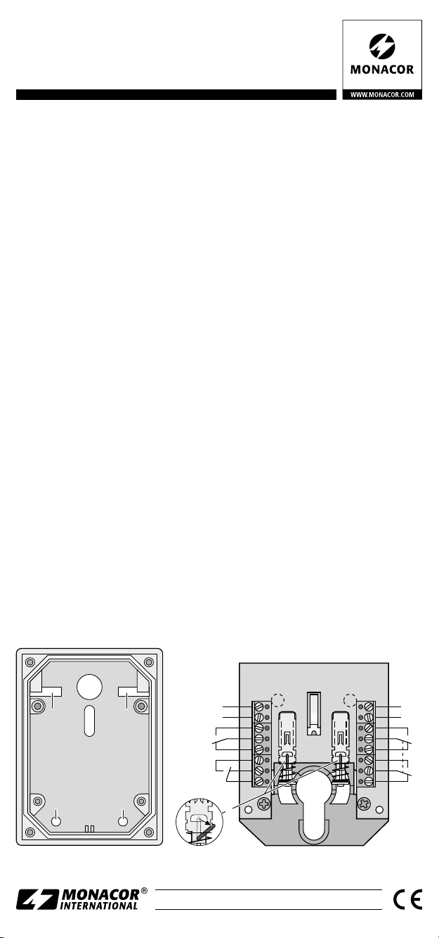
4 Installation
1) Die Frontplatte mithilfe des beiliegenden
Schlüssels abschrauben und abnehmen.
Die beiden Schrauben links und rechts
unten, welche die Leiterplatte halten,
entfernen und die Leiterplatte herausnehmen.
2) An geeigneter Stelle die Befestigungslöcher (a) anzeichnen und bohren. Die
Anschlusskabel durch die Öffnung (b)
führen und das Gehäuse festschrauben.
3) Sollen die Schalter (S1, S2) als Taster arbeiten, den zugehörigen Bügel (c) einseitig aushängen.
4) Bei dem Modell NSA-80 einen Schließzylinder einsetzen und festschrauben.
5) Die Schalter (S1, S2), Sabotagekontakte (K1) und LEDs wie erforderlich
an schließen.
6) Die Leiterplatte wieder in das Gehäuse
einsetzen und festschrauben. Die Frontplatte festschrauben.
5 Technische Daten
Kontakte: . . . . . . . . . . . . . 1-polig und
Kontaktbelastung:
LED-Betriebsspannung: . . . ⎓ 12 V
Gehäusemaße: . . . . . . . . . 88 × 118 ×
2-polig um
. . . . . . ⎓ 30 V, 0,5 A
50 mm
4 Installation
1) Unscrew the front panel by means of
the supplied wrench and remove it.
Remove the two screws on the left and
right at the bottom which hold the PCB
and remove the PCB.
2) Mark the fastening holes (a) at a suitable
place and drill them. Guide the connection cables through the opening (b) and
fasten the housing with screws.
3) To operate the switches (S1, S2) as
momentary action pushbuttons, detach one side of the corresponding
bracket(c).
4) Model NSA-80: Insert a lock cylinder
and fasten it with a screw.
5) Connect the switches (S1, S2), anti-tamper contacts (K1) and LEDs as required.
6) Insert the PCB into the housing and fasten it with screws. Fasten the front panel
with screws.
5 Specifications
Contacts: . . . . . . . . . . . . . 1-pole and
Contact rating:
Operating voltage of LED: . ⎓ 12 V
Dimensions of housing: . . . 88 × 118 ×
. . . . . . . . . ⎓ 30 V, 0.5 A
2-pole, selector switch
50 mm
Änderungen vorbehalten.
b
a
a
a a
Subject to technical modifications.
K 1
LED 2
S 2S 1
LED1
S1
K1
LED 1
+
12V
-
c
Copyright © by MONACOR INTERNATIONAL. All rights reserved.
A-0993.99.04.02.2019
12V
+
LED2
-
S2
Page 3

NSA-80 Référence num. • Codice 04.1080
NSA-90 Référence num. • Codice 04.1060
ELECTRONICS FOR SPECIALISTS ELECTRONICS FOR SPECIALISTS ELECTRONICS FOR SPECIALISTS
Interrupteur à clé
Cette notice s’adresse aux installateurs
avec des connaissances techniques en
alarme et surveillance. Veuillez lire la
Français
présente notice avec attention avant
l’installation et conservez-la pour pouvoir vous y reporter ultérieurement.
1 Possibilités d’utilisation
L’interrupteur à clé permet une commande
à distance des installations d’alarme et de
surveillance, de gestion de porte et autres
applications de commutation. En tournant
vers la droite la clé, un sélecteur 2 pôles est
activé, en tournant vers la gauche, un sélecteur un pôle. Les interrupteurs sont commutables séparément sur la fonction momentanée. Via deux LEDs, on peut afficher les
ordres de commutation exécutés. Grâce à
des contacts anti-sabotage, on peut surveiller toute ouverture non autorisée du boîtier
et l’arrachement du lieu de montage.
2 Accessoires livrés
1 cylindre de fermeture avec 3 clés
(uniquement sur le modèle NSA-90)
4 vis Torx pour la face avant et
une clé appropriée
4 chevilles 6 mm
4 vis de fixation, 4,5 × 35 mm
3 Conseils d’utilisation
L’interrupteur à clé répond à toutes les directives nécessaires de l’Union européenne
et porte donc le symbole
L’interrupteur n’est conçu que pour une
•
utilisation en intérieur, protégez-le des
éclaboussures, de tout type de projec-
tions d’eau, d’une humidité élevée et
l’air et de la chaleur (plage de tempéra-
ture autorisée 0 – 40 °C).
Pour nettoyer le boîtier, utilisez un chif-
•
fon doux, éventuellement légèrement
humidifié, en aucun cas, un produit de
nettoyage agressifs.
Nous déclinons toute responsabilité en
•
cas de dommages corporels ou matériels
résultants si l’interrupteur à clé est utilisé
dans un but autre que celui pour lequel
il a été conçu, s’il n’est pas correctement
monté ou s’il n’est pas réparé par une
personne habilitée ; en outre, la garantie
deviendrait caduque.
Lorsque l’interrupteur est définitivement retiré du service, vous devez
le déposer dans une usine de recyclage de proximité pour contribuer
à son élimination non polluante.
.
MONACOR INTERNATIONAL GmbH & Co. KG
Zum Falsch 36 • 28307 Bremen • Germany
Interruttore a chiave
Queste istruzioni sono rivolte agli installatori con relative conoscenze nella
Italiano
tecnica della allarme e sorveglianza.
Vi preghiamo di leggere attentamente
le presenti istruzioni prima dell’installazione e di conservarle per un uso
futuro.
1 Possibilità d’impiego
L’interruttore a chiave serve per telecomandare impianti d’allarme e di sorveglianza,
l’apertura e la chiusura di portoni e altri
compiti simili. Girando la chiave a destra si
aziona un commutatore a due poli, girandola a sinistra si aziona un commutatore
a un polo. Gli interruttori possono essere
modificati per assumere la funzione di pulsanti. Tramite due LED si segnalano i comandi eseguiti. L’apertura non autorizzata
del contenitore e lo strappo dal punto di
montaggio possono essere controllati da
contatti antisabotaggio.
2 Accessori in dotazione
1 cilindro di chiusura con 3 chiavi
(solo con il modello NSA-90)
4 viti Torx per il pannello frontale e
1 chiave adatta
4 tasselli da muro, 6 mm
4 viti di fissaggio, 4,5 × 35 mm
3 Avvertenze importanti per l’uso
L’interruttore a chiave è conforme a tutte le
direttive rilevanti dell’UE e pertanto porta
la sigla
•
•
•
.
Usare l’interruttore a chiave solo all’interno di locali e proteggerlo dall’acqua
gocciolante e dagli spruzzi d’acqua, da
alta umidità dell’aria e dal calore (temperatura d’impiego ammessa fra 0 e 40 °C).
Per la pulizia del contenitore usare solo
un panno morbido, eventualmente inumidito; non impiegare in nessun caso
detergenti aggressivi.
Nel caso d’uso improprio, d’installazione
sbagliata o di riparazione non a regola
d’arte dell’interruttore a chiave, non si
assume nessuna responsabilità per eventuali danni consequenziali a persone o a
cose e non si assume nessuna garanzia
per l’apparecchio.
Se si desidera eliminare l’interruttore a chiave definitivamente,
consegnarlo per lo smaltimento
ad un’istituzione locale per il
riciclaggio.
Page 4

NSA-80
NSA-90
ELECTRONICS FOR SPECIALISTS ELECTRONICS FOR SPECIALISTS ELECTRONICS FOR SPECIALISTS
4 Installation
1) Dévissez la plaque avant avec la clé
livrée et retirez-la. Retirez les deux vis à
gauche et à droite qui maintiennent la
platine et retirez la platine.
2) Dessinez les trous de fixation (a) à l’endroit voulu et percez. Faites passer les
câbles de branchement via l’ouverture
(b) et revissez le boîtier.
3) Pour faire fonctionner les interrupteurs
(S1, S2) comme boutons poussoirs momentanés, détachez un côté de l’étrier
correspondant (c).
4) Sur le modèle NSA-80, placez un cylindre
de fermeture et vissez.
5) Reliez les interrupteurs (S1, S2), les
contacts anti-sabotage (K1) et les LEDs
comme nécessaire.
6) Replacez la platine dans le boîtier et
revissez. Revissez la face avant.
5 Caractéristiques techniques
Contacts : . . . . . . . . . . . . . sélecteur
Charge contact :
. . . . . . . . ⎓ 30 V, 0,5 A
Tension fonctionnement
. . . . . . . . . . . . . . . . . ⎓ 12 V
LED :
Dimensions boîtier : . . . . . 88 × 118 ×
Tout droit de modification réservé.
1pôle et
2pôles
50 mm
4 Installazione
1) Svitare il pannello frontale per mezzo
della chiave in dotazione e staccarla.
Togliere le due viti a destra e a sinistra
che tengono fermo il circuito stampato
e staccare il circuito stampato.
2) In un posto adatto segnare i fori di fissaggio (a) e eseguire i fori. Far passare
i cavi di collegamento attraverso l’apertura (b) e avvitare il contenitore.
3) Se gli interruttori (S1, S2) devono funzionare come pulsanti, sganciare la relativa staffa (c) da un lato.
4) Per il modello NSA-80 inserire un cilindro di chiusura e avvitarlo.
5) Collegare come necessario gli interruttori (S1, S2), i contatti antisabotaggio
(K1) e i LED.
6) Rimettere il circuito stampato nel contenitore e avvitarlo. Avvitare il pannello
frontale.
5 Dati tecnici
Contatti: . . . . . . . . . . . . . . 1 polo e
Potenza dei contatti: . . . . . ⎓ 30 V, 0,5 A
Tensione d’esercizio
. . . . . . . . . . . . . . ⎓ 12 V
dei LED:
Dimensioni de
contenitore:
Con riserva di modifiche tecniche.
. . . . . . . . . . . 88 × 118 ×
2poli, ON / ON
50 mm
CARTONS ET EMBALLAGE
PAPIER À TRIER
b
a
a a
K 1
LED 1
+
LED1
12V
a
-
S1
K1
c
Copyright © by MONACOR INTERNATIONAL. All rights reserved.
A-0993.99.04.02.2019
S 2S 1
LED 2
12V
+
LED2
-
S2
 Loading...