

Page 1
MOUSE-09
3
105
ELECTRONICS FOR SPECIALISTS ELECTRONICS FOR SPECIALISTS ELECTRONICS FOR SPECIALISTS ELECTRONICS FOR SPECIALISTS ELECTRONICS FOR SPECIALISTS ELECTRONICS
Bestellnummer 04.7150
Dual-Bewegungsmelder
Diese Anleitung richtet sich an Installateure mit
Fachkenntnissen in der Alarmtechnik. Bitte lesen
Sie die Anleitung vor der Installation gründlich
Deutsch
durch und heben Sie sie für ein späteres Nachlesen auf.
1 Einsatzmöglichkeiten
Der Dual-Bewegungsmelder MOUSE-09 mit Mikroprozessorsteuerung ist speziell für den Einsatz in
Alarm- und Video-Überwachungsanlagen konzipiert.
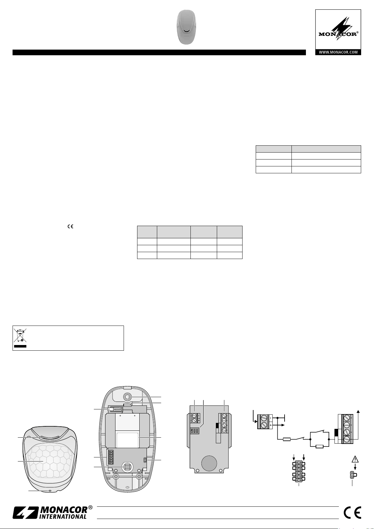
Er kombiniert einen IR-Melder (6) und einen Mikrowellenmelder (9) und ist dadurch auch für die Sicherung problematischer Räume geeignet (z. B. Bereiche
mit Zugluft). Bei einer erkannten Bewegung öffnet
der NC-Alarmkontakt (normally closed = Öffner).
Zum Schutz des Melders ist ein Sabotagekontakt (4)
vorhanden, der beim Öffnen des Gehäuses einen
Alarm über die Alarmzentrale auslöst.
Der Alarm- und der Sabotagekontakt können
entweder separat an die Alarmzentrale angeschlossen
werden oder in Reihe geschaltet mit wählbaren Reihenund Parallelwiderständen als Differenzial- Meldelinie.
2 Wichtige Hinweise für den Gebrauch
Der Melder entspricht allen relevanten Richtlinien der
EU und trägt deshalb das
Verwenden Sie den Melder nur im Innenbereich
•
und schützen Sie ihn vor Tropf- und Spritzwasser
sowie vor hoher Luftfeuchtigkeit. Die zulässige Einsatztemperatur beträgt −10 bis +55 °C.
Berühren Sie bei geöffnetem Gehäuse auf keinen
•
Fall die Oberfläche des IR-Sensors (6); dieser kann
dadurch beschädigt werden.
Verwenden Sie zum Reinigen nur ein trockenes,
•
weiches Tuch, niemals Chemikalien oder Wasser.
Wird der Melder zweckentfremdet, falsch instal-
•
liert oder nicht fachgerecht repariert, kann keine
Haftung für daraus resultierende Sach- oder Personenschäden und keine Garantie für den Melder
übernommen werden.
Soll der Melder endgültig aus dem Betrieb
genommen werden, übergeben Sie ihn zur
umweltgerechten Entsorgung einem örtlichen Recyclingbetrieb.
-Zeichen.
3 Installation
3.1 Montage
Die empfohlene Montagehöhe beträgt 2 m.
•
Der Montageort sollte frei von Erschütterungen und
•
direkter Sonneneinstrahlung sein und sich nicht in der
Nähe von Wärmequellen (z. B. Heizung) befinden.
Die Montagestelle so wählen, dass sich die Alarm
•
auslösende Person quer zur Linse (2) bewegt.
1) Zum Öffnen des Gehäuses die Abdeckung entriegeln: Einen Schraubendreher in das Loch (3) unten
am Gehäuse stecken.
2) Die Montage kann direkt flach an der Wand oder
in einer Zimmerecke erfolgen oder über den als
Zubehör erhältlichen schwenkbaren Halter SN-1.
Die für die Befestigung benötigten Durchbruchstellen am Gehäuserückteil aufbohren. Damit
diese zugängig sind, die Platine herausnehmen
[die Rastnase (8) vorsichtig nach oben drücken].
3) Die Durchbruchstelle (7) für die Anschlusskabel
aufbohren. Die Kabel durch die Bohrung und ggf.
durch die Halterung in das Gehäuse führen. Die
Gehäuserückseite an der Halterung oder Wand
festschrauben.
3.2 Einstellungen und Anschluss
1) Die DIP-Schalter (12) den Erfordernissen entsprechend einstellen:
Schalter-
Nr.
Funktion
1 Kontroll-LED (1) an aus
2 Alarm bei 2 Impulsen 1 Impuls
3 Reichweite
2) Vor dem Anschluss die Alarmzentrale außer Betrieb setzen, damit kein Alarm ausgelöst werden
kann. Dann die Zentrale an die Schraubklemmen
(13) anschließen:
Alarm- und Sabotagekontakt separat:
–
Alarmkontakt = Klemmen „N.C.“
Sabotagekontakt = Klemmen „TAMPER“
Alarm- und Sabotagekontakt als Differenzial-
–
Meldelinie (Abb. 4): Klemme „EOL“
Auf die Pins Position 10 eine Steckbrücke setzen. Die Werte für die Widerstände R1 und R2
durch Setzen von Steckbrücken auf die Pins Position 5 nach der Abb. 4 wählen.
3) Die 12-V-Gleichspannung an die Klemmen + − (11)
anschließen.
Position ONPosition
OFF
15 m 7 m
3.3 Funktionstest
1) Zur Funktionskontrolle den DIP-Schalter Nr. 1 auf
ON stellen, damit die Kontroll-LED (1) bei einer
erkannten Bewegung aufleuchtet. Die Platine
wieder einsetzen. Den Melder mit dem Gehäusedeckel schließen (den Deckel oben einhaken und
zudrücken, bis er unten einrastet) und die Stromversorgung einschalten. Nach einer Minute hört
die Kontroll-LED auf zu blinken und der Melder
ist betriebsbereit.
2) Den Überwachungsbereich in verschiedenen Richtungen durchqueren und dabei die Kontroll-LED
beobachten, die bei einer erkannten Bewegung
aufleuchtet:
LED Bedeutung
leuchtet grün Mikrowellensensor spricht an
leuchtet orange IR-Sensor spricht an
leuchtet rot Alarmkontakt öffnet
3) Bei Bedarf mit dem DIP-Schalter Nr. 3 die Einstellung der Reichweite ändern und mit dem DIPSchalter Nr. 2 den Bewegungszähler: Wenn bei
einer einzelnen Bewegungserkennung ein Alarm
ausgelöst werden soll, den Schalter auf OFF stellen.
Damit erst bei zwei innerhalb von 5 s erkannten
Bewegungen ein Alarm ausgelöst wird, den Schalter auf ON stellen. Dies reduziert die Wahrscheinlichkeit eines Fehlalarms durch kleinere Objekte.
4) Nach der Funktionskontrolle den DIP-Schalter Nr. 1
auf OFF stellen, damit die Kontroll-LED bei einer
erkannten Bewegung nicht aufleuchtet und der
Erfassungsbereichs bei unscharfer Alarmzentrale
nicht ausspioniert werden kann.
5) Abschließend einen Funktionstest mit scharf geschalteter Alarmzentrale durchführen.
4 Technische Daten
Reichweite: . . . . . . . . . . . . . . . . .max. 15 m
Erfassungswinkel: . . . . . . . . . . . .90° (±45°)
Alarmkontakt:
Belastbarkeit: . . . . . . . . . . . . . .max. 100 mA / 40 V (⎓)
Innenwiderstand: . . . . . . . . . . .16 Ω
Alarmzeit: . . . . . . . . . . . . . . . . .2 s
Sabotagekontakt: . . . . . . . . . . . .Öffner (NC)
Belastbarkeit: . . . . . . . . . . . . . .max. 40 mA / 30 V (⎓)
Gleichspannungsversorgung:
Stromverbrauch / Ruhestrom: . . .24 / 17 mA bei 13,8 V
Mikrowellenfrequenzen: . . . . . . . .9,3 / 9,9 / 10,525 GHz
Schutz gegen HF-Störungen: . . . .30 V/ m (80 – 2000 MHz)
Einsatztemperatur: . . . . . . . . . . . .−10 bis +55 °C
Gehäuseschutzart: . . . . . . . . . . . .IP 30
Abmessungen, Gewicht: . . . . . . . .60 × 110 × 46 mm, 75 g
. . . . . . . . . . . . . . .Öffner (NC)
. . . .9 – 15 V
1
2
Ansicht von vorn unten
➀
Änderungen vorbehalten.
7
4
AS715617
04-0037-2815-Y
C915617
5
6
Innenansicht
➁
MONACOR INTERNATIONAL GmbH & Co. KG • Zum Falsch 36 • 28307 Bremen • Germany
Copyright
©
by MONACOR INTERNATIONAL. All rights reserved.
8
9
10
11 12 13
ON
1 2 3
Rückseite Leiterplatte
➂
EOL
12 V
TAMPERN.C.
FAULT
Konfiguration Differenzial-Meldelinie
➃
+12 V
Tamper
R1
R1
2k2
5k6
4k7
1k
A-1657.99.01.04.2016
R 2
2k2
5k6
4k7
2k2
Alarm
R 2
Alarmzentrale
TAMPERN.C.
EOL
Page 2
MOUSE-09
3
105
ELECTRONICS FOR SPECIALISTS ELECTRONICS FOR SPECIALISTS ELECTRONICS FOR SPECIALISTS ELECTRONICS FOR SPECIALISTS ELECTRONICS FOR SPECIALISTS ELECTRONICS
Order number 04.7150
Dual Motion Detector
These instructions are intended for installers
with specific knowledge in alarm technology.
English
Please read the instructions carefully prior to
operation and keep them for later reference.
1 Applications
The dual motion detector MOUSE-09 with microprocessor control is specially designed for alarm and
video surveillance systems. It combines an IR detector
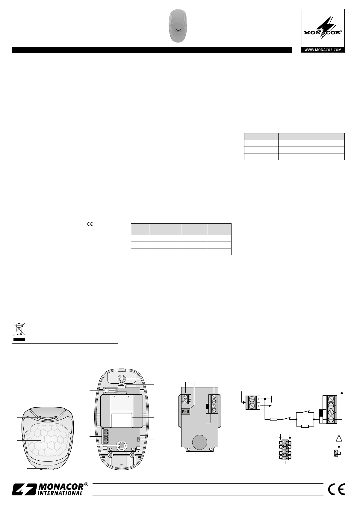
(6) and a microwave detector (9) and is therefore also
suitable for premises where security conditions are
difficult (e. g. areas subject to draught). When movement has been detected, the NC (normally closed)
alarm contact will open. As a precaution, the motion
detector is provided with an anti-tamper contact
(4) which will trigger an alarm via the alarm control
panel when the housing is opened.
The alarm contact and the anti-tamper contact
can either be connected separately to the alarm
control panel or connected in series with selectable
series resistors or parallel resistors as a differential
alarm loop.
2 Important Notes
The detector corresponds to all relevant directives of
the EU and is therefore marked with
The detector is suitable for indoor use only. Protect
•
it against dripping water, splash water and high
air humidity. The admissible ambient temperature
range is −10 to +55 °C.
Never touch the surface of the IR sensor (6) when
•
the housing is open; the sensor may be damaged.
For cleaning only use a dry, soft cloth; never use
•
water or chemicals.
No guarantee claims for the detector and no liabil-
•
ity for any resulting personal damage or material
damage will be accepted if the detector is used
for other purposes than originally intended, if it is
not correctly installed, or if it is not repaired in an
expert way.
If the detector is to be put out of operation
definitively, take it to a local recycling plant
for a disposal which is not harmful to the
environment.
.
4
3 Installation
3.1 Installing the motion detector
The recommended installation height is 2 m.
•
Do not install the motion detector in places where
•
it is exposed to vibrations or direct sunlight or
where it is close to heat sources (e. g. radiators).
Find a place of installation where an alarm will be
•
triggered when a person moves at right angles to
the lens (2).
1) Open the housing: To unlock the cover, insert a
screwdriver into the hole (3) at the bottom of the
housing.
2) The motion detector can be installed flat on a wall
or in a corner. Alternatively, use the movable support SN-1 available as accessory. Blind holes for
installation are provided on the rear of the housing. Use a drill to open these holes. To access the
holes, remove the PCB [carefully push the latch
(8) upwards].
3) Use a drill to open the blind hole (7) for the connection cables. Lead the cables through the hole
and, if necessary, though the support into the
housing. Fasten the rear side of the housing to
the support or to a wall.
3.2 Settings and connection
1) Set the DIP switches (12) according to the requirements:
Switch
No.
Function
1 indicator LED (1) on off
2 alarm after 2 pulses 1 pulse
3 range
2) Before connecting, put the alarm control panel
out of operation so that no alarm will be triggered. Then connect the alarm control panel to
the screw terminals (13):
alarm contact and anti-tamper contact sepa-
–
rately:
alarm contact = terminals “N.C.”
anti-tamper contact = terminals “TAMPER”
alarm contact and anti-tamper contact as a dif-
–
ferential alarm loop
Place a jumper on the pins of position 10. Place
jumpers on the pins of position 5 to define the values for the resistors R1 and R2 according to fig. 4.
3) Connect the 12 V DC voltage to the terminals
+− (11).
7
8
Position ONPosition
OFF
15 m 7 m
(fig. 4): terminal “EOL”
11 12 13
3.3 Functional test
1) For a functional test, set DIP switch No. 1 to ON
so that the indicator LED (1) will light up when
movement has been detected. Insert the PCB.
Close the cover of the motion detector (hook the
cover into the latch at the top and close the cover
until it engages at the bottom) and switch on the
power supply. After one minute, the indicator LED
will stop flashing: The motion detector is ready
for operation.
2) Walk through the surveillance zone in different directions while observing the indicator LED which will
light up whenever movement has been detected:
LED Meaning
green microwave sensor responds
orange IR sensor responds
red alarm contacts opens
3) If required, use DIP switch No. 3 to change the
settings for the range and DIP switch No. 2 to
change the pulse count: To trigger an alarm when
a single movement has been detected, set the
switch to OFF. To trigger an alarm only after two
movements have been detected within 5 seconds,
set the switch to ON. This will reduce the probability of false alarms caused by small objects.
4) After the functional test, set DIP switch No. 1 to
OFF so that the indicator LED will not light up
when movement has been detected. Thus, any
intruder will not be able to spy out the coverage
area when the alarm control panel is disarmed.
5) Finally, make a functional test when the alarm
control panel is armed.
4 Specifications
Detection range: . . . . . . . . . . . . .15 m max.
Detection angle: . . . . . . . . . . . . .90° (± 45°)
Alarm contact:
Power rating: . . . . . . . . . . . . . .100 mA / 40 V (⎓) max.
Internal resistance: . . . . . . . . . .16 Ω
Alarm time: . . . . . . . . . . . . . . .2 s
Anti-tamper contact:
Power rating: . . . . . . . . . . . . . .40 mA /30 V (⎓) max.
DC power supply:
Power consumption: . . . . . . . . .24 mA at 13.8 V
Quiescent current: . . . . . . . . . . .17 mA at 13.8 V
Microwave frequencies: . . . . . . . .9.3 / 9.9 /10.525 GHz
Protection against RF interference: 30 V/ m (80 – 2000 MHz)
Ambient temperature: . . . . . . . . .−10 to +55 °C
Protection of housing: . . . . . . . . .IP 30
Dimensions, weight: . . . . . . . . . . .60 × 110 × 46 mm, 75 g
Subject to technical modification.
12 V
. . . . . . . . . . . . . . .normally closed (NC)
contact
. . . . . . . . . .normally closed (NC)
contact
. . . . . . . . . . . .9 – 15 V
alarm control panel
1
2
Front view from below
➀
TAMPERN.C.
ON
AS715617
04-0037-2815-Y
C915617
5
6
Inside view
➁
MONACOR INTERNATIONAL GmbH & Co. KG • Zum Falsch 36 • 28307 Bremen • Germany
Copyright
©
by MONACOR INTERNATIONAL. All rights reserved.
9
10
1 2 3
Rear view of PCB
➂
EOL
FAULT
Configuration of differential alarm loop
➃
+12 V
Tamper
R1
R1
2k2
5k6
4k7
1k
A-1657.99.01.04.2016
R 2
2k2
5k6
4k7
2k2
Alarm
R 2
TAMPERN.C.
EOL
Page 3
MOUSE-09
3
105
ELECTRONICS FOR SPECIALISTS ELECTRONICS FOR SPECIALISTS ELECTRONICS FOR SPECIALISTS ELECTRONICS FOR SPECIALISTS ELECTRONICS FOR SPECIALISTS ELECTRONICS
Référence numerique 04.7150
Détecteur double de mouvements
Cette notice s’adresse aux installateurs avec des
connaissances de base en technologie d‘alarme.
Veuillez lire la présente notice avec attention
Français
avant l‘installation et conservez-la pour pouvoir
vous y reporter ultérieurement.
1 Possibilités d‘utilisation
Le détecteur de mouvements double MOUSE-09
avec gestion par micro-processeur est spécialement
conçu pour une utilisation dans des installations
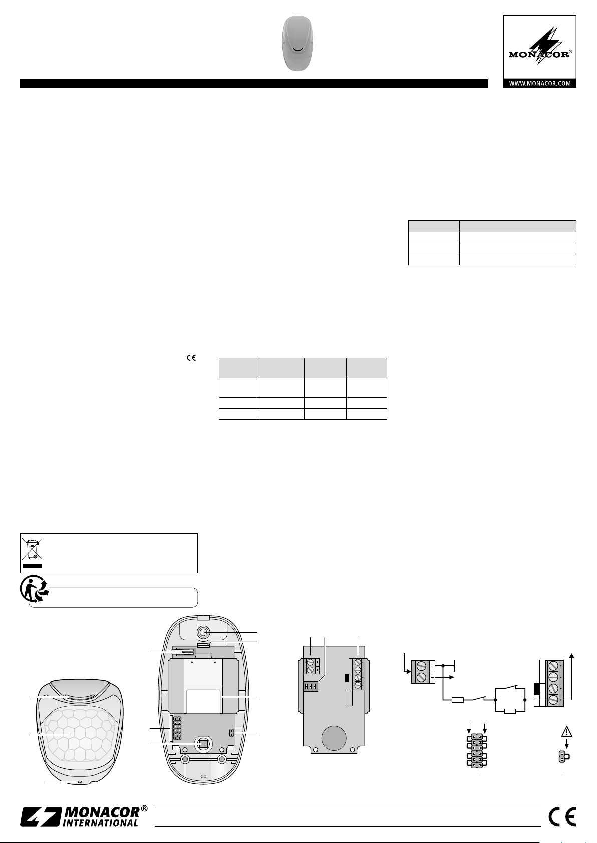
d‘alarme et de surveillance vidéo ; il combine un détecteur infrarouge (6) et un détecteur de micro-ondes
(9) et est ainsi adapté également pour la surveillance
de pièces problématiques (par exemple zones avec
courants d‘air). Si un mouvement est détecté, le
contact N.C. (normally closed = ouverture) s‘ouvre.
Le contact anti-sabotage (4) protège le détecteur :
lorsque le boîtier est ouvert, le contact anti-sabotage
déclenche une alarme via la centrale d‘alarme.
Les contacts anti-sabotage et d‘alarme peuvent
être reliés soit séparément à la centrale d‘alarme soit
en série avec résistances série et parallèles sélectionnables comme boucle d‘alarme différentielle.
2 Conseils importants d’utilisation
Le détecteur répond à toutes les directives nécessaires
de l’Union européenne et porte donc le symbole
Le détecteur n‘est conçu que pour une utilisation
•
en intérieur. Protégez-le des éclaboussures, de tout
type de projections d‘eau et d’une humidité élevée
de l‘air ; la plage de température ambiante admissible est de −10 à +55 °C.
Ne touchez jamais la surface du capteur infrarouge
•
(6) lorsque le boîtier est ouvert ; le capteur pourrait
être endommagé.
Pour le nettoyage, utilisez uniquement un chiffon
•
sec et doux, en aucun cas de produits chimiques
ou d‘eau.
Nous déclinons toute responsabilité en cas de dom-
•
mages matériels ou corporels résultants si le détecteur est utilisé dans un but autre que celui pour
lequel il a été conçu, s‘il n‘est pas correctement installé ou s‘il n‘est pas réparé par une personne qualifiée ; en outre, la garantie deviendrait caduque.
Lorsque le détecteur est définitivement retiré du service, vous devez le déposer dans
une usine de recyclage adaptée pour contribuer à son élimination non polluante.
CARTONS ET EMBALLAGE
PAPIER À TRIER
4
3 Installation
3.1 Montage
La hauteur de montage conseillée est de 2 m.
•
Le lieu de montage ne devrait pas être soumis à des
•
vibrations et à la lumière directe du soleil ; de plus,
il ne devrait pas se trouver à proximité de sources
de chaleur (par exemple chauffage).
Sélectionnez le lieu de montage de telle sorte qu‘une
•
alarme soit déclenchée lorsqu‘une personne se déplace transversalement par rapport à la lentille (2).
1) Pour ouvrir le boîtier, déverrouillez le couvercle: placez un tournevis dans le trou (3) en bas du boîtier.
2) Le montage peut se faire directement à plat sur un
mur ou dans un angle de pièce ou via le support
SN-1 orientable, disponible en option. Percez les
emplacements nécessaires pour la fixation prévus
sur la partie arrière du boîtier ; vous pouvez retirer
la platine pour qu‘ils soient accessibles [poussez la
languette (8) légèrement vers le haut].
3) Percez l‘emplacement (7) prévu pour les câbles
de branchement. Faites passer les câbles dans le
boîtier via l‘ouverture et, si besoin, via le support
et vissez la face arrière du boîtier au mur ou sur
le support.
3.2 Réglages et branchement
1) Réglez les interrupteurs DIP (12) selon les besoins :
.
Numéro
interrupteur
1
Fonction
LED de
contrôle (1)
Position ONPosition
marche arrêt
2 Alarme après 2 impulsions 1 impulsion
3 Portée
15 m 7 m
2) Avant de brancher le détecteur, mettez la centrale
d‘alarme hors fonction pour éviter tout déclenchement d‘alarme. Ensuite, reliez la centrale aux
bornes à vis (13) :
–
contacts alarme et anti-sabotage, séparés :
contact alarme = bornes «N.C.»
contact anti-sabotage = bornes “TAMPER“
–
contacts alarme et anti-sabotage comme
boucle d‘alarme différentielle (schéma 4) :
borne «EOL»
Mettez un cavalier sur les pins de position 10.
Sélectionnez les valeurs pour les résistances R1
et R2 en mettant les cavaliers sur les pins de
position 5, selon le schéma 4.
3) Reliez la tension continue 12 V aux bornes + − (11).
7
8
11 12 13
OFF
3.3 Test de fonctionnement
1) Pour contrôler le fonctionnement, mettez l‘interrupteur DIP N°1 sur ON : la LED de contrôle (1) brille
lorsqu‘un mouvement est détecté. Replacez la platine. Fermez le détecteur avec le couvercle du boîtier (enclenchez le couvercle par le haut et appuyez
jusqu‘à ce qu‘il s‘enclenche en bas) et allumez l‘alimentation. Après une minute, la LED de contrôle
ne clignote plus, le détecteur est prêt à fonctionner.
2) Traversez la zone de surveillance dans différentes
directions et observez le comportement de la LED
de contrôle ; elle brille lorsqu‘un mouvement est
détecté :
LED Signification
brille en vert le détecteur de micro-ondes déclenche
brille en orange le détecteur IR déclenche
brille en rouge le contact d‘alarme s‘ouvre
3) Si besoin, modifiez le réglage de la portée avec
l‘interrupteur DIP N°3 et le compteur de mouvements avec l‘interrupteur N°2 : Pour déclencher
une alarme si un seul mouvement est détecté,
mettez l‘interrupteur sur OFF. Pour déclencher
une alarme uniquement si deux mouvements sont
détectés en l‘espace de 5 secondes, mettez l‘interrupteur sur ON. Cela diminue la possibilité d‘une
fausse alarme déclenchée par de petits objets.
4) Après le contrôle de fonctionnement, mettez l‘interrupteur DIP N° 1 sur OFF pour que la LED de
contrôle ne brille plus si un mouvement est détecté; ainsi, la zone de surveillance ne peut pas être
espionnée si la centrale d‘alarme est désactivée.
5) Enfin, effectuez un test de fonctionnement avec
la centrale d‘alarme activée.
4 Caractéristiques techniques
Portée : . . . . . . . . . . . . . . . . . . . .15 m max.
Angle de détection : . . . . . . . . . . .90° (±45°)
Contact d‘alarme :
Puissance : . . . . . . . . . . . . . . . .100 mA / 40 V (⎓) max.
Résistance interne : . . . . . . . . . .16 Ω
Durée alarme : . . . . . . . . . . . . .2 s
Contact anti-sabotage : . . . . . . . .contact NC
Puissance : . . . . . . . . . . . . . . . .40 mA / 30 V (⎓) max.
Tension de fonctionnement :
Consommation : . . . . . . . . . . . .24 mA à 13,8 V
Courant de repos : . . . . . . . . . .17 mA à 13,8 V
Fréquences micro-ondes : . . . . . . .9,3 / 9,9 / 10,525 GHz
Protection contre les
interférences HF :
Température fonc. : . . . . . . . . . . .−10 à +55° C
Type protection boîtier : . . . . . . . .IP 30
Dimensions, poids : . . . . . . . . . . .60 × 110 × 46 mm, 75 g
Tout droit de modification réservé.
12 V
. . . . . . . . . . . .contact NC
. . . .9 à 15 V
. . . . . . . . . . . . .30 V/m (80 – 2000 MHz)
centrale d‘alarme
1
2
Vue avant du dessous
➀
TAMPERN.C.
ON
AS715617
04-0037-2815-Y
C915617
5
6
Vue intérieure
➁
MONACOR INTERNATIONAL GmbH & Co. KG • Zum Falsch 36 • 28307 Bremen • Germany
Copyright
©
by MONACOR INTERNATIONAL. All rights reserved.
9
10
1 2 3
Face arrière platine
➂
EOL
FAULT
Configuration boucle d‘alarme différentielle
➃
+12 V
Tamper
R1
R1
2k2
5k6
4k7
1k
A-1657.99.01.04.2016
R 2
2k2
5k6
4k7
2k2
Alarm
R 2
TAMPERN.C.
EOL
Page 4
MOUSE-09
3
105
ELECTRONICS FOR SPECIALISTS ELECTRONICS FOR SPECIALISTS ELECTRONICS FOR SPECIALISTS ELECTRONICS FOR SPECIALISTS ELECTRONICS FOR SPECIALISTS ELECTRONICS
Codice 04.7150
Segnalatore doppio
di movimento
Queste istruzioni sono rivolte agli installatori
Italiano
con conoscenze specifiche nella tecnica degli
allarmi. Vi preghiamo di leggerle attentamente
prima dell‘installazione e di conservarle per un
uso futuro.
1 Possibilità d‘impiego
Il segnalatore doppio di movimento MOUSE-09 comandato da microprocessore è stato realizzato specialmente per l‘impiego in impianti d‘allarme e di
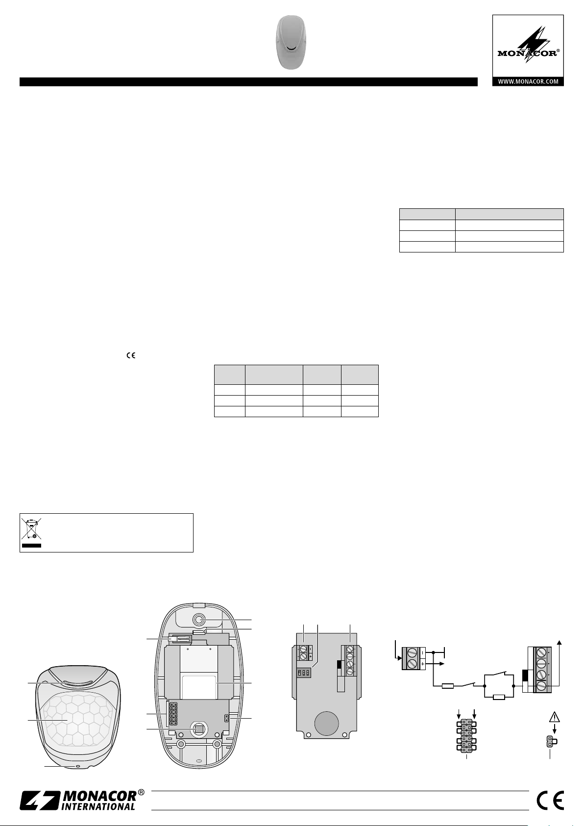
sorveglianza video. È una combinazione fra un segnalatore IR (6) e un segnalatore di microonde (9) e perciò
è adatto anche per proteggere ambienti problematici
(p. es. settori con correnti d‘aria). Se viene rilevato un
movimento, il contatto d‘allarme NC si apre. Come
protezione del segnalatore è presente un contatto
antisabotaggio (4), che fa scattare l‘allarme attraverso
la centralina d‘allarme se il contenitore viene aperto.
I contatti allarme e antisabotaggio possono essere
collegati con la centralina d‘allarme separatamente
oppure collegati in serie come loop differenziale d‘allarme con resistenze a scelta in serie o in parallelo.
2 Avvertenze importanti per l‘uso
Il segnalatore è conforme a tutte le direttive rilevanti
dell’UE e pertanto porta la sigla
Usare il segnalatore solo all’interno di locali e pro-
•
teggerlo dall‘acqua gocciolante e dagli spruzzi
d‘acqua nonché da alta umidità dell‘aria. La temperatura d’esercizio ammessa è −10 a +55 °C).
Se il contenitore è aperto, non toccare in nessun
•
caso la superficie del sensore IR (6) che potrebbe
subire dei danni.
Per la pulizia usare solo un panno morbido,
•
asciutto; non impiegare in nessun caso acqua o
prodotti chimici.
Nel caso d’uso improprio, di installazione scorretta
•
o di riparazione non a regola d’arte del segnalatore,
non si assume nessuna responsabilità per eventuali
danni consequenziali a persone o a cose e non si
assume nessuna garanzia per il segnalatore.
Se si desidera eliminare il segnalatore definitivamente, consegnarlo per lo smaltimento
ad un‘istituzione locale per il riciclaggio.
.
4
3 Installazione
3.1 Montaggio
L‘altezza consigliata per il montaggio è di 2 m.
•
Il posto d’installazione dovrebbe essere libero di
•
scosse e di raggi diretti del sole e non dovrebbe
trovarsi nelle vicinanze di fonti di calore (p. es.
riscaldamento).
Scegliere il posto del montaggio in modo tale che
•
la persona che fa scattare l‘allarme si muove trasversalmente rispetto alla lente (2).
1) Per aprire il contenitore sbloccare la copertura:
inserire un cacciavite nel foro (3) in basso al contenitore.
2) Il montaggio è possibile direttamente alla parete
o in un angolo della camera, ma anche per mezzo
del supporto SN-1 disponibile come accessorio.
Nella parte posteriore del contenitore aprire con
un trapano i punti previsti per il fissaggio. Perché
siano accessibili occorre togliere la scheda [spingere la linguetta (8) delicatamente verso l‘alto].
3) Aprire con un trapano anche il punto previsto
come passacavo (7). Portare i cavi attraverso il
foro e eventualmente anche attraverso il supporto
nel contenitore. Avvitare il retro del contenitore al
supporto o alla parete.
3.2 Impostazioni e collegamento
1) Impostare i dip-switch (12) seconda necessità:
Switch n. Funzione
1 LED di controllo (1) on off
2 Allarme con 2 impulsi 1 impulsi
3 Portata
2) Prima del collegamento mettere fuori funzione la
centralina d‘allarme per escludere degli allarmi.
Quindi collegare la centralina ai morsetti a vite (13):
– contatti d‘allarme e antisabotaggio separata-
mente:
contatto d‘allarme = morsetti “N.C.”
contatto antisabotaggio = morsetti “TAMPER“
– contatti d‘allarme e antisabotaggio come loop
differenziale d‘allarme (fig. 4): morsetto “EOL”
Posizionare un jumper sui pin a posizione 10. I
valori per le resistenze R1 e R2 si determinano
posizionando dei jumper sui pin a posizione 5
come da fig. 4.
3) Collegare la tensione 12 V con i morsetti + − (11).
7
8
Posizione ONPosizione
OFF
15 m 7 m
11 12 13
3.3 Test delle funzioni
1) Per il controllo delle funzioni mettere il dip-switch
n. 1 su ON, affinché il LED di controllo (1) si accenda in caso di un movimento rilevato. Rimettere
la scheda. Chiudere il segnalatore con il coperchio (agganciare il coperchio in alto e spingerlo in
basso fino allo scatto) e attivare l‘alimentazione.
Dopo un minuto, il LED di controllo smette di lampeggiare e il segnalatore è pronto per l‘uso.
2) Attraversare in varie direzioni il settore da sorvegliare e controllare il LED di controllo che si accende in caso di un movimento rilevato:
LED Significato
Acceso verd Reazione del sensore a microonde
Acceso arancione Reazione del sensore IR
Acceso rosso Il contatto d‘allarme si apre
3) Se necessario, con il dip-switch n. 3 modificare l‘impostazione della portata, e con il dip-switch n. 2 il
contatore di movimento: Se con un singolo rilevamento di movimento deve scattare l‘allarme, mettere lo switch su OFF. Affinché l‘allarme scatti solo
se entro 5 secondi vengono rilevati due movimenti,
mettere lo switch su ON. Ciò riduce la probabilità di
un falso allarme scattato da oggetti piccoli.
4) Dopo il controllo delle funzioni mettere il dipswitch n. 1 su OFF perché il LED di controllo non si
accenda in caso di un movimento rilevato e perché
il settore di rilevamento non possa essere individuato con la centralina non attivata.
5) Alla fine effettuare un testo delle funzioni con la
centralina attivata.
4 Dati tecnici
Portata: . . . . . . . . . . . . . . . . . . . .max. 15 m
Angolo di rilevamento: . . . . . . . . .90° (±45°)
Contatto d‘allarme:
Potenza: . . . . . . . . . . . . . . . . . .max. 100 mA / 40 V (⎓)
Resistenza interna: . . . . . . . . . .16 Ω
Durata d‘allarme: . . . . . . . . . . .2 s
Contatto antisabotaggio:
Potenza: . . . . . . . . . . . . . . . . . .max. 40 mA / 30 V (⎓)
Alimentazione con
tensione continua:
Consumo corrente: . . . . . . . . . .24 mA con 13,8 V
corrente di riposo: . . . . . . . . . . .17 mA con 13,8 V
Frequenze microonde: . . . . . . . . .9,3 / 9,9 / 10,525 GHz
Protezione contro
interferenze HF:
Temperatura d‘esercizio:. . . . . . . .−10 a +55 °C
Grado di protezione del
contenitore:
Dimensioni, peso:
Con riserva di modifiche tecniche.
12 V
. . . . . . . . . . .di riposo (NC)
. . . . . . .di riposo (NC)
. . . . . . . . . . . .9 – 15 V
. . . . . . . . . . . . . .30 V/ m (80 – 2000 MHz)
. . . . . . . . . . . . . . . . .IP 30
. . . . . . . . . . . . .60 × 110 × 46 mm, 75 g
centralina d‘allarme
1
2
Vista dal basso davanti
➀
TAMPERN.C.
ON
AS715617
04-0037-2815-Y
C915617
5
6
Vista interna
➁
MONACOR INTERNATIONAL GmbH & Co. KG • Zum Falsch 36 • 28307 Bremen • Germany
Copyright
©
by MONACOR INTERNATIONAL. All rights reserved.
9
10
1 2 3
Retro scheda c. s.
➂
EOL
FAULT
Configurazione loop differenziale d‘allarme
➃
+12 V
Tamper
R1
R1
2k2
5k6
4k7
1k
A-1657.99.01.04.2016
R 2
2k2
5k6
4k7
2k2
Alarm
R 2
TAMPERN.C.
EOL
 Loading...