

Page 1
ELECTRONICS FOR SPECIALISTS ELECTRONICS FOR SPECIALISTS ELECTRONICS FOR SPECIALISTS ELECTRONICS FOR SPECIALISTS
BEDIENUNGSANLEITUNG
INSTRUCTION MANUAL
MODE D’EMPLOI
ISTRUZIONI PER L’USO
MANUAL DE INSTRUCCIONES
VEILIGHEIDSVOORSCHRIFTEN
SIKKERHEDSOPLYSNINGER
SÄKERHETSFÖRESKRIFTER
TURVALLISUUDESTA
Aktive Stereo-Frequenzweiche
für Subwoofer
Active Stereo Crossover Network
for Subwoofer
MCX-200/SW
Bestell-Nr. • Order No. 24.4170
Page 2
2
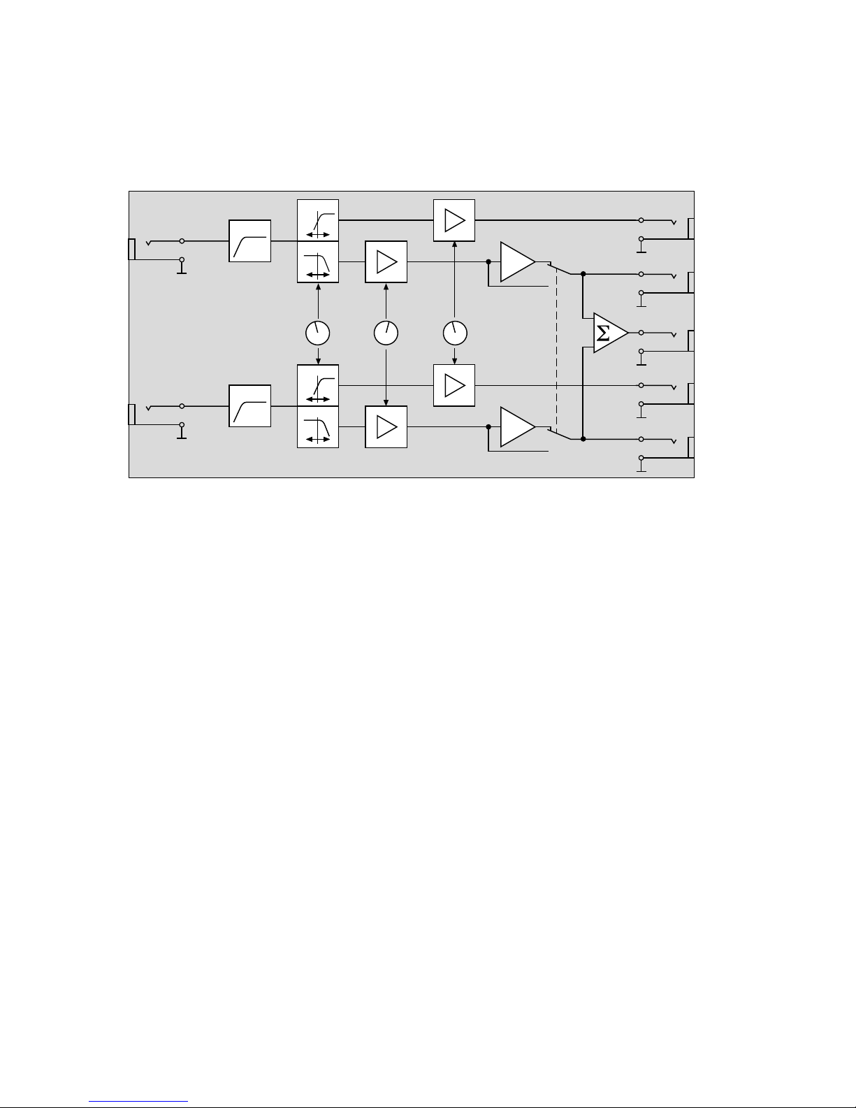
INPUT L
15 Hz
HP-FILTER
-1
SATELLITE
OUTPUT L
SUBWOOFER
OUTPUT L
INPUT R
15 Hz
HP-FILTER
HP-FILTER
LP-FILTER
-1
SATELLITE
OUTPUT R
SUBWOOFER
OUTPUT R
CROSSOVER
FREQUENCY
60...500 Hz
SUBWOOFER
LEVEL
SATELLITE
LEVEL
SUBWOOFER
MONO OUTPUT
HP-FILTER
LP-FILTER
PHASE
REVERSAL
Blockschaltbild
Block diagram
Page 3

ELECTRONICS FOR SPECIALISTS ELECTRONICS FOR SPECIALISTS ELECTRONICS FOR SPECIALISTS ELECTRONICS FOR SPECIALISTS
3
Deutsch ...........Seite 4
English ............Page 5
Français ...........Page 6
Italiano............Pagina 7
Español ...........Página 8
Nederlands ........Pagina 10
Dansk .............Sida 10
Svenska ...........Sidan 11
Suomi.............Sivulta 11
Page 4
4
Deutsch
MCX-2 00/SW
POWER
NORMAL
REVERSE
60
220
100 350
Hz 500
SUBWOOFER
PHASE
CROSSOVER FREQUENCYSUBWOOFER
OUTPUT
-
10 dB +10
LEVEL
SATELLITE
OUTPUT
-
10 dB +10
LEVEL
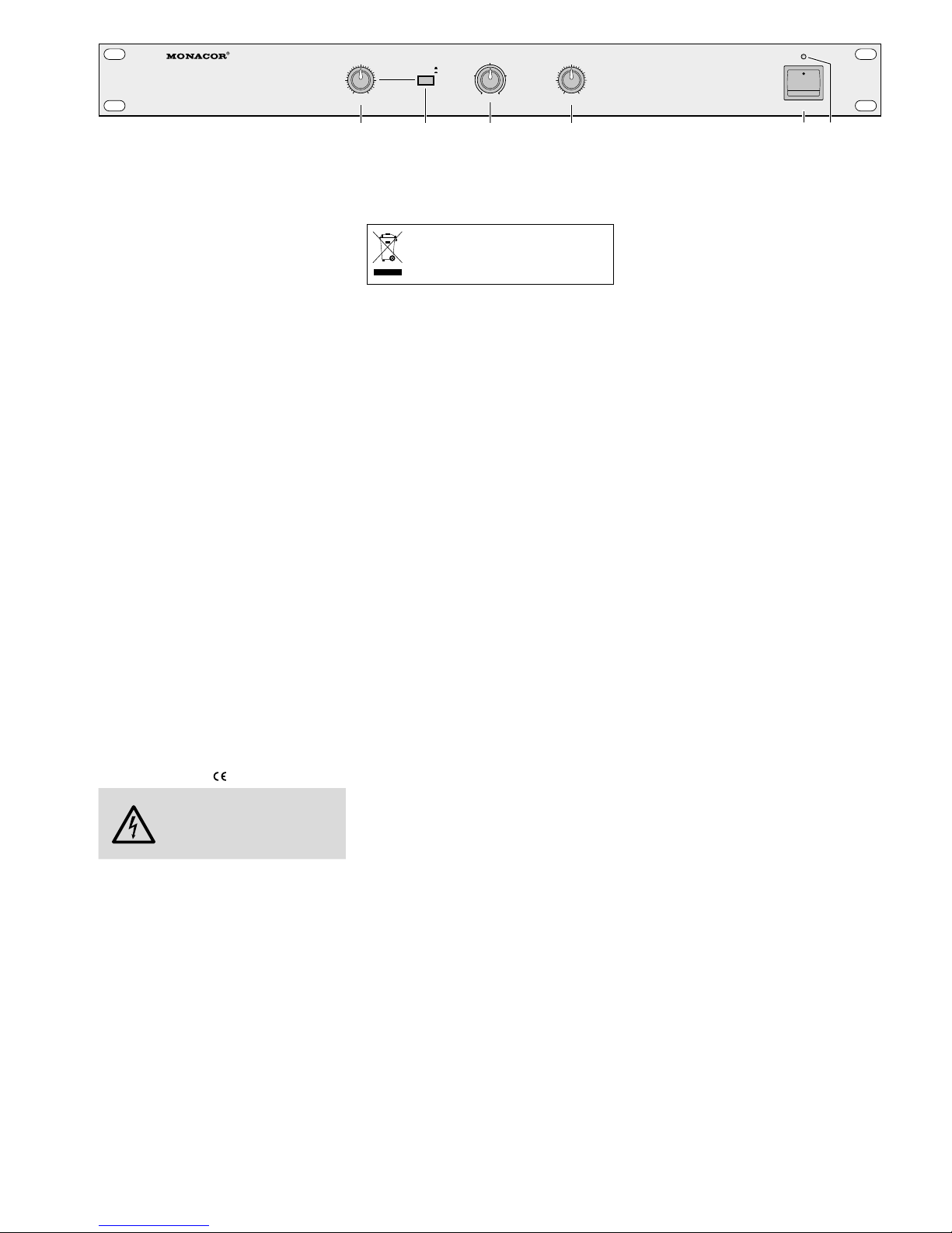
1 2 3 4 5 6
Frequenzweiche fürSubwoofer
Diese Anleitung richtet sich an Benutzer mit Grundkenntnissen in der Audiotechnik. Bitte lesen Sie die
Anleitung vor dem Betrieb gründlich durch und
heben Sie sie für ein späteres Nachlesen auf.
1 Übersicht
1 Pegelregler für die Subwoofer-Kanäle
2
Umschalter für die Phasenlage der Sub wooferKanäle
Taste gedrückt: Phasenlage um 180° gedreht
nicht gedrückt: Phasenlage normal
3 Regler für die Trennfrequenz
4
Pegelregler für die Satellitenlautsprecher- Kanäle
5 Ein- /Ausschalter POWER
6 Betriebsanzeige
7
Netzkabel zum Anschluss an eine Steckdose
(230 V/ 50 Hz)
8 Groundlift-Schalter
GND: die Signalmasse und das Gerätegehäuse
sind elektrisch verbunden
LIFT: die Signalmasse und das Gehäuse sind
getrennt
9 Klemmschraube für einen eventuellen Masse-
anschluss (bei Brummproblemen)
10 Ausgang zum Anschluss eines Verstärkers für
einen einzelnen Mono-Subwoofer
(der Bass des linken und rechten Kanals wird
über einen Subwoofer abgestrahlt)
11
Ausgänge linker und rechter Kanal zum Anschluss eines Verstärkers für die Satellitenlautsprecher
12
Ausgänge linker und rechter Kanal zum Anschluss eines Verstärkers für zwei Subwoofer
(getrennte Basswiedergabe des linken und
rechten Kanals)
13
Eingänge linker und rechter Kanal zum Anschluss der Signalquelle (z. B. Vorverstärker,
Mischpult)
2 Hinweise für den
sicherenGebrauch
Das Gerät entspricht allen relevanten Richtlinien der
EU und ist deshalb mit gekennzeichnet.
WARNUNG
Das Gerät wird mit lebensgefährlicher Netzspannung versorgt.
Nehmen Sie deshalb niemals selbst
Eingriffe daran vor. Es besteht die
Gefahr eines elektrischen Schlages.
•
Verwenden Sie das Gerät nur im Innenbereich.
Schützen Sie es vor Tropf- und Spritzwasser,
hoher Luftfeuchtigkeit und Hitze (zulässiger
Einsatztemperaturbereich 0 – 40 °C).
•
Stellen Sie keine mit Flüssigkeit gefüllten Gefäße,
z. B. Trinkgläser, auf das Gerät.
•
Ziehen Sie sofort den Netzstecker aus der Steckdose, wenn:
1.
sichtbare Schäden am Gerät oder am Netzkabel vorhanden sind,
2.
nach einem Sturz oder Ähnlichem der Verdacht auf einen Defekt besteht,
3. Funktionsstörungen auftreten.
Lassen Sie das Gerät in jedem Fall in einer Fachwerkstatt reparieren.
•
Ein beschädigtes Netzkabel darf nur durch eine
Fachwerkstatt ersetzt werden.
•
Ziehen Sie den Netzstecker nie am Kabel aus
der Steckdose, fassen Sie immer am Stecker an.
•
Für die Reinigung nur ein trockenes, weiches
Tuch verwenden, auf keinen Fall Chemikalien
oder Wasser.
•
Wird das Gerät zweckentfremdet, falsch angeschlossen bzw. bedient oder nicht fachgerecht
repariert, kann keine Haftung für daraus resultierende Sach- oder Personenschäden und keine
Garantie für das Gerät übernommen werden.
Soll das Gerät endgültig aus dem Betrieb
genommen werden, übergeben Sie es
zur umweltgerechten Entsorgung einem
örtlichen Recyclingbetrieb.
3 Einsatzmöglichkeiten
Die Frequenzweiche MCX-200 / SW ermöglicht die
Aufteilung des Frequenzbereiches bei Subwoofer /
Satellitenlautsprecher-Audiosystemen und lässt
sich sowohl für professionelle Zwecke (z. B. Bühne,
Disco) als auch im Heimbereich einsetzen.
Das Gerät ist für die Montage in ein Rack
(482 mm / 19”) vorgesehen, kann aber auch als
frei stehendes Tischgerät verwendet werden. Für
den Einbau in ein Rack wird 1 HE benötigt (HE =
Höheneinheit = 44,45mm).
4 Inbetriebnahme
4.1 Frequenzweiche anschließen
Vor dem Anschließen von Geräten bzw. Ändern
bestehender Anschlüsse die MCX-200 / SW und die
gesamte Audioanlage ausschalten. Alle Ein- und
Ausgänge sind als asymmetrische 6,3-mm-Klinkenbuchsen ausgelegt.
1) Den Ausgang der Signalquelle (z. B. Vorverstär-
ker, Mischpult) an den Eingang INPUT (13) anschließen.
2) Den Eingang des Verstärkers für die Satelliten-
lautsprecher mit den Ausgängen OUTPUT RIGHT /
LEFT SATELLITE (11) verbinden.
3)
Den Eingang des Verstärkers für den / die Subwoofer
a
an den Ausgang MONO OUTPUT (10) anschließen, wenn ein einzelner Mono-Subwoofer aufgestellt wird (der Bass des linken
und rechten Kanals wird über einen Subwoofer abgestrahlt) oder
b
an die Ausgänge OUTPUT RIGHT / LEFT SUBWOOFER (12) anschließen, wenn zwei Subwoofer verwendet werden (zur getrennten
Basswiedergabe des linken und des rechten
Kanals).
4)
Zuletzt den Netzstecker des Netzkabels (7) in eine
Steckdose stecken (230 V/ 50 Hz).
4.2 Einstellungen vornehmen
1)
Vor dem ersten Einschalten der Frequenzweiche die Regler SUBWOOFER OUTPUT (1) und
SATELLITE OUTPUT (4) in die Mittelstellung
drehen (rasten ein) und die Trennfrequenz einstellen.
2) Die Trennfrequenz entsprechend der verwen-
deten Lautsprecher mit dem Regler CROSS OVER
FREQUENCY (3) einstellen (siehe technische
Daten der Lautsprecher). In den meisten Fällen
werden Regal- und kleine Standlautsprecher
optimal durch einen Subwoofer ergänzt, wenn
die eingestellte Trennfrequenz zwischen 60 und
100 Hz liegt. Je niedriger die Trennfrequenz liegt,
desto schwerer lässt sich der Sub woofer akustisch orten; je höher die Trennfrequenz eingestellt
wird, desto stärker ist die Bassunterstützung.
3) Die MCX-200 / SW mit dem Schalter POWER (5)
einschalten – die Betriebsanzeige (6) leuchtet.
4)
Die gesamte Audioanlage einschalten. Zuletzt
immer die Endverstärker einschalten, um Schaltgeräusche zu vermeiden.
5) Um die Ausgangspegel einzustellen, zunächst
mit den beiden Reglern SUBWOOFER OUTPUT (1)
und SATELLITE OUTPUT (4) die angeschlossenen
Endverstärker optimal aussteuern. Da die meisten Endverstärker mit einem Eingangspegelregler
ausgestattet sind, die Einstellung wechselweise
zwischen der Frequenzweiche und den Endverstärkern ausführen.
Anschließend eine natürliche oder eine bewusst verstärke Basswiedergabe einstellen. Wird
der Bassbereich zu schwach wiedergegeben, den
Regler SATELLITE OUTPUT entsprechend zurückdrehen. Ist die Basswiedergabe überbetont, den
Regler SUBWOOFER OUTPUT entsprechend zurückdrehen. (Nachdem die Endverstärker opti
mal ausgesteuert wurden, nie einen der Regler
OUTPUT weiter aufdrehen, da sonst der entsprechende Endverstärker übersteuert wird.)
6) Bei der Aufstellung der Lautsprecher kann es zu
einer unterschiedlichen Phasenlage zwischen
den Schallwellen der (des) Subwoofer(s) und den
Schallwellen der Satellitenlautsprechern kommen. Um dieses auszugleichen, den Schalter
SUBWOOFER PHASE (2) wechselweise schalten,
und die lauteste Basswiedergabe am endgültigen
Hörplatz ermitteln. Anschließend eventuell mit
dem Regler SUBWOOFER OUTPUT (1) die Basswiedergabe entsprechend verringern.
4.3 Groundlift-Schalter
Ist bei der Installation der Audiogeräte eine Masseschleife entstanden (z. B. vom Gehäuse der
Frequenzweiche über ein Rack zu einem anderen
Gerätegehäuse), tritt ein Brummen auf (besonders
hörbar bei leisen Musikpassagen). Diese Masseschleife lässt sich mit dem Schalter GROUNDLIFT(8)
auf der Geräterückseite unterbrechen. Dazu den
Schalter in die Position LIFT schieben. Das Brummen
sollte aufhören.
Andererseits ist der Verstärker nicht gegen elektrische Störfelder abgeschirmt, wenn das Gehäuse
nicht an Masse liegt. In diesem Fall den Schalter
in die Position GND schieben. Im Zweifelsfall den
Schalter wechselweise schalten, um die optimale
Einstellung zu finden.
5 Technische Daten
Frequenzbereich: � � � � � � � � �10 – 30 000 Hz, −0,5 dB
Trennfrequenz: � � � � � � � � � �60 – 500 Hz
Flankensteilheit: � � � � � � � � �12 dB / Oktave
Hochpassfilter: � � � � � � � � � � �15 Hz, 12 dB / Oktave
Klirrfaktor: � � � � � � � � � � � � � � < 0,03 %
Eingang: � � � � � � � � � � � � � � �6,3-mm-Klinke, asym�
max� Eingangspegel: � � � � � 6 V (16 dBV)
Impedanz: � � � � � � � � � � � �56 kΩ
Ausgänge: � � � � � � � � � � � � � � 6,3-mm-Klinke, asym�
Ausgangspegel: � � � � � � � � ±10 dB vom Eingangspegel
einstellbar, max� 6 V
Impedanz: � � � � � � � � � � � �100 Ω
Störabstand: � � � � � � � � � � � �> 80 dB
Stromversorgung: � � � � � � � �230 V/ 50 Hz / 5 VA
Abmessungen (B × H × T): � � 482 × 44,5 × 185 mm, 1 HE
Gewicht: � � � � � � � � � � � � � � �2 kg
Änderungen vorbehalten.
Diese Bedienungsanleitung ist urheberrechtlich für
MONACOR ® INTERNATIONAL GmbH & Co. KG geschützt.
Eine Reproduktion für eigene kommerzielle Zwecke – auch
auszugsweise – ist untersagt.
Page 5

5
English
230V~
50Hz
SUBWOOFERSATELLITE
RIGHT LEFT
SUBWOOFERSATELLITE
OUTPUT LEFTOUTPUT RIGHT INPUT
MONO OUTPUT
SUBWOOFER
LIFTGND
GND
7 8 9 10 11 12 13
Crossover Network forSubwoofer
These operating instructions are intended for users
with basic knowledge in audio technology. Please
read the instructions carefully prior to operating the
unit and keep them for later reference.
1 Overview
1 Level control for the subwoofer channels
2 Push-button switch for the phase of the sub-
woofer channels
push -button p ressed: phase turned by 180°
push-button not pressed: normal phase
3 Control for the crossover frequency
4 Level control for the channels of the satellite
speakers
5 POWER switch
6 Power LED
7 Mains cable for connection to a mains socket
(230 V/ 50 Hz)
8 Groundlift switch
GND: the signal ground and the housing of
the unit are electrically connected
LIFT: the signal ground and the housing are
separated
9
Terminal screw for a ground connection, if
re quired (in case of hum noise problems)
10
Output to connect an amplifier for a single
mono subwoofer (the bass range of the left and
right channels is radiated via one subwoofer)
11 Outputs of the left and right channels to con-
nect an amplifier for the satellite speakers
12 Outputs of the left and right channels to con-
nect an amplifier for two subwoofers (sepa-
rate bass reproduction of the left and right
channels)
13 I
nputs of the left and right channels
to connect
the signal source (e. g. preamplifier, mixer)
2 Safety Notes
The unit corresponds to all relevant directives of the
EU and is therefore marked with .
WARNING
The unit uses dangerous mains voltage. Leave servicing to skilled personnel only. Inexpert handling or
modification of the unit may result
in electric shock.
•
The unit is suitable for indoor use only. Protect
it against dripping water and splash water, high
humidity, and heat (ambient temperature range
0 – 40 °C).
•
Do not place any vessels filled with liquid, e. g.
drinking glasses, on the unit.
•
Immediately disconnect the unit from the mains
socket
1. if there is visible damage to the unit or to the
mains cable,
2. if a defect might have occurred after the unit
was dropped or suffered a similar accident,
3. if malfunctions occur.
In any case the unit must be repaired by skilled
personnel.
•
A damaged mains cable must be replaced by
skilled personnel only.
•
Never pull the mains cable to disconnect the
mains plug from the mains socket, always seize
the plug.
•
Use a dry dust cloth only for cleaning; never use
chemicals or water.
•
No guarantee claims for the unit and no liability
for any resulting personal damage or material
dam age will be accepted if the unit is used for
other pur poses than originally intended, if it is
not correctly con nected or operated, or if it is
not repaired in an expert way.
•
Important for U. K. Customers!
The wires in this mains lead are coloured in
ac cordance with the following code:
blue = neutral
brown = live
As the colours of the wires in the mains lead
of this appliance may not correspond with the
coloured markings identifying the terminals in
your plug, proceed as follows:
1. The wire which is coloured blue must be connected to the terminal which is marked with
the letter N or coloured black.
2.
The wire which is coloured brown must be
con nected to the terminal which is marked
with the letter L or coloured red.
If the unit is to be put out of operation
definitively, take it to a local recycling
plant for disposal which is not harmful
to the environment.
3 Applications
The crossover network MCX-200 / SW allows to
split the frequency range for subwoofer / satellite
audio systems and can be used both for professional applications (e. g. stage, disco) and for home
applications.
The unit is designed for installation into a rack
(482 mm / 19”) but can also be used as a table top
unit. For rack installation, 1 rack space (44.45 mm)
is required.
4 Setting into Operation
4.1 Connecting the crossover network
Prior to connecting the units or to changing existing
connections, switch off the MCX-200 / SW and the
entire audio system. All inputs and outputs are designed as unbalanced 6.3 mm jacks.
1)
Connect the output of the signal source (e. g.
preamplifier, mixer) to the INPUT (13).
2) Connect the input of the amplifier for the sat-
ellite speakers to the outputs OUTPUT RIGHT/
LEFT SATELLITE (11).
3) Connect the input of the amplifier for the sub-
woofer(s)
a to the MONO OUTPUT (10) if a single mono
subwoofer is set up (the bass range of the left
and right channels is radiated via one subwoofer) or
b
to the outputs OUTPUT RIGHT/ LEFT SUBWOOFER (12) if two subwoofers are used
(for separate bass reproduction of the left
and right channels).
4) Finally connect the plug of the mains cable (7)
to a mains socket (230 V/ 50 Hz).
4.2 Making adjustments
1) Prior to switching on the crossover network for
the first time, turn the controls SUBWOOFER
OUTPUT (1) and SATELLITE OUTPUT (4) to midposition (they engage) and adjust the crossover
frequency.
2) Adjust the crossover frequency with the con-
trol CROSSOVER FREQUENCY (3) according
to the speakers used (see specifications of the
speak ers). In most cases, shelf speakers and
small standing speakers are supplemented by a
subwoofer in an optimum way if the crossover
frequency is adjusted between 60 and 100 Hz.
The lower the crossover frequency, the more difficult the acoustic localization of the subwoofer.
The higher the crossover frequency, the more
powerful the bass support.
3)
Switch on the MCX-200 / SW with the POWER
switch (5) – the power LED (6) lights up.
4)
Switch on the entire audio system. To prevent
switching noise, always switch on the power
amplifiers last of all.
5)
To adjust the output levels, first use the two
controls SUBWOOFER OUTPUT (1) and SATELLITE OUTPUT (4) to adjust the connected power
amplifiers to an optimum level. As most power
amplifiers are pro vided with an input level control, make the adjustment alternately between
the crossover network and the power amplifiers.
Then adjust a natural or a deliberately amplified bass reproduction. If the reproduction of
the bass range is too poor, turn back the control SATELLITE OUTPUT accordingly. If the bass
reproduction is overemphasized, turn back the
control SUBWOOFER OUTPUT accordingly. (After
the power amplifiers have been adjusted to an
optimum level, never advance one of the controls
OUTPUT any further; otherwise, the corresponding amplifier will be overloaded.)
6)
When setting up the speakers, a different phase
between the sound waves of the subwoofer(s)
and of the satellite speakers can occur. To compensate this, press the push-button SUB WOOFER
PHASE (2) alternately and determine the highest bass reproduction at the final place of hearing. If necessary, reduce the bass reproduction
accordingly by means of the control SUBWOOFER
OUTPUT (1).
4.3 Groundlift switch
If there is a ground loop after the audio units have
been installed (e. g. from the housing of the crossover network via a rack to another housing of a
unit), a hum noise occurs (to be heard especially
during music passages of low volume). This ground
loop can be interrupted with the GROUNDLIFT
switch (8) at the rear panel of the unit. For this
purpose, slide the switch to the position LIFT. The
hum noise should stop then.
On the other hand, the amplifier is not shielded
against electric noise fields if the housing is not connected to ground. In this case, slide the switch to
the position GND. In case of doubt, set the switch
alternately to find the optimum adjustment.
5 Specifications
Frequency range: � � � � � � � � �10 – 30 000 Hz, −0�5 dB
Crossover frequency: � � � � � �60 – 500 Hz
Slope: � � � � � � � � � � � � � � � � �12 dB / octave
High-pass filter: � � � � � � � � � �15 Hz, 12 dB / octave
THD: � � � � � � � � � � � � � � � � � �< 0�03 %
Input: � � � � � � � � � � � � � � � � � 6�3 mm jacks, unbal�
max� input level: � � � � � � � �6 V (16 dBV)
impedance:� � � � � � � � � � � �56 kΩ
Outputs: � � � � � � � � � � � � � � �6�3 mm jacks, unbal�
output level: � � � � � � � � � � �±10 dB adjustable from
input level, max� 6 V
impedance:� � � � � � � � � � � �100 Ω
S / N ratio: � � � � � � � � � � � � � � > 80 dB
Power supply: � � � � � � � � � � �230 V/ 50 Hz / 5 VA
Dimensions (W × H × D): � � �482 × 44�5 × 185 mm, 1 RS
Weight: � � � � � � � � � � � � � � � � 2 kg
Subject to technical modification.
All rights reserved by MONACOR ® INTERNATIONAL GmbH
& Co. KG. No part of this instruction manual may be reproduced in any form or by any means for any commercial use.
Page 6

6
Français
MCX-2 00/SW
POWER
NORMAL
REVERSE
60
220
100 350
Hz 500
SUBWOOFER
PHASE
CROSSOVER FREQUENCYSUBWOOFER
OUTPUT
-
10 dB +10
LEVEL
SATELLITE
OUTPUT
-
10 dB +10
LEVEL
1 2 3 4 5 6
Filtre de fréquences
poursubwoofer
Cette notice s’adresse aux utilisateurs avec des
connaissances techniques de base en audio. Veuillez lire la présente notice avec attention avant le
fonctionnement et conservez-la pour pouvoir vous
y reporter ultérieurement.
1 Eléments et branchements
1 Réglage de niveau pour les canaux subwoofer
2 Commutateur de phase pour les canaux sub-
woofer
touche enfoncée : phase tournée de 180°
touche non enfoncée : phase normale
3 Réglage de la fréquence de coupure
4 Réglage des canaux haut-parleurs satellites
5 Interrupteur POWER Marche /Arrêt
6 Témoin de fonctionnement
7 Cordon secteur pour un branchement au sec-
teur 230 V/ 50 Hz
8 Interrupteur Groundlift
GND: la masse du signal et le boîtier sont élec-
triquement reliés
LIFT: la masse du signal et le boîtier sont sé-
parés
9 Borne à vis pour un branchement éventuel à
la masse (en cas de ronflements)
10
Sortie permettant de brancher un amplificateur
pour un seul subwoofer mono (la partie grave
des canaux gauche et droit est rayonnée via
un subwoofer)
11 Sorties des canaux droit et gauche pour bran-
cher un amplificateur pour les haut-parleurs
satellites
12 Sorties des canaux droit et gauche pour bran-
cher un amplificateur pour deux subwoofers
(restitution séparée des graves des canaux
droit et gauche)
13 Entrées des canaux droit et gauche pour bran-
cher la source du signal (par exemple une table
de mixage, un préamplificateur)
2 Conseils d’utilisation et
desécurité
L’appareil répond à toutes les directives nécessaires
de l’Union Européenne et porte donc le symbole .
AVERTISSEMENT
Cet appareil est alimenté par
une tension dangereuse. Ne touchez jamais l’intérieur de l’appareil car, en cas de mauvaise
manipulation, vous pourriez
subir une décharge électrique.
•
L’appareil n’est conçu que pour une utilisation en
intérieur. Protégez-le des éclaboussures, de tout
type de projections d‘eau, d’une humidité d‘air
élevée et de la chaleur (la plage de température
ambiante admissible est de 0 – 40 °C).
•
En aucun cas, vous ne devez poser d’objets
contenant du liquide ou par exemple, un verre,
sur l’appareil.
•
Débranchez le cordon secteur immédiatement
dans les cas suivants :
1. l’appareil ou le cordon secteur présente des
dommages visibles,
2.
après une chute ou un accident similaire, vous
avez un doute sur l’état de l’appareil.
3. des dysfonctionnements apparaissent.
Dans tous les cas, les dommages doivent être
réparés par un technicien spécialisé.
•
Tout cordon secteur endommagé doit être remplacé impérativement par un technicien spécialisé.
•
Ne débranchez jamais l’appareil en tirant sur le
cordon secteur ; retirez toujours le cordon secteur en tirant la fiche.
•
Pour nettoyer l‘appareil, utilisez un chiffon sec,
en aucun cas de produits chimiques ou d‘eau.
•
Nous déclinons toute responsabilité en cas de
dommages matériels ou corporels résultants si
l’appareil est utilisé dans un but autre que celui
pour lequel il a été conçu, s’il n’est pas correctement branché ou utilisé ou s’il n’est pas réparé
par une personne habilitée, en outre, la garantie
deviendrait caduque.
Lorsque l’appareil est définitivement retiré
du service, vous devez le déposer dans une
usine de recyclage à proximité pour contribuer à son élimination non polluante.
CARTONS ET EMBALLAGE
PAPIER À TRIER
3 Possibilités d’utilisation
Le filtre de fréquences MCX-200 / SW permet de
répartir la plage de fréquences pour des systèmes
audio subwoofer / haut-parleurs satellites et peut
également être utilisé à des fins professionnelles
(scène, discothèque) et domestiques.
Il est prévu pour un montage en rack (482 mm /
19”) et peut également être directement posé
sur une table ; pour un montage en rack, 1 unité
(1 U = 44,45 mm) est nécessaire.
4 Fonctionnement
4.1 Branchements du filtre
Avant d’effectuer les branchements ou de les modifier, veillez à ce que le système audio et le filtre
soient débranchés. Toutes les entrées et sorties sont
configurées en prises jack 6,35 asymétriques.
1)
Reliez la sortie de la source (p. ex. préamplificateur, table de mixage) à l’entrée INPUT (13).
2) Reliez l’entrée de l’amplificateur pour les haut-
parleurs satellites aux sorties OUTPUT RIGHT/ LEFT
SATELLITE (11).
3)
Reliez l’entrée de l’amplificateur pour le / les
subwoofer(s)
a à la sortie MONO OUTPUT (10) lorsqu’un seul
subwoofer mono est installé (la partie grave
des canaux droit et gauche est rayonnée via
un subwoofer) ou
b
aux sorties OUTPUT RIGHT/ LEFT SUB WOOFER
(12) lorsque deux subwoofers sont utilisés
(pour une restitution séparée des graves des
canaux droit et gauche).
4) Reliez ensuite le cordon secteur (7) à une prise
230 V/ 50 Hz.
4.2 Réglages
1)
Avant la première mise sous tension, mettez les réglages SUBWOOFER OUTPUT (1) et
SATELLITE OUTPUT (4) sur la position médiane (ils
s’enclenchent), réglez la fréquence de coupure.
2)
Réglez la fréquence de coupure, avec le réglage CROSSOVER FREQUENCY (3), selon le
type de haut-parleurs utilisés (reportez-vous aux
caractéristiques techniques des haut-parleurs).
Dans la majorité des cas, les haut-parleurs sur
pied ou pour étagères sont complétés par un
subwoofer de manière optimale si la fréquence de
coupure est réglée entre 60 et 100 Hz. Plus la fréquence est basse, plus la localisation acoustique
du subwoofer est difficile. Plus la fréquence est
élevée, plus le support des graves est puissant.
3)
Allumez le MCX-200 / SW avec l’interrupteur
POWER (5); le témoin de fonctionnement (6)
situé au-dessus brille.
4) Allumez l’ensemble du système audio, l’amplificateur en dernier pour éviter tout bruit fort à
l’allumage.
5) Pour régler les niveaux de sortie, utilisez tout
d’abord les deux réglages SUBWOOFER OUTPUT(1) et SATELLITE OUPUT (4) pour ré gler de
manière optimale les amplificateurs reliés. La majorité des amplificateurs est dotée d’un réglage
de niveau d’entrée, faites alternativement les
réglages entre le filtre et les amplificateurs.
Réglez ensuite une restitution des graves
naturelle ou forte ; si la reproduction des graves
est trop pauvre, tournez le réglage SATELLITE
OUTPUT vers la gauche en conséquence ; si la
restitution des graves est trop riche, tournez le
réglage SUB WOOFER OUTPUT vers la gauche
(une fois les amplificateurs réglés de manière
optimale, n’augmentez jamais un des réglages
OUTPUT, vous engendreriez une surcharge sur
l’amplificateur).
6) Lors du montage des haut-parleurs, une phase
différente entre les ondes sonores du (des)
subwoofer(s) et les haut-parleurs satellites peut
apparaître. Pour compenser cela, enfoncez puis
relâchez l’interrupteur SUBWOOFER PHASE (2)
et déterminez la reproduction des graves la plus
grande, à l’endroit du lieu d’écoute. Si nécessaire, réduisez la part des graves avec le potentiomètre SUBWOOFER OUTPUT (1).
4.3 Interrupteur Groundlift
Si lors de l’installation d’appareils audio, un bou clage de masse apparaît, (p. ex. du boîtier du filtre,
via un rack, vers le boîtier d’un autre appareil), des
ronflements apparaissent (particulièrement audibles
pour des morceaux de volume bas). Vous pouvez
interrompre le bouclage de masse avec l’interrupteur GROUNDLIFT (8) situé sur la face arrière et le
mettre sur LIFT. Le ronflement doit cesser.
En outre, l’amplificateur n’est pas blindé contre
les champs perturbateurs électriques si le boîtier
n’est pas relié à la masse. Dans ce cas, mettez le
sélecteur sur la position GND. En cas de doute,
commutez alternativement le sélecteur de manière
à obtenir le réglage optimal.
5 Caractéristiques techniques
Bande passante : � � � � � � � � � 10 – 30 000 Hz, −0,5 dB
Fréquence de coupure : � � � �60 – 500 Hz
Pente : � � � � � � � � � � � � � � � �12 dB / octave
Filtre passe-haut : � � � � � � � �15 Hz, 12 dB / octave
Taux de distorsion : � � � � � � � < 0,03 %
Entrée : � � � � � � � � � � � � � � � �prises jack 6,35, asym�
Niveau d’entrée max : � � � � 6 V (16 dBV)
Impédance : � � � � � � � � � � �56 kΩ
Sorties : � � � � � � � � � � � � � � � �prises jack 6,35, asym�
Niveau de sortie : � � � � � � �±10 dB réglage à partir du
niveau d’entrée, 6V max�
Impédance : � � � � � � � � � � �100 Ω, asymétrique
Rapport signal / bruit :� � � � � �> 80 dB
Alimentation : � � � � � � � � � � �230 V/ 50 Hz / 5 VA
Dimensions (L × H × P) : � � �482 × 44,5 × 185 mm, 1 U
Poids : � � � � � � � � � � � � � � � � �2 kg
Tout droit de modification réservé.
Notice d’utilisation protégée par le copyright de
MONACOR ® INTERNATIONAL GmbH & Co. KG. Toute
reproduction même partielle à des fins commerciales est
interdite.
Page 7

7
Italiano
230V~
50Hz
SUBWOOFERSATELLITE
RIGHT LEFT
SUBWOOFERSATELLITE
OUTPUT LEFTOUTPUT RIGHT INPUT
MONO OUTPUT
SUBWOOFER
LIFTGND
GND
7 8 9 10 11 12 13
Filtro di frequenza per subwoofer
Queste istruzioni sono rivolte a utenti con conoscenze base nella tecnica audio. Vi preghiamo di
leggerle attentamente prima dell’installazione e di
conservarle per un uso futuro.
1 Panoramica
1 Regolatore livello per i canali subwoofer
2 Commutatore per le fasi dei canali subwoofer
tasto premuto: fase invertita di 180°
non premuto: fase normale
3 Regolatore per frequenza di taglio
4 Regolatore livello per i canali degli altoparlanti
satelliti
5 Interruttore on / off POWER
6 Spia di funzionamento
7 Cavo rete per 230 V/ 50 Hz
8 Interruttore Groundlift
GND: la massa del segnale e il contenitore dello
strumento sono collegati elettricamente
LIFT: la massa del segnale e il contenitore sono
separati
9
Vite per un eventuale collegamento della massa
(nel caso di ronzii)
10 Uscita per il collegamento di un amplificatore
per un subwoofer mono singolo (i bassi dei
canali di destra e di sinistra vengono riprodotti
da un solo subwoofer)
11
Uscite dei canali di destra e di sinistra per il
collegamento di un amplificatore per gli altoparlanti satelliti
12
Uscite dei canali di destra e di sinistra per il
collegamento di un amplificatore per due subwoofer (riproduzione separata dei bassi per i
canali di destra e di sinistra)
13 Ingressi dei canali di destra e di sinistra per il
collegamento della sorgente (p. es. preamplificatore, mixer)
2 Avvertenze di sicurezza
Quest’apparecchio è conforme a tutte le direttive
rilevanti dell’UE e pertanto porta la sigla
.
AVVERTIMENTO
L’apparecchio funziona con
pericolosa tensione di rete. Non
intervenire mai personalmente al
suo interno. La manipolazione
scorretta può provocare delle
scariche elettriche pericolose.
•
Far funzionare l’apparecchio solo all’interno
di locali. Proteggerlo dall’acqua gocciolante e
dagli spruzzi d’acqua, da alta umidità dell’aria
e dal calore (temperatura d’impiego ammessa
fra 0 – 40 °C).
•
Non posare mai dei contenitori con liquidi (p. es.
bicchieri) sull’apparecchio.
•
Staccare subito la spina dalla presa di rete se:
1.
l’apparecchio o il cavo rete presentano dei
danni visibili;
2. dopo una caduta o dopo eventi simili sussiste
il sospetto di un difetto;
3. l’apparecchio non funziona correttamente.
Per la riparazione rivolgersi sempre ad una officina competente.
•
Il cavo rete, se danneggiato, deve essere sostituito solo da un laboratorio specializzato
•
Staccare il cavo rete afferrando la spina, senza
ti rare il cavo.
•
Per la pulizia usare solo un panno morbido,
asciutto; non impiegare in nessun caso prodotti
chimici o acqua.
•
Nel caso di uso improprio, di collegamento sba-
gliato, di impiego scorretto o di riparazione non a
regola d’arte non si assume nessuna responsabilità per eventuali danni consequenziali a persone
o a cose e non si assume nessuna garanzia per
l’apparecchio.
Se si desidera eliminare l’apparecchio
definitivamente, consegnarlo per lo
smaltimento ad un’istituzione locale per
il riciclaggio.
3 Possibilità d’impiego
Il filtro di frequenza MCX-200 / SW permette la
separazione delle frequenze nei sistemi audio con
subwoofer ed altoparlanti satelliti ed è adatto sia
per usi professionali (palcoscenico, discoteca) che
privati.
Il filtro è previsto per il montaggio in un rack
(482 mm / 19”), ma può essere collocato anche su
un tavolo. Per il montaggio nel rack è richiesta un’unità di altezza (= 44,45 mm).
4 Messa in funzione
4.1 Collegare il filtro
Prima di collegare degli apparecchi o modificare
i collegamenti esistenti occorre spegnere il MCX200 / SW e l’intero impianto audio. Tutti gli ingressi
e tutte le uscite sono con prese jack 6,3 mm asimmetriche.
1)
Collegare l’uscita della sorgente (p. es. preampli
-
ficatore, mixer) con l’ingresso INPUT (13).
2) Collegare l’ingresso dell’amplificatore per gli al-
toparlanti satelliti con le uscite OUTPUT RIGHT /
LEFT SATELLITE (11).
3)
Collegare l’ingresso dell’amplificatore per il / i
sub woofer
a con l’uscita MONO OUTPUT (10) nel caso di
un subwoofer singolo (riproduzione dei bassi
di destra e di sinistra mediante un solo subwoofer), oppure
b
con le uscite OUTPUT RIGHT/ LEFT SUBWOOFER (12) nel caso di due subwoofer
(riproduzione separata dei bassi di destra e
di sinistra).
4) Alla fine inserire la spina del cavo rete (7) in una
presa (230 V/ 50 Hz).
4.2 Eseguire le impostazioni
1)
Prima della prima accensione del filtro portare
i regolatori SUBWOOFER OUTPUT (1) e SATELLITE OUTPUT (4) in posizione centrale (scatto) ed
impostare la frequenza di taglio.
2) Con il regolatore CROSSOVER FREQUENCY (3)
impostare la frequenza di taglio a seconda
degli altoparlanti impiegati (vedi i dati tecnici
degli altoparlanti). Nella maggior parte dei casi,
i piccoli altoparlanti trovano un’integrazione
ideale con il subwoofer se la frequenza di taglio è impostata fra 60 e 100 Hz. Più è bassa la
frequenza di taglio, più è difficile identificare il
subwoofer; aumentando la frequenza di taglio,
si rinforzano i bassi.
3)
Accendere il MCX-200 / SW con l’interruttore
POWER (5) – si accende la spia di funzionamento (6).
4) Accendere il resto dell’impianto. Accendere gli
amplificatori finali per ultimi per evitare i rumori
di commutazione.
5) Per impostare il livello di uscita, regolare prima
in modo ottimale gli amplificatori finali collegati servendosi dei due regolatori SUBWOOFER
OUTPUT (1) e SATELLITE OUTPUT (4). Dato che
la maggior parte degli amplificatore finali sono
equipaggiati con un regolatore del livello d’ingresso, l’impostazione può essere eseguita sul
filtro e sugli amplificatori.
Successivamente occorre impostare una
ri pro duzione naturale o accentuata dei bassi. Se
i bassi sono troppo deboli, abbassare il regolatore SATELLITE OUTPUT. Se i bassi sono troppo
accentuati, abbassare il regolatore SUBWOOFER
OUTPUT (dopo l’impostazione ottimale dell’amplificatore finale mai aprire di più il regolatore
OUTPUT per non sovrapilotare l’amplificatore).
6)
Durante il collocamento degli altoparlanti si
possono differenziare le fasi fra le onde sonore
del / dei subwoofer e quelle degli altoparlanti
satelliti. Per compensare questo fatto azionare il
commutatore SUBWOOFER PHASE (2) e individuare la posizione del commutatore con la più
forte riproduzione dei bassi sul posto di ascolto.
Quindi, se necessario, ridurre i bassi con il regolatore SUBWOOFER OUTPUT (1).
4.3 Interruttore Groundlift
Se durante l’installazione degli apparecchi audio si
è creato un anello di terra (per esempio dal contenitore del filtro attraverso il rack verso il contenitore di un altro apparecchio), si nota un ronzio
(percepibile specialmente duranti i brani musicali
a basso volume). Questo anello di terra può es
sere interrotto con l’interruttore GROUNDLIFT (8)
sul retro del filtro, spostandolo in posizione LIFT. Il
ronzio dov reb be quindi terminare.
D’altra parte, l’amplificatore non è schermato
contro disturbi elettrici se il contenitore non è collegato con la massa. In questo caso conviene spostare
l’interruttore in posizione GND. Nel dubbio provare
le due posizioni per trovare l’impostazione ottimale.
5 Dati tecnici
Frequenza passante: � � � � � � 10 – 30 000 Hz, −0,5 dB
Frequenza di taglio: � � � � � � �60 – 500 Hz
Pendenza: � � � � � � � � � � � � � �12 dB / oct�
Filtro passa alto: � � � � � � � � � 15 Hz, 12 dB / oct�
Fattore di distorsione: � � � � � < 0,03 %
Ingresso: � � � � � � � � � � � � � � �prese jack 6,3 mm, asimm�
Livello max� d’ingresso: � � � 6 V (16 dBV)
Impedenza: � � � � � � � � � � � 56 kΩ
Uscite: � � � � � � � � � � � � � � � � �prese jack 6,3 mm, asimm�
Livello d’uscita: � � � � � � � � �±10 dB impostabile del
livello d’ingresso, max� 6 V
Impedenza: � � � � � � � � � � � 100 Ω
Rapporto S / R: � � � � � � � � � � � > 80 dB
Alimentazione: � � � � � � � � � �230 V/ 50 Hz / 5 VA
Dimensioni (L × H × P): � � � �482 × 44,5 × 185 mm,
1 unità di altezza
Peso:
� � � � � � � � � � � � � � � � � �2 kg
Con riserva di modifiche tecniche.
La MONACOR ® INTERNATIONAL GmbH & Co. KG si riserva
ogni diritto di elaborazione in qualsiasi forma delle presenti
istruzioni per l’uso. La riproduzione – anche parziale – per
propri scopi commerciali è vietata.
Page 8

8
Español
MCX-2 00/SW
POWER
NORMAL
REVERSE
60
220
100 350
Hz 500
SUBWOOFER
PHASE
CROSSOVER FREQUENCYSUBWOOFER
OUTPUT
-
10 dB +10
LEVEL
SATELLITE
OUTPUT
-
10 dB +10
LEVEL
1 2 3 4 5 6
Filtro de frecuencias para subwoofer
Estas instrucciones de funcionamiento van dirigidas
a usuarios con conocimientos básicos en audio. Lea
atentamente estas instrucciones de funcionamiento
antes de utilizar el aparato y guárdelas para usos
posteriores.
1 Vista general
1 Control de nivel para los canales subwoofer
2
Conmutador de fase para los canales subwoofer
botón pulsado: fase girada a 180º
botón no pulsado: fase normal
3 Control de la frecuencia crossover
4 Control de los canales altavoces satélites
5 Interruptor POWER
6 LED POWER
7 Cable de corriente para una conexión a la red
(230 V/ 50 Hz)
8 Interruptor Groundlift
GND: la masa de la señal y la caja están eléc-
tricamente conectadas
LIFT: la masa de la señal y la caja están sepa-
radas
9
Borne con tornillo para una conexión eventual
a la masa (en caso de zumbidos)
10
Salida para conectar un amplificador para
un subwoofer mono individual (la parte
grave del canal izquierdo y derecho está
radiada a través de un subwoofer)
11
Salidas del canal derecho e izquierdo para
co nec tar un amplificador para los altavoces
satélites
12
Salidas del canal derecho e izquierdo para
conectar un amplificador para dos subwoofers
(reproducción separada de graves del canal
derecho e izquierdo)
13
Entradas del canal derecho e izquierdo para
conectar la fuente de la señal (por ejemplo un
mezclador, un preamplificador)
2 Consejos de seguridad
El aparato cumple con todas las directivas relevantes de la UE y por lo tanto está marcado con el
símbolo .
ADVERTENCIA El aparato utiliza un voltaje peli-
groso. Deje el mantenimiento en
manos del personal cualificado. El
manejo inexperto o la modificación del aparato pueden provocar
una descarga.
•
El aparato está adecuado para utilizarse sólo en
interiores. Protéjalo de goteos y salpicaduras,
elevada humedad del aire y calor (temperatura
ambiente admisible: 0 – 40 °C).
•
No coloque ningún recipiente lleno de líquido
encima del aparato, como por ejemplo un vaso.
•
Inmediatamente desconecte el aparato de la
corriente si:
1. El aparato o el cable de corriente están visiblemente dañados.
2. El aparato ha sufrido daños después de una
caída o accidente similar.
3. No funciona correctamente.
Sólo el personal técnico puede reparar el aparato
bajo cualquier circunstancia.
•
Un cable de corriente dañado solo puede repararse por el personal cualificado.
•
No tire nunca del cable de corriente para desconectarlo de la toma, tire siempre del enchufe.
•
Para limpiar el aparato, utilice un trapo seco y
suave, no utilice nunca productos químicos or
agua.
•
No podrá reclamarse garantía o responsabilidad
alguna por cualquier daño personal o material
resultante si el aparato se utiliza para otros fines
diferentes a los originalmente concebidos, si no
se conecta o se utiliza adecuadamente, o si no
se repara por expertos.
Si va a poner el aparato definitivamente
fuera de servicio, llévelo a la planta de
reciclaje más cercana para que su eliminación no sea perjudicial para el
medioambiente.
3 Posibilidades de utilización
El filtro de frecuencias MCX-200 / SW puede repartir
el rango de frecuencias para sistemas audio
subwoofers / altavoces satélites y puede ser utilizado
por fines profesionales (p. ej. escenario, discotecas)
y así como por fines domésticos.
Está concebido para un montaje en rack
(482 mm / 19”) y puede también colocarse en
una mesa. Para un montaje en rack, 1 unidad
(1 U =44,45 mm) es necesaria.
4 Puesta en servicio
4.1 Conexión del filtro
Antes de hacer las conexiones o de modificarlas,
asegúrese de que el MCX-200 / SW y el conjunto
del sistema audio están apagados. Todas las salidas
y entradas están configuradas como tomas jack
6,3 mm asimétricas.
1)
Conecte la salida de la fuente de señal (por
ejemplo preamplificador, mezclador) a la entrada
INPUT (13).
2)
Conecte la entrada del amplificador para los
altavoces satélites a las salidas OUTPUT RIGHT/
LEFT SATELLITE (11).
3) Conecte la entrada del amplificador para el / los
subwoofer / s
a
a la salida MONO OUTPUT (10), cuando un
solo subwoofer mono está instalado (los
graves del canal derecho e izquierdo están
radiadas a través de un subwoofer) o
b
a las salidas OUTPUT RIGHT/ LEFT SUBWOOFER
(12) cuando están utilizados dos subwoofers
(para obtener una reproducción separada de
graves entre el canal derecho e izquierdo).
4)
Conecte luego el cable de corriente (7) a un
enchufe (230 V/ 50 Hz).
4.2 Ajustes
1)
Antes de conectar el aparato, ponga los contoles
SUBWOOFER OUTPUT (1) y SATELLITE OUTPUT
(4) en la posición mediana (encajan) y ajuste la
frecuencia crossover.
2)
Utilice el control CROSSOVER FREQUENCY (3)
para ajustar la frecuencia crossover según el
tipo de los altavoces utilizados (referirse a las
características técnicas de los altavoces). En la
mayoría de los casos, los altavoces para estantería o pequeño altavoces para pies están completados por un subwoofer de manera óptima
si la frecuencia crossover ajustada está entre
60 y 100 Hz. Cuando más baja sea la frecuencia
crossover, más difícil será la localización acústica
del subwoofer. Cuando más grande la frecuencia crossover sea ajustada, más potente será el
soporte de graves.
3) Ponga en marcha el MCX-200 / SW con el interruptor POWER (5); el LED POWER (6) se ilumina.
4) Ponga en marcha el conjunto del sistema audio,
los amplificadores siempre los últimos, para así
evitar todo fuerte ruido al conectar.
5)
Para ajustar los niveles de salida, utilice primero
los dos controles SUBWOOFER OUTPUT (1) y
SATELLITE OUTPUT (4) para ajustar de manera
óptima los amplificadores conectados. La mayoría de los amplificadores están equipados con un
control de nivel de entrada; por lo tanto haga
el ajuste alternativamente entre el filtro y los
amplfificadores.
Ajuste luego una reproducción de los graves
natural o deliberadamente fuerte; si la reproducción de los graves es demasiado pobre, gire el
reglaje SATELLITE OUTPUT en el sentido horario
inverso según corresponda. Si la reproducción
de los graves es demasiado fuerte, gire el control SUBWOOFER OUTPUT en el sentido horario
inversio. (Una vez los amplificadores ajus tados
de manera óptima, nunca aumente más uno
de los controles OUTPUT, esto provocaría una
sobrecarga al amplificador correspondiente.)
6) Durante el montaje de los altavoces, una fase
diferente entre las ondas acústicas del / de los
subwoofer / s y de los altavoces satélites puede
notarse. Para compensar esto, pulse y libere el
interruptor SUBWOOFER PHASE (2) y determine
la reproducción de graves la más alta en el sitio
del lugar de escucha definitivo. Si es necesario, utilice el control SUBWOOFER OUTPUT (1)
para reducir la reproducción de los graves según
corresponda.
Page 9

9
Español
230V~
50Hz
SUBWOOFERSATELLITE
RIGHT LEFT
SUBWOOFERSATELLITE
OUTPUT LEFTOUTPUT RIGHT INPUT
MONO OUTPUT
SUBWOOFER
LIFTGND
GND
7 8 9 10 11 12 13
4.3 Interruptor Groundlift
Si después de la instalacion de los aparatos audio
hay un bucle de masa (por ejemplo desde la caja del
filtro a través de un rack hacia la caja de otro aparato), aparecerán zumbidos (se oyen especialmente
en un trozo de música flojo). Para interrumpir este
bucle de masa, ponga el interruptor GROUNDLIFT
(8) situado en la parte trasera del aparato en la
posición LIFT. El zumbido debería detenerse.
Sin embargo, el amplificador no está blindado
contra los campos eléctricos perturbadores si la caja
no está conectada a la masa. En este caso, ponga
el interruptor en la posición GND. En caso de duda,
coloque el interruptor en manera alternativa para
obtener un ajuste óptimo.
5 Características técnicas
Banda pasante: � � � � � � � � � � 10 – 30 000 Hz, −0,5 dB
Frecuencia crossover: � � � � � � 60 – 500 Hz
Pendiente: � � � � � � � � � � � � � � 12 dB / oct�
Filtro pasa alto: � � � � � � � � � � 15 Hz, 12 dB / oct�
THD: � � � � � � � � � � � � � � � � � �< 0,03 %
Entrada: � � � � � � � � � � � � � � �tomas jack 6,3 mm, asim�
Nivel de entrada: � � � � � � �máx� 6 V (16 dBV)
Impedancia: � � � � � � � � � � �56 kΩ
Salidas: � � � � � � � � � � � � � � � �tomas jack 6,3 mm, asim�
Nivel de salida: � � � � � � � � � ±10 dB ajuste a partir del
nivel de entrada, 6 V máx�
Impedancia: � � � � � � � � � � �100 Ω
Relación señal / ruido: � � � � � � > 80 dB
Alimentación: � � � � � � � � � � � 230 V/ 50 Hz / 5 VA
Dimensiones (B × H × P): � �482 × 44,5 × 185 mm, 1 U
Peso: � � � � � � � � � � � � � � � � � �2 kg
Sujeto a modificaciones técnicas.
Manual de instrucciones protegido por el copyright de
MONACOR ® INTERNATIONAL GmbH & Co. KG. Toda
reproducción mismo parcial para fines comerciales está
prohibida.
Page 10

10
NederlandsDansk
Læs nedenstående sikkerhedsoplys ninger opmærksomt igennem før ibrugtagning af enheden. Bortset fra sikkerhedsoplys nin gerne henvises til den
engel ske, tyske, franske eller italienske tekst.
Vigtige sikkerhedsoplysninger
Denne enhed overholder alle relevante EU-direktiver, og er derfor mærket med
.
ADVARSEL
Enheden benytter livsfarlig netspænding. Udfør aldrig nogen form
for modifikationer på produktet og
indfør aldrig genstande i ventilationshullerne, da du dermed risikere
at få elektrisk stød.
•
Enheden er kun beregnet til indendørs brug.
Be skyt enhederne mod vanddråber og -stænk,
høg luftfugtighed og varme (tilladt temperaturområde i drift 0 – 40 °C).
•
Undgå at placere væskefyldte genstande, som
f. eks. glas, ovenpå enheden.
•
Tag ikke enheden i brug eller tag straks stikket
ud af stikkontakten i følgende tilfælde:
1. hvis der er synlig skade på enheden eller netkablet,
2. hvis der kan være opstået skade, efter at enheden er tabt eller lignende,
3. hvis der forekommer fejlfunktion.
Enheden skal altid repareres af autoriseret personel.
•
Et beskadiget netkabel må kun repareres af producenten eller af autoriseret personel.
•
Tag aldrig stikket ud af stikkontakten ved at
trække i kablet, tag fat i selve stikket.
•
Til rengøring må der kun benyttes en tør, blød
klud; der må under ingen omstændigheder benyttes kemikalier eller vand.
•
Hvis enheden benyttes til andre formål, end den
oprindeligt er beregnet til, hvis den betjenes forkert, eller hvis den ikke repareres af autoriseret
personel, omfattes eventuelle skader ikke af
garantien.
Hvis enheden skal tages ud af drift for
bestandigt, skal den bringes til en lokal
genbrugsstation for bortskaffelse.
Alle rettigheder til denne brugsvejledning tilhører
MONACOR ® INTERNATIONAL GmbH & Co. KG. Ingen
dele af denne vejledning må reproduceres under ingen
omstændigheder til kommerciel anvendelse.
Lees aandachtig de onderstaande veiligheidsvoorschriften, alvorens de apparatuur in gebruik te
ne men. Mocht u bijkomende informatie over de
bediening van de apparatuur nodig hebben, lees
dan de Duitse, Engelse, Franse, of Italiaanse tekst
van deze handleiding.
Veiligheidsvoorschriften
Dit apparaat is in overeenstemming met alle relevante EU-Richtlijnen en is daarom met
geken-
merkt.
WAARSCHUWING De netspanning van het appa-
raat is levensgevaarlijk. Open
het apparaat niet, want door
onzorgvuldige in grepen loopt
u het risico van elektrische
schokken.
•
Het toestel is enkel geschikt voor gebruik binnenskamers. Vermijd druip- en spatwater, uitzonderlijk warme plaatsen en plaatsen met een
hoge vochtigheid (toegestaan omgevingstemperatuurbereik: 0 – 40 °C).
•
Plaats geen bekers met vloeistof zoals drinkglazen op het toestel.
•
Schakel het toestel niet in of trek onmiddellijk de
stekker uit het stopcontact wanneer:
1. het toestel of het netsnoer zichtbaar beschadigd is,
2.
er een defect zou kunnen optreden nadat het
toes tel bijvoorbeeld gevallen is,
3. het toestel slecht functioneert.
Het apparaat moet in elk geval hersteld worden
door een gekwalificeerd vakman.
•
Een beschadigd netsnoer mag alleen in een
werkplaats worden vervangen.
•
Trek de stekker nooit met het snoer uit het stopcontact, maar met de stekker zelf.
•
Verwijder het stof met een droge doek. Gebruik
zeker geen chemicaliën of water.
•
In geval van ongeoorloofd of verkeerd gebruik,
ver keerde aansluiting, foutieve bediening of van
herstelling door een niet-gekwalificeerd persoon
vervalt de garantie en de verantwoordelijkheid
voor hieruit resulterende materiële of lichamelijke schade.
Wanneer het toestel definitief uit bedrijf
genomen wordt, bezorg het dan voor
milieuvriendelijke verwerking aan een
plaatselijk recyclagebedrijf.
Deze gebruiksaanwijzing is door de auteurswet be schermd
eigendom van MONACOR ® INTERNATIONAL GmbH &
Co. KG. Een reproductie – ook gedeeltelijk – voor eigen
commerciële doeleinden is verboden.
Page 11

11
SvenskaSuomi
Ole hyvä ja huomioi aina seuraavat turvallisuutta
koskevat ohjeet ennen laitteen käyttöön ottoa.
Katso käyttöön liittyviä ohjeita Saksan, Englannin,
Ranskan tai Italian kielisistä ohjeista, jos tarvitset
lisää tietoa laitteen käytöstä.
Turvallisuudesta
Tämä laite täyttää kaikki siihen kohdistuvat EU-direktiivit ja sille on myönnetty
hyväksyntä.
VAROITUS
Tämä laite toimii hengenvaarallisella jännitteellä. Älä koskaan tee
mitään muutoksia laitteeseen taikka
asenna mitään ilmanvaihto aukkoihin, koska siitä saattaa seurata sähköisku.
•
Tämä laite soveltuu vain sisätilakäyttöön. Suojele
laitetta kosteudelta, vedeltä ja kuumuudelta (sallittu ympä röivä lämpötila 0 – 40 °C).
•
Älä sijoita laitteen päälle mitään nestettä sisältävää, kuten vesilasia tms.
•
Älä kytke virtaa päälle ja irrota laite välittömästi
sähköverkosta jos:
1. laitteessa on näkyvä vika,
2.
laite on saattanut vaurioitua pudotuksessa tai
vas taavassa tilanteessa,
3. laite toimii väärin.
Kaikissa näissä tapauksissa laitteen saa korjata
vain hyväksytty huolto.
•
Virtajohdon saa vaihtaa vain valtuutettu huoltohenkilö.
•
Älä koskaan irrota verkkoliitintä johdosta vetämällä. Vedä aina itse liittimestä.
•
Puhdista laite pyyhkimällä puhtaalla, kuivalla
kangaspalalla. Älä käytä kemikaaleja tai vettä.
•
Laitteen takuu raukeaa, eikä valmistaja, maahantuoja tai myyjä ota vastuuta mahdollisista välittömis tä tai välillisistä vahingoista, jos laitetta on
käytetty muuhun kuin alkuperäiseen käyttötar-
koitukseen, laitetta on taitamattomasti käytetty
tai kytketty tai jos laitetta on huollettu muussa
kuin valtuutetussa huollossa.
Kun laite poistetaan lopullisesti käytöstä,
vie se paikalliseen kierrätyskeskukseen
jälkikäsittelyä varten.
Kaikki oikeudet pidätetään MONACOR ® INTERNATIONAL
GmbH & Co. KG. Mitään tämän käyttöohjeen osaa ei saa
jäljentää miltään osin käytettäväksi mihinkään kaupallisiin
tarkoituksiin.
Innan enheten tas i bruk, läs först igenom säkerhetsföreskrifterna. Om ytterligare information önskas, läs igenom den tyska, engelska, franska eller
den italienska texten som medföljer.
Säkerhetsföreskrifter
Enheten uppfyller relevanta Eu-direktiv och har
därför försetts med symbolen .
VARNING
Enheten använder högspänning
internt. Gör inga modifieringar i
enheten eller stoppa föremål i ventilhålen. Risk för elskador föreligger.
•
Enheten är endast avsedd för inomhusbruk. En-
heten skall skyddas mot vätskor, hög luftfuktig-
het och hög värme (arbetstemperatur 0 – 40 °C).
•
Placera inte föremål innehållande vätskor, t. ex.
dricksglas, på enheten.
•
Använd inte enheten eller ta ut kontakten ur
eluttaget om något av följande fel uppstår:
1. Enheten eller elsladden har synliga skador.
2. Enheten är skadad av fall e. d.
3. Enheten har andra felfunktioner.
Enheten skall alltid lämnas till verkstad för service.
•
En skadad elsladd skall bytas på verkstad.
•
Drag aldrig ut kontakten genom att dra sladden
utan ta tag i kontaktkroppen.
•
Rengör endast med en ren och torr trasa, använd
aldrig vätskor i någon form då dessa kan rinna
in och orsaka kortslutning.
•
Om enheten används på annat sätt än som avses
eller om den används på felaktigt sätt eller repareras av obehörig personal upphör alla garantier att gälla. Dessutom tas i dessa fall inget
ansvar för skada som uppkommit på person eller
materiel.
Om enheten ska tas ur drift slutgiltigt, ta
den till en lokal återvinningsanläggning
för en avyttring som inte är skadligt för
miljön.
Alla rättigheter är reserverade av MONACOR ® INTERNATIONAL GmbH & Co. KG. Ingen del av denna instruktionsmanual får eftertryckas i någon form eller på något
sätt användas i kommersiellt syfte.
Page 12

MONACOR INTERNATIONAL GmbH & Co. KG • Zum Falsch 36 • 28307 Bremen • Germany
Copyright© by MONACOR INTERNATIONAL. All rights reserved.
A-0374.99.03.02.2017
 Loading...