

Page 1
BEDIENUNGSANLEITUNG • INSTRUCTION MANUAL
MODE D’EMPLOI • ISTRUZIONI PER L’USO • GEBRUIKSAANWIJZING
MANUAL DE INSTRUCCIONES • INSTRUKCJA OBSŁUGI
SIKKERHEDSOPLYSNINGER • SÄKERHETSFÖRESKRIFTER • TURVALLISUUDESTA
LED-DMX-LICHTEFFEKTGERÄT
LED DMX LIGHT EFFECT UNIT
JEU DE LUMIÈRE DMX À LEDS
UNITÀ DMX PER EFFETI DI LUCE CON LED
“STAR BALL”
LED-300DX/RGB Best.-Nr. 38.3710
LED-300DX/WS Best.-Nr. 38.3660
Page 2
2
10
11
12
1234567
89
Page 3
3
wwwwww..iimmggssttaaggeelliinnee..ccoomm
Bevor Sie einschalten …
Wir wünschen Ihnen viel Spaß mit Ihrem neuen
Gerät von „img Stage Line“. Bitte lesen Sie diese
Bedienungsanleitung vor dem Betrieb gründlich
durch. Nur so lernen Sie alle Funktionsmöglichkeiten kennen, vermeiden Fehlbedienungen und
schützen sich und Ihr Gerät vor eventuellen Schäden durch unsachgemäßen Gebrauch. Heben
Sie die Anleitung für ein späteres Nachlesen auf.
Der deutsche Text beginnt auf der Seite 4.
Before switching on …
We wish you much pleasure with your new “img
Stage Line” unit. Please read these operating
instructions carefully prior to operating the unit.
Thus, you will get to know all functions of the unit,
operating errors will be prevented, and yourself
and the unit will be protected against any damage
caused by improper use. Please keep the oper ating instructions for later use.
The English text starts on page 8.
Avant toute installation …
Nous vous souhaitons beaucoup de plaisir à utiliser cet appareil “img Stage Line”. Lisez ce mode
dʼemploi entièrement avant toute utilisation. Uniquement ainsi, vous pourrez apprendre lʼensemble des possibilités de fonctionnement de lʼappareil, éviter toute manipulation erronée et vous
protéger, ainsi que lʼappareil, de dommages
éventuels engendrés par une utilisation inadaptée. Conservez la notice pour pouvoir vous y
reporter ultérieurement.
La version française se trouve page 12.
Prima di accendere …
Vi auguriamo buon divertimento con il vostro
nuovo apparecchio di “img Stage Line”. Leggete
attentamente le istruzioni prima di mettere in funzione lʼapparecchio. Solo così potete conoscere
tutte le funzionalità, evitare comandi sbagliati e
proteggere voi stessi e lʼapparecchio da eventuali danni in seguito ad un uso improprio. Conservate le istruzioni per poterle consultare anche
in futuro.
Il testo italiano inizia a pagina 16.
D
A
CH
GB
Antes de la utilización …
Le deseamos una buena utilización para su nue vo aparato “img Stage Line”. Por favor, lea estas
in s trucciones de uso atentamente antes de ha cer
funcionar el aparato. De esta manera conocerá
todas las funciones de la unidad, se pre vendrán
errores de operación, usted y el apa rato estarán
protegidos en contra de todo daño cau sado por
un uso inadecuado. Por favor, guarde las instrucciones para una futura utilización.
La versión española comienza en la página 24.
Voor u inschakelt …
Wij wensen u veel plezier met uw nieuwe apparaat van “img Stage Line”. Lees deze gebruikershandleiding grondig door, alvorens het apparaat
in gebruik te nemen. Alleen zo leert u alle functies
kennen, vermijdt u foutieve bediening en behoedt
u zichzelf en het apparaat voor eventuele schade
door ondeskundig gebruik. Bewaar de handleiding voor latere raadpleging.
De Nederlandstalige tekst vindt u op pagina 20.
Przed uruchomieniem …
Życzymy zadowolenia z nowego produktu “img
Stage Line”. Dzięki tej instrukcji obsługi będą
państwo w stanie poznać wszystkie funkcje tego
urządzenia. Stosując się do instrukcji unikną
państwo błędów i ewentualnego uszkodzenia
urządzenia na skutek nieprawidłowego użytkowania. Prosimy zachować instrukcję.
Tekst polski zaczyna się na stronie 28.
Før du tænder …
Tillykke med dit nye “img Stage Line” produkt.
Læs sikkerhedsanvisningerne nøje før ibrugtagning, for at beskytte Dem og enheden mod skader, der skyldes forkert brug. Gem manualen til
senere brug.
Sikkerhedsanvisningerne findes på side 32.
Innan du slår på enheten …
Vi önskar dig mycket glädje med din nya “img
Stage Line” produkt. Läs igenom säkerhetsföre skrifterna innan en heten tas i bruk för att undvika
skador till följd av felaktig hantering. Behåll
instruktionerna för framtida bruk.
Säkerhetsföreskrifterna återfinns på sidan 32.
Ennen kytkemistä …
Toivomme Sinulle paljon miellyttäviä hetkiä
uuden “img Stage Line” laitteen kanssa. Ennen
laitteen käyttöä pyydämme Sinua huolellisesti
tutustumaan turvallisuusohjeisiin. Näin vältyt
vahingoilta, joita virheellinen laitteen käyttö saattaa aiheuttaa. Ole hyvä ja säilytä käyttöohjeet
myöhempää tarvetta varten.
Turvallisuusohjeet löytyvät sivulta 33.
F
B
CH
I
E
PL DK
S FIN
NL
B
Page 4
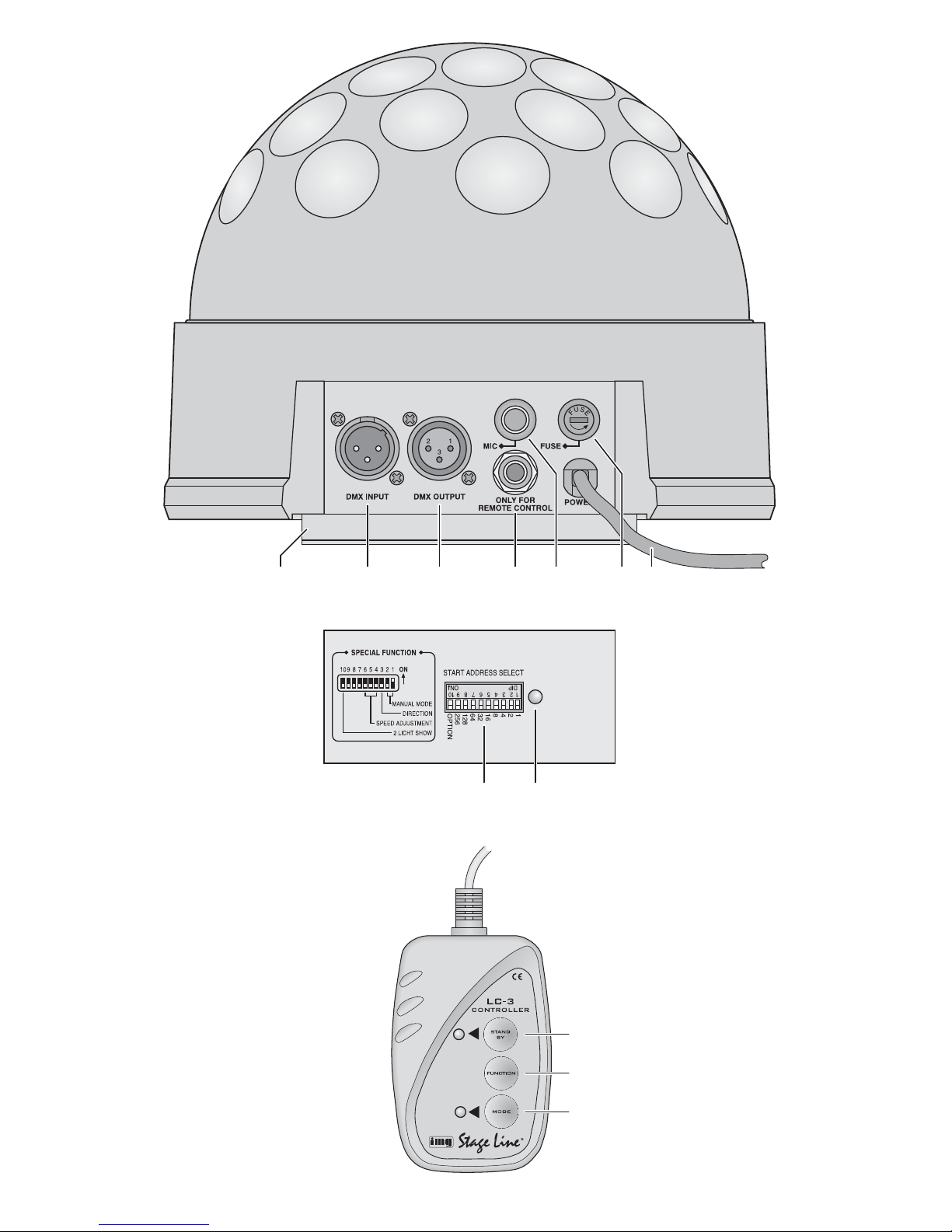
Auf der Seite 2 finden Sie alle be schriebenen Be dienelemente und Anschlüsse.
1 Übersicht der Bedienelemente
und Anschlüsse
1.1 Lichteffektgerät LED-300DX/…
1 Befestigungswinkel
2 DMX-Signal-Eingang (3-pol. XLR) zum Anschluss
eines Lichtsteuergerätes;
Pin 1 = Masse, 2 = DMX
-
, 3 = DMX+
3 DMX-Signal-Ausgang (3-pol. XLR) zum Anschluss
an den DMX-Eingang eines weiteren DMX-Lichteffektgerätes;
Pin 1 = Masse, 2 = DMX
-
, 3 = DMX+
4 Anschlussbuchse für die Fernbedienung LC-3
5 Mikrofon zur Musiksteuerung
6 Halterung für die Netzsicherung
Eine geschmolzene Sicherung nur durch eine gleichen Typs ersetzen.
7 Netzkabel zum Anschluss an eine Steckdose
(230 V~ / 50 Hz)
8 DIP-Schalter Nr. 1 – 9 zum Einstellen der Geräte-
adresse oder der Betriebsart (Master- oder SlaveModus); DIP-Schalter Nr. 10 zur Wahl der Reaktion
im Slave-Modus (
Kapitel 6.2)
9 Kontroll-LED
– leuchtet konstant:
keine DMX- oder Musiksteuerung
– erlischt im Takt der Musik:
Musiksteuerung über das Mikrofon (5)
– blinkt kontinuierlich:
Steuerung über ein DMX-Lichtsteuergerät
1.2 Fernbedienung LC-3
Die Fernbedienung ist als Zubehör erhältlich und
gehört nicht zum Lieferumfang des Lichteffektgerätes.
10 Taste STAND BY zum Ausschalten des Lichtstrahls
11 Taste FUNCTION zur Auswahl verschiedener
Funktionen in Abhängigkeit von dem mit der Taste
MODE (12) gewählten Betriebsmodus
12 Taste MODE zum Umschalten zwischen
Stroboskop-Modus (LED der Taste leuchtet nicht)
Chase-Modus (LED der Taste leuchtet)
Hinweis: Zur Steuerung über die Fernbedienung darf am
Eingang DMX INPUT (2) kein DMX-Signal anliegen.
2 Hinweise für den sicheren Gebrauch
Das Gerät entspricht allen erforderlichen Richtlinien
der EU und ist deshalb mit gekennzeichnet.
Beachten Sie auch unbedingt die folgenden Punkte:
G
Verwenden Sie das Gerät nur im Innenbereich und
schützen Sie es vor Tropf- und Spritzwasser, hoher
Luftfeuchtigkeit und Hitze (zulässiger Einsatztemperaturbereich 0 – 40 °C).
G
Nehmen Sie das Gerät nicht in Betrieb oder zie hen
Sie sofort den Netzstecker aus der Steckdose,
1. wenn sichtbare Schäden am Gerät oder an der
Netzanschlussleitung vorhanden sind,
2. wenn nach einem Sturz oder Ähnlichem der Verdacht auf einen Defekt besteht,
3. wenn Funktionsstörungen auftreten.
Geben Sie das Gerät in jedem Fall zur Reparatur in
eine Fachwerkstatt.
G
Eine beschädigte Netzanschlussleitung darf nur
durch eine Fachwerkstatt ersetzt werden.
G
Ziehen Sie den Netzstecker nie an der Zuleitung aus
der Steckdose, fassen Sie immer am Stecker an.
G
Verwenden Sie für die Reinigung nur ein trockenes,
weiches Tuch, niemals Wasser oder Chemikalien.
G
Wird das Gerät zweckentfremdet, nicht sicher montiert, falsch be dient oder nicht fach gerecht repariert,
kann keine Haftung für daraus resultierende Sachoder Personenschäden und keine Garantie für das
Gerät übernommen werden.
3 Einsatzmöglichkeiten
Das Lichteffektgerät ist für den Einsatz auf Bühnen,
in Diskotheken oder in Partyräumen geeignet. Als
Leuchtmittel ist eine superhelle LED (3 Watt) eingesetzt. Diese hat einen geringen Stromverbrauch und
eine lange Lebensdauer.
Das Lichteffektgerät ist für die Steuerung über ein
DMX-Lichtsteuergerät ausgelegt (LED-300DX/RGB
mit drei DMX-Steuerkanälen, LED-300DX/WS mit zwei
DMX-Steuerkanälen). Es kann aber auch allein oder
mit der als Zubehör erhältlichen Fernbedienung LC-3
be trieben werden.
Soll das Gerät endgültig aus dem Betrieb
genommen werden, übergeben Sie es zur
umweltgerechten Entsorgung einem örtlichen Recyclingbetrieb.
WARNUNG Das Gerät wird mit lebensgefährlicher
Netzspannung (230 V~) versorgt. Nehmen Sie deshalb niemals selbst Eingriffe am Gerät vor und stecken Sie
nichts durch die Lüftungs öffnungen! Es
besteht die Gefahr eines elektrischen
Schlages.
4
D
A
CH
Page 5
5
D
A
CH
4 Montage
G
Platzieren Sie das Gerät immer so, dass im Betrieb
eine ausreichende Luftzirkulation gewährleistet ist.
Die Lüftungsöffnungen am Gehäuse dürfen auf keinen Fall abgedeckt werden.
G
Der Abstand zum angestrahlten Objekt sollte mindestens 10 cm betragen.
1) Zur Montage des Lichteffektgerätes die beiden
Befestigungswinkel (1) mit vier Schrauben an ge eigneter Stelle festschrauben.
2) Soll das Gerät hängend an einer Traverse oder an
einem Leuchtenstativ montiert werden, den beiliegenden Montagewinkel mit zwei Schrauben an den
beiden Befestigungswinkeln (1) festschrauben.
Den Montagewinkel mit dem Gerät an der Traverse
bzw. an dem Leuchtenstativ festschrauben.
5 Inbetriebnahme
Zum Einschalten des Lichteffektgerätes den Ste cker
des Netzkabels (7) in eine Steckdose (230 V~/ 50 Hz)
ste cken, zum Ausschalten ihn wieder herausziehen.
Um einen besseren Bedienkomfort zu erhalten, ist
es empfehlenswert, das Gerät an eine Steckdose an zu schließen, die sich über einen Lichtschalter ein- und
ausschalten lässt.
Vorsicht: Das Gerät darf nicht über einen Dimmer an
die Netzspannung angeschlossen werden!
6 Betrieb ohne Steuergerät
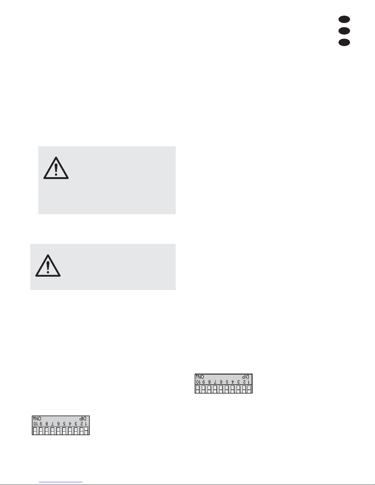
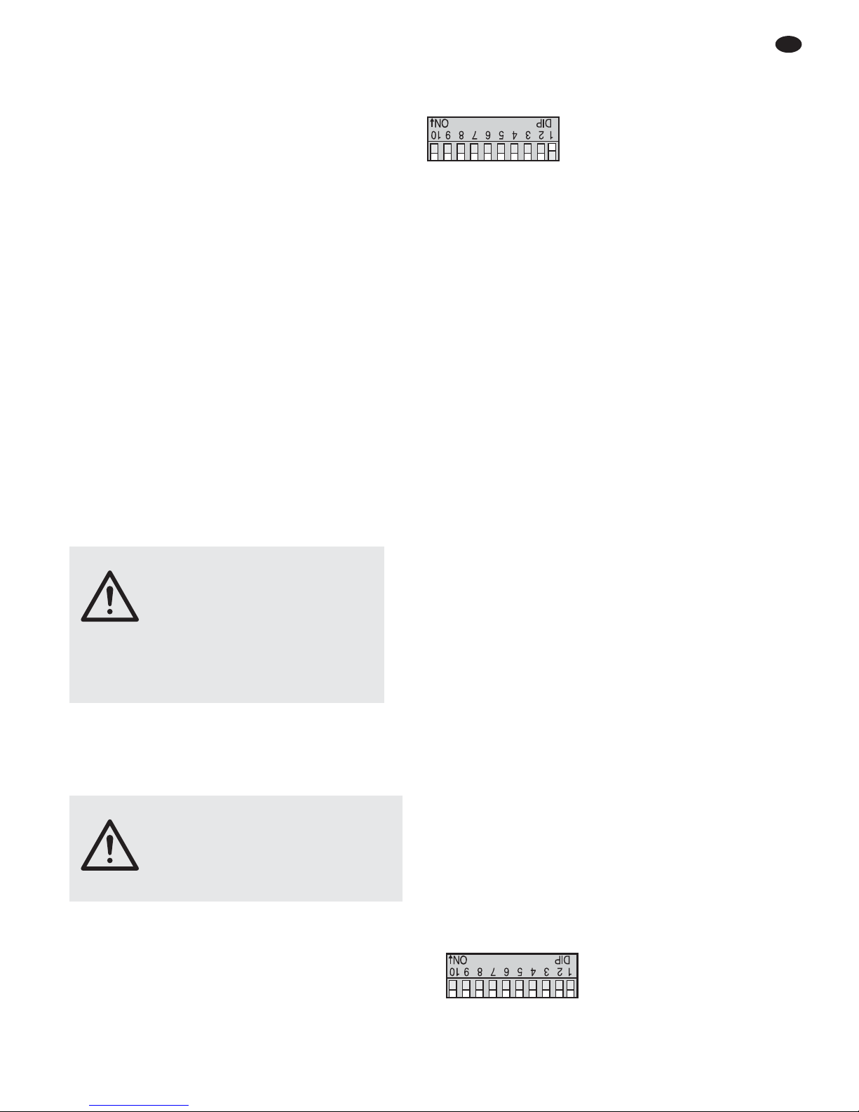
Den DIP-Schalter Nr. 1 (8) in die Position ON stellen,
alle anderen DIP-Schalter in die untere Position. Die
Kontroll-LED (9) leuchtet.
Abb. 4 Einstellung Master-Modus
Erhält das Lichteffektgerät kein DMX-Steuersignal,
leuchten die Lichtstrahlen auf. Die Kuppel dreht sich
und wechselt gelegentlich die Drehrichtung. Das
Modell LED-300DX/RGB wechselt zusätzlich die
Farbe der Lichtstrahlen.
Läuft Musik mit deutlichem Rhythmus im Bassbereich in ausreichender Lautstärke, wird über das interne
Mikrofon (5) die Drehrichtung, die Drehgeschwindigkeit, der Farbwechsel (nur bei LED-300DX/RGB) sowie
das Ein- und Ausschalten der Lichtstrahlen (nur bei
LED-300DX/WS) gesteuert. Bei jedem Musiksteuerimpuls erlischt kurz die Kontroll-LED (9). Sollte die
Musiksteuerung nicht optimal funktionieren, die Lautstärke erhöhen oder den Abstand zwischen Schallquelle und Lichteffektgerät verringern.
6.1 Konstante Drehrichtung und
Drehgeschwindigkeit
Soll sich die Kuppel mit einer konstanten Geschwindigkeit in eine Richtung drehen, auch den DIP-Schalter Nr. 2 (8) in die Position ON stellen. Nun lässt sich die
Drehrichtung mit dem Schalter Nr. 3 einstellen und die
Geschwindigkeit mit den Schaltern Nr. 4, 5, 6. Die Musiksteuerung über das Mikrofon (5) ist dabei ausgeschaltet.
6.2 Zusammenschalten mehrerer LED-300DX
Es lassen sich mehrere LED-300DX/RGB oder LED300DX/WS zusammenschalten, um so über das Mikrofon des Hauptgerätes (Master) alle weiteren Nebengeräte (Slave) im gleichen Rhythmus zu steuern.
1) Den Anschluss DMX OUTPUT (3) des Haupt -
gerätes über ein 3-poliges XLR-Kabel (z. B. Serie
MEC-... oder MECN-... aus dem Sortiment von „img
Stage Line“) mit dem Anschluss DMX INPUT (2)
des ersten Nebengerätes verbinden.
2) Den Anschluss DMX OUTPUT des ersten Neben-
gerätes mit dem Anschluss DMX INPUT des zwei-
ten Nebengerätes verbinden usw., bis alle Geräte in
einer Kette angeschlossen sind.
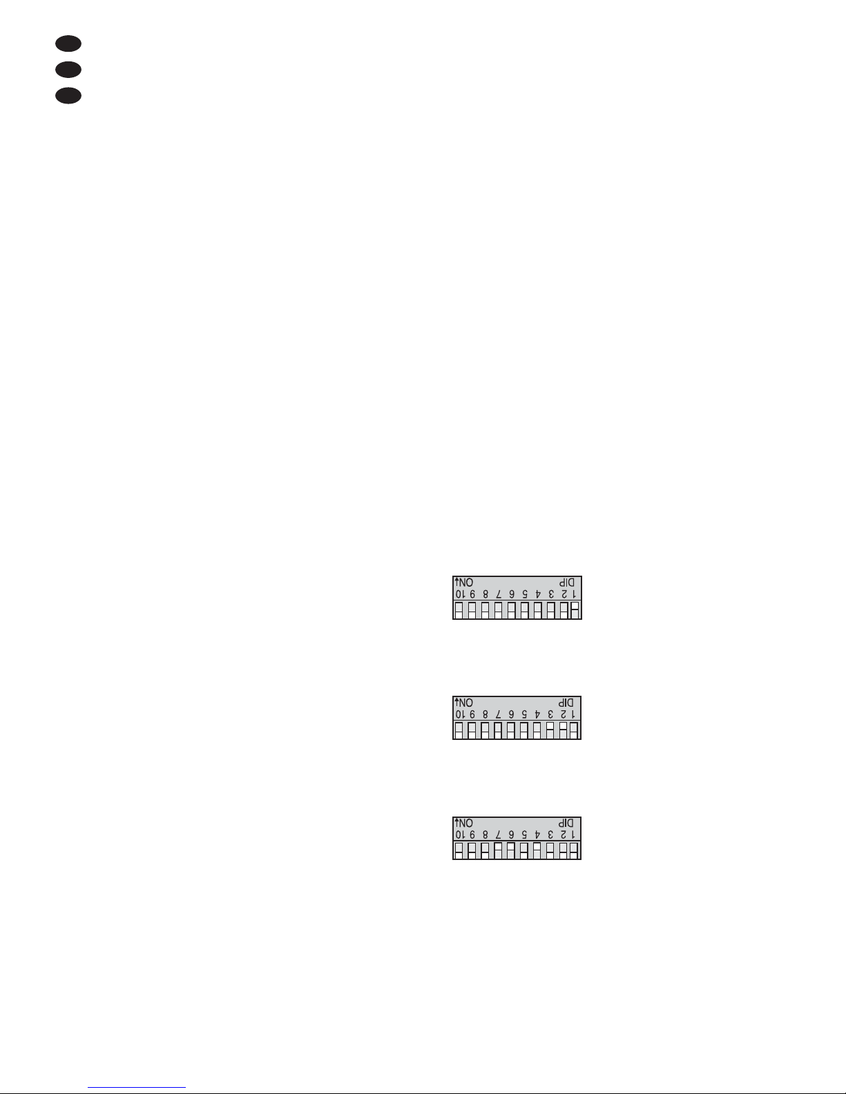
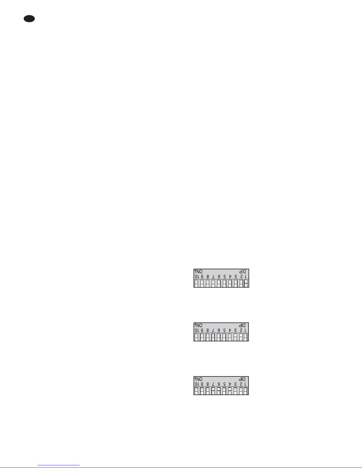
3) An den Nebengeräten die DIP-Schalter Nr. 1 – 9 (8)
alle in die untere Position (OFF) stellen. Sobald die
Nebengeräte die Steuersignale des Hauptgerätes
erhalten, leuchtet die Kontroll-LED (9) der Neben-
geräte alle 2 Sekunden kurz auf.
Abb. 5 Einstellung für die Nebengeräte (Slave-Modus)
4) Mit dem DIP-Schalter Nr. 10 (OPTION) kann an den
Nebengeräten gewählt werden, ob sie entgegen -
gesetzt zum Hauptgerät reagieren sollen (Schalter
auf ON) oder genau gleich (Schalter in die untere
Position).
WARNUNG Das Lichteffektgerät muss fachge-
recht und sicher montiert werden.
Wird es an einer Stelle installiert,
unter der sich Personen aufhalten
können, muss es zusätzlich gesichert werden (z. B. durch ein Fang seil; das Fangseil so befestigen,
dass der Fallweg des Gerätes nicht
mehr als 20 cm betragen kann).
OPTION
128
256643216842
1
OPTION
128
256643216842
1
WARNUNG Blicken Sie nicht direkt in den Lichtstrahl,
das kann zu Augenschäden führen.
Beachten Sie, dass sehr schnelle Lichtwechsel bei fotosensiblen Menschen
und Epilep tikern epileptische Anfälle
aus lösen können!
Page 6
6.3 Fernbedienung mit der LC-3
Über die als Zubehör erhältliche Fernbedienung LC-3
können verschiedene Funktionen gesteuert werden.
1) Die Fernbedienung an die Buchse ONLY FOR
REMOTE CONTROL (4) anschließen.
2) Am Eingang DMX INPUT (2) darf kein DMX-Signal
anliegen.
3) Über den Ausgang DMX OUTPUT (3) können weitere LED-300DX/RGB oder LED-300DX/WS angeschlossen werden (
Kapitel 6.2), um diese über
die Fernbedienung gemeinsam mit dem Hauptgerät zu steuern.
4) Mit der Taste STAND BY (10) lassen sich die Lichtstrahlen ein- und ausschalten. Bei ausgeschaltetem Licht leuchtet zur Kontrolle die LED neben der
Taste STAND BY auf.
5) Mit der Taste MODE (12) den Betriebsmodus wählen:
a) Leuchtet die LED der Taste MODE, ist der
Chase-Modus eingeschaltet. Durch kurzes Drücken der Taste FUNCTION (11) kann jetzt die
Drehgeschwindigkeit in acht Stufen gewählt
werden. Bei jedem Drücken der Taste ändert
sich gleichzeitig die Drehrichtung.
b) Leuchtet die LED der Taste MODE nicht, ist der
Stroboskop-Modus eingeschaltet. Durch Ge drückthalten der Taste FUNCTION lässt sich
eine der drei Stroboskop-Funktionen aktivieren:
1. Dauer-Stroboskop
2. Stroboskop in Salven
3. Musikabhängiges Stroboskop
(nur bei dem Modell LED-300DX/RGB)
Beim erneuten Gedrückthalten der Taste FUNC TION ist jeweils die nächste Stroboskop-Funktion aktiviert.
7 Bedienung über ein Lichtsteuergerät
Zur Bedienung über ein Lichtsteuergerät mit DMX512Protokoll (z. B. DMX-1440 oder DMX-510USB von
„img Stage Line“) verfügt das Modell LED-300DX/WS
über zwei DMX-Steuerkanäle und das Modell LED300DX/RGB über drei Steuerka näle. Die Funktionen
der Kanäle und die DMX-Werte finden Sie im Kap. 8.1.
7.1 Anschluss
Als DMX-Schnittstelle besitzt das Lichteffektgerät
3-po lige XLR-Buchsen mit folgender Kontaktbelegung:
Pin 1 = Masse, 2 = DMX
-
, 3 = DMX+
Zum Anschluss sollten spezielle Kabel für hohen
Datenfluss verwendet werden. Normale abgeschirmte
Mikrofonkabel mit einem Leitungsquerschnitt von mindestens 2 × 0,22 mm
2
und möglichst geringer Kapazität
sind nur bei einer Gesamtkabellänge bis 100 m zu empfehlen. Bei Leitungslängen ab 150 m wird grundsätzlich
das Zwischen schalten eines DMX-Aufholverstärkers
empfohlen (z. B. SR-103DMX von „img Stage Line“).
1) Den DMX-Eingang (2) mit dem DMX-Ausgang des
Lichtsteuergerätes verbinden.
2) Den DMX-Ausgang (3) mit dem DMX-Eingang des
nächsten Lichteffektgerätes verbinden. Dessen
Ausgang wieder mit dem Eingang des nachfolgenden Gerätes verbinden usw., bis alle Licht effektgeräte in einer Kette angeschlossen sind.
3) Den DMX-Ausgang des letzten DMX-Gerätes der
Kette mit einem 120-Ω-Widerstand (> 0,3 W) ab schließen: An die Pins 2 und 3 eines XLR-Steckers
den Widerstand anlöten und den Ste cker in den
DMX-Ausgang stecken oder einen entsprechenden
Abschlussstecker (z. B. DLT-123 von „img Stage
Line“) verwenden.
7.2 Startadresse einstellen
Um das LED-300DX/… mit einem Lichtsteuergerät be dienen zu können, muss die DMX-Startadres se für den
1. DMX-Kanal eingestellt werden. Ist z. B. am Steuer-
gerät die Adresse 17 zum Steuern des Lichteffektgerätes vorge sehen, am LED-300DX/RGB die Start adresse
17 einstellen. Die DMX-Kanäle 2 und 3 sind dann automatisch den beiden folgenden Adressen zugeordnet
(in diesem Beispiel 18 und 19). Als nächstmögliche
Startadresse für das folgende DMX-gesteuerte Gerät
könnte dann die Adresse 20 verwendet werden.
Die Startadresse wird als Binärzahl mit den DIP-
Schalter Nr. 1– 9 (8) eingestellt. Sie ergibt sich durch
die Addition der Stellenwerte der Schalter, die auf „ON“
gestellt sind.
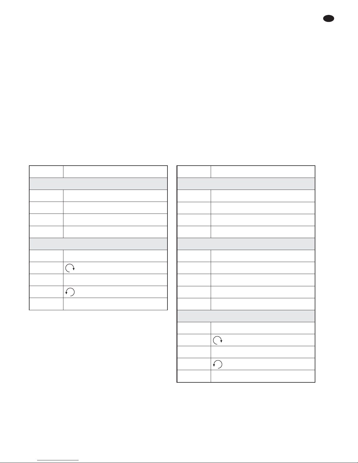
Beispiele für die Startadressen 1, 6 und 104:
Abb. 6 Startadresse 1: Schalter Nr. 1 auf ON
Abb. 7 Startadresse 6: Schalter Nr. 3 und 2 auf ON
Abb. 8 Startadresse 104: Schalter Nr. 7, 6 und 4 auf ON
Am einfachsten ist es, vom größtmöglichen Stellenwert auszugehen und die kleineren Werte dazuzuaddieren, bis sich als Summe die Startadresse ergibt.
Nach dem Einstellen der Startadresse lässt sich
das Lichteffektgerät über das DMX-Steuergerät bedienen. Sobald DMX-Signale empfangen werden, blinkt
die rote Kontroll-LED (9).
OPTION
128
256643216842
1
OPTION
128
256643216842
1
OPTION
128
256643216842
1
← Schalternummer
← Stellenwert
6
D
A
CH
Page 7
8 Technische Daten
Stromversorgung: . . . . . 230 V~ / 50 Hz
Leistungsaufnahme: . . . 25 VA
Leuchtmittel: . . . . . . . . . 1 superhelle LED, 3 W
LED-300DX/WS: . . . weiße LED
LED-300DX/RGB: . . RGB-LED
(rot, grün, blau)
Einsatztemperatur: . . . . 0 –40 °C
Abmessungen: . . . . . . . ∅220 × 190 mm
Gewicht: . . . . . . . . . . . . 1,8 kg
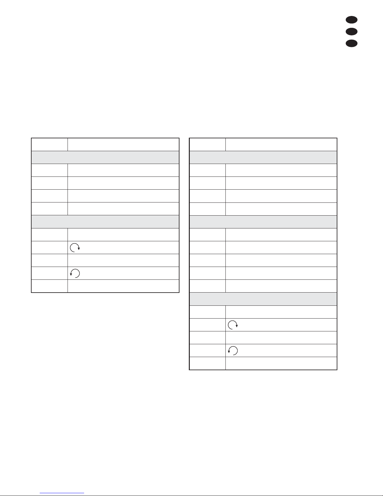
8.1 DMX-Kanäle
Modell LED-300DX/WS Modell LED-300DX/RGB
Änderungen vorbehalten.
DMX-Wert Funktion
Kanal 1: Dimmer / Stroboskop
0– 7 Licht aus
8 – 199
Dimmer: dunkel → hell
200 – 247
Stroboskop: schnell → langsam
248 – 255 maximale Helligkeit
Kanal 2: Farbe
0– 7 Farbe 1 (Grün)
8– 15 Farbe 2
16 – 23 Farbe 3
… …
248 – 255 Farbe 32 (Weiß)
Kanal 3: Rotation
0– 9 Stopp
10 – 120
schnell → langsam
121 – 134 Stopp
135 – 245
langsam → schnell
246 – 255 Stopp
DMX-Wert Funktion
Kanal 1: Dimmer / Stroboskop
0– 7 Licht aus
8 – 199
Dimmer: dunkel → hell
200 – 247
Stroboskop: langsam → schnell
248 – 255 maximale Helligkeit
Kanal 2: Rotation
0– 9 Stopp
10 – 120
schnell → langsam
121 – 134 Stopp
135 – 245
langsam → schnell
246 – 255 Stopp
7
D
A
CH
Diese Bedienungsanleitung ist urheberrechtlich für MONACOR®INTERNATIONAL GmbH & Co. KG ge schützt.
Eine Reproduktion für eigene kommerzielle Zwecke – auch auszugsweise – ist untersagt.
Page 8
All operating elements and connections described
can be found on page 2.
1 Operating Elements and Connections
1.1 Light effect unit LED-300DX/…
1 Mounting bracket
2 DMX signal input (3-pole XLR) for connecting a
light controller;
Pin 1 = ground, 2 = DMX
-
, 3 = DMX+
3 DMX signal output (3-pole XLR) for connection to
the DMX input of another DMX light effect unit;
Pin 1 = ground, 2 = DMX
-
, 3 = DMX+
4 Connection jack for the remote control LC-3
5 Microphone for music control
6 Support for the mains fuse
Always replace a fuse that has blown by one of the
same type.
7 Mains cable for connection to a socket (230 V~/
50 Hz)
8 DIP switches Nos. 1– 9 for adjusting the address of
the unit or the operating mode (master or slave
mode), DIP switch No. 10 for defining the behaviour in the slave mode (
chapter 6.2)
9 Indicating LED
– if it is permanently on:
no DMX or music control
– if it is extinguished to the beat of the music:
music control via the microphone (5)
– if it keeps flashing:
control via a DMX light controller
1.2 Remote control LC-3
The remote control is available as an accessory and
not supplied with the light effect unit.
10 Button STAND BY for deactivating the light beam
11 Button FUNCTION for selecting various functions
depending on the operating mode selected with the
button MODE (12)
12 Button MODE for switching over between
Stroboscope mode (LED of the button off)
Chase mode (LED of the button on)
Note: For control via the remote control, there must be no
DMX signal at the DMX INPUT (2).
2 Safety Notes
The unit corresponds to all required directives of the
EU and is therefore marked with .
Please observe the following items in any case:
G
The unit is suitable for indoor use only. Protect it
against dripping water and splash water, high air
humidity, and heat (admissible ambient temperature
range 0 – 40 °C).
G
Do not operate the unit or immediately disconnect
the mains plug from the mains socket
1. if the unit or the mains cable is visibly damaged,
2. if a defect might have occurred after the unit was
dropped or suffered a similar accident,
3. if malfunctions occur.
In any case the unit must be repaired by skilled personnel.
G
A damaged mains cable must be replaced by skilled
personnel only.
G
Never pull the mains cable for disconnecting the mains
plug from the mains socket, always seize the plug.
G
For cleaning only use a dry, soft cloth, never use
chemicals or water.
G
No guarantee claims for the unit and no liability for any
resulting personal damage or material damage will be
accepted if the unit is used for other purposes than
originally intended, if it is not safely mounted or correctly operated, or if it is not repaired in an expert way.
G
Important for U. K. Customers!
The wires in this mains lead are coloured in accord ance with the following code:
green/yellow = earth
blue = neutral
brown = live
As the colours of the wires in the mains lead of this
appliance may not correspond with the coloured
markings identifying the terminals in your plug, proceed as follows:
1. The wire which is coloured green and yellow must
be connected to the terminal in the plug which is
marked with the letter E or by the earth symbol ,
or coloured green or green and yellow.
2. The wire which is coloured blue must be connected to the terminal which is marked with the
letter N or coloured black.
3. The wire which is coloured brown must be connected to the terminal which is marked with the
letter L or coloured red.
Warning – This appliance must be earthed.
If the unit is to be put out of operation definitively, take it to a local recycling plant for a
disposal which is not harmful to the environment.
WARNING The unit uses dangerous mains voltage
(230 V~). Leave servicing to skilled personnel only and do not insert anything
into the air vents; inexpert handling may
result in electric shock.
8
GB
Page 9
3 Applications
The light effect unit is suited for applications on stage,
in discotheques or party rooms. Its light source is a
super bright LED (3 W) with a low power consumption
and a long life.
The light effect unit is designed for control via a
DMX light controller (LED-300DX/RGB with 3 DMX
control channels, LED-300DX/WS with 2 control channels); however, it can also be operated on its own or
with the remote control LC-3 available as an accessory.
4 Mounting
G
Always place the unit in such a way that a sufficient
air circulation will be ensured during operation.
Never cover the air vents on the housing.
G
The minimum distance to the illuminated object
should be 10 cm.
1) For mounting the light effect unit, fasten the two
mounting brackets (1) via four screws to a suitable
place.
2) For suspended mounting of the unit at a cross bar
or a lighting stand, screw the mounting angle pro-
vided via two screws to the two mounting brackets
(1). Screw the mounting angle with the unit to the
cross bar or to the lighting stand.
5 Setting the Light Effect Unit
into Operation
To switch on the unit, connect the plug of the mains
cable (7) to a mains socket (230 V~/50 Hz). To switch
it off, disconnect it from the socket.
For a more convenient operation, it is recommended to connect the unit to a mains socket which is
switched on and off via a light switch.
Caution: Do not connect the unit to the mains voltage
via a dimmer!
6 Operation without Controller
Set DIP switch No. 1 (8) to ON; set all other DIP
switches to the lower position. The indicating LED (9)
will light up.
Fig. 4 Adjustment of the master mode
If the light effect unit does not receive any DMX control
signal, the light beams will light up. The dome will start
rotating, occasionally changing its sense of rotation.
Model LED-300DX/RGB will additionally change the
colour of the light beams.
When music is played at sufficient volume with a
clear rhythm in the bass range, the sense of rotation,
the speed, the change of colour (for LED-300DX/RGB
only) and the activation/deactivation of the light beams
(for LED-300DX/WS only) will be controlled via the
internal microphone (5). With each music control
pulse, the indicating LED (9) will shortly be extinguished. If the music control should not work optimally,
increase the volume or reduce the distance between
the sound source and the light effect unit.
6.1 Constant sense of rotation and speed
For turning the dome at a constant speed in one direction, also set DIP switch No. 2 (8) to ON. Now it will be
possible to adjust the sense of rotation with DIP switch
No. 3 and the speed with the DIP switches Nos. 4, 5,
6. The music control via the microphone (5) will be
deactivated.
6.2 Interconnecting several LED-300DX units
Several LED-300DX/RGB or LED-300DX/WS units
may be interconnected in order to control all slave
units to the same rhythm via the microphone of the
master unit.
1) Connect the DMX OUTPUT (3) of the master unit
via a 3-pole XLR cable (e. g. series MEC-… or
MECN-… from the product range of “img Stage
Line”) to the DMX INPUT (2) of the first slave unit.
2) Connect the DMX OUTPUT of the first slave unit to
the DMX INPUT of the second slave unit, etc. until
all units have been connected in a chain.
3) On the slave units, set all DIP switches Nos. 1 – 9
(8) to the lower position (OFF). Once the slave units
receive the control signals of the master unit, the
indicating LED (9) of the slave units will shortly light
up every 2 seconds.
Fig. 5 Adjustment for the slave units (slave mode)
OPTION
128
256643216842
1
OPTION
128
256643216842
1
WARNING Never look directly into the light beam;
this may cause eye damage.
Please note that fast changes in lighting, e. g. flashing light, may trigger
epileptic seizures with photosensitive
persons or persons with epilepsy!
WARNING Mount the light effect unit safely and
expertly. If it is installed at a place
where people may walk or sit under
it, additionally secure it (e. g. by a
safety rope; fasten the safety rope in
such a way that, even in the event of
a fall, the maximum falling distance
of the light effect unit will not exceed
20 cm).
9
GB
Page 10
4) DIP switch No. 10 (OPTION) will define the behaviour of the slave units: opposite to the master unit
(switch set to ON) or identical to it (switch set to the
lower position).
6.3 Remote control LC-3
The remote control LC-3 available as an accessory
allows to control various functions.
1) Connect the remote control to the jack ONLY FOR
REMOTE CONTROL (4).
2) There must be no DMX signal at the DMX INPUT (2).
3) Via the DMX OUTPUT (3), further LED300DX/RGB or LED-300DX/WS units may be connected (
chapter 6.2) in order to control them
together with the master unit via the remote control.
4) The button STAND BY (10) allows to activate/deactivate the light beams. With the beams deactivated,
the LED next to the button STAND BY will light up.
5) Select the operating mode with the button MODE
(12).
a) When the LED of the button MODE is on, the
Chase mode will be activated. By shortly pressing the button FUNCTION (11), the rotation
speed can be selected in eight steps. Each time
the button is pressed, the sense of rotation will
change at the same time.
b) When the LED of the button MODE is off, the
Stroboscope mode will be activated. By keeping the button FUNCTION pressed, one of the
three stroboscope functions can be activated:
1. Permanent stroboscope
2. Stroboscope salvos
3. Music-dependent stroboscope
(for model LED-300DX/RGB only)
When the button FUNCTION is kept pressed
again, the next stroboscope function respectively will be activated.
7 Operation via a Light Controller
For operation via a light controller with DMX512 protocol (e. g. DMX-1440 or DMX-510USB by “img Stage
Line”), model LED-300DX/WS is equipped with 2 DMX
control channels and model LED-300DX/RGB with
3 control channels. The functions of the channels and
the DMX values can be found in chapter 8.1.
7.1 Connection
As a DMX interface, the light effect unit is provided with
3-pole XLR jacks of the following pin configuration:
Pin 1 = ground, 2 = DMX
-
, 3 = DMX+
For connection, special cables for high data flow should
be used. Standard microphone cables with screening
and a minimum cross section of 2 × 0,22 mm
2
and with
a capacity as low as possible can only be recommended for a total cable length of up to 100 m. For cable
lengths exceeding 150 m it is recommended to insert a
DMX level matching amplifier (e. g. SR-103DMX by
“img Stage Line”).
1) Connect the DMX input (2) to the DMX output of the
light controller.
2) Connect the DMX output (3) to the DMX input of the
following light effect unit; connect its output again to
the input of the following unit, etc. until all light effect
units have been connected in a chain.
3) Terminate the DMX output of the last DMX unit in
the chain with a 120 Ω resistor (> 0.3W): Solder the
resistor to the pins 2 and 3 of an XLR plug and connect the plug to the DMX output or use a corresponding terminating plug (e. g. DLT-123 by “img
Stage Line”).
7.2 Adjusting the start address
For operating the LED-300DX/…with a light controller,
adjust the DMX start address for the first DMX channel.
If e. g. address 17 on the controller is provided for controlling the light effect unit, adjust the start address 17
on the LED-300DX/RGB. For model LED-300DX/RGB,
the DMX channels 2 and 3 will then automatically be
assigned to the two following addresses (in this example 18 and 19). As the next possible start address for
the following DMX-controlled unit, address 20 could be
used in this example.
The start address is adjusted as a binary number
with the DIP switches Nos. 1 – 9 (8). It will result by
adding the place values of the switches set to “ON”.
Examples of the start addresses 1, 6 and 104:
Fig. 6 Start address 1: switch No. 1 set o ON
Fig. 7 Start address 6: switches Nos. 3 and 2 set to ON
Fig. 8 Start address 104: switches Nos. 7, 6 and 4 set to ON
The easiest way is to start from the highest possible
place value and to add the smaller values until the start
address will result.
OPTION
128
256643216842
1
OPTION
128
256643216842
1
OPTION
128
256643216842
1
← Switch number
← Place value
10
GB
Page 11
After adjusting the start address, the light effect unit
can be operated via the DMX controller. Once DMX
signals are received, the red indicating LED (9) will
start flashing.
8 Specifications
Power supply: . . . . . . . . 230 V~/50 Hz
Power consumption: . . . 25 VA
Light source: . . . . . . . . . 1 super bright LED, 3 W
LED-300DX/WS: . . . white LED
LED-300DX/RGB: . . RGB LED (red, green, blue)
Ambient temperature: . . 0 – 40 °C
Dimensions. . . . . . . . . . Ø 220 x 190mm
Weight: . . . . . . . . . . . . . 1.8 kg
8.1 DMX channels
Model LED-300DX/WS Model LED-300DX/RGB
Subject to technical modification.
DMX value Function
Channel 1: dimmer/stroboscope
0– 7 light off
8 – 199
dimmer: dark → bright
200 – 247
stroboscope: slow → fast
248 – 255 maximum brightness
Channel 2: rotation
0– 9 stop
10 – 120
fast → slow
121 – 134 stop
135 – 245
slow → fast
246 – 255 stop
DMX value Function
Channel 1: dimmer/stroboscope
0– 7 light off
8 – 199
dimmer: dark → bright
200 – 247
stroboscope: fast → slow
248 – 255 maximum brightness
Channel 2: colour
0– 7 colour 1 (green)
8– 15 colour 2
16 – 23 colour 3
… …
248 – 255 colour 32 (white)
Channel 3: rotation
0– 9 stop
10 – 120
fast → slow
121 – 134 stop
135 – 245
slow → fast
246 – 255 stop
11
GB
All rights reserved by MONACOR®INTERNATIONAL GmbH & Co. KG. No part of this instruction manual may
be reproduced in any form or by any means for any commercial use.
Page 12

Vous trouverez page 2, lʼensemble des éléments et
branchements.
1 Eléments et branchements
1.1 Jeu de lumière LED-300DX/...
1 Etrier de fixation
2 Entrée signal DMX (XLR 3 pôles) pour brancher un
jeu de lumière
Pin 1 = masse, 2 = DMX
-
, 3 = DMX +
3 Sortie signal DMX (XLR 3 pôles) pour brancher à
lʼentrée DMX dʼun autre jeu de lumière DMX
Pin 1 = masse, 2 = DMX
-
, 3 = DMX +
4 Prise de branchement de la télécommande LC-3
5 Microphone pour la gestion via la musique
6 Porte-fusible : tout fusible fondu doit être remplacé
impérativement par un fusible de même type.
7 Cordon secteur à brancher à une prise 230 V~ /
50 Hz
8 Interrupteurs DIP N°1– 9 pour régler lʼadresse de
lʼappareil ou le mode de fonctionnement (master
ou slave) ; interrupteur DIP N° 10 pour sélectionner
la réaction en mode Slave (voir chapitre 6.2)
9 LED de contrôle
– brille tout le temps :
pas de gestion DMX ou par la musique
– sʼéteint au rythme de la musique :
gestion par la musique via le microphone (5)
– clignote en continu :
gestion via un contrôleur DMX
1.2 Télécommande LC-3
La télécommande est disponible en option mais nʼest
pas livrée avec le jeu de lumière.
10 Touche STAND BY pour éteindre le faisceau
11 Touche FUNCTION pour sélectionner les diffé-
rentes fonctions selon le mode de fonctionnement
choisi avec la touche MODE (12)
12 Touche MODE pour commuter entre
mode Stroboscope (la LED de la touche ne brille
pas)
mode Chase (la LED de la touche brille)
Conseil : Pour une gestion via la télécommande, aucun
signal DMX ne doit pas être présent à lʼentrée DMX INPUT
(2).
2 Conseils dʼutilisation et de sécurité
Lʼappareil répond à toutes les directives nécessaires
de lʼUnion européenne et porte donc le symbole .
Respectez scrupuleusement les points suivants :
G
Lʼappareil nʼest conçu que pour une utilisation en
intérieur. Protégez-le de tout type de projections
dʼeau, des éclaboussures, dʼune humidité élevée
dʼair et de la chaleur (plage de température de fonctionnement autorisée : 0 – 40 °C).
G
Ne faites pas fonctionner lʼappareil ou débranchezle immédiatement du secteur lorsque :
1. des dommages visibles apparaissent sur lʼappareil ou sur le cordon secteur,
2. après une chute ou un cas similaire, vous avez un
doute sur lʼétat de lʼappareil,
3. des dysfonctionnements apparaissent.
Dans tous les cas, les dommages doivent être réparés par un technicien spécialisé.
G
Tout cordon secteur endommagé ne doit être remplacé que par un technicien habilité.
G
Ne débranchez jamais lʼappareil en tirant sur le cordon secteur ; retirez toujours le cordon secteur en
tirant la fiche.
G
Pour le nettoyage, utilisez seulement un chiffon sec
et doux, en aucun cas, de produits chimiques ou
dʼeau.
G
Nous déclinons toute responsabilité en cas de dommages matériels ou corporels résultants si lʼappareil
est utilisé dans un but autre que celui pour lequel il a
été conçu, sʼil nʼest pas correctement monté, utilisé
ou nʼest pas réparé par une personne habilitée, en
outre, la garantie deviendrait caduque.
3 Possibilités dʼutilisation
Le jeu de lumière est particulièrement adapté pour une
utilisation sur scène, en discothèque et dans des
salles de fêtes. Une LED très claire de 3 W est la
source de lumière, elle a une faible consommation et
une longue durée de vie.
Le jeu de lumière est conçu pour une gestion via un
contrôleur DMX (LED-300DX/ RGB avec 3 canaux de
commande DMX, LED-300DX/ WS avec 2 canaux de
commande DMX), il peut également fonctionner seul
ou avec la télécommande LC3, disponible en option.
Lorsque lʼappareil est définitivement retiré du
service, vous devez le déposer dans une
usine de recyclage adaptée pour contribuer à
son élimination non polluante.
AVERTISSEMENT Lʼappareil est alimenté par une
tension dangereuse 230 V~. Ne
touchez jamais lʼintérieur de lʼappareil et ne faites rien tomber
dans les ouïes de ventilation !
Risque de décharge électrique.
12
F
B
CH
Page 13

4 Montage
G
Placez toujours lʼappareil de telle sorte quʼune circulation dʼair suffisante soit assurée pendant le
fonctionnement. En aucun cas, les ouïes de ventilation sur le boîtier ne doivent être obturées.
G
La distance avec lʼobjet à éclairer devrait être de
10 cm au moins.
1) Vissez les deux étriers de fixation (1) avec quatre
vis à lʼendroit voulu pour monter le jeu de lumière.
2) Si lʼappareil doit être monté suspendu sur une traverse ou sur un pied, vissez lʼétrier de montage livré
avec deux vis sur les deux étriers de fixation (1).
Vissez lʼétrier de montage avec lʼappareil sur la traverse ou sur le pied.
5 Mise en service
Pour allumer lʼappareil, reliez la fiche du cordon secteur (7) à une prise 230 V~/ 50 Hz. Pour lʼéteindre, débranchez le cordon secteur.
Pour un meilleur confort dʼutilisation, il est recom-
mandé de relier lʼappareil à une prise secteur pouvant
être allumée et éteinte via un interrupteur.
Attention : Lʼappareil ne doit pas être relié à la tension
secteur via un dimmer !
6 Fonctionnement sans contrôleur
Mettez lʼinterrupteur DIP N°1 (8) sur la position ON,
tous les autres interrupteurs DIP sur la position inférieure, la LED de contrôle (9) brille.
Schéma 4 Réglage mode Master
Si le jeu de lumière ne reçoit pas de signal de commande DMX, les faisceaux brillent. Le dôme tourne sur
lui-même et change de temps en temps de sens de
rotation. Le modèle LED-300DX/ RGB change, en
plus, la couleur des faisceaux lumineux.
Si la musique a un rythme marqué dans la plage
des graves à un volume suffisant, la direction de rotation, la vitesse de rotation, le changement de couleur (uniquement pour LED-300DX/ RGB), lʼallumage/
extinction des faisceaux lumineux (uniquement pour
LED-300DX/ WS) sont gérés via le microphone interne
(5). A chaque impulsion de musique, la LED de
contrôle sʼéteint brièvement (9). Si la gestion via la
musique ne fonctionne pas correctement, augmentez
le volume ou diminuez la distance entre la source
sonore et le jeu de lumière.
6.1 Direction et vitesse de rotation constantes
Si le dôme doit tourner dans un sens avec une vitesse
constante, mettez également lʼinterrupteur DIP N°2 (8)
sur la position ON. On peut régler le sens de rotation
avec lʼinterrupteur N°3 et la vitesse avec les interrupteurs N°4, 5, 6. La gestion de la musique via le microphone (5) est alors désactivée.
6.2 Fonctionnement combiné de plusieurs
LED-300DX
Il est possible de faire fonctionner ensemble plusieurs
LED-300DX/ RGB ou LED-300DX/ WS pour contrôler
tous les appareils auxiliaires (Slave) au même rythme
via le microphone de lʼappareil principal (Master).
1) Reliez la connexion DMX OUTPUT (3) de lʼappareil
principal via un cordon XLR 3 pôles (par exemple
MEC-… ou MECN-… de la gamme “img Stage
Line”) à lʼentrée DMX INPUT (2) du premier appa-
reil auxiliaire.
2) Reliez la sortie DMX OUTPUT du premier appareil
auxiliaire à lʼentrée DMX INPUT du deuxième appa-
reil auxiliaire et ainsi de suite jusquʼà ce que tous
les appareils soient reliés en une chaîne.
3) Sur les appareils auxiliaires, réglez tous les inter-
rupteurs DIP N° 1 – 9 (8) sur la position inférieure
(OFF). Dès que les appareils auxiliaires reçoivent
les signaux de commande de lʼappareil principal, la
LED de contrôle (9) des appareils auxiliaires brille
brièvement toutes les 2 secondes.
Schéma 5 Réglage des appareils auxiliaires
(mode Slave)
4) Avec lʼinterrupteur DIP N° 10 (OPTION), on peut
sélectionner sur les appareils auxiliaires sʼils doi-
vent réagir de manière opposée à lʼappareil princi-
pal (interrupteur sur ON) ou fonctionner de la même
manière (interrupteur sur la position inférieure).
OPTION
128
256643216842
1
OPTION
128
256643216842
1
AVERTISSEMENT Ne regardez jamais directement
le faisceau lumineux, cela peut
générer des troubles de la vue.
Nʼoubliez pas que des changements très rapides de lumière
peuvent déclencher des crises
dʼépilepsie chez les personnes
photosensibles et épileptiques.
AVERTISSEMENT Lʼappareil doit être monté de
manière professionnelle et
sûre. Si lʼappareil doit être
suspendu au-dessus de personnes, il doit être en plus
assuré (p. ex. avec une corde
de sécurité. Fixez la corde de
telle sorte que la distance de
chute de lʼappareil ne puisse
pas être supérieure à 20 cm).
13
F
B
CH
Page 14

6.3 Fonctionnement avec télécommande LC-3
Via la télécommande LC-3 disponible en option,
diverses fonctions peuvent être gérées.
1) Reliez la télécommande à la prise ONLY FOR
REMOTE CONTROL (4).
2) Aucun signal DMX ne doit être présent à lʼentrée
DMX INPUT (2).
3) Via la sortie DMX OUTPUT (3), on peut brancher
dʼautres LED-300DX/ RGB ou LED-300DX/ WS
(voir chapitre 6.2) pour les gérer, via la télécommande, avec lʼappareil principal.
4) Avec la touche STAND BY (10), on peut allumer et
éteindre les faisceaux lumineux. La LED à côté de
la touche STAND BY brille et sert de contrôle
lorsque la lumière est éteinte.
5) Avec la touche MODE (12), sélectionnez le mode
de fonctionnement :
a) Si la LED de la touche MODE brille, le mode
Chase est activé. Par une brève pression sur la
touche FUNCTION (11), on peut sélectionner la
vitesse de rotation en 8 paliers. A chaque pression sur la touche, le sens de rotation se modifie
simultanément.
b) Si la LED de la touche MODE ne brille pas, le
mode Stroboscope est activé. En maintenant
la touche FUNCTION enfoncée, on peut activer
une des trois fonctions Stroboscope :
1. stroboscope continu
2. stroboscope en rafales
3. stroboscope fonction de la musique
(uniquement sur le modèle LED-300DX/ RGB)
Si vous maintenez une nouvelle fois la touche
FUNCTION enfoncée, la fonction stroboscope
suivante est activée.
7 Utilisation via un contrôleur
Pour une utilisation via un contrôleur avec protocole
DMX512 (par exemple DMX-1440 ou DMX-510USB
de “img Stage Line”), le modèle LED-300DX/ WS dispose de deux canaux de commande DMX et le LED300DX/ RGB de 3 canaux de commande. Les fonctions des canaux et les valeurs DMX sont décrites
dans le chapitre 8.1.
7.1 Branchement
Lʼappareil possède des connexions XLR 3 pôles avec
la configuration suivante pour lʼinterface DMX :
Pin 1 = masse, 2 = DMX
-
, 3 = DMX +
Pour le branchement, il est recommandé dʼutiliser des
câbles spécifiques pour des flots importants de données. Lʼemploi de câbles micro usuels avec blindage
et une section de 2 × 0,22 mm
2
au moins et la capacité
la plus faible possible ne nʼest recommandé que pour
des longueurs de câble de 100 m maximum. Pour des
longueurs de liaison à partir de 150 m, il est recommandé dʼinsérer un amplificateur DMX de signal (par
exemple SR-103DMX de “img Stage Line”).
1) Reliez lʼentrée DMX (2) à la sortie DMX du jeu de
lumière.
2) Reliez la sortie DMX (3) à lʼentrée DMX de lʼappareil suivant. Reliez sa sortie à lʼentrée du prochain
appareil et ainsi de suite jusquʼà ce que tous les
jeux de lumière soient reliés dans une chaîne.
3) Terminez la sortie DMX du dernier jeu de lumière de
la chaîne avec une résistance 120 Ω (> 0,3 W) :
soudez aux pins 2 et 3 dʼune fiche XLR la résistance et branchez la fiche dans la sortie DMX ou utilisez un bouchon correspondant (p. ex. DLT-123 de
“img Stage Line”).
7.2 Réglage de lʼadresse de démarrage
Pour pouvoir utiliser le LED-300DX/... avec un contrôleur, lʼadresse de démarrage DMX doit être réglée
pour le canal DMX 1. Si par exemple, sur le contrôleur,
lʼadresse 17 est utilisée pour gérer le jeu de lumière,
réglez lʼadresse de démarrage 17 sur le LED-300DX/
RGB. Les canaux DMX 2 et 3 sont automatiquement
attribués aux deux adresses suivantes (dans cet
exemple 18, 19). Comme adresse de démarrage
immédiatement suivante pour lʼappareil à gestion
DMX suivant, on pourrait, dans cet exemple, utiliser
lʼadresse 20.
Lʼadresse de démarrage est réglée, sous forme de
valeur binaire, avec les interrupteurs DIP N° 1 à 9 (8).
Elle sʼobtient en additionnant les valeurs de position
des interrupteurs DIP réglés sur “ON”.
Exemples pour les adresses de démarrage 1, 6 et 104 :
Schéma 6 Adresse de démarrage 1 : interrupteur N° 1 sur ON
Schéma. 7 Adresse de démarrage 6 : interrupteurs N° 3 et
2 sur ON
Schéma 8 Adresse de démarrage 104 : interrupteurs N° 7,
6 et 4 sur ON
Le plus simple est toujours de partir de la valeur de
position la plus grande et dʼy ajouter les valeurs plus
OPTION
128
256643216842
1
OPTION
128
256643216842
1
← numéro de lʼinterrupteur
← valeur de position
OPTION
128
256643216842
1
14
F
B
CH
Page 15

petites jusquʼà obtenir avec la somme lʼadresse de
démarrage.
Une fois lʼadresse de démarrage réglée, le jeu de
lumière peut être utilisé via le contrôleur DMX. Dès
que les signaux DMX sont reçus, la LED rouge de
contrôle (9) clignote.
8 Caractéristiques techniques
Alimentation : . . . . . . . . 230V~ / 50 Hz
Consommation : . . . . . . 25 VA
Lampe : . . . . . . . . . . . . 1 LED très claire, 3 W
LED-300DX / WS : . . . LED blanche
LED-300DX / RGB : . . LED RVB (rouge, vert, bleu)
Température fonc. : . . . 0 – 40 °C
Dimensions : . . . . . . . . ∅220 × 190 mm
Poids : . . . . . . . . . . . . . 1,8 kg
8.1 Canaux DMX
Modèle LED-300DX/WS
Modèle LED-300DX/RGB
Tout droit de modification réservé.
Valeur DMX Fonction
Canal 1: Dimmer/Stroboscope
0– 7 Lumière éteinte
8 – 199
Dimmer : sombre → clair
200 – 247
Stroboscope: rapide → lent
248 – 255 Luminosité maximale
Canal 2: Couleur
0– 7 Couleur 1 (vert)
8– 15 Couleur 2
16 – 23 Couleur 3
… …
248 – 255 couleur 32 (blanc)
Kanal 3: Rotation
0– 9 Arrêt
10 – 120
rapide → lent
121 – 134 Arrêt
135 – 245
lent → rapide
246 – 255 Arrêt
Valeur DMX Fonction
Canal 1: Dimmer/Stroboscope
0– 7 Lumière éteinte
8 – 199
Dimmer : sombre → clair
200 – 247
Stroboscope : lent → rapide
248 – 255 Luminosité maximale
Canal 2: Rotation
0– 9 Arrêt
10 – 120
rapide → lent
121 – 134 Arrêt
135 – 245
lent → rapide
246 – 255 Arrêt
15
F
B
CH
Notice dʼutilisation protégée par le copyright de MONACOR®INTERNATIONAL GmbH & Co. KG. Toute reproduction même partielle à des fins commerciales est interdite.
Page 16

A pagina 2 trovate tutti gli elementi di comando e
collegamenti descritti.
1 Elementi di comando e collegamenti
1.1 Unità per effetti di luce LED-300DX/…
1 Angoli di fissaggio
2 Ingresso segnale DMX (XLR a 3 poli) per il colle-
gamento di unʼunità di comando luce;
pin 1 = massa, 2 = DMX
-
, 3 = DMX+
3 Uscita segnale DMX (XLR a 3 poli) per il collega-
mento con lʼingresso DMX di unʼulteriore unità
DMX per effetti luce;
pin 1 = massa, 2 = DMX
-
, 3 = DMX+
4 Presa per il telecomando LC-3
5 Microfono per il comando musica
6 Portafusibile
Sostituire un fusibile difettoso sempre con uno
dello stesso tipo.
7 Cavo rete per il collegamento con un presa di rete
(230 V~/50 Hz)
8 DIP-switch n. 1 – 9 per impostare gli indirizzi degli
apparecchi oppure il modo di funzionamento
(master o slave)); DIP-switch n. 10 per scegliere la
reazione nel modo slave (
Capitolo 6.2)
9 LED di controllo
– rimane acceso:
nessun comando DMX o musica
– si spegne nel ritmo della musica:
comando musica tramite il microfono (5)
– lampeggia continuamente:
comando tramite unʼunità di comando luce DMX
1.2 Telecomando LC-3
Il telecomando LC-3 è disponibile come opzione e non
fa parte della dotazione dellʼunità per effetti di luce.
10 Tasto STAND BY per spegnere il raggio di luce
11 Tasto FUNCTION per scegliere le varie funzioni a
seconda del modo di funzionamento scelto con il
tasto MODE (12)
12 Tasto MODE per cambiare fra
modo stroboscopio (LED del tasto spento)
modo chase (LED del tasto acceso)
Nota: Per il comando tramite il telecomando, allʼingresso
DMX INPUT (4) non deve essere presente nessun segnale
DMX.
2 Avvertenze di sicurezza
Lʼapparecchio è conforme a tutte le direttive richieste
dellʼUE e pertanto porta la sigla .
Si devono osservare assolutamente anche i seguenti
punti:
G
Usare lʼapparecchio solo allʼinterno di locali e proteggerlo dallʼacqua gocciolante e dagli spruzzi dʼacqua, da alta umidità dellʼaria e dal calore (temperatura dʼimpiego ammessa fra 0 e 40 °C).
G
Non mettere in funzione lʼapparecchio e staccare
subito la spina rete se:
1. lʼapparecchio o il cavo rete presentano dei danni
visibili;
2. dopo una caduta o dopo eventi simili sussiste il
sospetto di un difetto;
3. lʼapparecchio non funziona correttamente.
Per la riparazione rivolgersi sempre ad unʼofficina
competente.
G
Il cavo rete, se danneggiato, deve essere sostituito
solo da un laboratorio specializzato
G
Staccare il cavo rete afferrando la spina, senza tirare
il cavo.
G
Per la pulizia usare solo un panno morbido, asciutto;
non impiegare in nessun caso prodotti chimici o
acqua.
G
Nel caso dʼuso improprio, di montaggio non sicuro,
dʼimpiego scorretto o di riparazione non a regola
dʼarte dellʼapparecchio, non si assume nessuna
responsabilità per eventuali danni consequenziali a
persone o a cose e non si assume nessuna garanzia per lʼapparecchio.
3 Possibilità dʼimpiego
Lʼunità per effetti di luce è indicata per lʼimpiego sul
palcoscenico, in discoteche e per party. Come sorgente di luce è equipaggiata con un LED superluminoso (3 Watt) che segna un basso consumo di corrente insieme ad una lunga durata.
Lʼunità per effetti di luce è prevista per il comando
attraverso unʼunità di comando luce DMX (LED300DX/RGB con tre canali di comando DMX, LED300DX/WS con due canali di comando DMX). Tuttavia, può essere usata anche da sola oppure tramite il
telecomando LC-3 disponibile come accessorio.
Se si desidera eliminare lʼapparecchio definitivamente, consegnarlo per lo smaltimento
ad unʼistituzione locale per il riciclaggio.
AVVERTIMENTO Lʼapparecchio funziona con peri-
colosa tensione di rete (230 V~).
Non intervenire mai al suo
interno e non inserire niente nelle
fessure di aerazione! Esiste il
pericolo di una scarica elettrica.
16
I
Page 17

4 Montaggio
G
Posizionare lʼapparecchio in modo tale che durante
il funzionamento sia garantita una circolazione sufficiente dellʼaria. Le aperture dʼaerazione sul contenitore non devono essere coperte in nessun caso.
G
La distanza dallʼoggetto irradiato deve essere non
inferiore a 10 cm.
1) Per il montaggio dellʼunità, avvitare i due angoli di
fissaggio (1) in un posto adatto servendosi di quattro viti.
2) Se lʼunità deve essere montata in modo sospeso ad
una traversa o ad uno stativo per fari, avvitare lʼangolo di montaggio in dotazione ai due angoli di fissaggio (1) per mezzo di due viti. Avvitare bene lʼangolo di montaggio insieme allʼunità alla traversa o
allo stativo per fari.
5 Messa in funzione
Per accendere lʼapparecchio, inserire la spina del cavo
rete (7) in un presa di rete (230 V~/50 Hz). Per spegnere, staccare la spina dalla presa di rete.
Per maggiore comodità conviene collegare lʼunità
con una presa comandata da un interruttore di luce.
Attenzione: Lʼapparecchio non deve essere collegato
con la tensione di rete per mezzo di un dimmer!
6
Funzionamento senza unità di comando
Portare il dip-switch n. 1 (8) in posizione ON, tutti gli
altri dip-switch in posizione inferiore. Si accende il LED
di controllo (9).
Fig. 4 Impostazione del modo Master
Se lʼunità per effetti di luce non riceve nessun segnale
di comando DMX, i raggi di luce si accendono. La
cupola gira e ogni tanto cambia senso di rotazione. Il
modello LED-300DX/RGB in più cambia il colore dei
raggi di luce.
In presenza di una musica con determinato ritmo
nei bassi e con volume sufficiente, tramite il microfono
interno (5) si comanda il senso e la velocità di rotazione, il cambio colori (solo con LED-300DX/RGB)
nonché lʼaccensione e lo spegnimento dei raggi di luce
(solo con LED-300DX/WS). Con ogni impulso di
comando musica, il LED di controllo (9) si spegne brevemente. Se il comando musica non dovesse funzionare perfettamente, aumentare il volume o ridurre la
distanza fra sorgente audio e unità per effetti di luce.
6.1 Senso e velocità di rotazione costanti
Se la cupola deve girare con velocità costante in una
direzione, portare anche il dip-switch n. 2 (8) in posizione ON. Ora è possibile impostare il senso di rotazione con lo switch n. 3 e la velocità con gli switch n. 4,
5, 6. Il comando musica per mezzo del microfono (5) è
disattivato in questo caso.
6.2 Assemblaggio di più unità LED-300DX
Si possono unire più unità LED-300DX/RGB o LED300DX/WS per comandare, tramite il microfono
interno dellʼapparecchio principale (Master), tutti gli
apparecchi secondari (Slave) nello stesso ritmo.
1) Collegare il contatto DMX OUTPUT (3) dellʼappa-
recchio principale con il contatto DMX INPUT (2)
del primo apparecchio secondario servendosi di un
cavo XLR a 3 poli (p. es. serie MEC-... o MECN-...
del programma di “img Stage Line”).
2) Collegare il contatto DMX OUTPUT del primo appa-
recchio secondario con il contatto DMX INPUT del
secondo apparecchio secondario ecc., finché tutti
gli apparecchi sono collegati formando una catena.
3) Sugli apparecchi secondari impostare tutti i dip-
switch n. 1 – 9 (8) in posizione inferiore (OFF). Non
appena gli apparecchi secondari ricevono dei
segnali di comando da parte dellʼapparecchio prin-
cipale, i LED di controllo (9) degli apparecchi secon-
dari si accendono brevemente ogni 2 secondi.
Fig. 5 Impostazione degli apparecchi secondari
(modo slave)
4) Con il dip-switch n. 10 (OPTION) è possibile deci-
dere sugli apparecchi secondari se devono reagire
in senso opposto rispetto allʼapparecchio principale
(switch su ON) oppure nello stesso senso (switch in
posizione inferiore).
OPTION
128
256643216842
1
OPTION
128
256643216842
1
AVVERTIMENTO Non guardare direttamente nella
sorgente di luce per escludere
possibili danni agli occhi.
Tenete presente che i veloci
cambi di luce possono provocare
attacchi dʼepilessia presso persone fotosensibili o epilettici!
AVVERTIMENTO Lʼunità deve essere montata a
regola dʼarte e in modo sicuro.
Se viene installata in un posto
sotto il quale si possono trattenere delle persone, è richiesto
un sistema di sicurezza supplementare (p. es. per mezzo
di una fune di trattenuta; fissare la fune in modo tale che
la caduta dellʼunità non possa
superare i 20 cm).
17
I
Page 18

6.3 Telecomando LC-3
Per mezzo del telecomando LC-3 disponibile come
accessorio è possibile comandare diverse funzioni.
1) Collegare il telecomando con la presa ONLY FOR
REMOTE CONTROL (4).
2) Allʼingresso DMX INPUT (2) non deve essere presente nessun segnale DMX.
3) Attraverso lʼuscita DMX OUTPUT (3) è possibile collegare ulteriori LED-300DX/RGB o LED-300DX/WS
(
Capitolo 6.2), per comandarli insieme con lʼap-
parecchio principale per mezzo del telecomando.
4) Con il tasto STAND BY (10) si possono spegnere e
riaccendere i raggi di luce. Con la luce spenta, per un
controllo si accende il LED vicino al tasto STAND BY.
5) Con il tasto MODE (12) selezionare il modo di funzionamento:
a) Se è acceso il LED del tasto MODE, è attivato il
modo Chase. Con una breve pressione del
tasto FUNCTION (11) è ora possibile modificare
la velocità di rotazione a 8 livelli. Con ogni pressione del tasto cambia contemporaneamente il
senso di rotazione.
b) Se non è acceso il LED del tasto MODE, è atti-
vato il modo Stroboscopio. Tenendo premuto il
tasto FUNCTION, si può attivare una delle tre
funzioni stroboscopiche:
1. stroboscopio permanente
2. stroboscopio a salve
3. stroboscopio dipendente dalla musica
(solo con il modello LED-300DX/RGB)
Tenendo nuovamente premuto il tasto FUNCTION,
è attivata sempre la funzione stroboscopica successiva.
7 Funzionamento attraverso unʼunità di
comando luce
Per il funzionamento attraverso unʼunità di comando
luce con protocollo DMX512 (p. es. DMX-1440 o
DMX-510USB di “img Stage Line”), il modello LED300DX/WS dispone di due canali di comando DMX e
il modello LED-300DX/RGB di tre canali di comando.
Le funzioni dei canali e i valori DMX si trovano nel capitolo 8.1.
7.1 Collegamento
Come interfaccia DMX, lʼunità possiede delle prese
XLR a 3 poli con i seguenti contatti:
pin 1 = massa, 2 = DMX
-
, 3 = DMX+
Per il collegamento si dovrebbero usare cavi per un
forte flusso di dati. Lʼimpiego di normali cavi schermati
per microfoni con sezione minima di 2 × 0,22 mm
2
e
con capacità possibilmente ridotta è consigliabile solo
nel caso di una lunghezza complessiva inferiore a
100 m. Nel caso di lunghezze oltre i 150 m si consiglia
lʼimpiego di un amplificatore DMX (p. es. SR-103DMX
di “img Stage Line”).
1) Collegare lʼingresso DMX (2) con lʼuscita DMX dellʼunità di comando.
2) Collegare lʼuscita DMX (3) con lʼingresso DMX della
successiva unità per effetti luce. Quindi collegare
lʼuscita di questʼultima con lʼingresso dellʼapparecchio a valle ecc. fino al collegamento di tutte le unità
in una catena.
3) Terminare lʼuscita DMX dellʼultima unità DMX della
catena con un resistenza 120 Ω (> 0,3 W): saldare
la resistenza ai pin 2 e 3 di un connettore XLR ed
inserire il connettore nellʼuscita DMX, oppure usare
un relativo connettore terminatore (p. es. DLT-123
di “img Stage Line”).
7.2 Impostare lʼindirizzo di start
Per poter usare il LED-300DX/… con unʼunità di
comando luce, occorre impostare lʼindirizzo di start
DMX per il primo canale DMX. Se, per esempio, sullʼunità di comando è previsto lʼindirizzo 17 per comandare lʼunità per effetti di luce, si deve impostare sul
LED-300DX/RGB lʼindirizzo di start 17. I canali DMX 2
e 3 sono così assegnati automaticamente ai due indirizzi successivi (nel nostro esempio 18 e 19). Come
prossimo indirizzo di start possibile per lʼapparecchio
DMX successivo si potrebbe quindi prendere nel
nostro esempio lʼindirizzo 20.
Lʼindirizzo di start viene impostato come numero
binario per mezzo dei DIP-switch n. 1 – 9 (8). Risulta
dallʼaddizione dei valori dei DIP-switch messi su ON.
Esempi per gli indirizzi di start 1, 6 e 104:
Fig. 6 Indirizzo di start 1: Switch n. 1 su ON
Fig. 7 Indirizzo di start 6: Switch n. 3 e 2 su ON
Fig. 8 Indirizzo di start 104: Switch n. 7, 6 e 4 su ON
Il sistema più semplice è di partire sempre dal massimo valore possibile aggiungendo i valori minori fino a
raggiungere, come somma, lʼindirizzo di start.
Dopo lʼimpostazione dellʼindirizzo di start, lʼunità per
effetti di luci può essere comandata tramite lʼunità di
comando DMX. Non appena riceve dei segnali DMX, il
LED rosso di controllo (9) lampeggia.
OPTION
128
256643216842
1
OPTION
128
256643216842
1
← Numero switch
← Valore
OPTION
128
256643216842
1
18
I
Page 19

8 Dati tecnici
Alimentazione: . . . . . . . 230 V~/50 Hz
Potenza assorbita: . . . . 25 VA
Lampadina: . . . . . . . . . 1 LED superluminoso, 3 W
LED-300DX/WS: . . . LED bianco
LED-300DX/RGB: . . LED RGB
(rosso, verde, blu)
Temperatura dʼesercizio: 0 – 40 °C
Dimensioni: . . . . . . . . . ∅ 220 × 190 mm
Peso : . . . . . . . . . . . . . . 1,8 kg
8.1 Canali DMX
Modello LED-300DX/WS Modello LED-300DX/RGB
Con riserva di modifiche tecniche.
Valore DMX Funzione
Canale 1: Dimmer/stroboscopio
0– 7 Luce spenta
8 – 199
Dimmer: scuro → chiaro
200 – 247
Stroboscopio: veloce → lento
248 – 255 Luminosità massima
Canale 2: Colore
0– 7 Colore 1 (verde)
8– 15 Colore 2
16 – 23 Colore 3
… …
248 – 255 Colore 32 (bianco)
Canale 3: Rotazione
0– 9 Stop
10 – 120
veloce → lento
121 – 134 Stop
135 – 245
lento → veloce
246 – 255 Stop
Valore DMX Funzione
Canale 1: Dimmer/stroboscopio
0– 7 Luce spenta
8 – 199
Dimmer: scuro → chiaro
200 – 247
Stroboscopio: lento → veloce
248 – 255 Luminosità massima
Canale 2: Rotazione
0– 9 Stop
10 – 120
veloce → lento
121 – 134 Stop
135 – 245
lento → veloce
246 – 255 Stop
19
I
La MONACOR®INTERNATIONAL GmbH & Co. KG si riserva ogni diritto di elaborazione in qualsiasi forma delle
presenti istruzioni per lʼuso. La riproduzione – anche parziale – per propri scopi commerciali è vietata.
Page 20

Op pagina 2 vindt u een overzicht van alle bedieningselementen en de aansluitingen.
1 Overzicht van de bedienings-
elementen en aansluitingen
1.1 Lichteffectapparaat LED-300DX /…
1 Hoekbeugel
2 DMX-signaalingang (3-polige XLR) voor het aan-
sluiten van een lichtregelaar;
pen 1 = massa, 2 = DMX
-
, 3 = DMX+
3 DMX-signaaluitgang (3-polige XLR) om een ander
DMX-lichteffectapparaat op de DMX-ingang aan te
sluiten;
pen 1 = massa, 2 = DMX
-
, 3 = DMX+
4 Aansluitjack voor de afstandsbediening LC-3
5 Microfoon voor muzieksturing
6 Houder voor de netzekering
Vervang een gesmolten zekering uitsluitend door
een zekering van hetzelfde type.
7 Netsnoer voor aansluiting op een stopcontact
(230 V~/50 Hz)
8 DIP-schakelaars nr. 1 – 9 voor het instellen van het
apparaatadres of van de bedrijfsmodus (master- of
slavemodus); DIP-schakelaar nr. 10 voor het selecteren van de reactie in de slavemodus (
hoofd-
stuk 6.2)
9 Controle-LED
– licht continu op:
geen DMX- of muzieksturing
– gaat uit op het ritme van de muziek:
muzieksturing via de microfoon (5)
– knippert continu:
besturing via een DMX-lichtregelaar
1.2 Afstandsbediening LC-3
De afstandsbediening is als toebehoren verkrijgbaar
en is niet in de levering van de lichtregelaar inbegrepen.
10 Toets STAND BY om de lichtbundel uit te schake-
len
11 Toets FUNCTION voor het selecteren van verschil-
lende functies afhankelijk van de bedrijfsmodus die
met de toets MODE (12) werd geselecteerd
12 Toets MODUS voor het wisselen tussen
stroboscoopmodus (LED van de toets licht niet op)
chasemodus (LED van de toets licht op)
Opmerking: Voor de besturing via de afstandsbediening
mag er geen DMX-signaal naar de ingang DMX INPUT (2)
worden gestuurd.
2 Veiligheidsvoorschriften
Het apparaat is in overeenstemming met alle vereiste
EU-Richtlijnen en is daarom gekenmerkt met .
Let eveneens op het volgende:
G
Het apparaat is enkel geschikt voor gebruik binnenshuis; vermijd druip- en spatwater, plaatsen met
een hoge vochtigheid en uitzonderlijk warme plaatsen (toegestaan omgevingstemperatuurbereik:
0 – 40 °C).
G
Schakel het apparaat niet in of trek onmiddellijk de
stekker uit het stopcontact,
1. wanneer het apparaat of het netsnoer zichtbaar
beschadigd is,
2. wanneer er een defect zou kunnen optreden
nadat het apparaat bijvoorbeeld is gevallen,
3. wanneer het apparaat slecht functioneert.
Het apparaat moet in elk geval worden hersteld door
een gekwalificeerd vakman.
G
Een beschadigd netsnoer mag alleen in een
erkende werkplaats worden vervangen.
G
Trek de stekker nooit met het snoer uit het stopcontact, maar steeds met de stekker zelf.
G
Verwijder het stof met een droge, zachte doek.
Gebruik zeker geen water of chemicaliën.
G
In geval van ongeoorloofd of verkeerd gebruik,
onveilige montage, foutieve bediening of van herstelling door een niet-gekwalificeerd persoon vervalt
de garantie en de aansprakelijkheid voor hieruit
resulterende materiële of lichamelijke schade.
3 Toepassingen
Het lichteffectapparaat is geschikt voor gebruik op
podia, in discotheken of in feestzalen. Als lamp wordt
een superheldere LED (3 watt) gebruikt. Deze heeft
een gering stroomverbruik en een lange levensduur.
Het lichteffectapparaat is ontworpen voor het besturen via een DMX-lichtregelaar (LED-300DX/RGB met
drie DMX-besturingskanalen, LED-300DX/WS met
twee DMX-besturingskanalen). Het apparaat kan ook
afzonderlijk worden bediend of met via de afstandsbediening LC-3 die als toebehoren verkrijgbaar is.
Wanneer het apparaat definitief uit bedrijf
wordt genomen, bezorg het dan voor milieuvriendelijke verwerking aan een plaatselijk
recyclagebedrijf.
WAARSCHUWING De netspanning (230V~) van het
apparaat is levensgevaarlijk.
Open het apparaat niet, en zorg
dat u niets in de ventilatieopeningen steekt! U loopt het risico
van een elektrische schok.
20
NL
B
Page 21

4 Montage
G
Plaats het apparaat steeds zo, dat bij het gebruik
voldoende ventilatie is gegarandeerd. De ventilatieopeningen in de behuizing mogen in geen geval zijn
afgedekt.
G
De afstand tot het bestraalde voorwerp moet ten
minste 10 cm bedragen.
1) Voor de montage van het lichteffectapparaat
schroeft u de beide hoekbeugels (1) op een
geschikte plaats met vier schroeven vast.
2) Als het apparaat aan een brug of op een lichtstatief
moet worden gemonteerd, schroeft u de bijgeleverde montagebeugel met twee schroeven op de
beide hoekbeugels (1) vast. Schroef de montagebeugel met het apparaat aan de brug resp. op het
lichtstatief vast.
5 Ingebruikneming
Voor het inschakelen van het lichteffectapparaat plugt
u de stekker van het netsnoer (7) in een stopcontact
(230 V~ / 50 Hz); om het apparaat uit te schakelen, trekt
u de stekker er terug uit.
Voor een makkelijker bediening is het aangeraden
het apparaat in een stopcontact te pluggen dat u via
een lichtschakelaar kan in- en uitschakelen.
Opgelet: Het apparaat mag niet via een dimmer op de
netspanning zijn aangesloten!
6 Gebruik zonder besturingsapparaat
Zet de DIP-schakelaar nr. 1 (8) in de stand ON, en alle
andere DIP-schakelaars in de onderste stand. De controle-LED (9) licht op.
Fig. 4 De mastermodus instellen
Als het lichteffectapparaat geen DMX-besturingssignaal ontvangt, dan lichten de lichtbundels op. De koepel draait en wisselt af en toe van draairichting. Het
model LED-300DX/RGB wisselt bovendien de kleur
van de lichtbundels.
Als er muziek wordt gespeeld met een duidelijk
ritme in het basbereik en met een voldoende geluidsvolume, dan wordt via de interne microfoon (5) de
draairichting, de draaisnelheid, de kleurwisseling
(alleen bij LED-300DX/RGB) evenals het in- en uitschakelen van de lichtbundels (alleen bij LED300DX/WS) gestuurd. Bij elke muziekstuurimpuls gaat
de controle-LED (9) even uit. Als de muzieksturing niet
optimaal zou functioneren, verhoogt u het geluidsvolume of verkort u de afstand tussen geluidsbron en het
lichteffectapparaat.
6.1 Constante draairichting en draaisnelheid
Als de koepel met een constante snelheid in een richting moet draaien, zet u ook de DIP-schakelaar nr. 2
(8) in de stand ON. Nu kunt u de draairichting met
schakelaar nr. 3 instellen en de snelheid met de schakelaars nr. 4, 5, 6. De muzieksturing via de microfoon
(5) is daarbij uitgeschakeld.
6.2 Meerdere LED-300DX-apparaten
aaneenschakelen
U kunt meerdere LED-300DX/RGB- of LED-300DX/WSapparaten aaneenschakelen, om zo via de microfoon
van het centrale apparaat (master) alle overige randapparaten (slave) op hetzelfde ritme te besturen.
1) Verbind de aansluiting DMX OUTPUT (3) van het
centrale apparaat via een 3-polige XLR-kabel (b.v.
serie MEC-... of MECN-... uit het gamma van “img
Stage Line”) met de aansluiting DMX INPUT (2) van
het eerste randapparaat.
2) Verbind de aansluiting DMX OUTPUT van het eer-
ste randapparaat met de aansluiting DMX INPUT
van het tweede randapparaat etc. tot alle apparaten
in een ketting aangesloten zijn.
3) Zet de DIP-schakelaars nr. 1 – 9 (8) op de neven-
apparaten allemaal in de onderste stand (OFF).
Zodra de nevenapparaten de besturingssignalen
van het centrale apparaat ontvangen, licht op con-
trole-LED (9) van de nevenapparaten om de twee
seconden op.
Fig. 5 Instelling voor de nevenapparaten (slavemodus)
OPTION
128
256643216842
1
OPTION
128
256643216842
1
WAARSCHUWING Kijk niet rechtstreeks in de licht-
bundel, omdat dit de ogen kan
beschadigen.
Weet dat stroboscoopeffecten
en zeer snelle lichtwisselingen
bij fotosensibele mensen en epileptici epileptische aanvallen
kunnen veroorzaken!
WAARSCHUWING Het Lichteffectapparaat moet
deskundig en veilig worden
gemonteerd. Als het op een
plek wordt geïnstalleerd,
waar personen onder kunnen
komen staan, moet het extra
worden beveiligd (b.v. door
een hijskabel; bevestig de
hijskabel zo dat het apparaat
niet meer dan 20 cm kan
vallen).
21
NL
B
Page 22

4) Met de DIP-schakelaar nr. 10 (OPTIE) kunt u op de
nevenapparaten selecteren, of ze tegengesteld aan
(schakelaar op ON) of juist identiek als (schakelaar
in de onderste stand) het centrale apparaat moeten
reageren.
6.3 Afstandsbediening met de LC-3
Via de als toebehoren verkrijgbare afstandsbediening
LC-3 kunnen verschillende functies worden gestuurd.
1) Sluit de afstandsbediening aan op de jack ONLY
FOR REMOTE CONTROL (4).
2) Op de ingang DMX INPUT (2) mag geen DMX-signaal beschikbaar zijn.
3) Via de uitgang DMX OUTPUT (3) kunnen andere
LED-300DX/RBG- of LED-300DX/WS-apparaten
worden aangesloten (
hoofdstuk 6.2), om deze
via de afstandsbediening samen met het centrale
apparaat te besturen.
4) Met de toets STAND BY (10) kunt u de lichtstralen
in- en uitschakelen. Als de lichtstralen zijn uitgeschakeld, licht ter controle de LED naast de toets
STAND BY op.
5) Selecteer met de toets MODE (12) de bedrijfsmodus:
a) Als de LED van de toets MODE oplicht, is de
chasemodus ingeschakeld. Door even op de
toets FUNCTION (11) te drukken, kunt u de
draaisnelheid nu op een van de acht niveaus
instellen. Telkens u op de knop drukt, wijzigt
tegelijk de draairichting.
b) Als de LED van de toets MODE niet oplicht, dan
is de stroboscoopmodus ingeschakeld. Door
de toets FUNCTION ingedrukt te houden, kunt u
een van de drie stroboscoopfuncties activeren:
1. Continu stroboscoop
2. Stroboscoop in salvoʼs
3. Muziekafhankelijke stroboscoop
(alleen bij model LED-300DX/RGB)
Telkens u de toets FUNCTION ingedrukt houdt,
wordt de volgende stroboscoopfunctie geactiveerd.
7 Bediening via een lichtregelaar
Voor het bedienen via een lichtbesturingsapparaat met
DMX512-protocol (b.v. DMX-1440 of DMX-510USB
van “img Stage Line”) beschikt het model LED300DX/WS over twee DMX-besturingskanalen en het
model LED-300DX/RGB over drie besturingskanalen.
De functies van de kanalen en de DMX-waarden vindt
u terug in hoofdstuk 8.1.
7.1 Aansluiting
Als DMX-interface heeft de lichteffectapparaat 3-polige
XLR-jacks met volgende penconfiguratie:
pen 1 = massa, 2 = DMX
-
, 3 = DMX+
Voor de aansluiting moeten speciale kabels voor hoge
gegevensstromen worden gebruikt. Normale afgeschermde microfoonkabels met een leidingdiameter
van ten minste 2 × 0,22 mm² en een zo gering mogelijke capaciteit zijn alleen bij een totale kabellengte tot
100 m aan te bevelen. Bij kabellengten vanaf 150 m
wordt in principe aanbevolen om een DMX-ophaalversterker tussen te schakelen (b.v. SR-103DMX van
“img Stage Line”).
1) Verbind de DMX-ingang (2) met de DMX-uitgang
van de lichtregelaar.
2) Verbind de DMX-uitgang (3) met de DMX-ingang
van het volgende lichteffectapparaat. Verbind de
uitgang hiervan opnieuw met de ingang van het
nageschakelde apparaat etc., tot alle lichteffectapparaten in een ketting zijn aangesloten.
3) Sluit de DMX-uitgang van het laatste DMX-apparaat
in de ketting af met een weerstand van 120 Ω (>
0,3 W): Soldeer de weerstand vast aan de pinnen 2
en 3 van een XLR-stekker en plug de stekker in de
DMX-uitgang, of gebruik een overeenkomstige
afsluitstekker (b.v. DLT-123 van “img Stage Line”).
7.2 Het startadres instellen
Om de LED-300DX/... met een lichtregelaar te kunnen
bedienen, moet het DMX-startadres voor het eerste
DMX-kanaal worden ingesteld. Indien b.v. op het besturingsapparaat het adres 17 voor het besturen van het
lichteffectapparaat is voorzien, stel dan op de LED300DX/RGB het startadres 17 in. De DMX-kanalen 2 en
3 zijn dan automatisch aan de volgende adressen toegewezen (in dit voorbeeld 18 en 19). Als eerstvolgend
mogelijke startadres voor het volgende DMX-gestuurde
apparaat zou het adres 20 kunnen worden gebruikt.
Het startadres wordt als binair getal met de DIP-
schakelaars nr. 1– 9 (8) ingesteld. Het adres wordt
bekomen door de plaatswaarden op te tellen van de
schakelaars die in de stand ON staan.
Voorbeelden voor startadressen 1, 6 en 104:
Fig. 6 Startadres 1: schakelaar nr. 1 op ON
Fig. 7 Startadres 6: schakelaars nr. 3 en nr. 2 op ON
Fig. 8 Startadres 104: schakelaars nr. 7, 6 en 4 op ON
OPTION
128
256643216842
1
OPTION
128
256643216842
1
OPTION
128
256643216842
1
← schakelaarnummer
← plaatswaarde
22
NL
B
Page 23

Het is het makkelijkst om uit te gaan van de grootst
mogelijke plaatswaarde en de kleinere waarden erbij
op te tellen: de resulterende som is dan het startadres.
Na het instellen van het startadres kunt u het lichteffectapparaat via het DMX-besturingsapparaat bedienen. Zodra de DMX-signalen worden ontvangen, knippert de rode controle-LED (9).
8 Technische gegevens
Voedingsspanning: . . . . 230 V~/50 Hz
Vermogensverbruik: . . . 25 VA
Lamp: . . . . . . . . . . . . . . 1 superheldere LED, 3 W
LED-300DX / WS: . . . witte LED
LED-300DX / RGB: . . RGB-LED
(rood, groen, blauw)
Omgevings-
temperatuurbereik: . . . . 0 – 40 °C
Afmetingen: . . . . . . . . . ∅ 220 × 190 mm
Gewicht: . . . . . . . . . . . . 1,8 kg
8.1 DMX-kanalen
Model LED-300DX / WS
Model LED-300DX/RGB
Wijzigingen voorbehouden.
DMX-waarde Functie
Kanaal 1: Dimmer/stroboscoop
0– 7 Licht uit
8 – 199
Dimmer: donker → helder
200 – 247
Stroboscoop: snel → langzaam
248 – 255 maximale helderheid
Kanaal 2: kleur
0– 7 kleur 1 (groen)
8– 15 kleur 2
16 – 23 kleur 3
… …
248 – 255 kleur 32 (wit)
Kanaal 3: Rotatie
0– 9 Stop
10 – 120
snel → langzaam
121 – 134 Stop
135 – 245
langzaam → schnell
246 – 255 Stop
DMX-waarde Functie
Kanaal 1: Dimmer/stroboscoop
0– 7 Licht uit
8 – 199
Dimmer: donker → helder
200 – 247
Stroboscoop: langzaam → snel
248 – 255 maximale helderheid
Kanaal 2: Rotatie
0– 9 Stop
10 – 120
snel → langzaam
121 – 134 Stop
135 – 245
langzaam → snel
246 – 255 Stop
23
Deze gebruiksaanwijzing is door de auteurswet beschermd eigendom van MONACOR®INTERNATIONAL
GmbH & Co. KG. Een reproductie – ook gedeeltelijk – voor eigen commerciële doeleinden is verboden.
NL
B
Page 24

Todos los elementos de funcionamiento y las
conexiones que se describen pueden encontrarse
en la página 2.
1 Elementos de Funcionamiento
y Conexiones
1.1 Juego de luces LED-300DX/…
1 Soporte de montaje
2 Entrada de señal DMX (XLR 3 polos) para conec-
tar un controlador de luces;
Pin 1 = masa, 2 = DMX
-
, 3 = DMX+
3 Salida de señal DMX (XLR 3 polos) para conectar
a la entrada DMX de otro aparato de efectos de
luces DMX;
Pin 1 = masa, 2 = DMX
-
, 3 = DMX+
4 Toma de conexión para el control remoto LC-3
5 Micrófono para el control por música
6 Soporte para el fusible de corriente
Cambie siempre un fusible fundido sólo por otro del
mismo tipo.
7 Cable de corriente para conectar a una toma
(230 V~/50 Hz)
8 Interruptores DIP 1 a 9 para ajustar la dirección del
aparato o el modo de funcionamiento (modo Master o Slave), interruptor DIP 10 para definir el comportamiento en el modo Slave (
apartado 6.2)
9 Indicador LED
– si está conectado permanentemente:
Sin DMX o control por música
– si se apaga al ritmo de la música:
Control por música mediante el micrófono (5)
– si parpadea continuamente:
Control mediante un controlador DMX
1.2 Control remoto LC-3
El control remoto está disponible como accesorio y no
se entrega con el juego de luces.
10 Botón STAND BY para desactivar el haz de luz
11 Botón FUNCTION para seleccionar varias funcio-
nes dependiendo del modo de funcionamiento
seleccionado con el botón MODE (12)
12 Botón MODE para conmutar entre
Modo estroboscopio (LED del botón apagado)
Modo Chase (LED del botón encendido)
Nota: Para el manejo mediante el control remoto, no puede
haber ninguna señal DMX en la entrada DMX INPUT (2).
2 Notas de Seguridad
El aparato cumple con todas las directivas requeridas
por la UE y por lo tanto está marcado con el símbolo
.
Preste atención a los siguientes puntos bajo cualquier
circunstancia:
G
El aparato está adecuado sólo para utilizarlo en interiores. Proteja el aparato de goteos y salpicaduras,
elevada humedad del aire y calor (temperatura
ambiente admisible: 0 – 40 ºC).
G
No utilice el aparato y desconecte inmediatamente
la toma de corriente del enchufe si:
1. El aparato o el cable de corriente están visiblemente dañados.
2. El aparato ha sufrido daños después de una
caída o accidente similar.
3. No funciona correctamente.
Sólo el personal cualificado puede reparar el aparato bajo cualquier circunstancia.
G
Un cable de corriente dañado sólo puede repararse
por el personal cualificado.
G
No tire nunca del cable de corriente para desconectar el enchufe de la toma de corriente, tire siempre
del enchufe.
G
Utilice sólo un paño suave y seco para la limpieza,
no utilice nunca ni productos químicos ni agua.
G
No podrá reclamarse garantía o responsabilidad
alguna por cualquier daño personal o material resultante si el aparato se utiliza para otros fines diferentes a los originalmente concebidos, si no se monta
de un modo seguro, no se utiliza adecuadamente o
no se repara por expertos.
3 Aplicaciones
Este juego de luces está adecuado para aplicaciones
en escenario, en discotecas o en salas de fiestas.
Como lámpara contiene un LED de gran brillo (3 W)
con un bajo consumo y una larga duración
El aparato está diseñado para controlarse mediante un controlador DMX (LED-300DX/RGB con 3 canales de control DMX, LED-300DX/WS con dos canales
de control); sin embargo, también puede utilizarse por
sí mismo o con el control remoto LC-3, disponible
como accesorio.
Si va a poner el aparato definitivamente fuera
de servicio, llévelo a la planta de reciclaje
más cercana para que su eliminación no sea
perjudicial para el medioambiente.
ADVERTENCIA El aparato utiliza un voltaje peli-
groso (230 V~). Deje el mantenimiento para el personal cualificado
y no inserte nunca nada en las rejillas de ventilación; el manejo inexperto puede producir una descarga
eléctrica.
24
E
Page 25

4 Montaje
G
Coloque siempre el aparato de modo que exista
una ventilación suficiente durante el funcionamiento. No cubra nunca las rejillas de ventilación
de la carcasa.
G
La distancia mínima hasta el objeto iluminado es de
10 cm.
1) Para montar el aparato, fije los dos soportes de
montaje (1) con 4 tornillos en un lugar adecuado.
2) Para el montaje suspendido del aparato en una
barra transversal o en un pie, atornille el ángulo de
montaje entregado con 2 tornillos a los dos sportes
de montaje (1). Atornille el ángulo de montaje con
el aparato en la barra transversal o en el pie.
5 Puesta en Marcha del Juego de Luces
Para conectar el aparato, conecte el enchufe del cable
de corriente (7) a la toma de corriente (230 V~/50 Hz).
Para apagarlo, desconéctelo de la toma.
Para un funcionamiento más adecuado, es reco-
mendable conectar el aparato a una toma de corriente
que se apague y se encienda con un interruptor.
Advertencia: No conecte el aparato a la corriente
mediante un Dimmer.
6 Funcionamiento sin Controlador
Coloque el interruptor DIP 1 (8) en posición ON; coloque los demás interruptores DIP en la posición inferior.
Se ilumina el LED de indicación (9).
Fig. 4 Ajuste del modo Master
Si el aparato no recibe ninguna señal de control DMX,
se ilumina el haz de luz. La cúpula empieza a girar,
cambiando el sentido de rotación de vez en cuando. El
modelo LED-300DX/RGB también cambia además el
color de los haces de luz.
Cuando la música de reproduce a un volumen suficiente con un ritmo claro en los graves, el sentido de
rotación, la velocidad, el cambio de color (sólo para el
LED-300DX/RGB) y la activación/desactivación de los
haces de luz (sólo para el LED-300DX/WS) se controlan mediante el micrófono interno (5). Con cada pulsación de control por música, el LED indicador (9) se
apaga brevemente. Si el control por música no funciona correctamente, aumente el volumen o reduzca
la distancia entre la fuente de sonido y el controlador.
6.1 Sentido constante de la rotación
y la velocidad
Para girar la cúpula a una velocidad constante en una
dirección, ponga también el interruptor DIP 2 (8) en
posición ON. Ahora ya puede ajustarse el sentido de la
rotación con el interruptor DIP 3 y la velocidad con los
interruptores DIP 4, 5 y 6. El control por música mediante el micrófono (5) se desactiva.
6.2
Interconexión de varios aparatos LED-300DX
Pueden interconectarse varios LED-300DX/RGB o
LED-300DX/WS para controlarlos en modo Slave al
ritmo de la música mediante el micrófono del aparato
Master.
1) Conecte la salida DMX OUTPUT (3) del aparato
Master mediante un cable XLR de 3 polos (p. ej. los
modelos MEC-… o MECN-… de la gama de pro-
ductos de “img Stage Line”) a la entrada DMX
INPUT (2) de la primera unidad Slave.
2) Conecte la salida DMX OUTPUT de la primera uni-
dad Slave a la entrada DMX INPUT de la segunda
unidad Slave, etc., hasta que todos los aparatos
estén conectados en cadena.
3) Coloque todos los interruptores 1 – 9 (8) en posi-
ción inferior (OFF) en todas las unidades Slave. En
cuanto los aparatos Slave reciben las señales de
control del aparato Master, el LED indicador (9) de
los aparatos Slave se ilumina brevemente cada
2 segundos.
Fig. 5 Ajuste para las unidades Slave (modo Slave)
4) El interruptor DIP 10 (OPTION) define el comporta-
miento de los aparatos Slave: Opuesto al aparato
Master (interruptor en ON), o idéntico a él (interrup-
tor en posición inferior).
OPTION
128
256643216842
1
OPTION
128
256643216842
1
ADVERTENCIA No mire nunca el haz de luz direc-
tamente; puede provocar daños
oculares.
Tenga en cuenta que los cambios
rápidos de iluminación, como por
ejemplo los destellos, pueden provocar ataques epilépticos en personas fotosensibles o con epilepsia.
ADVERTENCIA Monte el aparato de un modo
experto y seguro. Si se instala
en un lugar en el que la gente
puede pasar o sentarse bajo él,
asegúrelo adicionalmente (p. ej.
con un cable de seguridad; fije
el cable de modo que, en caso
de caída, la distancia máxima
de caída del aparato no supere
los 20 cm).
25
E
Page 26

6.3 Control remoto LC-3
El control remoto LC-3, disponible como accesorio,
permite controlar varias funciones además del control
por música.
1) Conecte el control remoto a la toma ONLY FOR
REMOTE CONTROL (4).
2) No puede haber ninguna señal DMX en la entrada
DMX INPUT (2).
3) Mediante la salida DMX OUTPUT (3), pueden
conectarse más aparatos LED-300DX/RGB o LED300DX/WS (
apartado 6.2) para controlarlos junto
con el aparato Master mediante el control remoto.
4) El botón STAND BY (10) permite activar/desactivar
el haz de luz. Con los haces desactivados, el LED
junto al botón STAND BY se ilumina.
5) Seleccione el modo de funcionamiento con el botón
MODE (12).
a) Cuando el LED del botón MODE está conec-
tado, el modo Chase se activa. Pulsando brevemente el botón FUNCTION (11), la velocidad
de rotación puede seleccionarse en ocho niveles. Cada vez que se pulsa el botón, el sentido
de rotación cambia al mismo tiempo.
b) Cuando el LED del botón MODE está desco-
nectado, el modo Chase se activa. Manteniendo pulsado el botón FUNCTION, se activa
una de las 3 funciones de estroboscopio:
1. Estroboscopio permanente
2. Salva de estroboscopio
3. Estroboscopio al ritmo de la música
(sólo para el modelo LED-300DX/RGB)
Mientras se mantiene pulsado el botón FUNCTION de nuevo, se activa la siguiente función de
estroboscopio.
7 Funcionamiento mediante
un Controlador
Para funcionar mediante un controlador con protocolo
DMX512 (p. ej. DMX-1440 o DMX510USB de “img
Stage Line”), el modelo LED-300DX/WS está equipado con 2 canales de control DMX y el modelo LED300DX/RGB con 3 canales de control. Las funciones
de los canales y los valores DMX pueden encontrarse
en el aparatado 8.1.
7.1 Conexión
Como interfaz DMX, el juego de luces está provisto de
tomas XLR de 3 polos con la siguiente configuración
de pines:
Pin 1 = masa, 2 = DMX
-
, 3 = DMX+
Se recomienda utilizar cables especiales de alta transmisión de datos para la conexión. Los cables estándares de micrófono con blindaje y con un corte de sección mínimo de 2 × 0,22 mm
2
y con una capacidad tan
baja como sea posible sólo se recomiendan para un
cableado de hasta 100 m. Para cableados de más de
150 m se recomienda insertar un amplificador DMX
adecuado (p. ej. SR-103DMX de “img Stage Line”).
1) Conecte la entrada DMX (2) a la salida DMX del
controlador.
2) Conecte la salida DMX (3) a la entrada DMX del
siguiente efecto de luces; conecte su salida de
nuevo a la entrada del siguiente aparato, etc., hasta
que todos los efectos de luces estén conectados en
cadena.
3) Termine la salida DMX del último aparato DMX de
la cadena con un resistor de 120 Ω (> 0,3 W):
Suelde el resistor a los pines 2 y 3 de una toma XLR
y conecte la toma a la salida DMX o utilice el tapón
adecuado (p. ej. DLT-123 de “img Stage Line”).
7.2 Ajuste de la dirección de inicio
Para utilizar el LED-300DX/… con un controlador,
ajuste la dirección DMX del primer canal DMX. Si, por
ejemplo, la dirección 17 del controlador está prevista
para controlar el juego de luces, ajuste la dirección de
inicio 17 en el LED-300DX/…. Para el modelo LED300DX/RGB, los canales 2 y 3 se asignan automáticamente a las dos direcciones siguientes (18 y 19 en
este ejemplo). Como la siguiente dirección de inicio
posible para el siguiente aparato controlado por DMX,
en este ejemplo podría utilizarse la dirección 20.
La dirección de inicio se ajusta mediante los inte-
rruptores DIP 1 – 9 (8). El número resulta de la suma
de los valores de los interruptores colocados en “ON”.
Ejemplos de las direcciones de inicio 1, 6 y 104:
Fig. 6 Dirección de inicio 1: interruptor 1 en ON
Fig. 7 Dirección de inicio 6: interruptores 3 y 2 en ON
Fig. 8 Dirección de inicio 104: interruptores 7, 6 y 4 en ON
El modo más fácil es empezar por el valor más alto
posible e ir añadiendo valores más pequeños hasta
dar con la dirección.
Después de ajustar la dirección de inicio, el juego
de luces puede utilizarse mediante el controlador
DMX. Cuando se reciben señales DMX, el LED indicador (9) se ilumina.
OPTION
128
256643216842
1
OPTION
128
256643216842
1
← Número de interruptor
← Valor
OPTION
128
256643216842
1
26
E
Page 27

8 Especificaciones
Alimentación: . . . . . . . . 230 V~/50 Hz
Consumo: . . . . . . . . . . . 25 VA
Lámpara: . . . . . . . . . . . 1 LED de gran brillo, 3 W
LED-300DX/WS: . . . LED blanco
LED-300DX/RGB: . . LED RGB
(rojo, verde, azul)
Temperatura ambiente: 0 – 40 °C
Dimensiones: . . . . . . . . Ø 220 × 190mm
Peso: . . . . . . . . . . . . . . 1,8 kg
8.1 Canales DMX
Modelo LED-300DX/WS Modelo LED-300DX/RGB
Sujeto a modificaciones técnicas.
Valor DMX Función
Canal 1: Dimer/Estroboscopio
0– 7 Luz apagada
8 – 199
Dimmer: Oscuro → Brillante
200 – 247
Estroboscopio: Rápido → Lento
248 – 255 Máximo brillo
Canal 2: color
0– 7 Color 1 (verde)
8– 15 Color 2
16 – 23 Color 3
… …
248 – 255 Color 32 (blanco)
Canal 3: rotación
0– 9 pausa
10 – 120
rápido → lento
121 – 134 pausa
135 – 245
lento → rápido
246 – 255 pausa
Valor DMX Función
Canal 1: Dimer/Estroboscopio
0– 7 Luz apagada
8 – 199
Dimmer: Oscuro → Brillante
200 – 247
Estroboscopio: Lento → Rápido
248 – 255 Máximo brillo
Canal 2: rotación
0– 9 pausa
10 – 120
rápido → lento
121 – 134 pausa
135 – 245
lento → rápido
246 – 255 pausa
27
E
Manual de instrucciones protegido por el copyright de MONACOR®INTERNATIONAL GmbH & Co. KG. Toda
reproducción mismo parcial para fines comerciales está prohibida.
Page 28

Proszę otworzyć instrukcję na stronie 2. Pokazano
tam rozkład opisanych elementów oraz złączy.
1 Elementy sterujące i
gniazda połączeniowe
1.1 Efekt świetlny LED-300DX/…
1 Uchwyt montażowy
2 Wejście sygnału DMX (3-pinowe gniazdo XLR)
umożliwia podłączenie sterownika oświetlenia;
Pin 1 = masa, 2 = DMX
-
, 3 = DMX+
3 Wyjście sygnału DMX (3-pinowe gniazdo XLR)
umożliwia podłączenie kolejnego efektu świetlnego
DMX do wejścia DMX;
Pin 1 = masa, 2 = DMX
-
, 3 = DMX+
4 Gniado na pilota zdalnego sterowania LC-3
5 Mikrofon – sterowanie sygnałem dźwiękowym
6 Oprawka na bezpiecznik
Spalony bezpiecznik należy wymienić na nowy o
identycznych parametrach.
7 Kabel zasilania – podłączenie do gniazda sieci
elektrycznej (230 V~/50 Hz)
8 Mikroprzełączniki nr 1 – 9: przypisywanie adresu
startowego dla urządzenia lub wybór trybu pracy
(master/slave); mikroprzełącznik nr 10: sterowanie
urządzeniami podporządkowanymi (
rozdział 6.2)
9 Wskaźnik diodowy
– wskaźnik świeci się:
brak sterowania sygnałem DMX/sygnałem
dźwiękowym
– wskaźnik gaśnie w rytm muzyki:
sterowanie sygnałem dźwiękowym przez mikrofon (5)
– wskaźnik zapala się i gaśnie:
obsługa za pomocą sterownika oświetlenia DMX
1.2 Pilot zdalnego sterowania LC-3
Pilot zdalnego sterowania jest dostępny jako wyposażenie dodatkowe – nie wchodzi w skład zestawu
efektu świetlnego.
10 Klawisz STAND BY – zatrzymanie generowania
wiązki świetlnej
11 Klawisz FUNCTION – wybór funkcji, w zależności
od trybu pracy ustawionego za pomocą klawisza
MODE (12)
12 Klawisz MODE – wybór trybu pracy:
Tryb ʻstroboskopʼ (wyłączona dioda przy klawiszu)
Tryb ʻchaseʼ (włączona dioda przy klawiszu)
Uwaga: Sterowanie efektem za pomocą pilota jest możliwe,
gdy na wejściu DMX INPUT (2) nie ma sygnału DMX.
2 Bezpieczeństwo użytkowania
Urządzenie spełnia wymogi norm obowiązujących w
Unii Europejskiej, posiada więc oznaczenie .
Należy przestrzegać następujących zaleceń:
G
Urządzenie przeznaczone jest do użytku jedynie w
pomieszczeniach. Należy chronić je przed bezpośrednim kontaktem z wodą, działaniem wilgoci oraz
wysokiej temperatury (zakres dopuszczalnej temperatury otoczenia pracy wynosi od 0 do 40 °C).
G
Należy przerwać użytkowanie urządzenia oraz niezwłocznie wyjąć wtyczkę sieciową z gniazda, jeśli:
1. istnieje widoczne uszkodzenie urządzenia lub
kabla sieciowego,
2. mogło nastąpić uszkodzenie urządzenia np. na
skutek jego upuszczenia,
3. urządzenie działa nieprawidłowo
Należy wówczas przekazać urządzenie do punktu
serwisowego.
G
Wymianę uszkodzonego kabla zasilania należy zlecić specjaliście.
G
Nie wolno odłączać urządzenia z gniazda sieciowego ciągnąc za kabel zasilania – należy zawsze
chwytać za wtyczkę.
G
Do czyszczenia urządzenia należy używać suchej,
miękkiej tkaniny. Nie wolno stosować wody ani chemicznych środków czyszczących
G
Producent ani dostawca nie ponoszą odpowiedzialności za wynikłe szkody (uszkodzenie sprzętu lub
obrażenia użytkownika), jeśli urządzenie używano
niezgodnie z przeznaczeniem, nieprawidłowo
zamontowano, obsługiwano bądź poddano nieautoryzowanej naprawie.
3 Zastosowanie urządzenia
Efekt świetlny LED-300DX/… można stosować w estradowych, dyskotekowych i klubowych systemach
oświetlenia. Urządzenie jest wyposażone w diodę LED
o dużej jasności (3 W), niskim poborze mocy i długiej
żywotności.
Pracą efektu świetlnego można sterować przez sterownik oświetlenia DMX (LED-300DX/RGB posiada
3 kanały sterowania, LED-300DX/WS posiada 2 kanały
sterowania); pracą urządzenia można sterować również poprzez zintegrowany mikrofon lub pilot LC-3,
dostępny jako wyposażenie dodatkowe.
Po całkowitym zakończeniu eksploatacji
urządzenia należy przekazać je do punktu
utylizacji odpadów, aby uniknąć zanieczyszczenia środowiska.
UWAGA Urządzenie jest zasilane niebezpiecz-
nym dla życia napięciem zmiennym
230 V~. Naprawę urządzenia należy
zlecić specjaliście. Nie wolno zakrywać
otworów wentylacyjnych. Nieprzestrzeganie zaleceń grozi porażeniem prądem elektrycznym!
28
PL
Page 29

4 Montaż urządzenia
G
Do montażu urządzenia należy wybrać miejsce
umożliwiające dostateczną cyrkulację powietrza
podczas jego pracy. Nie wolno zakrywać otworów
wentylacyjnych.
G
Urządzenie powinno znajdować się w odległości co
najmniej 10 cm od oświetlanej powierzchni.
1) Aby zamontować efekt świetlny w wybranym miejscu, należy przymocować do niego dwa uchwyty
montażowe (1) za pomocą czterech śrub.
2) Aby zawiesić efekt świetlny na belce poprzecznej
lub statywie na urządzenia oświetleniowe, do
uchwytów montażowych (1) należy przykręcić
kątowniki za pomocą dwóch śrub. Następnie
kątowniki należy przykręcić do belki poprzecznej
lub do statywu.
5 Przygotowanie urządzenia do pracy
Aby włączyć urządzenie, należy podłączyć wtyk kabla
sieciowego (7) do gniazda sieci elektrycznej 230 V~/
50 Hz. Aby wyłączyć urządzenie, należy wyjąć wtyk z
gniazda.
Aby ułatwić obsługę urządzenia, można je podłą-
czyć pod włącznik oświetlenia.
Uwaga: Nie wolno podłączać urządzenia do sieci
przez regulator oświetlenia!
6 Obsługa urządzenia bez sterownika
Należy ustawić mikroprzełącznik nr 1 (8) w pozycji ON;
pozostałe mikroprzełączniki należy ustawić w dolnej
pozycji. Zaświeci się wskaźnik diodowy (9).
Schemat nr 4 Ustawienie dla trybu master
Jeśli efekt świetlny nie otrzymuje sygnału sterującego
DMX, będzie emitował wiązki światła. Kopuła będzie
się obracać, co jakiś czas zmieniając kierunek obrotów. Model LED-300DX/RGB będzie dodatkowo zmieniał kolory wiązek światła.
Przy wystarczającym poziomie sygnału i wyraźnym
rytmie w zakresie niskich tonów następujące funkcje
urządzenia mogą być sterowane sygnałem dźwiękowym przez mikrofon (5): kierunek obrotów, prędkość,
zmiana kolorów (dotyczy tylko modelu LED300DX/RGB) oraz włączenie/wyłączenie generowania wiązki świetlnej (dotyczy tylko modelu LED300DX/WS). Po otrzymaniu impulsu sterującego
wskaźnik diodowy (9) zgaśnie. Jeżeli praca urządzenia przy sterowaniu sygnałem dźwiękowym nie będzie
optymalna, należy zwiększyć poziom głośności albo
zmniejszyć odległość między źródłem sygnału a efektem świetlnym.
6.1 Obroty kopuły w jednym kierunku
przy stałej prędkości
Aby ustawić dla efektu świetlnego obroty kopuły o stałej prędkości w jednym kierunku, należy ustawić mikroprzełącznik nr 2 (8) w pozycji ON. Kierunek obrotów
można ustawić za pomocą mikroprzełącznika nr 3,
natomiast prędkość obrotów za pomocą mikroprzełączników nr 4, 5, 6. Funkcja sterowania pracą efektu
przez mikrofon (5) będzie nieaktywna.
6.2 Łączenie kilku efektów świetlnych
LED-300DX
Można połączyć kilka efektów świetlnych LED-300DX/
RGB lub LED-300DX/WS i sterować urządzeniami
podporządkowanymi za pomocą mikrofonu na urządzeniu głównym.
1) Należy połączyć wyjście DMX OUTPUT (3) urzą-
dzenia głównego za pomocą kabla z 3-pinowym
złączem XLR (np. z serii MEC-... lub MECN-...
marki “img Stage Line”) z wejściem DMX INPUT (2)
pierwszego urządzenia podporządkowanego.
2) Należy połączyć wyjście DMX OUTPUT pierw-
szego urządzenia podporządkowanego z wejściem
DMX INPUT drugiego urządzenia podporządkowa-
nego itd., aż wszystkie urządzenia zostaną połą-
czone szeregowo.
3) Należy ustawić wszystkie mikroprzełączniki nr 1 – 9
(8) na urządzeniach podporządkowanych w dolnej
pozycji (OFF). Co 2 sekundy wskaźniki diodowe (9)
na urządzeniach podporządkowanych będą sygna-
lizować otrzymanie sygnału sterującego z urządze-
nia głównego.
Schemat nr 5 Przykładowe ustawienie dla urządzeń
podporządkowanych (tryb slave)
OPTION
128
256643216842
1
OPTION
128
256643216842
1
UWAGA Nie wolno patrzeć bezpośrednio na
wiązkę światła generowaną przez efekt
– grozi to uszkodzeniem wzroku.
Szybkie zmiany oświetlenia, np. błyskające wiązki światła, mogą wywołać atak
epilepsji u osób cierpiących na padaczkę
oraz osób z nadwrażliwością na światło!
UWAGA Urządzenie powinno być zamonto-
wane przez specjalistę z zachowaniem zasad bezpieczeństwa. W
przypadku montażu urządzenia nad
głowami ludzi, należy je dodatkowo
zabezpieczyć przed oberwaniem
(np. za pomocą linki zabezpieczającej; linkę należy zamontować w taki
sposób, aby odległość upadku urządzenia wynosiła maksymalnie 20 cm).
29
PL
Page 30

4) Za pomocą mikroprzełącznika nr 10 (OPTION)
można ustawić sterowanie urządzeniami podporządkowanymi: przeciwne w stosunku do urządzenia głównego (przełącznik w pozycji ON) lub synchroniczne z urządzeniem głównym (przełącznik w
dolnej pozycji).
6.3 Pilot zdalnego sterowania LC-3
Pilot zdalnego sterowania LC-3, dostępny jako wyposażenie dodatkowe, umożliwia sterowanie funkcjami
efektu świetlnego, przy jednoczesnym sterowaniu sygnałem dźwiękowym.
1) Należy podłączyć pilota zdalnego sterowania do
gniazda ONLY FOR REMOTE CONTROL (4).
2) Na wejściu DMX INPUT (2) nie może być obecny
sygnał DMX.
3) Do wyjścia DMX OUTPUT (3) można podłączyć
kolejne efekty świetlne LED-300DX/RGB lub
LED300DX/WS (rozdział 6.2); wówczas możliwe
będzie sterowanie efektami oraz urządzeniem głównym za pomocą pilota zdalnego sterowania.
4) Za pomocą klawisza STAND BY (10) można włączać i wyłączać funkcję generowania wiązki świetlnej. Przy wyłączonej funkcji obok klawisza STAND
BY zaświeci się dioda LED.
5) Za pomocą klawisza MODE (12) można wybrać
tryb pracy.
a) Gdy zaświeci się dioda LED obok klawisza
MODE, będzie aktywny tryb ʻchaseʼ. Po naciśnięciu klawisza FUNCTION (11) dostępna
będzie ośmiostopniowa regulacja prędkości
obrotu. Każdorazowe naciśnięcie klawisza
powoduje zmianę kierunku obrotów.
b) Gdy zgaśnie dioda LED obok klawisza MODE,
będzie aktywny tryb ʻstroboskopʼ. Przy wciśniętym klawiszu FUNCTION można wybrać
jedną z trzech funkcji stroboskopu:
1. Jednostajny efekt stroboskopowy
2. Gwałtowny efekt stroboskopowy
3. Efekt stroboskopowy zależny od sygnału
dźwiękowego
(dotyczy tylko modelu LED-300DX/RGB)
Każdorazowe ponowne naciśnięcie klawisza
FUNCTION powoduje włączenie kolejnej funkcji
stroboskopu.
7 Obsługa efektu przez sterownik
oświetlenia
Efekt świetlny można obsługiwać przez sterownik
oświetlenia z protokołem DMX512 (np. DMX-1440 lub
DMX-510USB marki “img Stage Line”); model LED300DX/WS posiada dwa kanały DMX, natomiast
model LED-300DX/RGB trzy kanały. W rozdziale 8.1
przedstawiono poszczególne funkcje oraz odpowiadające im wartości DMX.
7.1 Podłączenie urządzenia
Jako interfejs DMX urządzenie posiada 3-pinowe złącza XLR o następującej konfiguracji pinów:
Pin 1 = masa, 2 = DMX
-
, 3 = DMX+
Należy używać specjalnych kabli połączeniowych do
dużego przepływu danych. Jeśli całkowita długość
przewodu nie przekracza 100 m, można użyć standardowych kabli mikrofonowych z ekranowaniem o minimalnym przekroju 2 × 0,22 mm
2
oraz jak najmniejszej
przepustowości. Jeśli długość przewodu przekracza
150 m, należy podłączyć rozdzielacz DMX (np. SR103DMX marki “img Stage Line”).
1) Należy połączyć wejście DMX (2) z wyjściem DMX
sterownika oświetlenia.
2) Połączyć wyjście DMX (3) z wejściem DMX kolej-
nego efektu świetlnego; następnie połączyć wyjście
tego efektu z wejściem następnego, aż wszystkie
efekty świetlne zostaną połączone szeregowo.
3) Należy zaterminować wyjście DMX ostatniego
efektu świetlnego DMX w szeregu za pomocą
rezystora 120 Ω (> 0,3W): rezystor należy przylutować między piny 2 oraz 3 wtyku XLR, następnie
podłączyć wtyk do wyjścia DMX lub użyć odpowiedni wtyk z rezystancją obciążeniową (np. DLT123 marki “img Stage Line”).
7.2 Przypisywanie adresu startowego
Aby możliwa była obsługa efektu LED-300DX/… za
pomocą sterownika oświetlenia, należy przypisać
adres startowy DMX dla pierwszego kanału DMX. Jeśli
na przykład adres 17 na sterowniku ma służyć do
obsługi efektu świetlnego, należy ustawić adres startowy 17 na efekcie LED-300DX/…. W przypadku
modelu LED-300DX/RGB, kanały DMX 2 i 3 zostaną
automatycznie przypisane do dwóch kolejnych adresów (w tym przypadku 18 i 19). Dla kolejnego urządzenia sterowanego sygnałem DMX można przypisać
adres startowy 20, zgodnie z podanym przykładem.
Adres startowy otrzymujemy przez dodawanie wartości binarnych na mikroprzełącznikach od nr 1 do 9
(9), ustawionych w pozycji “ON”.
Przykładowe adresy startowe 1, 6 i 104:
Schemat nr 6 Adres startowy 1: przełącznik nr 1 w pozycji ON
Schemat nr 7 Adres startowy 6: przełączniki nr 3 i 2 w
pozycji ON
OPTION
128
256643216842
1
← Numer przełącznika
← Wartość mikroprzełącznika
OPTION
128
256643216842
1
30
PL
Page 31

Schemat nr 8 Adres startowy 104: przełączniki nr 7, 6 i 4 w
pozycji ON
Najłatwiej zacząć od najwyższej wartości mikroprzełącznika a następnie dodawać niższe – otrzymany
adres startowy będzie ich sumą.
Po ustawieniu adresu startowego można obsługiwać efekt świetlny przez podłączony sterownik DMX.
Po otrzymaniu sygnału DMX czerwona dioda LED (9)
będzie zapalać się i gasnąć.
8 Parametry techniczne
Zasilanie: . . . . . . . . . . . 230 V~/50 Hz
Pobór mocy: . . . . . . . . . 25 VA
Żarówka: . . . . . . . . . . . 1 dioda LED o dużej jasno-
ści, 3 W
LED-300DX/WS: . . . dioda w kolorze białym
LED-300DX/RGB: . . dioda RGB
(w kolorach: czerwonym,
zielonym i niebieskim)
Temperatura
otoczenia pracy: . . . . . . 0 – 40 °C
Wymiary: . . . . . . . . . . . ∅220 × 190
Waga: . . . . . . . . . . . . . . 1,8 kg
8.1 Kanały DMX
Model LED-300DX/WS
Model LED-300DX/RGB
Producent zastrzega sobie prawo
do wprowadzenia zmian technicznych.
Wartość DMX Funkcja
Kanał 1: regulator oświetlenia/stroboskop
0– 7 wyłączone oświetlenie
8 – 199
regulator oświetlenia: małe natężenie
światła → duże natężenie światła
200 – 247
stroboskop:
wolne tempo → szybkie tempo
248 – 255 maksymalne oświetlenie
Kanał 2: obroty
0– 9 zatrzymanie obrotów
10 – 120
szybkie tempo → wolne tempo
121 – 134 zatrzymanie obrotów
135 – 245
wolne tempo → szybkie tempo
246 – 255 zatrzymanie obrotów
Wartość DMX Funkcja
Kanał 1: regulator oświetlenia/stroboskop
0– 7 wyłączone oświetlenie
8 – 199
regulator oświetlenia: małe natężenie
światła → duże natężenie światła
200 – 247
stroboskop:
szybkie tempo → wolne tempo
248 – 255 maksymalne oświetlenie
Kanał 2: kolory
0– 7 kolor 1 (zielony)
8– 15 kolor 2
16 – 23 kolor 3
… …
248 – 255 kolor 32 (biały)
Kanał 3: obroty
0– 9 zatrzymanie obrotów
10 – 120
szybkie tempo → wolne tempo
121 – 134 zatrzymanie obrotów
135 – 245
wolne tempo → szybkie tempo
246 – 255 zatrzymanie obrotów
OPTION
128
256643216842
1
31
PL
Instrukcje obsługi są chronione prawem copyright for MONACOR®INTERNATIONAL GmbH & Co. KG. Przetwarzanie całości lub części instrukcji dla osobistych korzyści finansowych jest zabronione.
Page 32

32
Lyseffektenhed LED-300DX/…
Læs nedenstående sikkerhedsoplysninger grundigt
igennem før ibrugtagning af enheden. Bortset fra sikkerhedsoplysningerne henvises til den engelske tekst.
Vigtige sikkerhedsoplysninger
Denne enhed overholder alle nødvendige EU-direktiver og er som følge deraf mærket .
Vær altid opmærksom på følgende:
G
ADVARSEL:
Hurtige farveskift kan udløse epileptiske anfald hos
personer der fotosensitive eller lider af epilepsi.
G
Enheden er kun beregnet til indendørs brug. Beskyt
den mod vanddråber og -stænk, høj luftfugtighed og
varme (tilladt omgivelsestemperatur 0 – 40 °C).
G
Tag ikke enheden i brug og tag straks stikket ud af
stikkontakten i følgende tilfælde:
1. hvis der er synlig skade på enheden eller netkablet,
2. hvis der kan være opstået skade, efter at enheden er tabt eller lignende,
3. hvis der forekommer fejlfunktion.
Enheden skal altid repareres af autoriseret personel.
G
Et beskadiget netkabel må kun repareres af autoriseret personel.
G
Tag aldrig netstikket ud af stikkontakten ved at
trække i kablet, tag fat i selve stikket.
G
Rengør kabinettet med en tør, blød klud; der må
under ingen omstændigheder benyttes kemikalier
eller vand.
G
Hvis enheden benyttes til andre formål, end den
oprindeligt er beregnet til, hvis den monteres eller
betjenes forkert, eller hvis den ikke repareres af
uautoriseret personel, omfattes eventuelle skader
ikke af garantien.
Montering
G
Placér altid enheden så der er rigeligt med ventilation omkring denne. Kabinettets ventilationshuller
må ikke tildækkes.
G
Hold en afstand på mindst 10 cm til belyste objekter.
ADVARSEL Fastgør enheden på en sikker måde.
Hvis enheden skal monteres hængende
over personer, skal der yderligere monteres en sikkerhedswire. Spænd wiren
så enheden maximalt kan falde 20 cm.
ADVARSEL Enheden benytter livsfarlig netspæn-
ding (230 V~). Udfør aldrig nogen form
for modifikationer på produktet og indfør
aldrig genstande i ventilationshullerne,
da du dermed risikere at få elektrisk
stød.
Hvis enheden skal tages ud af drift for
bestandigt, skal den bringes til en lokal genbrugsstation for bortskaffelse.
Ljuseffektenhet LED-300DX/…
Läs igenom säkerhetsföreskrifterna innan enheten tas
i bruk. Ytterligare information återfinns på övriga språk
i manualen.
Säkerhetsföreskrifter
Enheten uppfyller alla krav enligt EU och har därför försetts med symbolen
Ge även akt på följande
G
VARNING:
Titta aldrig direkt in i ljuskällan. Risk för permanent
ögonskada föreligger. Observera att snabba ljusväxlingar kan ge upphov till epileptiska anfall hos känsliga personer.
G
Enheten är endast avsedd för inomhusbruk. Enheten skall skyddas mot vätskor, hög värme och hög
luftfuktighet. Arbetstemperatur 0– 40 grader C.
G
Tag omedelbart ur elsladden ur eluttaget om något
av följande fel uppstår.
1. Om enheten eller elsladden har synliga skador.
2. Om enheten skadats av fall eller dylikt.
3. Om andra felfunktioner uppstår.
Enheten skall alltid lagas av kunnig personal.
G
En skadad elsladd skall bytas på verkstad.
G
Drag aldrig ur kontakten genom att dra i sladden,
utan ta tag i kontaktkroppen.
G
Rengör endast med en ren och torr trasa, använd
aldrig vätskor i någon form då dessa kan rinna in och
orsaka kortslutning.
G
Om enheten används för andra ändamål än avsett,
om den monteras eller används på fel sätt eller inte
repareras av auktoriserad personal upphör alla
garantier att gälla. I dessa fall tas inget ansvar för
uppkommen skada på person eller materiel.
Montering
G
Placera enheten så att luften kan cirkulera fritt runt
den och täpp inte till kylhålen i chassiet.
G
Minimiavstånd till brännbara föremål är 10 cm.
VARNING Enheten skall monteras stadigt och
säkert. Om enheten monteras över platser där människor passerar skall den
säkras med en säkerhetslina. Linan
skall fästas så att max frifall är 20 cm.
VARNING Enheten använder hög spänning internt
(230 V~). Överlåt därför all service till auktoriserad verkstad. Stoppa aldrig in föremål i ventilationshålen på enheten då
detta kan ge upphov till elektriska överslag
med risk för skada på person och materiel.
Om enheten skall kasseras skall den lämnas
till återvinning.
SDK
Page 33

Valoefektilaite LED-300DX/…
Ole hyvä ja tutustu seuraaviin ohjeisiin varmistaaksesi
tuotteen turvallisen käytön. Tarvitessasi lisätietoja tuotteen käytöstä löydät ne muun kielisistä käyttöohjeista.
Turvallisuudesta
Laite vastaa kaikkia vaadittuja EU direktiivejä, joten se
on varustettu merkinnällä.
Ole hyvä ja huomioi seuraavat seikat:
G
VAROITUS:
Älä katso suoraan valonlähteeseen, se voi vaurioittaa silmää. Erittäin nopeat valon muutokset saattavat laukaista epileptisen kohtauksen henkilöillä,
jotka ovat valoherkkiä tai epileptisiä.
G
Laitteet soveltuvat vain sisätilakäyttöön. Suojele
niitä kosteudelta, vedeltä ja kuumuudelta (sallittu
ympäröivä lämpötila 0 – 40 °C).
G
Irrota virtajohto pistorasiasta, äläkä käynnistä laitetta, jos
1. laitteessa tai virtajohdossa on havaittava vaurio,
2. putoaminen tai muu vastaava vahinko on saattanut aiheuttaa vaurion,
3. laitteessa esiintyy toimintahäiriöitä
Kaikissa näissä tapauksissa laite tulee huollattaa
valtuutetussa huollossa.
G
Vioittuneen virtakaapelin saa vaihtaa vain val tuutettu huoltoliike.
G
Älä koskaan irrota virtajohtoa pistorasiasta johdosta
vetämällä.
G
Käytä puhdistamiseen pelkästään kuivaa, pehmeää
kangasta. Älä käytä kemikaaleja tai vettä.
G
Laitteen takuu raukeaa, eikä valmistaja, maahantuoja tai myyjä ota vastuuta mahdollisista välittömistä tai välillisistä vahingoista, jos laitetta on käytetty muuhun kuin alkuperäiseen käyttötarkoitukseen, laitetta on taitamattomasti käytetty tai kytketty
tai jos laitetta on huollettu muussa kuin valtuutetussa
huollossa.
Kun laite poistetaan lopullisesti käytöstä, vie
se paikalliseen kierrätyskeskukseen jälkikäsittelyä varten.
VAROITUS Laite toimii hengenvaarallisella jännit-
teellä (230 V~). Jätä huoltotoimet valtuu tetun huoltoliikkeen tehtäväksi. Älä
peitä tuuletusaukkoja. Asiantuntematon
käsittely saattaa aiheuttaa sähköiskun
vaaran.
33
Asennus
G
Asenna laite aina siten, että riittävä ilmankierto on
varmistettu käytön aikana. Älä koskaan peitä tuuletusaukkoja.
G
Minimi välimatkan valaistavaan kohteeseen pitäisi
olla 10 cm.
VAROITUS Noudata kiinnityksessä erityistä huolel-
lisuutta ja huomioi turvallisuustekijät.
Jos laite asennetaan ihmisten yläpuolelle, on asennus varmistettava käyttäen turvavaijeria, jolloin laitteen pudotus saa olla enintään 20 cm. Tarkista
asennukset aina ennen käyttöönottoa.
FIN
Page 34

MONACOR INTERNATIONAL GmbH & Co. KG • Zum Falsch 36 • 28307 Bremen • Germany
Copyright ©by MONACOR INTERNATIONAL. All rights reserved. A-0888.99.02.01.2012
®
 Loading...