

Page 1

SCHLEIFENVERSTÄRKER
LOOP AMPLIFIER
®
LA-40
Best.-Nr. 17.2330
BEDIENUNGSANLEITUNG
INSTRUCTION MANUAL
MODE D’EMPLOI
ISTRUZIONI PER L’USO
GEBRUIKSAANWIJZING
MANUAL DE INSTRUCCIONES
INSTRUKCJA OBSŁUGI
SIKKERHEDSOPLYSNINGER
SÄKERHETSFÖRESKRIFTER
TURVALLISUUDESTA
Page 2

Bitte lesen Sie diese Anleitung vor dem Gebrauch gründlich durch und heben Sie sie für
ein späteres Nachlesen auf. ⇒ Seite 4
Please read these operating instructions
carefully prior to operating the unit and keep
them for later use.
⇒ page 10
Veuillez lire entièrement cette notice d’utilisation avant la mise en service et conservez-la
pour une consultation ultérieure. ⇒ page 16
Vi preghiamo di leggere attentamente le presenti istruzioni prima della messa in funzione e
di conservarle per un uso futuro.
⇒ pagina 22
Por favor, lea este manual de instrucciones
detalladamente antes de hacer funcionar la
unidad y guárdelo para una utilización
posterior. ⇒ página 34
Prosimy o uważne przeczytanie poniższej
instrukcji przed użyciem urządzenia.
⇒ stronie 40
Lees deze bedieningshandleiding grondig
door, alvorens het apparaat in gebruik te
nemen, en bewaar ze voor latere raadpleging.
⇒ pagina 28
Læs venligst betjeningsvejledningen grundigt
før ibrugtagning af enheden. Gem denne vejledning til senere brug. ⇒ side 46
Vänligen läs bruksanvisningarna innan enheten tas i bruk samt spar dessa för framtida
användning.
⇒ sidan 47
Ole hyvä ja lue käyttöohjeet ennen laitteen
käyttöönottoa ja säilytä ne myöhem-pää käyttöä varten. ⇒ sivu 48
A
D
B
F
I
B
E
PL
DK
S
FIN
Page 3
30% 60% 100% ON
MIN MAX MIN MAX MIN MAX MIN MAX MIN MAX
MIC LINE TREBLEBASS
GRÜN
GREEN
ROT
RED
- SIGNAL
- PEAK
BETRIEB
POWER
KOPFHÖRER
PHONES
SCHLEIFENSTROM
LOOP CURRENT
®
LA-40 SCHLEIFENVERSTÄRKER / LOOP AMPLIFIER
LINE IN MIC
LR
SCHLEIFE /LOOP ALARM /ALERT
12 V
~
/ 1.5 A
NETZTEIL
SUPPLY
12 V
~
/ 1.5 A
123456 7 89
➀
10 11 12 13 14
➁
Page 4

Bitte klappen Sie die Seite 3 heraus. Sie sehen dann
immer die beschriebenen Bedienelemente und
Anschlüsse.
Inhalt
1 Übersicht der Bedienelemente und Anschlüsse . . . 4
2 Hinweise für den sicheren Gebrauch . . . . . . . . . . . 5
3 Einsatzmöglichkeiten . . . . . . . . . . . . . . . . . . . . . . . 5
4 Installation und Inbetriebnahme . . . . . . . . . . . . . . . 6
5 Bedienung . . . . . . . . . . . . . . . . . . . . . . . . . . . . . . . . 8
6Technische Daten . . . . . . . . . . . . . . . . . . . . . . . . . . 9
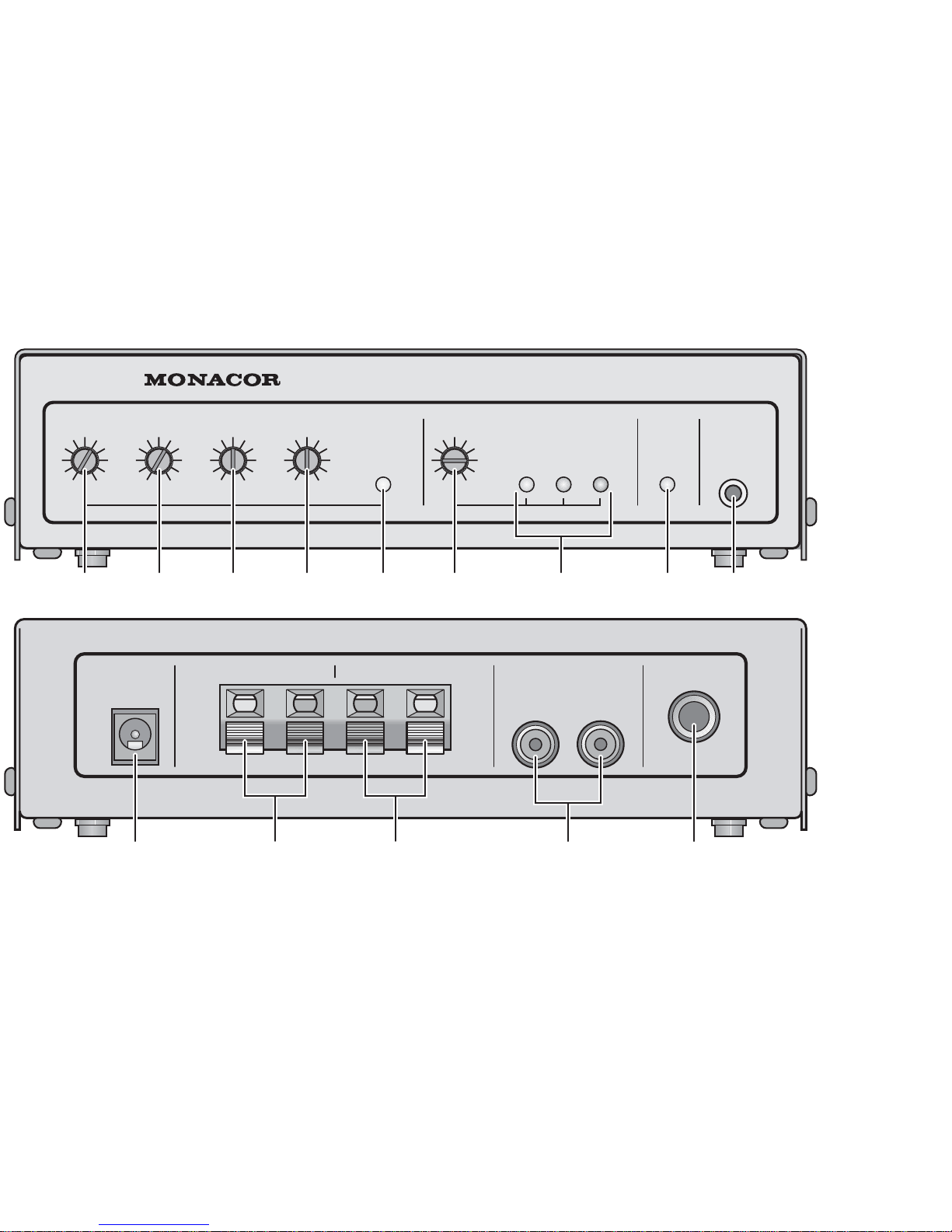
1 Übersicht der Bedienelemente und Anschlüsse
1.1 Frontseite
1 Lautstärkeregler für das Mikrofon
2 Lautstärkeregler für die Tonquelle am Line-Eingang
(13), z.B. Fernsehgerät
3 Klangregler BASS für die Tiefen
4 Klangregler TREBLE für die Höhen
5 Anzeige SIGNAL/PEAK; leuchtet grün, wenn ein Ein-
gangssignal vom Mikrofon oder der Tonquelle am LineEingang (13) vorhanden ist; leuchtet sie rot, ist der Eingang übersteuert: in diesem Fall den zugehörigen
Regler MIC (1) oder LINE (2) etwas zurückdrehen
6 Regler zur Einstellung des Schleifenstroms
(siehe Kap. 4.7)
7 Anzeige für den Schleifenstrom
8 Betriebsanzeige
9 Anschluss für einen Kopfhörer
1.2 Rückseite
10 Kleinspannungsbuchse 12V~/1,5 Azum Anschluss des
mitgelieferten Steckernetzgeräts
11 Anschlussklemmen für die Induktionsschleife
12 Anschlussklemmen für einen Schalter oder Taster zum
Auslösen eines Signaltons
13 Line-Eingang zum Anschluss einer Tonquelle mit Line-
Pegel (z.B. Fernsehgerät, CD-Spieler, Kassettenrekorder)
14 Mikrofoneingang, asymmetrisch beschaltete 6,3-mm-
Klinkenbuchse mit einer Versorgungsspannung für
Elektret-Kondensatormikrofone am Spitzenkontakt
4
CH
A
D
Page 5
2 Hinweise für den sicheren Gebrauch
Die Geräte (Verstärker und Netzgerät) entsprechen allen
erforderlichen Richtlinien der EU und sind deshalb mit
gekennzeichnet.
Beachten Sie auch unbedingt folgende Punkte:
●
Setzen Sie den Verstärker und das Netzgerät nur im Innenbereich ein und schützen Sie die Geräte vor Tropf- und
Spritzwasser, hoher Luftfeuchtigkeit und Hitze (zulässiger
Einsatztemperaturbereich 0–40 °C).
●
Nehmen Sie den Verstärker nicht in Betrieb oder ziehen
Sie das Netzgerät sofort aus der Steckdose:
1. wenn sichtbare Schäden an dem Verstärker oder am
Netzgerät vorhanden sind,
2. wenn nach einem Sturz oder Ähnlichem der Verdacht
auf einen Defekt besteht,
3. wenn Funktionsstörungen auftreten.
Lassen Sie den Verstärker oder das Netzgerät in jedem
Fall in einer Fachwerkstatt reparieren.
●
Verwenden Sie für die Reinigung nur ein trockenes, weiches Tuch, niemals Chemikalien oder Wasser.
●
Wird der Verstärker oder das Netzgerät zweckentfremdet, falsch angeschlossen, nicht richtig bedient oder
nicht fachgerecht repariert, kann keine Haftung für daraus resultierende Sach- oder Personenschäden und
keine Garantie für die Geräte übernommen werden.
3 Einsatzmöglichkeiten
Der LA-40 ist für den Aufbau einer induktiven Höranlage im
Heimbereich bestimmt. Er überträgt mithilfe einer Kabelschleife Tonsignale (z.B. von einem Fernsehgerät) zu Hörgeräten mit einer „Telefonspule“ und zu induktiven Empfängern (z.B. LR-200 von MONACOR). Durch die
drahtlose Signalübertragung kann sich der Benutzer innerhalb der Schleife frei bewegen.
Der LA-40 ist mit einem Dynamikkompressor ausgestat-
tet und eignet sich für Flächen von max. 40m
2
.An ihn können eine Tonquelle mit Line-Pegel (z.B. Fernsehgerät, CDSpieler) und ein Mikrofon angeschlossen und deren
Sollen die Geräte endgültig aus dem Betrieb
genommen werden, übergeben Sie sie zur umweltgerechten Entsorgung einem örtlichen Recyclingbetrieb.
WARNUNG Das Netzgerät wird mit lebensgefährlich
hoher Netzspannung versorgt. Nehmen
Sie deshalb niemals selbst Eingriffe am
Gerät vor. Durch unsachgemäßes Vorgehen besteht die Gefahr eines elektrischen
Schlages.
5
CH
A
D
Page 6

Lautstärken getrennt eingestellt werden. Das Mikrofon
überträgt zusätzlich die Umgebungsgeräusche und im
Raum gesprochene Worte. Das ist sinnvoll, wenn der Empfänger kein eigenes Mikrofon hat oder das Hörgerät nicht
die Möglichkeit bietet, sein Mikrofon und die Telefonspule
gemeinsam zu nutzen (Modus „MT“). Über einen Schalteingang kann ein Signalton ausgelöst werden. Ein Anschlusskabel mit einem bei Fernsehgeräten üblichen SCARTStecker und ein 35m langes Kabel zum Aufbau der
Induktionsschleife werden mitgeliefert.
3.1 Funktionsprinzip
Ein Kabel wird als Induktionsschleife am Fußboden, in der
Wand oder an der Decke verlegt. Innerhalb dieser Schleife
baut sich entsprechend der Tonquelle ein Magnetfeld auf,
das mit der „T elefonspule“ des Hörgeräts oder einem anderen Induktivempfänger empfangen und wieder in Töne
zurückgewandelt wird. Innerhalb einer Induktionsschleife
lassen sich beliebig viele Empfänger betreiben.
4 Installation und Inbetriebnahme
4.1 Verstärker aufstellen
Vor dem Aufstellen des Verstärkers die vier selbstklebenden Gummifüße unter das Gerät kleben (wie in den
Abbildungen 1 und 2 zu sehen). Ist der Betrieb mit einem
Mikrofon vorgesehen, sollte der Verstärker wegen erhöhter
Rückkopplungsgefahr außerhalb der Schleife aufgestellt
werden.
4.2 Induktionsschleife
Mit dem LA-40 kann eine induktive Höranlage für eine Fläche von bis zu 40m
2
realisiert werden. Als Schleife wird
das beiliegende Kabel mit einer einzelnen Windung am
Rand der Hörfläche verlegt. Der Abstand zur Ohrhöhe bzw.
des Empfängers sollte ca. 1 – 2 m betragen. Eine Verlegung in unterschiedlichen Höhen sollte vermieden werden.
Magnetische Felder (z.B. durch T ransformatoren, Starkstromleitungen oder Leuchtstofflampen) und Metallteile in
Fußböden, Decken und Wänden können den Betrieb der
Induktionsschleife beeinträchtigen. Deshalb vor der endgültigen Verlegung des Kabels zur Bestimmung der optimalen Schleifenposition einen Probebetrieb durchführen.
Bei der Verlegung der Induktionsschleife in Rohren müssen diese aus Kunststoff sein, da Metallrohre das magnetische Feld der Schleife beeinflussen.
VORSICHT
Alle Anschlüsse sollten nur durch eine qualifizierte Fachkraft und unbedingt bei ausgeschaltetem Verstärker vorgenommen werden.
6
CH
A
D
Page 7

7
CH
A
D
Das Schleifenkabel kürzen, wenn es nicht in voller
Länge benötigt wird, jedoch nicht kürzer als 19 m, sonst
würde die minimale Lastimpedanz unterschritten, was zur
Überlastung des Verstärkers führen kann.
Zum Anschluss des Schleifenkabels den Kabelabschnitt
zwischen dem Verstärker und der Schleife, wenn möglich,
verdrillen und die beiden abisolierten Kabelenden an die
Klemmen SCHLEIFE (11) anschließen. Dabei auf guten
Kontakt achten, damit keine störenden Übergangswiderstände entstehen. Bei der Verlegung des Kabels einen
Kontakt zur Erdung bei beschädigter Isolierung vermeiden.
4.3 Mikrofone
Ein Mikrofon zur Übertragung der Umgebungsgeräusche
und im Raum gesprochener Worte an die 6,3-mm-Klinkenbuchse MIC (14) anschließen. Es wird ein Elektret-Kondensatormikrofon (z.B. das speziell für diesen Einsatz konzipierte ECM-300LA von MONACOR) empfohlen. Dieses
kann z.B. auf einen Tisch gelegt werden, von wo es am
besten die Umgebungsgeräusche wie auch das Klingeln
des Telefons aufnimmt. Die von diesem Mikrofon benötigte
Spannungsversorgung wird über den Spitzenkontakt der
Anschlussbuchse zur Verfügung gestellt (7,2V über
2kΩ).
Dynamische Mikrofone sind aufgrund der Rückkopplungsgefahr durch ihr elektromagnetisches Funktionsprinzip nicht geeignet.
4.4 Geräte mit Line-Pegel
Eine Tonquelle mit Line-Ausgang (z.B. Fernsehgerät, CDSpieler, Kassettenrekorder) an die Cinch-Buchsen LINE IN
(13) anschließen. Für den Anschluss eines Fernsehgerätes
kann das beiliegende Kabel verwendet werden.
4.5 Signalton
Ein im Gerät erzeugter Signalton kann über einen an den
Klemmen ALARM (12) angeschlossenen Schalter oder
Taster (z.B. in Form eines Klingelknopfes) ausgelöst werden. Solange die Kontakte verbunden sind, ist der Ton zu
hören.
4.6 Stromversorgung
Zum Schluss den Kleinspannungsstecker des Netzgeräts
in die Buchse 12V~/ 1,5 A (10) und das Netzgerät in eine
Netzsteckdose stecken. Mit dem Anschluss des Netzgerätes ist der Verstärker eingeschaltet; die Betriebsanzeige
ON (8) leuchtet. Zum bequemen Ein- und Ausschalten des
Geräts empfiehlt sich die Verwendung einer schaltbaren
Netzsteckdose oder einer Master-Slave-Steckdosenleiste
Page 8

(z.B. MCMS-144 von MONACOR), mit der es möglich ist,
den LA-40 automatisch mit dem Fernsehgerät zu schalten.
4.7 Inbetriebnahme
Gegen versehentliches Verstellen sind alle Regler versenkt
ausgeführt und können mit dem beiliegenden kleinen
Schraubendreher eingestellt werden.
1) Die Regler MIC (1) und LINE (2) und SCHLEIFENSTROM (6) zunächst auf Linksanschlag (MIN) drehen.
Die Klangregler BASS (3) und TREBLE (4) in die Mittelposition drehen.
2) Die Tonquelle (z. B. Fernsehgerät) einschalten. Den
Regler LINE (2) so weit aufdrehen, dass die Eingangspegel-LED (5) bei lauten Passagen grün leuchtet.
Leuchtet sie rot, den Regler wieder etwas zurückdrehen,
da der Ton sonst verzerrt wird.
3) Den Regler (6) für den Schleifenstrom so weit aufdrehen,
dass die 100%-LED der Anzeige SCHLEIFENSTROM
(7) bei lauten Passagen aufblinkt. Leuchtet sie permanent, ist der Strom zu hoch eingestellt und der Ton kann
verzerrt sein; den Regler entsprechend zurückdrehen.
Leuchtet keine der drei LEDs, die Schleife auf Unterbrechung prüfen.
4) Mit einem Hörgerät mit „Telefonspule“ (Modus oder
Schalterposition „T“) oder einem Induktivempfänger
(z.B. LR-200 von MONACOR) die Empfangsqualität
und den Klang innerhalb der Kabelschleife überprüfen.
5) Den optimalen Klang mit den Reglern BASS (3) für die
Tiefen und TREBLE (4) für die Höhen einstellen.
6) Falls ein Mikrofon an der Buchse MIC (14) angeschlossen ist, seinen Ton mit dem Regler MIC (1) hinzumischen. Den Regler nur so weit aufdrehen, dass die
Eingangspegel-LED (5) bei lauten Umgebungsgeräuschen nicht rot aufleuchtet.
4.8 Kopfhörer
An die 3,5-mm-Klinkenbuchse KOPFHÖRER (9) kann zur
Kontrolle des gesendeten Tons ein Kopfhörer angeschlossen werden. Die Kopfhörerlautstärke ist vom eingestellten
Schleifenstrom abhängig.
5 Bedienung
1) Die Tonquelle (z. B. Fernsehgerät) einschalten.
2) Die Stromversorgung für den V erstärker einschalten: Je
nach Art des Anschlusses
– das Steckernetzgerät in die Netzsteckdose stecken
oder
– den Schalter für die Steckdose einschalten
oder
8
CH
A
D
Page 9

– das Gerät ist bereits (automatisch) eingeschaltet.
Die Betriebsanzeige ON (8) leuchtet.
3) Den Induktivempfänger oder das Hörgerät mit „Telefonspule“ (Modus oder Schalterposition „T“ oder „MT“) einschalten und die gewünschte Lautstärke einstellen.
Nach dem Gebrauch zum Ausschalten in umgekehrter Reihenfolge vorgehen.
5.1 Lautstärkeverhältnis korrigieren
Nur bei angeschlossenem Mikrofon: Sind die Umgebungsgeräusche wie z.B. das im Raum gesprochene Wort
gegenüber der Tonquelle (z.B. Fernsehgerät) zu leise oder
zu laut, mit dem beiliegenden Schraubendreher die Mikrofonlautstärke am Regler MIC (1) korrigieren.
5.2 Klang ändern
Zur Korrektur des Klanges mit dem beiliegenden Schraubendreher die Tiefen mit dem Regler BASS (3) und die
Höhen mit dem Regler TREBLE (4) optimal einstellen.
5.3 Signalton auslösen
Durch Drücken eines an den Verstärker angeschlossenen
Tasters (z.B. Klingelknopfs) den Signalton auslösen.
6Technische Daten
Max. Schleifenstrom: . . . . . 2,8 A
Zulässiger Schleifen-
widerstand: . . . . . . . . . . . . . 0,4 –2Ω
Maximale Hörfläche: . . . . . . 40m
2
Eingänge (Empfindlichkeit/Impedanz, Anschluss)
MIC: . . . . . . . . . . . . . . . . 2mV/750 Ω,
6,3-mm-Klinke, asym.
Mikrofon-Versorgung: . . . 7,2 V über 2 kΩ (Spitzen-
kontakt)
LINE: . . . . . . . . . . . . . . . 200 mV/11 kΩ,
Cinch, links/rechts
Klangregelung
Tiefen: . . . . . . . . . . . . . . 100 Hz, ±8dB
Höhen: . . . . . . . . . . . . . . 10kHz,±10 dB
Frequenzbereich: . . . . . . . . 75Hz–7500Hz, ±3dB
Stromversorgung: . . . . . . . . 12V~/1,5A
über beiliegendes Netzgerät
230V~/50 Hz/22VA
Einsatztemperatur: . . . . . . . 0 –40 °C
Abmessungen (B× H ×T): . 175 × 45 × 102 mm
Gewicht: . . . . . . . . . . . . . . . 510g
Änderungen vorbehalten.
9
CH
A
D
Diese Bedienungsanleitung ist urheberrechtlich für MONACOR®INTERNA TIONALGmbH & Co. KG geschützt. Eine Reproduktion für
eigene kommerzielle Zwecke – auch auszugsweise – ist untersagt.
Page 10

Please unfold page 3. Then you can always see the
operating elements and connections described.
Contents
1 Operating Elements and Connections . . . . . . . . . 10
2 Safety Notes . . . . . . . . . . . . . . . . . . . . . . . . . . . . . 11
3 Applications . . . . . . . . . . . . . . . . . . . . . . . . . . . . . . 11
4 Installation and Setting into Operation . . . . . . . . . 12
5 Operation . . . . . . . . . . . . . . . . . . . . . . . . . . . . . . . 14
6 Specifications . . . . . . . . . . . . . . . . . . . . . . . . . . . . 15
1 Operating Elements and Connections
1.1 Front panel
1 Volume control for the microphone
2 Volume control for the audio source at the line input
(13), e.g. TV set
3 Tone control BASS for the bass range
4 Tone control TREBLE for the high range
5 Indicator SIGNAL/PEAK; shows green if an input signal
from the microphone or the audio source is available at
the line input (13); if it shows red, the input is overloaded: in this case slightly turn back the corresponding
control MIC (1) or LINE (2)
6 Control for adjusting the loop current (see chapter 4.7)
7 Indicator for the loop current
8 Power indicator
9 Headphone connection
1.2 Rear panel
10 Low-voltage jack 12V~/1.5 A for connection of the sup-
plied plug-in power supply unit
11 Terminals for the induction loop
12 Terminals for a switch or momentary pushbutton for
releasing a signal sound
13 Line input for connection of an audio source with line
level (e.g. TV set, CD player, cassette recorder)
14 Microphone input, unbalanced 6.3mm jack with a sup-
ply voltage for electret condenser microphones at the tip
contact
10
GB
Page 11
2 Safety Notes
The units (amplifier and power supply unit) correspond to
all required directives of the EU and are therefore marked
with .
It is essential to observe the following items:
●
The amplifier and the power supply unit are suitable for
indoor use only . Protect them against dripping water and
splash water, high air humidity, and heat (admissible
ambient temperature range 0– 40 °C).
●
Do not set the amplifier into operation, or immediately
disconnect the power supply unit from the mains socket
if:
1. there is visible damage to the amplifier or the power
supply unit,
2. a defect might have occurred after a drop or similar
accident,
3. malfunctions occur.
The amplifier or the power supply unit must in any case
be repaired by skilled personnel.
●
For cleaning only use a dry, soft cloth, by no means
chemicals or water.
●
No guarantee claims for the amplifier or the power supply unit and no liability for any resulting personal damage
or material damage will be accepted if the units are used
for other purposes than originally intended, if they are not
correctly connected, operated, or not repaired in an
expert way.
3 Applications
The LA-40 is designed for setting up an inductive sound
reproduction system for home applications. By means of a
cable loop it transmits audio signals (e.g. from a TV set) to
hearing aids with a “telephone coil” and to inductive receivers (e. g. LR-200 from MONACOR). Due to the wireless
signal transmission the user can move freely within the loop.
The LA-40 is equipped with a dynamic compressor and
is suitable for areas of 40m
2
as a maximum. It allows to
connect an audio source with line level (e.g. TV set, CD
player) and a microphone and to adjust their volumes sepa-
If the units are to be put out of operation definitively, take them to a local recycling plant for a
disposal which is not harmful to the environment.
WARNING
The power supply unit is supplied with hazardous mains voltage. Leave servicing to
skilled personnel only . Inexpert handling may
cause an electric shock hazard.
11
GB
Page 12

rately. The microphone additionally transmits the ambient
noise and words spoken in the room. This is useful if the
receiver does not have an individual microphone or if the
hearing aid does not allow to use its microphone and the
telephone coil together (mode “MT”). Via a control input a
signal sound can be triggered. A connection cable with a
standard SCART plug for TV sets and a cable of 35 m
length for setting up the induction loop are supplied together with the unit.
3.1 Operational principle
Acable is laid as an induction loop into the floor, the wall, or
into the ceiling. Within this loop, according to the audio
source, a magnetic field is created which is received with
the “telephone coil” of the hearing aid or another inductive
receiver and is reconverted into sound. It is possible to operate within an induction loop as many receivers as desired.
4 Installation and Setting into Operation
4.1 Setting up the amplifier
Prior to setting up the amplifier glue the four self-adhesive
rubber feet under the unit (as shown in figs. 1 and 2). For
operation with a microphone, the amplifier should be set up
outside the loop because of the increased susceptibility to
acoustic feedback.
4.2 Induction loop
The LA-400 allows to realize an inductive sound reproduction system for an area of up to 40m
2
. As a loop, the supplied cable is laid with a single winding at the edge of the
hearing area. The distance to ear level or to the receiver
should be approx. 1 to 2m. It should be avoided to lay the
loop at different heights.
Magnetic fields (e.g. caused by transformers, high
power cables, or fluorescent lamps) and metal parts in
floors, ceilings, and walls may impair the operation of the
induction loop. Therefore, prior to laying the cable definitively, make a trial run to determine the optimum loop position. When laying the induction loop in tubes, these must be
made of plastic as metal tubes will affect the magnetic field
of the loop.
Shorten the loop cable if it is not required in its full length,
however, not shorter than 19m, otherwise this value would
CAUTION
All connections should only be made by qualified personnel and in any case with the amplifier switched off.
12
GB
Page 13

fall below the minimum load impedance which may lead to
overload of the amplifier.
For connection of the loop cable, twist the cable section
between the amplifier and the loop, if possible, and connect
the two stripped cable ends to the terminals LOOP (11).
Pay attention to a good contact so that no interfering contact resistance will result. When laying the cable, avoid any
connection to earthing if the insulation is damaged.
4.3 Microphones
Connect a microphone for transmission of the ambient
noise and words spoken in the room to the 6.3mm jack
MIC (14). An electret condenser microphone (e. g. ECM300LA from MONACOR especially designed for this application) is recommended. This may e. g. be placed on a
table from where it picks up ambient noise and telephone
ringing best. The supply voltage required by this microphone is made available via the tip contact of the connection jack (7.2V via 2 kΩ).
Dynamic microphones are not suitable because of the
susceptibility to feedback due to their electromagnetic operational system.
4.4 Units with line level
Connect an audio source with line output (e.g. TV set, CD
player, cassette recorder) to the phono jacks LINE IN (13).
For connection of a TV set, the supplied cable may be
used.
4.5 Signal sound
A signal sound created in the unit may be released via a
switch or momentary pushbutton (e.g. in the form of a bell
knob) connected to the terminals ALERT (12). As long as
the contacts are connected, the sound can be heard.
4.6 Power supply
Finally connect the low voltage plug of the power supply unit
to the jack 12V~/ 1.5 A (10) and the power supply unit to a
mains socket. With the connection of the power supply unit
the amplifier is switched on; the power indicator ON (8) lights
up. To switch the unit on and off conveniently, it is recommended to use a switchable mains socket or a master-slave
socket rail (e.g. MCMS-144 from MONACOR) which allows
to switch the LA-40 automatically with the TV set.
13
GB
Page 14

4.7 Setting into Operation
All controls are of recessed design to prevent accidental
misadjustment and can be adjusted with the supplied small
screwdriver.
1) For the time being, turn the controls MIC (1) and LINE
(2) and LOOP CURRENT (6) to the left stop (MIN). Turn
the tone controls BASS (3) and TREBLE (4) to mid-position.
2) Switch on the audio source (e.g. TV set). Turn up the
control LINE (2) so that the input level indicator (5)
shows green with passages of high volume. If it shows
red, slightly turn back the control as otherwise the sound
will be distorted.
3) Turn up the control (6) for the loop current so that the
100% LED of the indicator LOOP CURRENT (7) flashes
with passages of high volume. If it lights up permanently ,
the current has been adjusted too high and the sound
may be distorted; turn back the control correspondingly.
If none of the three LEDs light up, check the loop for
interruption.
4) With a hearing aid with “telephone coil” (mode or switch
position “T”) or an inductive receiver (e.g. LR-200 from
MONACOR), check the reception quality and the sound
within the cable loop.
5) Adjust the optimum sound with the controls BASS (3) for
the bass range and TREBLE (4) for the high range.
6) If a microphone is connected to the jack MIC (14), add
its sound with the control MIC (1). Only turn up the control so that the input level indicator (5) does not show red
with ambient noise of high volume.
4.8 Headphones
Headphones may be connected to the 3.5mm jack
PHONES (9) to check the transmitted sound. The headphone volume depends on the adjusted loop current.
5 Operation
1) Switch on the audio source (e.g. TV set).
2) Switch on the power supply for the amplifier: Depending
on the kind of the connection
– connect the plug-in power supply unit to the mains
socket
or
– switch on the switch for the socket
or
– the unit has already been switched on (automatically).
The power indicator ON (8) lights up.
14
GB
Page 15

3) Switch on the inductive receiver or the hearing aid with
“telephone coil” (mode or switch position “T” or “MT”)
and adjust the desired volume.
For switching off after use, proceed in reverse order.
5.1 Readjust the volume ratio
Only with a microphone connected: If the ambient noise
e. g. the word spoken in the room is too low or too high
compared to the audio source (e.g. TV set), readjust the
microphone volume at the control MIC (1) with the supplied
screwdriver.
5.2 Changing the sound
To readjust the sound, adjust the bass range with the control BASS (3) and the high range with the control TREBLE
(4) in an optimum way with the supplied screwdriver.
5.3 Releasing the signal sound
Release the signal sound by pressing a momentary pushbutton (e.g. bell knob) connected to the amplifier.
6 Specifications
Max. loop current: . . . . . . . . 2.8A
Admissible loop resistance: 0.4– 2 Ω
Maximum hearing area: . . . 40m
2
Inputs (sensitivity/impedance, connection)
MIC: . . . . . . . . . . . . . . . . 2mV/750 Ω,
6.3mm jack, unbal.
microphone supply: . . . . 7.2V via 2kΩ
(tip contact)
LINE: . . . . . . . . . . . . . . . 200mV/11kΩ,
phono, left/right
Tone control
BASS: . . . . . . . . . . . . . . . 100 Hz, ±8dB
HIGH: . . . . . . . . . . . . . . . 10kHz, ±10 dB
Frequency range: . . . . . . . . 75 Hz– 7 500Hz, ±3 dB
Power supply: . . . . . . . . . . . 12V~/1.5A via supplied
power supply unit
230V~/50 Hz/22VA
Ambient temperature: . . . . . 0– 40°C
Dimensions (W × H × D): . . 175 × 45 × 102 mm
Weight: . . . . . . . . . . . . . . . . 510 g
Subject to technical modification.
15
GB
All rights reserved by MONACOR®INTERNATIONAL GmbH & Co. KG. No part of this instruction manual may be reproduced in any
form or by any means for any commercial use.
Page 16

Ouvrez le présent livret page 3 de manière à visualiser
les éléments et branchements.
Table des matières
1 Eléments et branchements . . . . . . . . . . . . . . . . . . 16
2 Conseils d’utilisation et de sécurité . . . . . . . . . . . . 17
3 Possibilités d’utilisation . . . . . . . . . . . . . . . . . . . . . 17
4 Installation et fonctionnement . . . . . . . . . . . . . . . . 18
5 Utilisation . . . . . . . . . . . . . . . . . . . . . . . . . . . . . . . . 20
6 Caractéristiques techniques . . . . . . . . . . . . . . . . . 21
1 Eléments et branchements
1.1 Face avant
1 Potentiomètre de réglage de volume pour le microphone
2 Potentiomètre de réglage de volume pour la source
audio à l’entrée ligne (13), par exemple téléviseur
3 Egaliseur BASS pour les graves
4 Egaliseur TREBLE pour les aigus
5 LED SIGNAL/PEAK : brille en vert si un signal d’entrée
du microphone ou de la source audio est présent à l’entrée ligne (13) ; si elle brille en rouge, l’entrée est en surcharge : dans ce cas, tournez le réglage correspondant
MIC (1) ou LINE (2) dans l’autre sens.
6 Potentiomètre de réglage pour le courant boucle (voir
chapitre 4.7)
7 Affichage pour le courant boucle
8 Témoin de fonctionnement
9 Branchement pour un casque
1.2 Face arrière
10 Prise basse tension 12V~/1,5 A pour relier le bloc
secteur livré
11 Bornes de branchement pour la boucle d’induction
12 Bornes de branchement pour un interrupteur ou un
bouton poussoir pour déclencher un signal sonore
13 Entrée ligne pour brancher une source audio avec
niveau ligne (par exemple téléviseur, lecteur CD, magnétophone)
14 Entrée micro, prise jack 6,35 femelle branchée en asy-
métrique avec tension d’alimentation pour microphones
électret à condensateurs au contact de la pointe
16
CH
B
F
Page 17

2 Conseils d’utilisation et de sécurité
Les appareils (amplificateur et bloc secteur) répondent à
toutes les directives nécessaires de l’Union Européenne et
portent donc le symbole .
Respectez scrupuleusement les points suivants :
●
L’amplificateur et le bloc secteur ne sont conçus que
pour une utilisation en intérieur. Protégez-les de tout type
de projections d’eau, des éclaboussures, d’une humidité
élevée d’air et de la chaleur (plage de température de
fonctionnement autorisée : 0– 40 ºC).
●
Ne faites jamais fonctionner l’amplificateur et débranchez immédiatement le bloc secteur lorsque :
1. des dommages visibles sur l’appareil ou le bloc secteur apparaissent,
2. après une chute ou accident similaire, l’appareil ou le
bloc secteur peut présenter un défaut.
3. des défaillances apparaissent.
Dans tous les cas, les dommages doivent être réparés
par un technicien spécialisé.
●
Pour nettoyer l’appareil, utilisez uniquement un chiffon sec
et doux, en aucun cas de produits chimiques ou d’eau.
●
Nous déclinons toute responsabilité en cas de dommages matériels ou corporels résultants si l’appareil ou le
bloc secteur est utilisé dans un but autre que celui pour
lequel il a été conçu, s’il n’est pas correctement branché,
utilisé ou réparé par une personne habilitée ; en outre, la
garantie deviendrait caduque.
3 Possibilités d’utilisation
Le LA-40 permet de créer un système de reproduction
audio inductif pour applications au domicile. Il transmet à
l’aide d’une boucle de câble, des signaux audio (p.ex. d’un
téléviseur) vers des appareils auditifs avec “bobine téléphone” et des récepteurs à induction (par exemple LR-200
de MONACOR). La transmission sans fil du signal permet
à l’utilisateur de se déplacer librement au sein de la boucle.
Le LA-40 est équipé d’un compresseur dynamique et est
adapté pour une superficie de 40m
2
maximum. On peut y
relier une source audio avec niveau ligne (p.ex. téléviseur,
Lorsque les appareils sont définitivement retirés
du service, vous devez les déposer dans une
usine de recyclage à proximité pour contribuer à
leur élimination non polluante.
AVERTISSEMENT Le bloc secteur est alimenté par une
tension élevée et dangereuse. Ne
touchez jamais l’intérieur de l’appareil car en cas de mauvaise manipulation, vous pourriez subir une décharge électrique.
17
CH
B
F
Page 18

lecteur CD) et un microphone et régler séparément leur
volume. Le microphone transmet en plus les bruits ambiants et les mots prononcés dans la pièce. Cela est intéressant lorsque le récepteur n’a pas de microphone propre
ou lorsque l’appareil auditif ne permet pas d’utiliser son
microphone et la bobine téléphone ensemble (mode “MT”).
Via une entrée de contrôle, un signal sonore peut être émis.
Un cordon de branchement avec une fiche PERITEL classique pour téléviseurs et un câble de 35m de long pour
créer la boucle d’induction sont livrés avec l’appareil.
3.1 Principe de fonctionnement
Un câble est placé, comme boucle d’induction, dans le sol,
mur ou plafond. Un champ magnétique se crée ainsi au
sein de la boucle en fonction de la source audio, ce champ
est reçu avec la “bobine téléphone” de l’appareil auditif ou
un autre récepteur à induction puis est reconverti en son.
On peut faire fonctionner autant de récepteurs que voulu
au sein d’une boucle d’induction.
4 Installation et fonctionnement
4.1 Positionnement de l’amplificateur
Avant de placer l’amplificateur, collez les quatre pieds
caoutchouc autocollants sous l’appareil (comme montré
sur les schémas 1 et 2). Si le fonctionnement avec un
microphone est prévu, l’amplificateur devrait être positionné en dehors de la boucle à cause de risques de larsen.
4.2 Boucle d’induction
Avec le LA-40, des installations audio inductives peuvent
être réalisées pour une surface jusqu’à 40 m
2
. Le câble
livré posé en un enroulement unique à la périphérie de la
surface d’écoute constitue la boucle. La distance avec le
niveau de l’oreille ou du récepteur devrait être de 1 à 2m
environ. Il faudrait éviter un emplacement à des hauteurs
diverses.
Des champs magnétiques (p. ex. par transformateurs,
lignes courants forts ou lampes fluorescentes) et des parties métalliques dans le sol, plafond ou mur, peuvent influer
sur le comportement de la boucle d’induction. C’est pourquoi avant de placer définitivement le câble, effectuez un
test de fonctionnement pour déterminer la position optimale de la boucle. Lors du positionnement de la boucle dans
les tubes, ces derniers doivent être en plastique puisque
les tubes métalliques influent sur le champ magnétique de
la boucle.
PRECAUTION
Seul un technicien habilité devrait effectuer les branchements et uniquement lorsque l’amplificateur est éteint.
18
CH
B
F
Page 19

Si toute la longueur du câble n’est pas nécessaire, réduisez-le mais pas à moins de 19 m sinon on passera sous
l’impédance minimale de charge ce qui peut mener à une
surcharge de l’amplificateur.
Pour brancher le câble de la boucle, torsadez la partie
de câble entre l’amplificateur et la boucle, si possible, et
reliez les deux extrémités dénudées du câble aux bornes
LOOP (11). Veillez à assurer un bon contact pour qu’aucune résistance de transmission perturbatrice ne survienne. Lors du positionnement du câble, évitez un contact à la
terre si l’isolation est endommagée.
4.3 Microphones
Reliez un microphone pour la transmission des bruits
ambiants et des mots exprimés dans la pièce à la fiche jack
6,35 MIC (14). Nous recommandons un microphone électret à condensateur (p.ex., le ECM-300LA de MONACOR
spécialement conçu pour cette utilisation). Il peut par exemple être posé sur une table là où il capte le mieux les bruits
ambiants et la sonnerie du téléphone. La tension d’alimentation nécessaire pour le microphone est disponible via le
contact pointe de la prise (7,2V au-dessus de 2 kΩ).
Les microphones dynamiques ne sont pas adaptés à
cause d’un risque de larsen via leur principe de fonctionnement électromagnétique.
4.4 Appareils à niveau ligne
Reliez une source audio avec sortie ligne (par exemple
téléviseur, lecteur CD, magnétophone) aux prises RCA
LINE IN (13). Pour le branchement d’un téléviseur, utilisez
le câble livré.
4.5 Signal sonore
Un signal produit dans l’appareil peut être déclenché via un
interrupteur ou bouton poussoir momentané (par exemple
sous forme d’un bouton sonnette) relié aux bornes ALERT
(12). Tant que les contacts sont reliés, le son est audible.
4.6 Alimentation
Mettez maintenant la fiche basse tension du bloc secteur à
la prise 12V~/1,5 A(10) et reliez le bloc secteur à une prise
secteur. L’appareil est allumé avec le branchement du bloc
secteur ; le témoin de fonctionnement ON (8) brille. Pour
allumer et éteindre confortablement l’appareil, nous vous
recommandons d’utiliser une prise secteur commutable ou
une barrette master/slave (par exemple MCMS-144 de
MONACOR) qui permet de commuter directement le LA-40
avec le téléviseur.
19
CH
B
F
Page 20

4.7 Fonctionnement
Tous les réglages sont encastrés pour éviter tout déréglage accidentel et peuvent être réglés avec le petit tournevis
livré.
1) Tournez les réglages MIC (1) et LINE (2) et LOOP CURRENT (6) tout d’abord sur la butée de gauche (MIN).
Tournez les égaliseurs BASS (3) et TREBLE (4) sur la
position médiane.
2) Allumez la source audio (par exemple téléviseur). Tournez le réglage LINE (2) jusqu’à ce que la LED du niveau
d’entrée (5) brille en vert pour des passages élevés. Si
elle brille en rouge, tournez le réglage dans l’autre sens
pour diminuer sinon le son est distordu.
3) Tournez le réglage (6) pour le courant boucle jusqu’à ce
que la LED 100% de l’affichage LOOP CURRENT (7)
clignote pour des passages élevés. Si elle brille en permanence, le réglage du courant est trop élevé et le son
peut être distordu ; tournez le réglage dans l’autre sens.
Si aucune des trois LEDs ne brille, vérifiez s’il n’y a pas
de rupture de la boucle.
4) Vérifiez la qualité de réception et la tonalité au sein de la
boucle du câble avec un appareil auditif avec “bobine
téléphone” (mode ou position interrupteur “T”) ou avec
un récepteur à induction (par exemple LR-200 de
MONACOR).
5) Réglez la tonalité optimale avec les réglages BASS (3)
pour les graves et TREBLE (4) pour les aigus.
6) Si un microphone est relié à la prise MIC (14), mixez son
son avec le réglage MIC (1). Tournez le réglage tant que
la LED de niveau d’entrée (5) ne brille pas en rouge pour
des bruits ambiants élevés.
4.8 Casque
On peut relier un casque à la prise jack 3,5 PHONES (9)
pour contrôler le son émis ; le volume du casque dépend du
courant boucle réglé.
5 Utilisation
1) Allumez la source audio (par exemple téléviseur).
2) Allumez l’alimentation pour l’amplificateur ; selon le type
de branchement :
– reliez le bloc secteur à une prise secteur
ou
– allumez l’interrupteur de la barrette
ou
– l’appareil a déjà été allumé (automatiquement)
Le témoin de fonctionnement ON (8) brille.
20
CH
B
F
Page 21

3) Allumez le récepteur à induction ou l’appareil auditif
avec “bobine téléphone” (mode ou position interrupteur
“T” ou “MT”) et réglez le volume souhaité.
Après utilisation, procédez dans l’ordre inverse pour éteindre.
5.1 Correction du rapport de volume
Uniquement si un microphone est relié : si les bruits ambiants par exemple les mots prononcés dans une pièce
sont trop faibles ou trop forts par rapport à la source audio
(par exemple téléviseur), corrigez le volume du microphone
avec le petit tournevis livré sur le réglage MIC (1).
5.2 Modification de la tonalité
Pour corriger la tonalité, réglez les graves avec le réglage
BASS (3) et les aigus avec le réglage TREBLE (4) de manière optimale en vous aidant du tournevis livré.
5.3 Déclenchement du signal sonore
En appuyant sur un bouton poussoir relié à l’amplificateur
(par exemple bouton de sonnette), déclenchez le signal
sonore.
6 Caractéristiques techniques
Courant boucle max. : . . . . . . 2,8 A
Résistance boucle autorisée : 0,4 – 2 Ω
Superficie maximale d’écoute : 40 m
2
Entrées (sensibilité/impédance, branchement)
MIC : . . . . . . . . . . . . . . . . . 2 mV/750Ω,
jack 6,35, asym.
Alimentation micro : . . . . . 7,2V via 2 kΩ
(contact à la pointe)
LINE : . . . . . . . . . . . . . . . . 200 mV/11 kΩ,
RCA, gauche/droite
Egaliseur
Graves : . . . . . . . . . . . . . . 100Hz, ± 8 dB
Aigus : . . . . . . . . . . . . . . . . 10kHz, ±10 dB
Bande passante : . . . . . . . . . 75 Hz – 7500 Hz, ±3dB
Alimentation : . . . . . . . . . . . . 12 V~/1,5A
via bloc secteur livré
230V~/50 Hz/22VA
Température fonc. : . . . . . . . . 0– 40 ºC
Dimensions (L × H × P) : . . . . 175 × 45 × 102 mm
Poids : . . . . . . . . . . . . . . . . . . 510g
Tout droit de modification réservé.
21
CH
B
F
Notice d’utilisation protégée par le copyright de MONACOR®INTERNATIONAL GmbH & Co. KG. Toute reproduction même partielle
à des fins commerciales est interdite.
Page 22

Vi preghiamo di aprire completamente la pagina 3. Così
vedrete sempre gli elementi di comando e i collegamenti descritti.
Indice
1 Elementi di comando e collegamenti . . . . . . . . . . 22
2Avvertenze di sicurezza . . . . . . . . . . . . . . . . . . . . 23
3 Possibilità d’impiego . . . . . . . . . . . . . . . . . . . . . . . 23
4 Installazione e messa in funzione . . . . . . . . . . . . . 24
5 Funzionamento . . . . . . . . . . . . . . . . . . . . . . . . . . . 26
6 Dati tecnici . . . . . . . . . . . . . . . . . . . . . . . . . . . . . . . 27
1 Elementi di comando e collegamenti
1.1 Lato frontale
1 Regolatore volume per il microfono
2 Regolatore volume per la sorgente audio all’ingresso di
linea (13), p.es. televisore
3 Regolatore toni BASS per le frequenze basse
4 Regolatore toni TREBLE per le frequenze alte
5 Spia SIGNAL/PEAK; si accende di color verde se è pre-
sente un segnale d’ingresso proveniente dal microfono
o dalla sorgente all’ingresso di linea (13); se si accende
di rosso, l’ingresso è sovrapilotato: in questo caso ridurre leggermente il relativo regolatore MIC (1) o LINE (2)
6 Regolatore per impostare la corrente del loop
(vedi cap. 4.7)
7 Spie per la corrente del loop
8 Spia di funzionamento
9 Contatto per una cuffia
1.2 Lato posteriore
10 Presa DC per l’alimentazione 12V~/1,5 Aper il collega-
mento dell’alimentatore in dotazione
11 Morsetti per il loop ad induzione
12 Morsetti per un interruttore o pulsante per far scattare
un segnale acustico
13 Ingresso di linea per il collegamento di una sorgente
audio con livello di linea (p.es. televisore, lettore CD,
registratore a cassette)
14 Ingresso microfono, presa jack 6,3mm asimmetrica con
tensione d’alimentazione per un microfono elettrete a
condensatore al contatto in punta
22
I
Page 23

2Avvertenza di sicurezza
Gli apparecchi (amplificatore e alimentatore) sono conformi a tutte le direttive richieste dell’UE e pertanto portano la
sigla .
Si devono osservare assolutamente anche i seguenti punti:
●
Far funzionare l’amplificatore e l’alimentatore solo all’interno di locali e proteggerli dall’acqua gocciolante e dagli
spruzzi d’acqua, da alta umidità dell’aria e dal calore
(temperatura d’impiego ammessa fra 0 e 40°C).
●
Non mettere in funzione l’amplificatore o staccare subito
l’alimentatore dalla rete se:
1. l’amplificatore o l’alimentatore presentano dei danni
visibili;
2. dopo una caduta o dopo eventi simili sussiste il
sospetto di un difetto;
3. l’apparecchio non funziona correttamente.
Per la riparazione dell’amplificatore o dell’alimentatore
rivolgersi sempre ad un’officina competente.
●
Per la pulizia usare solo un panno morbido, asciutto; non
impiegare in nessun caso prodotti chimici o acqua.
●
Nel caso d’uso improprio, di collegamenti o impieghi sbagliati o di riparazione non a regola d’arte dell’amplificatore o dell’alimentatore, non si assume nessuna responsabilità per eventuali danni consequenziali a persone o a
cose e non si assume nessuna garanzia per gli apparecchi.
3Possibilità d’impiego
Il LA-40 è previsto per la creazione di un impianto ad induzione di ascolto in ambiente casalingo. Con l’aiuto di un
loop si trasmettono segnali audio (p.es. da un televisore)
ad apparecchi acustici con “bobina telefonica” e a ricevitori ad induzione (p. es. LR-200 della MONACOR). Grazie
alla trasmissione wireless dei segnali, l’utente si può muovere liberamente all’interno del loop.
Il LA-40 dispone di un processore dinamico ed è adatto
per superfici fino a 40 m
2
max. Si possono collegare una
sorgente audio con livello di linea (p.es. televisore, lettore
Se si desidera eliminare gli apparecchi definitivamente, consegnarli per lo smaltimento ad un’istituzione locale per il riciclaggio.
AVVERTIMENTO L’alimentatore funziona con pericolosa
tensione di rete. Non intervenire mai
personalmente al suo interno! La
manipolazione scorretta può provocare una scarica elettrica pericolosa.
23
I
Page 24

CD) e un microfono i cui volumi si possono regolare separatamente. Il microfono trasmette in più i rumori ambientali e
le parole pronunciate nella stanza. Questo fatto è pratico se
il ricevitore non dispone di un suo microfono oppure se l’apparecchio acustico non presenta la possibilità di sfruttare
insieme il microfono e la bobina telefonica (modalità “MT”).
Tramite un ingresso di comando è possibile far scattare un
segnale acustico. Sono in dotazione un cavo di collegamento con connettore SCART per il televisore e un cavo di
35 metri di lunghezza per creare il loop ad induzione.
3.1 Principio di funzionamento
Il cavo viene sistemato come loop ad induzione nella parete o nel soffitto. All’interno del loop si crea un campo magnetico che viene ricevuto e ritrasformato in segnale audio
per mezzo della “bobina telefonica” dell’apparecchio acustico o di un altro ricevitore ad induzione. All’interno di un loop
ad induzione si può gestire un numero illimitato di ricevitori.
4 Installazione e messa in funzione
4.1 Collocare l’amplificatore
Prima di collocare l’amplificatore, incollare i quattro piedini
autoadesivi sotto l’apparecchio (come si vede nelle figure 1
e 2). Se è previsto il funzionamento con un microfono,
l’amplificatore dovrebbe essere sistemato al di fuori del
loop per via del pericolo di feedback acustico.
4.2 Loop ad induzione
Con il LA-40 è possibile realizzare un impianto acustico ad
induzione per una superficie fino a 40m
2
. Come loop, si utilizza il cavo in dotazione con singola spira ai bordi della
zona. La distanza dall’altezza dell’orecchio o del ricevitore
dovrebbe essere di 1– 2 m ca. È sconsigliabile la sistemazione ad altezze differenti.
I campi magnetici (p.es. da trasformatori, linee di corrente forte o lampade al neon) e le parti metallici in pavimenti, soffitti e pareti possono compromettere il funzionamento del loop ad induzione. Perciò conviene fare una
prova prima della sistemazione definitiva del cavo per
determinare la posizione ottimale del loop. In caso di sistemazione del loop ad induzione in tubi, i tubi devono essere
di plastica in quanto i tubi metallici interferiscono nel campo
magnetico del loop.
Accorciare il cavo del loop se non è richiesta tutta la sua
lunghezza, ma non portarlo a meno di 19m, altrimenti si
ATTENZIONE
Tutti i collegamenti dovrebbero essere eseguiti solo da
una persona esperta e qualificata e assolutamente con
l’amplificatore spento.
24
I
Page 25

rimarrebbe sotto l’impedenza minima di carico il ché può
avere come conseguenza il sovraccarico dell’amplificatore.
Per il collegamento del cavo del loop, twistare, se possibile, la parte fra amplificatore e loop, e collegare i due terminali deisolati con i morsetti LOOP (11). Controllare un
buon contatto per escludere resistenze di contatto che
potrebbero disturbare. Posando il cavo, evitare un contatto con la massa in caso di isolamento danneggiato.
4.3 Microfoni
Per la trasmissione dei rumori ambientali e delle parole
pronunciate nella stanza, collegare un microfono con la
presa jack 6,3mm MIC (14). Si consiglia l’uso di un microfono elettrete a condensatore (p.es. l’ ECM-300LA di
MONACOR realizzato espressamente per questo impiego). Il microfono può essere messo, per esempio, su un
tavolo che è il posto migliore per rilevare i rumori ambientali come anche la suoneria del telefono. La tensione d’alimentazione richiesta è fornita tramite il contatto alla punta
della presa (7,2V tramite 2 kΩ).
I microfoni dinamici, dato il pericolo di feedback acustico
per via del loro principio di funzionamento elettromagnetico, non sono adatti.
4.4 Apparecchi con livello di linea
Collegare una sorgente con uscita di linea (p. es. televisore, lettore CD, registratore a cassette) con le prese RCA
LINE IN (13). Per il collegamento di un televisore si può
usare il cavo in dotazione.
4.5 Segnale acustico
Un segnale acustico può essere generato attraverso un
interruttore o pulsante (p. es. come pulsante del campanello) collegato con i morsetti ALER T(12). Finché i contatti sono collegati, si sente il segnale.
4.6 Alimentazione
Alla fine inserire lo spinotto per alimentazione DC dell’alimentatore nella presa 12V~/1,5 A (10) e inserire l’alimentatore in una presa di rete. Collegando l’alimentatore, l’amplificatore è acceso; si accende la spia di funzionamento
ON (8). Per accendere e spegnere l’apparecchio comodamente, è consigliabile usare una presa comandata oppure
una presa multipla master-slave (p.es. MCMS-144 di
MONACOR) che permette di comandare il LA-40 automaticamente con il televisore.
25
I
Page 26

4.7 Messa in funzione
Per escludere una regolazione involontaria, tutti i regolatori sono incassati e possono essere impostati con il piccolo
cacciavite in dotazione.
1) Girare i regolatori MIC (1) e LINE (2) e LOOPCURRENT
(6) dapprima fino all’arresto a sinistra (MIN). Girare i
regolatori dei toni BASS (3) e TREBLE (4) in posizione
centrale.
2) Accendere la sorgente audio (p. es. televisore). Aprire il
regolatore LINE (2) al punto che il LED (5) del livello d’ingresso si accende di verde con i brani a volume forte. Se
si accende di rosso, ridurre il regolatore perché altrimenti si avrebbero delle distorsioni.
3) Aprire il regolatore (6) per la corrente del loop fino al
punto che il LED 100% delle spie LOOP CURRENT (7)
lampeggia con i brani a volume forte. Se rimane acceso,
la corrente è impostata troppo alta e i toni possono essere distorti; allora ridurre il regolatore in corrispondenza.
Se non si accende nessuno dei LED controllare il loop
per vedere se esiste un’interruzione.
4) Con un apparecchio acustico con “bobina telefonica”
(modalità o posizione dell’interruttore “T”) oppure con un
ricevitore ad induzione (p. es. LR-200 di MONACOR)
controllare la qualità di ricezione e i toni all’interno del
loop.
5) Impostare il suono ottimale con i regolatori BASS (3) per
i bassi e TREBLE (4) per gli acuti.
6) Se alla presa MIC (14) è collegato un microfono, aggiungere i suoi segnali con il regolatore MIC (1). Aprire il
regolatore solo al punto che il LED (5) del livello d’ingresso non si accende di rosso in caso di forti rumori
ambientali.
4.8 Cuffia
Alla presa jack 3,5mm PHONES (9) si può collegare una
cuffia per controllare i segnali trasmessi. Il volume della
cuffia dipende dalla corrente impostata del loop.
5Funzionamento
1) Accendere la sorgente (p. es. televisore).
2) Accendere l’alimentazione per l’amplificatore: a seconda del tipo di collegamento
– inserire l’alimentatore a spina nella presa di rete
oppure
– accendere l’interruttore per la presa
oppure
– l’apparecchio è già acceso (automaticamente).
È accesa la spia di funzionamento ON (8).
26
I
Page 27

3) Accendere il ricevitore ad induzione oppure l’apparecchio acustico con “bobina telefonica” (modalità o posizione dell’interruttore “T” o “MT”) e impostare il volume
desiderato.
Dopo l’uso, per lo spegnimento, procedere in ordine inverso.
5.1 Correggere il rapporto di volume
Solo con microfono collegato: Se i rumori ambientali, come
per esempio le parole pronunciate nella stanza, sono troppo alti o troppo bassi rispetto alla sorgente (p. es. televisore), il volume del microfono può essere corretto con il regolatore MIC (1) servendosi del cacciavite in dotazione.
5.2 Modificare il suono
Per correggere il suono con l’aiuto del cacciavite in dotazione, impostare in modo ottimale i bassi con il regolatore
BASS (3) e gli acuti con il regolatore TREBLE (4).
5.3 Far scattare il segnale acustico
Premendo un pulsante (p. es. campanello) collegato con
l’amplificatore, si fa scattare un segnale acustico.
6 Dati tecnici
Corrente di loop max.: . . . . 2,8A
Resistenza ammessa
del loop: . . . . . . . . . . . . . . . 0,4 –2 Ω
Superficie max. d’ascolto: . 40 m
2
Ingressi (sensibilità/impedenza, contatto)
MIC: . . . . . . . . . . . . . . . . 2mV/750 Ω,
jack 6,3mm, asimm.
Alimentazione microfono: 7,2 V tramite 2 kΩ
(contatto in punta)
LINE: . . . . . . . . . . . . . . . 200mV/11kΩ,
RCA, sinistra/destra
Regolazione toni
Bassi: . . . . . . . . . . . . . . . 100 Hz, ± 8 dB
Acuti: . . . . . . . . . . . . . . . 10kHz, ±10 dB
Gamma di frequenze: . . . . . 75Hz –7 500 Hz, ±3dB
Alimentazione: . . . . . . . . . . 12 V~/1,5A
tramite alimentatore in dota-
zione 230V~/50 Hz/22VA
Temperatura d’esercizio: . . 0 –40 °C
Dimensioni (l × h × p): . . . . 175 × 45 × 102 mm
Peso: . . . . . . . . . . . . . . . . . 510 g
Con riserva di modifiche tecniche.
27
I
La MONACOR®INTERNATIONAL GmbH & Co. KG si riserva ogni diritto di elaborazione in qualsiasi forma delle presenti istruzioni
per l’uso. La riproduzione – anche parziale – per propri scopi commerciali è vietata.
Page 28

Vouw bladzijde 3 helemaal open, zodat u steeds een
overzicht hebt van de bedieningselementen en de
aansluitingen.
Inhoudsopgave
1 Overzicht van de bedieningselementen
en aansluitingen . . . . . . . . . . . . . . . . . . . . . . . . . . 28
2Veiligheidsvoorschriften . . . . . . . . . . . . . . . . . . . . 29
3Toepassingen . . . . . . . . . . . . . . . . . . . . . . . . . . . . 29
4 Installatie en ingebruikneming . . . . . . . . . . . . . . . . 30
5 Bediening . . . . . . . . . . . . . . . . . . . . . . . . . . . . . . . 32
6Technische gegevens . . . . . . . . . . . . . . . . . . . . . . 33
1 Overzicht van de bedieningselementen en
aansluitingen
1.1 Frontpaneel
1 Volumeregelaar voor de microfoon
2 Volumeregelaar voor de geluidsbron op de lijningang
(13), b.v. TV-toestel
3 Klankregelaar BASS voor de lage tonen
4 Klankregelaar TREBLE voor de hoge tonen
5 LED SIGNAL /PEAK; licht groen op, als een ingangs-
signaal van de microfoon of de geluidsbron op de lijningang (13) beschikbaar is; als de LED rood op, dan is
de ingang overstuurd: in dit geval draait u de overeenkomstige regelaar MIC (1) of LINE (2) iets terug
6 Regelaar voor het instellen van de lusstroom
(zie hoofdstuk 4.7)
7 LED’s voor de lusstroom
8 POWER-LED
9 De aansluiting voor een hoofdtelefoon
1.2 Achterzijde
10 Laagspanningsjack 12V~/1,5 Avoor het aansluiten van
de bijgeleverde netadapter
11 Aansluitklemmen voor de inductielus
12 Aansluitklemmen voor een schakelaar of drukknop voor
het activeren van een geluidssignaal
13 Lijningang voor het aansluiten van een signaalbron met
lijnniveau (b.v. televisietoestel, cd-speler, cassetterecorder)
14 Microfooningang, ongebalanceerd bedrade 6,3mm-
stekkerbus met een voedingsspanning voor elektreetcondensatormicrofoons aan het puntcontact
28
B
NL
Page 29

2Veiligheidsvoorschriften
De apparaten (versterker en netadapter) zijn allemaal in
overeenstemming met de EU-Richtlijnen en dragen
daarom het -kenmerk.
Let bij ingebruikname ook zeker op het volgende:
●
De versterker en de netadapter zijn alleen geschikt voor
gebruik binnenshuis; vermijd druip- en spatwater, uitzonderlijk warme plaatsen en plaatsen met een hoge
vochtigheid (toegestaan omgevingstemperatuurbereik:
0–40°C).
●
Schakel de versterker niet in of trek onmiddellijk de netadapter uit het stopcontact:
1. wanneer de versterker of de voeding zichtbaar
beschadigd zijn,
2. wanneer er een defect zou kunnen optreden nadat het
apparaat bijvoorbeeld is gevallen,
3. wanneer het apparaat slecht functioneert.
De versterker en de netadapter moeten in elk geval hersteld worden door een gekwalificeerd vakman.
●
Verwijder het stof met een droge, zachte doek. Gebruik
zeker geen chemicaliën of water.
●
In geval van ongeoorloofd of verkeerd gebruik, verkeerde aansluiting resp. bediening of van herstelling door een
niet-gekwalificeerd persoon vervalt de garantie op de
apparatuur en de aansprakelijkheid voor hieruit resulterende materiële of lichamelijke schade.
3Toepassingen
De LA-40 is bedoeld voor het opbouwen van een inductieve geluidsinstallatie in de huiskamer. Hij stuurt met behulp
van een kabellus geluidssignalen (b.v. van een televisie)
naar hoorapparaten met een “telefoonspoel” en naar inductieve ontvangstapparatuur (b.v. LR-200 van MONACOR).
Door de draadloze signaaloverdracht kan de gebruiker zich
vrij binnen de lus bewegen.
De LA-40 is uitgerust met een dynamiekcompressor en is
geschikt voor oppervlakten van max. 40m
2
. U kunt er een
geluidsbron met lijnniveau (b.v. TV-toestel, cd-speler) en
een microfoon op aansluiten, en hun geluidsvolumes
Wanneer de apparaten definitief uit bedrijf worden
genomen, bezorg ze dan voor verwerking aan
een plaatselijk recyclagebedrijf.
WAARSCHUWING De netspanning van de netadapter is
levensgevaarlijk. Open het apparaat
niet, want door onzorgvuldige ingrepen loopt u het risico van elektrische
schokken.
29
B
NL
Page 30

afzonderlijk instellen. De microfoon stuurt bovendien het
omgevingsgeluid en in de kamer gevoerd gesprek door. Dit
is handig als de ontvanger geen eigen microfoon heeft of
het hoorapparaat niet de mogelijkheid biedt om zijn microfoon en de telefoonspoel samen te gebruiken (modus
“MT”). Via een schakelingang kan een geluidssignaal worden geactiveerd. Een aansluitkabel met een bij televisietoestellen gebruikelijke SCART-stekker een 35 m lange kabel
voor het opbouwen van de inductielus worden bijgeleverd.
3.1 Werkingsprincipe
Als inductielus wordt een kabel op de vloer, in de muur of
tegen het plafond aangebracht. Binnen deze lus ontstaat
overeenkomstig de geluidsbron een magnetisch veld dat
met de “telefoonspoel” van het hoorapparaat of met een
andere inductieve ontvanger wordt ontvangen en opnieuw
in geluidssignalen omgezet. In een inductielus kunt u een
willekeurig aantal ontvanger gebruiken.
4Installatie en ingebruikneming
4.1 De versterker opstellen
Voor het opstellen van de versterker brengt u de vier zelfklevende rubbervoetjes onder het apparaat aan (zie figuren
1 en 2). Als het gebruik met microfoon is voorzien, moet de
versterker wegens verhoogd terugkoppelingsgevaar buiten
de lus worden opgesteld.
4.2 Inductielus
Met de LA-40 kan een inductieve geluidsinstallatie voor
een oppervlakte van max. 40m
2
tot stand worden
gebracht. Als lus wordt de bijgeleverde kabel met een
enkele winding rond het gehoorveld aangebracht. De
afstand tot de oorhoogte resp. de ontvanger moet ca.
1–2m bedragen. Vermijd dat de lus op verschillende
hoogten wordt gelegd.
Magnetische velden (b.v. door transformatoren, sterkstroomkabels of fluorescentielampen) en metalen voorwerpen in vloeren, plafonds en wanden kunnen de werking van
de inductielus verstoren. Test daarom de installatie alvorens de kabels definitief aan te brengen, en bepaal zo de
optimale luspositie. Indien een inductielus in buizen wordt
voorzien, zorg dan dat deze uit kunststof zijn vervaardigd;
metalen buizen kunnen magnetische veld van de lus
immers nadelig beïnvloeden.
VOORZICHTIG
De in- en uitgangen mogen enkel door een gekwalificeerde vakman worden aangesloten en in elk geval wanneer
de versterker uitgeschakeld is.
30
B
NL
Page 31

Kort de luskabel in, wanneer niet de volledige lengte
wordt gebruikt, evenwel niet korter dan 19m. Anders zou
de minimale belastingsimpedantie worden onderschreden,
wat tot overbelasting van de versterker kan leiden.
Voor het aansluiten van de luskabel rolt u de kabel tussen de versterker en de lus eventueel op en sluit u de beide
geïsoleerde kabeluiteinden aan op de klemmen SCHLEIFE
(11). Let daarbij op goed contact, zodat er geen storende
overgangsweerstanden ontstaan. Zorg dat er in geval van
beschadigde isolatie geen contact is met de aarding bij
beschadigde isolatie.
4.3 Microfoons
Sluit een microfoon voor overdracht van omgevingsgeluid
en in de kamer gevoerd gesprekken aan op de 6,3 mmstekkerbus MIC (14). Wij raden aan om een elektreet-condensatormicrofoon (b.v. het speciaal voor dit gebruik ontworpen ECM-300LA van MONACOR) te gebruiken. Deze
kan bijvoorbeeld op een tafel worden geplaatst, van waar
hij het omgevingsgeluid en het rinkelen van de telefoon het
best registeert. De voedingsspanning die deze microfoon
nodig heeft, wordt via het puntcontact van de aansluitjack
toegevoerd (7,2V via 2 kΩ).
Dynamische microfoons zijn omwille van hun elektromagnetische werkwijze niet geschikt (terugkoppelingsgevaar).
4.4 Apparaten met lijnniveau
Sluit een geluidsbron met lijnuitgang (b.v. TV-toestel,
cd-speler, cassetterecorder) aan op de cinch-jacks LINE IN
(13). Voor de aansluiting van een TV-toestel kunt u het bijgeleverde snoer gebruiken.
4.5 Geluidssignaal
Een geluidssignaal dat in het apparaat is gegenereerd, kan
worden geactiveerd via een schakelaar of drukknop (b.v.
uitgevoerd als een belknop) die op de klemmen ALARM
(12) is aangesloten. Zolang de contacten verbonden zijn, is
het signaal te horen.
4.6 Voedingsspanning
Plug ten slotte de laagspanningsstekker van de netadapter
in de jack 12 V~ / 1,5 A (10) en plug de netadapter in het
stopcontact. V anaf de netadapter in het stopcontact steekt,
is de versterker ingeschakeld; de POWER-LED ON (8) licht
op. Om het apparaat comfortabel in- en uit te schakelen, is
het aanbevolen een schakelbare netaansluitdoos of een
Master/Slave-stopcontactenblok (b.v. MCMS-144 van
MONACOR) te gebruiken, waarmee u de LA-40 automatisch met het TV-toestel kunt schakelen.
31
B
NL
Page 32

4.7 Ingebruikneming
Alle regelaars zijn verzonken uitgevoerd om onbedoelde
wijzigingen van instellingen te vermijden; ze kunnen met de
bijgeleverde kleine schroevendraaier worden ingesteld.
1) Draai de regelaars MIC (1) en LINE (2) en SCHLEIFENSTROM (6) eerst volledig naar links (MIN). Draai de
klankregelaars BASS (3) en TREBLE (4) in de middelste
stand.
2) Schakel de geluidsbron (b.v. TV-toestel) in. Draai de
regelaar LINE (2) open tot het ingangsniveau-LED (5) bij
luide passages groen oplicht. Als de LED rood oplicht,
draait u de regelaar weer terug, omdat de klank anders
vervormd wordt.
3) Draai de regelaar (6) voor de lusstroom open tot de
100%-LED van de SCHLEIFENSTROM-aanduiding (7)
bij luide passages knippert. Als de LED permanent
oplicht, is de stroomwaarde te hoog ingesteld en kan de
klank vervormd worden; draai de regelaar in dit geval
overeenkomstig terug. Als geen van de drie LED’s
oplicht, moet u nagaan of de lus niet onderbroken is.
4) Controleer met behulp van een hoorapparaat met “telefoonspoel” (modus of schakelstand “T”) of een inductieve ontvanger (b.v. LR-200 van MONACOR) de ontvangstkwaliteit en de klank binnen de kabellus.
5) Stel de optimale klank in met de regelaars BASS (3)
voor de lage tonen en TREBLE (4) voor de hoge tonen.
6) Als er een microfoon op de jack MIC (14) is aangesloten,
mengt u het microfoonsignaal met behulp van de regelaar MIC (1) bij de klank binnen lus. Draai de regelaar
slechts zo ver open tot de ingangsniveau-LED (5) bij
hevig omgevingsgeluid niet rood oplicht.
4.8 Hoofdtelefoon
Om het verstuurde geluidssignaal te controleren, kunt u op
de 3,5mm-jack KOPFHÖRER (9) een hoofdtelefoon aansluiten. Het volume van de hoofdtelefoon is afhankelijk van
de ingestelde lusstroom.
5 Bediening
1) Schakel de geluidsbron (b.v. TV-toestel) in.
2) Schakel de voedingsspanning voor de versterker in:
naargelang de aansluitingswijze
– plugt u de netadapter in het stopcontact
of
– schakelt u de schakelaar voor het stopcontact in
of
– het apparaat is reeds (automatisch) ingeschakeld.
De POWER-LED ON (8) licht op.
32
B
NL
Page 33

3) Schakel de inductieve ontvanger of het hoorapparaat
met “telefoonspoel” (modus of schakelstand “T” of “MT”)
in en stel het gewenste geluidsvolume in.
Volg de omgekeerde procedure om na gebruik uit te schakelen.
5.1 De volumeverhouding corrigeren
Alleen bij aangesloten microfoon:Als het omgevingsgeluid,
bijvoorbeeld een in de kamer gevoerd gesprek te stil of te
luid is in vergelijking met de geluidsbron (b.v. TV-toestel),
corrigeer dan het microfoonvolume met de bijgeleverde
schroevendraaier aan de regelaar MIC (1).
5.2 Klank wijzigen
Om de klank te corrigeren, stelt u de lage tonen optimaal in
met de regelaar BASS (3), en de hoge tonen met de regelaar TREBLE (4); gebruik hiervoor de bijgeleverde schroevendraaier.
5.3 Het geluidssignaal activeren
Activeer het geluidssignaal door op een drukknop (b.v . belknop) te drukken die op de versterker is aangesloten.
6Technische gegevens
Max. lusstroom: . . . . . . . . . . . 2,8 A
Toegelaten lus-
weerstand: . . . . . . . . . . . . . . . 0,4– 2 Ω
Maximale gehoorveld: . . . . . . 40 m
2
Ingangen (gevoeligheid/impedantie, aansluiting)
MIC: . . . . . . . . . . . . . . . . . . 2mV/750 Ω,
6,3mm-jack,
ongebalanceerd
Microfoonvoedingsspanning: 7,2 V via 2kΩ
(puntcontact)
LINE: . . . . . . . . . . . . . . . . . 200 mV/11kΩ,
Cinch, links/rechts
Equalizer
Lage tonen: . . . . . . . . . . . . 100 Hz, ± 8 dB
Hoge tonen: . . . . . . . . . . . . 10kHz, ±10dB
Frequentiebereik: . . . . . . . . . . 75 Hz– 7 500Hz, ±3 dB
Voedingsspanning: . . . . . . . . . 12 V~/1,5A
via bijgeleverde netadapter
op 230V~/50 Hz/22VA
Omgevingstemperatuurbereik: 0– 40 °C
Afmetingen (B × H × D): . . . . .175 × 45 × 102mm
Gewicht: . . . . . . . . . . . . . . . . . 510 g
Wijzigingen voorbehouden.
33
B
NL
Deze gebruiksaanwijzing is door de auteurswet beschermde eigendom van MONACOR®INTERNATIONAL GmbH & Co. KG. Een
reproductie – ook gedeeltelijk – voor eigen commerciële doeleinden is verboden.
Page 34

Por favor, abra la página 3 de este manual de manera
que pueda visualizar los elementos operativos y las
conexiones descritas.
Contenidos
1 Elementos operativos y conexiones . . . . . . . . . . . 34
2 Notas de seguridad . . . . . . . . . . . . . . . . . . . . . . . . 35
3 Aplicaciones . . . . . . . . . . . . . . . . . . . . . . . . . . . . . 35
4 Instalación y puesta en marcha . . . . . . . . . . . . . . 36
5 Funcionamiento . . . . . . . . . . . . . . . . . . . . . . . . . . . 38
6 Características técnicas . . . . . . . . . . . . . . . . . . . . 39
1 Elementos operativos y conexiones
1.1 Panel frontal
1 Control de volumen para el micrófono
2 Control de volumen para la fuente audio en la entrada
de línea (13), p.ej. conjunto TV
3 Control de tono BASS para la gama de bajos
4 Control de tono TREBLE para la gama de agudos
5 Indicador SIGNAL/PEAK; aparece en verde si está
disponible una señal de entrada desde el micrófono o la
fuente audio en la entrada de línea (13); si aparece en
rojo, la entrada está sobrecargada: en este caso gire
ligeramente hacia atrás el control MIC (1) o LINE (2)
correspondiente
6 Control para ajustar la corriente de bucle
(vea el capítulo 4.7)
7 Indicador para la corriente de bucle
8 Indicador de potencia
9 Conexión de auricular
1.2 Panel trasero
10 Jack de bajo voltaje 12V~/1,5 A para la conexión de la
unidad de alimentación de red entregada
11 Terminales para el bucle de inducción
12 Terminales para un interruptor o un botón de pulsación
momentánea para emitir un sonido de señal
13 Entrada de línea para la conexión de una fuente audio
con nivel de línea (p.ej. conjunto TV, reproductor CD,
grabador cassette)
14 Entrada de micrófono, jack 6,3mm asimétrico con un
voltaje de alimentación para micrófonos de condensador electret en el contacto de punta
34
E
Page 35

2 Notas de seguridad
Las unidades (amplificador y unidad de alimentación) corresponden a todas las Directivas requeridas por la UE y
por ello están marcadas con .
Es esencial que tenga en cuenta los puntos siguientes:
●
El amplificador y la unidad de alimentación sólo están indicados para un uso en interior. Protéjalos de goteos y salpicaduras de agua, de la humedad elevada del aire, y del
calor (gama de temperatura ambiente admisible 0–40 °C).
●
No haga funcionar el amplificador, o desconecte inmediatamente la unidad de alimentación de la toma de red si
1. existen daños visibles en el amplificador o en la unidad de alimentación,
2. si se ha producido un defecto tras una caída o un accidente similar,
3. si ocurre un mal funcionamiento.
El amplificador o la unidad de alimentación deben ser
reparados en cualquier caso por personal especializado.
●
Para la limpieza utilice sólo un paño seco y suave, no utilice productos químicos o agua.
●
No se asumirá ninguna garantía para el amplificador o la
unidad de alimentación ni se aceptará ninguna responsabilidad en caso de daños personales o patrimoniales causados si las unidades se usan para otros fines distintos a
los originalmente concebidos, si no se conectan o se utilizan correctamente, o si no se reparan de manera experta.
3 Aplicaciones
El LA-40 ha sido diseñado para establecer un sistema de
reproducción de sonido inductivo para aplicaciones domésticas. Mediante un bucle de cable, transmite señales audio
(p. ej. de un conjunto TV) a ayudas de audición con una
“bobina de teléfono” y a receptores inductivos (p.ej. LR-200
de MONACOR). Debido a la transmisión de señal inalámbrica el usuario se puede mover libremente dentro del bucle.
El LA-40 está equipado con un compresor dinámico y
está indicado para áreas de 40m
2
como máximo. Esto per-
mite conectar una fuente audio con nivel de línea (p. ej.
Si las unidades deben ser retiradas del funcionamiento definitivamente, llévelas a un centro de
reciclaje local para su disposición no contaminante para el medio ambiente.
ADVERTENCIA La unidad de alimentación se alimenta
con un voltaje de red peligroso. Deje el
mantenimiento sólo en manos de personal especializado. Una manipulación
inexperta puede causar un riesgo de
descarga eléctrica.
35
E
Page 36

conjunto TV, reproductor CD) y un micrófono y ajustar sus
volúmenes separadamente. El micrófono transmite adicionalmente el ruido ambiente y las palabras pronunciadas en
la sala. Esto resulta útil si el receptor no tiene un micrófono
individual o si la ayuda de audición no permite usar juntos su
micrófono y la bobina de teléfono (modo “MT”). Mediante
una entrada de control se puede activar un sonido de señal.
Junto con la unidad se entrega un cable de conexión con un
enchufe estándar SCART para conjuntos TV y un cable de
35m de longitud para establecer el bucle de inducción.
3.1 Principio operativo
Se extiende un cable en el suelo, la pared o el techo, como
un bucle de inducción. Dentro de este bucle, de acuerdo
con la fuente audio, se crea un campo magnético que se
recibe con la “bobina de teléfono” de la ayuda de audición
u otro receptor inductivo, y se reconvierte en sonido. Es
posible funcionar dentro de un bucle de inducción como
muchos receptores como se desee.
4 Instalación y puesta en marcha
4.1 Establecimiento del amplificador
Antes de establecer el amplificador pegue los cuatro pies
de goma autoadhesivos bajo la unidad (como se muestra
en las imágenes 1 y 2). Para el funcionamiento con un
micrófono, el amplificador debería ajustarse fuera del bucle
a causa del aumento de la sensibilidad al retorno acústico.
4.2 Bucle de inducción
El LA-40 permite realizar un sistema de reproducción de
sonido inductivo para un área de hasta 40m
2
. Como un
bucle, el cable entregado se extiende con un cableado
individual en el extremo del área de audición. La distancia
hasta el nivel de audición o hasta el receptor debería ser
aprox. de 1 a 2m. Debería evitarse extender el bucle en
alturas diferentes.
Los campos magnéticos (p. ej. causados por transformadores, cables de alta potencia, o lámparas fluorescente) y partes de metal en suelos, techos, y paredes pueden
perjudicar el funcionamiento del bucle de inducción. Por lo
tanto, antes de extender el cable definitivamente, haga una
prueba controlada para determinar la posición óptima del
bucle. Cuando extienda el bucle de inducción en tubos,
éstos deben estar hechos de plástico porque los tubos de
metal afectarán el campo magnético del bucle.
PRECAUCIÓN
Todas las conexiones deberían ser realizadas sólo por
personal cualificado y en cualquier caso con el amplificador de potencia apagado.
36
E
Page 37

Acorte el cable del bucle si no necesita su longitud completa, pero no lo deje más corto de 19m, de otro modo este
valor caería por debajo de la impedancia de carga mínima
que puede conducir a la sobrecarga del amplificador.
Para la conexión del cable de bucle, tuerza la sección
del cable entre el amplificador y el bucle, si es posible, y
conecte los dos extremos de cable pelados a los terminales LOOP (11). Preste atención al buen contacto de
manera que no se produzca ninguna resistencia de contacto. Cuando extienda el cable, evite cualquier conexión
de puesta a tierra si el aislamiento está dañado.
4.3 Micrófonos
Conecte un micrófono para la transmisión del ruido
ambiente y palabras pronunciadas en la sala al jack
6,3 mm MIC (14). Se recomienda un micrófono de condensador electret (p.ej. ECM-300LA de MONACOR especialmente diseñado para esta aplicación). Éste se puede
situar p.ej. sobre una mesa desde donde captará el ruido
ambiente y el teléfono que suene mejor. El voltaje de alimentación necesario para este micrófono se hace disponible mediante el contacto de punta del jack de conexión
(7,2V mediante 2 kΩ).
Los micrófonos dinámicos no son adecuados causa de
la sensibilidad a retornos debida a su sistema operativo
electromagnético.
4.4 Unidades con nivel de línea
Conecte una fuente audio con salida de línea (p.ej. conjunto TV, reproductor CD, grabador cassette) a los jacks
phono LINE IN (13). Para la conexión de un conjunto TV,
se puede usar el cable entregado.
4.5 Sonido de señal
Un sonido de señal creado en la unidad se puede emitir
mediante un interruptor o un botón de pulsación momentánea (p.ej. en la forma de un botón de timbre) conectado a
los terminales ALERT (12). Mientras los contactos estén
conectados, se puede oír el sonido.
4.6 Alimentación
Finalmente conecte el enchufe de bajo voltaje de la unidad
de alimentación al jack 12V~/1,5 A (10) y la unidad de alimentación a la toma de red. Con la conexión de la unidad
de alimentación el amplificador está encendido; el indicador de encendido ON (8) se ilumina. Para encender y apagar la unidad convenientemente, se recomienda usar una
toma de red conmutable o una regleta de enchufes principal-esclavo (p.ej. MCMS-144 de MONACOR) que permite
conmutar el LA-40 automáticamente con el conjunto TV.
37
E
Page 38

4.7 Puesta en marcha
Todos los controles tienen un diseño ahuecado para prevenir desajustes accidentales y se puede ajustar con el
pequeño destornillador entregado.
1) Por el momento, gire los controles MIC (1) y LINE (2) y
LOOPCURRENT (6) hacia el tope izquierdo (MIN). Gire
los controles de tono BASS (3) y TREBLE (4) hacia la
posición media.
2) Encienda la fuente audio (p. ej. conjunto TV). Suba el
control LINE (2) de manera que el indicador de nivel de
entrada (5) aparezca en verde con pasajes de volumen
alto. Si aparece en rojo, gire hacia atrás ligeramente el
control porque de otro modo el sonido se distorsionará.
3) Suba el control (6) para la corriente de bucle de manera
que el LED 100% del indicador LOOP CURRENT (7)
parpadee con los pasajes de volumen alto. Si se ilumina permanentemente, la corriente ha sido ajustada
demasiado alta y el sonido puede distorsionarse; gire
hacia atrás el control de manera correspondiente. Si no
se enciende ninguno de los tres LEDs, compruebe el
bucle para su interrupción.
4) Con una ayuda de audición con “bobina de teléfono”
(modo o posición del interruptor “T”) o un receptor inductivo (p.ej. LR-200 de MONACOR), compruebe la calidad de recepción y el sonido dentro del bucle de cable.
5) Ajuste el sonido óptimo con los controles BASS (3) para
la gama de bajos y TREBLE (4) para la gama de agudos.
6) Si se conecta un micrófono al jack MIC (14), añada su
sonido con el control MIC (1). Suba sólo el control de
manera que el indicador de nivel de entrada (5) no aparezca en rojo con ruido ambiente de volumen alto.
4.8 Auriculares
Se pueden conectar auriculares al jack 3,5 mm PHONES
(9) para comprobar el sonido transmitido. El volumen de
los auriculares depende de la corriente de bucle ajustada.
5 Funcionamiento
1) Encienda la fuente audio (p.ej. conjunto TV).
2) Encienda la alimentación para el amplificador: Dependiendo del tipo de conexión
– conecte la unidad de alimentación de red a la toma de
red
o
– encienda el interruptor para la toma
o
– la unidad ya ha sido encendida (automáticamente).
El indicador de encendido ON (8) se ilumina.
38
E
Page 39

3) Encienda el receptor inductivo o la ayuda de audición
con “bobina de teléfono” (modo o posición de interruptor
“T” o “MT”) y ajuste el volumen deseado.
Para apagar tras el funcionamiento, proceda en el orden
inverso.
5.1 Reajustar la relación de volumen
Sólo con un micrófono conectado: Si el ruido ambiente
p.ej. la palabra pronunciada en la sala resulta demasiado
baja o demasiado alta comparada con la fuente de audio
(p.ej. conjunto TV), reajuste el volumen de micrófono en el
control MIC (1) con el destornillador entregado.
5.2 Cambiar el sonido
Para reajustar el sonido, ajuste la gama de bajos con el control BASS (3) y la gama de agudos con el control TREBLE
(4) de manera óptima con el destornillador entregado.
5.3 Emitir el sonido de señal
Emita el sonido de señal presionando un botón de pulsación momentánea (p. ej. botón de timbre) conectado al
amplificador.
6 Características técnicas
Corriente de bucle máx.: . . 2,8 A
Resistencia de bucle
admisible: . . . . . . . . . . . . . . 0,4 –2 Ω
Área de audición máxima: . 40 m
2
Entradas (sensibilidad/impedancia, conexión)
MIC: . . . . . . . . . . . . . . . . 2 mV/750Ω,
jack 6,3 mm, asim.
suministro de micrófono: 7,2V mediante 2 kΩ
(contacto de punta)
LINE: . . . . . . . . . . . . . . . 200mV/11kΩ,
phono, izquierda/derecha
Control de tono
bajos: . . . . . . . . . . . . . . . 100Hz, ±8dB
agudos: . . . . . . . . . . . . . . 10kHz, ±10dB
Gama de frecuencia: . . . . . 75Hz –7 500 Hz, ±3dB
Alimentación: . . . . . . . . . . . 12 V~/1,5A
mediante la unidad de
alimentación entregada
230V~/50 Hz/22VA
Temperatura ambiente: . . . 0– 40 °C
Dimensiones (B × H × P): . . 175 × 45 × 102 mm
Peso: . . . . . . . . . . . . . . . . . 510 g
Sujeto a modificaciones técnicas.
39
E
Manual de instrucciones protegido por el copyright de MONACOR®INTERNATIONAL GmbH & Co. KG. Toda reproducción mismo
parcial para fines comerciales está prohibida.
Page 40

Na stronie 3 znajdują się schematy elementów sterujących i gniazd połączeniowych.
Spis treści
1 Elementy sterujące i gniazda połączeniowe . . . . 40
2 Bezpieczeństwo użytkowania . . . . . . . . . . . . . . . . 41
3 Zastosowanie . . . . . . . . . . . . . . . . . . . . . . . . . . . . . 41
4 Montaż i przygotowanie do pracy . . . . . . . . . . . . . 42
5 Obsługa urządzenia . . . . . . . . . . . . . . . . . . . . . . . . 44
6 Dane techniczne . . . . . . . . . . . . . . . . . . . . . . . . . . 45
1 Elementy sterujące i gniazda połączeniowe
1.1 Panel frontowy
1 Regulacja głośności dla mikrofonu
2 Regulacja głośności dla źródła dźwięku podłączonego
do wejścia liniowego (13), np. telewizora
3 Regulator barwy BASS dla tonów niskich
4 Regulator barwy TREBLE dla tonów wysokich
5 Wskaźnik SIGNAL/PEAK; świeci się na zielono jeśli na
wejściu liniowym (13) dostępny jest sygnał z mikrofonu lub ze źródła dźwięku; świeci się na czerwono przy
przeciążeniu wyjścia: należy wówczas nieznacznie
zmniejszyć położenie regulatora MIC (1) lub LINE (2)
6 Regulator: regulacja prądu obwodowego
(zob. rozdział 4.7)
7 Wskaźnik dla prądu obwodowego
8 Wskaźnik zasilania
9 Gniazdo słuchawkowe
1.2 Panel tylny
10 Gniazdo niskonapięciowe 12 V~/1,5 A: podłączenie
zasilacza wtykowego (w komplecie)
11 Zaciski: podłączenie pętli indukcyjnej
12 Zaciski: podłączenie włącznika lub przełącznika
monostabilnego do wyzwalania sygnalizacji dźwiękowej
13 Wejście liniowe: podłączenie źródła sygnału z
wyjściem liniowym (np. telewizor, odtwarzacz CD,
magnetofon)
14 Wejście mikrofonowe, duży jack 6,3 mm, niesym.,
napięcie zasilania dla elektretowych mikrofonów
pojemnościowych dostępne przez końcówkę gniazda
40
PL
Page 41

2 Bezpieczeństwo użytkowania
Urządzenia (wzmacniacz i zasilacz) spełniają wymogi
dyrektyw obowiązujących w Unii Europejskiej, posiadają
więc oznaczenie .
Należy przestrzegać następujących zaleceń:
●
Wzmacniacz oraz zasilacz przeznaczone są do użytku
jedynie wewnątrz pomieszczeń. Należy chronić je przed
bezpośrednim kontaktem z wodą, działaniem wilgoci
oraz wysokiej temperatury (zakres dopuszczalnej temperatury otoczenia pracy: 0 – 40 °C).
●
Należy przerwać obsługę wzmacniacza lub niezwłocznie wyjąć z gniazda wtyczkę zasilacza jeśli:
1. istnieje widoczne uszkodzenie wzmacniacza lub
zasilacza,
2. mogło nastąpić uszkodzenie urządzenia w wyniku
jego upuszczenia itp.,
3. urządzenie działa nieprawidłowo.
Wzmacniacz lub zasilacz należy przekazać do naprawy
w punkcie serwisowym.
●
Do czyszczenia należy używać suchej, miękkiej tkaniny.
Nie wolno stosować wody ani chemicznych środków
czyszczących.
●
Producent ani dostawca nie ponoszą odpowiedzialności za wynikłe szkody (uszkodzenie wzmacniacza
albo zasilacza, obrażenia użytkownika lub straty materialne), jeśli urządzenie używano niezgodnie z przeznaczeniem, nieprawidłowo podłączono, obsługiwano
bądź poddano nieautoryzowanej naprawie.
3 Zastosowanie
Wzmacniacz pętli LA-40 służy do tworzenia indukcyjnego
systemu odtwarzania dźwięku w pomieszczeniach prywatnych. Urządzenie umożliwia transmisję sygnału
dźwiękowego (np. z telewizora) do aparatów słuchowych
wyposażonych w cewkę T, oraz do odbiorników indukcyjnych (np. LR-200 z oferty MONACOR). Bezprzewodowa
transmisja sygnału umożliwia użytkownikowi swobodne
poruszanie się w obrębie pętli.
Po całkowitym zakończeniu eksploatacji urządzeń należy przekazać je do punktu utylizacji
odpadów, aby uniknąć zanieczyszczenia środowiska.
UWAGA Zasilacz jest zasilany prądem elektrycznym o
wysokim napięciu. Obsługę techniczną
urządzenia należy zlecić specjaliście! Nieprawidłowe użytkowanie urządzenia może
spowodować porażenie prądem.
41
PL
Page 42

LA-40 posiada dynamiczny kompresor, przystosowany
jest do powierzchni maks. 40 m2. Do wzmacniacza można
podłączyć urządzenie z wyjściem liniowym (np. telewizor,
odtwarzacz CD) oraz mikrofon i niezależnie regulować ich
poziomy. Dodatkowo, mikrofon transmituje dźwięki otoczenia i rozmowy odbywające się w pomieszczeniu. Jest
to przydatne jeśli odbiornik nie ma osobnego mikrofonu
lub jeśli aparat słuchowy nie pozwala na jednoczesne
użycie mikrofonu i cewki T (tryb “MT”). Zacisk wejściowy
wyzwala sygnalizację. W komplecie znajduje się przewód
ze standardowym wtykiem SCART do telewizorów oraz
kabel 35 m do instalacji pętli indukcyjnej.
3.1 Zasada działania
Pętla indukcyjna składa się z elastycznego przewodu
rozłożonego na podłodze, w ścianie lub w suficie. W
obrębie tej pętli tworzy się pole magnetyczne, które
wzbudza napięcie w odbiorniku indukcyjnym. Odbiornik
przetwarza napięcie w sygnał dźwiękowy. W obrębie pętli
indukcyjnej może pracować dowolna liczba odbiorników.
4 Montaż i przygotowanie do pracy
4.1 Ustawienie wzmacniacza
Przed ustawieniem wzmacniacza należy przykleić od spodu
urządzenia cztery gumowe samoprzylepne nóżki (widoczne na schemacie nr 1 i 2). W przypadku pracy z mikrofonem, wzmacniacz należy ustawić poza pętlą z powodu
zwiększonej podatności na sprzężenie akustyczne.
4.2 Pętla indukcyjna
Urządzenie LA-40 umożliwia działanie indukcyjnego
systemu odtwarzania dźwięku na powierzchni do 40 m
2
.
Pętlę (kabel z pojedynczym uzwojeniem – w zestawie)
umieszcza się na krawędzi obszaru odtwarzania dźwięku.
Odległość od poziomu ucha użytkownika bądź od odbiornika powinna wynosić około 1–2m. Nie należy umieszczać pętli na różnych wysokościach.
Pole magnetyczne (np. spowodowane obecnością
transformatorów, kabli dużej mocy, lamp fluorescencyjnych) lub metalowe elementy w podłogach, sufitach i
ścianach mogą spowodować interferencje w systemie
indukcyjnym. Dlatego przed ostatecznym rozłożeniem
kabla należy przeprowadzić próbę w celu wyznaczenia
optymalnego rozkładu pętli. Jeśli umieszcza się pętlę
indukcyjną w rurach, należy użyć rur wykonanych z tworzywa sztucznego; metalowe rury mogą spowodować
znaczne osłabienie pola magnetycznego pętli.
UWAGA
Instalację urządzenia należy zlecić specjaliście. Montaż
musi się odbywać przy wyłączonym wzmacniaczu.
42
PL
Page 43

Jeśli nie wykorzystuje się całkowitej długości kabla
można go skrócić maksymalnie do 19 m. Przy mniejszej
długości kabla może dojść do przeciążenia wzmacniacza
w wyniku spadku impedancji obciążeniowej poniżej
wartości minimalnej.
Przy podłączaniu przewodu pętli należy skręcić odcinek kabla między wzmacniaczem a pętlą i podłączyć dwa
gołe zakończenia kabla do zacisków LOOP (11). Należy
upewnić się, czy występuje dobra styczność, aby uniknąć
zakłóceń ze strony rezystancji zestyku. Przy rozkładaniu
kabla należy unikać połączenia z uziemieniem jeśli izolacja jest uszkodzona.
4.3 Mikrofony
Mikrofon do transmisji dźwięków otoczenia i rozmów
odbywających się w pomieszczeniu należy podłączyć do
gniazda duży jack 6,3 mm MIC (14). Polecamy elektretowy mikrofon pojemnościowy (np. ECM-300LA z oferty
MONACOR, specjalnie przystosowany do tej aplikacji).
Mikrofon można ustawić np. na stole, skąd najlepiej
będzie zbierać dźwięki z otoczenia i dzwonek telefonu.
Napięcie zasilania mikrofonu dostępne jest przez
końcówkę gniazda (7,2 V przez 2 kΩ).
Nie należy podłączać mikrofonów dynamicznych,
ponieważ system elektromagnetyczny zwiększa podatność na sprzężenia.
4.4 Urządzenia z wyjściem liniowym
Źródło sygnału z wyjściem liniowym (np. telewizor, odtwarzacz CD, magnetofon) należy podłączyć do gniazd
chinch LINE IN (13). W zestawie znajduje się kabel do
podłączenia telewizora.
4.5 Sygnalizacja dźwiękowa
Włączenie sygnalizacji dźwiękowej jest możliwe po
podłączeniu włącznika lub przełącznika monostabilnego
(np. pokrętła) do zacisków ALERT (12). Dźwięk będzie
słyszalny dopóki styki są zwarte.
4.6 Zasilanie
Należy podłączyć wtyk niskonapięciowy zasilacza do
gniazda 12 V~/1,5 A (10) a zasilacz do gniazda zasilania.
Po podłączeniu zasilacza wzmacniacz zostanie włączony;
zaświeci się wskaźnik zasilania ON (8). Aby ułatwić
włączanie i wyłączanie urządzenia można użyć gniazda z
włącznikiem lub listwy typu “master-slave” (np. MCMS144 z oferty MONACOR), dzięki którym urządzenie LA-40
zostanie automatycznie włączone/wyłączone wraz z telewizorem.
43
PL
Page 44

4.7 Przygotowanie do pracy
Urządzenie posiada zabezpieczenie przed przypadkową
zmianą ustawień. Zmiana ustawienia regulatorów możliwa
jest jedynie przy użyciu małego śrubokrętu (w komplecie).
1) Przed włączeniem urządzenia należy obrócić regulatory MIC (1), LINE (2) i LOOP CURRENT (6) maksymalnie
w lewo (MIN). Regulatory barwy BASS (3) i TREBLE (4)
należy ustawić w pozycji środkowej.
2) Należy włączyć źródło sygnału (np. telewizor). Należy
zwiększyć położenie regulatora LINE (2) tak, aby wskaźnik poziomu wejściowego (5) sygnalizował na zielono
głośniejsze fragmenty. Jeśli wskaźnik świeci się na czerwono należy nieznacznie zmniejszyć położenie regulatora, w przeciwnym razie dźwięk będzie zniekształcony.
3) Należy zwiększyć położenie regulatora prądu obwodowego (6) tak, aby przy głośniejszych fragmentach
migała dioda 100 % LED wskaźnika LOOP CURRENT
(7). Jeśli dioda świeci się jednostajnie, oznacza to, że
ustawiono zbyt wysoką wartość prądu i może nastąpić
zniekształcenie dźwięku; należy wtedy zmniejszyć
położenie regulatora. Nie świeci się żadna dioda wskaźnika LED, należy sprawdzić, czy nie ma przerwy w
obwodzie.
4) Należy sprawdzić jakość odbioru oraz brzmienie w
obrębie pętli za pomocą aparatu słuchowego z cewką
T (tryb/przełącznik w pozycji “T”) lub odbiornika indukcyjnego (np. LR-200 z oferty MONACOR).
5) Należy ustawić optymalny poziom za pomocą regulatorów BASS (3) dla tonów niskich i TREBLE (4) dla
tonów wysokich.
6) Jeśli do gniazda MIC (14) podłączono mikrofon, należy
odpowiednio obrócić regulator MIC (1) tak, aby wskaźnik poziomu wejściowego (5) nie świecił się na czerwono przy wysokim poziomie dźwięków otoczenia.
4.8 Słuchawki
Słuchawki można podłączyć do gniazda mały jack
3,5 mm PHONES (9) w celu odsłuchu transmisji dźwięku.
Poziom głośności w słuchawkach zależy od ustawienia
prądu obwodowego.
5 Obsługa urządzenia
1) Należy włączyć źródło dźwięku (np. telewizor).
2) Należy włączyć zasilanie wzmacniacza: w zależności
od połączenia należy
– podłączyć zasilacz wtykowy do gniazda sieciowego
lub
– włączyć przełącznik na gnieździe
lub
– urządzenie zostało już automatycznie włączone.
Zaświeci się wskaźnik zasilania ON (8).
44
PL
Page 45

3) Należy włączyć odbiornik indukcyjny lub aparat
słuchowy z cewką T (tryb/przełącznik w pozycji “T” lub
“MT”) i ustawić poziom głośności.
Po skończeniu użytkowania należy postępować w
odwrotnej kolejności.
5.1 Korekcja poziomu głośności
Tylko z podłączonym mikrofonem: jeśli poziom głośności
dźwięków otoczenia (np. rozmów w pomieszczeniu) jest
zbyt niski lub zbyt wysoki w stosunku do źródła dźwięku
(np. telewizora), należy skorygować ustawienie głośności
dla mikrofonu za pomocą regulatora MIC (1) przy użyciu
śrubokrętu (w zestawie).
5.2 Korekcja barwy
Aby skorygować barwę, należy wprowadzić optymalne
ustawienie dla tonów niskich za pomocą regulatora BASS
(3) oraz dla tonów wysokich za pomocą regulatora
TREBLE (4) przy użyciu śrubokrętu (w zestawie).
5.3 Sygnalizacja dźwiękowa
Sygnalizacja dźwiękowa zostanie wyzwolona po naciśnięciu włącznika lub przełącznika monostabilnego
(np. pokrętła) podłączonego do wzmacniacza.
6 Dane techniczne
Maks. prąd obwodowy: . . . . . . 2,8 A
Dopuszczalna
rezystancja pętli: . . . . . . . . . . . 0,4 – 2 Ω
Maks. obszar słyszalności: . . . 40 m
2
Wejścia (czułość/impedancja, złącze)
MIC: . . . . . . . . . . . . . . . . . . . 2 mV/750 Ω,
gniazdo 6,3 mm, niesym.
zasilanie mikrofonu: . . . . . . 7,2 V przez 2 kΩ
(końcówka gniazda)
LINE: . . . . . . . . . . . . . . . . . . 200 mV/11 kΩ,
chinch, lewy/prawy
Regulacja barwy
tony niskie: . . . . . . . . . . . . . 100 Hz, ±8dB
tony wysokie: . . . . . . . . . . . . 10 kHz, ±10 dB
Pasmo przenoszenia: . . . . . . . 75 Hz – 7 500 Hz, ±3dB
Zasilanie: . . . . . . . . . . . . . . . . . 12 V~/1,5 A
z zasilacza (w komplecie)
230 V~/50 Hz/22 VA
Temperatura otoczenia pracy: 0 – 40 °C
Wymiary (szer. × wys. ×głęb.): 175 × 45 × 102 mm
Waga: . . . . . . . . . . . . . . . . . . . . 510 g
Producent zastrzega sobie prawo
do wprowadzenia zmian technicznych.
45
PL
Instrukcje obsługi są chronione prawem copyright for MONACOR®INTERNATIONAL GmbH & Co. KG. Przetwarzanie całości lub
części instrukcji dla osobistych korzyści finansowych jest zabronione.
Page 46

Læs nedenstående sikkerhedsoplysninger opmærksomt
igennem før ibrugtagning af enheden. Bortset fra sikkerhedsoplysningerne henvises til den engelske tekst.
Vigtige sikkerhedsoplysninger
Enhederne overholder alle nødvendige EU direktiver og er
derfor mærket med .
Vær altid opmærksom på følgende:
●
Enheden og plug-in strømforsyningen er kun beregnet til
indendørs brug. Beskyt enhederne mod vanddråber og
-stænk, høj luftfugtighed og varme (tilladt omgivelsestemperatur 0– 40 °C).
●
Tag ikke enheden i brug og tag straks strømforsyningen
ud af stikkontakten i følgende tilfælde:
1. hvis der er synlig skade på enheden eller strømforsyningen.
2. hvis der kan være opstået skade, efter at enhederne
er tabt eller lignende.
3. hvis der forekommer fejlfunktion.
Enheden / strømforsyningen skal altid repareres af autoriseret personel.
●
Til rengøring må kun benyttes en tør, blød klud; der må
under ingen omstændigheder benyttes kemikalier eller
vand.
●
Hvis enheden eller strømforsyningen benyttes til andre
formål, end den oprindeligt er beregnet til, hvis den ikke
er tilsluttet korrekt, hvis den betjenes forkert, eller hvis
den ikke repareres af autoriseret personel, omfattes
eventuelle skader ikke af garantien.
Hvis enhederne skal tages ud af drift for bestandigt, skal de bringes til en lokal genbrugsstation for
bortskaffelse.
ADVARSEL
Strømforsyningen tilsluttes stærkstrøm
(230V~). Overlad venligst al service til autoriseret personel. Uautoriseret reparation og
modifikation kan medføre elektrisk stød.
46
DK
Page 47

Innan enheten tas i bruk, läs noga igenom säkerhetsföreskrifterna. För ytterligare information, läs den Engelska
delen av bruksanvisningen.
Säkerhetsföreskrifter
Enheterna uppfyller samtliga EU-direktiv och har därför
försetts med symbolen .
Ge även akt på följande:
●
Enheten och nätdelen är endast avsedda för inomhusbruk. Skydda enheterna mot vätskor, hög luftfuktighet
och hög värme (tillåten omgivningstemperatur 0– 40 °C).
●
Använd inte enheten och ta omedelbart nätdelen ur elurtaget om något av följande fel uppstår:
1. Enheten eller nätdelen har synliga skador.
2. Enheten är skadad av fall e.d.
3. Enheten har andra felfunktioner.
Enheten skall alltid lagas på verkstad av utbildad personal.
●
Rengör endast med en mjuk och torr trasa, använd aldrig
kemikalier eller vatten vid rengöring.
●
Om enheten eller nätdelen används för andra ändamål
än avsett, om den kopplas in felaktigt, om den används
på fel sätt eller inte repareras av auktoriserad personal
upphör alla garantier att gälla och inget ansvar tas heller
för uppkommen skada på person eller materiel.
Om enheten och nätdelen skall kasseras bör de
lämnas in till återvinning.
VARNING
Nätdelen använder hög spänning internt
(230V~). Överlåt därför all service till elutbildad personal. Felaktiga ingrepp kan ge
upphov till elskador på person och materiel.
47
S
Page 48

Ole hyvä ja huomioi aina seuraavat turvallisuutta koskevat
ohjeet ennen laitteen käyttöön ottoa. Katso käyttöön liittyviä ohjeita myös Englanninkielisistä ohjeista, jos tarvitset
lisää tietoa laitteen käytöstä.
Turvallisuudesta
Nämä laiteet täyttävät kaikki niihin kohdistuvat EU-direktiivit ja niille on myönnetty hyväksyntä.
Huomioi seuraavat seikat:
●
Nämä laitteet soveltuvat käytettäväksi ainoastaan sisätiloissa. Suojele laitetta kosteudelta, vedeltä ja kuumuudelta (sallittu ympäröivä lämpötila 0– 40 Celsius astetta).
●
Irrota virtalähteen johto pistorasiasta, äläkä käynnistä laitetta, jos:
1. laitteessa tai virtalähteessä on havaittu vaurio,
2. laitteiden putoaminen tai vastaava vahinko on saattanut aiheuttaa vaurion,
3. laitteissa esiintyy toimintahäiriöitä.
Kaikissa tapauksissa laite tulee toimittaa valtuutettuun
huoltoliikkeeseen.
●
Käytä puhdistamiseen pelkästään kuivaa, pehmeää kangasta.
●
Jos laitetta käytetään muuhun kuin mihin ne ovat alun
perin tarkoitettu, jos niitä käytetään väärin taikka niitä ei
ole huollettu tai korjattu valtuutetussa huoltoliikkeessä,
takuu ei ole voimassa, eikä valmistaja, maahantuoja
taikka myyjä ota vastuuta aiheutuneesta vahingosta.
Kun laite poistetaan lopullisesti käytöstä, huolehdi,
että laite hävitetään asianmukaisesti jätteenkäsittelylaitoksessa.
VAROITUS Liitettävä virtalähde toimii hengenvaaralli-
sella jännitteellä (230V~). Jätä huoltotoimet
valtuutetulle huoltoliikkeelle. Epäpätevä
huolto ja käsittely saattavat aiheuttaa sähköiskun vaaran.
48
FIN
Page 49

Copyright©by MONACOR INTERNATIONAL GmbH & Co. KG, Bremen, Germany. All rights reserved. A-0733.99.01.05.2007
®
 Loading...