

Page 1
Bedienungsanleitung
Instruction Manual
®
Vertrieb von JTS-Produkten — Distribution of JTS products
PT-920BG
UHF-Taschensender
UHF Pocket Transmitter
Page 2

2
Bevor Sie einschalten …
Wir wünschen Ihnen viel Spaß mit Ihrem neuen
Gerät von JTS. Bitte lesen Sie diese Bedienungsanleitung vor dem Betrieb gründlich
durch. Nur so lernen Sie alle Funktionsmöglichkeiten kennen, vermeiden Fehlbedienungen
und schützen sich und Ihr Gerät vor eventuellen
Schäden durch unsachgemäßen Gebrauch.
Heben Sie die Anleitung für ein späteres Nachlesen auf.
Der deutsche Text beginnt auf der Seite 4.
Before switching on …
We wish you much pleasure with your new
JTS unit. Please read these operating instructions carefully prior to operating the unit. Thus,
you will get to know all functions of the unit,
operating errors will be prevented, and yourself
and the unit will be protected against any
damage caused by improper use. Please keep
the operating instructions for later use.
The English text starts on page 7.
DEUTSCH
ENGLISH
Page 3
3
I.5V
OR
UM-3X2
SIZE “AA“
OR
EQUIV.
GAIN-20-60
SET
PT-920BG
➀➁
7
1
23 4
8
5
6
9
10
11
Page 4

4
Bitte klappen Sie die Seite 3 heraus. Sie sehen
dann immer die beschriebenen Bedienelemente
und Anschlüsse.
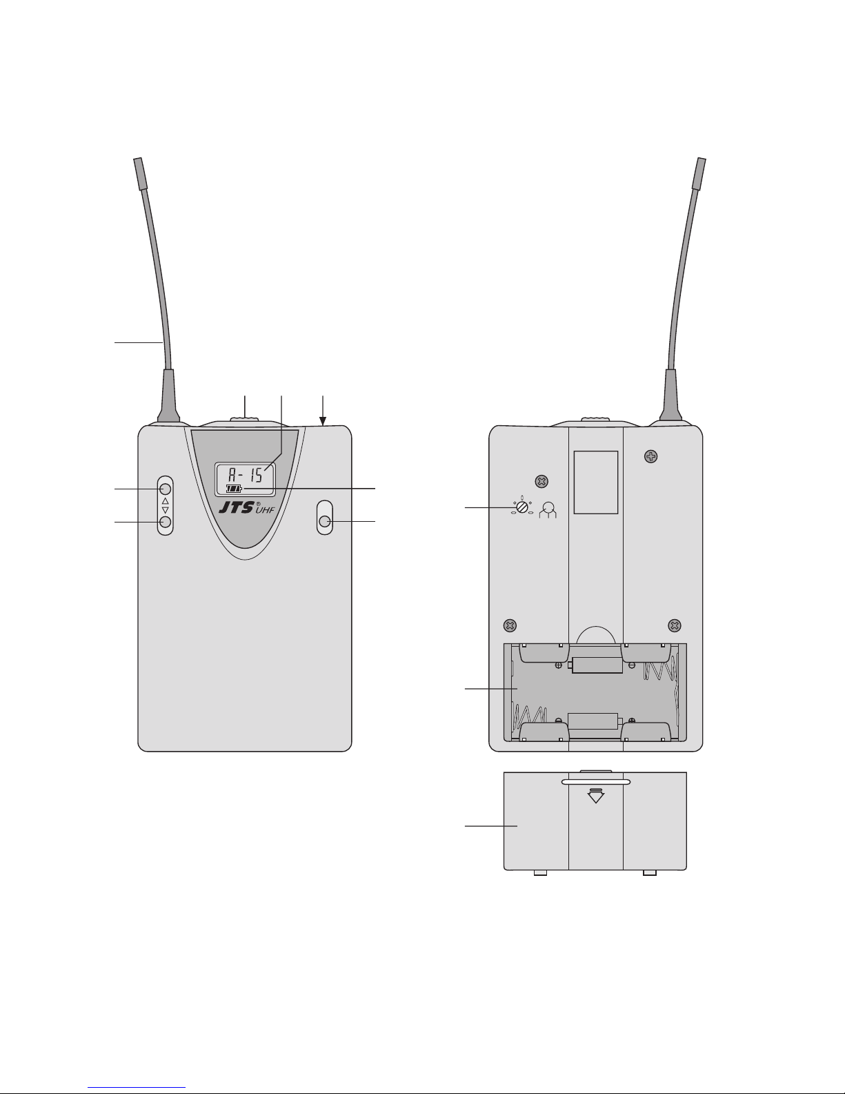
1 Übersicht der Bedienelemente und
Anschlüsse
1 Sendeantenne
2 Ein-/Ausschalter
3 Anzeige der Sendegruppe und des Übertragungs-
kanals (siehe auch Tabelle Abb. 3 auf Seite 5)
4 Mikrofonanschluss (4-polige Mini-XLR-Buchse)
5 Taste zur Aufwärtssuche für Sendegruppe/
Kanal (im Gruppen-/Kanaleinstellmodus) und zum
Aktivieren der Sperrfunktion (im Sperreinstellmodus)
6 Taste zur Abwärtssuche für Kanal/Sendegruppe
(im Gruppen-/Kanaleinstellmodus) und zum Deaktivieren der Sperrfunktion (im Sperreinstellmodus)
7 Anzeige des Batteriestatus
8 Taste SET
bei nicht gesperrtem Gerät:
zum Aufrufen und Verlassen der Einstellmodi für
Sendegruppe/Kanal, Sperrfunktion
→ Kap. 5.1 und 5.2.1
bei gesperrtem Gerät:
zum Aufrufen und Verlassen des Einstellmodus für
die Sperrfunktion → Kap. 5.2.2
9 Gain-Regler; zum Anpassen der Eingangsemp-
findlichkeit den Regler mit dem beiliegenden Einstellschlüssel drehen
10 Batteriefach für zwei 1,5-V-Batterien der Größe
Mignon (R6, AA)
11 Batteriefachdeckel
2Wichtige Hinweise für den Gebrauch
Das Gerät entspricht allen erforderlichen Richtlinien
der EU und ist deshalb mit gekennzeichnet.
●
Das Gerät ist nur zur Verwendung im Innenbereich
geeignet. Schützen Sie es vor Tropf- und Spritzwasser, hoher Luftfeuchtigkeit und Hitze (zulässiger Einsatztemperaturbereich 0 – 40°C).
●
Verwenden Sie für die Reinigung nur ein trockenes,
weiches Tuch, niemals Chemikalien oder Wasser.
●
Wird das Gerät zweckentfremdet, falsch bedient
oder nicht fachgerecht repariert, kann keine Haftung
für daraus resultierende Sach- oder Personenschäden und keine Garantie für das Gerät übernommen
werden.
3 Einsatzmöglichkeiten
Dieser Multifrequenz-Taschensender bildet mit dem
Multifrequenz-Empfänger US-903DC PRO von JTS
ein drahtloses Audio-Übertragungssystem. Der Sender arbeitet mit vier Sendegruppen (A – D), denen
jeweils 16 Übertragungskanäle zugeordnet sind. Insgesamt stehen also 64 werkseitig eingestellte Übertragungskanäle zur Verfügung. Diese Kanäle im UHFBereich von 790 – 814 MHz können frei ausgewählt
werden.
Der Taschensender wird mit dem Lavaliermikrofon
CM-501 geliefert. Anstelle des CM-501 können auch
aus dem Programm von JTS z. B. die Kopfbügelmikrofone CM-204… und CX-504 oder die Instrumentenmikrofone CX-508W und CX-516W verwendet werden.
3.1 Konformität und Zulassung des Senders
Der Taschensender ist nach den einschlägigen Normen der R + TTE-Richtlinie geprüft. Die Konformitätserklärung kann im Internet auf der Homepage von JTS
(www.jts-germany.de) abgerufen werden.
Der Frequenzbereich 790 – 814 MHz ist in Deutschland allgemein zugeteilt, die Allgemeinzuteilung einzelner Frequenzen des Bereichs ist jedoch an die Art
der Nutzung gebunden. Der Sender ist dementsprechend anmelde- und gebührenfrei, sofern bei der
Wahl der Sendefrequenz die Vorgaben der Verfügung
91/2005 beachtet werden. Sie finden die Verfügung
im Internet auf der Homepage der Bundesnetzagentur: www.bundesnetzagentur.de
Da für Funksysteme, die in diesem Frequenzbereich arbeiten, in anderen Ländern eventuell andere
gesetzliche Bestimmungen gelten, informieren Sie
sich vor der Inbetriebnahme des Systems außerhalb
Deutschlands bitte bei der MONACOR-Niederlassung
oder der entsprechenden Behörde des Landes.
4 Stromversorgung
●
Setzen Sie nur Batterien des gleichen Typs ein und
tauschen Sie die Batterien immer komplett aus.
●
Nehmen Sie bei längerem Nichtgebrauch (z. B. län-
ger als eine Woche) die Batterien heraus. So bleibt
das Gerät bei einem eventuellen Auslaufen der
Batterien unbeschädigt.
Soll das Gerät endgültig aus dem Betrieb
genommen werden, übergeben Sie es zur
umweltgerechten Entsorgung einem örtlichen Recyclingbetrieb.
Werfen Sie verbrauchte Batterien bzw. defekte Akkus
nicht in den Hausmüll, sondern geben Sie sie nur
in den Sondermüll (z. B. Sammelbehälter bei Ihrem
Einzelhändler).
DEUTSCH
Page 5

5
1) Den Klettverschluss öffnen und den Sender aus
der Gürteltasche nehmen.
2) Den Batteriefachdeckel (11) abnehmen. Das Batteriefach (10) ist dann zugänglich.
3) Zwei 1,5-V-Batterien der Größe Mignon (R6, AA),
mit den Plus- und Minusanschlüssen wie im Batteriefach aufgedruckt, einsetzen.
4) Den Deckel wieder aufsetzen.
5 Inbetriebnahme
1) Das beiliegende Lavaliermikrofon CM-501 an die
Mini-XLR-Buchse INPUT (4) anschließen und es
mit der Klemme an der Kleidung befestigen (z. B.
an der Krawatte oder am Revers).
Es kann aber auch ein anderes passendes JTSMikrofon mit 4-poligem Mini-XLR-Stecker verwendet werden (siehe Kapitel 3).
2) Den Taschensender noch ausgeschaltet lassen.
Zuerst den Empfänger auf einen störungsfreien
Übertragungskanal einstellen, siehe Bedienungsanleitung des Empfängers.
3) Danach den Sender einschalten: Den Ein-/Ausschalter (2) in die Position ON schieben. Im Display
erscheint die eingestellte Sendegruppe mit entsprechendem Übertragungskanal (3) und ein Batteriesymbol (7), das den aktuellen Ladezustand der
Batterien in mehreren Stufen anzeigt:
voll erschöpft
4) Den Sender auf die gleiche Sendegruppe und den
gleichen Übertragungskanal wie am Empfänger
einstellen → Kapitel 5.1.
5) In das angeschlossene Mikrofon sprechen oder
singen. Durch Verändern der Empfindlichkeit über
den Trimmregler GAIN (9) auf der Rückseite des
Bedienteils (Abb. 2) lässt sich der Lautstärkepegel
korrigieren. Dazu den beiliegenden Einstellschlüssel verwenden. Den Sender nach der Anzeige AF
im Display des Empfängers auf optimalen Pegel
einstellen. Bei zu hohem Pegel verzerrt der Sender,
dann den Regler zurückdrehen (ggf. auch ganz
nach links). Bei zu geringem Pegel ergibt sich ein
schlechter Rauschabstand, den Regler dann entsprechend aufdrehen.
6) Der Sender kann gesperrt werden, um ein versehentliches Verändern des Übertragungskanals
oder um ein Ausschalten zu verhindern → Kap. 5.2.
7) Nach dem Durchführen aller Einstellungen den Sender wieder in die Gürteltasche stecken und mit dem
Klettverschluss gegen Herausrutschen sichern.
8) Den Sender mit der Klettgürtellasche an der Kleidung befestigen, z. B. am Gürtel.
9) Zum Ausschalten des Senders nach dem Betrieb
den Ein-/Ausschalter (2) auf OFF stellen. Das Display zeigt kurz und erlischt dann ganz.
5.1 Einstellen der Sendegruppe und des Übertragungskanals
1) Die Taste SET (8) 2 s gedrückt halten, bis das Dis-
play kurz anzeigt. Anschließend blinkt die
Gruppenanzeige , , oder .
Hinweis: Um den Einstellmodus ohne eine Einstel-
lung zu verlassen, die Taste SET so oft drücken,
bis im Display erscheint. Das Gerät
schaltet danach auf normalen Betrieb zurück.
2) Mit den Pfeiltasten die Sendegruppe einstellen: mit
der Taste (6) werden die Gruppen absteigend
durchlaufen, mit der Taste (5) aufsteigend. Die
zugehörigen Kanäle und Sendefrequenzen sind in
der Tabelle Abb. 4 angegeben.
Hinweis: Bei gleichzeitiger Verwendung anderer
Funksysteme sollten die Funkfrequenzen der
einzelnen Systeme sorgfältig aufeinander abgestimmt werden, um Störungen zu vermeiden.
Frequenzbeispiele für den gleichzeitigen Betrieb
mehrerer Systeme finden Sie im Internet auf
www.jts-germany.de unter „Informationen/Intermodulationsfreies Frequenzsetup“.
3) Durch erneutes Drücken der Taste SET den
Kanaleinstellmodus aufrufen. Im Display blinkt die
Kanalanzeige 1 – 16.
4) Mit den Pfeiltasten den Übertragungskanal einstel-
len: mit der Taste werden die Kanäle absteigend
durchlaufen, mit der Taste aufsteigend.
5) Die Einstellung durch Drücken der Taste SET spei-
chern. Im Display erscheint kurz , der Einstellmodus wird verlassen und das Gerät wechselt
auf den Normalbetrieb.
Abb. 3 Sendefrequenzen in MHz der Gruppen und Kanäle
DEUTSCH
®
Gruppe
Kanal
A B C D
1 790,875 790,750 791,125 790,625
2 792,625 791,375 791,750 791,125
3 794,250 793,125 792,625 791,875
4 795,625 794,000 793,750 793,625
5 797,125 795,250 794,500 795,875
6 798,875 796,250 796,125 797,125
7 801,125 796,875 796,875 797,875
8 802,250 798,000 798,250 799,125
9 803,625 798,875 799,000 800,875
10 805,250 800,250 800,875 801,375
11 805,750 803,250 804,500 802,875
12 808,625 804,000 805,875 803,375
13 809,125 805,625 806,625 804,125
14 810,000 806,750 807,750 806,250
15 813,250 808,250 808,375 807,625
16 813,750 813,750 813,750 813,625
Page 6

6
5.2 Gerät sperren/entsperren
Bei gesperrtem Gerät ist es nicht möglich,
a das Gerät auszuschalten; wird bei gesperrtem
Gerät der Ein- /Ausschalter (2) auf OFF gestellt,
zeigt das Display .
b den Einstellmodus für die Sendegruppe und den
Übertragungskanal aufzurufen.
5.2.1 Sperrfunktion aktivieren
1) Die Taste SET (8) 2 s gedrückt halten, bis das Display kurz anzeigt. Danach die Taste SET
noch zweimal kurz drücken, sodass im Display
blinkt (Sperrung deaktiviert).
2) Die Taste (5) drücken: Im Display blinkt .
3) Die Einstellung durch Drücken der Taste SET speichern. Im Display erscheint kurz , der Einstellmodus wird verlassen und das Gerät wechselt
auf den Normalbetrieb.
5.2.2 Sperrfunktion deaktivieren
1) Der Ein-/Ausschalter (2) muss auf ON stehen.
2) Die Taste SET (8) 3 s gedrückt halten, bis im
Display blinkt.
3) Die Taste (6) drücken: Im Display blinkt .
4) Die Einstellung durch Drücken der Taste SET speichern. Im Display erscheint kurz , der Einstellmodus wird verlassen und das Gerät wechselt
auf den Normalbetrieb.
6Technische Daten
Taschensender
Gerätetyp: . . . . . . . . . PLL-Multifrequenz-Taschen-
sender mit Pilotton
Funkfrequenzbereich: 790– 814 MHz, aufgeteilt in
64 Kanäle (→ Tabelle Abb. 3)
Audiofrequenzbereich: 40 –18 000 Hz
Frequenzstabilität: . . . ±0,005 %
Sendeleistung:. . . . . . 10 mW (EIRP)
Einsatztemperatur: . . 0 –40 °C
Stromversorgung: . . . zwei 1,5-V-Batterien der
Größe Mignon (R6, AA)
Maße: . . . . . . . . . . . . 70 x 190 x 30 mm
Gewicht:. . . . . . . . . . . 130 g
Mikrofonanschluss: . . 4-polige Mini-XLR-Buchse
1 = Masse
2 = Betriebsspannung 5 V für das Mikrofon
3 = Signaleingang
4 = Impedanzkorrektur
Lavaliermikrofon CM-501
Mikrofontyp:. . . . . . . . Elektretmikrofon
Richtcharakteristik: . . Niere
Frequenzbereich:. . . . 100 –15 000 Hz
Impedanz: . . . . . . . . . 2,2 kΩ
Empfindlichkeit: . . . . . 3,2 mV/Pa bei 1 kHz
Maximaler Schalldruck: 130 dB
Stromversorgung: . . . über den Taschensender
Anschluss: . . . . . . . . . 4-poliger Mini-XLR-Stecker
Gewicht:. . . . . . . . . . . 20 g
Änderungen vorbehalten.
2
4
1
3
DEUTSCH
Diese Bedienungsanleitung ist urheberrechtlich für MONACOR®INTERNATIONAL GmbH & Co. KG geschützt.
Eine Reproduktion für eigene kommerzielle Zwecke – auch auszugsweise – ist untersagt.
Page 7

Please unfold page 3. Then you can always see the
operating elements and connections described.
1 Operating Elements and Connections
1 Transmitting antenna
2 Power switch
3 Indication of the transmission group and the trans-
mission channel (also see table fig. 3 on page 8)
4 Microphone connection (4-pole mini XLR jack)
5 Key for scanning the transmission group /chan-
nel in ascending order (in the group adjusting
mode/channel adjusting mode) and for activating
the locking function (in the lock adjusting mode)
6 Key for scanning the transmission group /chan-
nel in descending order (in the group adjusting
mode/channel adjusting mode) and for deactivating the locking function (in the lock adjusting
mode)
7 Indication of the battery status
8 Key SET
with the unit not locked:
to recall and to exit the adjusting modes for the
transmission group/channel, locking function
→ chapters 5.1 and 5.2.1
with the unit locked:
to recall and to exit the adjusting mode for the
locking function → chapter 5.2.2
9 Gain control; for matching the input sensitivity turn
the control with the adjusting key supplied
10 Battery compartment for two 1.5 V batteries of size
AA (R6)
11 Cover of the battery compartment
2 Important Notes
The unit corresponds to all required directives of the
EU and is therefore marked with .
●
The unit is suitable for indoor use only. Protect it
against dripping water and splash water, high air
humidity, and heat (admissible ambient temperature
range 0 – 40°C).
●
For cleaning only use a dry, soft cloth; never use
chemicals or water.
●
No guarantee claims for the unit and no liability for
any resulting personal damage or material damage
will be accepted if the unit is used for other purposes
than originally intended, if it is not correctly operated
or not repaired in an expert way.
3 Applications
Together with the multifrequency receiver US-903DCPRO from JTS this multifrequency pocket transmitter
makes up a wireless audio transmission system. The
transmitter operates with four transmission groups
(A –D) to which 16 transmission channels are assigned
respectively, i. e. altogether 64 factory-set transmission
channels are available. These channels in the UHF
range of 790 – 814MHz can be selected as desired.
The pocket transmitter is supplied with the Lavalier
microphone CM-501. Instead of the CM-501 it is also
possible to use e. g. the headband microphones
CM-204... and CX-504 or the instrument microphones
CX-508W and CX-516W from the JTS product range.
3.1 Conformity and approval of the transmitter
The pocket transmitter has been tested according to
the relevant standards of the R + TTE directive. The
declaration of conformity can be found in the Internet
on the JTS home page (www.jts-germany.de).
In the Federal Republic of Germany, the frequency
range of 790 – 814 MHz is generally assigned, however, the general assignment of individual frequencies
of the range is subject to the type of use [see the directive 91/2005 on the home page of the Bundesnetzagentur (Federal Network Agency):
www.bundesnetzagentur.de].
In other countries, different legal regulations may
apply for wireless systems operating in this frequency
range. Therefore, please contact the MONACOR subsidiary or the corresponding authorities of the country
prior to setting the system into operation outside
Germany.
4 Power Supply
●
Only insert batteries of the same type and always
replace all batteries.
●
If the unit is not used for a longer period (e. g. more
than a week), remove the batteries. Thus, the unit
will not be damaged in case of battery leakage.
1) Open the Velcro fastener and take the transmitter
out of the belt bag.
If the unit is to be put out of operation definitively, take it to a local recycling plant for a
disposal which is not harmful to the environment.
Dead batteries or defective rechargeable batteries
do not belong in the household rubbish; always take
them to a special waste disposal (e. g. collecting container at your retailer).
7
ENGLISH
®
Page 8

8
2) Remove the cover (11) of the battery compartment.
Then the battery compartment (10) will be accessible.
3) Insert two 1.5 V batteries of size AA (R6) with the
positive and negative connections as indicated in
the compartment.
4) Replace the cover.
5 Setting the Transmitter into Operation
1) Connect the Lavalier microphone CM-501 supplied
to the mini XLR jack INPUT (4) and fasten it to your
clothes (e. g. tie or lapel) by means of the clip.
It is also possible to use another matching JTS
microphone with 4-pole mini XLR plug (see chapter 3).
2) Before switching on the pocket transmitter, set the
receiver to an interference-free transmission channel, see instruction manual of the receiver.
3) Then switch on the transmitter: Slide the power
switch (2) to position ON. The display will indicate
the transmission group adjusted with the corresponding transmission channel (3) and a battery
symbol (7) showing the current charging status of
the batteries in several steps:
fully charged exhausted
4) Set the transmitter to the same transmission group
and the same transmission channel adjusted on the
receiver → chapter 5.1.
5) Speak/sing into the microphone connected. The
volume level can be readjusted by changing the
sensitivity via the trimming control GAIN (9) on the
rear side of the control part (fig. 2). For this purpose, use the adjusting key supplied. Adjust the
transmitter to the optimum level according to the
indication AF on the display of the receiver. If the
level is too high, the transmitter will distort; in this
case, turn back the control (if necessary, turn it to
the left stop). If the level is too low, a poor signalnoise ratio will result; in this case advance the control correspondingly.
6) The transmitter can be locked to prevent accidental
change of the transmission channel or switching off
→ chapter 5.2.
7) After all adjustments have been made, put the
transmitter back into the belt bag and secure it
against slipping out by means of the Velcro
fastener.
8) Fasten the transmitter with the Velcro belt strap to
your clothes, e. g. belt.
9) To switch off the transmitter after operation, set the
power switch (2) to OFF. The display will shortly
show before it will be extinguished completely.
5.1 Adjusting the transmission group and the
transmission channel
1) Keep the key SET (8) pressed for 2 s until the dis-
play shortly shows . Then the group indication
, , or flashes.
Note: To exit the adjusting mode without making an
adjustment, press the key SET so many times
until the display shows .Then the unit will
return to normal operation.
2) Use the cursor keys to adjust the transmission
group: With the key (6) the groups will be scanned
in descending order, with the key (5) in ascending
order. The corresponding channels and transmission frequencies can be found in the table fig. 4.
Note: If other wireless transmission systems are
operated at the same time, the radio frequencies
of the individual systems should be carefully
matched to each other to prevent interference.
Examples for frequencies for simultaneous operation of several systems can be found in the
Internet on www.jts-germany.de under “Informationen/Intermodulationsfreies Frequenzsetup”.
3) Press the key SET again to call the channel ad-
justing mode. On the display, the channel indication
1–16 will start flashing.
4) Use the cursor keys to adjust the transmission
channel: With the key , the channels will be
scanned in descending order; with the key , they
will be scanned in ascending order.
5) To memorize the adjustment, press the key SET. The
display will shortly show , the adjusting mode
will be exited, and the unit will go to normal operation.
Fig. 3 Transmission frequencies in MHz of the groups and
channels
ENGLISH
Group
Channel
A B C D
1 790.875 790.750 791.125 790.625
2 792.625 791.375 791.750 791.125
3 794.250 793.125 792.625 791.875
4 795.625 794.000 793.750 793.625
5 797.125 795.250 794.500 795.875
6 798.875 796.250 796.125 797.125
7 801.125 796.875 796.875 797.875
8 802.250 798.000 798.250 799.125
9 803.625 798.875 799.000 800.875
10 805.250 800.250 800.875 801.375
11 805.750 803.250 804.500 802.875
12 808.625 804.000 805.875 803.375
13 809.125 805.625 806.625 804.125
14 810.000 806.750 807.750 806.250
15 813.250 808.250 808.375 807.625
16 813.750 813.750 813.750 813.625
Page 9

5.2 Locking/ Unlocking the unit
With the unit locked, it is not possible
a to switch off the unit; if the power switch (2) is set to
OFF with the unit locked, the display will show
.
b to recall the adjusting mode for the transmission
group and the transmission channel.
5.2.1 Activating the locking function
1) Keep the key SET (8) pressed for 2 s until the display shortly indicates . Then shortly press the
key SET twice again so that flashes on the
display (locking deactivated).
2) Press the key (5): flashes on the display.
3) To memorize the adjustment, press the key SET.
The display will shortly indicate , the adjusting
mode will be exited, and the unit will go to normal
operation.
5.2.2 Deactivating the locking function
1) The power switch (2) must be set to ON.
2) Keep the key SET (8) pressed for 3 s until
flashes on the display.
3) Press the key (6): starts flashing on the
display.
4) To memorize the adjustment, press the key SET.
The display will shortly indicate , the adjusting
mode will be exited, and the unit will go to normal
operation.
6 Specifications
Pocket transmitter
Type of unit:. . . . . . . . PLL multifrequency pocket
transmitter with pilot tone
Radio frequency
range: . . . . . . . . . . . . 790 –814 MHz, divided into
64 channels (→ table fig. 3)
Audio frequency
range: . . . . . . . . . . . . 40 – 18000 Hz
Frequency stability: . . ±0.005 %
Transmitting power:. . 10 mW (EIRP)
Ambient temperature: 0 – 40°C
Power supply: . . . . . . two 1.5 V batteries
of size AA (R6)
Dimensions:. . . . . . . . 70 x 190 x 30 mm
Weight: . . . . . . . . . . . 130 g
Microphone
connection: . . . . . . . . 4-pole mini XLR jack
1 = ground
2 = 5 V operating voltage for the microphone
3 = signal input
4 = impedance matching
Lavalier microphone CM-501
Microphone type:. . . . electret microphone
Directivity: . . . . . . . . . cardioid
Frequency range: . . . 100 –15 000 Hz
Impedance: . . . . . . . . 2.2 kΩ
Sensitivity: . . . . . . . . . 3.2 mV/Pa at 1 kHz
Max. SPL: . . . . . . . . . 130 dB
Power supply: . . . . . . via the pocket transmitter
Connection: . . . . . . . . 4-pole mini XLR plug
Weight: . . . . . . . . . . . 20 g
Subject to technical modification.
2
4
1
3
9
ENGLISH
®
All rights reserved by MONACOR®INTERNATIONAL GmbH & Co. KG. No part of this instruction manual may
be reproduced in any form or by any means for any commercial use.
Page 10

Copyright©by MONACOR INTERNATIONAL GmbH & Co. KG, Bremen, Germany. All rights reserved. A-0629.99.01.06.2006
www.jts-germany.de
 Loading...