

Page 1
Bedienungsanleitung
Instruction Manual
Vertrieb von JTS-Produkten — Distribution of JTS products
KA-10/1PACK
®
Audio-Funkübertragungssystem für Kameras
Audio Transmission System for Cameras
Page 2

2
DEUTSCHENGLISH
Bevor Sie einschalten …
Wir wünschen Ihnen viel Spaß mit Ihrem
neuen Gerät von JTS. Bitte lesen Sie diese
Bedienungsanleitung vor dem Betrieb gründlich durch. Nur so lernen Sie alle Funktionsmöglichkeiten kennen, vermeiden Fehlbedienungen und schützen sich und Ihr Gerät
vor eventuellen Schäden durch unsachgemäßen Ge brauch. Heben Sie die Anleitung
für ein späteres Nach lesen auf.
Der deutsche Text beginnt auf der Seite 4.
Before switching on …
We wish you much pleasure with your new
JTS unit. Please read these operating in structions carefully prior to operating the unit.
Thus, you will get to know all functions of the
unit, op er ating errors will be prevented, and
yourself and the unit will be protected against
any damage caused by improper use. Please
keep the operating instructions for later use.
The English text starts on page 8.
Page 3
CHANNEL
POWER
RESET
MIC/LINE
MIC
GAIN
POWER
RESET
AF OUT
CHANNEL
PAD
3
123 4 123 4
12V 500mA
TG-10CH2
POWER
RESET
MIC/LINE
POWER
RESET
AF OUT
13 14 13 14
Sender
Transmitter
Empfänger
Receiver
5
6
7
8
5
6
7
8
910
Ladestation
Charger
Powered by 3.7V Lithium ion Battery
Befestigungsschuh
Shoe mount adapter
11 12
Page 4
DEUTSCH
4
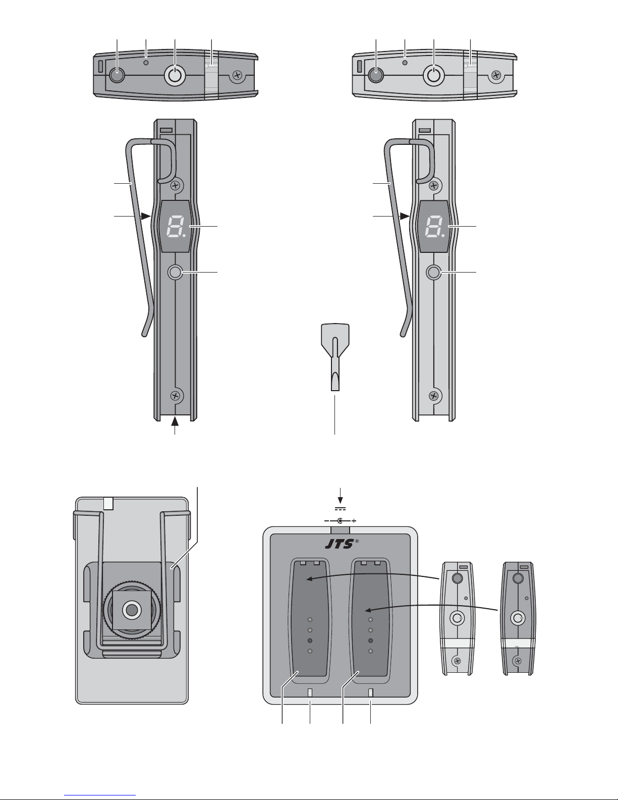
Auf der ausklappbaren Seite 3 finden Sie alle be schriebenen Bedienelemente und Anschlüsse.
1 Übersicht der Bedienelemente
und Anschlüsse
1.1 Sender und Empfänger
1 3,5-mm-Klinkenbuchse
am Sender als Audioeingang zum Anschluss
des beiliegenden Krawattenmikrofons oder
eines Audiogerätes mit Line-Ausgang (CD/
MP3-Spieler, Radio, Mischpult etc.)
am Empfänger als Audioausgang zum An -
schluss an das nachfolgende Gerät (Kamera,
Verstärker, Mischpult etc.)
2 Reset-Taste
3 Ein-/Ausschalttaste POWER
Zum Einschalten genügt ein Antippen; zum Ausschalten die Taste 3 s gedrückt halten, bis die
Betriebsanzeige (4) erlischt.
4 Betriebsanzeige
grün = Akku ausreichend geladen
rot = Akku muss aufgeladen werden
5 Klemmbügel
6 auf der Rückseite
am Sender Regler GAIN für die Lautstärke des
gesendeten Tonsignals
am Empfänger Drehschalter PAD für den Aus-
gangspegel der Buchse AF OUT (1)
7 Display, zeigt den Übertragungskanal an
Damit das Display einige Sekunden lang leuchtet, die Taste POWER (3) oder CHANNEL (8)
kurz drücken.
8 Taste CHANNEL zum Einstellen des Übertra-
gungskanals
9 Mikrofon im Sender
10 Einstellschlüssel
11 Befestigungsschuh, festgeklemmt durch den
Bügel (5)
1.2 Ladestation
12 Buchse für das beiliegende Netzgerät
13 Ladeschacht
14 Ladeanzeige
2 Hinweise für den sicheren Gebrauch
Die Geräte (Sender, Empfänger, Ladestation und
Netzgerät) entsprechen allen relevanten Richt linien der EU und sind deshalb mit gekennzeichnet.
G
Die Geräte sind nur zur Verwendung im Innenbereich geeignet. Schützen Sie sie vor Tropf- und
Spritzwasser, hoher Luftfeuchtigkeit und Hitze
(zulässiger Einsatztemperaturbereich 0 – 40 °C).
G
Nehmen Sie das Ladegerät nicht in Betrieb und
ziehen Sie sofort das Netzgerät aus der Steckdose,
1. wenn sichtbare Schäden an den Geräten vorhanden sind,
2. wenn nach einem Sturz oder Ähnlichem der
Verdacht auf einen Defekt besteht,
3. wenn Funktionsstörungen auftreten.
Geben Sie die Geräte in jedem Fall zur Reparatur in eine Fachwerkstatt.
G
Verwenden Sie für die Reinigung nur ein trockenes, weiches Tuch, niemals Wasser oder Chemikalien.
G
Werden die Geräte zweckentfremdet, nicht richtig angeschlossen, falsch bedient oder nicht
fachgerecht repariert, kann keine Haftung für
daraus resultierende Sach- oder Personenschäden und keine Garantie für die Geräte übernommen werden.
3 Verwendungsmöglichkeiten
Dieses Audio-Übertragungssystem ersetzt das
Verbindungskabel, das von einem Mikrofon zu
einer Videokamera führt. Das Mikrofonsignal wird
vom Sender zum Empfänger gefunkt. Der Video filmer kann sich so ohne einschränkendes Kabel
frei bewegen. Anstelle des beiliegendenen Senders kann auch das Funkmikrofon KA-8TH /1
(Bestell-Nr. 25.4410) verwendet werden. Außerdem lässt sich das KA-10 / 1PACK zur drahtlosen
Übertragung von Line-Audiosignalen nutzen.
Sollen die Geräte endgültig aus dem
Betrieb genommen werden, übergeben
Sie sie zur umweltgerechten Entsorgung
einem örtlichen Recyclingbetrieb.
WARNUNG Das Netzgerät wird mit lebensge-
fährlicher Netzspannung versorgt.
Nehmen Sie deshalb niemals selbst
Eingriffe daran vor. Durch unsachgemäßes Vorgehen besteht die Gefahr
eines elektrischen Schlages.
Page 5

DEUTSCH
5
Für die Funkübertragung stehen 16 Kanäle im
Frequenzbereich 863 – 865 MHz zur Verfügung,
von denen bis zu 3 Kanäle gleichzeitig genutzt werden können, ohne sich gegenseitig zu stören. Die
Übertragungsreichweite hängt von den örtlichen
Gegebenheiten ab und kann bis zu 60 m betragen.
3.1 Konformität und Zulassung
Hiermit erklärt MONACOR INTERNATIONAL, dass
sich der Sender des Übertragungssystems KA-10 /
1PACK in Übereinstimmung mit den grundlegenden Anforderungen und den übrigen einschlägigen
Be stimmungen der Richtlinie 1999 / 5 / EG befindet.
Die Konformitätserklärung kann bei MONACOR
INTERNATIONAL angefordert werden.
Das Übertragungssystem ist für den Betrieb in den
EU- und EFTA- Staaten allgemein zugelassen und
anmelde- und gebührenfrei.
4 Akkus aufladen
Der Sender und der Empfänger werden über einen
eingebauten Lithium-Ionen-Akku mit Strom versorgt. Vor der ersten Inbetriebnahme die Akkus voll
aufladen:
1) Das beiliegende Netzgerät an die Buchse „12 V/
500 mA“ (12) der Ladestation anschließen und
das Netzgerät in eine Steckdose (230 V~ /
50 Hz) stecken. Die Ladeanzeigen (14) blinken,
solange die Ladeschächte (13) leer sind.
2) Den Sender und den Empfänger in die Lade-
schächte stecken, siehe Abb. 4. Nach einigen
Sekunden leuchten die Ladeanzeigen auf.
Leuchten sie nicht, die Geräte tiefer hinein stecken.
3) Ist der Akku eines Gerätes aufgeladen, erlischt
die zugehörige Ladeanzeige. Das Gerät kann
herausgezogen werden.
4) Nach dem Aufladen der Akkus das Netzgerät
der Ladestation aus der Steckdose ziehen.
Hinweise
– Blinkt eine Ladeanzeige während des Ladens,
führt die Ladestation zum Schutz des Akkus
einen Selbsttest durch.
– Für eine lange Lebensdauer der Akkus die
Geräte nicht mit entladenem Akku lagern und
bei längerem Nichtgebrauch die Akkus alle drei
Monate nachladen.
– Einen defekten Akku nur durch eine Fachkraft
auswechseln lassen, weil das Gerät dazu geöff-
net werden muss. Ein passender Ersatzakku ist
unter der Bezeichnung TG-3.7VB (Bestell-Nr.
28.2460) erhältlich.
5 Geräte befestigen und anschließen
Zur Unterscheidung hat der Sender ein schwarzes
Gehäuse mit großem T auf der Vorderseite und der
Empfänger ein graues Gehäuse mit großem R.
1) Der Sender und der Empfänger besitzen zur
Be festigung je einen Klemmbügel (5). Mit dem
Bügel lassen sich die Geräte z. B. an der Kleidung (am Gürtel oder an der Hosentasche) festklemmen.
Alternativ lässt sich eines der Geräte mit
dem beiliegenden Befestigungsschuh (11) auf
eine Kamerahalterung mit 6,3-mm-Fotoge winde (
1
⁄4″) schrauben. Der Empfänger kann
aber auch mit dem Befestigungsschuh auf die
Aufnahmelicht- / Blitzlichthalterung der Kamera
montiert werden. Den Befestigungsschuh unter
den Bügel des Senders bzw. des Empfängers
klemmen (Abb. 3).
2) Der Sender hat ein Mikrofon (9) eingebaut, mit
dem der Ton aufgenommen werden kann. Es
lässt sich aber auch das beiliegende Krawattenmikrofon an die Buchse MIC / LINE (1) anschließen; das eingebaute Mikrofon wird dabei abgeschaltet. Bei Bedarf den beiliegenden Windund Poppschutz auf das Krawattenmikrofon
stecken. Zum Befestigen des Mikrofons (z. B.
an der Krawatte) die beiliegende Klammer an
das Mikrofonkabel klemmen.
Soll das KA-10 / 1PACK zur drahtlosen Übertragung von Line-Audiosignalen ge nutzt werden, an die Buchse MIC / LINE die Audioquelle
(CD/ MP3-Spieler, Radio, Mischpult etc.) an schließen.
3) Die Buchse AF OUT (1) des Empfängers mit
dem Audio-Eingang der Kamera oder des nachfolgenden Gerätes (Verstärker, Mischpult etc.)
verbinden. Ein An schlusskabel mit zwei 3,5-mmKlinkensteckern und ein Adapterkabel (3,5-mmKlinkenstecker auf XLR-Stecker) liegen bei.
Defekte Akkus dürfen nicht in den Hausmüll geworfen werden. Geben Sie sie zur
umweltgerechten Entsorgung nur in den
Sondermüll (z. B. Sammelbehälter bei
Ihrem Fachändler).
Page 6

DEUTSCH
6
6 Betrieb
1) Zum Einschalten der Geräte die Taste
POWER (3) drücken. Die Betriebsanzeige (4)
leuchtet grün. Leuchtet sie rot, ist der Akku fast
leer und sollte möglichst schnell wieder aufgeladen werden.
Das Display (7) zeigt für einige Sekunden
den eingestellten Übertragungskanal an, dann
erlischt es. Durch Drücken der Taste POWER
oder CHANNEL (8) leuchtet es wieder für einige
Sekunden.
2) Den Übertragungskanal aus den verfügbaren
Kanälen 0 bis F auswählen (siehe Tabelle
unten). Den Sender und den Empfänger auf
den gleichen Kanal einstellen. Dazu die Taste
CHANNEL (8) so lange gedrückt halten, bis im
Display ein Punkt blinkt. Dann die Taste CHANNEL so oft drücken, bis der gewünschte Kanal
angezeigt wird. Der gewählte Kanal ist gespeichert, wenn ca. 6 Sekunden nach der letzten
Betätigung der Taste CHANNEL der Punkt im
Display erlischt.
3) Die Lautstärke für das gesendete Tonsignal mit
dem Regler GAIN (6) am Sender einstellen.
Dazu den Einstellschlüssel (10) zu Hilfe nehmen. Bei zu hoher Lautstärke verzerrt das Signal, dann den Regler nach links drehen. Bei zu
geringer Lautstärke ergibt sich ein schlechter
Rauschabstand, dann den Regler nach rechts
drehen.
4) Am Empfänger den Ausgangspegel der Buchse
AF OUT (1) mit dem Drehschalter PAD (6) an
das angeschlossene Gerät anpassen. Dazu
den Einstellschlüssel (10) zu Hilfe nehmen. Der
Schalter hat 3 Stufen: 0 dB,
-
10 dB und -20 dB.
5) Ist der Empfang schlecht oder gestört, überprüfen ob:
– auf einem anderen Kanal die Übertragung
besser ist.
– der Abstand zwischen Sender und Empfän-
ger zu groß ist.
– sich Hindernisse in der Übertragungsstrecke
befinden, die das Funksignal abschirmen
können.
6) Zum Zurücksetzen eines Geräts bei Funktionsstörungen kann mit einem dünnen Gegenstand,
z. B. Metallstift, die Taste RESET (2) betätigt
werden. Das Gerät schaltet sich dann aus und
kann erneut in Betrieb genommen werden.
7) Zum Ausschalten der Geräte die Taste
POWER so lange gedrückt halten, bis die
Betriebsanzeige erlischt.
7 Technische Daten
Funkfrequenzbereich: . . 863 – 865 MHz
Kanalbelegung siehe
Tabelle unten
Sendeleistung: . . . . . . . . < 10 mW (EIRP)
Reichweite: . . . . . . . . . . . ca. 60 m
Audiofrequenzbereich: . . 40 – 18 000 Hz
Ausgangspegel: . . . . . . . max. 850 mV,
absenkbar auf
-
10 dB oder -20 dB
Mikrofon im Sender: . . . . Elektretmikrofon mit
Nierencharakteristik
Krawattenmikrofon: . . . . Elektretmikrofon mit
Nierencharakteristik
Einsatztemperatur: . . . . . 0 – 40 °C
Stromversorgung
Sender, Empfänger: . . Lithium-Ionen-Akku
3,7 V/1300 mAh
Ladestadion: . . . . . . . . 12 V über beiliegen-
des Netzgerät an
230 V~ / 50 Hz
Akku-Betriebszeit: . . . . . ca. 14 Stunden
Abmessungen, Gewicht
Sender, Empfänger: . . 54 × 99 × 17 mm, 80 g
Ladestation: . . . . . . . . 75 × 41 × 85 mm, 115 g
Kanalbelegung
Änderungen vorbehalten.
Kanal MHz Kanal MHz
0 863,125 A 864,375
1 863,250 B 864,500
2 863,375 C 864,625
3 863,500 D 864,750
4 863,625 E 864,875
5 863,750 F 865,000
6 863,875
7 864,000
8 864,125
9 864,250
Diese Bedienungsanleitung ist urheberrechtlich für MONACOR®INTERNATIONAL GmbH & Co. KG ge schützt.
Eine Reproduktion für eigene kommerzielle Zwecke – auch auszugsweise – ist untersagt.
Page 7

7
Page 8
All operating elements and connections de scribed can be found on the fold-out page 3.
1 Operating Elements
and Connections
1.1 Transmitter and receiver
1 3.5 mm jack
on the transmitter: as an audio output to connect
the supplied tie clip microphone or an audio
unit with line output (CD / MP3 player, radio,
mixer etc.)
on the receiver: as an audio output to connect the
following unit (camera, amplifier, mixer etc.)
2 RESET button
3 On / off button POWER
To switch on, briefly press the button; to switch
off, keep the button pressed for 3 seconds until
the power LED (4) is extinguished
4 Power LED
green = battery charged sufficiently
red = battery discharged
5 Clip
6 on the back
of the transmitter: control GAIN for the volume
of the audio signal transmitted
of the receiver: rotary switch PAD for the output
level of the jack AF OUT (1)
7 Display, to indicate the transmission channel
To illuminate the display for a few seconds,
press the button POWER (3) or CHANNEL (8)
briefly.
8 Button CHANNEL to set the transmission chan-
nel
9 Microphone in the transmitter
10 Adjusting key
11 Shoe mount adapter, held in place by the clip (5)
1.2 Charger
12 Jack to connect the power supply unit provided
13 Charging slot
14 Charging LED
2 Safety Notes
The units (transmitter, receiver, charger and power
supply unit) correspond to all relevant directives of
the EU and are therefore marked with .
G
The units are suitable for indoor use only. Protect
them against dripping water and splash water,
high air humidity and heat (admissible ambient
temperature range: 0 – 40 °C).
G
Do not operate the charger and immediately disconnect the power supply unit from the socket
1. if the units are visibly damaged,
2. if a defect might have occurred after a unit was
dropped or suffered a similar accident,
3. if malfunctions occur.
In any case the units must be repaired by skilled
personnel.
G
For cleaning only use a dry, soft cloth; never use
water or chemicals.
G
No guarantee claims for the units and no liability
for any resulting personal damage or material
damage will be accepted if the units are used for
other purposes than originally intended, if they
are not correctly connected or operated, or if they
are not repaired in an expert way.
3 Applications
This audio transmission system can be used to
replace the connection cable between a microphone and a video camera. The transmitter sends a
wireless microphone signal to the receiver. The user
of the video camera is free to move as desired without being restricted by a cable. Instead of the supplied transmitter, it is also possible to use the wireless microphone KA-8TH /1 (order no. 25.4410).
The system KA-10 /1PACK is also suitable for wireless transmission of line audio signals.
If the units are to be put out of operation
definitively, take them to a local recycling
plant for a disposal which is not harmful to
the environment.
WARNING
The power supply unit uses dangerous mains voltage. Leave servicing
to skilled personnel only. Inexpert
handling may result in electric shock.
8
ENGLISH
Page 9

For wireless transmission, 16 channels are
available in the frequency range 863 – 865MHz.
Up to three of these channels can be used at the
same time without mutual interference. The transmission range depends on local conditions and
may reach 60 m as a maximum.
3.1 Conformity and approval
Herewith, MONACOR INTERNATIONAL declare
that the transmitter of the transmission system
KA-10/1PACK is in accordance with the basic
requirements and the other relevant regulations of
the directive 1999 / 5 / EC. The declaration of conformity is available on request from MONACOR
INTERNATIONAL.
The transmission system is licence-free and generally approved for operation in EU and EFTA
countries.
4 Charging the Batteries
The transmitter and the receiver are supplied with
power via a built-in rechargeable lithium-ion battery: Prior to initial operation, fully recharge the batteries.
1) Connect the power supply unit provided to the
jack “12 V/ 500 mA” (12) of the charger, then
connect the power supply unit to a mains socket
(230 V~ / 50Hz). The charging LEDs (14) keep
flashing as long as the charging slots (13) are
empty.
2) Insert the transmitter and the receiver into the
charging slots according to fig. 4. After a few
seconds, the charging LEDs light up. If they fail
to light up, push the units deeper into the slots.
3) When the battery of a unit has been fully
recharged, the corresponding charging LED is
extinguished. The unit can be removed from the
slot.
4) After the batteries have been charged, discon-
nect the power supply unit of the charger from
the mains socket.
Notes
– If a charging LED keeps flashing during the
charging process, the charger performs a selftest to protect the batteries.
– To ensure a long battery life, do not store the
units with discharged batteries. If the units are
not used for a longer period, recharge the batteries every three months.
– To replace the battery, the unit must be opened.
Therefore, a defective battery must always be
replaced by skilled personnel. A suitable
replacement battery is available: TG-3.7VB
(order no. 28.2460).
5 Fastening and Connecting the Units
For a better distinction between the units, the housing of the transmitter is black and marked with a
large T at the front; the housing of the receiver is
grey and marked with a large R.
1) The transmitter and the receiver are both provided with a clip (5). This clip can be used to fasten the units on your clothes, e. g. belt or trouser
pocket.
Alternatively, use the supplied shoe mount
adapter (11) to screw one of the units onto a
camera support with 6.3 mm thread (
1
⁄4″). The
adapter can also be used to mount the receiver
on the shoe for the video light / flash unit of the
camera. To hold the shoe mount adapter in
place, put it under the clip of the transmitter or
the receiver (fig. 3).
2) The transmitter is equipped with a built-in microphone (9) to pick up the sound. It is also possible to connect the supplied tie clip microphone
to the jack MIC / LINE (1); in this case, the builtin microphone is switched off. If required, put
the supplied windshield / pop shield on the tie
clip microphone. To attach the microphone, e. g.
to your tie, fasten the supplied clip to the microphone cable.
If the KA-10 /1PACK is used for wireless
transmission of line audio signals, connect the
audio source (CD / MP3 player, radio, mixer etc.)
to the jack MIC / LINE.
3) Connect the jack AF OUT (1) of the receiver to
the audio input of the camera or the following
unit (amplifier, mixer etc.). A connection cable
with two 3.5 mm plugs and an adapter cable
(3.5 mm plugs to XLR plugs) is supplied with the
system.
Never put defective batteries in the household waste; always take them to a special
waste disposal, e. g. collection container at
your retailer.
9
ENGLISH
Page 10

6 Operation
1) To switch on the units, press the button #
POWER (3). The power LED (4) shows green. If
it shows red, the battery is almost discharged
and should be recharged as soon as possible.
The display (7) indicates the transmission
channel adjusted for a few seconds. Then it is
extinguished. To illuminate the display for a few
seconds, press the button POWER or CHANNEL (8).
2) Select a transmission channel from the chan-
nels available (0 to F, see table below). Set the
transmitter and the receiver to the same channel: Keep the button CHANNEL (8) pressed
until a dot starts flashing on the display. Then
press the button CHANNEL repeatedly until the
desired channel is indicated. The channel
selected has been stored when the dot on the
display disappears (approx. 6 seconds after the
last actuation of the button CHANNEL).
3) Adjust the volume for the audio signal transmitted with the control GAIN (6) on the transmitter.
For this purpose, use the adjusting key (10). If
the volume is too high, the signal will distort; in
this case, turn the control counterclockwise. If
the volume is too low, there will be a poor signalto-noise ratio; in this case, turn the control clockwise.
4) On the receiver, use the rotary switch PAD (6) to
match the output level of the jack AF OUT (1) to
the unit connected. For this purpose, use the
adjusting key (10). The switch has 3 levels:
0 dB,
-
10 dB and -20 dB.
5) If the reception is poor or disturbed, please
check
– if the transmission is better when a different
channel is used.
– if the transmitter and the receiver are too far
apart.
– if there are obstacles in the transmission
path which may shield the radio signal.
6) To reset a unit in case of malfunction, press the
button RESET (2) by means of a thin object,
e. g. a metal pin. The unit is switched off and can
be set into operation again.
7) To switch off the units, keep the button
POWER pressed until the power LED is extinguished.
7 Specifications
Radio frequency range: . 863 – 865 MHz
for channel assignment
see table below
Transmission power: . . . < 10 mW (EIRP)
Range: . . . . . . . . . . . . . . approx. 60 m
Audio frequency range: . 40 – 18 000 Hz
Output level: . . . . . . . . . . 850 mV max.,
can be reduced to
-
10 dB or -20 dB
Microphone in the
transmitter. . . . . . . . . . . . electret microphone,
cardioid
Tie clip microphone: . . . . electret microphone,
cardioid
Ambient temperature: . . . 0 – 40 °C
Power supply
Transmitter, receiver: . rechargeable lithium-
ion battery
3.7 V/1300 mAh
Charger: . . . . . . . . . . . 12 V via power supply
unit provided,
connected to
230 V~ / 50 Hz
Operating time of battery: approx. 14 hours
Dimensions, weight:
Transmitter, receiver: . 54 × 99 × 17 mm, 80 g
Charger: . . . . . . . . . . . 75 × 41 × 85 mm, 115 g
Channel assignment
Subject to technical modification.
Channel MHz Channel MHz
0 863.125 A 864.375
1 863.250 B 864.500
2 863.375 C 864.625
3 863.500 D 864.750
4 863.625 E 864.875
5 863.750 F 865.000
6 863.875
7 864.000
8 864.125
9 864.250
10
ENGLISH
All rights reserved by MONACOR®INTERNATIONAL GmbH & Co. KG. No part of this instruction manual may
be reproduced in any form or by any means for any commercial use.
Page 11

11
Page 12

www.jts-germany.de
MONACOR INTERNATIONAL GmbH & Co. KG, Zum Falsch 36, 28307 Bremen, Germany
Copyright
©
by MONACOR INTERNATIONAL. All rights reserved. A-1437.99.01.06.2013
 Loading...