

Page 1
Bedienungsanleitung
Instruction Manual
Mode d‘emploi
Manual de Instrucciones
Vertrieb von JTS-Produkten – Distrubution of JTS products
JSS-20/5
Dynamisches Funkmikrofon
Wireless dynamic microphone
Microphone dynamique sans fil
Micrófono dinámico inalámbrico
Bestell-Nr. • Order No. 25.7200
530 – 605 MHz
Page 2

2
Page 3

Deutsch . . . . Seite 4
English. . . . . Page 12
Français . . . . Page 20
Español . . . . Página 28
3
Page 4

10
Deutsch
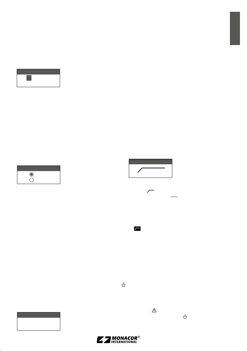
Abb. 1 Menü
Abb. 2 JSS-20/5
1
Ni-MHNi-MH
1. Frequency
2. Group/Channel
3. Sensitivity
4. Low Cut
5. Device ID
6. Remoset
7. RF Power
8. Contrast
9. Light Time
a. User Name
c. Reset
d. KeyLock
e. Exit
2
Lo
JSS-20
G:2 C:1
530.375 MHz
0dB ID1
LED
3
4
5
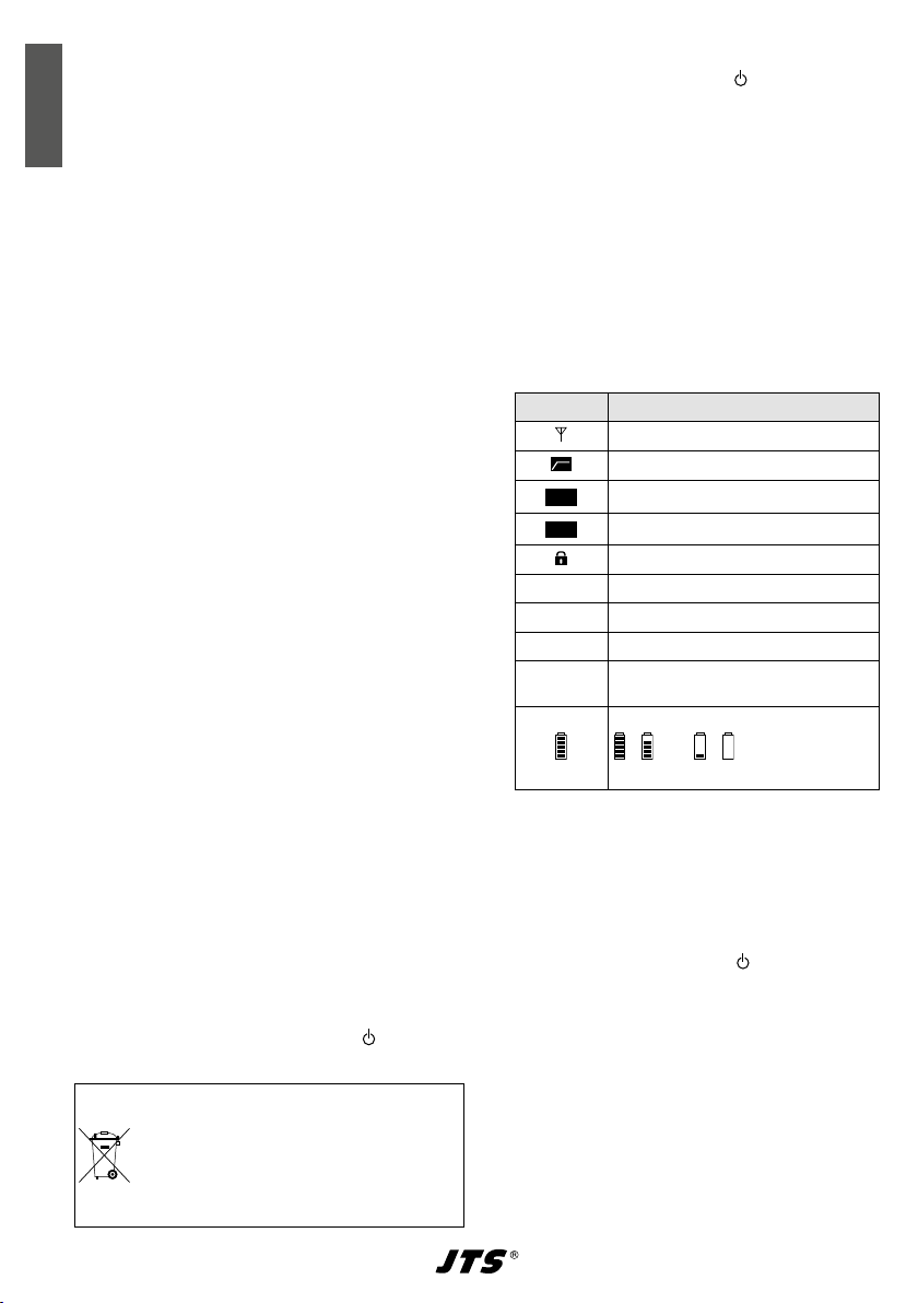
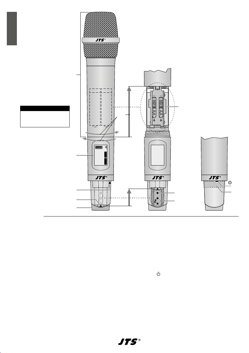
Übersicht
1 oberes Mikrofonteil mit Batteriefach; zum Öff-
nen das obere und untere Mikrofonteil mit
jeweils einer Hand festhalten und auseinanderschrauben
2 Display, Details siehe Kap. 3.3, Abb. 3
3
Kontroll-LED:
leuchtet grün = Mikrofon eingeschaltet
blinkt rot = Mikrofon stummgeschaltet
leuchtet rot = Batterien verbraucht
leuchtet blau = über die REMOSET-Funktion
werden Einstellungen vom Empfänger zum
Mikrofon übertragen
4
Schieberiegel zum Schutz der Bedientasten
SET(7), und (8)
5
Kappe zur Kennzeichnung verschiedener
Mikrofone: Die Kappe lässt sich gegen eine der
beiliegenden Farbkappen austauschen
1. 2.
6
SET
7
8
6 Batteriehalter, zum Wechseln der Batterien den
Halter hochklappen
7
Taste SET zum Aufrufen des Einstellmenüs
Abb. 1 (Taste 2 s lang gedrückt halten, bis das
Menü im Display erscheint). Zum Aufrufen eines
Menüpunktes und zum Speichern einer Einstellung siehe Kap. 3.4.
8 Tasten und zum Anwählen eines Menü-
punktes und zum Ändern von Einstellungen
9 Taste zum Ein-/Ausschalten, Stummschalten
und Verlassen des Menüs/eines Menüpunkts
– Einschalten, Mikrofon stumm/nicht stumm
oder Menü(punkt) verlassen: Taste kurz drücken
– Ausschalten: Taste 2 Sek. lang gedrückt halten,
bis das Display Power OFF anzeigt.
10
beiliegender Farbring zum Aufsetzen
(siehe auch Position 5)
9
4
Page 5

Funkmikrofon
Diese Anleitung richtet sich an Bediener ohne
besondere Fachkenntnisse. Bitte lesen Sie die
Anleitung vor dem Betrieb gründlich durch und
heben Sie sie für ein späteres Nachlesen auf.
Inhalt
1 Wichtige Hinweise fürdenGebrauch. . . . . 5
2 Einsatzmöglichkeiten . . . . . . . . . . . . 5
2.1 Konformität und Zulassung. . . . . . . . . . 5
3 Inbetriebnahme . . . . . . . . . . . . . . 6
3.1 Batterien einsetzen oder wechseln. . . . . . . 6
3.2 Betrieb mit Akkus . . . . . . . . . . . . . . 6
3.3 Mikrofon ein- und ausschalten . . . . . . . . 6
3.4 Einstellungen über das Menü . . . . . . . . . 6
3.5 Grundeinstellungen und Reset . . . . . . . . 7
3.6 Übertragungsfrequenz einstellen . . . . . . . 7
3.6.1 REMOSET-Funktion . . . . . . . . . . . . 8
3.6.2 Frequenz manuell einstellen. . . . . . . . . 8
3.6.3 Frequenz aus einer Gruppe wählen . . . . . 9
3.7 Sendeleistung einstellen . . . . . . . . . . . 9
3.8 Mikrofonempfindlichkeit einstellen . . . . . . 9
3.9 Low-Cut-Filter . . . . . . . . . . . . . . . 9
3.10 Mikrofon stummschalten. . . . . . . . . . . 9
3.11 Tastensperre . . . . . . . . . . . . . . . 10
4 Technische Daten . . . . . . . . . . . . 11
Übertragungsfrequenzen. . . . . . . . . . . . .38
1 Wichtige Hinweise
fürdenGebrauch
Das Mikrofon entspricht allen relevanten Richtlinien der EU und trägt deshalb das -Zeichen.
Das
Mikrofon
•
nenbereich geeignet. Schützen Sie es vor Tropfund Spritzwasser, hoher Luftfeuchtigkeit, Hitze
und Kälte (zulässiger Einsatztemperaturbereich
0 – 40 °C).
Verwenden Sie für die Reinigung nur ein tro-
•
ckenes, weiches Tuch, niemals Wasser oder
Chemikalien.
Wird das Mikrofon zweckentfremdet, falsch
•
bedient oder nicht fachgerecht repariert, kann
ist nur zur Verwendung im In-
keine Haftung für daraus resultierende Sachoder Personenschäden und keine Garantie für
das Mikrofon übernommen werden.
Soll das Mikrofon endgültig aus dem
Betrieb genommen werden, übergeben
Sie es zur umweltgerechten Entsorgung
einem örtlichen Recyclingbetrieb.
2 Einsatzmöglichkeiten
Dieses dynamische Handmikrofon mit integriertem UHF-Sender bildet mit dem Empfänger
UF-20R /5 oder UF-20S/5 von JTS ein drahtloses
Audio-Übertragungssystem. Zum Lieferumfang
gehören ein Mikrofonkoffer, ein Mikrofonhalter,
aufsteckbare Farbkappen und Farbringe zur Kennzeichnung des Mikrofons.
Besonders komfortabel ist die Bedienung des
Systems durch die REMOSET®-Funktion. Damit
wird per Knopfdruck über ein 2,4-GHz-Funksignal
das Mikrofon z. B. auf die am Empfänger gewählte
Übertragungsfrequenz eingestellt.
2.1 Konformität und Zulassung
Hiermit erklärt MONACOR INTERNATIONAL,
dass das Funkmikrofon JSS-20/5 der Richtlinie
2014/53/EU entspricht. Die EU-Konformitätserklärung ist im Internet verfügbar:
www.jts-germany.de oder www.monacor.com
Dieses Funkmikrofon darf in folgenden Ländern
betrieben werden:
DE
Das Funkmikrofon muss im Gebiet der Bundes-
republik Deutschland eine Frequenzzuteilung
(kostenpflichtig) erhalten. Die Formulare und
Hinweise zur Anmeldung finden Sie im Internet
auf der Seite der Bundesnetzagentur:
www.bundesnetzagentur.de
In anderen Ländern muss eine entsprechende
Ge nehmigung beantragt werden. Informieren Sie
sich bitte vor der Inbetriebnahme des Mikrofons
außerhalb Deutschlands bei der MONACOR-Niederlassung oder der entsprechenden Behörde
des Landes. Links zu den nationalen Behörden
finden Sie über die folgende Internetadresse:
Deutsch
5
Page 6
www.cept.org
ECC
Topics/Info
SRD* Regulations and indicative list of equip-
Deutsch
ment sub-classes
EFIS and National Frequency Tables
*Short Range Devices (Geräte mit geringer Reichweite)
3 Inbetriebnahme
3.1 Batterien einsetzen oder wechseln
Für die Stromversorgung werden zwei 1,5-V-Batterien der Größe Mignon (A A) benötigt. Leuchtet
die LED (3) rot, sind die Batterien verbraucht und
sollten gewechselt werden.
Setzen Sie nur Batterien des gleichen Typs ein
•
und tauschen Sie sie immer zusammen aus.
Nehmen Sie bei längerem Nichtgebrauch die
•
Batterien sicherheitshalber heraus. So bleibt
das Mikrofon bei einem eventuellen Auslaufen
der Batterien unbeschädigt.
1) Das oberes Mikrofonteil (1) und das untere
jeweils mit einer Hand festhalten und auseinanderschrauben.
2) Den Batteriehalter (6) hochklappen.
3) Die Batterien, mit den Plus- und Minuspolen
wie auf dem Halter aufgedruckt, einsetzen.
4) Den Batteriehalter herunterklappen und das
Mikrofonoberteil und das Unterteil wieder zusammenschrauben.
3.2 Betrieb mit Akkus
Anstelle von Batterien können auch zwei
NiMH-Akkus (Nickel-Metallhydrid) der Größe
AA eingesetzt werden. Zum Aufladen der Akkus
eignet sich optimal die Ladestation CH-2: Die
Akkus können im Mikrofon verbleiben. Das
Mikrofon einfach in einen Ladeschacht stecken.
Über die Kontakte neben der Taste (9) erfolgt
die Stromzufuhr.
Verbrauchte Batterien und defekte Akkus
dürfen nicht in den Hausmüll geworfen
werden. Geben Sie sie zur umweltgerechten Entsorgung nur in den Sondermüll (z. B. Sammelbehälter bei Ihrem
Fachhändler).
3.3 Mikrofon ein- und ausschalten
1) Das Mikrofon mit der Taste (9) einschalten.
Die LED (3) leuchtet grün und die Hintergrundbeleuchtung des Displays (2) leuchtet
einige Sekunden lang. Beim Betätigen einer
Taste (7, 8, 9) schaltet die Beleuchtung erneut ein.
Leuchtet die LED (3) rot und zeigt das
Display periodisch die Meldung
Low, sind die Batterien verbraucht. Blinkt die
Battery
LED rot und erscheint periodisch die Meldung
Mute ON, ist das Mikrofon stummgeschaltet
(Kap. 3.10).
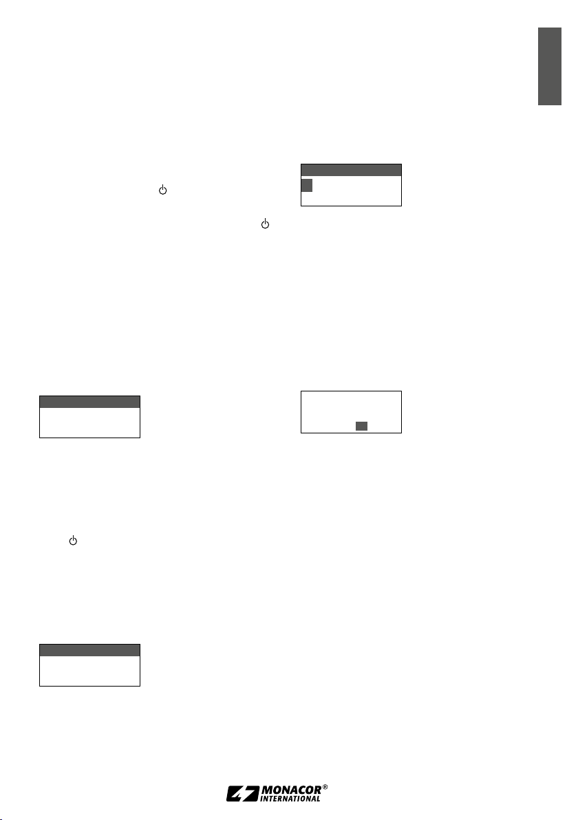
2) Das Display zeigt folgende Informationen an:
Zeichen Bedeutung
Sendeleistung Hi (hoch) / Lo (niedrig)
Low-Cut-Filter eingeschaltet
eingestellte Mikrofonempfindlichkeit
dB
Identifikations-Nr.
ID
Tastensperre aktiviert
JSS-20
MHz
Abb. 3 Informationen im Display
3)
Die Kappe (5) zur Kennzeichnung ver-
Gerätename, frei editierbar (10 Zeichen)
Gruppennummer (1 … 15)
G
Kanalnummer (1 … 63)
C
Übertragungsfrequenz
(530,000 … 605,000 MHz)
Batteriezustand
…
voll entladen
schiedener Mikrofone lässt sich abnehmen
und gegen eine der beiliegenden Farbkappen austauschen. Zusätzlich kann auch
einer der Farbringe (10) aufgesetzt werden.
4) Zum Ausschalten die Taste 2 Sek. gedrückt
halten, bis das Display Power OFF anzeigt.
3.4 Einstellungen über das Menü
Alle Einstellungen erfolgen über ein Menü:
1) Zum Aufrufen des Hauptmenüs (Abb. 1) die
Taste SET (7) zwei Sekunden gedrückt halten,
bis das Menü im Display (2) erscheint.
2) Den gewünschten Menüpunkt mit der Taste
oder (8) anwählen und mit der Taste
SET den Menüpunkt aufrufen.
6
Page 7
3) Die Einstellung mit der Taste oder vornehmen.
4) Sind bei einem Menüpunkt mehrere Einstellfunktionen vorhanden (z. B. Gruppen- und
Kanalnummer), mit der Taste SET von einer
Funktion zur nächsten weiterspringen.
5)
Zum Speichern einer Einstellung die Taste SET
drücken. Das Display zeigt kurz Saving an,
dann erscheint wieder das Hauptmenü.
Um einen Menüpunkt ohne Änderung
zu verlassen, die Taste (9) drücken. Es erscheint wieder das Hauptmenü.
6) Zum Verlassen des Hauptmenüs die Taste
drücken oder den Menüpunkt Exit mit der
Taste oder anwählen und die Taste SET
drücken.
Alle Einstellmöglichkeiten über das Menü sind in
den folgenden Kapiteln beschrieben.
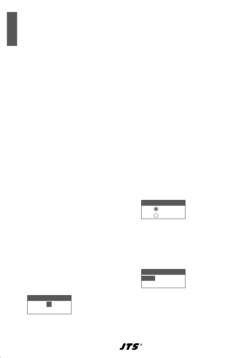
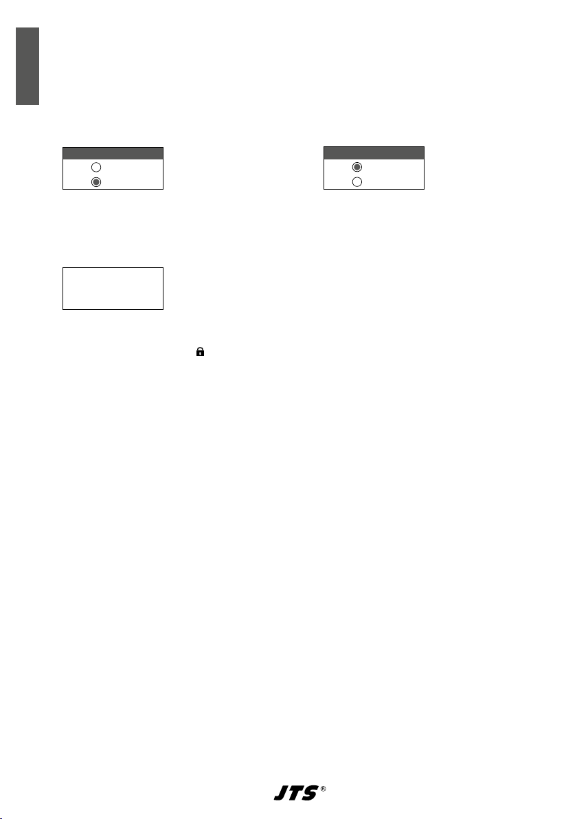
3.5 Grundeinstellungen und Reset
1)
Lässt sich das Display nicht gut ablesen, zur Kontrast einstellung den Menüpunkt 8. Contrast aufrufen:
LCD Contrast
10
Abb. 4
Den Kontrast mit der Taste oder einstellen. Das Display zeigt den eingestellten
Wert zwischen 0 und 20 an. Die Einstellung
mit der Taste SET speichern. Das Hauptmenü
erscheint wieder.
Zum Ausblenden des Hauptmenüs die
Taste drücken oder zum Ändern einer anderen Einstellung den entsprechenden Menüpunkt mit der Taste oder anwählen und
die Taste SET drücken.
2)
Die Dauer der Displaybeleuchtung lässt sich
über den Menüpunkt 9. Light Time einstellen:
Light Time
15 Sec.
Abb. 5
Always OFF = keine Beleuchtung
5 – 30 Sec. = Zeit in Sekunden
Always ON = ständige Beleuchtung
Tipp: Um die Batterien zu schonen, sollte Always
nicht als ständige Einstellung gewählt werden.
ON
3)
Über den Menüpunkt a. User Name
lässt sich ein Gerätename eingeben (max.
10Zeichen), der im Display erscheint, wie
in der Abb. 2 als Beispiel der Name JSS-20.
Bei dem Betrieb mit mehreren Mikrofonen
können so die Mikrofone leicht unterschieden
und zugeordnet werden. Nach dem Aufrufen
des Menüpunkts
a. User Name
ist die erste
Zeichenstelle angewählt.
User Name
J SS-20
Char:1/10
Abb. 6
Das gewünschte Zeichen mit der Taste
oder auswählen. Mit der Taste SET auf die
nächste Zeichenstelle springen. Nach dem
Einstellen des Namens die Taste SET so oft
drücken, bis das Display
Saving
anzeigt.
Danach erscheint wieder das Hauptmenü.
4)
Zum Zurückstellen auf die Werkseinstellung
(Reset) den Menüpunkt c. Reset anwäh-
len und die Taste SET drücken. Es erscheint
der Hinweis, dass alle gespeicherten Daten
gelöscht werden:
This will erase
all data from Mic
Internal Storage.
Yes/No
Abb. 7
Zum Abbrechen des Vorgangs die Auswahl No
belassen und die Taste SET drücken oder zum
Rücksetzen mit der Taste Yes anwählen
und die Taste SET drücken.
3.6 Übertragungsfrequenz einstellen
Das Mikrofon noch ausgeschaltet lassen. Zuerst
den Empfänger auf eine störungsfreie Frequenz
einstellen, siehe Bedienungsanleitung des Empfängers. Dann das Mikrofon auf dieselbe Frequenz einstellen. Dazu gibt es drei Möglichkeiten:
1. Wird das Mikrofon mit dem Empfänger UF20R /5 oder UF-20S/5 betrieben, ist es am einfachsten die patentierte REMOSET-Funktion zu
nutzen. Durch Drücken der Taste REMOSET am
Empfänger stellt sich das Mikrofon auf die am
Empfänger gewählte Übertragungsfrequenz
ein (Kap. 3.6.1).
2. Die Übertragungsfrequenz lässt sich zwischen
530,000 MHz und 605,000 MHz manuell einstellen (Kap. 3.6.2).
Deutsch
7
Page 8
3. Für den Betrieb von mehreren Audio-Übertragungssystemen gleichzeitig sind in 15Gruppen bis zu 63 Kanäle pro Gruppe zusammengestellt (siehe Tabelle ab Seite 38).
Unter optimalen Bedingungen können aus
Deutsch
einer Gruppe alle Kanäle gleichzeitig für die
Audio-Übertragungen genutzt werden. Wurde
der Empfänger auf einen Kanal aus diesen
Gruppen eingestellt, denselben Kanal für das
Mikrofon auswählen (Kap. 3.6.3).
3.6.1 REMOSET-Funktion
Für die REMOSET-Funktion müssen folgende Bedingungen erfüllt sein:
1. Weder am Mikrofon noch am Empfänger darf
ein Menü aufgerufen sein.
2. Das Mikrofon muss eingeschaltet sein und sich
in der Nähe des Empfängers befinden (Reichweite der REMOSET-Übertragung ca. 10 m).
3. Das Mikrofon muss auf dieselbe Identifikationsnummer (ID-Nr.) wie der Empfänger eingestellt sein oder die Funktion ID-Nr. muss
ausgeschaltet sein (siehe Absatz „Identifikationsnummer“).
4. Die REMOSET-Funktion darf nicht gesperrt sein
(siehe Absatz „REMOSET-Funktion sperren“).
5. Der Empfänger und das Mikrofon dürfen nicht
gesperrt sein (Kap. 3.11).
6. Das Mikrofon darf nicht stummgeschaltet sein
(Kap. 3.10).
– Identifikationsnummer –
Jedem Mikrofon / Empfänger-Paar muss eine andere Identifikationsnummer (ID-Nr.) zugewiesen
werden, damit sich die einzelnen Paare bei der
REMOSET-Übertragung nicht gegenseitig beeinflussen. Wird nur ein Mikrofon / Empfänger-Paar
verwendet, kann die voreingestellte ID-Nr. 1 beibehalten werden. Zum Ändern der ID-Nr.:
1)
Über den Menüpunkt 5. Device ID des
Hauptmenüs die Einstellung für die ID-Nr.
aufrufen.
Device ID
1
ID : ON
Abb. 8
2) Die ID-Nr. mit der Taste oder einstellen.
3) Die Taste SET drücken. Jetzt mit der Taste
die Funktion ausschalten (OFF) oder mit der
Taste einschalten (ON). Bei ausgeschalteter
Funktion kann die REMOSET-Übertragung von
jedem Empfänger UF-20R /5 und UF-20S/5
erfolgen, bei eingeschalteter Funktion nur vom
einem Empfänger mit derselben ID-Nr.
4) Die Einstellung mit der Taste SET speichern.
– REMOSET-Übertragung –
Am Empfänger die Taste REMOSET drücken. Sobald das Mikrofon auf die Übertragungsfrequenz
bzw. auf die Gruppe und den Übertragungskanal des Empfängers eingestellt ist, leuchtet die
LED(3) fünf Sekunden lang blau und das Display
zeigt Sync...
Leuchtet die LED nicht blau auf, konnte das
Mikrofon nicht automatisch eingestellt werden.
Am Empfänger blinkt dann die Taste REMOSET
langsam. Zur möglichen Fehlerursache siehe die
Punkte 1. – 6. am Anfang des Kapitels. Die Einstellungen am Mikrofon und eventuell am Empfänger überprüfen und korrigieren. Dann die Taste
REMOSET des Empfängers erneut betätigen.
– REMOSET-Funktion sperren –
Um eine automatische Einstellung zu verhindern,
lässt sich die REMOSET-Funktion sperren.
1) Im Hauptmenü den Menüpunkt 6. Remo-
set aufrufen.
Remoset
ON
OFF
Abb. 9
2) Die Funktion mit der Taste sperren (OFF)
oder mit der Taste einschalten (ON).
3) Die Einstellung mit der Taste SET speichern.
3.6.2 Frequenz manuell einstellen
1)
Über den Menüpunkt 1. Frequency des
Hauptmenüs die Frequenzeinstellung aufrufen.
Frequency
532.625
G: 1 C: 1
2)
Die Frequenz mit der Taste oder in
Abb. 10
1-MHz-Schritten einstellen.
3)
Die Taste SET drücken, sodass die Ziffern nach
dem Punkt (= Komma) markiert sind. Eine
Feineinstellung in 0,025-MHz-Schritten mit
der Taste oder vornehmen. Ist die Frequenz identisch mit der eines Kanals in einer
8
Page 9
Gruppe, wird die Gruppen- und Kanalnummer
in der unteren Zeile angezeigt.
4)
Zum Speichern der eingestellten Frequenz die
Taste SET ein zweites Mal drücken.
3.6.3 Frequenz aus einer Gruppe wählen
1)
Über den Menüpunkt
2. Group/Channel
des Hauptmenüs die Gruppen- und Kanalauswahl aufrufen.
Group/Channel
G: 2 C: 1
530.375 MHz
2)
Die Gruppe mit der Taste oder aus-
Abb. 11
wählen.
3) Die Taste SET drücken, sodass die Kanalzahl
markiert ist. Dann mit der Taste oder
den Kanal auswählen. Die zugehörige Übertragungsfrequenz wird in der unteren Zeile
angezeigt.
4) Die Einstellung mit der Taste SET speichern.
3.7 Sendeleistung einstellen
1) Den Menüpunkt 7. RF Power aufrufen.
RF Power
High
Low
Abb. 12
2) Mit der Taste die Einstellung Low oder
mit der Taste die Einstellung
High
wäh-
len.
High
= hohe Leistung (50 mW) für eine
große Reichweite, jedoch kürzere
Betriebsdauer der Batterien
Low
= geringe Leistung (10 mW) für eine
längere Betriebsdauer, jedoch
dafür kürzere Reichweite
3)
Die Einstellung mit der Taste SET speichern.
2)
Die Empfindlichkeit nach der Anzeige AF
des Empfängers so einstellen, dass ein
optimaler Signalpegel erreicht wird. Bei
zu hoher Empfindlichkeit verzerrt das
Mikrofonsignal, dann mit der Taste einen
niedrigeren Wert einstellen (min. −15 dB).
Bei zu geringer Lautstärke ergibt sich ein
schlechter Rauschabstand, dann mit der
Taste einen höheren Wert einstellen
(max. +15 dB).
3) Die Einstellung mit der Taste SET speichern.
Hinweis: Die Einstellung Sensitivity lässt sich
auch direkt an den Empfängern UF-20R /5 und UF20S/5 über die REMOSET-Funktion vornehmen, siehe
Bedienungsanleitung der Empfänger.
3.9 Low-Cut-Filter
Um tiefe Frequenzen zu unterdrücken (z. B.
Trittschall, Rumpelgeräusche) lässt sich ein
Low-Cut-Filter (100 Hz, 18 dB/Oktave) einschalten.
1) Den Menüpunkt 4. Low Cut aufrufen.
LOW CUT
ON
2)
Das Filter mit der Taste einschalten (ON,
Abb. 14
Symbol ) oder mit der Taste ausschalten (OFF, Symbol ).
3)
Die Einstellung mit der Taste SET speichern.
Hinweise:
1. Bei ausgeblendetem Menü erscheint im Display bei
der Einstellung
bol .
2. Die Einstellung
den Empfängern UF-20R /5 und UF-20S/5 über die
REMOSET-Funktion vornehmen, siehe Bedienungs-
anleitung der Empfänger.
Low Cut ON
Low Cut
zur Kontrolle das Sym-
lässt sich auch direkt an
Deutsch
3.8 Mikrofonempfindlichkeit
einstellen
Mit der Einstellung der Empfindlichkeit wird das
Mikrofon an die Lautstärke der Stimme oder des
Instruments angepasst.
1)
Den Menüpunkt
3.
Sensitivity
auf-
rufen.
Sensitivity
0 dB
Abb. 13
3.10 Mikrofon stummschalten
Um das Mikrofon für kurze Zeit stummzuschalten,
z. B. in Sprech- oder Gesangspausen, die Taste
(9) kurz drücken. Die LED (3) blinkt dann rot
und das Display signalisiert periodisch
Das Display des Empfängers UF-20R /5 oder UF20S/5 leuchtet rot und es erscheint periodisch
die Meldung Mic. Mute. Zum Wiedereinschalten des Tons die Taste erneut drücken.
Hinweis: Wenn die Tastensperre aktiviert ist (Kap. 3.11),
ist auch die Mute-Funktion gesperrt.
Mute ON
.
9
Page 10
3.11 Tastensperre
Zum Schutz gegen ein versehentliches Ausschalten und Verstellen des Mikrofons kann eine Tastensperre aktiviert werden.
Deutsch
– Sperre aktivieren –
1)
Über den Menüpunkt d. KeyLock die
Sperrfunktion aufrufen.
KeyLock
ON
OFF
2)
Die Sperre mit der Taste einschalten (ON).
3) Die Einstellung mit der Taste SET speichern.
Wird jetzt eine Taste gedrückt, erscheint die Mel-
dung:
Press Set for
2 Sec. to
unlock keypad.
Hinweise:
1. Bei aktivierter Sperre und ausgeblendetem Menü erscheint im Display das Symbol .
2. Die Tastensperre lässt sich auch direkt an den Empfängern UF-20R /5 und UF-20S/5 über die REMO-
SET
-Funktion ein- und ausschalten, siehe Bedienungs-
anleitung der Empfänger.
Abb. 15
Abb. 16
– Sperre deaktivieren –
1)
Die Taste SET zwei Sekunden gedrückt halten,
bis das Menü KeyLock erscheint.
KeyLock
ON
OFF
2)
Die Einstellung
Abb. 17
OFF
mit der Taste anwählen
und mit der Taste SET speichern.
10
Page 11

4 Technische Daten
Mikrofontyp: . . . . . . . . . dynamisches
Hand mikrofon
Richtcharakteristik: . . . . Niere
Trägerfrequenzbereich:
Frequenzstabilität: . . . . . ±0,005 %
Sendeleistung (EIRP)
Low: . . . . . . . . . . . . . . 10 mW
High: . . . . . . . . . . . . . . 50 mW
REMOSET-Frequenz: . . . 2,4 GHz
Audiofrequenzbereich: . 50 – 18 000 Hz
Low-Cut-Filter: . . . . . . . . 100 Hz, 18 dB/Oktave
Einsatztemperatur: . . . . 0 – 40 °C
Stromversorgung: . . . . . 2 Batterien /Akkus der
Betriebsdauer:
Abmessungen: . . . . . . . ∅ 50 mm × 260 mm
Gewicht: . . . . . . . . . . . . 340 g
Änderungen vorbehalten.
. . . . . . . . > 20 h mit
. 530 – 605 MHz
Größe Mignon (AA)
3400-mAh-Akkus
Deutsch
Diese Bedienungsanleitung ist urheberrechtlich für MONACOR ® INTERNATIONAL GmbH & Co. KG geschützt.
Eine Reproduktion für eigene kommerzielle Zwecke – auch auszugsweise – ist untersagt.
11
Page 12
10
English
Fig. 1 Menu
Fig. 2 JSS-20/5
1
Ni-MHNi-MH
1. Frequency
2. Group/Channel
3. Sensitivity
4. Low Cut
5. Device ID
6. Remoset
7. RF Power
8. Contrast
9. Light Time
a. User Name
c. Reset
d. KeyLock
e. Exit
2
Lo
JSS-20
G:2 C:1
530.375 MHz
0dB ID1
LED
3
4
5
Overview
1 Top part of microphone with battery compart-
ment; seize the top part with one hand and the
lower part with the other hand and unscrew the
top from the bottom
2 Display, for details refer to chapter 3.3, Fig. 3
3
Indicating LED:
lighting in green = microphone switched on
flashing in red = microphone muted
lighting in red = batteries discharged
lighting in blue = settings are being transferred
from the receiver to the microphone via the
REMOSET function
4
Sliding cover to protect the control buttons
SET(7), and (8)
5 Cap to distinguish different microphones: The
cap can be replaced by one the colour-coded
ID caps supplied.
1. 2.
6
SET
7
8
6 Battery holder; to replace the batteries, fold up
the holder
7 Button SET to call up the setup menu in Fig. 1
(keep the button pressed for 2 seconds until the
menu appears on the display). To call up a menu
item and to save a setting, refer to chapter 3.4.
8 Arrow buttons and to select a menu item
and to change settings
9 Button to switch on/off, to mute the micro-
phone and to exit a menu/menu item
– To switch on, to mute/unmute the micro-
phone or to exit a menu (item), press the
button briefly.
– To switch off, keep the button pressed for
2seconds until the display indicates
OFF.
10
Colour-coded ID ring supplied
(also refer to item 5)
Power
9
12
Page 13

Wireless Microphone
These instructions are intended for users without
any specific technical knowledge. Please read the
instructions carefully prior to operation and keep
them for later reference.
Contents
1 Important Notes . . . . . . . . . . . . . 13
2 Applications . . . . . . . . . . . . . . . 13
2.1 Conformity and approval. . . . . . . . . . 13
3 Operation . . . . . . . . . . . . . . . . 14
3.1 Inserting or replacing the batteries. . . . . . 14
3.2 Operation with rechargeablebatteries . . . . 14
3.3 Switching the microphone on or off . . . . . 14
3.4 Settings via the menu . . . . . . . . . . . 14
3.5 Basic settings and reset . . . . . . . . . . 15
3.6 Setting the transmission frequency . . . . . 15
3.6.1 REMOSET function. . . . . . . . . . . . 16
3.6.2 Setting the frequency manually . . . . . . 16
3.6.3 Selecting a frequency from a group . . . . 17
3.7 Adjusting the transmission power . . . . . . 17
3.8 Adjusting the microphonesensitivity . . . . . 17
3.9 Low-cut filter . . . . . . . . . . . . . . . 17
3.10 Muting the microphone . . . . . . . . . . 17
3.11 Key lock . . . . . . . . . . . . . . . . . 18
4 Specifications . . . . . . . . . . . . . . 19
Transmission frequencies . . . . . . . . . . . . 38
1 Important Notes
The microphone corresponds to all relevant directives of the EU and is therefore marked with .
The microphone is suitable for indoor use only.
•
Protect it against dripping water and splash
water, high air humidity and heat (admissible
ambient temperature range: 0 – 40 °C).
For cleaning only use a dry, soft cloth; never
•
use water or chemicals.
No guarantee claims for the microphone and
•
no liability for any resulting personal damage or
material damage will be accepted if the microphone is used for other purposes than originally
intended, if it is not correctly operated, or if it
is not repaired in an expert way.
If the microphone is to be put out of
operation definitively, take it to a local
recycling plant for a disposal which is not
harmful to the environment.
2 Applications
Combined with the JTS receiver UF-20R/5 or
UF-20S/5, this dynamic hand-held microphone
with integrated UHF transmitter creates a wireless
audio transmission system. The microphone is
supplied with a microphone case, a microphone
support, colour-coded ID caps and rings to identify the microphone.
The REMOSET® function is a most convenient
feature for operating the system: Simply press a
button and, via a 2.4 GHz radio signal, the microphone is matched to the transmission frequency
selected on the receiver.
2.1 Conformity and approval
Herewith, MONACOR INTERNATIONAL declare
that the wireless microphone JSS-20/5 complies
with the directive 2014/53/EU. The EU declaration of conformity is available on the Internet:
www.jts-germany.de or www.monacor.com
This wireless microphone may be operated in the
following countries:
DE
In the Federal Republic of Germany, the wireless
microphone requires a frequency assignment (for
which a fee is charged).
In other countries, it is necessary to apply for
a corresponding approval. Prior to operating the
microphone outside Germany, please contact
the MONACOR subsidiary or the corresponding
authorities of the respective country. Links to the
national authorities can be found via the following
Internet address:
www.cept.org
ECC
Topics/Info
SRD* Regulations and indicative list of equip-
ment sub-classes
EFIS and National Frequency Tables
*Short Range Devices
English
13
Page 14

3 Operation
3.1 Inserting or replacing the batteries
For power supply, two 1.5 V batteries of size AA
English
are required. If the LED (3) shows red, the batteries are discharged and should be replaced.
Only insert batteries of the same type and al-
•
ways replace both of them.
If the microphone is not in use for a longer
•
period of time, always remove the batteries as
a precaution to prevent damage due to battery
leakage.
1)
Seize the top part (1) of the microphone with
one hand and the bottom part with the other
hand to unscrew the top from the bottom.
2) Fold up the battery holder (6).
3) Insert the batteries with the positive and negative poles as indicated in the holder.
4)
Fold down the battery holder and reassemble the top part and the bottom part of the
microphone.
the display, the batteries are discharged. If the
LED keeps flashing in red and the message
Mute ON periodically appears, the micro-
phone is muted (chapter 3.10).
2) The display shows the following information:
Symbol Meaning
Transmission power Hi (high) / Lo (low)
Low-cut filter activated
Microphone sensitivity adjusted
dB
Identification number
ID
Key lock activated
JSS-20
MHz
Device name, to be edited as desired
(10 characters)
Group number (1 … 15)
G
Channel number (1 … 63)
C
Transmission frequency
(530.000 … 605.000 MHz)
Battery status
…
full discharged
3.2 Operation with
rechargeablebatteries
Instead of batteries it is also possible to insert
two rechargeable NiMH (nickel-metal hydrate)
batteries of size AA. To charge these batteries,
the charging station CH-2 is ideally suited: Leave
the batteries in the microphone and insert the
microphone into a charging slot. Power is supplied via the contacts next to the button (9).
Used batteries and defective rechargeable batteries must not be placed in the
household waste. To protect the environment, always take them to a special
waste disposal, e. g. collection container
at your retailer.
3.3 Switching the microphone on or off
1)
Press the button (9) to switch on the microphone. The LED (3) shows green and the
backlight of the display (2) lights up for a few
seconds. When you press a button (7, 8, 9),
the backlight is switched on again.
If the LED (3) shows red and the mes-
sage
Battery Low
periodically appears on
Fig. 3 Display information
3)
The cap (5) to distinguish different microphones can be removed and replaced by one
the colour-coded ID caps supplied. In addition,
one of the colour-coded rings (10) can be
pushed on.
4) To switch off, keep the button pressed for
2 s until the display indicates Power OFF.
3.4 Settings via the menu
All settings are made via a menu:
1) To call up the main menu (Fig. 1), keep the
button SET (7) pressed for two seconds until
the menu appears on the display (2).
2)
Press the button or (8) to select the
desired menu item. Then call up the menu
item with the button SET.
3)
To make the setting, press the button
or .
4) If multiple setup functions are available for a
menu item (e. g. group number and channel
number), press the button SET to go from one
function to the next one.
14
Page 15

5) To save a setting, press the button SET. The
display briefly indicates Saving before the
main menu reappears.
To exit a menu item without a change,
press the button (9). The main menu
reappears.
6) To exit the main menu, press the button or
press the button or to select the menu
item Exit and then press the button SET.
All setting options via the menu can be found in
the following chapters.
3.5 Basic settings and reset
1)
If it is difficult to read the display, call up
the contrast setting via the menu item
8. Contrast:
LCD Contrast
10
Fig. 4
Press the button or to set the contrast.
The display indicates the value adjusted
between 0 and 20. Press the button SET to
save the setting. The main menu reappears.
To deactivate the main menu, press the
button or to change another setting, press
the button or to select the corresponding
menu item and press the button SET.
2) To set the time for the display backlight, go
to the menu item 9. Light Time:
Light Time
15 Sec.
Fig. 5
Always OFF = no backlight
5 – 30 Sec. = time in seconds
Always ON = backlight always on
Hint: To save the batteries, it is advisable not to use
Always ON as a permanent setting.
3)
Via the menu item
a. User Name
name can be entered (10 characters max.)
which appears on the display (e. g. JSS-20
as shown in Fig. 2). When multiple microphones are used, this will make it easier to
distinguish between the microphones and to
identify them. After the menu item a. User
Name has been called up, the first character
position is selected:
, a device
User Name
J SS-20
Char:1/10
Fig. 6
Press the button or to select the desired character. Press the button SET to go
to the next character position. After setting
the name, press the button SET repeatedly
until the display indicates
Saving
. The main
menu reappears.
4) For a reset to the factory settings, select the
menu item c. Reset and press the button
SET. A message appears to warn you that resetting will erase any data stored:
This will erase
all data from Mic
Internal Storage.
Yes/No
Fig. 7
To cancel the process, retain the option No
and press the button SET; to reset, use the button to select
Yes
and press the button SET.
3.6 Setting the transmission frequency
Before switching on the microphone, set the
receiver to an interference-free frequency (refer
to the instruction manual of the receiver). Then
set the microphone to the same frequency: There
are three methods to do this:
1. If you operate the microphone together with
the receiver UF-20R/5 or UF-20S/5, the easiest way is to use the patented REMOSET
function. When you press the button REMOSET on the receiver, the microphone is set to
the transmission frequency selected on the
receiver (chapter 3.6.1).
2. The transmission frequency can be adjusted manually between 530.000 MHz and
605.000 MHz (chapter 3.6.2).
3. For operating multiple audio transmission systems at the same time, there are 15 groups
with up to 63 channels in each group (refer
to the table starting on page 38). In ideal
conditions, all channels from a group can be
used for audio transmission at the same time.
If the receiver has been set to a channel from
these groups, select the same channel for the
microphone (chapter 3.6.3).
English
15
Page 16

3.6.1 REMOSET function
For the REMOSET function always make sure that
1. no menu is called up on the microphone or
on the receiver.
English
2. the microphone is switched on and close to
the receiver (REMOSET transmission range:
approx. 10 m).
3. the microphone and the receiver are set to the
same identification number (ID No.) or that the
function ID No. is deactivated (see paragraph
“Identification number”).
4. the REMOSET function is not disabled (see
paragraph “Disabling the REMOSET function”).
5. the receiver and the microphone are not locked
(chapter 3.11).
6. the microphone is not muted (chapter 3.10).
– Identification number –
To prevent mutual interference of individual pairs
of microphone/receiver during REMOSET transmission, each pair must have a different identification number (ID No.). If you only use one
pair of microphone/receiver, there is no need to
change the preset ID No. 1. To change the ID No.:
1)
Call up the setting for the ID No. via the menu
item 5. Device ID of the main menu.
Device ID
1
ID : ON
Fig. 8
2) Press the button or to set the ID No.
3)
Press the button SET. Then press the button
to deactivate the function (OFF) or the button
to activate the function (ON). If the function
has been deactivated, the REMOSET transmission will be possible from any UF-20R/5 or
UF-20S/5 receiver; if the function has been activated, the REMOSET transmission will only be
possible from a receiver with the same ID No.
4) Press the button SET to save the setting.
– REMOSET transmission –
Press the button REMOSET on the receiver. As
soon as the microphone has been set to the
transmission frequency or to the group and the
transmission channel of the receiver, the LED(3)
shows blue for five seconds and the display indicates Sync...
If the LED does not show blue, the automatic
synchronization of the microphone has failed. In
this case, the button REMOSET on the receiver
keeps flashing slowly. For troubleshooting see
steps 1 – 6 at the beginning of this chapter. Check
the settings on the microphone and possibly on
the receiver and correct them. Then press the
button REMOSET on the receiver again.
– Disabling the REMOSET function –
The REMOSET function can be disabled to prevent automatic setting:
1) Call up the menu item 6. Remoset in the
main menu.
Remoset
ON
OFF
2)
Press the button to disable the func-
Fig. 9
tion(OFF) or the button to enable the
function (ON).
3) Press the button SET to save the setting.
3.6.2 Setting the frequency manually
1)
Call up the frequency setting via the menu
item 1. Frequency of the main menu.
Frequency
532.625
G: 1 C: 1
2)
Press the button or to set the frequency
Fig. 10
in steps of 1 MHz.
3)
Press the button SET so that the digits after the
decimal point are highlighted. To make a fine
adjustment in steps of 0.025 MHz, press the
button or . If the frequency is identical
to the frequency of a channel in a group, the
group and channel numbers are indicated in
the lower line.
4) Press the button SET a second time to save
the frequency selected.
16
Page 17

3.6.3 Selecting a frequency from a group
1) Call up the group and channel selections via
the menu item
2. Group/Channel
of the
main menu.
Group/Channel
G: 2 C: 1
530.375 MHz
Fig. 11
2) Press the button or to select the group.
3) Press the button SET to highlight the channel
number. Then press the button or to select the channel. The corresponding transmission frequency is indicated in the lower line.
4) Press the button SET to save the setting.
3.7 Adjusting the transmission power
1) Call up the menu item 7. RF Power.
RF Power
High
Low
2)
Press the button for the setting
Fig. 12
Low
or the
button for the setting High.
High
= high power (50 mW): high range, but
short battery life
Low = low power (10 mW): long battery life,
but short range
3) Press the button SET to save the setting.
3.8 Adjusting the
microphonesensitivity
The sensitivity adjustment is used to match the
microphone to the volume of the voice or the
instrument.
1) Call up the menu item 3. Sensitivity.
Sensitivity
0 dB
Fig. 13
2) Adjust the sensitivity according to the indication AF of the receiver in such a way that an
optimum signal level is obtained. If the sensitivity is too high, the microphone signal will
distort; in this case, press the button to set
a lower value (min. −15 dB). If the volume is
too low, there will be a poor signal-to-noise
ratio; in this case, press the button to set a
higher value (max. +15 dB).
3) Press the button SET to save the setting.
Note: The setting Sensitivity can also be made
directly on the receivers UF-20R/5 and UF-20S/5 via
the REMOSET function (refer to the instruction manual
of the receivers).
3.9 Low-cut filter
To suppress low frequencies (e. g. impact sound,
rumble), a low-cut filter (100 Hz, 18 dB/octave)
can be activated.
1) Call up the menu item 4. Low Cut.
LOW CUT
ON
Fig. 14
2) Press the button to activate the filter (ON,
symbol ) or press the button to deactivate the filter (OFF, symbol ).
3) Press the button SET to save the setting.
Notes:
1. In the setting Low Cut ON, when the menu is de-
activated, the symbol
an indication.
2. The setting Low Cut can also be made directly on
the receivers UF-20R/5 and UF-20S/5 via the REMOSET function (refer to the instruction manual of
the receivers).
appears on the display as
3.10 Muting the microphone
To briefly mute the microphone, e. g. in speech/
music pauses, briefly press the button (9).
The LED (3) keeps flashing in red and the display
periodically indicates Mute ON. The display of
the receiver UF-20R/5 or UF-20S/5 lights up in
red and the message
ically appears. To unmute, press the button
once again.
Note: When the keys are locked (chapter 3.11), the
muting function is locked as well.
Mic. Mute
period-
English
17
Page 18

3.11 Key lock
The microphone is provided with a key lock to
prevent inadvertent switch-off or operation.
English
– Activating the lock –
1) Call up the lock function via the menu item
d. KeyLock.
KeyLock
ON
OFF
Fig. 15
2) Press the button to activate the key lock
(ON).
3) Press the button SET to save the setting.
When a button is pressed, the following message
appears:
Press Set for
2 Sec. to
unlock keypad.
Notes:
1. When the key lock is activated and the menu is
deactivated, the symbol appears on the display.
2. The key lock can also be activated or deactivated di-
rectly on the receivers UF-20R/5 and UF-20S/5 via
the REMOSET function (refer to the instruction manual
of the receivers).
Fig. 16
– Deactivating the lock –
1)
Keep the button SET pressed for two seconds
until the menu KeyLock appears.
KeyLock
ON
OFF
Fig. 17
2) Press the button to select the setting OFF
and press the button SET to save the setting.
18
Page 19

4 Specifications
Type of microphone: . . dynamic hand-held
microphone
Pick-up characteristic: . . cardioid
Carrier frequency range:
Frequency stability: . . . . ±0.005 %
Transmission power (EIRP)
Low: . . . . . . . . . . . . . . 10 mW
High: . . . . . . . . . . . . . . 50 mW
REMOSET frequency: . . 2.4 GHz
Audio frequency range: 50 – 18 000 Hz
Low-cut filter: . . . . . . . . 100 Hz, 18 dB/octave
Ambient temperature: . 0 – 40 °C
Power supply: . . . . . . . . 2 (rech.) batteries
Operating time:
Dimensions : . . . . . . . . ∅ 50 mm × 260 mm
Weight: . . . . . . . . . . . . . 340 g
. . . . . . . > 20 h with 3400 mAh
Subject to technical modification.
530 – 605 MHz
of size AA
rech. batteries
English
All rights reserved by MONACOR ® INTERNATIONAL GmbH & Co. KG. No part of this instruction manual may be
reproduced in any form or by any means for any commercial use.
19
Page 20

10
Français
Schéma 1 Menu
Schéma 2 JSS-20/5
1
Ni-MHNi-MH
1. Frequency
2. Group/Channel
3. Sensitivity
4. Low Cut
5. Device ID
6. Remoset
7. RF Power
8. Contrast
9. Light Time
a. User Name
c. Reset
d. KeyLock
e. Exit
2
Lo
JSS-20
G:2 C:1
530.375 MHz
0dB ID1
LED
3
4
5
Vue d'ensemble
1 Partie supérieure du micro avec compartiment
batterie : pour ouvrir, tenez la partie inférieure
avec une main et la partie supérieure du micro
avec l'autre main et dévissez-les.
2 Affichage, détails voir chapitre 3.3, schéma 3
3
LED de contrôle:
brille en vert = micro allumé
clignote en rouge = son du micro coupé
brille en rouge = batteries déchargées
brille en bleu = les réglages du récepteur sont
transmis au micro via la fonction REMOSET
4 Couvercle à glissière pour protéger les touches
de commande SET (7), et (8)
5 Capuchon de repérage des différents micros:
le capuchon peut être remplacé par un des capuchons de couleur livrés
6 Support batterie : ouvrez-le pour remplacer les
batteries
6
1. 2.
SET
7
8
7 Touche SET pour appeler le menu de réglage,
schéma 1 (Maintenez la touche enfoncée pendant 2 secondes jusqu'à ce que le menu soit
visible sur l'affichage.) Pour appeler un point
de menu et pour mémoriser un réglage, voir
chapitre 3.4.
8 Touches et pour sélectionner un point de
menu et modifier les réglages
9 Touche pour allumer/éteindre, couper le son
et quitter le menu/un point de menu
– allumer, couper/réactiver le son du micro ou
quitter le menu (point de menu) : appuyez
brièvement sur la touche
– éteindre : maintenez la touche enfoncée pen-
dant 2 secondes jusqu'à ce que l'affichage
indique Power OFF.
10 Anneau de couleur de repérage livré (voir éga-
lement position 5)
9
20
Page 21

Microphone sans fil
Cette notice s'adresse aux utilisateurs sans
connaissances techniques particulières. Veuillez
lire la notice avec attention avant le fonctionnement et conservez-la pour pouvoir vous y reporter
ultérieurement.
Table des matières
1 Conseils importants d'utilisation . . . . . . 21
2 Possibilités d'utilisation . . . . . . . . . . 21
2.1 Conformité et autorisation . . . . . . . . . 21
3 Fonctionnement . . . . . . . . . . . . . 22
3.1 Insérer ou remplacer les batteries . . . . . . 22
3.2 Fonctionnement avec desaccumulateurs. . . 22
3.3 Allumer et éteindre le micro . . . . . . . . 22
3.4 Réglages via le menu . . . . . . . . . . . 22
3.5 Réglages de base et Reset . . . . . . . . . 23
3.6 Réglage de la fréquence detransmission . . . 23
3.6.1 Fonction REMOSET . . . . . . . . . . . 24
3.6.2 Réglage manuel de la fréquence . . . . . . 24
3.6.3 Sélection d'une fréquence dans ungroupe . 25
3.7 Réglage de la puissance d'émission . . . . . 25
3.8 Réglage de la sensibilité . . . . . . . . . . 25
3.9 Filtre Low Cut . . . . . . . . . . . . . . 25
3.10 Coupure du son du micro . . . . . . . . . 25
3.11 Verrouillage des touches . . . . . . . . . . 26
4 Caractéristiques techniques . . . . . . . . 27
Fréquences de transmission . . . . . . . . . . . 38
1 Conseils importants d'utilisation
Le microphone répond à toutes les directives
nécessaires de l’Union européenne et porte donc
le symbole .
Le microphone n’est conçu que pour une uti-
•
lisation en intérieur. Protégez-le de tout type
de projections d'eau, des éclaboussures, d'une
humidité de l'air élevée, du froid et de la chaleur (plage de température de fonctionnement
autorisée:
Pour le nettoyer, utilisez uniquement un chif-
•
fon sec et doux, en aucun cas de produits
chimiques ou d'eau.
Nous déclinons toute responsabilité en cas
•
0 – 40 °C
).
de dommages matériels ou corporels si le
microphone est utilisé dans un but autre que
celui pour lequel il a été conçu, s'il n'est pas
correctement utilisé ou n'est pas réparé par
un technicien habilité ; en outre, la garantie
deviendrait caduque.
Lorsque
retiré du service, vous devez le déposer
dans une usine de recyclage de proximité
pour contribuer à son élimination non polluante.
le microphone
CARTONS ET EMBALLAGE
PAPIER À TRIER
est définitivement
2 Possibilités d'utilisation
Ce microphone main dynamique avec émetteur UHF intégré, constitue, avec le récepteur
UF-20R/5 ou UF-20S/5 de JTS, un système de
transmission audio sans fil. Un coffret micro, une
pince micro, des capuchons de couleur et des
anneaux de couleur pour repérer le microphone
sont livrés.
L'utilisation du système est très agréable
grâce à la fonction REMOSET®. Par une simple
pression sur un bouton, le microphone se règle,
via un signal radio 2,4 GHz, sur la fréquence de
transmission réglée sur le récepteur.
2.1 Conformité et autorisation
Par la présente, MONACOR INTERNATIONAL déclare que
trouve en conformité avec la directive 2014/53/
UE. La déclaration UE de conformité est disponible
sur Internet :
www.jts-germany.de ou www.monacor.com.
Ce microphone sans fil peut fonctionner dans le
pays suivant :
DE
En Allemagne, le microphone doit recevoir une
attribution de fréquence (payante). Dans les
autres pays, une autorisation correspondante
doit être demandée. Avant la mise en service du
microphone en dehors de l’Allemagne, renseignez-vous auprès de la succursale MONACOR ou
des autorités nationales du pays correspondant.
Vous trouverez les liens permettant d'accéder
le microphone sans fil JSS-20/5
se
Français
21
Page 22

aux agences nationales compétentes à l'adresse
suivante :
www.cept.org
ECC
Français
Topics/Info
SRD* Regulations and indicative list of equip-
ment sub-classes
EFIS and National Frequency Tables
* Short Range Devices (appareils de faible portée)
3 Fonctionnement
3.1 Insérer ou remplacer les batteries
Deux batteries 1,5 V de type R6 sont nécessaires
pour l'alimentation. Si la LED (3) brille en rouge,
les batteries sont mortes et doivent être remplacées.
Insérez uniquement des batteries de même
•
type et remplacez-les toujours ensemble.
En cas de non-utilisation prolongée, retirez les
•
batteries par précaution, elles pourraient couler
et endommager le microphone.
1) Tenez la partie supérieure (1) du micro avec
une main et la partie inférieure avec l'autre
main et dévissez les deux parties.
2) Ouvrez le support de batterie (6).
3) Insérez les batteries en respectant les indications de polarité sur le support.
4)
Refermez le support de batterie et revissez
les parties supérieure et inférieure ensemble.
3.2 Fonctionnement avec
desaccumulateurs
A la place de batteries, vous pouvez utiliser deux
accumulateurs NiMH (nickel-hydrure métallique)
de type R6. Pour charger les accumulateurs, la
station de charge CH-2 est idéalement adaptée:
les accus peuvent rester dans le microphone.
Placez tout simplement le microphone dans un
compartiment de charge. L'alimentation s'effectue via les contacts à côté de la touche (9).
Ne jetez pas les batteries usagées et les
accumulateurs défectueux dans la poubelle domestique ; déposez-les dans un
container spécifique ou ramenez-les à
votre détaillant pour contribuer à leur
élimination non polluante.
3.3 Allumer et éteindre le micro
1) Allumez le microphone avec la touche (9).
La LED (3) brille en vert et le rétroéclairage
de l'affichage (2) brille pendant quelques
secondes. Lorsque vous activez une touche
(7, 8, 9), l'éclairage se rallume.
Si la LED (3) brille en rouge et si l'affichage
indique périodiquement le message
Low, les batteries sont déchargées. Si la LED
Battery
clignote en rouge et si le message Mute ON
s'affiche périodiquement, le son du micro et
coupé (chapitre
2)
L'affichage indique les informations suivantes:
Symbole Signification
dB
ID
JSS-20
G
C
MHz
Schéma 3 Informations sur l'affichage
3.10).
puissance émission Hi (élevée) / Lo (faible)
filtre Low Cut activé
sensibilité micro réglée
numéro identification
verrouillage touches activé
nom appareil, éditable (10 signes)
numéro groupe (1 … 15)
numéro canal (1 … 63)
fréquence transmission
(530,000 … 605,000 MHz)
état batterie
…
plein déchargé
3) Le capuchon (5) pour repérer les différents
micros peut être retiré et être remplacé par
un des capuchons de couleur livrés. On peut
également positionner un des anneaux de
couleur (10).
4) Pour éteindre, maintenez la touche enfoncée pendant 2 secondes jusqu'à ce que l'affichage indique
Power OFF.
3.4 Réglages via le menu
Tous les réglages s'effectuent via un menu :
1) Pour appeler le menu principal (schéma1),
maintenez la touche SET (7) enfoncée pendant 2 secondes jusqu'à ce que le menu soit
visible sur l'affichage (2).
2) Sélectionnez le point de menu souhaité avec
la touche ou (8) et appelez le point de
menu voulu avec la touche SET.
22
Page 23

3) Effectuez le réglage avec la touche ou .
4)
Si pour un point de menu, il y a plusieurs
réglages (par exemple numéro du groupe et
du canal), passez avec la touche SET d'une
fonction à une autre.
5)
Pour mémoriser un réglage, appuyez sur la
touche SET. L'affichage indique brièvement
Saving, puis le menu principal s'affiche.
Pour quitter un point de menu sans modification, appuyez sur la touche (9). Le menu
principal s’affiche à nouveau.
6) Pour quitter le menu principal, appuyez sur la
touche ou sélectionnez le point de menu
Exit avec la touche ou et appuyez sur
la touche SET.
Toutes les possibilités de réglage via le menu sont
décrites dans les chapitres suivants.
3.5 Réglages de base et Reset
1)
Si l'affichage n'est pas assez lisible, appelez, via
le point de menu 8. Contrast, le réglage
du contraste :
LCD Contrast
10
Schéma 4
Réglez le contraste avec la touche ou .
L'affichage indique la valeur réglée entre 0 et
20. Mémorisez le réglage avec la touche SET.
Le menu principal s'affiche à nouveau.
Pour désactiver le menu principal, appuyez
sur la touche ou pour modifier un autre
réglage, sélectionnez le point de menu correspondant avec la touche ou et appuyez
sur la touche SET.
2)
Il est possible de régler la durée d'éclai-
rage de l'affichage via le point de menu
9. Light Time:
Light Time
15 Sec.
Schéma 5
Always OFF = pas d'éclairage
5 – 30 Sec. = durée en secondes
Always ON = éclairage constant
Conseil : Pour économiser les batteries,
ON ne devrait pas être le réglage permanent.
3) Via le point de menu a. User Name, vous
pouvez saisir le nom de l'appareil (10 carac-
Always
tères maximum) qui est visible sur l'affichage,
comme sur le schéma 2 l'exemple du nom
JSS-20. Pendant le fonctionnement avec plusieurs microphones, on peut ainsi facilement
différencier les microphones et les identifier.
Lorsque le point de menu
a. User Name
est appelé, le premier emplacement de
caractère est sélectionné.
User Name
J SS-20
Char:1/10
Schéma 6
Sélectionnez le caractère voulu avec la touche
ou . Avec la touche SET, allez à l'emplacement suivant. Une fois le nom saisi, appuyez
sur la touche SET de manière répétée jusqu'à
ce que l'affichage indique
Saving
. Le menu
principal s'affiche ensuite.
4)
Pour revenir aux réglages d'usine (Reset),
sélectionnez le point de menu c. Reset et
appuyez sur la touche SET. Le message avertissant que toutes les données mémorisées
vont être écrasées, s'affiche :
This will erase
all data from Mic
Internal Storage.
Yes/No
Schéma 7
Pour interrompre le processus, sélectionnez
le choix No et appuyez sur la touche SET ou,
pour réinitialiser, sélectionnez Yes avec la
touche et appuyez sur la touche SET.
3.6 Réglage de la fréquence
detransmission
Laissez le microphone encore éteint. Réglez tout
d'abord le récepteur sur une fréquence sans interférence (voir notice d'utilisation du récepteur).
Réglez ensuite le microphone sur la même fréquence. Il y a trois possibilités :
1. Si le microphone est utilisé avec le récepteur
UF-20R/5 ou UF-20S/5, le plus simple est
d'utiliser la fonction REMOSET (déposée). En
appuyant sur la touche REMOSET sur le récepteur, le microphone se règle sur la fréquence
de transmission sélectionnée sur le récepteur
(voir chapitre 3.6.1).
2. Vous pouvez régler manuellement la fré-
quence de transmission entre 530,000 MHz
et 605,000 MHz (chapitre 3.6.2).
3. Pour le fonctionnement simultané de plu-
sieurs systèmes de transmission audio, jusqu'à
Français
23
Page 24

63canaux par groupe sont rassemblés en
15groupes (voir tableau à partir de la page
38). Dans des conditions optimales, on
peut utiliser simultanément tous les canaux
d'un groupe pour la transmission audio. Si
Français
le récepteur est réglé sur un canal de ces
groupes, sélectionnez le même canal pour le
microphone (chapitre 3.6.3).
3.6.1 Fonction REMOSET
Pour la fonction REMOSET, il faut remplir les
conditions suivantes :
1. Un menu ne doit pas être appelé ni sur le
microphone ni sur le récepteur.
2. Le microphone doit être allumé et être à proximité du récepteur (portée de la transmission
REMOSET : 10 m environ).
3. Le microphone doit être réglé sur le même numéro d'identification (ID No) que le récepteur
ou la fonction ID No doit être désactivée (voir
point «Numéro d'identification»).
4. La fonction REMOSET ne doit pas être verrouillée (voir point «Verrouillage de la fonction
REMOSET»).
5. Le récepteur ou le microphone ne doit pas
être verrouillé (chapitre 3.11).
6. Le son du microphone ne doit pas être coupé
(chapitre 3.10).
– Numéro d'identification –
Chaque paire microphone/récepteur doit recevoir
un autre numéro d'identification (ID No) pour
que les paires individuelles ne s’influencent pas
lors de la transmission REMOSET. Si seule une
paire microphone/récepteur est utilisée, on peut
conserver le préréglage ID No 1. Pour modifier le
numéro d'identification :
1)
Via le point de menu 5. Device ID du
menu principal, appelez le réglage pour le
numéro d'identification.
Device ID
1
ID : ON
2)
Réglez le numéro d'identification avec la
Schéma 8
touche ou .
3) Appuyez sur la touche SET. Maintenant, avec
la touche , désactivez la fonction (OFF)
ou avec la touche , activez-la (ON). Si
la fonction est désactivée, la transmission
REMOSET peut s'effectuer de chaque récepteur UF-20R /5 ou UF-20S/5 ; si la fonction est
activée, la transmission REMOSET n'est possible que depuis un récepteur avec le même
numéro d’identification.
4) Mémorisez le réglage avec la touche SET.
– Transmission REMOSET –
Sur le récepteur, appuyez sur la touche REMOSET. Dès que le microphone est réglé sur la fréquence de transmission ou le groupe et le canal
de transmission du récepteur, la LED (3) brille en
bleu pendant 5secondes et l'affichage indique
Sync...
Si la LED ne brille pas en bleu, le microphone
n'a pas pu être réglé automatiquement. Dans ce
cas, la touche REMOSET sur le récepteur clignote
lentement. En cas de problème, voir les points1
à 6 au début du chapitre. Vérifiez les réglages sur
le microphone et éventuellement sur le récepteur
et faites les corrections nécessaires. Ensuite, appuyez une nouvelle fois sur la touche REMOSET
du récepteur.
– Verrouillage de la fonction REMOSET –
Pour empêcher tout réglage automatique de fréquence, on peut verrouiller la fonction REMOSET.
1)
Sur le menu principal, appelez le point de
menu 6. Remoset.
Remoset
ON
OFF
2)
Avec la touche , désactivez la fonction (OFF)
Schéma 9
ou, avec la touche , activez-la (ON).
3) Mémorisez le réglage avec la touche SET.
3.6.2 Réglage manuel de la fréquence
1) Appelez le réglage de fréquence via le point
de menu
532.625
G: 1 C: 1
1. Frequency
Frequency
du menu principal.
Schéma 10
2) Réglez la fréquence par palier de 1 MHz avec
la touche ou .
3)
Appuyez sur la touche SET pour que les
chiffres après le point (= virgule) soient mis en
surbrillance. Effectuez un réglage précis avec
la touche ou par palier de 0,025 MHz.
24
Page 25

Si la fréquence est identique avec celle d'un
canal dans un groupe, le numéro du groupe
et du canal est indiqué sur la ligne inférieure.
4)
Pour mémoriser la fréquence réglée, appuyez
une seconde fois sur la touche SET.
3.6.3 Sélection d'une fréquence dans
ungroupe
1) Via le point de menu 2. Group/Channel
du menu principal, appelez la sélection de
groupe et de canal.
Group/Channel
G: 2 C: 1
530.375 MHz
2)
Sélectionnez le groupe avec la touche ou .
3)
Appuyez sur la touche SET pour que le numéro
Schéma 11
du canal soit repéré. Avec la touche ou ,
sélectionnez le canal. La fréquence de transmission correspondante est indiquée sur la ligne
inférieure.
4) Mémorisez le réglage avec la touche SET.
3.7 Réglage de la puissance d'émission
1) Appelez le point de menu 7. RF Power.
RF Power
High
Low
2)
Avec la touche , sélectionnez le réglage Low
Schéma 12
ou, avec la touche , le réglage High.
High = puissance élevée (50 mW) pour une
portée importante mais une durée
de vie des batteries plus courte
Low
=
puissance faible (10 mW) pour
une durée de vie des batteries plus
longue mais une portée plus courte
3) Mémorisez le réglage avec la touche SET.
3.8 Réglage de la sensibilité
Avec le réglage de sensibilité, vous pouvez adapter le microphone au volume de la voix ou de
l'instrument.
1)
Appelez le point de menu
vity.
Sensitivity
0 dB
Schéma 13
3. Sensiti-
2)
Réglez la sensibilité selon l'affichage AF du
récepteur pour atteindre un niveau de signal
optimal. Si la sensibilité est trop élevée, il y a
des distorsions sur le signal du micro, réglez
alors une valeur inférieure (minimum −15 dB)
avec la touche . Si le volume est trop faible,
on a un mauvais rapport signal sur bruit, réglez
alors une valeur plus élevée (+15 dB maximum) avec la touche .
3) Mémorisez le réglage avec la touche SET.
Conseil : Le réglage Sensitivity peut également
être directement effectué sur les récepteurs UF-20R /5
et UF-20S/5 via la fonction REMOSET, voir notice d'utilisation des récepteurs.
3.9 Filtre Low Cut
Pour éliminer les fréquences basses (par exemple
bruit de pas, rumble/bruit sourd), vous pouvez
activer un filtre Low Cut (100 Hz, 18 dB/octave).
1) Appelez le point de menu 4. Low Cut.
LOW CUT
ON
Schéma 14
2) Activez le filtre avec la touche (ON, symbole ) ou désactivez-le avec la touche
(OFF, symbole ).
3) Mémorisez le réglage avec la touche SET.
Remarques :
1. Dans le réglage Low Cut ON, si le menu est désac-
tivé, le symbole est visible sur l'affichage.
2. Le réglage
directement sur les récepteurs UF-20R/5 et UF-20S/5
via la fonction REMOSET, voir notice d'utilisation des
récepteurs.
Low Cut
peut également être effectué
3.10 Coupure du son du micro
Pour couper le son du micro pendant une courte
durée, par exemple pendant des pauses de discours ou de chant, appuyez brièvement sur la
touche (9). La LED (3) clignote alors en rouge,
l'affichage indique périodiquement
L'affichage du récepteur UF-20R/5 ou UF-20S/5
brille en rouge et le message
s'affiche périodiquement. Pour réactiver le son,
appuyez à nouveau sur la touche .
Remarque : Si le verrouillage des touches est activé
(chapitre 3.11), la fonction Mute est activée aussi.
Mute ON
Mic. Mute
Français
.
25
Page 26

3.11 Verrouillage des touches
Pour éviter que le microphone ne soit éteint ou
déréglé par inadvertance, on peut activer le verrouillage des touches.
Français
– Activer le verrouillage –
1)
Via le point de menu
fonction de verrouillage.
KeyLock
ON
OFF
2)
Activez (ON) le verrouillage avec la touche .
3) Mémorisez le réglage avec la touche SET.
Si maintenant vous appuyez sur une touche, le
message suivant s'affiche:
Press Set for
2 Sec. to
unlock keypad.
Remarques :
1. Lorsque le verrouillage est activé et le menu non affiché, le symbole est visible sur l'affichage.
2. Le verrouillage des touches peut également être activé
et désactivé directement sur les récepteurs UF-20R/5
et UF-20S/5 via la fonction REMOSET, voir notice des
récepteurs.
d. KeyLoc
Schéma 15
Schéma 16
, appelez la
– Désactiver le verrouillage –
1)
Maintenez la touche SET enfoncée pendant 2se-
condes jusqu'à ce que le menu
KeyLock
s'affiche.
KeyLock
ON
OFF
2)
Sélectionnez le réglage
Schéma 17
OFF
avec la touche
et mémorisez avec la touche SET.
26
Page 27

4 Caractéristiques techniques
Type microphone: . . . . . microphone main
dynamique
Directivité:
Plage fréquence
porteuse :
Stabilité fréquence : . . . ±0,005 %
Puissance émission (EIRP)
Low : . . . . . . . . . . . . . . 10 mW
High : . . . . . . . . . . . . . 50 mW
Fréquence REMOSET : . 2,4 GHz
Plage fréquence audio : 50 – 18 000 Hz
Filtre Low Cut : . . . . . . . 100 Hz, 18 dB/octave
Température fonc. : . . . 0 – 40 °C
Alimentation : . . . . . . . . 2 batteries/accus
Durée fonc. : . . . . . . . . . > 20 h avec accus
Dimensions : . . . . . . . . ∅ 50 mm × 260 mm
Poids : . . . . . . . . . . . . . . 340 g
Tout droit de modification réservé.
. . . . . . . . . . . cardiode
. . . . . . . . . . . 530 – 605 MHz
typeR6
3400 mAh
Français
Notice d’utilisation protégée par le copyright de MONACOR ® INTERNATIONAL GmbH & Co. KG. Toute reproduction
même partielle à des fins commerciales est interdite.
27
Page 28

10
Español
Fig. 1 Menú
Fig. 2 JSS-20/5
1
Ni-MHNi-MH
1. Frequency
2. Group/Channel
3. Sensitivity
4. Low Cut
5. Device ID
6. Remoset
7. RF Power
8. Contrast
9. Light Time
a. User Name
c. Reset
d. KeyLock
e. Exit
2
Lo
JSS-20
G:2 C:1
530.375 MHz
0dB ID1
LED
3
4
5
Vista General
1
Parte superior del micrófono con compartimento de la batería; sujete la parte superior
con una mano y la parte inferior con la otra
y desenrosque la parte superior de la inferior
2
Visualizador, para más detalles, consulte el apartado 3.3, Fig. 3
3
Indicador LED:
Iluminado en verde = micrófono conectado
Parpadeando en rojo = micrófono silenciado
Iluminado en rojo = baterías descargadas
Iluminado en azul = ajustes transfiriéndose
desde el receptor al micrófono mediante la
función REMOSET
4 Funda deslizante para proteger los botones de
control SET (7), y (8)
5
Capuchón para distinguir diferentes micrófonos:
El capuchón se puede cambiar por uno de los
capuchones de colores entregados.
6 Soporte de la batería; para cambiar las baterías,
levante el soporte
6
1. 2.
SET
7
8
7 Botón SET para abrir el menú de configuración
mostrado en la Fig. 1 (mantenga pulsado el
botón durante 2 segundos hasta que el menú
aparezca en el visualizador). Para activar un objeto de menú y para guardar un ajuste, consulte
el apartado 3.4.
8 Botones de flecha y para seleccionar un
objeto del menú y para cambiar los ajustes
9
Botón para conectar/desconectar, para silenciar el micrófono y para salir de un menú/
objeto de menú
– Para conectar, para silenciar el micrófono o
quitar el silencio o para salir de un (objeto de)
menú, pulse brevemente el botón.
– Para la desconexión, mantenga pulsado el
botón durante 2 segundos hasta que en el
visualizador aparezca
Power OFF.
10 Anilla con codificación de color entregada
(ver también objeto 5)
9
28
Page 29

Micrófono inalámbrico
Estas instrucciones van dirigidas a usuarios sin
ningún conocimiento técnico específico. Lea
atentamente estas instrucciones antes de funcionamiento y guárdelas para usos posteriores.
Contenidos
1 Notas Importantes . . . . . . . . . . . . 29
2 Aplicaciones . . . . . . . . . . . . . . . 29
2.1 Conformidad y aprobación . . . . . . . . . 29
3 Funcionamiento . . . . . . . . . . . . . 30
3.1 Insertar o cambiar las baterías . . . . . . . 30
3.2 Funcionamiento con bateríasrecargables. . . 30
3.3 Conexión y desconexióndelmicrófono . . . 30
3.4 Ajustes mediante el menú . . . . . . . . . 30
3.5 Ajustes básicos y reajuste . . . . . . . . . 31
3.6 Ajuste de la frecuencia de transmisión . . . . 31
3.6.1 Función REMOSET . . . . . . . . . . . . 32
3.6.2 Ajuste manual de la frecuencia . . . . . . 32
3.6.3 Seleccionar una frecuencia en ungrupo. . . 33
3.7 Ajuste de la potencia de transmisión. . . . . 33
3.8 Ajuste de la sensibilidad del micrófono. . . . 33
3.9 Filtro low cut . . . . . . . . . . . . . . . 33
3.10 Silenciar el micrófono . . . . . . . . . . . 33
3.11 Bloqueo . . . . . . . . . . . . . . . . . 34
4 Especificaciones . . . . . . . . . . . . . 35
Frecuencias de transmisión . . . . . . . . . . . 38
1 Notas Importantes
El micrófono cumple con todas las directivas relevantes de la UE y por lo tanto está marcado
con el símbolo .
El micrófono está adecuado sólo para utilizarlo
•
en interiores. Protéjalo de goteos y salpicaduras, elevada humedad del aire y calor (temperatura ambiente admisible:
Utilice sólo un paño suave y seco para la lim-
•
pieza; no utilice nunca ni agua ni productos
químicos.
No podrá reclamarse garantía o responsabi-
•
lidad alguna por cualquier daño personal o
material resultante si el micrófono se utiliza
0 – 40 °C
).
para otros fines diferentes a los originalmente
concebidos, si no se utiliza adecuadamente o
no se repara por expertos.
Si va a poner el micrófono definitivamente fuera de servicio, llévelo a la
planta de reciclaje más cercana para que
su eliminación no sea perjudicial para el
medioambiente.
2 Aplicaciones
En combinación con el receptor JTS UF-20R/5
o UF-20S/5, este micrófono de mano dinámico
con emisor UHF integrado crea un sistema de
transmisión de audio inalámbrico. El micrófono
se entrega con una caja de micrófono, un soporte
de micrófono, y capuchones ID y anillas con codificación de color para identificar el micrófono.
La función REMOSET® es una función muy
adecuada para utilizar el sistema: Simplemente
pulse un botón y, mediante una señal de radio
de 2,4 GHz, el micrófono se empareja con la
frecuencia de transmisión seleccionada en el
receptor.
2.1 Conformidad y aprobación
Por la presente, MONACOR INTERNATIONAL
declara que el micrófono inalámbrico JSS-20/5
cumple con la directiva 2014/53/EU. La declaración de conformidad de la UE está disponible
en Internet:
www.jts-germany.de o www.monacor.com
Este micrófono inalámbrico puede funcionar en
los siguientes países:
DE
En la República Federal Alemana, el micrófono
inalámbrico necesita una asignación de frecuencia (para lo que hay que pagar un cargo).
En otros países, se necesita presentar la aprobación correspondiente. Antes de utilizar el micrófono fuera de Alemania, póngase en contacto
con la filial de MONACOR o con las autoridades
competentes del país. Puede encontrar enlaces
a las autoridades nacionales desde las siguientes
direcciones de Internet:
Español
29
Page 30

www.cept.org
ECC
Topics/Info
SRD* Regulations and indicative list of equip-
Español
ment sub-classes
EFIS and National Frequency Tables
*Short Range Devices (Aparatos de Corto Alcance)
3 Funcionamiento
3.1 Insertar o cambiar las baterías
Para la alimentación, se necesitan dos baterías
de 1,5 V tipo AA. Si se ilumina en rojo el LED(3),
significa que las baterías están descargadas y deberían cambiarse.
Inserte sólo dos baterías del mismo tipo y sus-
•
titúyalas siempre ambas a la vez.
Si el micrófono no se va a utilizar durante un
•
largo periodo de tiempo, extraiga las baterías para prevenir daños por culpa de algún
derrame.
1)
Sujete la parte superior (1) del micrófono
con una mano y la parte inferior con la otra y
desenrosque la parte superior de la inferior.
2) Levante el soporte de la batería (6).
3)
Inserte las baterías con los polos positivo y
negativo como se indica en el soporte.
4) Recoloque el soporte de la batería y encaje
de nuevo las partes superior e inferior del
micrófono.
3.2 Funcionamiento con
bateríasrecargables
En vez de baterías, se pueden insertar dos baterías recargables NiMH (níquel-metal hidruro)
tipo AA. Para cambiar estas baterías, la estación
de carga CH-2 encaja perfectamente: Deje las
baterías en el micrófono e inserte el micrófono
en una ranura de carga. La corriente se suministra
a través de los contactos junto al botón (9).
Si va a poner los aparatos fuera de servicio definitivamente, llévelos a la planta
de reciclaje más cercana para que su
eliminación no sea perjudicial para el
medioambiente.
3.3 Conexión y
desconexióndelmicrófono
1) Pulse el botón (9) para conectar el micró-
fono. El LED (3) se ilumina en verde y la luz de
fondo del visualizador (2) se ilumina durante
unos segundos. Cuando se pulsa un botón
(7, 8, 9), la luz de fondo se activa de nuevo.
Si el LED (3) se ilumina en rojo y el mensaje Battery Low aparece periódicamente
en el visualizador, significa que las baterías
están descargadas. Si el LED se mantiene
parpadeando en rojo y el mensaje Mute ON
aparece periódicamente, significa que el micrófono está silenciado (apartado 3.10).
2) En el visualizador se muestra la siguiente información:
Simbolo Significado
Potencia de transmisión Hi (alta) / Lo (baja)
Filtro low cut activado
Sensibilidad del micrófono ajustada
dB
Número de identificación
ID
Bloqueo activado
JSS-20
MHz
Fig. 3 Información del visualizador
Nombre del aparato, se puede editar
según convenga (10 caracteres)
Número de grupo (1 … 15)
G
Número de canal (1 … 63)
C
Frecuencia de transmisión
(530,000 … 605,000 MHz)
Estado de la batería
…
llena descargada
3) El capuchón (5) para diferenciar los micrófonos se puede quitar y cambiar por uno de los
capuchones ID de color entregados. Además,
se puede colocar una de las anillas con codificación de color (10).
4)
Para la desconexión, mantenga pulsado el
botón durante 2 segundos hasta que en el
visualizador aparezca Power OFF.
3.4 Ajustes mediante el menú
Todos los ajustes se hacen mediante un menú:
1)
Para abrir el menú principal (Fig. 1), mantenga
pulsado el botón SET (7) dos segundos hasta
que aparezca el menú en el visualizador (2).
30
Page 31

2) Pulse el botón o (8) para seleccionar el
objeto de menú que quiera. Luego active el
objeto de menú con el botón SET.
3) Para hacer el ajuste, pulse el botón o .
4) Si hay varias funciones de ajuste disponibles
para un objeto de menú (p. ej. número de
grupo y número de canal), pulse el botón SET
para ir de una función a la siguiente.
5)
Para guardar un ajuste, pulse el botón SET. En
el visualizador se indica brevemente
Saving
antes de que reaparezca el menú principal.
Para salir de un objeto de menú sin cambios, pulse el botón (9). Reaparecerá el
menú principal.
6) Para salir del menú principal, pulse el botón
o pulse el botón o para seleccionar
el objeto de menú
Exit
y luego pulse el
botón SET.
Todas las opciones de ajuste mediante el menú
se pueden encontrar en los apartados siguientes.
3.5 Ajustes básicos y reajuste
1) Si tiene dificultades para leer el visualizador,
abra el ajuste de contraste mediante el objeto de menú 8. Contrast:
LCD Contrast
10
Fig. 4
Pulse el botón o para ajustar el contraste.
El visualizador muestra el valor ajustado entre
0 y 20. Pulse el botón SET para guardar el
ajuste. Reaparecerá el menú principal.
Para desactivar el menú principal, pulse el
botón o para cambiar otro ajuste, pulse el
botón o para seleccionar el objeto de
menú correspondiente y pulse el botón SET.
2) Para ajustar la duración de la luz de fondo
del visualizador, vaya al objeto de menú
9. Light Time:
Light Time
15 Sec.
Fig. 5
Always OFF = sin luz de fondo
5 – 30 Sec. = tiempo en segundos
Always ON
= luz de fondo siempre en-
cendida
Consejo: Para ahorrar batería, no se recomienda
utilizar Always ON como ajuste permanente.
3)
Mediante el objeto de menú a. User Name,
se puede introducir un nombre de aparato
(10 caracteres máx.) que aparecerá en el visualizador (p. ej. JSS-20 en la Fig. 2). Cuando
se utilicen varios micrófonos, esto hará que
sea más sencillo distinguir los micrófonos para
identificarlos. Después de activar el objeto de
menú a. User Name, se selecciona la posición del primer carácter:
User Name
J SS-20
Char:1/10
Fig. 6
Pulse el botón o para seleccionar el
carácter que quiera. Pulse el botón SET para
ir a la posición del siguiente carácter. Después
de configurar el nombre, pulse el botón SET
repetidamente hasta que en el visualizador
aparezca Saving. Reaparecerá el menú
principal.
4)
Para un reajuste de los valores de fábrica
(Reset), seleccione el objeto de menú
c. Reset
y pulse el botón SET. Aparecerá
un mensaje para advertir de que el reajuste
borrará todos los datos guardados:
This will erase
all data from Mic
Internal Storage.
Yes/No
Fig. 7
Para cancelar el proceso, mantenga la opción
No y pulse el botón SET; para el reajuste, uti-
lice el botón para seleccionar Yes y pulse
el botón SET.
3.6 Ajuste de la frecuencia de transmisión
Antes de conectar el micrófono, ponga el receptor
en una frecuencia sin interferencias (consulte el
manual de instrucciones del receptor). Luego
ajuste el micrófono en la misma frecuencia: Hay
tres métodos para hacer esto:
1. Si utiliza el micrófono con el receptor UF-20R/5
o UF-20S/5, el modo más sencillo es utilizar la
función patentada REMOSET. Cuando se pulsa
el botón REMOSET en el receptor, el micrófono se ajusta en la frecuencia de transmisión
seleccionada en el receptor (apartado 3.6.1).
2. La frecuencia de transmisión se puede
ajustar manualmente entre 530,000 MHz y
605,000 MHz (apar tado 3.6.2).
Español
31
Page 32

3. Para utilizar varios sistemas de transmisión
de audio al mismo tiempo, hay 15 grupos de
hasta 63 canales por grupo (consultar la tabla
que empieza en la página 38). En condiciones ideales, todos los canales de un grupo se
Español
pueden utilizar para la transmisión de audio.
Si el receptor se ha ajustado en un canal de
estos grupos, seleccione el mismo canal para
el micrófono (apartado 3.6.3).
3.6.1 Función REMOSET
Para la función REMOSET, asegúrese siempre
de que
1. No hay ningún menú abierto en el micrófono
o en el receptor.
2. El micrófono está conectado y cerca del
receptor (rango de transmisión REMOSET:
10 m aprox.).
3. El micrófono y el receptor están ajustados en
el mismo número de identificación (ID No.)
o que la función ID No. está desactivada (ver
parágrafo “Número de identificación”).
4. La función REMOSET no está deshabilitada (ver
parágrafo “Deshabilitar la función REMOSET”).
5. El receptor y el micrófono no están bloqueados
(apartado 3.11).
6. El micrófono no está silenciado (apar-
tado3.10).
– Número de identificación –
Para prevenir interferencias mutuas de parejas
individuales de micrófono/receptor durante la
transmisión REMOSET, cada pareja debe tener
un número de identificación diferente (ID No.).
Si sólo utiliza una pareja de micrófono/receptor,
no necesita cambiar el preajuste ID No. 1. Para
cambiar el ID No.:
1) Active el ajuste del ID No. mediante el objeto
de menú
5. Device ID
Device ID
1
ID : ON
del menú principal.
Fig. 8
2) Pulse el botón o para ajustar el ID No.
3) Pulse el botón SET. Luego pulse el botón
para desactivar la función (OFF) o el botón
para activar la función (ON). Si se ha desactivado la función, la transmisión REMOSET
se podrá realizar desde cualquier receptor
UF-20R/5 o UF-20S/5; si se ha activado, la
transmisión REMOSET sólo será posible desde
un receptor con el mismo ID No.
4) Pulse el botón SET para guardar el ajuste.
– Transmisión REMOSET –
Pulse el botón REMOSET del receptor. En cuanto
el micrófono se haya ajustado en la frecuencia
de transmisión o en el grupo y el canal de transmisión del receptor, el LED (3) se iluminará en
azul durante cinco segundos y en el visualizador
aparecerá
Sync...
Si el LED no se ilumina en azul, significa
que la sincronización automática del micrófono
ha fallado. En este caso, el botón REMOSET del
receptor se mantiene parpadeando lentamente.
Para solver el problema, vea los pasos 1 – 6 del
principio de este apartado. Compruebe los ajustes del micrófono y si es necesario también en
el receptor y corríjalos. Luego pulse de nuevo el
botón REMOSET del receptor.
– Deshabilitar la función REMOSET –
La función REMOSET se puede deshabilitar para
prevenir la configuración automática:
1)
Active el objeto de menú
6. Remoset
en
el menú principal.
Remoset
ON
OFF
2)
Pulse el botón para deshabilitar la fun-
Fig. 9
ción(OFF) o el botón para habilitar la
función (ON).
3) Pulse el botón SET para guardar el ajuste.
3.6.2 Ajuste manual de la frecuencia
1) Abra el ajuste de frecuencia mediante el ob-
jeto de menú 1. Frequency del menú
principal.
Frequency
532.625
G: 1 C: 1
2)
Pulse el botón o para ajustar la frecuen-
Fig. 10
cia en niveles de 1 MHz.
3) Pulse el botón SET para que se iluminen los
dígitos después del punto decimal. Para hacer
un ajuste fino en niveles de 0,025 MHz, pulse
el botón o . Si la frecuencia es idéntica
a la frecuencia de un canal de un grupo, el
32
Page 33

número de grupo y el canal se indicarán en
la línea inferior.
4)
Pulse el botón SET una segunda vez para guardar la frecuencia seleccionada.
3.6.3 Seleccionar una frecuencia en
ungrupo
1)
Abra la selección de grupo y de canal mediante el objeto de menú
nel del menú principal.
Group/Channel
G: 2 C: 1
530.375 MHz
2)
Pulse el botón o para seleccionar el grupo.
3)
Pulse el botón SET para iluminar el número de
2. Group/Chan-
Fig. 11
canal. Luego pulse el botón o para seleccionar el canal. La frecuencia de transmisión
correspondiente se indicará en la línea inferior.
4) Pulse el botón SET para guardar el ajuste.
3.7 Ajuste de la potencia de transmisión
1) Active el objeto de menú 7. RF Power.
RF Power
High
Low
2)
Pulse el botón para el ajuste
botón para el ajuste High.
High
= potencia alta (50 mW): Rango ele-
vado pero poca duración de la batería
Low = potencia baja (10 mW): Larga dura-
ción de la batería pero rango corto
3) Pulse el botón SET para guardar el ajuste.
Fig. 12
Low
o el
demasiado alta, la señal del micrófono se
distorsionará; en este caso, pulse el botón
para ajustar un valor inferior (mín. −15 dB).
Si el volumen es demasiado bajo, habrá una
relación ruido/sonido pobre; en este caso,
pulse el botón para ajuster un valor superior
(máx. +15 dB).
3) Pulse el botón SET para guardar el ajuste.
Nota: El ajuste Sensitivity también puede
realizarse directamente en los receptores UF-20R/5 y
UF-20S/5 mediante la función REMOSET (consultar el
manual de instrucciones de los receptores).
3.9 Filtro low cut
Para suprimir frecuencias graves (p. ej. golpes,
temblores), se puede activar un filtro low cut
(100 Hz, 18 dB/octava).
1) Active el objeto de menú 4. Low Cut.
LOW CUT
ON
2)
Pulse el botón para activar el filtro (ON,
symbolo ) o pulse el botón para desactivar el filtro (OFF, símbolo ).
3) Pulse el botón SET para guardar el ajuste.
Notas:
1. En el ajuste
menú, el símbolo aparece en el visualizador como
indicación.
2. El ajuste Low Cut también se puede realizar directamente en los receptores UF-20R/5 y UF-20S/5
mediante la función REMOSET (consultar el manual
de instrucciones de los receptores).
Low Cut ON
Fig. 14
, cuando se desactiva el
Español
3.8 Ajuste de la sensibilidad del micrófono
El ajuste de sensibilidad se utiliza para emparejar
el micrófono con el volumen de la voz o del
instrumento.
1)
Active el objeto de menú
Sensitivity
0 dB
2) Ajuste la sensibilidad según la indicación AF
del receptor hasta conseguir un nivel de señal
óptimo del micrófono. Si la sensibilidad es
3. Sensitivity
Fig. 13
3.10 Silenciar el micrófono
Para silenciar brevemente el micrófono, p. ej.
en pausas de discurso/música, pulse brevemente el botón (9). El LED (3) se mantendrá
parpadeando en rojo y el visualizador indicará
.
periódicamente
receptor UF-20R/5 o UF-20S/5 se iluminará
en rojo y aparecerá periódicamente el mensaje
Mic. Mute. Para eliminar el silenciamiento,
pulse de nuevo el botón .
Nota: Cuando los botones están bloqueados (apartado3.11), también se bloquea la función silencio.
Mute ON
. El visualizador del
33
Page 34

3.11 Bloqueo
El micrófono está provisto con un botón de bloqueo para prevenir conexiones/desconexiones
no intencionadas.
Español
– Activar el bloqueo –
1) Active la función de bloqueo mediante el objeto de menú d. KeyLock.
KeyLock
ON
OFF
2)
Pulse el botón para activar el bloqueo
(ON).
3) Pulse el botón SET para guardar el ajuste.
Cuando se pulse un botón, aparecerá el siguiente
mensaje:
Press Set for
2 Sec. to
unlock keypad.
Notas:
1. Cuando se active el bloqueo y se desactive el menú,
aparecerá el símbolo en el visualizador.
2. El bloqueo también se puede activar o desactivar di-
rectamente en los receptores UF-20R/5 y UF-20S/5
mediante la función REMOSET (consultar el manual
de instrucciones de los receptores).
Fig. 15
Fig. 16
– Desactivar el bloqueo –
1)
Mantenga pulsado el botón SET durante
dos segundos hasta que aparezca el menú
KeyLock.
KeyLock
ON
OFF
Fig. 17
2) Pulse el botón para seleccionar el ajuste
OFF y pulse el botón SET para guardar el
ajuste.
34
Page 35

4 Especificaciones
Tipo de micrófono: . . . . Micrófono de mano
dinámico
Captación:
Rango de frecuencias
portadoras:
Estabilidad
de frecuencia: . . . . . . . . ±0,005 %
Potencia de transmisión (EIRP)
Low (baja): . . . . . . . . . 10 mW
High (alta): . . . . . . . . . 50 mW
Frecuencia REMOSET: . 2,4 GHz
Rango de frecuencias
de audio: . . . . . . . . . . . . 50 – 18 000 Hz
Filtro low cut: . . . . . . . . 100 Hz a 18 dB/octava
Temperatura ambiente: 0 – 40 °C
Alimentación: . . . . . . . . 2 baterías (rec.) tipo AA
Tiempo de
funcionamiento: . . . . . . > 20 h con baterías
Dimensiones: . . . . . . . . ∅ 50 mm × 260 mm
Peso: . . . . . . . . . . . . . . . 340 g
. . . . . . . . . . . Cardioide
. . . . . . . . . . 530 – 605 MHz
rec. de 3400 mAh
Español
Sujeto a modificaciones técnicas.
Manual de instrucciones protegido por el copyright de MONACOR ® INTERNATIONAL GmbH & Co. KG. Toda
reproducción mismo parcial para fines comerciales está prohibida.
35
Page 36

363738
Page 37

Page 38

Übertragungsfrequenzen • Transmission frequencies (MHz)
Group 1 Group 2 Group 3 Group 4 Group 5 Group 6 Group 7 Group 8
CH 1 532,625 CH 1 530,375 CH 1 531,250 CH 1 531,225 CH 1 531,225 CH 1 531,225 CH 1 531,825 CH 1 531,975
CH 2 535,500 CH 2 531,875 CH 2 535,250 CH 2 532,375 CH 2 532,050 CH 2 532,575 CH 2 533,025 CH 2 533,025
CH 3 539,000 CH 3 535,375 CH 3 536,750 CH 3 533,375 CH 3 532,575 CH 3 533,250 CH 3 533,925 CH 3 533,850
CH 4 541,000 CH 4 537,625 CH 4 544,750 CH 4 564,250 CH 4 533,175 CH 4 534,900 CH 4 534,750 CH 4 534,600
CH 5 546,125 CH 5 538,375 CH 5 546,125 CH 5 535,375 CH 5 533,850 CH 5 535,425 CH 5 535,875 CH 5 535,275
CH 6 550,500 CH 6 539,500 CH 6 553,000 CH 6 536,250 CH 6 534,600 CH 6 537,150 CH 6 537,375 CH 6 536,025
CH 7 553,500 CH 7 546,125 CH 7 554,625 CH 7 536,750 CH 7 535,500 CH 7 537,975 CH 7 537,900 CH 7 538,050
CH 8 588,125 CH 8 552,500 CH 8 559,000 CH 8 537,500 CH 8 536,700 CH 8 538,500 CH 8 539,625
CH 9 562,375 CH 9 558,125 CH 9 560,250 CH 9 538,500 CH 9 538,125 CH 9 539,100 CH 9 540,150 CH 9 540,300
CH 10 564,250 CH 10 561,375 CH 10 562,125 CH 10 539,000 CH 10 539,625 CH 10 540,375 CH 10 541,500 CH 10 542,100
CH 11 565,125 CH 11 568,750 CH 11 573,625 CH 11 539,875 CH 11 540,375 CH 11 541,125 CH 11 542,475 CH 11 543,150
CH 12 569,125 CH 12 572,750 CH 12 579,750 CH 12 540,875 CH 12 541,575 CH 12 542,175 CH 12 543,225 CH 12 543,750
CH 13 574,750 CH 13 579,000 CH 13 583,375 CH 13 541,375 CH 13 542,850 CH 13 542,850 CH 13 544,050 CH 13 545,550
CH 14 576,375 CH 14 582,375 CH 14 586,375 CH 14 542,125 CH 14 544,725 CH 14 544,125 CH 14 544,575 CH 14 548,100
CH 15 593,625 CH 15 589,500 CH 15 589,750 CH 15 543,875 CH 15 545,775 CH 15 546,225 CH 15 545,175 CH 15 549,150
CH 16 597,000 CH 16 590,500 CH 16 595,125 CH 16 544,750 CH 16 547,725 CH 16 546,750 CH 16 546,450 CH 16 549,975
CH 17 601,500 CH 17 595,625
CH 18 603,000 CH 18 600,375 CH 18 598,375 CH 18 547,625 CH 18 550,425 CH 18 549,075 CH 18 548,100 CH 18 551,100
CH 19 603,625 CH 19 602,375 CH 19 600,125 CH 19 549,125 CH 19 551,025 CH 19 550,500 CH 19 548,775 CH 19 551,775
CH 20 604,750 CH 20 604,000 CH 20 600,875 CH 20 550,750 CH 20 552,675 CH 20 551,175 CH 20 549,375 CH 20 552,525
Ch 21 604,875 CH 21 603,000 CH 21 551,750 CH 21 553,200 CH 21 522,225 CH 21 549,900 CH 21 553,425
CH 17 595,625 CH 17 545,875 CH 17 548,625 CH 17 548,025 CH 17 547,350 CH 17 550,500
CH 22 552,875 CH 22 554,625 CH 22 554,100 CH 22 552,075 CH 22 554,625
CH 23 553,375 CH 23 555,225 CH 23 555,225 CH 23 552,675 CH 23 555,675
CH 24 554,500 CH 24 557,100 CH 24 556,575 CH 24 553,875 CH 24 558,675
CH 25 556,500 CH 25 558,075 CH 25 557,475 CH 25 555,900 CH 25 559,350
CH 26 557,000 CH 26 559,725 CH 26 558,000 CH 26 556,500 CH 26 559,875
CH 27 558,625 CH 27 560,400 CH 27 560,025 CH 27 558,750 CH 27 562,425
CH 28 561,750 CH 28 561,900 CH 28 561,525 CH 28 560,025 CH 28 563,325
CH 29 562,375 CH 29 562,575 CH 29 562,950 CH 29 562,350 CH 29 564,375
CH 30 567,875 CH 30 563,025 CH 30 563,625 CH 30 563,250 CH 30 564,900
CH 31 568,375 CH 31 565,800 CH 31 564,975 CH 31 564,075 CH 31 565,650
CH 32 569,375 CH 32 566,625 CH 32 585,800 CH 32 566,100 CH 32 567,675
CH 33 569,875 CH 33 567,150 CH 33 566,700 CH 33 566,700 CH 33 568,575
CH 34 573,500 CH 34 568,350 CH 34 567,525 CH 34 567,525 CH 34 570,750
CH 35 575,375 CH 35 570,300 CH 35 568,500 CH 35 569,175 CH 35 571,725
CH 36 576,875 CH 36 571,650 CH 36 570,000 CH 36 569,700 CH 36 572,850
CH 37 579,000 CH 37 572,700 CH 37 572,325 CH 37 571,350 CH 37 573,900
CH 38 579,500 CH 38 574,200 CH 38 573,750 CH 38 572,475 CH 38 574,500
CH 39 580,375 CH 39 575,325 CH 39 575,100 CH 39 574,500 CH 39 576,825
CH 40 583,750 CH 40 576,000 CH 40 575,775 CH 40 576,225 CH 40 577,725
CH 41 584,750 CH 41 576,900
CH 42 589,125 CH 42 577,725 CH 42 578,550 CH 42 578,475 CH 42 580,575
CH 43 587,375 CH 43 579,150 CH 43 579,750 CH 43 580,275 CH 43 581,400
CH 44 587,875 CH 44 579,900 CH 44 580,725 CH 44 581,250 CH 44 582,450
CH 45 592,250 CH 45 580,800 CH 45 582,975 CH 45 583,350 CH 45 584,025
CH 46 593,000 CH 46 581,850 CH 46 584,175 CH 46 584,250 CH 46 585,525
CH 47 594,750 CH 47 584,250 CH 47 584,925 CH 47 585,975 CH 47 586,500
CH 48 595,500 CH 48 586,050 CH 48 586,275 CH 48 586,500 CH 48 588,225
CH 49 600,625 CH 49 586,725 CH 49 587,325 CH 49 587,475 CH 49 590,175
CH 50 587,550 CH 50 588,225 CH 50 588,300 CH 50 590,775
CH 51 589,275 CH 51 588,900 CH 51 590,325 CH 51 591,900
CH 52 590,700 CH 52 590,325 CH 52 591,525 CH 52 592,650
CH 53 592,350 CH 53 591,375 CH 53 592,125 CH 53 594,075
CH 54 593,325 CH 54 591,900 CH 54 594,075 CH 54 594,750
CH 55 594,225 CH 55 594,225 CH 55 595,275 CH 55 595,650
CH 56 595,650 CH 56 595,125 CH 56 596,100 CH 56 597,675
CH 57 596,250 CH 57 596,400 CH 57 597,375 CH 57 598,575
CH 58 598,050 CH 58 596,925 CH 58 599,925 CH 58 599,550
CH 59 598,725 CH 59 597,750 CH 59 600,750 CH 59 601,050
CH 60 600,300 CH 60 599,175 CH 60 601,950 CH 60 601,725
CH 61 601,425 CH 61 600,300 CH 61 602,850
CH 62 602,175 CH 62 601,725
CH 41 576,675 CH 41 577,275 CH 41 578,850
CH 63 602,400
CH 8 539,100
Page 39

Fréquences de transmission • Frecuencias de transmisión (MHz)
Group 9 Group 10 Group 11 Group 12 Group 13 Group 14 Group 15
CH 1 531,525 CH 1 532,125 CH 1 532,275 CH 1 531,975 CH 1 532,275 CH 1 531,150 CH 1 531,600
CH 2 532,800 CH 2 533,250 CH 2 533,250 CH 2 532,650 CH 2 532,950 CH 2 532,050 CH 2 532,275
CH 3 533,775 CH 3 533,850 CH 3 533,775 CH 3 533,475 CH 3 534,450 CH 3 533,250 CH 3 533,700
CH 4 535,050 CH 4 534,825 CH 4 534,825 CH 4 534,675 CH 4 535,425 CH 4 534,075 CH 4 534,825
CH 5 536,250 CH 5 536,025 CH 5 535,575 CH 5 535,575 CH 5 536,325 CH 5 536,625 CH 5 536,250
CH 6 537,750 CH 6 537,675 CH 6 537,675 CH 6 536,550 CH 6 538,350 CH 6 537,900 CH 6 537,075
CH 7 538,350 CH 7 538,725 CH 7 538,200 CH 7 537,825 CH 7 539,250 CH 7 538,725 CH 7 537,600
CH 8 540,300 CH 8 539,550 CH 8 539,550 CH 8 539,025 CH 8 539,925 CH 8 539,925 CH 8 538,875
CH 9 541,200 CH 9 541,350 CH 9 541,275 CH 9 540,375 CH 9 541,350 CH 9 541,875 CH 9 539,775
CH 10
541,800 CH 10 541,875 CH 10 542,775 CH 10 542,700 CH 10 542,100 CH 10 542,475 CH 10 542,100
CH 11 543,450 CH 11 543,525 CH 11 543,975 CH 11 543,225 CH 11 543,225 CH 11 543,675 CH 11 542,625
CH 12 544,500 CH 12 544,425 CH 12 544,725 CH 12 544,350 CH 12 543,825 CH 12 545,700 CH 12 543,675
CH 13 545,325 CH 13 546,000 CH 13 545,250 CH 13 545,850 CH 13 545,775 CH 13 546,525 CH 13 545,100
CH 14 546,300 CH 14 546,525 CH 14 547,125 CH 14 548,025 CH 14 547,500 CH 14 547,500 CH 14 545,775
CH 15 547,650 CH 15 547,425 CH 15 548,550 CH 15 549,975 CH 15 548,475 CH 15 548,025 CH 15 546,675
CH 16 546,375 CH 16 548,775 CH 16 549,675 CH 16 550,500 CH 16 549,975 CH 16 549,750 CH 16 547,725
CH 17 550,050 CH 17 550,200 CH 17 550,650 CH 17 551,850 CH 17 551,550 CH 17 550,650 CH 17 549,075
CH 18 511,550 CH 18 550,800 CH 18 551,325 CH 18 554,325 CH 18 552,150 CH 18 552,750 CH 18 549,825
CH 19 552,225 CH 19 552,075 CH 19 551,925 CH 19 555,900 CH 19
CH 20 555,150 CH 20 553,650 CH 20 553,800 CH 20 557,400 CH 20 555,150 CH 20 555,525 CH 20 553,275
CH 21 555,975 CH 21 554,850 CH 21 555,975 CH 21 558,075 CH 21 556,275 CH 21 556,725 CH 21 554,250
CH 22 556,500 CH 22 556,575 CH 22 557,775 CH 22 558,825 CH 22 557,175 CH 22 557,775 CH 22 555,450
CH 23 557,100 CH 23 557,250 CH 23 558,300 CH 23 559,875 CH 23 559,500 CH 23 559,050 CH 23 557,325
CH 24 558,375 CH 24 558,375 CH 24 559,200 CH 24 561,525 CH 24 560,100 CH 24 561,525 CH 24 558,225
CH 25 559,425 CH 25 559,425 CH 25 560,850 CH 25 562,875 CH 25 561,150 CH 25 562,650 CH 25 558,900
CH 26 560,175 CH 26 559,950 CH 26 561,450 CH 26 565,050 CH 26 562,275 CH 26 564,300 CH 26 560,250
CH 27 560,850 CH 27 561,150 CH 27 562,125 CH 27 565,575 CH 27 563,250 CH 27 564,825 CH 27 561,675
CH 28 561,825 CH 28 561,825 CH 28 562,650 CH 28 566,250 CH 28 565,425 CH 28 566,475 CH 28 564,000
CH 29 563,100 CH 29
CH 30 564,450 CH 30 563,475 CH 30 566,250 CH 30 568,500 CH 30 568,350 CH 30 567,900 CH 30 566,475
CH 31 565,500 CH 31 564,750 CH 31 567,300 CH 31 569,550 CH 31 569,100 CH 31 569,925 CH 31 567,300
CH 32 566,925 CH 32 565,350 CH 32 568,125 CH 32 570,900 CH 32 569,625 CH 32 570,750 CH 32 568,200
CH 33 567,750 CH 33 565,875 CH 33 568,650 CH 33 572,175 CH 33 570,675 CH 33 571,650 CH 33 569,025
CH 34 568,425 CH 34 566,700 CH 34 569,250 CH 34 573,150 CH 34 571,575 CH 34 573,975 CH 34 570,375
CH 35 568,950 CH 35 569,400 CH 35 570,525 CH 35 573,825 CH 35 574,125 CH 35 574,800 CH 35 571,050
CH 36 571,125 CH 36 570,450 CH 36 571,425 CH 36 574,575 CH 36 574,650 CH 36 575,250 CH 36 572,475
CH 37 572,475 CH 37 572,550 CH 37 572,175 CH 37 575,625 CH 37 575,325 CH 37 577,500 CH 37 573,975
CH 38 574,125 CH 38 574,800 CH 38 572,850 CH 38 576,900 CH 38 577,875 CH 38
CH 39 575,175 CH 39 576,000 CH 39 573,450 CH 39 577,500 CH 39 578,325 CH 39 580,125 CH 39 576,525
CH 40 575,925 CH 40 576,525 CH 40 574,875 CH 40 578,025 CH 40 579,375 CH 40 581,325 CH 40 577,425
CH 41 576,600 CH 41 577,350 CH 41 577,425 CH 41 578,850 CH 41 580,575 CH 41 581,925 CH 41 578,775
CH 42 578,100 CH 42 578,925 CH 42 578,550 CH 42 581,775 CH 42 581,475 CH 42 584,100 CH 42 579,900
CH 43 579,675 CH 43 579,600 CH 43 579,150 CH 43 582,450 CH 43 582,225 CH 43 584,625 CH 43 581,775
CH 44 581,775 CH 44 581,100 CH 44 581,925 CH 44 583,950 CH 44 582,900 CH 44 584,225 CH 44 582,825
CH 45 583,500 CH 45 581,700 CH 45 583,125 CH 45 584,625 CH 45 583,500 CH 45 585,900 CH 45 583,500
CH 46 584,025 CH 46 583,350 CH 46 586,800 CH 46 586,350 CH 46 584,025 CH 46 586,650 CH 46 584,925
CH 47 585,600 CH 47 585,450 CH 47 585,825 CH 47 587,700 CH 47 584,850 CH 47 587,550 CH 47 585,975
CH 48 588,150 CH 48 586,500 CH 48
CH 49 589,650 CH 49 587,925 CH 49 589,575 CH 49 589,500 CH 49 588,450 CH 49 589,425 CH 49 587,775
CH 50 590,775 CH 50 588,675 CH 50 590,775 CH 50 590,550 CH 50 590,250 CH 50 589,950 CH 50 589,875
CH 51 591,300 CH 51 590,625 CH 51 591,750 CH 51 592,200 CH 51 590,850 CH 51 590,775 CH 51 591,150
CH 52 593,625 CH 52 592,725 CH 52 592,650 CH 52 592,800 CH 52 591,900 CH 52 591,525 CH 52 591,825
CH 53 594,975 CH 53 593,775 CH 53 593,626 CH 53 593,700 CH 53 593,700 CH 53 592,500 CH 53 592,875
CH 54 595,725 CH 54 594,525 CH 54 594,900 CH 54 595,650 CH 54 594,450 CH 54 593,850 CH 54 593,625
CH 55 597,450 CH 55 595,575 CH 55 596,100 CH 55 586,250 CH 55 595,950 CH 55 594,375 CH 55 594,900
CH 56 598,425 CH 56 596,550 CH 56 597,975 CH 56 597,750 CH 56 597,975 CH 56 596,100 CH 56 595,500
CH 57 599,325 CH 57 597,600 CH 57 598,650 CH 57 598,950 CH 57 598,725 CH 57 596,625 CH 57
CH 58 600,525 CH 58 599,175 CH 58 599,175 CH 58 600,225 CH 58 599,400 CH 58 598,125 CH 58 596,850
CH 59 601,350 CH 59 600,225 CH 59 600,750 CH 59 601,200 CH 59 600,150 CH 59 599,250 CH 59 598,575
CH 60 602,025 CH 60 601,725 CH 60 601,875 CH 60 602,475 CH 60 600,975 CH 60 600,075 CH 60 599,100
562,575 CH 29 564,000 CH 29 567,075 CH 29 566,325 CH 29 567,300 CH 29 565,500
588,000 CH 48 588,675 CH 48 585,900 CH 48 588,825 CH 48 587,250
CH 61 602,400 CH 61 602,025 CH 61 600,975 CH 61 600,750
553,425 CH 19 553,725 CH 19 551,025
578,100 CH 37 576,000
596,025
CH 62 602,175 CH 62 601,425
CH 63 602,775
39
Page 40

www.jts-germany.de
MONACOR INTERNATIONAL GmbH & Co. KG, Zum Falsch 36, 28307 Bremen, Germany
Copyright© by MONACOR INTERNATIONAL. All rights reserved. A-1701.99.02.11.2015
 Loading...