

Page 1
IOC-2812DV Bestellnummer 18.9120
ELECTRONICS FOR SPECIALISTS ELECTRONICS FOR SPECIALISTS ELECTRONICS FOR SPECIALISTS ELECTRONICS FOR SPECIALISTS ELECTRONICS FOR SPECIALISTS ELECTRONICS
Netzwerk-Außenkamera
Diese Anleitung richtet sich an Installateure
von Video überwachungsanlagen. Bitte lesen
Sie die Anleitung vor der Installation gründ-
Deutsch
lich durch und heben Sie sie für ein späteres
Nachlesen auf.
1 Verwendungsmöglichkeiten
Die Kamera IOC-2812DV ist speziell für den Einsatz in Video-Überwachungsanlagen auf der Basis
von Computer-Netzwerken konzipiert. Durch ihr
wetterfestes Ge häuse (Schutzart IP 66) ist sie auch
für die Außeninstallation geeignet. Sie ist mit
einem 3-Megapixel-Bild sensor und einem Objektiv variabler Brennweite (2,8 – 12 mm) ausgestattet und bietet u. a. Bildspiegelung, Maskierung
von Bildbereichen und Bewegungserkennung
sowie intelligente Funktionen zur Bildanalyse
und Datenreduktion (z. B. ROI). Bei Dunkel heit
leuchten die eingebauten Infrarot-LEDs den Überwachungsbereich bis 40 m aus und die Kamera
schaltet auf Schwarzweißbetrieb um. Die Kamera
verfügt über einen eingebauten Webserver mit
3-fach-Video streaming. Für die korrekte Einrichtung sind unbedingt Netzwerktechnik-Kennt nisse
er forderlich.
Die Kamera kann in Verbindung mit einem
Netzwerk-Videorekorder (z. B. IOR-…*) genutzt
werden oder eigenständig über einen Webbrowser.
* Tipp: Ist das Kameramodell in der Liste des verwendeten
Rekorders nicht vorhanden, das ONVIF-Protokoll
wählen.
2 Wichtige Hinweise
Die Kamera entspricht allen relevanten Richtlinien
der EU und ist deshalb mit gekennzeichnet.
VORSICHT Bei Dunkelheit schalten sich die
IR-LEDs ein. Blicken Sie beim Einrichten der
Kamera nicht aus der Nähe direkt in die eingeschalteten IR-LEDs. Das Infrarotlicht kann zu
einer Reizung der Augen führen. Die IR-Strahlung liegt allerdings weit unterhalb des Emissionsgrenzwertes und ist risiko frei eingestuft nach
EN 62471.
Schützen Sie die Kamera vor extremen Tempe-
•
raturen (zulässige Einsatztemperatur −10 °C bis
+50 °C).
Verwenden Sie für die Reinigung keine aggressi-
•
ven Reinigungsmittel oder Chemikalien.
Wird die Kamera zweckentfremdet, nicht richtig
•
angeschlossen, falsch bedient oder nicht fachgerecht repariert, kann keine Haftung für daraus resultierende Sach- oder Personenschäden
und keine Garantie für die Kamera übernommen werden. Ebenso kann keine Haftung für
durch Fehlbedienung oder durch einen Defekt
entstandene Datenverluste und deren Folgeschäden übernommen werden.
Soll die Kamera endgültig aus dem Betrieb
genommen werden, übergeben Sie sie zur
umweltgerechten Entsorgung einem örtlichen Recyclingbetrieb.
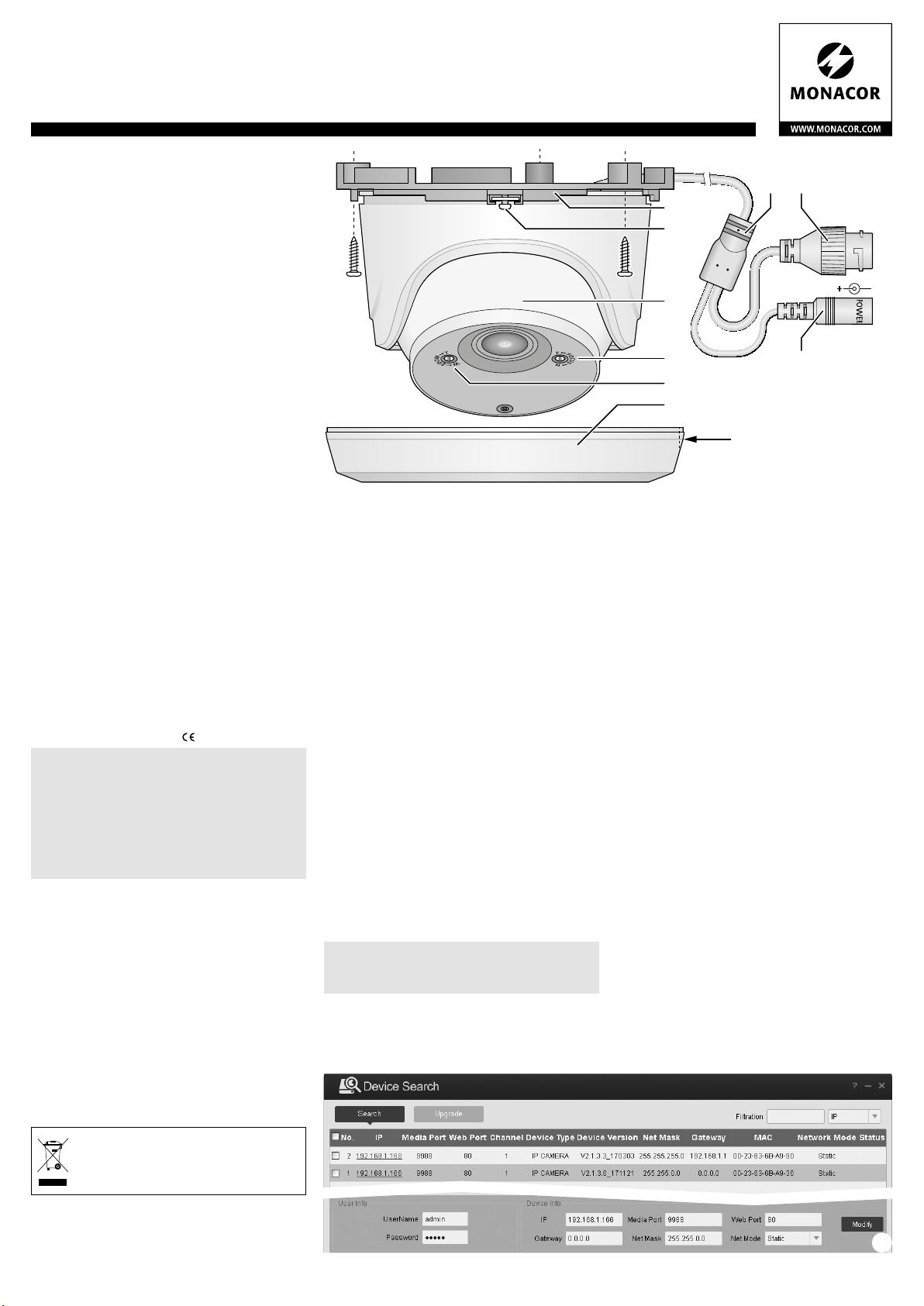
3 Montage
1) Um die optimale Montagestelle festzustellen,
sollte ein Probebetrieb erfolgen. Dazu die Kamera vorläufig in Betrieb nehmen (☞folgende
Kapitel).
2) Den Ring (6) ca. 15° nach rechts drehen und
nach unten vom Montagesockel (1) abziehen.
3) An der Montagestelle (z. B. Wand oder Decke)
drei Löcher für die Befestigung des Sockels (1)
bohren und ggf. ein Loch für das Anschlusskabel. Den Sockel dort festschrauben.
4) Soll das Kabel seitlich am Sockel herausgeführt
werden, die vorgesehene Aussparung (7) am
Ring ausschneiden.
5) Die Kamera (3) zum Ausrichten in ihrer Halterung drehen. Wenn erforderlich, die Feststellschraube (2) etwas lösen.
Vorsicht: Vermeiden Sie die direkte Ausrichtung der
Kamera auf starke Lichtquellen (z. B. Sonne).
Dies könnte die Lebensdauer des Bildsensors verkürzen.
6) Den Ring (6) wieder auf den Sockel (1) setzen
und durch Drehen nach links verriegeln.
4 Kamera anschließen
Die Anschlüsse (9, 10) und der Kabelverteiler (8)
sind nicht wetterfest. Sie müssen entsprechend
geschützt werden.
1) Die Kamera über die RJ45-Kupplung (9) mit
einem einzelnen Computer, einem lokalen
Computernetzwerk oder, z. B. über einen Router, mit größeren Computernetzwerken (Inter-
2) An die Kupplung (10) ein stabilisiertes 12-V-
5 Kamera in ein Netzwerk einbinden
Damit die Kamera zum Konfigurieren über einen
Computer direkt angesprochen werden kann, ist
ihre IP-Adresse vom Werk aus auf 192.168.1.168
voreingestellt.
kannt, zum Finden der Kamera im Netzwerk das
auf der beiliegenden CD enthaltene Programm
„Device Config Tool“ installieren und starten.
1) Das Netzwerk wird durchsucht und eine
2) Die Kamera durch Klicken auf die entsprechen-
3) Die Einstellungen nach Bedarf ändern:
1
2
3
4
5
7
net) verbinden. Alternativ die Kamera direkt an
einen Eingang eines IOR-Rekorders anschließen.
Netz gerät mit einer Dauerbelastbarkeit von 1 A
(z. B. PSS-1230DC oder PS-120WP) über einen
Hohlstecker ⌀ 5,5 / 2,1 mm (außen / innen) anschließen. Dabei die Polung beachten:
Mittelkontakt = +.
Alternativ lässt sich die Kamera auch über
das Netzwerkkabel versorgen (Power over
Ethernet IEEE 802.3af).
Ist die aktuelle Adresse der Kamera nicht be-
Liste aller gefundenen Kameras angezeigt
(☞Abb.2).
de Zeile auswählen. Im unteren Bereich werden
jetzt die aktuellen Einstellungen dieser Kamera
gezeigt.
IP-Adresse, Teilnetzmaske und Gateway-Adresse können statisch festgelegt werden (Option
„Net mode“ = „Static“ wählen). Dabei muss
für jede Kamera eine eindeutige IP-Adresse
eingegeben werden. Existiert in dem Netzwerk
869
LAN
12V
10
➀
➁
Page 2
IOC-2812DV Bestellnummer 18.9120
ELECTRONICS FOR SPECIALISTS ELECTRONICS FOR SPECIALISTS ELECTRONICS FOR SPECIALISTS ELECTRONICS FOR SPECIALISTS ELECTRONICS FOR SPECIALISTS ELECTRONICS FOR SPECIALISTS ELECTRONICS
ein DHCP-Server (z. B. im Router oder Netzwerk-Video rekorder), kann dieser Einstellungen für die Kamera automatisch vornehmen (Option „Net
Mode“ = „DHCP“ wählen); die automatisch vergebenen Werte sind dann
grau hinterlegt und können nicht geändert werden.
4) Auf die Schaltfläche „Modify“ klicken. Bei erfolgreicher Übertragung der
Änderungen wird „Modified successfully“ unter „Status“ angezeigt.
Hinweis: Für eine Änderung der Einstellungen müssen die richtigen Zugangsdaten
5) Für eine erneute Suche auf die Schaltfläche „ Search“ klicken.
der Kamera eingetragen sein (User Name, Password).
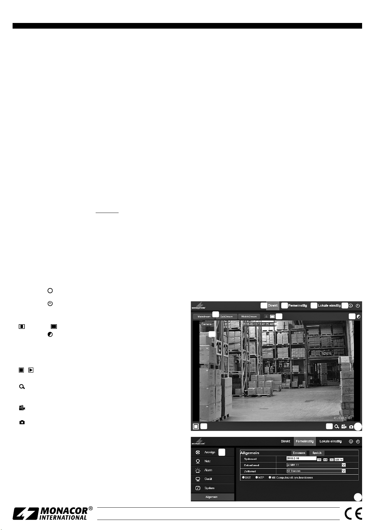
6 Kamera über einen Computer aufrufen
Die Bedienoberfläche der Kamera kann durch die Eingabe ihrer IP-Adresse in
der Adresszeile des Programms Windows Internet Explorer (IE, Version 6 oder
höher) aufgerufen werden. Dazu müssen die IP-Adressen vom Computer
und der Kamera demselben Teilnetz angehören.
Beim Aufruf der Kamera erscheint zunächst das Anmeldefenster. Hier
die Sprache für die Benutzeroberfläche wählen; die folgende Beschreibung
bezieht sich auf die Einstellung „Deutsch“. Anschließend den Benutzernamen und das Kennwort eingeben (Vorgabe für beide Eingaben: admin).
In den Kameraeinstellungen können später eigene Anmeldedaten festgelegt
werden.
Wichtig: Gegen einen unbefugten Zu gang sollte zumindest das Kennwort geändert
Wird die Kamera von einem Computer erstmalig aufgerufen, erscheint anstelle des Anmeldefensters zunächst die Aufforderung, eine Erweiterung
(plugin) für den IE zu installieren: Auf download klicken, die Installationsdatei
„IPC_Web_Plugin.exe“ auf dem Computer speichern, den IE schließen und
die Datei ausführen. Anschließend die Kamera über den IE erneut aufrufen.
Wenn nötig, müssen für die Verwendung der installierten ActiveX-Erweiterungen die Sicherheitseinstellungen des IE gelockert werden.
Ist die Verbindung zur Kamera aufgebaut, erscheint die in Abb. 3 gezeigte
Ansicht mit dem aktuellen Kamerabild und folgenden Bedienmöglichkeiten:
a
b
c
d
e
f
g
h
i
j
: Vergrößerung eines Bildausschnitts: Mit der Maus über dem ge-
: Starten / Beenden einer Videoaufzeichnung „Eintragung“ auf dem
: Schnappschuss-Funktion zum Speichern einer Mo mentaufnahme
Zum Ändern der Einstellungen für die Kamera, über den Reiter b auf die
Ansicht „Ferneinstellung“ umschalten (☞Abb. 4). Am linken Rand (k) die
gewünschte Rubrik für die Einstellungen auswählen. So lässt sich z. B. unter
„System Allgemein“ die aktuelle Zeit für die Kamera einstellen.
Schalt fläche „Speichern“ klicken. Zum Laden der aktuellen Einstellungen aus
der Kamera auf die Schaltfläche „Erneuern“ klicken.
Windows ist ein registriertes Warenzeichen der Microsoft Corporation in den USA und anderen Ländern.
werden. Ein geändertes Kennwort gut merken. Ein Zurücksetzen der Kameraeinstellungen ist nur mit Kenntnis des Kennworts möglich!
Ansicht „Direkt“ mit Anzeige des Kamerabilds
Ansicht „Ferneinstellung“ zum Ändern der Kameraeinstellungen
Ansicht „Lokale Einstellungen“ zum Vorgeben der Speicherorte für
Videoaufzeichnungen und Momentaufnahmen auf dem Computer
Schaltfläche i: Beim Darüberhalten des Mauszeigers werden der aktu-
elle Benutzername und Versionsnummern der Software angezeigt
Schaltfläche zum Abmelden
Auswahl eines Streams: Mainstream, Substream, Mobilestream
Wahl des Seitenverhältnisses für die Anzeige des Kamerabildes:
= original, = angepasst
Schaltfläche zum Einblenden der Bildeinstellungen: Farbton, Hellig-
keit, Kontrast, Farbsättigung und Bildschärfe
Kamerabild mit eingeblendeten Informationen
Mit einem Doppelklick auf das Bild die Vollbilddarstellung ein-/ausschalten.
/ : Beenden / Starten der Bildübertragung
Funktionsleiste mit folgenden Funktionen
wünschten Bildausschnitt einen Rahmen aufziehen.
rechte Maustaste ➾ gesamtes Bild
Computer
als Bild
Nach dem Ändern einer Einstellung zum Speichern der Änderung auf die
7 Brennweite und Fokus einstellen
Die Einstellung des Objektivs kann an der Vorderseite der Kamera mithilfe
eines kleinen Schraubendrehers durchgeführt werden. Durch Drehen der
entsprechenden Einstellschraube die Brennweite ZOOM (5) und die Schärfe
FOCUS (4) einstellen.
8 Technische Daten
Bildabtaster: . . . . . . . . . . CMOS, 8,5 mm (1⁄3 ”)
Objektiv: . . . . . . . . . . . . . 1 : 1,2 / 2,8 – 12 mm
Blickwinkel: . . . . . . . . . . . 35° – 89°
Auflösung: . . . . . . . . . . . max. 2048 × 1536 Bildpunkte
Elektronischer Verschluss: 1⁄5 – ½0 000 s
Protokolle: . . . . . . . . . . . HTTP, HTTPS, TCP/IP, RTSP, DHCP, NTP, PPoE,
ONVIF2.60 u. a.
Kompressionsverfahren: . MPEG-4 H.264, H.265, MJPEG
Videostreaming: . . . . . . . Mainstream 256 – 8192 kbit /s
Substream 128 – 4096 kbit /s
Mobilestream 8 – 1536 kbit /s
Netzwerk: . . . . . . . . . . . . Ethernet 10 / 100 MBit / s
Einsatztemperatur: . . . . . −10 °C bis +50 °C
Schutzart: . . . . . . . . . . . . IP 66
Stromversorgung: . . . . . . ⎓12 V/1 A oder PoE IEEE 802.3af
Abmessungen: . . . . . . . . ⌀ 151 mm × 113 mm
Gewicht: . . . . . . . . . . . . . 600 g
Änderungen vorbehalten.
i
h
e
a
f
b
c
j
d
g
➂
k
MONACOR INTERNATIONAL GmbH & Co. KG • Zum Falsch 36 • 28307 Bremen • Germany
Copyright© by MONACOR INTERNATIONAL. All rights reserved.
➃
A-1902.99.01.04.2018
Page 3

IOC-2812DV Order Number 18.9120
ELECTRONICS FOR SPECIALISTS ELECTRONICS FOR SPECIALISTS ELECTRONICS FOR SPECIALISTS ELECTRONICS FOR SPECIALISTS ELECTRONICS FOR SPECIALISTS ELECTRONICS
Outdoor Network Camera
These instructions are intended for installers
of video surveillance systems. Please read the
English
instructions carefully prior to installation and
keep them for later reference.
1 Applications
The camera IOC-2812DV is specially designed for
video surveillance systems based on computer
networks. Its housing is weatherproof (IP 66);
therefore, the camera is also suited for outdoor
applications. It is equipped with a 3 megapixel
image sensor and a zoom lens (2.8 – 12 mm). The
camera features include mirror image, masking
of image areas, motion detection and intelligent
functions for image analysis and data reduction
(e. g. ROI). In the dark, the integrated IR LEDs will
illuminate a surveillance zone of up to 40 m and
the camera will switch to B / W mode. The camera
is provided with an integrated web server with
3-way video streaming. For correct configuration,
knowledge in network technology is indispensable.
The camera can be operated in combination
with a network video recorder (e. g. IOR-…*) or
operated independently via web browser.
*Hint: If this camera model does not appear in the list
of the recorder used, select the ONVIF protocol.
2 Important Notes
The camera corresponds to all relevant directives
of the EU and is therefore marked with .
CAUTION When it gets dark, the infrared LEDs
will switch on. When setting up the camera,
never look directly into the lit infrared LEDs at
close range. The infrared light may cause eye
irritation. However, the infrared radiation is far
below the emission limit and rated risk-free according to EN 62471.
Protect the camera against extreme tempera-
•
tures (admissible ambient temperature range:
−10 °C to +50 °C).
Never use aggressive detergents or chemicals
•
when cleaning the camera.
No guarantee claims for the camera and no lia-
•
bility for any resulting personal damage or material damage will be accepted if the camera is
used for other purposes than originally intended, if it is not correctly connected or operated,
or if it is not repaired in an expert way. Likewise,
no liability will be accepted for any data loss
due to operating errors or a defect or for any
consequential damage caused by this data loss.
If the camera is to be put out of operation definitively, take it to a local recycling plant for a disposal which is not
harmful to the environment.
3 Installation
1) A test operation is recommended in order to
find the best mounting location. For this purpose, operate the camera temporarily (☞next
chapters).
2) Turn the ring (6) clockwise by approximately
15 degrees and pull the ring from the base (1).
3) At the mounting location (e. g. wall or ceiling),
drill three holes for fixing the base (1) and, if
necessary, drill a hole for the connection cable.
Fasten the base at the mounting location.
4) To guide the cable through the side of the base,
open the knock-out hole (7) of the ring.
5) To align the camera (3), turn the camera in its
support. Release the locking screw (2) as required.
Caution: Do not aim the camera directly at the sun or
other bright light sources; this may reduce
the life of the image sensor.
6) Place the ring (6) on the base (1) again and turn
the ring counter-clockwise to secure it.
4 Connecting the Camera
The connections (9, 10) and the cable splitter (8)
are not weatherproof; protect them accordingly.
1) Connect the camera via the RJ45 connector
(9) to an individual computer, a local computer
network or, e. g. via a router, to larger computer
networks (Internet). Alternatively, connect the
camera directly to the input of an IOR recorder.
2) Connect a regulated 12 V power supply unit
5 Connecting the Camera to a Network
To be able to directly address the camera for configuration via computer, its IP address is factoryset to 192.168.1.168.
camera, install and start the program “Device
Config Tool” from the CD provided to find the
camera in the network.
1) The program will search the network and show
2) Click the corresponding line to select the cam-
3) Change the settings as required:
1
2
3
4
5
7
with a permanent rating of 1 A (e. g. PSS1230DC or PS-120WP) via a DC power connector ⌀ 5.5 / 2.1 mm (outside / inside) to the
connector (10). Always observe the correct
polarity: centre contact = +.
Alternatively, use the network cable (Power
over Ethernet IEEE 802.3af) to supply the camera with power.
If you do not know the current address of the
a list of all cameras found (☞fig. 2).
era from the list. The current settings of this
camera can be found at the bottom.
IP address, subnet mask and gateway address
can be defined as static values (select the option “Net mode = Static”). Enter a unique IP
address for each camera. If a DHCP server is
available in the network (e. g. in the router or
network video recorder), this server will be able
to automatically make settings for the camera
(select the option “Net Mode = DHCP”). The
values assigned automatically are highlighted
in grey and cannot be changed.
869
LAN
12V
10
➀
➁
Page 4

IOC-2812DV Order Number 18.9120
ELECTRONICS FOR SPECIALISTS ELECTRONICS FOR SPECIALISTS ELECTRONICS FOR SPECIALISTS ELECTRONICS FOR SPECIALISTS ELECTRONICS FOR SPECIALISTS ELECTRONICS FOR SPECIALISTS ELECTRONICS
4) Click the button “Modify”. After successful transmission of the modifications, the message “Modified successfully” will appear below “Status”.
Note: To change the settings, it is necessary to enter the correct log-in data of the
camera (user name, password).
5) For a new search, click the button “Search”.
6 Calling up the Camera via Computer
To call up the user interface of the camera, enter its IP address in the address
bar of the program Windows Internet Explorer (IE, version 6 or higher). The
IP addresses of the computer and of the camera must be in the same subnet.
When the camera is called up, the log-in window will appear. Select the
language for the user interface. The description below refers to English. Then
enter the user name and the password (default setting for both: admin).
Individual log-in data can be defined later in the camera settings.
Important: To prevent unauthorized access, change at least the password. Always
When the camera is called up from a computer for the first time, a request
to install an extension (plugin) for the IE will appear instead of the log-in
window. Click on download, save the installation file “IPC_Web_Plugin.exe”
to the computer, close the IE and execute the file. Then call up the camera
again via the IE. If necessary, reduce the security settings of the IE to be able
to use the installed ActiveX extensions.
When the connection to the camera has been established, the view with
the current camera image (fig. 3) will be displayed. The following options
are available:
View “Live” with display of camera image
a
View “Remote Setting” to change the camera settings
b
View “Local Setting” to define the storage locations for video record-
c
Button i: When the mouse cursor is moved over this button, the cur-
d
Selection of a stream: Mainstream, Substream, Mobilestream
e
Selection of the aspect ratio for the camera image:
f
Button to insert the image settings: hue, brightness, contrast, satura-
g
Camera image with information inserted
h
/ : Stop/Start of image transmission
i
Toolbar with the following functions:
j
: Zooming in image areas: drag the mouse to select the desired
: Start/Stop of a video recording on the computer
: Snapshot function to save a snapshot as an image file
To change the settings for the camera, select the tab b to go to the view
“Remote Setting” (☞fig. 4). On the left (k), select the desired category
for the settings. To set, for example, the current time for the camera, go to
“System DateTime”.
the current settings from the camera, click the button “Refresh”.
Windows is a registered trademark of Microsoft Corporation in the USA and other countries.
make sure to remember the new password. You need the password to
reset the camera settings!
ings and snapshots on the computer
rent user name and the software version numbers will be shown;
button to log out
= original, = adapted
tion and sharpness
Double-click the image to activate / deactivate the full-screen mode.
image area
right mouse button ➾ entire image
To save a setting that has been changed, click the button “Save”. To load
7 Adjusting the Focal Length and the Focus
To adjust the lens, use a small screwdriver: Turn the corresponding setscrew
on the front of the camera to adjust the focal length ZOOM (5) and the
sharpness FOCUS (4).
8 Specifications
Image sensor: . . . . . . . . . CMOS, 8:5 mm (1⁄3 ”)
Lens: . . . . . . . . . . . . . . . . 1 : 1.2 / 2.8 – 12 mm
Viewing angle: . . . . . . . . 35° to 89°
Resolution: . . . . . . . . . . . 2048 × 1536 pixels max.
Electronic shutter: . . . . . . 1⁄5 – ½0 000 s
Protocols: . . . . . . . . . . . . HTTP, HTTPS, TCP/IP, RTSP, DHCP, NTP, PPoE,
ONVIF 2.60, etc.
Compression: . . . . . . . . . MPEG-4 H.264, H.265, MJPEG
Video streaming: . . . . . . . Mainstream 256 – 8192 kbit /s
Substream 128 – 4096 kbit /s
Mobilestream 8 – 1536 kbit /s
Network: . . . . . . . . . . . . Ethernet 10 / 100 Mbit/s
Ambient temperature: . . −10 °C to +50 °C
IP rating: . . . . . . . . . . . . . IP 66
Power supply: . . . . . . . . . ⎓12 V/1 A or PoE IEEE 802.3af
Dimensions: . . . . . . . . . . ⌀ 151 mm × 113 mm
Weight: . . . . . . . . . . . . . 600 g
Subject to technical modification.
h
e
a
f
b
c
d
g
i
k
MONACOR INTERNATIONAL GmbH & Co. KG • Zum Falsch 36 • 28307 Bremen • Germany
Copyright© by MONACOR INTERNATIONAL. All rights reserved.
j
A-1902.99.01.04.2018
➂
➃
Page 5

IOC-2812DV Référence numérique 18.9120
ELECTRONICS FOR SPECIALISTS ELECTRONICS FOR SPECIALISTS ELECTRONICS FOR SPECIALISTS ELECTRONICS FOR SPECIALISTS ELECTRONICS FOR SPECIALISTS ELECTRONICS
Caméra réseau pour l’extérieur
Cette notice s’adresse aux installateurs d’installations de surveillance vidéo. Veuillez lire la
présente notice avant l’installation et conser-
Français
vez-la pour pouvoir vous y reporter ultérieurement.
1 Possibilités d’utilisation
La caméra IOC-2812DV est spécialement conçue
pour une utilisation dans des installations de
surveillance vidéo basées sur des réseaux informatiques. Grâce à son boîtier protégé contre les
intempéries (type de protection IP 66), elle est également adaptée pour une installation en extérieur.
Elle est dotée d’un capteur d’image 3 mégapixels
et d’un objectif à focale variable (2,8 – 12 mm) et
propose, entre autres, la visualisation en image
miroir, le masquage de zones d’image et la détection de mouvements ainsi que des fonctions intelligentes pour l’analyse d’image et la réduction des
données (par exemple ROI). Dans la pénombre,
les LEDs infrarouges intégrées éclairent la zone de
surveillance jusqu’à 40 m et la caméra commute
sur le mode noir et blanc. La caméra dispose d’un
serveur web intégré avec streaming vidéo ×3.
Pour l’installation correcte, des connaissances en
technologie réseau sont indispensables.
La caméra peut être utilisée en combinaison
avec un enregistreur vidéo réseau (p. ex. IOR-…*)
ou seule, via un navigateur internet.
*Conseil : Si le modèle de la caméra n’existe pas dans
la liste de l’enregistreur utilisée, sélectionnez
le protocole ONVIF.
2 Conseils d’utilisation importants
La caméra répond à toutes les directives nécessaires de l’Union européenne et porte donc le
symbole .
ATTENTION Les LEDs infrarouges s’allument
dans la pénombre. Ne regardez jamais directement les LEDs allumées de proximité lors de
l’installation de la caméra. La lumière infrarouge
peut engendrer des irritations des yeux. Le
rayonnement infrarouge est cependant loin du
seuil limite d’émission et considéré sans risque
selon la norme EN 62471.
Protégez la caméra des températures extrêmes
•
(plage de température de fonctionnement autorisée : −10 °C à +50 °C).
Pour le nettoyage, n’utilisez pas de produits
•
chimiques ou de détergents agressifs.
Nous déclinons toute responsabilité en cas de
•
dommages corporels ou matériels résultants
si la caméra est utilisée dans un but autre que
celui pour lequel elle a été conçue, si elle n’est
pas correctement branchée ou utilisée ou si
elle n’est pas réparée par une personne habilitée; en outre, la garantie deviendrait caduque.
De même, notre responsabilité ne saurait être
engagée en cas de pertes de données et leurs
conséquences, causées par une mauvaise utilisation ou un défaut.
Lorsque la caméra est définitivement retirée du service, vous devez la déposer
dans une usine de recyclage de proximité pour contribuer à son élimination non
polluante.
3 Montage
1) Pour définir le lieu optimal de montage, il faut
effectuer un test de fonctionnement. Pour ce
faire, mettez la caméra en fonction de manière
temporaire (☞chapitres suivants).
2) Tournez l’anneau (6) de 15° environ vers la
droite et retirez-le du socle de montage en le
tirant vers le bas.
3) Sur l’emplacement de montage (par exemple
mur ou plafond), percez trois trous pour fixer
le socle (1) et si besoin, un trou pour le câble
de branchement. Vissez le socle.
4) Si le câble doit sortir latéralement du socle, découpez l’encoche prévue (7) sur l’anneau.
5) Tournez la caméra (3) dans son support pour
l’orienter. Si besoin, desserrez un peu la vis (2).
Attention : Evitez d’orienter la caméra directement
vers des sources puissantes de lumière
(par exemple soleil). Cela pourrait diminuer la durée de vie du capteur d’image.
6) Replacez l’anneau (6) sur le socle (1) et verrouillez en tournant vers la gauche.
4 Branchement de la caméra
Les branchements (9, 10) et le répartiteur de
câble (8) ne sont pas protégés contre les intempéries. Ils doivent être protégés en conséquence.
1) Reliez la caméra via la fiche femelle RJ45 (9) à
un ordinateur individuel, un réseau local d’ordinateurs ou, par exemple via un routeur, à des
réseaux informatiques plus importants (internet). A la place, la caméra peut être directement reliée à l’entrée d’un enregistreur IOR.
2) Reliez une alimentation stabilisée 12 V avec une
5 Intégrer la caméra dans le réseau
Pour pouvoir adresser directement la caméra pour
une configuration via l’ordinateur, son adresse IP
est réglée en usine sur 192.168.1.168.
connue, installez le programme «Device Config
Tool» depuis le CD livré pour trouver la caméra
dans le réseau et démarrez.
1) Le réseau est parcouru et une liste de toutes
2) Sélectionnez la caméra en cliquant sur la ligne
3) Si besoin, modifiez les réglages :
1
2
3
4
5
7
puissance continue de 1 A (p. ex. PSS-1230DC
ou PS-120WP) à la fiche femelle(10) en utilisant
une fiche alimentation ⌀ 5,5 / 2,1 mm (extérieur /
intérieur). Veillez à respecter la polarité :
Contact médian = +
A la place, la caméra peut être alimentée via le câble réseau (Power over Ethernet
IEEE802.3af).
Si l’adresse actuelle de la caméra n’est pas
les caméras trouvées s’affiche (☞chapitre 2).
correspondante. Dans la zone inférieure, les
réglages actuels de cette caméra sont affichés.
L’adresse IP, le masque sous-réseau et l’adresse
Gateway peuvent être définies comme statiques (option «Net Mode» = «Static»). Pour
chaque caméra, une adresse IP unique doit
être saisie. Si dans le réseau il existe un serveur DHCP, (par exemple dans le routeur ou
l’enregistreur vidéo réseau), il peut effectuer
automatiquement ces réglages pour la caméra (option «Net mode» = «DHCP». Les valeurs
attribuées automatiquement apparaissent sur
un fond gris et ne peuvent pas être modifiées.
869
LAN
12V
10
➀
➁
Page 6

IOC-2812DV Référence numérique 18.9120
ELECTRONICS FOR SPECIALISTS ELECTRONICS FOR SPECIALISTS ELECTRONICS FOR SPECIALISTS ELECTRONICS FOR SPECIALISTS ELECTRONICS FOR SPECIALISTS ELECTRONICS FOR SPECIALISTS ELECTRONICS
4) Cliquez sur le bouton «Modify». Lorsque la transmission des modifications
est réussie, le message «Modified successfully» s’affiche sous «Status».
Remarque : Pour modifier le réglage, il faut saisir les données d’accès correctes de
5) Cliquez sur le bouton «Search» pour une nouvelle recherche.
la caméra (User Name, Password).
6 Appeler la caméra via un ordinateur
L’interface utilisateur de la caméra peut être appelée en saisissant son adresse
IP dans la barre d’adresse du programme Windows Internet Explorer (IE, version 6 ou supérieure). Pour ce faire, les adresses IP de l’ordinateur et de la
caméra doivent appartenir au même sous-réseau.
Lorsque vous appelez la caméra, la fenêtre d’enregistrement s’affiche en
premier. Sélectionnez la langue pour l’interface utilisateur : la description
ci-après se réfère au réglage «English». Ensuite, saisissez le nom utilisateur
et le mot de passe (préréglage pour les deux informations : admin). Vous
pourrez ultérieurement définir vos propres données d’enregistrement dans
les réglages de la caméra.
Important : Modifiez au moins le mot de passe pour éviter tout accès non autorisé.
Si la caméra est appelée pour la première fois depuis un ordinateur, la demande d’installer une extension (plugin) pour l’IE s’affiche à la place de
la fenêtre d’enregistrement : cliquez sur download, sauvegardez le fichier
d’installation «IPC_Web_Plugin.exe» sur l’ordinateur, fermez l’IE et exécutez le fichier. Ensuite, appelez à nouveau la caméra via l’IE. Si besoin, il faut
diminuer les réglages de sécurité de l’IE pour pouvoir utiliser les extensions
ActiveX installées.
Lorsque la liaison avec la caméra est établie, la fenêtre présentée sur le
schéma 3 s’affiche avec l’image actuelle de la caméra ainsi que les possibilités
suivantes d’utilisation :
Visualisation «Live» avec affichage de l’image de la caméra
a
Visualisation «Remote Setting» pour modifier les réglages de la caméra
b
Visualisation «Local Setting» pour définir les emplacements de mé-
c
morisation pour les enregistrements vidéo et les captures d’écran sur
l’ordinateur.
Bouton i : si vous passez la souris dessus, le nom actuel de l’utilisateur
d
et les numéros de version du software s’affichent.
Appuyez sur pour quitter.
Sélection d’un stream : Mainstream, Substream, Mobilestream
e
Sélection du rapport pour l’affichage de l’image de la camera :
f
Bouton pour afficher les réglages image : teinte, luminosité,
g
contraste, saturation et netteté
Image caméra avec les informations affichées
h
Par un double clic sur l’image, activez / désactivez la visualisation plein
écran.
/ : Arrêter / Démarrer la transmission vidéo
i
Barre de fonctions avec les fonctions suivantes
j
: agrandissement d’un segment d’image : avec la souris, tirez un
: Démarrage /Arrêt d’un enregistrement vidéo sur l’ordinateur
: Fonction capture écran pour mémoriser un instantané comme
Pour modifier les réglages pour la caméra, sélectionnez l’onglet b pour aller
à la visualisation «Remote Setting» (☞schéma 4). Sur le bord gauche(k),
sélectionnez la rubrique voulue pour les réglages. Ainsi, sous «System
DateTime», effectuez par exemple le réglage pour l’heure actuelle pour
la caméra.
Une fois le réglage modifié, sauvegardez-le en cliquant sur le bouton
«Save». Pour charger les réglages actuels de la caméra, cliquez sur le bouton
«Refresh».
Windows est une marque déposée de Microsoft Corporation aux Etats-Unis et dans les autres pays.
Pensez à bien noter le mot de passe modifié. Une réinitialisation de la
caméra n’est possible que si vous connaissez le mot de passe.
= original, = adapté
cadre sur le segment d’image voulu
touche droite de la souris ➾ image totale
fichier image
7 Réglage de la focale et de la netteté
Le réglage de l’objectif peut être effectué à l’aide d’un petit tournevis sur la
face avant de la caméra. En tournant la vis de réglage correspondante, réglez
la focale ZOOM (5) et la netteté FOCUS (4).
8 Caractéristiques techniques
Capteur d’image : . . . . . . CMOS, 8,5 mm (1⁄3 ”)
Objectif : . . . . . . . . . . . . . 1 : 1,2 / 2,8 – 12 mm
Angle : . . . . . . . . . . . . . . 35° – 89°
Résolution : . . . . . . . . . . . 2048 × 1536 points d’image max.
Obturation électronique : 1⁄5 – ½0 000 s
Protocoles : . . . . . . . . . . . HTTP, HTTPS, TCP/IP, RTSP, DHCP, NTP, PPoE,
ONVIF2.60 etc.
Processus compression : . MPEG-4 H.264, H.265, MJPEG
Streaming vidéo : . . . . . . Mainstream 256 – 8192 kbit /s
Substream 128 – 4096 kbit /s
Mobilestream 8 – 1536 kbit /s
Réseau : . . . . . . . . . . . . . Ethernet 10 / 100 MBit / s
Température fonc. : . . . . . −10 °C à +50 °C
Type protection : . . . . . . . IP 66
Alimentation : . . . . . . . . . ⎓12 V/1 A ou PoE IEEE 802.3af
Dimensions : . . . . . . . . . . ⌀ 151 mm × 113 mm
Poids : . . . . . . . . . . . . . . . 600 g
Tout droit de modification réservé.
i
h
e
a
f
b
c
j
d
g
➂
k
CARTONS ET EMBALLAGE
PAPIER À TRIER
MONACOR INTERNATIONAL GmbH & Co. KG • Zum Falsch 36 • 28307 Bremen • Germany
Copyright© by MONACOR INTERNATIONAL. All rights reserved.
➃
A-1902.99.01.04.2018
 Loading...