

Page 1
Netzwerk-PTZ-Außenkamera
Outdoor PTZ Network Camera
Caméra extérieure PTZ réseau
INC-4757 PTZ
Bestell-Nr. • Order No. • Réf. num. 18.0006
BEDIENUNGSANLEITUNG
INSTRUCTION MANUAL
MODE D’EMPLOI
ELECTRONICS FOR SPECIALISTS ELECTRONICS FOR SPECIALISTS ELECTRONICS FOR SPECIALISTS ELECTRONICS FOR SPECIALISTS
Page 2
6
141615
5
➀
4
7
LAN
8
3
12V
9
Audio Input
10
Audio Output
11
Alarm
IN1
IN COM
IN2
12
OUT COM
2
OUT1
Ground
13
Alarm
IN 1 violett purple violet
1
IN COM grau grey gris
IN 2 gelb yellow jaune
OUT COM orange orange orange
OUT 1 weiß white blanc
2
➁
Page 3

Deutsch .......... Seite 4
English ........... Page 14
Français .......... Page 24
ELECTRONICS FOR SPECIALISTS ELECTRONICS FOR SPECIALISTS ELECTRONICS FOR SPECIALISTS ELECTRONICS FOR SPECIALISTS
3
Page 4

Netzwerk-PTZ-Außenkamera
Diese Anleitung richtet sich an Installateure von
Video überwachungsanlagen. Bitte lesen Sie die
Anleitung vor der Installation gründlich durch
Deutsch
und heben Sie sie für ein späteres Nachlesen auf.
Auf Seite 2 finden Sie alle beschriebenen
Montageteile und Anschlüsse.
Inhalt
1 Verwendungsmöglichkeiten � � � � � � � � 4
2 Sicherheitshinweise � � � � � � � � � � � � � 5
3 Montage � � � � � � � � � � � � � � � � � � � 5
4 Kamera anschließen� � � � � � � � � � � � � 6
5 Kamera in ein Netzwerk einbinden � � � � 6
6 Kamera über einen Computer aufrufen � �7
6�1 Sensor-Menü� � � � � � � � � � � � � � � � � 10
6�2 PTZ-Steuerung � � � � � � � � � � � � � � � � 10
6�2�1 Speichermöglichkeiten� � � � � � � � � � � 11
7 Zurücksetzen der Kamera � � � � � � � � 12
8 Technische Daten � � � � � � � � � � � � � 12
1 Verwendungsmöglichkeiten
Die Kamera INC-4757PTZ ist speziell für den
Einsatz in Videoüberwachungsanlagen auf der
Basis von Computer-Netzwerken konzipiert.
Durch ihr wetterfestes Ge häuse ist sie auch für
die Außeninstallation geeignet. Sie ist mit einem
3-Megapixel-Bild sensor und einem Zoom-Objektiv mit Autofokus-Funktion und gesteuerter
Blende ausgestattet. Die Kamera bietet u. a.
Bildspiegelung, Maskierung von Bildbereichen
und Bildanalysefunktionen (wie z. B. Bewegungserkennung). Mit der Autotracking-Funktion kann die Kamera selbstständig bewegten
Objekten folgen. Bei Dunkel heit leuchten die
eingebauten Infrarot-LEDs den Überwachungsbereich bis 100 m aus und die Kamera schaltet
auf Schwarzweißbetrieb um. Die Kamera verfügt
über einen eingebauten Webserver mit 3-fachVideo streaming. Für die korrekte Einrichtung
sind unbedingt Netzwerktechnik-Kennt nisse
er forderlich.
Die Kamera kann in Verbindung mit einem
Netzwerk-Videorekorder (z. B. NWR-…*) genutzt werden oder eigenständig über einen
Webbrowser. Die Steuerung der Kamerabewegung (Schwenken und Neigen) sowie des
Objektivs (Zoom, Blende und Fokus) kann über
den Webbrowser oder einen Rekorder der
NWR-Serie erfolgen. Die Kamera verfügt über
einen Audio eingang und einen Audioausgang,
sodass eine gegenseitige Kom munikation über
einen Computer möglich ist. Ein Schaltausgang erlaubt das Schalten von Geräten, z. B.
durch die integrierte Bewegungserkennung
ausgelöst. Zusätzlich verfügt die Kamera über
zwei Alarmeingänge, über die z. B. eine Aufzeichnung oder eine E-Mail-Benachrichtigung
gestartet werden kann. Ein Steckplatz für eine
Speicherkarte erlaubt die Videoaufzeichnung
in der Kamera, nach Zeitplan oder durch eine
Bild analysefunktion ausgelöst.
* Tipp: Ist das Kameramodell in der Liste des verwende-
ten Rekorders nicht vorhanden, das ONVIF-Protokoll wählen.
4
Page 5
2 Sicherheitshinweise
Die Geräte (Kamera und Netzgerät) entsprechen
allen relevanten Richtlinien der EU und sind deshalb mit gekennzeichnet.
WARNUNG Das Netzgerät wird mit lebens-
gefährlicher Netzspannung versorgt. Nehmen Sie daran keine
Eingriffe vor. Es besteht die Gefahr eines elektrischen Schlages.
Schützen Sie die Kamera vor extremen Tem-
•
peraturen (zulässige Einsatztemperatur −40 °C
bis +60 °C).
Setzen Sie das Netzgerät nur im Innenbe-
•
reich ein und schützen Sie es vor Tropf- und
Spritzwasser und hoher Luftfeuchtigkeit. Der
zulässige Einsatztemperaturbereich beträgt
0 – 40 °C.
Nehmen Sie die Geräte nicht in Betrieb und
•
ziehen Sie sofort den Netzstecker des Netzgeräts aus der Steckdose:
1. wenn sichtbare Schäden an einem der Geräte oder am Netzkabel vorhanden sind,
2.
wenn nach einem Sturz oder Ähnlichem der
Verdacht auf einen Defekt besteht,
3. wenn Funktionsstörungen auftreten.
Lassen Sie die Geräte in jedem Fall in einer
Fachwerkstatt reparieren.
Ziehen Sie den Netzstecker nie am Kabel aus
•
der Steckdose, fassen Sie immer am Stecker an.
Verwenden Sie zum Reinigen des Netzgeräts
•
nur ein trockenes, weiches Tuch, niemals Chemikalien oder Wasser. Die Kamera kann auch
mit einem feuchten Tuch und einem milden
Reinigungsmittel gesäubert werden.
Werden die Geräte zweckentfremdet, nicht
•
richtig angeschlossen, falsch bedient oder
nicht fachgerecht repariert, kann keine Haftung für daraus resultierende Sach- oder Personenschäden und keine Garantie für die Geräte übernommen werden. Ebenso kann keine
Haftung für durch Fehlbedienung oder durch
einen Defekt entstandene Datenverluste und
deren Folgeschäden übernommen werden.
Sollen die Geräte endgültig aus dem
Betrieb genommen werden, übergeben
Sie sie zur umweltgerechten Entsorgung
einem ört lichen Recyclingbetrieb.
3 Montage
1)
Um die optimale Montagestelle festzustellen, sollte ein Probebetrieb erfolgen. Dazu
die Kamera vorläufig in Betrieb nehmen
(☞folgende Kapitel). Lassen Sie zur Vermeidung von Kratzern während der Montage
die Schutzfolie auf der Kuppel (Handschuhe
liegen bei).
VORSICHT Bei Dunkelheit schalten sich die
IR-LEDs (2) ein. Blicken Sie beim Einrichten
der Kamera nicht aus der Nähe direkt in die
eingeschalteten IR-LEDs. Das Infrarotlicht
kann zu einer Reizung der Augen führen.
Die IR-Strahlung liegt allerdings weit unterhalb des Emissionsgrenzwertes und ist
risikofrei eingestuft nach EN 62471.
2) Den Deckel (1) des Fachs auf der Rückseite
des Kameragehäuses nach Lösen der beiden
Schrauben öffnen und die Transportsicherung (☞Pfeil in Abb. 3) der Kamera entfernen. Den Deckel danach wieder verschließen.
Ebenso die Klebestreifen zum beweglichen
Teil der Kamera entfernen.
Transportsicherung
➂
3)
An der Montagestelle vier Löcher für die
Befestigung der Montageplatte (6) der
Wandhalterung und ggf. ein Loch für das
An schluss kabel bohren (das Kabel kann alternativ durch eine der Durchbruchstellen seitlich oder unterhalb des Sockels herausgeführt
werden). Eine Bohrschablone liegt bei. Bei
Bedarf die beiliegenden Dübel verwenden.
4)
Das Kabel der Kamera durch das Rohr der
Wandhalterung führen und die Halterung mit
den drei Inbusschrauben (4) auf der Oberseite
der Kamera befestigen. Mit der Schraube (5)
die Kamera gegen Verdrehen sichern.
5)
Die Wandhalterung mit den vier langen
Kreuzschlitzschrauben an der Montage stelle
befestigen.
Deutsch
5
Page 6

4 Kamera anschließen
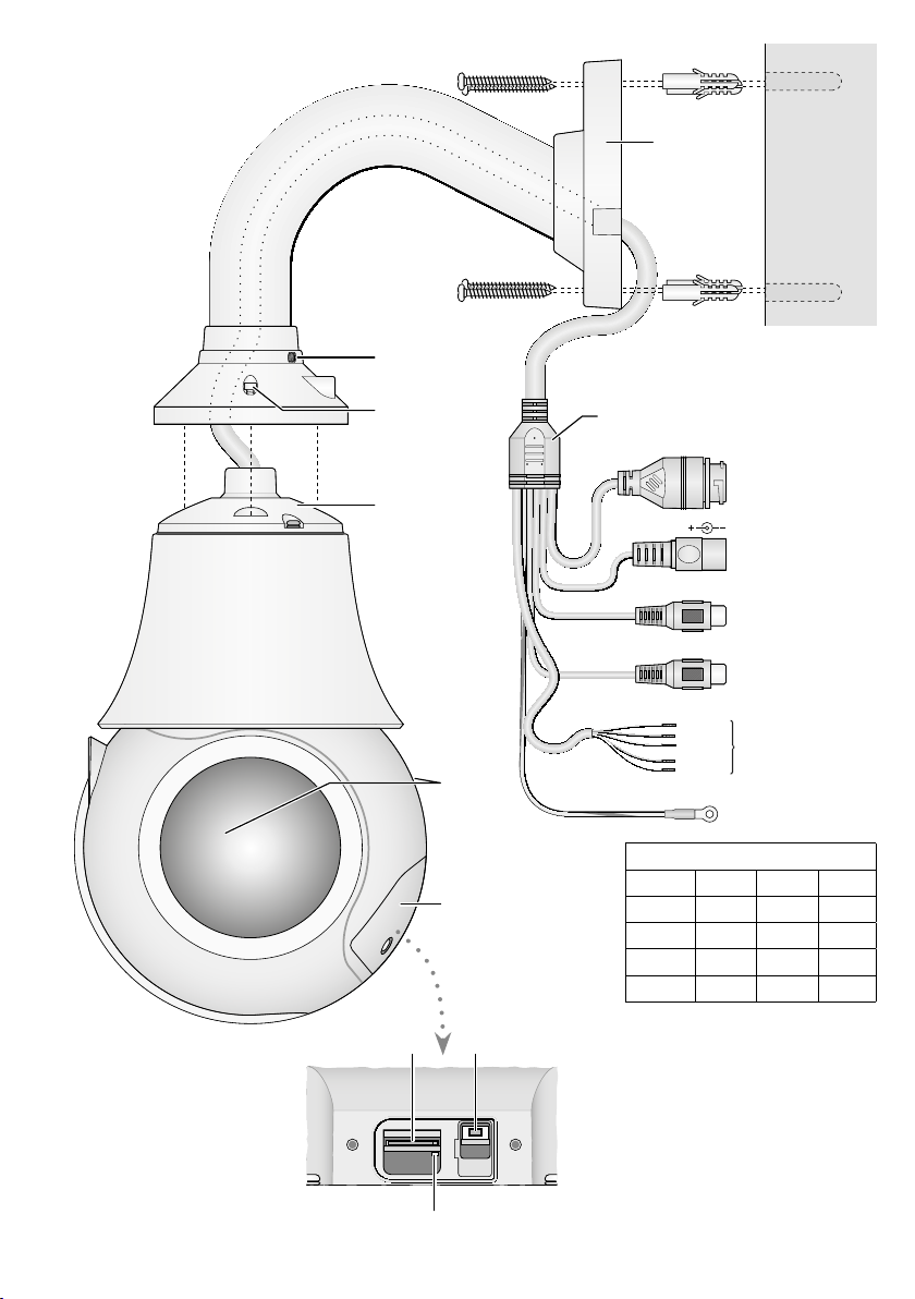
Die Anschlüsse (8 –13) und der Kabelverteiler
(7) sind nicht wetterfest. Sie müssen entspre-
Deutsch
chend geschützt werden.
1) Die Kamera über die RJ45-Kupplung (8) mit
einem einzelnen Computer, einem lokalen
Computernetzwerk oder, z. B. über einen
Router, mit größeren Computernetzwerken
(Internet) verbinden.
2) Für die Tonübertragung über das Netzwerk
kann an die Cinch-Kupplung „AudioInput“
(10) eine Tonquelle mit Line-Pegel (z. B.
Mikro fon mit Vorverstärker) angeschlossen
werden.
3) Für die Tonwiedergabe an die Cinch-Kupplung „AudioOutput“ (11) einen Kopfhörerverstärker oder eine Lautsprecher anlage
anschließen.
4)
Zur Auswertung eines Alarmgebers (z. B.
Lichtschranke) die Anschlüsse (12) IN 1 und
IN COM über einen Schließkontakt oder Öffner (in den Kamera einstellungen wählbar)
verbinden. Ein zweiter Alarmgeber kann an
die Kontakte IN 2 und IN COM angeschlossen
werden.
5)
Zum Schalten eines Gerätes, z. B. über ein
Relais, den Schaltausgang der Kamera über
die Anschlüsse (12) OUT 1 und OUT COM
anschließen. Die Schaltcharakteristik (Öffner/ Schließer, Puls) ist in den Kameraeinstellungen wählbar (☞ Kapitel 6). Der Ausgang
ist max. mit ⎓12 V/ 300 mA belastbar.
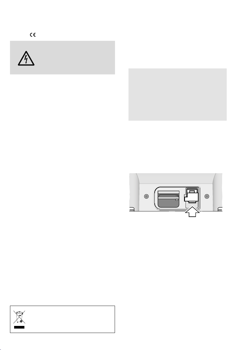
6)
Soll die Kamera eigenständig Video-Aufzeichnungen durchführen, den Deckel (1)
des Fachs auf der Rückseite des Kameragehäuses nach Lösen der beiden Schrauben öffnen und eine Speicherkarte vom
Typ „micro SD[HC/ XC]“ (max. 128 GB) einsetzen. Die Karte mit den Kontakten nach
unten zeigend in den Schlitz (14) schieben,
bis sie einrastet. Die rote LED (16) leuchtet
im Betrieb bei eingesetzter Karte. Vor dem
Entnehmen der Karte eine laufende Aufnahme unbedingt beenden! Die Karte dann
etwas hinein drücken, sodass sie ausrastet.
Den Deckel wieder dicht verschließen; der
Dichtungsring muss richtig in der Rille des
Deckels liegen.
7)
Für die Erdung des Kameragehäuses kann
das Erdungskabel (13) verwendet werden.
8)
An die Kupplung (9) das beiliegende Netzgerät oder ein anderes stabilisiertes 12-V-Netzgerät mit einer Dauerbelastbarkeit von 2 A
über einen Hohlstecker ⌀ 5,5 / 2,1 mm
(außen /innen) anschließen. Dabei die Polung beachten: Mittelkontakt = +. Das Netzkabel mit dem Netzgerät verbinden und den
Netzstecker in eine Steckdose (230 V/50 Hz)
stecken.
Alternativ lässt sich die Kamera auch über
das Netzwerkkabel versorgen (Power over
Ethernet IEEE 802.3at „PoE+“).
5 Kamera in ein Netzwerk
einbinden
Damit die Kamera zum Konfigurieren über
einen Computer direkt angesprochen werden
kann, ist ihre IP-Adresse vom Werk aus auf
192.168.0.120 voreingestellt.
Ist die aktuelle Adresse der Kamera nicht
bekannt, zum Finden der Kamera im Netzwerk
das Programm „IPSearch.exe“ starten (auf der
Monacor-Website erhältlich: www.monacor.de
Service Downloads).
1) Um die Suche zu starten, auf der Register-
karte „Multicast Search“ die Schaltfläche
„Start“ anklicken. Die im Netzwerk gefundenen Kameras werden in der Liste auf der
linken Seite angezeigt (☞Abb.4).
2)
Zum Beenden der Suche auf die Schaltfläche
„Stop“ klicken.
3) Die Kamera in der Liste auswählen. Auf der
rechten Seite werden jetzt die aktuellen Einstellungen dieser Kamera gezeigt.
4) Die Einstellungen nach Bedarf ändern:
IP-Adresse, Teilnetzmaske und GatewayAdresse können statisch festgelegt werden (Option „Device uses the following
6
Page 7
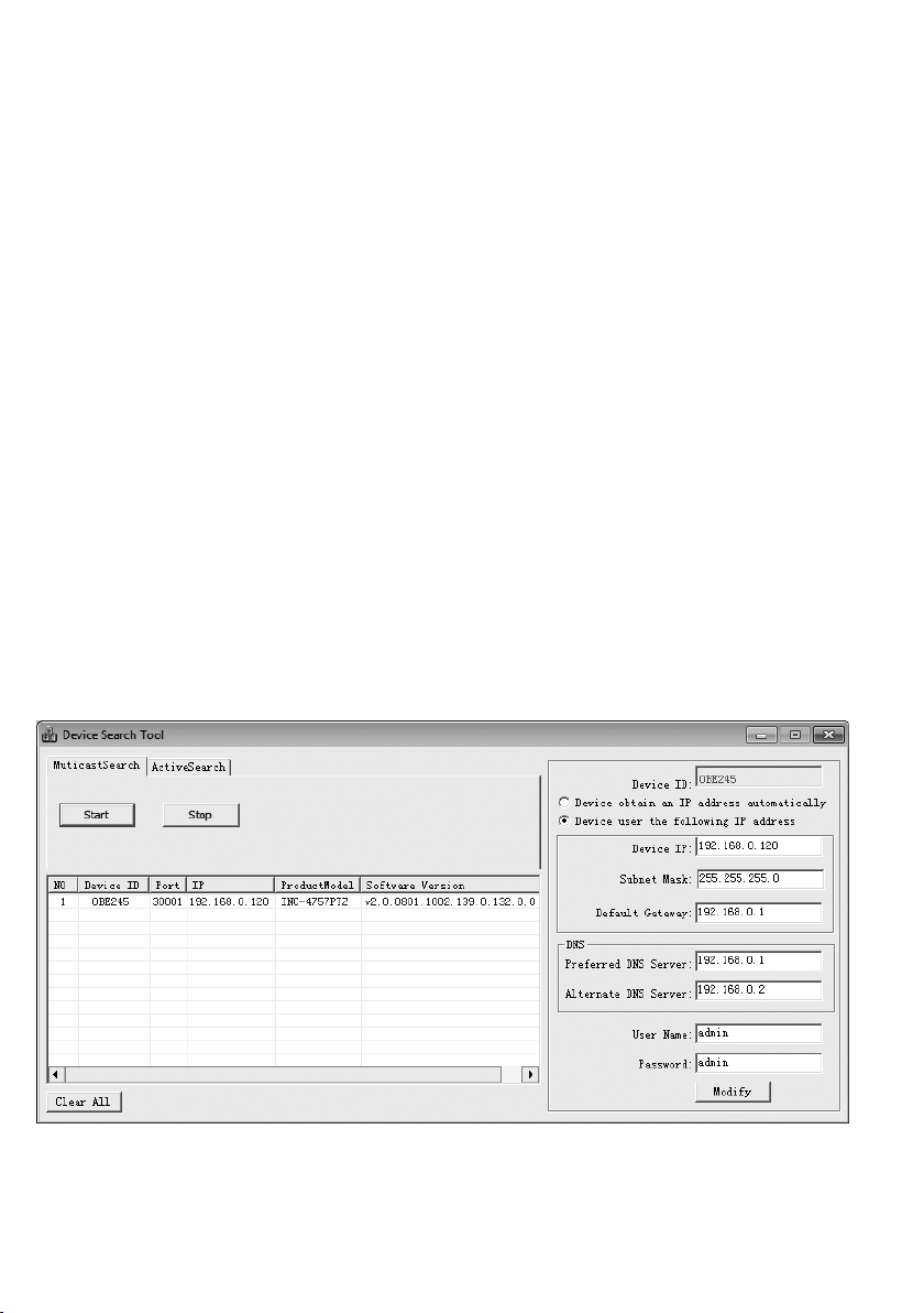
IP address“ wählen). Dabei muss für jede
Kamera eine eindeutige IP-Adresse eingegeben werden. Existiert in dem Netzwerk ein
DHCP-Server (z. B. im Router oder NetzwerkVideo rekorder), kann dieser Einstellungen für
die Kamera automatisch vornehmen (Option
„Device obtains an IP address automatically“
wählen); die automatisch vergebenen Werte
sind dann grau hinterlegt und können nicht
geändert werden.
5)
Auf die Schaltfläche „Modify“ klicken. Bei
erfolgreicher Übertragung der Änderungen
wird die Meldung „Modify success!“ angezeigt.
6)
Vor einer erneuten Suche kann die Liste über
die Schaltfläche „Clear All“ gelöscht werden.
6 Kamera über einen Computer
aufrufen
Die Bedienoberfläche der Kamera kann durch
die Eingabe ihrer IP-Adresse in der Adresszeile
des Programms Windows Internet Explorer (IE,
Version 6 oder höher) aufgerufen werden. Dazu
müssen die IP-Adressen vom Computer und der
Kamera demselben Teilnetz angehören. Es sind
max. 10 gleichzeitige Zu griffe auf die Kamera
möglich.
Beim Aufruf der Kamera erscheint zunächst
das Anmeldefenster. Hier die Sprache für die
Benutzeroberfläche wählen; die folgende Beschreibung bezieht sich auf die Einstellung
„English“. Anschließend den Benutzernamen
und das Passwort eingeben (Vorgabe für beide
Eingaben: admin). Bei einer Anmeldung mit diesen Vorgabedaten erscheint eine Aufforderung,
das Passwort zu ändern. Dies wird gegen einen
unbefugten Zugang unbedingt empfohlen.
Diese Zugangsdaten können aber auch später
in den Kameraeinstellungen geändert werden.
Ein geändertes Passwort gut merken!
Für die Nutzbarkeit aller Funktionen ist die Installation der ActiveX-Erweiterungen erforderlich. Diese werden beim erstmaligen Aufruf aus
der Kamera geladen. Wenn nötig, müssen dafür
die Sicherheitseinstellungen des IE so gelockert
werden, dass dieser Vorgang zugelassen wird.
Die Installationsdatei „NetworkSurveillance.exe“
auf dem Computer speichern, den IE schließen
und die Datei ausführen.
Windows ist ein registriertes Warenzeichen der Microsoft Corporation in den USA und anderen Ländern.
Deutsch
Suchprogramm „IPSearch“
➃
7
Page 8
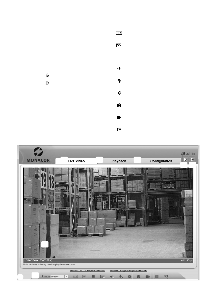
Ist die Verbindung zur Kamera aufgebaut, wird
die in Abb. 5 gezeigte Ansicht mit dem aktuellen
Kamerabild angezeigt, mit folgenden Bedienmöglichkeiten:
Deutsch
Ansicht „Live Video“ mit Anzeige des
a
Kamera bilds
Ansicht „Playback“ zur Wiedergabe der Auf-
b
nahmen aus der Kamera
Ansicht „Configuration“ zum Ändern der
c
Kameraeinstellungen
Schaltfläche zum Ändern des Passworts
d
Schaltfläche
e
Kamerabild mit Informationen zum aktuell
f
übertragenen Stream
zum Abmelden
Funktionsleiste mit folgenden Funktionen
g
/ : Beenden / Starten der Bildübertragung
„Stream“: Auswahl eines Streams
: Steuerung der Kamerabewegung und
des Objektivs (☞Kapitel6.2)
: Kameraausrichtung durch Klicken ins
Bild; Objektivzoom durch Aufziehen
eines Rahmens über dem gewünschten
Bildausschnitt
: Tonübertragung von der Kamera ein-/
ausschalten [Audio Input (10)]
: Tonübertragung zu der Kamera ein-/
ausschalten [Audio Output (11)]
: spezifische Kameraeinstellungen
(
Kapitel6.1)
☞
: Schnappschuss-Funktion zum Speichern
einer Mo mentaufnahme als Bild
: Starten / Stoppen einer Videoaufnahme
auf dem PC
: Bildanalysefunktionen ein-/ausschalten
(„Intelligent Analysis“)
a
f
g
➄
8
b
c
d
e
Page 9
Das Klicken mit rechter Maustaste auf das
Kamera bild zeigt folgendes Menü:
Menüpunkt Funktion
Full Screen (Exit
Full Screen)
Sensor
Zoom In / Out
Restore Panorama
Vollbildansicht (beenden), alternativ:
Doppelklick auf das Bild
wie
Hinein-/Herauszoomen (digital)
alternativ: mit Mausrad zoomen oder,
wenn ausgeschaltet ist, über
dem gewünschten Bildausschnitt
einen Rahmen aufziehen
gesamtes Bild zeigen (nach Zoom In)
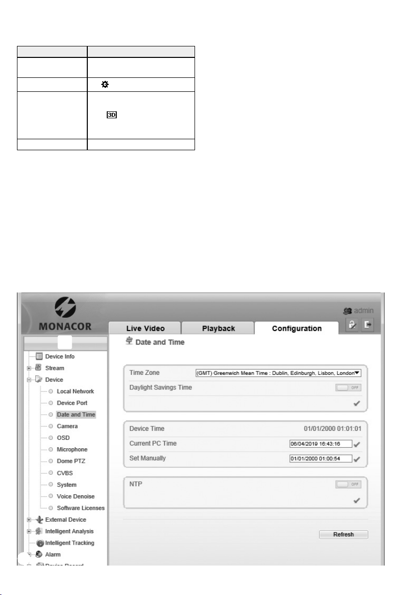
Zum Ändern der Einstellungen für die Kamera,
über den Reiter c auf die Ansicht „Configuration“ umschalten (☞Abb. 6). Am linken Rand
(h) die gewünschte Rubrik für die Einstellungen
auswählen. Durch Klicken auf ⊞ lassen sich weitere Unterrubriken anzeigen. So lässt sich z. B.
unter „Device Date and Time“ die aktuelle Zeit
für die Kamera einstellen.
Die automatische Objektverfolgung kann
über den Menüpunkt „Intelligent Tracking“
eingestellt werden.
Nach dem Ändern einer Einstellung zum
Speichern der Änderung auf den grünen
Haken✔ oder die Schaltfläche „Apply“ klicken.
Zum Laden der aktuellen Einstellungen aus der
Kamera auf die Schaltfläche „Refresh“ klicken.
Deutsch
➅
h
9
Page 10
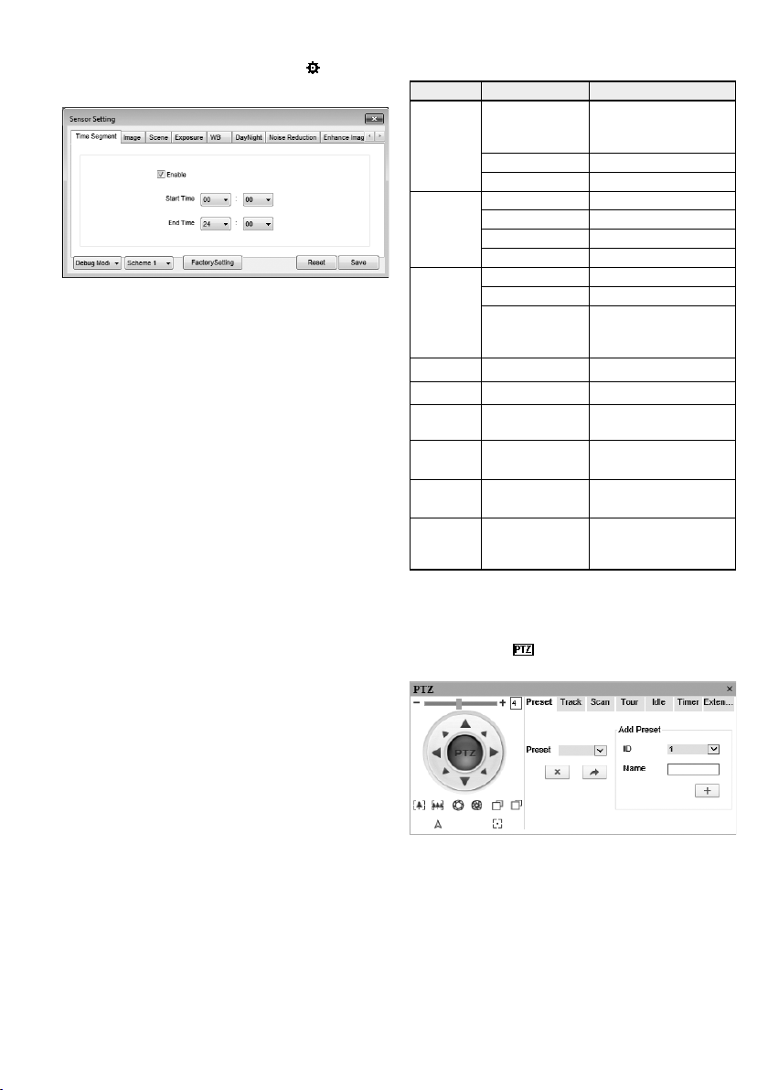
6.1 Sensor-Menü
Nach dem Klicken auf das Symbol erscheint
das Sensor-Fenster (Abb. 7).
Deutsch
Sensor-Fenster
➆
Im Listenfeld unten links kann der Modus gewählt werden. Zum Ändern der Einstellungen
den „Debug Mode“ wählen. Die im Sensor-Menü vorgenommenen Einstellungen (Ausnahme:
Zoom / Focus) lassen sich mit „Save“ als Scheme
1 – 4 speichern und wieder abrufen (Auswahl
über zweites Listenfeld). Für die gespeicherten
Einstellungen kann jeweils ein Gültigkeitszeitraum festgelegt werden (Ansicht „Time Seg
ment“). Dadurch können z. B. nachts andere
Einstellungen wirksam sein als tagsüber.
Mit „Reset“ lassen sich vorgenommene Änderungen wieder auf die gespeicherten Werte
zurücksetzen. Mit „Factory Setting“ werden die
Werkseinstellungen wiederhergestellt.
Die folgende Tabelle zeigt die Einstellmöglichkeiten des Sensor-Menüs.
Ansicht Einstellung Funktion
Time
Segment
Image
Scene
Exposure Shutter, Gain, Iris Belichtungseinstellungen
WB Mode, Red, Blue Weißabgleich
Day Night Mode, IR LED
Noise
Reduction
-
Enhance
Image
Zoom
Focus
Enable
Start Time Startzeitpunkt
End Time Endzeitpunkt
Brightness Helligkeit
Saturation Farbsättigung
Sharpness Bildschärfe
Contrast Kontrast
Scene Einsatzumgebung
Freeze Bild „einfrieren“
Mirror
3D NR Rauschunterdrückung
WDR, HLC, BLC,
Defog
Zoom, Focus,
Auto focus,
Digital Zoom
eingestellter Zeitraum
für diese Einstellungen
(Scheme) aktiv
Bildspiegelung: aus, horizontal, vertikal, horizontal
und vertikal
Tag-Nacht-Umschaltung,
Infrarot-LED-Beleuchtung
Bildoptimierung
Zoom- und Fokuseinstellungen
6.2 PTZ-Steuerung
Zur Steuerung der Kamerabewegung und des
Objektivs über das PTZ-Fenster (Abb. 8) aufrufen.
10
PTZ-Fenster
➇
Über die im Kreis angeordneten Pfeile lässt sich
die Kamerabewegung steuern. Mit dem Regler
darüber wird die Bewegungsgeschwindigkeit
bestimmt. Folgende Funktionen zur Steuerung
des Objektivs sind verfügbar:
Page 11

: hineinzoomen : herauszoomen
: Blende öffnen : Blende schließen
: Fokus näher : Fokus ferner
: automatisch fokussieren
6.2.1 Speichermöglichkeiten
In der Kamera können zahlreiche Positionen
und Bewegungsmuster gespeichert werden.
Die folgenden vier Speicherarten werden unterschieden:
Preset: gespeicherte Position und Objektivein-
stellung
Track: Aufzeichnung von durchgeführten Be-
wegungen und Einstellungen
Scan: Automatisches Pendeln zwischen zwei
festgelegten Positionen/Objektiveinstellungen
Tour: festgelegte Folge zuvor gespeicherter
Presets
Diese lassen sich manuell aufrufen oder bei
einem Neustart der Kamera oder nach einer
einstellbaren Phase der Inaktivität automatisch
starten.
Ansicht Funktion
Preset speichern („Add Preset“)
1� Position und Objektiv einstellen
2� gewünschten Preset-Namen „Name“ eingeben
3� mit speichern
Preset
Track
Preset abrufen
1� Preset wählen
2� mit bestätigen
Preset löschen
1� Preset wählen
2� mit bestätigen
Track aufzeichnen („Add Track“)
1� gewünschten Track-Namen „Name“ eingeben
2� Aufnahme mit starten
3� Bewegungen/Objektiveinstellungen durchführen
4� Aufnahme mit beenden
Track starten
1� Track wählen
2� mit bestätigen*
Track löschen
1� Track wählen
2� mit bestätigen
Ansicht Funktion
Scan speichern („Add Scan“)
1� gewünschten Scan-Namen „Name“ eingeben
2� Position und Objektiv einstellen
3� erste Einstellung mit speichern
4� Position und Objektiv einstellen
Scan
Tour
Idle
Timer
Extension
* Abbruch bei Durchführen von Bewegungen und
5� zweite Einstellung mit speichern
Scan starten
1� Scan wählen
2� mit bestätigen*
Scan löschen
1� Scan wählen
2� mit bestätigen
Tour speichern („Add Tour“)
1� gewünschten Tour-Namen „Name“ eingeben
2� Programmierung mit starten
3� (zuvor gespeichertes) Preset wählen
4� Verweildauer „Wait Time“ für das Preset
festlegen [s]
5� Programmschritt mit ✔ speichern
Bedienschritte 3�– 5� für weitere Presets wiederholen
6� Programmierung mit beenden
Tour starten
1� Tour wählen
2� mit bestätigen*
Tour löschen
1� Tour wählen
2� mit bestätigen
automatische Aktion nach inaktiver Phase
1� Funktion mit „Enable = ON“ einschalten
2� unter „PTZ Type“ die Art der Aktion (Preset /
Scan / Track / Tour) wählen
3� unter „Name“ den Namen der (zuvor gespeicher-
ten) Aktion wählen
4� unter „Wait Time“ die Dauer der Inaktivität [min]
angeben, nach der die Aktion startet
5� Einstellungen mit ✔ speichern
zeitgesteuerte Aktionen
1� Funktion mit „Enable“ einschalten
2� „Timer Mode“ wählen:
täglich „Everyday“oder einmalig „Once“
3� Aktionszeitraum einstellen;
bei „Timer Mode =Once“ unter „Time“ das
Datum wählen
4� unter „PTZ Type“ die Art der Aktion (Preset /
Scan / Track / Tour) wählen
5� unter „Name“ den Namen der (zuvor gespeicher-
ten) Aktion wählen
Bedienschritte 3�– 5� für weitere Aktionen wiederholen
6� Aktion bei Bedarf mit löschen
7� Einstellungen mit ✔ speichern
Reboot Action
automatische Aktion nach einem Neustart, einzustellen wie bei „Idle“
Einstellungen oder bei Aufruf anderer gespeicherter
Presets / Tracks / Scans / Touren
Deutsch
11
Page 12

7 Zurücksetzen der Kamera
Die Kamera kann auf ihre Werkseinstellungen
zurückgesetzt werden. Dabei gehen alle vom
Anwender durchgeführten Änderungen der
Deutsch
Kameraeinstellungen verloren.
1) Den Deckel (1) des Fachs auf der Rückseite
des Kameragehäuses nach Lösen der beiden
Schrauben öffnen.
2) Den Reset-Taster (15) länger als 5 Sekunden
drücken (☞ Abb. 2). Der Rücksetzprozess
startet nach dem Loslassen der Taste verzögert und kann einige Minuten dauern.
3)
Den Deckel wieder dicht verschließen; der
Dichtungsring muss richtig in der Rille des
Deckels liegen.
Die Kamera ist jetzt wieder auf die statische
IP-Adresse 192.168.0.120 eingestellt, der Benutzername und das Kennwort für die Anmeldung
lauten: admin
8 Technische Daten
Bildabtaster: � � � � � � � � � � �CMOS, 9,07 mm (⁄”)
� � � � � � � � � � � � � �4,7 – 56,4 mm / 1 : 1,6 – 3,5
Objektiv:
Motor-Zoom
Blickwinkel:
Schwenkwinkel: � � � � � � � � �360° (endlos)
Geschwindigkeit: � � � � � � 0,1°/s bis 180°/s
Neigewinkel:
Geschwindigkeit: � � � � � � 0,1°/s bis 90°/s
PTZ-Speicher
Presets: � � � � � � � � � � � � � 300
Touren: � � � � � � � � � � � � � � 12
Scans: � � � � � � � � � � � � � � � 12
Tracks: � � � � � � � � � � � � � � 6
Mindestbeleuchtung:
IR-LED-Reichweite: � � � � � �100 m
Auflösung: � � � � � � � � � � � �max� 25 Bilder / s bei
Elektronischer Verschluss:
Protokolle: � � � � � � � � � � � � �IPv4, IPv6, HTTPS,
Kompressionsverfahren: � � �H�264, H�265, MJPEG
Videostreaming
Mainstream: � � � � � � � � � �500 –12 000 kbit /s
Substream 1: � � � � � � � � �100 – 6 000 kbit /s
Substream 2: � � � � � � � � �100 – 3 000 kbit /s
Audioformate: � � � � � � � � � � G�711, RAW-PCM
Netzwerk: � � � � � � � � � � � � �Ethernet 10 / 100 MBit / s
Einsatztemperatur:� � � � � � �−40 °C bis +60 °C
Schutzart: � � � � � � � � � � � � �IP 66
Stromversorgung: � � � � � � �⎓12 V/2 A, max� 22 W
Kamera-Abmessungen: � � � ⌀146 mm × 220 mm
Gewicht: � � � � � � � � � � � � � � 1,5 kg
� � � � � � � � � � � � 8° bis 70°
� � � � � � � � � � �−10° bis +90°
� � � � �0,01 lx (Farbe)
2048 × 1536 Bildpunkten
�⁄ – ⁄ s
RTSP, DDNS, SMTP, SSL,
ONVIFv17�06 u� a�
oder Power over Ethernet
IEEE802�3at „PoE+“
Änderungen vorbehalten.
Diese Bedienungsanleitung ist urheberrechtlich für MONACOR ® INTERNATIONAL GmbH & Co. KG geschützt.
Eine Reproduktion für eigene kommerzielle Zwecke – auch auszugsweise – ist untersagt.
12
Page 13

13
Page 14

Outdoor PTZ Network Camera
These instructions are intended for installers of
video surveillance systems. Please read the in-
English
structions carefully prior to installation and keep
them for later reference.
All mounting components and connections
described can be found on page 2.
Contents
1 Applications � � � � � � � � � � � � � � � � 14
2 Safety Notes � � � � � � � � � � � � � � � � 15
3 Installation� � � � � � � � � � � � � � � � � 15
4 Connecting the Camera� � � � � � � � � � 16
5 Connecting the Camera toaNetwork� � 16
6 Calling up the Camera viaComputer � � 17
6�1 Sensor menu � � � � � � � � � � � � � � � � � 20
6�2 PTZ control� � � � � � � � � � � � � � � � � � 20
6�2�1 Storage options � � � � � � � � � � � � � � 21
7 Resetting the Camera� � � � � � � � � � � 22
8 Specifications � � � � � � � � � � � � � � � 22
1 Applications
The camera INC-4757PTZ is specially designed
for video surveillance systems based on computer networks. Its housing is weatherproof;
therefore, the camera is also suited for outdoor
applications. It is equipped with a 3 megapixel
image sensor and a zoom lens with autofocus
and iris control. The camera features include mirror image, masking of image areas and image
analysis functions (e. g. motion detection). The
camera supports auto-tracking, i. e. it is able to
track moving objects automatically. In the dark,
the integrated IR LEDs will illuminate a surveillance zone of up to 100 m and the camera will
switch to B / W mode. The camera is provided
with an integrated web server with 3-way video
streaming. For correct configuration, knowledge
of network technology is indispensable.
The camera can be operated in combination
with a network video recorder (e. g. NWR-…*)
or operated independently via web browser. The
camera movements (pan and tilt) and the lens
(zoom, iris and focus) can be controlled via web
browser or via a recorder from the NWR series.
The camera is equipped with an audio input
and an audio output so that mutual communication via computer will be possible. A switching output is provided for switching devices,
e. g. triggered by integrated motion detection.
The camera also offers two alarm inputs. These
inputs can be used, for example, to start recordings or e-mail messages. A memory card slot
allows video recording in the camera according
to schedule or triggered by an image analysis
function.
*Hint: If this camera model does not appear in the list
of the recorder used, select the ONVIF protocol.
14
Page 15

2 Safety Notes
The units (camera and power supply unit) correspond to all relevant directives of the EU and
are therefore marked with
WARNING
Protect the camera against extreme tempera-
•
tures (admissible ambient temperature range:
−40 °C to +60 °C).
The power supply unit is suitable for indoor
•
use only. Protect it against dripping water,
splash water and high air humidity. The admissible ambient temperature range is 0 – 40 °C.
Do not operate the units and immediately
•
disconnect the power supply unit from the
mains socket
1.
if one of the units or the mains cable is
visibly damaged,
2. if a defect might have occurred after a unit
was dropped or suffered a similar accident,
3. if malfunctions occur.
In any case, the units must be repaired by
skilled personnel.
Never pull the mains cable to disconnect the
•
mains plug from the socket, always seize the
plug.
For cleaning the power supply unit, only use a
•
dry, soft cloth; never use water or chemicals.
For cleaning the camera, the cloth may be
slightly wet and a mild detergent may be used.
No guarantee claims for the units and no li-
•
ability for any resulting personal damage or
material damage will be accepted if the units
are used for other purposes than originally
intended, if they are not correctly connected or operated, or if they are not repaired in
an expert way. Likewise, no liability will be
accepted for any data loss due to operating
errors or a defect or for any consequential
damage caused by this data loss.
The power supply unit uses dangerous mains voltage. Leave servicing to skilled personnel only.
Inexpert handling may result in
electric shock.
If the units are to be put out of operation definitively, take them to a local
recycling plant for a disposal which is
not harmful to the environment.
.
3 Installation
1)
A test operation is recommended in order
to find the best mounting location. For this
purpose, operate the camera temporarily (☞next chapters). To avoid scratches,
leave the protective film on the dome during
installation (gloves are provided).
CAUTION When it gets dark, the infrared
LEDs (2) will switch on. When setting up the
camera, never look directly into the lit infrared LEDs at close range. The infrared light
may cause eye irritation. However, the infrared radiation is far below the emission limit
and rated risk-free according to EN 62471.
2)
Release the two screws and open the
cover(1) of the compartment on the rear
of the camera housing. Remove the transport lock (☞arrow in fig. 3) of the camera.
Close the cover. Also remove the adhesive
tape used for fixing the movable part of the
camera.
Transport lock
➂
3)
At the mounting location, drill four holes
for fixing the mounting plate (6) of the wall
bracket and, if necessary, drill a hole for the
connection cable (alternatively, guide the
cable through one of the knock-out holes
on the side or underneath the camera base).
A drilling jig is provided. Use the dowels provided, if required.
4) Guide the cable of the camera through the
tube of the wall bracket. Use the three hexagon socket screws (4) to fasten the bracket
to the upper side of the camera. Fasten the
locking screw (5) to keep the camera in this
position.
5) Use the four long recessed head screws to
attach the wall bracket to the mounting
location.
English
15
Page 16

4 Connecting the Camera
The connections (8 – 13) and the cable splitter(7) are not weatherproof; protect them
English
accordingly.
1) Connect the camera via the RJ45 connector
(8) to an individual computer, a local computer network or, e. g. via a router, to larger
computer networks (Internet).
2)
For audio transmission via the network,
connect an audio source with line level (e. g.
microphone with preamplifier) to the RCA
connector “Audio Input” (10).
3)
For audio reproduction, connect a headphone amplifier or a sound system to the
RCA connector “Audio Output” (11).
4) To evaluate an alarm device (e. g. photoelectric sensor), connect the pins (12) IN 1 and IN
COM via a normally open contact or normally
closed contact (to be selected in the camera settings). A second alarm device can be
connected to the contacts IN 2 and IN COM.
5) To switch a device (e. g. via a relay), connect
the switching output of the camera via the
pins (12) OUT 1 and OUT COM. Select the
switching characteristic (normally open contact/normally closed contact, pulse) in the
camera settings (☞ chapter 6). The maximum load of the output is ⎓12 V/ 300 mA.
6)
For independent video recordings of the
camera, release the two screws, open the
cover(1) of the compartment on the rear
of the camera housing and insert a memory
card of the type “microSD[HC / XC]” (128 GB
max.). Push the card (contacts to the bottom)
into the slot (14) until it engages. The red
LED (16) will light up during operation when
a card has been inserted. Never remove the
card while a recording is being made! To remove the card, push the card into the slot
until it disengages. Tightly close the cover
again. Make sure that the gasket is correctly
positioned in the groove of the cover.
7)
To ground the camera housing, a ground
cable (13) is provided.
8) Connect the power supply unit provided or
another regulated 12 V power supply unit
with a permanent rating of 2 A via a DC
power connector ⌀ 5.5 / 2.1 mm (outside /
inside) to the connector (9). Always observe
the correct polarity: centre contact = +. Connect the mains cable to the power supply unit
and to a mains socket (230 V/ 50 Hz).
Alternatively, use the network cable
(Power over Ethernet IEEE 802.3at “PoE+”)
to supply the camera with power.
5 Connecting the Camera
toaNetwork
To be able to directly address the camera for
configuration via computer, its IP address is factory-set to 192.168.0.120.
If you do not know the current address of
the camera, start the program “IPSearch.exe”
(available on the Monacor homepage: www.
monacor.com Support Downloads) to find
the camera in the network.
1) To start the search, click the button “Start”
of the tab “Multicast Search”. The list on
the left will show the cameras found in the
network (
2) To stop the search, click the button “Stop”.
3) Select the camera from the list. The current
settings of this camera can be found on the
right.
4) Change the settings as required:
IP address, subnet mask and gateway address
can be defined as static values (select the option “Device uses the following IP address”).
Enter a unique IP address for each camera.
If a DHCP server is available in the network
(e. g. in the router or network video recorder),
this server will be able to automatically make
settings for the camera (select the option
“Device obtains an IP address automatically”). The values assigned automatically are
highlighted in grey and cannot be changed.
5) Click the button “Modify”. After successful
transmission of the modifications, the message “Modify success!” will appear.
6) Before you start a new search, click the but-
ton “Clear All” to delete the list.
☞
fig. 4).
16
Page 17

6 Calling up the Camera
viaComputer
To call up the user interface of the camera, enter
its IP address in the address bar of the program
Windows Internet Explorer (IE, version 6 or higher). The IP addresses of the computer and of
the camera must be in the same subnet. The
number of simultaneous accesses to the camera
is limited to 10.
When the camera is called up, the log-in
window will appear. Select the language for the
user interface. The description below refers to
English. Then enter the user name and the password (default setting for both: admin). If you
use the default password, a request to change
the password will appear. It is recommended to
change the password to prevent unauthorized
access. Individual log-in data can also be defined
later in the camera settings. If you change the
password, make sure to remember it!
To make all functions available, installation of
the ActiveX extensions is required. These extensions will be loaded from the camera when
the camera is called up for the first time. If
necessary, reduce the security settings of the
IE accordingly to allow the installation process.
Save the installation file “NetworkSurveillance.
exe” to the computer, close the IE and execute
the file.
Windows is a registered trademark of Microsoft Corporation in the
USA and other countries.
English
Search program “IPSearch”
➃
17
Page 18

When the connection to the camera has been
established, the view with the current camera
image (fig. 5) will be displayed. The following
English
options are available:
View “Live Video” with display of camera
a
image
View “Playback” to replay the recordings
b
from the camera
View “Configuration” to change the camera
c
settings
Button to change the password
d
Button to log out
e
Camera image with information on the
f
stream currently transmitted
Toolbar with the following functions:
g
/ : Stop/Start of image transmission
“Stream”: Selection of a stream
: Control of camera movement and lens
(☞ chapter 6.2)
: Camera alignment when clicking on the
image; lens zoom when dragging the
mouse to select the desired image section
: Activation/Deactivation of audio transmis-
sion from the camera [Audio Input (10)]
: Activation/Deactivation of audio transmis-
sion to the camera [Audio Output (11)]
: Specific camera settings (☞ chapter 6.1)
: Snapshot function to save a snapshot as
an image file
: Starting / Stopping a video recording on
the PC
: Activation/Deactivation of image analysis
functions (“Intelligent Analysis”)
18
➄
g
f
a
b
c
d
e
Page 19

When the camera image is clicked with the right
mouse button, the following menu will appear:
Menu item Function
Full Screen (Exit
Full Screen)
Sensor
Zoom In / Out
Restore Panorama
full-screen image (exit), alternatively:
double-click the image
like
zooming in / zooming out (digital)
alternatively: use the scroll wheel to
zoom in/out or, when has been
deactivated, drag the mouse to select
the desired image section
display of the entire image
(after zooming in)
To change the settings for the camera, select
the tab c and go to the view “Configuration”(☞fig. 6). On the left (h), select the desired category for the settings. To show additional subcategories, click ⊞. To set, for example,
the current time for the camera, go to “Device
Date and Time”.
For auto-tracking of objects, go to the menu
item “Intelligent Tracking”.
To save a setting that has been changed,
click the green check mark ✔ or the button
“Apply”. To load the current settings from the
camera, click the button “Refresh”.
English
➅
h
19
Page 20

6.1 Sensor menu
To activate the sensor menu (fig. 7), click the
icon .
English
Sensor menu
➆
Select the mode in the list field at the bottom on
the left. To change the settings, select “Debug
Mode”. The settings made in the sensor menu
(exception: Zoom/Focus) can be saved with
“Save” (Schemes 1 – 4) and retrieved (selection
via second list field). It is possible to define an
individual validity period for each of the settings
saved (view “Time Segment”). This will allow
you, for example, to make different settings for
day and night.
To reset the settings to the values saved,
click “Reset”. To reset the settings to the factory
settings, click “Factory Setting”.
The setup options of the sensor menu can be
found in the table below.
View Setting Function
Time
Segment
Image
Scene
Exposure Shutter, Gain, Iris exposure settings
WB Mode, Red, Blue white balance
Day Night Mode, IR LED
Noise
Reduction
Enhance
Image
Zoom
Focus
Enable
Start Time start of validity period
End Time end of validity period
Brightness brightness
Saturation saturation
Sharpness sharpness
Contrast contrast
Scene place of application
Freeze “freezing” an image
Mirror
3D NR noise reduction
WDR, HLC, BLC,
Defog
Zoom, Focus,
Auto focus,
Digital Zoom
activation of the validity
period defined for these
settings (Scheme)
mirror image: off, horizontal, vertical, horizontal and
vertical
day / night switching,
infrared LED illumination
image enhancement
zoom and focus settings
20
6.2 PTZ control
To control the camera movements and the lens,
click to activate the PTZ window (fig. 8).
PTZ window
➇
The camera movements are controlled by means
of the arrows arranged in a circle. The control
above the circle is used to define the speed of
movements. The following functions are available to control the lens:
Page 21

: zooming in : zooming out
: open iris : close iris
: focus near : focus far
: autofocus
6.2.1 Storage options
Numerous positions and patterns of movement
can be saved to the camera. There are four different options:
Preset: position and lens setting saved
Track: recording of movements and lens set-
tings performed
Scan: automatic alternation between two
positions / lens settings that have been
defined
Tour: fixed sequence of presets saved previ-
ously
These actions can be retrieved manually or start
ed automatically when the camera is restarted
or after a phase of inactivity.
View Function
To save a preset (“Add Preset”):
1� Set the position and the lens�
2� Enter the preset name desired (“Name”)�
3� Click to save�
Preset
Track
To retrieve a preset:
1� Select a preset�
2� Click to confirm�
To delete a preset:
1� Select a preset�
2� Click to confirm�
To record a track (“Add Track”):
1� Enter the track name desired (“Name”)�
2� Click to start the recording�
3� Make the settings for movement and lens�
4� Click to stop the recording�
To start a track:
1� Select a track�
2� Click to confirm�*
To delete a track:
1� Select a track�
2� Click to confirm�
View Function
To save a scan (“Add Scan”):
1� Enter the scan name desired (“Name”)�
2� Set the position and the lens�
3� Click to save the first setting�
4� Set the position and the lens�
Scan
Tour
Idle
Timer
Extension
* will be cancelled when movements or settings are
5� Click to save the second setting�
To start a scan:
1� Select a scan�
2� Click to confirm�*
To delete a scan:
1� Select a scan�
2� Click to confirm�
To save a tour (“Add Tour”):
1� Enter the tour name desired (“Name”)�
2� Click to start programming�
3� Select a preset (saved previously)�
4� Define the “Wait Time” for the preset [s]�
5� Click ✔ to save the step�
Repeat steps 3�– 5� for additional presets�
6� Click to stop programming�
To start a tour:
1� Select a tour�
2� Click to confirm�*
To delete a tour:
1� Select a tour�
2� Click to confirm�
Automatic action after a phase of inactivity:
1� Activate the function with “Enable = ON”�
2� Use “PTZ Type” to select the type of action
(Preset /Scan / Track / Tour)�
3� Use “Name” to select the name of the action
(saved previously)�
4� Use “Wait Time” to define the phase of inactivity
[min] after which the action will start�
5� Click ✔ to save the settings�
Time-controlled actions:
1� Click “Enable” to activate the function�
2� Select the “Timer Mode”:
“Everyday” or “Once”
3� Set the action time;
for “Timer Mode = Once”, use “Time” to select
the date
4� Use “PTZ Type” to select the type of action
(Preset /Scan / Track / Tour)�
5� Use “Name” to select the name of the action
(saved previously)�
Repeat steps 3�– 5� for additional actions�
6� Delete the action (), if required�
7� Click ✔ to save the settings�
Reboot Action
automatic action after restart, settings identical to
“Idle”
made or when other presets / tracks / scans / tours that
have been saved are retrieved
English
21
Page 22

7 Resetting the Camera
When the camera is reset to its factory settings,
any changes the user has made to the camera
English
settings will be lost.
1) Release the two screws and open the cover
(1) of the compartment on the rear of the
camera housing.
2) Keep the Reset button (15) pressed for more
than 5 seconds (☞ fig. 2). When the button
is released, resetting will start with a delay
and may take a few minutes.
3)
Tightly close the cover again. Make sure
that the gasket is correctly positioned in the
groove of the cover.
The camera is reset to the static IP address
192.168.0.120. The default user name and the
password for log-in is: admin
8 Specifications
Image sensor: � � � � � � � � � � CMOS, 9�07 mm (⁄”)
� � � � � � � � � � � � � � � � � 4�7 – 56�4 mm / 1 : 1�6 – 3�5
Lens:
motor zoom
Viewing angle:
� � � � � � � � � � � � � � � � �360° (endless)
Pan:
Speed: � � � � � � � � � � � � � � 0�1°/s to 180°/s
Tilt: � � � � � � � � � � � � � � � � � � −10° to +90°
Speed: � � � � � � � � � � � � � � 0�1°/s to 90°/s
PTZ memory
Presets: � � � � � � � � � � � � � 300
Tours: � � � � � � � � � � � � � � �12
Scans: � � � � � � � � � � � � � � � 12
Tracks: � � � � � � � � � � � � � � 6
Minimum illumination:
IR LED range: � � � � � � � � � � 100 m
Resolution: � � � � � � � � � � � � 25 frames max�
Electronic shutter:
Protocols: � � � � � � � � � � � � � IPv4, IPv6, HTTPS, RTSP,
Compression: � � � � � � � � � � H�264, H�265, MJPEG
Video streaming
Mainstream: � � � � � � � � � �500 –12 000 kbit /s
Substream 1: � � � � � � � � �100 – 6 000 kbit /s
Substream 2: � � � � � � � � �100 – 3 000 kbit /s
Audio formats: � � � � � � � � � G�711, RAW-PCM
Network: � � � � � � � � � � � � � �Ethernet 10 / 100 MBit / s
Ambient temperature: � � � �−40 °C to +60 °C
IP rating: � � � � � � � � � � � � � � IP 66
Power supply:
Camera dimensions: � � � � �⌀146 mm × 220 mm
Weight: � � � � � � � � � � � � � � � 1�5 kg
� � � � � � � � �8° to 70°
� � � �0�01 lx (colour)
per second with
2048 × 1536 pixels
� � � � � � �⁄ – ⁄ s
DDNS, SMTP, SSL,
ONVIF v17�06, etc�
� � � � � � � � � �⎓12 V/2 A, 22 W max�
or Power over Ethernet
IEEE 802�3at “PoE+”
Subject to technical modification.
All rights reserved by MONACOR ® INTERNATIONAL GmbH & Co. KG. No part of this instruction manual may
be reproduced in any form or by any means for any commercial use.
22
Page 23

23
Page 24

Caméra extérieure PTZ réseau
Cette notice s’adresse aux installateurs de systèmes de surveillance vidéo. Veuillez lire la présente notice avec attention avant l’installation
Français
et conservez-la pour pouvoir vous y reporter
ultérieurement.
Vous trouverez sur la page 2 les éléments de
montage et les branchements décrits.
Table des matières
1 Possibilités d’utilisation � � � � � � � � � 24
2 Conseils desécurité� � � � � � � � � � � � 25
3 Montage � � � � � � � � � � � � � � � � � � 25
4 Branchement de la caméra � � � � � � � � 26
5 Intégrer la caméra dans unréseau � � � 26
6 Appeler la caméra via unordinateur � � 27
6�1 Menu capteur – Sensor – � � � � � � � � � � 30
6�2 Gestion PTZ � � � � � � � � � � � � � � � � � 30
6�2�1 Possibilités de mémorisation � � � � � � � � 31
7 Réinitialisation de la caméra� � � � � � � 32
8 Caractéristiques techniques � � � � � � � 32
1 Possibilités d’utilisation
La caméra INC-4757PTZ est spécialement
conçue pour une utilisation dans des installations de surveillance vidéo basée sur des réseaux
informatiques. Grâce à son boîtier étanche,
elle est également adaptée à une utilisation en
extérieur. Elle est dotée d’un capteur d’image
3mégapixels et d’un objectif zoom avec fonction autofocus et diaphragme géré et propose
entre autres, une visualisation en image miroir,
un masquage de zones d’images et des fonctions d’analyse d’image (p. ex. une détection de
mouvements). Avec la fonction Autotracking,
la caméra peut automatiquement suivre des
objets en mouvement. Dans la pénombre, les
LEDs infrarouges intégrées éclairent la zone de
surveillance jusqu’à 100 m ; la caméra commute
automatiquement en mode noir et blanc. La
caméra dispose d’un serveur web intégré avec
streaming vidéo × 3. Pour une installation correcte, des connaissances en technologie réseau
sont indispensables.
La caméra peut être utilisée, combinée
à un enregistreur vidéo réseau (par exemple
NWR-…*) ou seule avec un navigateur web. La
gestion du mouvement de la caméra (inclinaison
et rotation) et de l’objectif (zoom, diaphragme et
focus) peut se faire via le navigateur web ou un
enregistreur de la série NWR. La caméra dispose
d’une entrée audio et d’une sortie audio pour
qu’une communication réciproque via un ordinateur soit possible. Une sortie de commutation
permet de commuter des appareils, par exemple
déclenchée par la détection de mouvements
intégrée. En plus, la caméra dispose de deux
entrées d’alarme, via lesquelles par exemple
un enregistrement ou une communication par
email peut être démarré. Une fente pour carte
mémoire permet un enregistrement vidéo dans
la caméra, selon un planning ou déclenché par
une fonction d’analyse d’image.
* Conseil : Si le modèle de caméra n’existe pas dans la
liste de l’enregistreur utilisé, sélectionnez le
protocole ONVIF.
24
Page 25

2 Conseils desécurité
Les appareils (caméra et bloc secteur) répondent
à toutes les directives nécessaires de l’Union
européenne et portent donc le symbole .
AVERTISSEMENT Le bloc secteur est alimenté
par une tension dangereuse.
Ne touchez jamais l’intérieur
de l’appareil, il y a risque de
décharge électrique.
Protégez la caméra des températures ex-
•
trêmes (plage de température de fonctionnement autorisée : −40 °C à +60 °C).
Le bloc secteur ne doit être utilisé qu’en inté-
•
rieur ; protégez-le de tout type de projections
d’eau, des éclaboussures et d’une humidité
élevée de l’air. La plage de température de
fonctionnement autoriséeest de 0 – 40 °C.
Ne faites pas fonctionner les appareils et dé-
•
branchez le bloc secteur immédiatement dans
les cas suivants :
1. un des apapreils ou le cordon secteur présente des dommages visibles.
2. après une chute ou un accident similaire,
vous avez un doute sur l’état de l’appareil.
3. des dysfonctionnements apparaissent.
Dans tous les cas, les dommages doivent être
réparés par un technicien spécialisé.
Ne débranchez jamais l’appareil en tirant sur
•
le cordon secteur ; retirez toujours le cordon
secteur en tirant la fiche.
Pour nettoyer le bloc secteur, utilisez unique-
•
ment un tissu sec et doux, en aucun cas de
produits chimiques ou d’eau. La caméra peut
également être nettoyée avec un tissu humide
et un produit de nettoyage doux.
Nous déclinons toute responsabilité en cas de
•
dommages corporels ou matériels résultants
si les appareils sont utilisés dans un but autre
que celui pour lequel ils ont été conçus, s’ils
ne sont pas correctement branchés ou utilisés
ou s’ils ne sont pas réparés par une personne
habilitée; en outre, la garantie deviendrait
caduque. De même, notre responsabilité ne
saurait être engagée en cas de pertes de données et leurs conséquences, causées par une
mauvaise utilisation ou un défaut.
Lorsque les appareils sont définitivement retirés du service, vous devez les
déposer dans une usine de recyclage de
proximité pour contribuer à leur élimination non polluante.
CARTONS ET EMBALLAGE
PAPIER À TRIER
3 Montage
1)
Un test de fonctionnement doit être effectué
afin de définir le lieu optimal de montage.
Pour ce faire, mettez temporairement la
caméra en fonction (☞chapitre suivant).
Pour éviter toute rayure pendant le montage,
laissez la feuille de protection sur le dôme
(gants livrés).
ATTENTION Les LEDs infrarouges (2) s’allument dans la pénombre. Lors de l’installation de la caméra, ne regardez jamais
directement les LEDs allumées de proximité.
La lumière infrarouge peut engendrer des
irritations des yeux. Le rayonnement infrarouge est cependant bien en dessous du
seuil limite d’émission et classé sans risque
selon la norme EN 62471.
2) Ouvrez le couvercle (1) du compartiment sur
la face arrière du boîtier de la caméra après
avoir desserré les deux vis et retirez la sécurité
de transport (☞flèche sur le schéma 3) de
la caméra. Refermez le couvercle. De même
retirez les bandes adhésives de la partie
mobile de la caméra.
Sécurité de transport
➂
3) Sur le lieu de montage, percez quatre trous
pour fixer la plaque de montage (6) du support mural et si besoin, percez un trou pour
le câble de branchement (le câble peut également passer via un des passages sur le côté
du socle ou sous le socle). Un gabarit est livré.
Si besoin, utilisez les chevilles livrées.
25
Page 26

4) Faites passer le câble de la caméra via le perçage du support mural et fixez le support
avec les trois vis à pans creux (4) sur la face
supérieure de la caméra. Avec la vis (5), sécu-
Français
risez la caméra pour éviter qu’elle ne tourne.
5)
Fixez le support mural avec les quatre longues
vis cruciformes sur le lieu de montage.
4 Branchement de la caméra
Les connexions (8 –13) et le répartiteur de câble
(7) ne sont pas étanches. Vous devez les protéger
en conséquence.
1)
Reliez la caméra via la prise RJ45 (8) à un
ordinateur individuel, un réseau local d’ordinateurs ou, par exemple via un routeur, à
des réseaux plus importants d’ordinateurs
(internet).
2) Pour la transmission audio via le réseau, on
peut relier une source audio avec niveau ligne
(par exemple microphone avec préamplificateur) à la prise RCA «Audio Input» (10).
3) Pour la restitution audio, reliez un amplificateur casque ou une installation haut-parleur
à la prise RCA « Audio Output » (11).
4)
Pour évaluer un avertisseur d’alarme (par
exemple barrière lumineuse), reliez les
connexions (12) IN 1 et IN COM via un contact
de fermeture ou d’ouverture (sélectionnable
dans les réglages de la caméra). Un second
avertisseur peut être relié aux contacts IN 2
et IN COM.
5) Pour commuter un appareil, par exemple via
un relais, reliez la sortie de commutation de
la caméra via les branchements (12) OUT 1
et OUT COM. Dans les réglages de la caméra
(☞ chapitre 6), vous pouvez sélectionner la
caractéristique de commutation (ouverture
ou fermeture, impulsion). La sortie a une
charge admissible de ⎓12 V/ 300 mA max.
6)
Si la caméra doit effectuer des enregistrements vidéo de manière autonome, ouvrez
le couvercle (1) du compartiment sur la face
arrière du boîtier de la caméra après avoir
desserré les deux vis et insérez une carte mémoire de type «microSD[HC/XC]» (128 GO
max.). Poussez la carte, contacts vers le bas,
dans la fente (14) jusqu’à ce qu’elle s’en-
26
clenche. La LED rouge (16) brille pendant le
fonctionnement lorsque la carte est insérée.
Avant de retirer la carte, tout enregistrement
en cours doit être arrêté. Appuyez ensuite
sur la carte pour qu’elle se désenclenche.
Refermez le couvercle en veillant à son étanchéité ; l’anneau d’étanchéité doit être bien
positionné dans la rainure du couvercle.
7)
Pour la mise à la terre du boîtier, vous pouvez
utiliser le câble de mise à la terre (13).
8) Reliez le bloc secteur livré ou un autre bloc
secteur 12 V stabilisé avec une puissance
continue de 2 A via une fiche alimentation
⌀ 5,5 / 2,1 mm (diamètre exté rieur / diamètre
intérieur) à la prise (9). Veillez à respecter
la polarité : contact médian = +. Reliez le
cordon secteur au bloc secteur et à une prise
230 V/ 50 Hz.
A la place, la caméra peut être alimentée via le câble réseau (Power over Ethernet
IEEE802.3at «PoE+»).
5 Intégrer la caméra dans
unréseau
Pour que la caméra puisse répondre directement lors de la configuration via un ordinateur, son adresse IP est réglée, en usine, sur
192.168.0.120.
Si l’adresse actuelle de la caméra n’est pas
connue, démarrez le programme «IPSearch.
exe» pour trouver la caméra dans le réseau
(disponible sur le site de Monacor :
www.monacor.com Support Downloads.)
1)
Pour démarrer la recherche, cliquez sur
le bouton «Start» de l’onglet «Multicast
Search». Les caméras trouvées sur le réseau
sont affichées dans la liste sur le côté gauche
(☞schéma 4).
2)
Pour terminer la recherche, cliquez sur le
bouton «Stop».
3) Sélectionnez la caméra dans la liste. Les réglages actuels de la caméra sont affichés
maintenant sur le côté droit.
4) Si besoin, modifiez les réglages :
l’adresse IP, le masque sous-réseau et l’adresse
Gateway peuvent être déterminées de manière statique (sélectionnez l’option «Device
uses the following IP address»). Il faut saisir
Page 27

une addresse IP unique pour chaque caméra.
S’il existe un serveur DHCP dans le réseau
(par exemple dans le routeur ou l’enregistreur vidéo réseau), il serveur peut faire automatiquement des réglages pour la caméra
(sélectionnez l’option «Device obtains an IP
address automatically») ; les valeurs automatiquement saisies sont avec un arrière-plan
gris et ne peuvent pas être modifiées.
5) Cliquez sur le bouton «Modify». Lorsque la
transmission des modifications est réussie, le
message «Modify success!» s’affiche.
6) La liste peut être effacée avant une nouvelle
recherche via le bouton «Clear All».
6 Appeler la caméra via
unordinateur
L’interface utilisateur de la caméra peut être appelée en saisissant son adresse IP dans la ligne
d’adresse du programme Windows Internet
Explorer (IE, version 6 ou supérieur). Pour ce
faire, il faut que les adresses IP de l’ordinateur
et de la caméra appartiennent au même sous-ré-
seau. 10 accès simultanés au plus à la caméra
sont possibles.
Lorsque vous appelez la caméra, la fenêtre
de connexion s’affiche en premier. Sélectionnez
la langue pour l’interface utilisateur: la description suivante se réfère au réglage «English».
Ensuite, saisissez le nom utilisateur et le mot
de passe (préréglage pour les deux saisies:
admin). Lorsque vous vous connectez avec ces
données préétablies, un message apparait vous
demandant de modifier le mot de passe. Cela
est impératif pour éviter tout accès non autorisé.
Les données d’accès peuvent également être
modifiées ultérieurement dans les réglages de
la caméra. Veillez à bien noter le mot de passe !
Pour pouvoir utiliser toutes les fonctions, l’installation des extensions ActiveX est indispensable. Elles sont chargées à partir de la caméra
la première fois qu’elle est appelée. Si besoin, il
faut réduire les réglages de sécurité de IE pour
que le processus soit autorisé. Mémorisez le
fichier d’installation «NetworkSurveillance.exe»
sur l’ordinateur, fermez IE et exécutez le fichier.
Windows est une marque déposée de Microsoft Corporation aux
Etats-Unis et dans les autres pays.
Français
Programme de recherche «IPSearch»
➃
27
Page 28

Si la connexion à la caméra est établie, la visualisation indiquée sur le schéma 5 avec l’image
actuelle de la caméra s’affiche, avec les possibilités suivants d’utilisation :
Français
Visualisation «Live Video» avec affichage de
a
l’image de la caméra
Visualisation «Playback» pour lire les enregis-
b
trements de la caméra
Visualisation «Configuration» pour modifier
c
les réglages de caméra
Bouton pour modifier le mot de passe
d
Bouton pour quitter
e
Image de la caméra avec des informations sur
f
le stream actuellement transmis
Barre de fonctions avec les fonctions suivantes
g
/ : Quitter/ Démarrer la transmission
d’images
«Stream» : sélection d’un stream
: Gestion du déplacement de la caméra
et de l’objectif (☞chapitre 6.2)
: Orientation de la caméra en cliquant dans
l’image ; zoom avec objectif en tirant un
cadre sur la section voulue d’image
: Activation / Désactivation de la transmis
sion audio depuis la caméra
[Audio Input (10)]
: Activation / Désactivation de la transmis
sion audio vers la caméra
[Audio Output (11)]
: Réglages spécifiques de caméra
(☞chapitre 6.1)
: Fonction capture pour mémoriser une
photographie instantanée comme image
: Marche /Arrêt d’un enregistrement vidéo
sur le PC
: Activation / Désactivation des fonctions
d’analyse d’image
(«Intelligent Analysis»)
-
-
28
➄
g
f
a
b
c
d
e
Page 29

Par un clic droit de la souris sur l’image de la
caméra, le menu suivant s’affiche :
Point menu Fonction
Full Screen
(Exit Full Screen)
Sensor
Zoom In / Out
Restore Panorama
Visualisation image plein écran
(quitter)
Alternative : double clic sur l’image
comme
Zoom avant / arrière (numérique)
Alternative : avec la molette de
la souris, zoomez ou (si est
désactivé) tirez un cadre sur la section
d’image voulue
Afficher l’image entière
(après Zoom In)
Pour modifier les réglages pour la caméra, via
l’onglet c, commutez sur la fenêtre «Configuration» (☞schéma 6). Sélectionnez, dans le
bord gauche (h), la rubrique voulue pour les
réglages. En cliquant sur ⊞, vous pouvez afficher
des sous-rubriques supplémentaires. Ainsi, on
peut régler, par exemple via «Device Date and
Time» l’heure actuelle pour la caméra.
Le suivi automatique des objets peut être
réglé via le point de menu «Intelligent Tracking».
Une fois le réglage modifié, cliquez sur la
coche verte ✔ ou cliquez sur le bouton «Apply»
pour mémoriser la modification. Pour charger les
réglages actuels depuis la caméra, cliquez sur le
bouton «Refresh».
Français
➅
h
29
Page 30

6.1 Menu capteur – Sensor –
La fenêtre Sensor (schéma 7) s’affiche en
cliquant sur le symbole .
Français
Fenêtre capteur
➆
Vous pouvez sélectionner le mode dans le champ
en bas à gauche. Pour modifier les réglages, sélectionnez «Debug Mode». Les réglages effectués
dans le menu Sensor (exception : Zoom / Focus)
peuvent être mémorisés avec «Save» comme
Scheme1 – 4 puis rappelés (sélection via un second champ). Pour les réglages mémorisés, on
peut définir une durée de validité (visualisation
«Time Segment»). Cela signifie, par exemple,
que des réglages différents peuvent être efficaces la nuit et le jour.
Avec «Reset», on peut réinitialiser toutes
les modifications réalisées sur les valeurs mémorisées. Avec «Factory Setting», les réglages
usine sont rétablis.
Vous trouverez dans le tableau suivant les possibilités de réglage du menu Sensor
Vue Réglage Fonction
Time
Segment
Image
Scene
Exposure Shutter, Gain, Iris Réglages de l’exposition
WB Mode, Red, Blue Compensation du blanc
Day Night Mode, IR LED
Noise
Reduction
Enhance
Image
Zoom
Focus
Enable
Start Time Heure de démarrage
End Time Heure de fin
Brightness Luminosité
Saturation Saturation des couleurs
Sharpness Netteté image
Contrast Contraste
Scene Environnement utilisation
Freeze «Gel» de l’image
Mirror
3D NR Elimination du bruit
WDR, HLC, BLC,
Defog
Zoom, Focus,
Auto focus,
Digital Zoom
Durée réglée pour ces
réglages (Scheme) activée
Mode miroir : désactivé,
horizontal, vertical, horizontal et vertical
Commutation jour / nuit,
éclairage LED infrarouge
Optimisation de l’image
Réglages du zoom et du
focus
6.2 Gestion PTZ
Pour gérer le mouvement de la caméra et l’objectif, appelez la fenêtre PTZ (schéma 8) via la
fonction .
30
Fenêtre PTZ
➇
Via les flèches dans le cercle, vous pouvez gérer
le mouvement de la caméra. Avec le réglage
au-dessus, vous définissez la vitesse de mouvement. Les fonctions suivantes sont disponibles
pour la gestion de l’objectif:
Page 31

: Zoom avant
: ouvrir le diaphragme
: fermer le diaphragme
: Focus plus proche
: Focus automatique (autofocus)
: Zoom arrière
: Focus plus loin
6.2.1 Possibilités de mémorisation
Différentes positions et modèles de mouvements
peuvent être mémorisés dans la caméra. On
distingue les quatre types suivants de mémorisation :
Preset : Position et réglage de l‘objectif mémo-
risés
Track : Enregistrement de mouvements et ré-
glages effectués
Scan : Changement automatique entre deux
positions / réglages d‘objectif définis
Tour : Suite définie de Presets préalablement
mémorisés
Il est possible de les appeler manuellement ou
de les démarrer automatiquement après un
redémarrage de la caméra ou après une phase
d’inactivité réglable.
Vue Fonction
Mémoriser le Preset («Add Preset»)
1� Réglez la position et l‘objectif
2� Saisissez le nom du Preset «Name»
3� Mémorisez avec
Preset
Track
Appeler le Preset
1� Sélectionnez le Preset
2� Confirmez avec
Effacer le Preset
1� Sélectionnez le Preset
2� Confirmez avec
Enregistrer une voie («Add Track»)
1� Saisissez le nom voulu de la voie (Track) «Name»
2� Démarrez l’enregistrement avec
3� Effectuez les mouvements et réglages de l’objectif
4� Arrêtez l’enregistrement avec
Démarrer la voie
1� Sélectionnez la voie
2� Confirmez avec *
Effacer la voie
1� Sélectionnez la voie
2� Confirmez avec
Vue Fonction
Mémoriser le Scan («Add Scan»)
1� Saisissez le nom voulu du Scan «Name»
2� Réglez la position et l‘objectif
3� Mémorisez le premier réglage avec
4� Réglez la position et l‘objectif
Scan
Tour
Idle
Timer
Extension
* Interruption lors de l’exécution de mouvements
5� Mémorisez le second réglage avec
Démarrer le Scan
1� Sélectionnez le Scan
2� Confirmez avec *
Effacer le Scan
1� Sélectionnez le Scan
2� Confirmez avec
Mémoriser le tour («Add Tour»)
1� Saisissez le nom voulu du tour «Name»
2� Démarrez la programmation avec
3� Sélectionnez le Preset (préalablement mémorisé)
4� Définissez la durée d’attente «Wait Time» pour
le Preset [s]
5� Mémorisez l’étape de programmation avec ✔
Répétez les étapes 3� – 5� pour d’autres Presets
6� Arrêtez la programmation avec
Démarrer le tour
1� Sélectionnez le tour
2� Confirmez avec *
Effacer le tour
1� Sélectionnez le tour
2� Confirmez avec
Action automatique après une phase
inactive
1� Activez la fonction avec «Enable = ON»
2� Sous «PTZ Type», sélectionnez le type d’action
(Preset /Scan / Track / Tour)
3� Sous «Name», sélectionnez le nom de l’action
(préalablement mémorisée)
4� Sous «Wait Time», réglez la durée de l’inactivité
(minutes) après laquelle l’action démarre
5� Mémorisez les réglages avec ✔
Actions programmées
1� Activez la fonction avec «Enable»
2� Sélectionnez le mode «Timer Mode» :
journalier «Everyday» ou unique «Once»
3� Réglez la période d’action ;
sous «Timer Mode = Once» sous «Time»,
sélectionnez la date
4� Sous «PTZ Type», sélectionnez le type d’action
(Preset /Scan / Track / Tour)
5� Sous «Name», sélectionnez le nom de l’action
(préalablement mémorisée)
Répétez les étapes 3� – 5� pour d’autres actions
6� Si besoin, effacez l’action avec
7� Mémorisez les réglages avec ✔
Action Reboot
Réglez l‘action automatique après un redémarrage
comme pour «Idle»
et de réglages ou lors de l’appel d’autres Presets / Tracks / Scans / Tours mémorisés
Français
31
Page 32

7 Réinitialisation de la caméra
La caméra peut être réinitialisée sur ses réglages
usine, mais toutes les modifications effectuées
par l’utilisateur des différents réglages de
Français
caméra sont perdus.
1) Ouvrez le couvercle (1) du compartiment sur
la face arrière du boîtier de la caméra après
avoir desserré les deux vis.
2) Appuyez sur le poussoir Reset (15) plus de
5secondes (☞schéma 2). Une fois la touche
relâchée, le processus de réinitialisation démarre de manière temporisée et peut durer
quelques minutes.
3) Refermez le couvercle en veillant à son étanchéité ; l’anneau d’étanchéité doit être bien
positionné dans la rainure du couvercle.
La caméra est à nouveau réglée sur l’adresse IP
statique 192.168.0.120 : le nom utilisateur et
le mot de passe pour la connexion sont : admin
8 Caractéristiques techniques
Capteur image :� � � � � � � � �CMOS, 9,07 mm (⁄”)
� � � � � � � � � � � � � �4,7 – 56,4 mm / 1 : 1,6 – 3,5
Objectif :
zoom motorisé
� � � � � � � � � � � � � � �8° à 70°
Angle :
Angle rotation :
Vitesse : � � � � � � � � � � � � �0,1°/s à 180°/s
Angle inclinaison :
Vitesse : � � � � � � � � � � � � �0,1°/s à 90°/s
Mémoires PTZ
Presets : � � � � � � � � � � � � �300
Tours : � � � � � � � � � � � � � �12
Scans : � � � � � � � � � � � � � � 12
Tracks : � � � � � � � � � � � � � �6
Luminosité minimale :
Portée LED IR : � � � � � � � � � 100 m
Résolution : � � � � � � � � � � � � 25 images / s max�
Obturation électronique :
Protocoles : � � � � � � � � � � � � IPv4, IPv6, HTTPS,
Procédés compression : � � �H�264, H�265, MJPEG
Streaming vidéo
Mainstream : � � � � � � � � �500 –12 000 kbit /s
Substream 1 : � � � � � � � � �100 – 6 000 kbit /s
Substream 2 : � � � � � � � � �100 – 3 000 kbit /s
Formats audio : � � � � � � � � �G�711, RAW-PCM
Réseau : � � � � � � � � � � � � � � Ethernet 10 / 100 MBit / s
Température fonc� : � � � � � �−40 °C à +60 °C
Type protection : � � � � � � � �IP 66
Alimentation : � � � � � � � � � �⎓12 V/ 2 A, 22 W max�
Dimensions caméra : � � � � �⌀146 mm × 220 mm
Poids : � � � � � � � � � � � � � � � � 1,5 kg
� � � � � � � � �360° (infini)
� � � � � � �−10° à +90°
� � � �0,01 lx (couleur)
pour 2048 × 1536 points
� � ⁄ – ⁄ s
RTSP, DDNS, SMTP, SSL,
ONVIFv17�06 et autres
ou Power over Ethernet
IEEE802�3at «PoE+»
Tout droit de modification réservé.
Notice d’utilisation protégée par le copyright de MONACOR ® INTERNATIONAL GmbH & Co. KG. Toute reproduction même partielle à des fins commerciales est interdite.
32
Page 33

MONACOR INTERNATIONAL GmbH & Co. KG • Zum Falsch 36 • 28307 Bremen • Germany
Copyright © by MONACOR INTERNATIONAL. All rights reserved. A-2002.99.01.07.2019
 Loading...