

Page 1

INC-4036 DF
Bestellnummer • Order No. • Réf. num. 18.0126
ELECTRONICS FOR SPECIALISTS ELECTRONICS FOR SPECIALISTS ELECTRONICS FOR SPECIALISTS ELECTRONICS FOR SPECIALISTS ELECTRONICS FOR SPECIALISTS ELECTRONICS
81
7
2
LAN
9
➀
3
6
4
12V
10
Audio Output
11
5
Audio Input
12
➂
➁
g
f
a
b
c
d
e
➃
h
MONACOR INTERNATIONAL GmbH & Co. KG • Zum Falsch 36 • 28307 Bremen • Germany
Copyright
©
by MONACOR INTERNATIONAL. All rights reserved.
A-1970.99.01.05.2019
Page 2
INC-4036 DF
Bestellnummer 18.0126
ELECTRONICS FOR SPECIALISTS ELECTRONICS FOR SPECIALISTS ELECTRONICS FOR SPECIALISTS ELECTRONICS FOR SPECIALISTS ELECTRONICS FOR SPECIALISTS ELECTRONICS
Netzwerk-Außenkamera
Diese Anleitung richtet sich an Installateure von
Video überwachungsanlagen. Bitte lesen Sie die
Anleitung vor der Installation gründlich durch
Deutsch
und heben Sie sie für ein späteres Nachlesen
auf. Die Abbildungen zu den folgenden Beschreibungen finden Sie auf einem Extrablatt.
1 Verwendungsmöglichkeiten
Die Kamera INC-4036DF ist speziell für den Einsatz
in Videoüberwachungsanlagen auf der Basis von
Computer-Netzwerken konzipiert. Durch ihr wetterfestes Ge häuse ist sie auch für die Außeninstallation
geeignet. Sie ist mit einem 4-Megapixel-Bild sensor
und einem 2,8-mm-Objektiv ausgestattet und bietet
u. a. Bildspiegelung, Maskierung von Bildbereichen
und Bildanalysefunktionen (wie z. B. Bewegungserkennung). Bei Dunkel heit leuchten die eingebauten
Infrarot-LEDs den Überwachungsbereich bis 20 m aus
und die Kamera schaltet auf Schwarzweißbetrieb
um. Die Kamera verfügt über einen eingebauten
Webserver mit 3-fach-Video streaming. Für die korrekte Einrichtung sind unbedingt NetzwerktechnikKennt nisse er forderlich.
Die Kamera kann in Verbindung mit einem Netzwerk-Videorekorder (z. B. NWR-…*) genutzt werden oder eigenständig über einen Webbrowser.
Sie verfügt über ein eingebautes Mikrofon, einen
Audioe ingang und einen Audioausgang, sodass eine
gegenseitige Kom munikation über einen Computer
möglich ist.
* Tipp: Ist das Kameramodell in der Liste des verwendeten
Rekorders nicht vorhanden, das ONVIF-Protokoll wählen.
2 Wichtige Hinweise
Die Kamera entspricht allen relevanten Richtlinien
der EU und ist deshalb mit gekennzeichnet.
VORSICHT Bei Dunkelheit schalten sich die IRLEDs ein. Blicken Sie beim Einrichten der Kamera
nicht aus der Nähe direkt in die eingeschalteten IRLEDs. Das Infrarotlicht kann zu einer Reizung der
Augen führen. Die IR-Strahlung liegt allerdings weit
unterhalb des Emissionsgrenzwertes und ist risikofrei eingestuft nach EN 62471.
Schützen Sie die Kamera vor extremen Temperatu-
•
ren (zulässige Einsatztemperatur −30 °C bis +60 °C).
Verwenden Sie für die Reinigung keine aggressiven
•
Reinigungsmittel oder Chemikalien.
Wird die Kamera zweckentfremdet, nicht richtig
•
angeschlossen, falsch bedient oder nicht fachgerecht repariert, kann keine Haftung für daraus
resultierende Sach- oder Personenschäden und
keine Garantie für die Kamera übernommen werden. Ebenso kann keine Haftung für durch Fehlbedienung oder durch einen Defekt entstandene
Datenverluste und deren Folgeschäden übernommen werden.
Soll die Kamera endgültig aus dem Betrieb
genommen werden, übergeben Sie sie zur
umweltgerechten Entsorgung einem örtlichen Recyclingbetrieb.
3 Montage
1) Um die optimale Montagestelle festzustellen, sollte ein Probebetrieb erfolgen. Dazu die Kamera
vorläufig in Betrieb nehmen (
2) An der Montagestelle (z. B. Wand oder Decke)
mithilfe der beiliegenden Bohrschablone drei Löcher für die Befestigung der Kamera bohren und
ggf. ein Loch für das Anschlusskabel.
Soll das Kabel nicht durch die Montagefläche,
sondern seitlich aus der Kamerahalterung herausgeführt werden, die Schraube (6) mit dem beiliegenden Schlüssel lösen. Den Klemmring (2) abnehmen und den gewünschten Kabeldurchlass (7)
ausschneiden. Beim Zusammenbau der Kamerahalterung den Klemmring (2) zuerst gegenüber
der Schraube (6) in den Montage sockel (1) einhaken, dann die Schraube wieder festdrehen.
3) Die Schrauben (bei Bedarf mit den beiliegenden
Dübeln) so in die Bohrlöcher schrauben, dass sie
etwa 5 mm aus der Montagefläche herausstehen.
Die Kamera mit den Löchern im Sockel auf die
Schraubenköpfe setzen und mit einer Drehung im
Uhrzeigersinn verriegeln.
Sollte der Sockel nicht fest genug auf den
Schrauben sitzen, die Schrauben etwas weiter
hineindrehen.
4) Zum Ausrichten der Kamera die Schraube (6) am
Klemmring (2) so weit lösen, dass sich die Kamera (4) und ihre Halteschale (3) darin leicht drehen
lassen. Die Schraube anschließend wieder festdrehen.
Vorsicht: Vermeiden Sie die direkte Ausrichtung der
Kamera auf starke Lichtquellen (z. B. Sonne). Dies
könnte die Lebensdauer des Bildsensors verkürzen.
folgende Kapitel).
☞
4 Kamera anschließen
Die Anschlüsse (9 –12) und der Kabelverteiler (8)
sind nicht wetterfest. Sie müssen entsprechend geschützt werden.
1) Die Kamera über die RJ45-Kupplung (9) mit einem
einzelnen Computer, einem lokalen Computernetzwerk oder, z. B. über einen Router, mit größeren Computernetzwerken (Internet) verbinden.
2) Für die Tonübertragung über das Netzwerk kann,
alternativ* zum eingebauten Mikrofon (5), an die
Cinch-Kupplung „Audio Input“ (12) eine Tonquelle mit Line-Pegel (z. B. Mikrofon mit Vorverstärker)
angeschlossen werden.
* in den Kamera einstellungen „Device Microphone“
wählbar (☞Kapitel 6)
3) Für die Tonwiedergabe an die Cinch-Kupplung
„Audio Output“ (11) einen Kopfhörerverstärker
oder eine Lautsprecher anlage anschließen.
4) An die Kupplung (10) ein stabilisiertes 12-V-Netzgerät mit einer Dauerbelastbarkeit von 600 mA
über einen Hohlstecker ⌀ 5,5 / 2,1 mm (außen /
innen) anschließen (z. B. PSS-1210DC oder PS120WP). Dabei die Polung beachten: Mittelkontakt = +.
Alternativ lässt sich die Kamera auch über das
Netzwerkkabel versorgen (Power over Ethernet
IEEE 802.3af).
Hinweis: Der Startvorgang der Kamera kann einige
Minuten dauern.
5 Kamera in ein Netzwerk einbinden
Damit die Kamera zum Konfigurieren über einen
Computer direkt angesprochen werden kann, ist
ihre IP-Adresse vom Werk aus auf 192.168.0.120
voreingestellt.
Ist die aktuelle Adresse der Kamera nicht bekannt,
zum Finden der Kamera im Netzwerk das Programm
„IPSearch.exe“ starten (auf der Monacor-Website
erhältlich: www.monacor.de Service Downloads).
1) Um die Suche zu starten, auf der Registerkarte
„Multicast Search“ die Schaltfläche „Start“ anklicken. Die im Netzwerk gefundenen Kameras
werden in der Liste auf der linken Seite angezeigt
(
Abb. 2).
☞
2) Zum Beenden der Suche auf die Schaltfläche
„Stop“ klicken.
3) Die Kamera in der Liste auswählen. Auf der rechten Seite werden jetzt die aktuellen Einstellungen
dieser Kamera gezeigt.
4) Die Einstellungen nach Bedarf ändern:
IP-Adresse, Teilnetzmaske und Gateway-Adresse
können statisch festgelegt werden (Option „Device uses the following IP address“ wählen). Dabei
muss für jede Kamera eine eindeutige IP-Adresse
eingegeben werden. Existiert in dem Netzwerk
ein DHCP- Server (z. B. im Router oder NetzwerkVideo rekorder), kann dieser Einstellungen für die
Kamera automatisch vornehmen (Option „Device
obtains an IP address automatically“ wählen); die
automatisch vergebenen Werte sind dann grau
hinterlegt und können nicht geändert werden.
5) Auf die Schaltfläche „Modify“ klicken. Bei erfolgreicher Übertragung der Änderungen wird die
Meldung „Modify success!“ angezeigt.
6) Vor einer erneuten Suche kann die Liste über die
Schaltfläche „Clear All“ gelöscht werden.
6 Kamera über einen Computer aufrufen
Die Bedienoberfläche der Kamera kann durch die
Eingabe ihrer IP-Adresse in der Adresszeile des Programms Windows Internet Explorer (IE, Version 6
oder höher) aufgerufen werden. Dazu müssen die
IP-Adressen vom Computer und der Kamera demselben Teilnetz angehören.
Beim Aufruf der Kamera erscheint zunächst das
Anmeldefenster. Hier die Sprache für die Benutzeroberfläche wählen; die folgende Beschreibung
bezieht sich auf die Einstellung „English“. Anschließend den Benutzernamen und das Passwort eingeben (Vorgabe für beide Eingaben: admin). Bei einer
Anmeldung mit diesen Vorgabedaten erscheint eine
Aufforderung, das Passwort zu ändern. Dies wird
gegen einen unbefugten Zugang unbedingt empfohlen. Diese Zugangsdaten können aber auch später in
den Kameraeinstellungen geändert werden. Ein geändertes Passwort gut merken!
Für die Nutzbarkeit aller Funktionen ist die Instal-
lation der ActiveX-Erweiterungen erforderlich. Diese
werden beim erstmaligen Aufruf aus der Kamera
geladen. Wenn nötig, müssen dafür die Sicherheitseinstellungen des IE so gelockert werden, dass dieser
Vorgang zugelassen wird. Die Installationsdatei „NetworkSurveillance.exe“ auf dem Computer speichern,
den IE schließen und die Datei ausführen.
Windows ist ein registriertes Warenzeichen der Microsoft Corporation in den USA und anderen Ländern.
Page 3
INC-4036 DF Bestellnummer 18.0126
ELECTRONICS FOR SPECIALISTS ELECTRONICS FOR SPECIALISTS ELECTRONICS FOR SPECIALISTS ELECTRONICS FOR SPECIALISTS ELECTRONICS FOR SPECIALISTS ELECTRONICS FOR SPECIALISTS ELECTRONICS
Ist die Verbindung zur Kamera aufgebaut, wird die in Abb. 3 gezeigte Ansicht
mit dem aktuellen Kamerabild angezeigt, mit folgenden Bedienmöglichkeiten:
Ansicht „Live Video“ mit Anzeige des Kamerabilds
a
Ansicht „Playback“ (bei diesem Kameramodell ohne Funktion)
b
Ansicht „Configuration“ zum Ändern der Kameraeinstellungen
c
Schaltfläche zum Ändern des Passworts
d
Schaltfläche zum Abmelden
e
Kamerabild mit Informationen zum aktuell übertragenen Stream
f
Funktionsleiste mit folgenden Funktionen
g
/ : Beenden / Starten der Bildübertragung
„Stream“: Auswahl eines Streams
: Tonübertragung von der Kamera ein-/ausschalten [Mikrofon (5) / Audio
Input (12)]
: Tonübertragung zu der Kamera ein-/ausschalten [Audio Output (11)]
: spezifische Kameraeinstellungen (z. B. Helligkeitsregelung, Spiegelung)
: Schnappschuss-Funktion zum Speichern einer Mo mentaufnahme als Bild
: Starten / Stoppen einer Videoaufnahme auf dem PC
: Bildanalysefunktionen ein-/ausschalten („Intelligent Analysis“)
Das Klicken mit rechter Maustaste auf das Kamerabild zeigt folgendes Menü:
Menüpunkt Funktion
Full Screen (Exit Full Screen)
Sensor
Zoom In / Out
Restore Panorama gesamtes Bild zeigen (nach Zoom In)
Vollbildansicht (beenden)
alternativ: Doppelklick auf das Bild
wie
Hinein-/Herauszoomen
alternativ: mit Mausrad zoomen oder über dem gewünschten
Bildausschnitt einen Rahmen aufziehen
Zum Ändern der Einstellungen für die Kamera, über den Reiter c auf die Ansicht
„Configuration“ umschalten (☞Abb. 4). Am linken Rand (h) die gewünschte
Rubrik für die Einstellungen auswählen. Durch Klicken auf ⊞ lassen sich weitere
Unterrubriken anzeigen. So lässt sich z. B. unter „Device Date and Time“ die
aktuelle Zeit für die Kamera einstellen.
Nach dem Ändern einer Einstellung zum Speichern der Änderung auf den
grünen Haken ✔ oder die Schaltfläche „Apply“ klicken. Zum Laden der aktuellen
Einstellungen aus der Kamera auf die Schaltfläche „Refresh“ klicken.
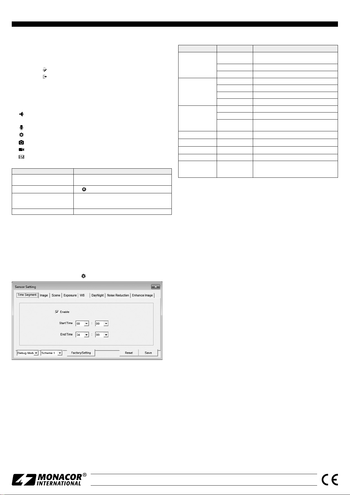
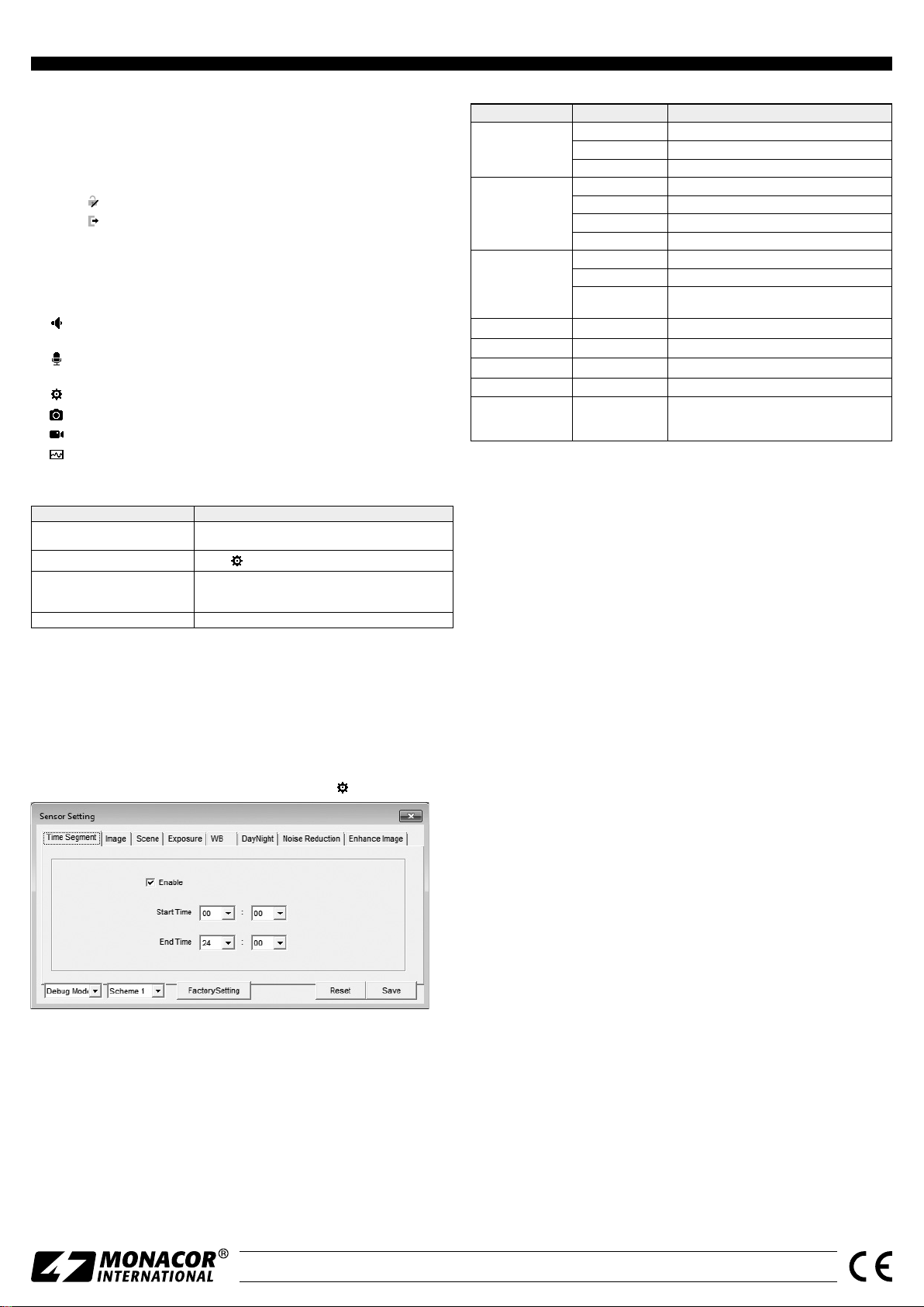
6.1 Sensor-Menü
Nach dem Klicken auf das Symbol
erscheint das folgende Fenster (Abb. 5):
In der folgenden Tabelle sind die Einstellmöglichkeiten des Sensor-Menüs aufgeführt.
Ansicht Einstellung Funktion
Enable
Time Segment
Image
Scene
Exposure Shutter, Gain Belichtungseinstellungen
WB Mode, Red, Blue Weißabgleich
Day Night Mode, IR LED Tag-Nacht-Umschaltung, Infrarot-LED-Beleuchtung
Noise Reduction 2D NR, 3D NR Rauschunterdrückung
Enhance Image
Start Time Startzeitpunkt
End Time Endzeitpunkt
Brightness Helligkeit
Saturation Farbsättigung
Sharpness Bildschärfe
Contrast Kontrast
Scene Einsatzumgebung
Aisle Korridormodus
Mirror
WDR, HLC, BLC,
Anti-Shake,
Defog
eingestellter Zeitraum für diese Einstellungen
(Scheme) aktiv
Bildspiegelung: aus, horizontal, vertikal, horizontal
und vertikal
Bildoptimierung
7 Technische Daten
Bildabtaster: . . . . . . . . . . . .CMOS, 8,5 mm (1⁄3 ”)
Objektiv:
Blickwinkel: . . . . . . . . . . . . .90°
Mindestbeleuchtung:
Auflösung: . . . . . . . . . . . . . max. 30 Bilder / s bei 2592 × 1520 Bildpunkten
Elektronischer Verschluss: . .1⁄5 – ½0 000 s
Protokolle: . . . . . . . . . . . . .IPv4, IPv6, HTTPS, RTSP, DDNS, SMTP, SSL,
Kompressionsverfahren: . . . MPEG-4 H.264/ H.265, MJPEG
Videostreaming: . . . . . . . . .Mainstream 500 – 12 000 kbit /s
Netzwerk: . . . . . . . . . . . . . .Ethernet 10 / 100 Mbit / s
Einsatztemperatur: . . . . . . . −30 °C bis +60 °C
Schutzart: . . . . . . . . . . . . . .IP 67
Stromversorgung: . . . . . . . .⎓12 V/ 600 mA oder PoE IEEE 802.3af
Abmessungen: . . . . . . . . . . ⌀ 119 mm × 89 mm
Gewicht: . . . . . . . . . . . . . . .375 g
. . . . . . . . . . . . . . .2,8 mm / 1 : 1,2
. . . . .0,01 lx (Farbe)
ONVIF2.6 u. a.
Substream 100 – 6000 kbit /s
Sensor-Menü
➄
Im Listenfeld unten links kann der Modus gewählt werden. Zum Ändern der
Einstellungen den „Debug Mode“ wählen. Die im Sensor-Menü vorgenommenen
Einstellungen lassen sich mit „Save“ als Scheme 1 – 4 speichern und wieder abrufen (Auswahl über zweites Listenfeld). Für die gespeicherten Einstellungen kann
jeweils ein Gültigkeitszeitraum festgelegt werden (Ansicht „Time Segment“).
Dadurch können z. B. nachts andere Einstellungen wirksam sein als tagsüber.
Mit „Reset“ lassen sich vorgenommene Änderungen wieder auf die gespeicherten Werte zurücksetzen. Mit „Factory Setting“ werden die Werkseinstellungen wiederhergestellt.
MONACOR INTERNATIONAL GmbH & Co. KG • Zum Falsch 36 • 28307 Bremen • Germany
Copyright
©
by MONACOR INTERNATIONAL. All rights reserved.
Änderungen vorbehalten.
A-1970.99.01.05.2019
Page 4
INC-4036 DF
Order No. 18.0126
ELECTRONICS FOR SPECIALISTS ELECTRONICS FOR SPECIALISTS ELECTRONICS FOR SPECIALISTS ELECTRONICS FOR SPECIALISTS ELECTRONICS FOR SPECIALISTS ELECTRONICS
Outdoor Network Camera
These instructions are intended for installers of
video surveillance systems. Please read the in-
English
structions carefully prior to installation and keep
them for later reference. The figures mentioned
in the descriptions below can be found on an
additional sheet.
1 Applications
The camera INC-4036DF is specially designed for
video surveillance systems based on computer networks. Its housing is weatherproof; therefore, the
camera is also suited for outdoor applications. It is
equipped with a 4 megapixel image sensor and a
2.8 mm lens. The camera features include mirror
image, masking of image areas and image analysis
functions (e. g. motion detection). In the dark, the
integrated IR LEDs will illuminate a surveillance zone
of up to 20 m and the camera will switch to B / W
mode. The camera is provided with an integrated
web server with 3-way video streaming. For correct
configuration, knowledge of network technology is
indispensable.
The camera can be operated in combination with
a network video recorder (e. g. NWR-…*) or operated independently via a web browser. It is equipped
with an integrated microphone, an audio input and
an audio output so that mutual communication via a
computer will be possible.
* Hint: If this camera model does not appear in the list of
the recorder used, select the ONVIF protocol.
2 Important Notes
The camera corresponds to all relevant directives of
the EU and is therefore marked with .
CAUTION When it gets dark, the infrared LEDs will
switch on. When setting up the camera, never look
directly into the lit infrared LEDs at close range. The
infrared light may cause eye irritation. However, the
infrared radiation is far below the emission limit
and rated risk-free according to EN 62471.
Protect the camera against extreme temperatures
•
(admissible ambient temperature range: −30 °C to
+60 °C).
Never use aggressive detergents or chemicals
•
when cleaning the camera.
No guarantee claims for the camera and no liabil-
•
ity for any resulting personal damage or material
damage will be accepted if the camera is used for
other purposes than originally intended, if it is not
correctly connected or operated, or if it is not repaired in an expert way. Likewise, no liability will
be accepted for any data loss due to operating errors or a defect or for any consequential damage
caused by this data loss.
If the camera is to be put out of operation
definitively, take it to a local recycling plant
for a disposal which is not harmful to the
environment.
3 Installation
1) A test operation is recommended in order to find
the best mounting location. For this purpose, operate the camera temporarily (
2) At the mounting location (e. g. wall or ceiling),
drill three holes for fixing the camera (drilling jig
is provided) and, if necessary, drill a hole for the
connection cable.
To guide the cable through the side of the
camera support instead of guiding it through the
mounting surface, use the key provided to release
the screw (6). Remove the clamping ring (2) and
cut out the desired cable inlet (7). When reassembling the camera support, hook the clamping ring
(2) into the mounting base (1) opposite the screw
(6) before fastening the screw.
3) Screw the screws into the drill holes (use the dowels provided, if required) so that they will protrude
approx. 5 mm from the mounting surface. Place
the camera on the screws (holes in the camera
base placed on the screw heads) and turn the
camera clockwise to secure it.
If the base does not have a tight fit on the
screws, screw the screws further into the mounting surface.
4) To align the camera, release the screw (6) on the
clamping ring (2) until the camera (4) and its holder (3) will easily turn in the ring. Then fasten the
screw.
Caution: Do not aim the camera directly at the sun
or other bright light sources; this may reduce the life
of the image sensor.
next chapters).
☞
4 Connecting the Camera
The connections (9 – 12) and the cable splitter (8)
are not weatherproof; protect them accordingly.
1) Connect the camera via the RJ45 connector (9) to
an individual computer, a local computer network
or, e. g. via a router, to larger computer networks
(Internet).
2) For audio transmission via the network, an audio
source with line level (e. g. microphone with preamplifier) can be connected to the RCA connector
“Audio Input” (12) as an alternative* to the integrated microphone (5).
* to be selected in the camera settings “Device Micro-
phone” (☞chapter 6)
3) For audio reproduction, connect a headphone
amplifier or a sound system to the RCA connector
“Audio Output” (11).
4) Connect a regulated 12 V power supply unit with
a permanent rating of 600 mA (e. g. PSS-1210DC
or PS-120WP) via a DC power connector ⌀5.5 /
2.1 mm (outside / inside) to the connector (10).
Always observe the correct polarity: centre contact = +.
Alternatively, use the network cable (Power
over Ethernet IEEE 802.3af) to supply the camera
with power.
Note: Starting the camera may take a few minutes.
5 Connecting the Camera to a Network
To be able to directly address the camera for configuration via a computer, its IP address is factory-set to
192.168.0.120.
If you do not know the current address of the cam-
era, start the program “IPSearch.exe” (available
on the Monacor homepage: www.monacor.com
Support Downloads) to find the camera in the
network.
1) To start the search, click the button “Start” of
the tab “Multicast Search”. The list on the left
will show the cameras found in the network
(☞fig.2).
2) To stop the search, click the button “Stop”.
3) Select the camera from the list. The current settings of this camera can be found on the right.
4) Change the settings as required:
IP address, subnet mask and gateway address
can be defined as static values (select the option
“Device uses the following IP address”). Enter a
unique IP address for each camera. If a DHCP server is available in the network (e. g. in the router or
network video recorder), this server will be able to
automatically make settings for the camera (select
the option “Device obtains an IP address automatically”). The values assigned automatically are
highlighted in grey and cannot be changed.
5) Click the button “Modify”. After successful transmission of the modifications, the message “Modify success!” will appear.
6) Before you start a new search, click the button
“Clear All” to delete the list.
6 Calling up the Camera via a Computer
To call up the user interface of the camera, enter its IP
address in the address bar of the program Windows
Internet Explorer (IE, version 6 or higher). The IP addresses of the computer and of the camera must be
in the same subnet.
When the camera is called up, the log-in window
will appear. Select the language for the user interface. The description below refers to English. Then
enter the user name and the password (default setting for both: admin). If you use the default password, a request to change the password will appear.
It is recommended to change the password to prevent unauthorized access. Individual log-in data can
also be defined later in the camera settings. If you
change the password, make sure to remember it!
To make all functions available, installation of the
ActiveX extensions is required. These extensions will
be loaded from the camera when the camera is called
up for the first time. If necessary, reduce the security
settings of the IE accordingly to allow the installation
process. Save the installation file “NetworkSurveillance.exe” to the computer, close the IE and execute
the file.
Windows is a registered trademark of Microsoft Corporation in the
USA and other countries.
Page 5
INC-4036 DF Order No. 18.0126
ELECTRONICS FOR SPECIALISTS ELECTRONICS FOR SPECIALISTS ELECTRONICS FOR SPECIALISTS ELECTRONICS FOR SPECIALISTS ELECTRONICS FOR SPECIALISTS ELECTRONICS FOR SPECIALISTS ELECTRONICS
When a connection to the camera has been established, the view with the current camera image (fig. 3) will be displayed. The following options are available:
View “Live Video” with display of camera image
a
View “Playback“ (without function for this camera model)
b
View “Configuration” to change the camera settings
c
Button to change the password
d
Button to log out
e
Camera image with information on the stream currently transmitted
f
Toolbar with the following functions:
g
/ : Stop/Start of image transmission
“Stream”: Selection of a stream
: Activation / Deactivation of audio transmission from the camera [micro-
phone (5) / Audio Input (12)]
: Activation / Deactivation of audio transmission to the camera [Audio Out-
put (11)]
: Specific camera settings (e. g. brightness control, mirror image)
: Snapshot function to save a snapshot as an image file
: Starting /S topping a video recording on the PC
: Activation / Deactivation of image analysis functions (“Intelligent Analysis”)
When the camera image is clicked with the right mouse button, the following
menu will appear:
Menu item Function
Full Screen (Exit Full Screen)
Sensor
Zoom In / Out
Restore Panorama display of the entire image (after zooming in)
full-screen image (exit)
alternatively: double-click the image
like
zooming in / zooming out
alternatively: use the scroll wheel to zoom in/out or drag the
mouse to select the desired image section
To change the settings for the camera, select the tab c and go to the view
“Configuration” (
fig. 4). On the left (h), select the desired category for the
☞
settings. To show additional subcategories, click ⊞. To set, for example, the current time for the camera, go to “Device Date and Time”.
To save a setting that has been changed, click the green check mark ✔ or the
button “Apply”. To load the current settings from the camera, click the button
“Refresh”.
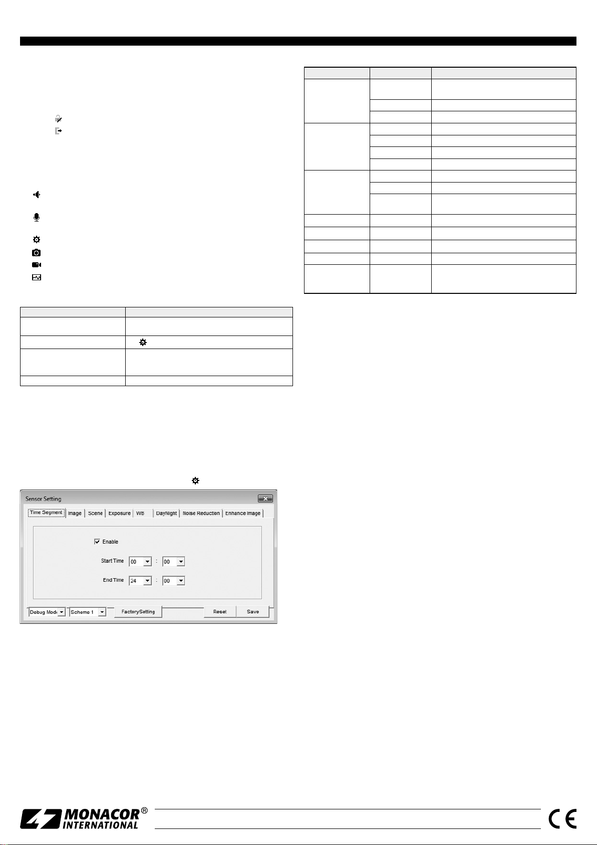
6.1 Sensor menu
To activate the sensor menu (fig. 5), click the icon
.
The setup options of the sensor menu can be found in the table below.
View Setting Function
Enable
Time Segment
Image
Scene
Exposure Shutter, Gain exposure settings
WB Mode, Red, Blue white balance
Day Night Mode, IR LED day/night switching, infrared LED illumination
Noise Reduction 2D NR, 3D NR noise reduction
Enhance Image
Start Time start of validity period
End Time end of validity period
Brightness brightness
Saturation saturation
Sharpness sharpness
Contrast contrast
Scene place of application
Aisle aisle mode
Mirror
WDR, HLC, BLC,
Anti-Shake,
Defog
activation of the validity period defined for these
settings (Scheme)
mirror image: off, horizontal, vertical, horizontal and
vertical
image enhancement
7 Specifications
Image sensor: . . . . . . . . . . .CMOS, 8.5 mm (1⁄3 ”)
. . . . . . . . . . . . . . . . . .2.8 mm / 1 : 1.2
Lens:
Viewing angle: . . . . . . . . . . 90°
Minimum illumination:
Resolution: . . . . . . . . . . . . .30 frames max. per second with
Electronic shutter:
Protocols: . . . . . . . . . . . . . .IPv4, IPv6, HTTPS, RTSP, DDNS, SMTP, SSL,
Compression:
. . . . . . . . . . .MPEG-4 H.264 / H.265, MJPEG
Video streaming: . . . . . . . . . Mainstream 500 – 12 000 kbit /s
Network: . . . . . . . . . . . . . .Ethernet 10 / 100 Mbit / s
Ambient temperature: . . . .−30 °C to +60 °C
IP rating: . . . . . . . . . . . . . . .IP 67
Power supply: . . . . . . . . . . .⎓12 V/ 600 mA or PoE IEEE 802.3af
Dimensions: . . . . . . . . . . . .⌀ 119 mm × 89 mm
Weight: . . . . . . . . . . . . . . .375 g
. . . .0.01 lx (colour)
2592 × 1520 pixels
. . . . . . . .1⁄5 – ½0 000 s
ONVIF 2.6 etc.
Substream 100 – 6000 kbit / s
Sensor menu
➄
Select the mode in the list field at the bottom on the left. To change the settings,
select “Debug Mode”. The settings made in the sensor menu can be saved with
“Save” (Schemes 1 – 4) and retrieved (selection via second list field). It is possible
to define an individual validity period for each of the settings saved (view “Time
Segment”). This will allow you, for example, to make different settings for day
and night.
To reset the settings to the values saved, click “Reset”. To reset the settings to
the factory settings, click “Factory Setting”.
MONACOR INTERNATIONAL GmbH & Co. KG • Zum Falsch 36 • 28307 Bremen • Germany
Copyright
©
by MONACOR INTERNATIONAL. All rights reserved.
Subject to technical modification.
A-1970.99.01.05.2019
Page 6

INC-4036 DF
Référence numérique 18.0126
ELECTRONICS FOR SPECIALISTS ELECTRONICS FOR SPECIALISTS ELECTRONICS FOR SPECIALISTS ELECTRONICS FOR SPECIALISTS ELECTRONICS FOR SPECIALISTS ELECTRONICS
Caméra réseau pour l’extérieur
Cette notice s’adresse aux installateurs de systèmes de vidéosurveillance. Veuillez lire la présente notice avec attention avant l’installation
Français
et conservez-la pour pouvoir vous y reporter
ultérieurement. Vous trouverez sur un feuillet
distinct les schémas des descriptions suivantes.
1 Possibilités d’utilisation
La caméra INC-4036DF est spécialement conçue pour
une utilisation dans des installations de surveillance
vidéo basée sur des réseaux informatiques. Grâce à
son boîtier étanche, elle est également adaptée à
une utilisation en extérieur. Elle est dotée d’un capteur d’image 4 mégapixels et d’un objectif 2,8 mm
et propose entre autres, une visualisation en image
miroir, un masquage de zones d’images et des fonctions d’analyse d’image (par exemple une détection
de mouvements). Dans la pénombre, les LEDs infrarouges intégrées éclairent la zone de surveillance
jusqu’à 20 m et la caméra commute en mode noir et
blanc. La caméra dispose d’un serveur web intégré
avec streaming vidéo × 3. Pour une installation correcte, des connaissances en technologie réseau sont
indispensables.
La caméra peut être utilisée en combinaison avec
un enregistreur vidéo réseau (par exemple NWR-…*)
ou seule avec un navigateur internet. Elle dispose
d’un microphone intégré, d’une entrée audio et
d’une sortie audio ; ainsi, une communication mutuelle via un ordinateur est possible
* Conseil : Si le modèle de caméra n’existe pas dans la liste
de l’enregistreur utilisé, sélectionnez le protocole ONVIF.
2 Conseils importants
La caméra répond à toutes les directives nécessaires
de l’Union européenne et porte donc le symbole .
ATTENTION Les LEDs infrarouges s’allument dans
la pénombre. Ne regardez jamais directement les
LEDs allumées de proximité. La lumière infrarouge
peut engendrer des irritations des yeux. Le rayonnement infrarouge est cependant bien en dessous
du seuil limite d’émission et classé sans risque selon
la norme EN 62471.
Protégez la caméra des températures extrêmes
•
(plage de température de fonctionnement autorisée : −30 °C à +60 °C).
Pour le nettoyage, n’utilisez pas de produits
•
chimiques ou de détergents agressifs.
Nous déclinons toute responsabilité en cas de
•
dommages corporels ou matériels résultants si la
caméra est utilisée dans un but autre que celui
pour lequel elle a été conçue, si elle n’est pas correctement branchée ou utilisée ou si elle n’est pas
réparée par une personne habilitée ; en outre, la
garantie deviendrait caduque. De même, notre
responsabilité ne saurait être engagée en cas de
pertes de données et leurs conséquences, causées
par une mauvaise utilisation ou un défaut.
Lorsque la caméra est définitivement retirée du service, vous devez la déposer dans
une usine de recyclage de proximité pour
contribuer à son élimination non polluante.
CARTONS ET EMBALLAGE
PAPIER À TRIER
3 Montage
1) Un test de fonctionnement doit être effectué afin
de définir le lieu optimal de montage. Pour ce
faire, mettez temporairement la caméra en fonction (☞chapitres suivants).
2) Sur le lieu de montage (par exemple mur ou plafond), percez trois trous pour fixer la caméra en
vous aidant du gabarit livré et percez, si besoin,
un trou pour le câble de branchement.
Si le câble ne doit pas sortir via la surface de
montage mais du support de la caméra par le
côté, desserrez la vis (6) avec la clé livrée. Retirez
la bague de serrage (2) et découpez le passage de
câble souhaité (7). Pour remonter le support de la
caméra, fixez tout d’abord la bague (2) face à la vis
(6) dans le socle de montage (1) puis revissez la vis.
3) Vissez les vis (si besoin avec les chevilles livrées)
dans les trous de telle sorte qu’elles dépassent de
5 mm environ de la surface de montage. Placez
la caméra avec les trous dans le socle sur les têtes
des vis et verrouillez en tournant dans le sens des
aiguilles d’une montre.
Si le socle ne tient pas assez sur les vis, vissez
un tout petit peu plus les vis.
4) Pour orienter la caméra, desserrez la vis (6) de la
bague de serrage (2) de telle sorte que la caméra
(4) et sa structure de maintien (3) puissent facilement tourner dans la structure. Revissez ensuite
la vis.
Attention : Evitez d’orienter la caméra directement
vers des sources puissantes de lumière (par exemple
soleil). Cela pourrait réduire la durée de vie du capteur
d’image.
4 Branchement de la caméra
Les connexions (9 –12) et le répartiteur de câble (8)
ne sont pas étanches. Vous devez les protéger en
conséquence.
1) Reliez la caméra via la fiche RJ45 (9) à un ordinateur individuel, un réseau local d’ordinateurs ou,
par exemple, via un routeur, à des réseaux plus
importants d’ordinateurs (internet).
2) Pour la transmission audio via le réseau, on peut
brancher, à la place* du microphone intégré (5),
une source audio avec niveau ligne (par exemple
microphone avec préamplificateur) à la prise RCA
«Audio Input» (12).
* sélectionnable dans les réglages de caméra «Device
Microphone» (☞chapitre 6)
3) Pour la restitution audio, branchez un amplificateur casque ou une installation de haut-parleurs à
la prise RCA «Audio Output» (11).
4) Reliez un bloc secteur 12 V stabilisé avec une
puissance continue de 600 mA (par exemple
PSS-1210DC ou PS-120WP) à la fiche (10) via
une fiche alimentation ⌀ 5,5 / 2,1 mm (diamètre
extérieur/ diamètre intérieur). Veillez à respecter la
polarité : contact médian = +.
A la place, la caméra peut être alimenté via le
câble réseau (Power over Ethernet IEEE 802.3af).
Remarque : Le processus de démarrage de la caméra
peut durer quelques minutes.
5 Intégrer la caméra dans un réseau
Pour que la caméra puisse être directement adressée
via un ordinateur pour la configuration, son adresse
IP est préréglée, en usine, sur 192.168.0.120.
Si l’adresse actuelle de la caméra n’est pas connue,
démarrez le programme «IPSearch.exe» pour trouver
la caméra dans le réseau (disponible sur le site de Monacor : www.monacor.com Support Downloads)
1) Pour démarrer la recherche, cliquez sur le bouton
«Start» sur l‘onglet «Multicast Search». Les caméras trouvées dans le réseau sont affichées dans la
liste sur le côté gauche (☞schéma 2).
2) Pour terminer la recherche, cliquez sur le bouton
«Stop».
3) Sélectionnez la caméra dans la liste. Les réglages
actuels de la caméra sont affichés maintenant sur
le côté droit.
4) Si besoin, modifiez les réglages :
L’adresse IP, le masque sous-réseau et l’adresse
Gateway peuvent être déterminées de manière
statique (sélectionnez l’option «Device uses the
following IP address»). Il faut une adresse IP
unique pour chaque caméra. Si dans le réseau,
il existe un serveur DHCP (par exemple dans le
routeur ou l’enregistreur vidéo réseau), il peut
effectuer automatiquement les réglages pour la
caméra (sélectionnez l’option «Device obtains an
IP address automatically») ; les valeurs attribuées
automatiquement apparaissent sur un fond gris et
ne peuvent pas être modifiées.
5) Cliquez sur le bouton «Modify». Lorsque la transmission des modifications est réussie, le message
«Modify success!» s’affiche.
6) La liste peut être effacée avant une nouvelle
recherche via le bouton «Clear All».
6 Appeler une caméra via un ordinateur
L’interface utilisateur de la caméra peut être appelée
en saisissant son adresse IP dans la ligne d’adresse du
programme Windows Internet Explorer (IE, Version6
ou supérieur). Pour ce faire, il faut que les adresses
IP de l’ordinateur et de la caméra appartiennent au
même sous-réseau.
Lorsque vous appelez la caméra, la fenêtre d‘ou-
verture de session s’affiche en premier. Sélectionnez
la langue pour l’interface utilisateur : la description
suivante se réfère au réglage «English». Ensuite, saisissez le nom utilisateur et le mot de passe (préréglage pour les deux saisies : admin). Lorsque vous
vous connectez avec ces données préétablies, un
message apparait vous demandant de modifier le
mot de passe. Cela est impératif pour éviter tout
accès non autorisé. Les données d’accès peuvent
également être modifiées ultérieurement dans les
réglages de la caméra. Veillez à bien noter le mot
de passe !
Pour pouvoir utiliser toutes les fonctions, l’ins-
tallation des extensions ActiveX est indispensable.
Elles sont chargées à partir de la caméra la première
fois qu’elle est appelée. Si besoin, il faut réduire
les réglages de sécurité de IE pour que le processus soit autorisé. Mémorisez le fichier d’installation
«NetworkSurveillance.exe» sur l’ordinateur, fermez
IE et exécutez le fichier.
Windows est une marque déposée de Microsoft Corporation aux
Etats-Unis et dans les autres pays.
Page 7
INC-4036 DF Référence numérique 18.0126
ELECTRONICS FOR SPECIALISTS ELECTRONICS FOR SPECIALISTS ELECTRONICS FOR SPECIALISTS ELECTRONICS FOR SPECIALISTS ELECTRONICS FOR SPECIALISTS ELECTRONICS FOR SPECIALISTS ELECTRONICS
Lorsque la connexion à la caméra est établie, la visualisation indiquée sur le schéma 3 avec l’image actuelle de la caméra s’affiche, avec les possibilités suivantes
d’utilisation :
Visualisation «Live Video» avec affichage de l’image de la caméra
a
Visualisation «Playback» (sans fonction sur ce modèle de caméra)
b
Visualisation «Configuration» pour modifier les réglages de caméra
c
Bouton pour modifier le mot de passe
d
Bouton pour se déconnecter
e
Image de la caméra avec des informations sur le stream actuellement transmis
f
Barre de fonctions avec les fonctions suivantes
g
/ : Quitter/ Démarrer la transmission d’images
«Stream»: sélection d’un stream
: Activation / Désactivation de la transmission audio depuis la caméra
[microphone (5) /Audio Input (12)]
: Activation / Désactivation de la transmission audio vers la caméra
[Audio Output (11)]
: Réglages spécifiques de caméra (p. ex. réglage luminosité, mode miroir)
: Fonction capture pour mémoriser un instantané comme image
: Marche /Arrêt d’un enregistrement vidéo sur le PC
: Activation / Désactivation des fonctions d’analyse d’image
(«Intelligent Analysis»)
Par un clic droit de la souris sur l’image de la caméra, le menu suivant s’affiche :
Point menu Fonction
Full Screen (Exit Full Screen)
Sensor
Zoom In / Out
Restore Panorama Afficher l’image entière (après Zoom In)
Visualisation image plein écran (quitter)
Alternative : double clic sur l’image
comme
Zoom In / Out Zoom avant / arrière
Alternative : avec la molette de la souris, zoomez ou tirez un
cadre sur la section d’image voulue
Pour modifier les réglages pour la caméra, commutez sur la fenêtre «Configuration» (☞schéma 4) via l‘onglet c. Sélectionnez la rubrique voulue pour
les réglages dans le bord gauche (h). En cliquant sur ⊞, vous pouvez afficher
des sous-rubriques supplémentaires. Ainsi, on peut régler, par exemple l’heure
actuelle pour la caméra via «Device Date and Time».
Une fois le réglage modifié, cliquez sur la coche verte ✔ pour cocher ou cliquez
sur le bouton «Apply» pour mémoriser la modification. Pour charger les réglages
actuels depuis la caméra, cliquez sur le bouton «Refresh».
6.1 Menu capteur – Sensor –
La fenêtre (schéma 5) s’affiche en cliquant sur le symbole
:
Vous trouverez dans le tableau suivant les possibilités de réglage du menu Sensor.
Visualisation Réglage Fonction
Enable Durée réglée pour ces réglages (Scheme) activée
Time Segment
Image
Scene
Exposure Shutter, Gain Réglages de l’exposition
WB Mode, Red, Blue Compensation du blanc
Day Night Mode, IR LED
Noise Reduction 2D NR, 3D NR Elimination du bruit
Enhance Image
Start Time Heure de démarrage
End Time Heure de fin
Brightness Luminosité
Saturation Saturation des couleurs
Sharpness Netteté image
Contrast Contraste
Scene Environnement utilisation
Aisle Mode corridor
Mirror
WDR, HLC, BLC,
Anti-Shake,
Defog
Mode miroir : désactivé, horizontal, vertical,
horizontal et vertical
Commutation jour/ nuit, éclairage LED infrarouge
Optimisation de l’image
7 Caractéristiques techniques
Capteur image : . . . . . . . . . CMOS, 8,5 mm (1⁄3 ”)
Objectif :
Angle : . . . . . . . . . . . . . . . .90°
Luminosité minimale :
Résolution : . . . . . . . . . . . . . 30 images /s max. pour 2592 × 1520 points
Obturation électronique : . . 1⁄5 – ½0 000 s
Protocoles : . . . . . . . . . . . . .IPv4, IPv6, HTTPS, RTSP, DDNS, SMTP, SSL,
Processus compression :
Streaming vidéo : . . . . . . . . Mainstream 500 – 12 000 kbit /s
Réseau : . . . . . . . . . . . . . . . Ethernet 10 / 100 Mbit / s
Température fonc. : . . . . . . . −30 °C à +60 °C
Type protection : . . . . . . . . . IP 67
Alimentation : . . . . . . . . . . .⎓12 V/ 600 mA ou PoE IEEE 802.3af
Dimensions : . . . . . . . . . . . .⌀ 119 mm × 89 mm
Poids : . . . . . . . . . . . . . . . . . 375 g
. . . . . . . . . . . . . . .2,8 mm / 1 : 1,2
. . . . .0,01 lx (couleur)
ONVIF 2.6, et autres
. . .MPEG-4 H.264/ H.265, MJPEG
Substream 100 – 6000 kbit /s
Menu Sensor
➄
Vous pouvez sélectionner le mode dans le champ en bas à gauche. Pour modifier
les réglages, sélectionnez «Debug Mode». Les réglages effectués dans le menu
Sensor peuvent être mémorisés avec «Save» comme Scheme 1 – 4 puis rappelés
(sélection via un second champ). Pour les réglages mémorisés, on peut définir une
durée de validité (visualisation «Time Segment»). Cela signifie, par exemple, que
des réglages différents peuvent être efficaces la nuit et le jour.
Avec «Reset», on peut réinitialiser toutes les modifications réalisées sur les
valeurs mémorisées. Avec «Factory Setting», les réglages usine sont rétablis.
MONACOR INTERNATIONAL GmbH & Co. KG • Zum Falsch 36 • 28307 Bremen • Germany
Copyright
©
by MONACOR INTERNATIONAL. All rights reserved.
Tout droit de modification réservé.
A-1970.99.01.05.2019
 Loading...