

Page 1
ELECTRONICS FOR SPECIALISTS ELECTRONICS FOR SPECIALISTS ELECTRONICS FOR SPECIALISTS ELECTRONICS FOR SPECIALISTS
BEDIENUNGSANLEITUNG
INSTRUCTION MANUAL
Netzwerkkamera
mit Kfz-Kennzeichen-Erkennung
Network Camera
with Number Plate Recognition
INC-2722 BCP
Bestellnummer • Order Number 18.0121
Page 2
2
12V
LAN
Audio Input
Audio Output
Alarm
IN0
COM0
OUT1
COM1
6
2
4
1
7
8
9
10
11
5
3
54
13
12
14
1715 16
“TOP”
“TOP”
13
16
①
②
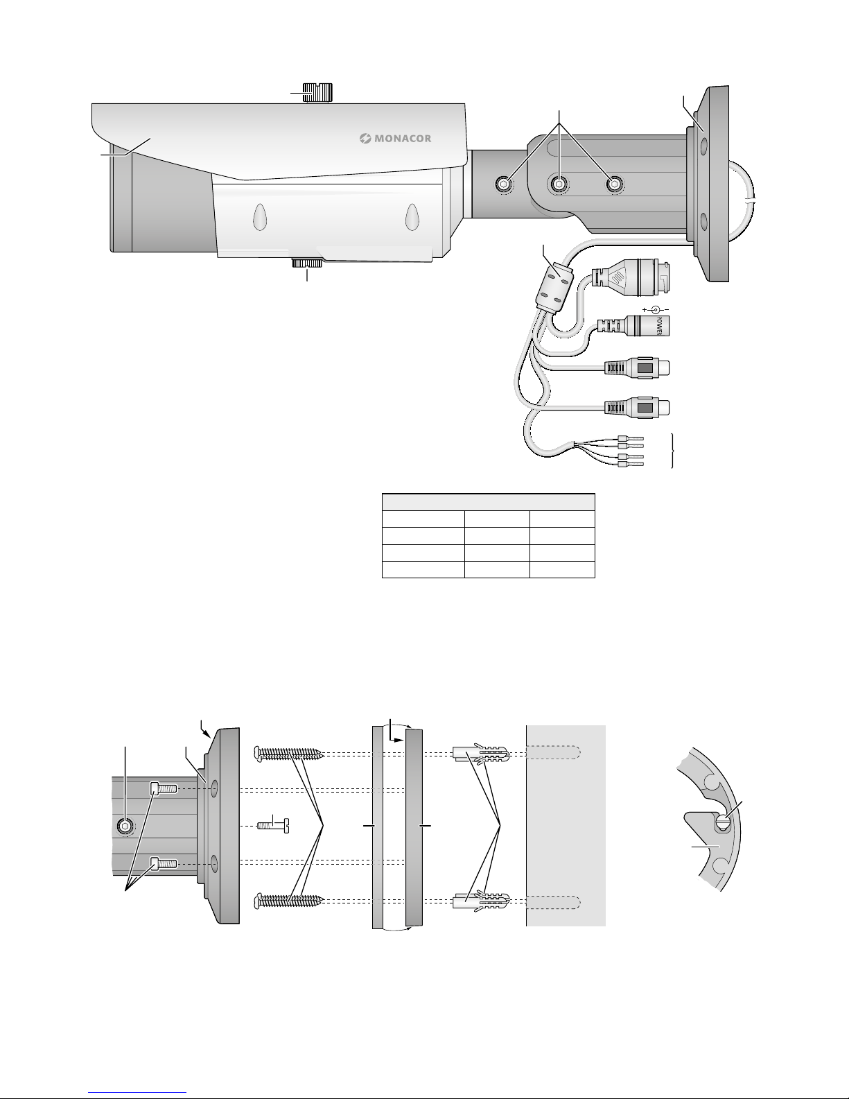
Alarm (11)
Alarm COM 0 orange orange
Alarm IN 0 gelb yellow
Alarm OUT 1 grau grey
Alarm COM 1 violett purple
③
Page 3

ELECTRONICS FOR SPECIALISTS ELECTRONICS FOR SPECIALISTS ELECTRONICS FOR SPECIALISTS ELECTRONICS FOR SPECIALISTS
3
Deutsch
1 Verwendungsmöglichkeiten. . . . . . . . . . . 4
1.1 Kfz-Kennzeichen-Erkennung . . . . . . . . . . . . 4
2 Wichtige Hinweise . . . . . . . . . . . . . . . . 4
3 Montage . . . . . . . . . . . . . . . . . . . . . 4
4 Kamera anschließen . . . . . . . . . . . . . . . 5
5 Kamera in ein Netzwerk einbinden . . . . . . . 6
6 Kamera über einen Computer aufrufen. . . . . 6
6.1 Sensor-Menü . . . . . . . . . . . . . . . . . . . . 7
6.2 Zoom-Objektiv einstellen . . . . . . . . . . . . . . 8
6.3 Configuration-Menü . . . . . . . . . . . . . . . . 8
6.3.1 List Configure. . . . . . . . . . . . . . . . . . 8
6.3.2 Parameter Configure . . . . . . . . . . . . . . 9
6.3.3 Linkage Configure . . . . . . . . . . . . . . . 9
6.3.4 LPR Search . . . . . . . . . . . . . . . . . . .10
7 Zurücksetzen der Kamera . . . . . . . . . . . .10
8 Technische Daten . . . . . . . . . . . . . . . . .10
English
1 Applications. . . . . . . . . . . . . . . . . . . .12
1.1 Number plate recognition . . . . . . . . . . . . .12
2 Important Notes . . . . . . . . . . . . . . . . .12
3 Installation . . . . . . . . . . . . . . . . . . . .12
4 Connecting the Camera . . . . . . . . . . . . .13
5 Connecting the Camera to a Network . . . . .14
6 Calling up the Camera via a Computer . . . . .14
6.1 Sensor menu . . . . . . . . . . . . . . . . . . . .15
6.2 Adjusting the zoom lens . . . . . . . . . . . . . .16
6.3 Configuration menu . . . . . . . . . . . . . . . .16
6.3.1 List Configure. . . . . . . . . . . . . . . . . .16
6.3.2 Parameter Configure . . . . . . . . . . . . . .17
6.3.3 Linkage Configure . . . . . . . . . . . . . . .17
6.3.4 LPR Search . . . . . . . . . . . . . . . . . . .18
7 Resetting the Camera . . . . . . . . . . . . . .18
8 Specifications . . . . . . . . . . . . . . . . . . .18
Page 4
4
Deutsch
Netzwerk-Außenkamera mit
Kfz-Kennzeichen-Erkennung
Diese Anleitung richtet sich an Installateure von Video überwachungsanlagen. Bitte
lesen Sie die Anleitung vor der Installation
gründlich durch und heben Sie sie für ein
späteres Nachlesen auf.
1 Verwendungsmöglichkeiten
Die Kamera INC-2722BCP ist speziell für
den Einsatz in Video-Überwachungsanlagen auf der Basis von Computer-Netzwerken konzipiert. Durch ihr wetterfestes
Gehäuse (Schutzart IP 67) ist sie auch für
die Außeninstallation geeignet. Sie ist mit
einem Motorzoom-Objektiv ausgestattet
und bietet u. a. Bildspiegelung, Maskierung
von Bildbereichen, Bewegungs erkennung
und als Besonderheit die Erkennung von
Kfz-Kennzeichen. Bei Dunkelheit leuchten
die eingebauten Infrarot-LEDs den Überwa
chungsbereich bis 70 m aus und die Kamera
schaltet auf Schwarzweißbetrieb um. Die
Kamera verfügt über einen eingebauten
Webserver mit 2-fach-Video streaming. Für
die korrekte Einrichtung sind unbedingt
Netzwerktechnik-Kennt nisse er forderlich.
Die Kamera kann in Verbindung mit
einem Netzwerk-Videorekorder (z. B.
NWR-…*) genutzt werden oder eigenständig über einen Webbrowser. Sie verfügt über einen Audio eingang und einen
Audio ausgang, sodass eine gegenseitige
Kom munikation über einen Computer
möglich ist. Zusätzlich verfügt die Kamera über einen Alarmeingang, über den
z. B. eine Aufzeichnung oder eine E-MailBenachrichtigung gestartet werden kann.
Ein Steckplatz für eine Speicherkarte
erlaubt die Videoaufzeichnung in der
Kamera, nach Zeitplan oder durch einen
aufgetretenen Alarm ausgelöst.
* Tipp: Ist das Kameramodell in der Liste des ver-
wendeten Rekorders nicht vorhanden, das
ONVIF-Protokoll wählen.
1.1 Kfz-Kennzeichen-Erkennung
Mit der INC-2722BCP lassen sich automatisch Kennzeichen von Fahrzeugen erfassen. Diese können mit Kennzeichenlisten
verglichen werden und bei Übereinstimmung können Aktionen wie das Schalten
eines Relais über den Schaltausgang, eine
E-Mail-Benachrichtigung oder das Speichern einer Momentaufnahme per FTP
ausgelöst werden. Die Listen werden in der
Kamera gespeichert, sodass keine zusätzliche Software erforderlich ist. Mit dieser
Ausstattung lässt sich z. B. die Zufahrtskontrolle für einen Parkplatz steuern.
2 Wichtige Hinweise
Die Kamera entspricht allen relevanten
Richtlinien der EU und ist deshalb mit
gekennzeichnet.
•
Schützen Sie die Kamera vor extremen
Temperaturen (zulässige Einsatztemperatur −30 °C bis +60 °C).
•
Verwenden Sie für die Reinigung des
Kameragehäuses keine aggressiven Reinigungsmittel oder Chemikalien. Zum
Säubern des Objektivs kann ein weiches
Tuch verwendet werden, das mit Isopropylalkohol oder einem Reinigungsmittel
für optische Linsen angefeuchtet ist.
•
Wird die Kamera zweckentfremdet, nicht
richtig angeschlossen, falsch bedient
oder nicht fachgerecht repariert, kann
keine Haftung für daraus resultierende
Sach- oder Personenschäden und keine
Garantie für die Kamera übernommen
werden. Ebenso kann keine Haftung für
durch Fehlbedienung oder durch einen
Defekt entstandene Datenverluste und
deren Folgeschäden übernommen werden.
Soll die Kamera endgültig aus dem
Betrieb genommen werden, übergeben Sie sie zur umweltgerechten
Entsorgung einem ört lichen Recyclingbetrieb.
3 Montage
Für die optimale Erkennung der Kennzeichen müssen bestimmte Voraussetzungen
bei der Wahl des Montageorts eingehalten
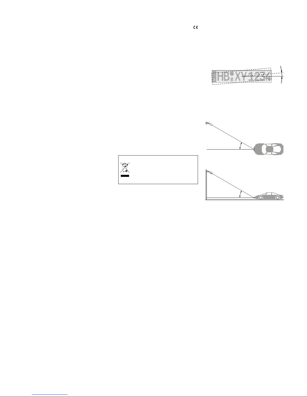
werden.
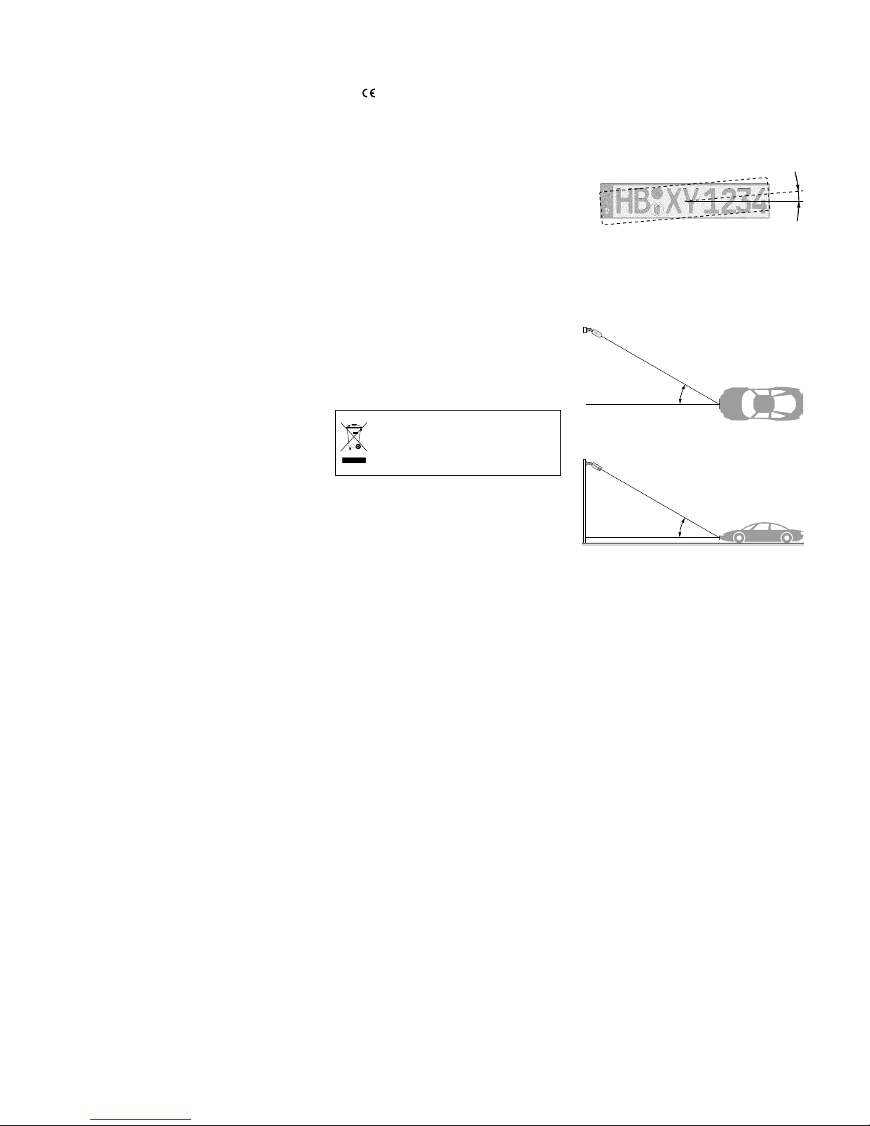
Die Kamera sollte möglichst gerade auf die
zu erkennenden Kennzeichen blicken, es ist
aber eine Verdrehung des Kenn zeichens bis
±5° zulässig.
④
≤ 5°
Der Blickwinkel der Kamera auf das zu erfassende Kennzeichen darf für die optimale
Erkennung horizontal (Abb. 5) wie vertikal
(Abb. 6) nicht mehr als 30° von der Senkrechten abweichen.
d ≤ 30°
⑤
≤ 30°d
h
⑥
Am Beispiel der Montagehöhe bedeutet
das: der Abstand (d) muss mindestens das
1,7fache der Montagehöhe (h) betragen.
Bei zu großem Abstand wird jedoch
die für die Erkennung erforderliche Mindestgröße der Kennzeichen unterschritten.
Für einzeilige Kennzeichen ist, je nach Land,
eine Mindestbreite von 130 – 150 Bildpunkten (Pixel) erforderlich, was etwa 7 – 8 % der
Bildbreite bei voller Auflösung entspricht.
Eine größere Abbildung der Kennzeichen
kann auch durch Heranzoomen mithilfe des
Objektivs erreicht werden (☞Kapitel 6.2).
Page 5

5
Deutsch
1) Um die optimale Montagestelle festzustellen, sollte ein Probebetrieb erfolgen.
Dazu die Kamera vorläufig in Betrieb
nehmen (☞folgende Kapitel).
2) An der Montagestelle (z. B. Wand oder
Decke) vier Löcher für die Befestigung
der Montageplatte und ggf. ein Loch für
das An schluss kabel bohren (das Kabel
kann alternativ durch die Aussparung
seitlich am Sockel herausgeführt werden). Eine Bohrschablone liegt bei. Bei
Bedarf die beiliegenden Dübel (17) verwenden.
3) Mit den vier langen Kreuzschlitzschrauben (14) die Montageplatte (16) an
der Montagestelle befestigen. Bei der
Wandmontage darauf achten, dass die
Beschriftung „TOP“ nach oben zeigt
(☞Abb. 2).
4)
Die Gummidichtung (15) mit etwas Dehnung über den Rand der Montageplatte
(16) stülpen.
5)
Die Schlitzschraube (13) bis zum Anschlag in das Gewinde am Kamerahaltersockel (5) drehen.
6)
Den Sockel (5) so auf die Montageplatte
(16) setzen, dass der Schraubenkopf in
die Öffnung in der Montageplatte fasst
und sich nach einer Linksdrehung des
Sockels darin verriegelt (☞ Abb. 3).
7)
Mit den vier Inbusschrauben (12) den
Sockel (5) an der Montageplatte (16)
festschrauben.
8)
Zum Ausrichten der Kamera die drei
Feststellschrauben (4) lösen, die Kamera
ausrichten und die Schrauben wieder
festdrehen.
Vorsicht: Vermeiden Sie die direkte Ausrichtung
der Kamera auf starke Lichtquellen
(z. B. Sonne). Dies könnte die Lebensdauer des Bildsensors verkürzen.
9)
Um das Objektiv vor direkter Sonneneinstrahlung zu schützen, das Sonnendach
(1) auf der Kamera positionieren und mit
der Feststellschraube (2) fixieren.
4 Kamera anschließen
Die Anschlüsse (7 – 11) und der Kabelverteiler (6) sind nicht wetterfest. Sie müssen
entsprechend geschützt werden.
1)
Die Kamera über den RJ45-Anschluss (7)
mit einem einzelnen Computer, einem
lokalen Computernetzwerk oder, z. B.
über einen Router, mit größeren Computernetzwerken (Internet) verbinden.
Auf der Kameraunterseite ist durch das
Fenster im Deckel des Fachs eine gelbe
LED (20 in Abb. 7) sichtbar. Diese blinkt
beim Bestehen einer Netzwerkverbindung.
2) Für die Tonübertragung über das Netzwerk kann an die Cinch-Kupplung
„AudioInput“ (9) eine Tonquelle mit
Line-Pegel (z. B. Mikrofon mit Vorverstärker) angeschlossen werden.
3)
Für die Tonwiedergabe an die CinchKupplung „Audio Output“ (10)
einen Kopfhörerverstärker oder eine
Lautsprecher anlage anschließen.
4) Zur Auswertung eines Alarmgebers die
Anschlüsse (11) IN 0 und COM 0 über
einen Schließkontakt oder Öffner (in
den Kameraeinstellungen wählbar) verbinden.
5)
Zum Schalten eines Geräts, z. B. über
ein Relais, dieses an den Schaltausgang
OUT 1 und COM 1 der Kamera anschließen (11). Die Schalt charakteristik
(Öffner/ Schließer) ist in den Kameraeinstellungen wählbar (☞ Kapitel 6.3.3).
Der Ausgang ist max. mit ⎓12 V/ 300 mA
belastbar.
6)
Zum Einsetzen einer Speicherkarte und/
oder zur Verwendung des analogen
Video ausgangs nach Lösen der Schraube (3) den Deckel des Fachs öffnen. Das
Fach ist in Abb. 7 gezeigt. Nach dem Einsetzen der Speicherkarte oder Nutzung
des Videoausgangs den Deckel wieder
dicht verschließen.
⑦
21
19
20
22
18
7)
Soll die Kamera eigenständig VideoAufzeichnungen durchführen, eine
Speicher karte vom Typ „SD[HC]“ (max.
64 GB) einsetzen.
Den Schreibschutz der Karte (seitlicher
Schieber) deaktivieren. Die Karte mit den
Kontakten zur Kamera vorderseite zeigend in den Schlitz (18) schieben, bis
sie einrastet. Die rote LED (19) leuchtet
bei eingesetzter Karte. Ein Adapter für
Karten vom Typ „micro SD[HC]“ liegt bei.
Vor dem Entnehmen der Karte eine
laufende Aufnahme unbedingt beenden! Die Karte dann etwas hineindrücken, sodass sie ausrastet.
8)
Als Hilfe für die Ausrichtung der Kamera
steht im Fach an der Kameraunter seite
ein Ausgang mit einem analogen Videosignal zur Verfügung, wenn die Signalausgabe in den Kamera einstellungen
„Device CVBS“ aktiviert wurde (☞Kapitel 6). Die Cinch- Buchse (22 in Abb.7)
mit dem Eingang eines Monitors verbinden.
9)
An die Kupplung (8) ein stabilisiertes
12-V-Netz gerät mit einer Dauerbelastbarkeit von 700 mA (z. B. PSS-1210DC
oder PS-120WP) über einen Hohlstecker
⌀ 5,5 / 2,1 mm (außen / innen) anschließen. Dabei die Polung beachten:
Mittelkontakt = +
Alternativ lässt sich die Kamera auch
über das Netzwerkkabel versorgen
(Power over Ethernet IEEE 802.3af).
Page 6
6
Deutsch
5 Kamera in ein Netzwerk einbinden
Damit die Kamera zum Konfigurieren über einen Computer direkt
angesprochen werden kann, ist ihre IP-Adresse vom Werk aus
auf 192.168.0.120 voreingestellt. Die aktuelle Adresse der Kamera wird im Bildsignal am analogen Hilfsausgang (22 in Abb.7)
eingeblendet, wenn die Signalausgabe und die Einblendung „IP
Show“ in den Kamera einstellungen „Device CVBS“ aktiviert
wurden (☞ Kapitel 6).
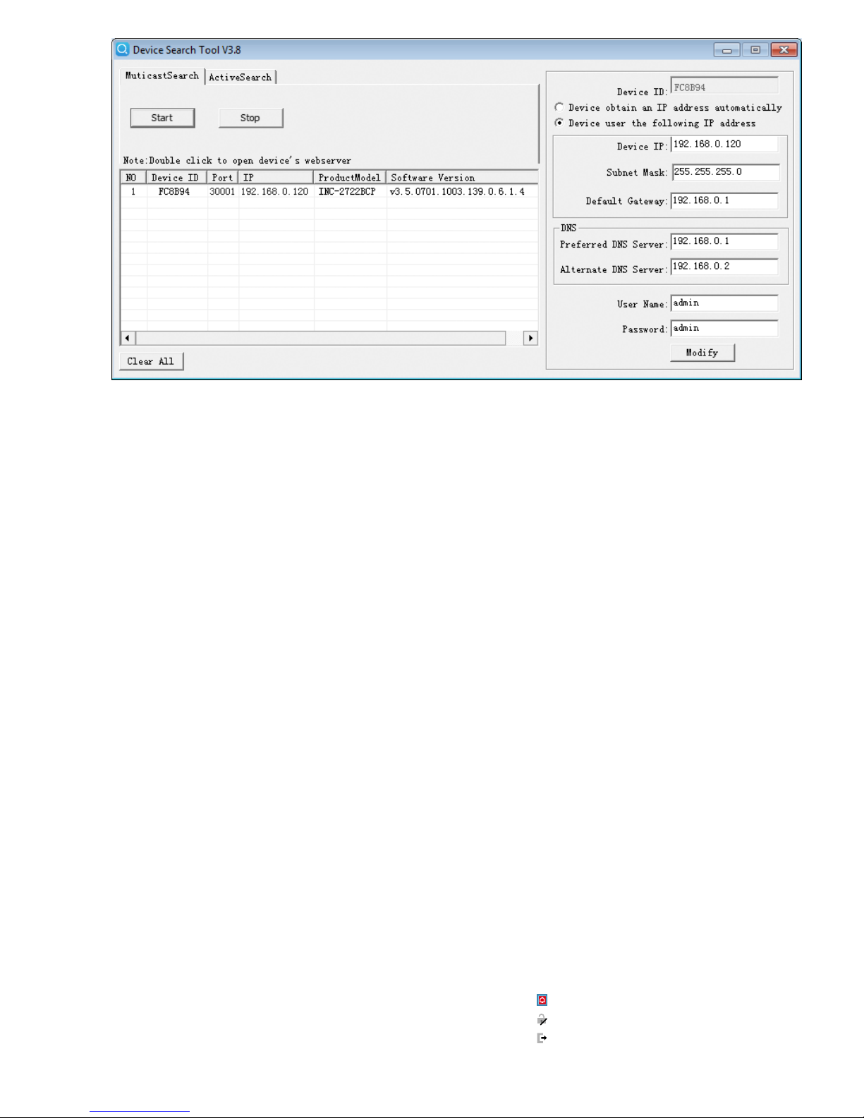
Ist die aktuelle Adresse der Kamera nicht bekannt, zum Finden
der Kamera im Netzwerk das Programm „IPSearch.exe“ starten.
Dies ist auf der beiliegenden CD enthalten oder kann von der
MONACOR-Website heruntergeladen werden.
1)
Um die Suche zu starten, auf der Registerkarte „Multicast
Search“ die Schaltfläche „Start“ anklicken. Die im Netzwerk
gefundenen Kameras werden in der Liste auf der linken Seite
angezeigt (☞Abb.8).
2) Zum Beenden der Suche auf die Schaltfläche „Stop“ klicken.
3) Die Kamera in der Liste auswählen. Auf der rechten Seite werden jetzt die aktuellen Einstellungen dieser Kamera gezeigt.
4) Die Einstellungen nach Bedarf ändern:
IP-Adresse, Teilnetzmaske und Gateway-Adresse können statisch festgelegt werden (Option „Device uses the following IP
address“ wählen). Dabei muss für jede Kamera eine eindeutige
IP-Adresse eingegeben werden. Existiert in dem Netzwerk ein
DHCP-Server (z. B. im Router oder Netzwerk-Videorekorder),
kann dieser Einstellungen für die Kamera automatisch vornehmen (Option „Device obtains an IP address automatically“
wählen); die automatisch vergebenen Werte sind dann grau
hinterlegt und können nicht geändert werden.
5) Auf die Schaltfläche „Modify“ klicken. Bei erfolgreicher Übertragung der Änderungen wird die Meldung „Modify success!“
angezeigt.
6) Vor einer erneuten Suche kann die Liste über die Schaltfläche
„Clear All“ gelöscht werden.
6 Kamera über einen Computer aufrufen
Die Bedienoberfläche der Kamera kann durch die Eingabe ihrer
IP-Adresse in der Adresszeile des Programms Windows Internet
Explorer (IE, Version 6 oder höher) aufgerufen werden. Dazu müssen die IP-Adressen des Computers und der Kamera demselben
Teilnetz angehören. Es sind max. 6 gleichzeitige Zu griffe auf die
Kamera möglich.
Windows ist ein registriertes Warenzeichen der Microsoft Corporation in den USA und anderen
Ländern.
Beim Aufruf der Kamera erscheint zunächst das Anmeldefenster. Hier die Sprache für die Benutzeroberfläche wählen; die folgende Beschreibung bezieht sich auf die Einstellung „ English“.
Anschließend den Benutzernamen und das Passwort eingeben
(Vorgabe für beide Eingaben: admin). Bei einer Anmeldung mit
diesen Vorgabedaten erscheint eine Aufforderung, das Passwort
zu ändern. Dies wird gegen einen unbefugten Zu gang unbedingt
empfohlen. Diese Zugangsdaten können aber auch später in den
Kamera einstellungen geändert werden. Ein geändertes Passwort
gut merken!
Für die Nutzbarkeit aller Funktionen ist die Installation der
ActiveX-Erweiterungen erforderlich. Diese werden beim erstmaligen Aufruf aus der Kamera geladen. Wenn nötig, müssen
dafür die Sicherheitseinstellungen des IE so gelockert werden,
dass dieser Vorgang zugelassen wird. Die Installationsdatei
„NetworkSurveillance.exe“ auf dem Computer speichern, den IE
schließen und die Datei ausführen.
Ist die Verbindung zur Kamera aufgebaut, wird die in Abb. 9
gezeigte Ansicht mit dem aktuellen Kamerabild angezeigt, mit
folgenden Bedienmöglichkeiten:
a
Ansicht „Live Video“ mit Anzeige des Kamerabilds
b
Ansicht „Playback“ zum Abspielen der Aufnahmen aus der
Kamera
c
Ansicht „Configuration“ zum Ändern der Kameraeinstellungen
d
Schaltfläche zum Anzeigen und Quittieren eines Alarms
e
Schaltfläche zum Ändern des Passworts
f
Schaltfläche zum Abmelden
g
Kamerabild mit Informationen zum aktuell übertragenen Stream
⑧
Page 7

7
Deutsch
g
h
i
f
a
j
b c
e d
h
Funktionsleiste mit folgenden Funktionen
/ : Beenden / Starten der Bildübertragung
„Stream“: Auswahl eines Streams (zur Änderung die Übertra-
gung eines laufenden Streams mit beenden)
: Tonübertragung von der Kamera ein-/ausschalten
[Audio Input (9)]
: Tonübertragung zu der Kamera ein-/ausschalten
[Audio Output (10)]
: spezifische Kameraeinstellungen
(z. B. Bildeinstellungen, Tag/Nacht, Zoom/Fokus)
: Schnappschuss-Funktion zum Speichern einer Moment-
aufnahme als Bild
i
Anzeigefeld für das zuletzt erkannte Kennzeichen:
Time = Erkennungszeitpunkt
License Plate Number = erkanntes Kennzeichen
Direction = erkannte Fahrtrichtung
Action = ausgelöste Aktion
List = Listenzugehörigkeit
Country = Land (Ländercode nach ISO 3166)
j
Tabelle der zuletzt erkannten Kennzeichen
Das Klicken mit rechter Maustaste auf das Kamerabild zeigt fol-
gendes Menü:
Menüpunkt Funktion
Full Screen (Exit Full Screen)
Vollbildansicht (beenden)
alternativ: Doppelklick auf das Bild
Sensor
wie
Zoom In / Out
Hinein-/Herauszoomen
(= Vergrößerung eines Bildausschnitts, für
optischen Zoom ☞Kapitel 6.2)
alternativ: mit Mausrad zoomen oder über
dem gewünschten Bildausschnitt
einen Rahmen aufziehen
Restore Panorama gesamtes Bild zeigen (nach Zoom In)
Zum Ändern der Einstellungen für die Kamera, über den Reiter
c
auf die Ansicht „Configuration“ umschalten (☞Abb. 11).
Am linken Rand (k) die gewünschte Rubrik für die Einstellungen
auswählen. Durch Klicken auf ⊞ lassen sich weitere Unterrubriken
anzeigen. So lässt sich z. B. unter „Device Date and Time“ die
aktuelle Zeit für die Kamera einstellen. Eine richtige Zeiteinstellung
ist Voraussetzung für die Verwaltung der Kennzeichenlisten.
Nach dem Ändern einer Einstellung zum Speichern der Änderung auf den grünen Haken ✔ oder die Schaltfläche „Apply“
klicken. Zum Laden der aktuellen Einstellungen aus der Kamera
auf die Schaltfläche „Refresh“ klicken.
Die Einstellmöglichen der INC-2722BCP entsprechen größtenteils
denen von üblichen Netzwerkkameras. Im Folgenden werden deshalb nur die speziellen Einstellungen für diese Kamera beschrieben.
6.1 Sensor-Menü
Nach dem Klicken auf das Symbol erscheint die folgende Einblendung (Abb. 10):
⑩
Sensor-Menü
Im Listenfeld unten links kann der Modus gewählt werden. Zum
Ändern der Einstellungen den „Debug Mode“ wählen. Die im
Sensor-Menü vorgenommenen Einstellungen (Ausnahme: Zoom/
Focus) lassen sich mit „Save“ als Scheme 1 – 4 speichern und wie-
⑨
Page 8

8
Deutsch
der abrufen (Auswahl über zweites Listenfeld). Für die gespeicherten Einstellungen kann jeweils ein Gültigkeitszeitraum festgelegt
werden (Ansicht „Time Segment“). Dadurch können z. B. nachts
andere Einstellungen wirksam sein als tagsüber.
Mit „Reset“ lassen sich vorgenommene Änderungen wieder
auf die gespeicherten Werte zurücksetzen. Mit „Factory Setting“
werden die Werkseinstellungen wiederhergestellt.
In der folgenden Tabelle sind die Einstellmöglichkeiten des Sensor-Menüs aufgeführt.
Ansicht Einstellung Funktion
Time Segment
Enable
eingestellter Zeitraum für diese Einstellungen
(Scheme) aktiv
Start Time Startzeitpunkt
End Time Endzeitpunkt
Image
Brightness Helligkeit
Saturation Farbsättigung
Sharpness Bildschärfe
Contrast Kontrast
Scene
Scene Einsatzumgebung
Aisle Korridormodus
Mirror
Bildspiegelung: aus, horizontal, vertikal,
horizontal und vertikal
Exposure
Shutter,
Gain, Iris
Belichtungseinstellungen
WB
Mode, Red,
Blue
Weißabgleich
Day Night
Mode,
IR LED
Tag-Nacht-Umschaltung, Infrarot-LED-Beleuchtung
Noise
Reduction
2D NR,
3D NR
Rauschunterdrückung
Enhance Image
WDR,
HLC, BLC,
Anti-Shake,
Defog
Bildoptimierung
Zoom Focus
Zoom,
Focus,
Auto focus
Zoom- und Fokuseinstellungen
6.2 Zoom-Objektiv einstellen
Die Einstellung des Objektivs kann über die Registerkarte „Zoom
Focus“ im Sensor-Menü (☞Kapitel 6.1) oder in der Ansicht
„ Privacy Masking“ im Configura tion-Menü mit folgenden Bedienmöglichkeiten vorgenommen werden:
: hineinzoomen
: herauszoomen
: Fokus näher
: Fokus ferner
/ : automatisch fokussieren
6.3 Configuration-Menü
Im Menü „Configuration“ (c) gibt es unter der Rubrik „License Plate Recognition“ (k) folgende Ansichten für die speziellen
Einstellungen dieser Kamera zur Kfz-Kennzeichen-Erkennung
(☞Abb. 12).
6.3.1 List Configure
In dieser Ansicht können folgende Einstellungen durchgeführt
werden:
Einstellung Funktion
License Plate Number Kfz-Kennzeichen
List Type Zugehörigkeit zu einer Liste: White List, Black List
Begin Time Anfang des Gültigkeitszeitraums
End Time Ende des Gültigkeitszeitraums
neues Kennzeichen zufügen
alle gewählten ☑ Einträge entfernen
☐ Select All alle Einträge auswählen
Liste als *.XLS exportieren
Liste importieren (*.XLS)
Eingabefeld zum Filtern bestimmter Kennzeichen
Advanced
List Type
zu konfigurierenden Listentyp wählen:
All = Aktion(en) für alle erkannten Kennzeichen
Black List = nur für Kennzeichen aus der „Black List“
White List = nur für Kennzeichen aus der „White List“
Not in List = nur für Kennzeichen, die in keiner Liste
stehen
FTP Upload eine Momentaufnahme wird per FTP gespeichert
Relay On der Alarmausgang wird geschaltet
SMTP eine E-Mail-Benachrichtigung wird verschickt
k
c
⑪
Page 9

9
Deutsch
Zum Erstellen oder Ergänzen einer Liste können in dieser Ansicht
neue Kennzeichen zugefügt werden. Dazu über das eine neue
Zeile einfügen und die entsprechenden Daten (Kennzeichen, Zugehörigkeit zur „White List“ oder „Black List“, Gültigkeitszeitraum)
eingeben. Die Eingaben der Zeile mit ✔ speichern oder mit ✖
wieder entfernen. Nach Ablauf des Gültigkeitszeitraums wird ein
Eintrag automatisch aus der Liste entfernt.
Die Liste der Kennzeichen lässt sich auch extern als Tabelle mit bis zu 1001 Einträgen erstellen, z. B. mit Microsoft Excel.
Um das dafür benötigte Tabellenformat zu erhalten, empfielt es
sich, zunächst eine Tabelle mit einigen Einträgen in dieser Ansicht
vorzunehmen und diese zu exportieren ( ), um sie dann extern
weiterzubearbeiten. Anschließend die Tabelle in dieser Ansicht
über wieder importieren.
Hinweis: Auch wenn der Name der exportierten Tabelle auf „BlackList.xls“ vor-
eingestellt ist: Es sind darin die Kennzeichen beider Listen enthalten.
Mit „Advanced“ unter der Tabelle gelangt man zur Konfiguration
der Aktionen, die durchgeführt werden sollen, wenn irgendein
Kennzeichen erkannt wurde („All“), ein erkanntes Kennzeichen
in der „Black List“oder „White List“ steht oder wenn es in keiner
der beiden Listen geführt wird („Not in List“).
Weitere Einstellungen für FTP, SMTP und das Schalten des
Alarmausgangs werden in den Ansichten „Network Service FTP“,
„Network Service SMTP“ und „License Plate Recognition Lin-
kage Configure“ vorgenommen.
6.3.2 Parameter Configure
In dieser Ansicht können folgende Einstellungen durchgeführt
werden:
Einstellung Funktion
Minimum Width of
License Plate (pixel)
Mindestbreite eines zu erkennenden Kennzeichens
(Anzahl der Bildpunkte)
Direction Angle of
Vehicle
Korrekturwert für den Blickwinkel auf das Kennzeichen
In der Voreinstellung findet die Kennzeichenerkennung im gesamten Bild statt. Sie lässt sich jedoch auf einen Teil des Bildes
beschränken. Dazu in dem gezeigten Kamerabild mit der Maus
einen Rahmen über dem gewünschten Bildausschnitt aufziehen.
Dieser wird als flackerndes, grünes Rechteck dargestellt. Mit der
rechten Maustaste lässt sich ein gewählter Ausschnitt wieder auf
das volle Bild vergrößern. Mit „Apply“ wird diese Einstellung in
der Kamera gespeichert.
6.3.3 Linkage Configure
In dieser Ansicht können folgende Einstellungen durchgeführt
werden:
Einstellung Funktion
Valid Signal
Close = Relaiskontakt wird bei Erkennung geschlossen
Open = Relaiskontakt wird bei Erkennung geöffnet
Time of Duration Dauer der Relaisaktion in Sekunden
FTP Upload
Screenshots
On/Off
Video Displaying
License Plate
Einblendung des zuletzt erkannten Kennzeichens im
Bild
Time of Duration
(0 s : Continuous)
Dauer der Einblendung in Sekunden, 0 = unbegrenzt
Weitere Einstellungen für die Art der Einblendung des zuletzt
erkannten Kennzeichens im Kamerabild werden in der Ansicht
„Device OSD“ als „LPR Info“ vorgenommen.
⑫
k
c
Page 10

10
Deutsch
6.3.4 LPR Search
In dieser Ansicht kann die Auflistung der erkannten Kennzeichen
nach bestimmten Kriterien gefiltert werden:
Einstellung Funktion
Time Zeitraum der Erkennung
Country
All = alle Länder
Kennzeichen eines Landes (Auswahlliste mit Abkür-
zungen nach ISO 3166)
License Plate Number Kennzeichen
Direction
Fahrtrichtung:
All = jede
Unknown = unbekannt
Undefined = unbestimmt
Forward = vorwärts
Reverse = rückwärts
List Type
All = alle Kennzeichen
Black List = nur Kennzeichen aus der „Black List“
White List = nur Kennzeichen aus der „White List“
Not in List = nur Kennzeichen, die in keiner Liste
stehen
7 Zurücksetzen der Kamera
Die Kamera kann auf ihre Werkseinstellungen zurückgesetzt werden. Dabei gehen alle vom Anwender durchgeführten Änderungen
der Kameraeinstellungen verloren. Sollen die angelegten Kennzeichenlisten erhalten werden, diese vor dem Zurücksetzen als
Datei exportieren und nach dem Zurücksetzen wieder importieren
(☞Kapitel 6.3.1).
1) Die Schraube (3) des Deckels lösen und das Fach öffnen.
2)
Den Reset-Taster (21) länger als 5 Sekunden drücken (☞ Abb.7
in Kapitel 4). Der Rücksetzprozess startet nach dem Loslassen
der Taste verzögert und kann einige Minuten dauern.
3) Den Deckel wieder dicht verschließen.
Die Kamera ist jetzt wieder auf die statische IP-Adresse
192.168.0.120 eingestellt, der Benutzername und das Kennwort
für die Anmeldung lauten: admin
8 Technische Daten
Bildabtaster: . . . . . . . . . . CMOS, 8,76 mm (⁄”)
Objektiv: . . . . . . . . . . . . . 1 : 1,6 / 7 – 22 mm, mit Motorzoom
Blickwinkel: . . . . . . . . . . . 16,8° – 40,7°
Mindestbeleuchtung: . . . 0,01 lx (Farbe)
Reichweite der IR-LEDs: . . 70 m
Auflösung: . . . . . . . . . . . max. 25 Bilder / s
bei 1920 × 1080 Bildpunkten
Elektronischer Verschluss: ⁄ – ⁄ s
Protokolle: . . . . . . . . . . . IPv4, IPv6, HTTP, HTTPS, RTSP, DDNS,
SMTP, FTP, PPPoE, DHCP, IEEE 802.1X,
ONVIF2.6 u. a.
Kompressionsverfahren: . MPEG-4 H.264, MJPEG
Audiokompression: . . . . . G.711, RAW PCM
Videostreaming
Mainstream: . . . . . . . . . CBR / VBR 500 – 12 000 kbit /s
Substream: . . . . . . . . . . CBR / VBR 100 – 6 000 kbit /s
Netzwerk: . . . . . . . . . . . . Ethernet 10 / 100 Mbit / s
Einsatztemperatur: . . . . . −30 °C bis +60 °C
Schutzart: . . . . . . . . . . . . IP 67
Stromversorgung: . . . . . . ⎓12 V/ 700 mA oder PoE IEEE 802.3af
Abmessungen: . . . . . . . . ⌀ 110 mm × 377 mm
Gewicht: . . . . . . . . . . . . . 1,68 kg
Änderungen vorbehalten.
Diese Bedienungsanleitung ist urheberrechtlich für MONACOR ® INTERNATIONAL GmbH & Co. KG geschützt.
Eine Reproduktion für eigene kommerzielle Zwecke – auch auszugsweise – ist untersagt.
Page 11

11
Deutsch
Page 12
12
English
Outdoor Network Camera with
Number Plate Recognition
These instructions are intended for installers
of video surveillance systems. Please read
the instructions carefully prior to installation and keep them for later reference.
1 Applications
The camera INC-2722BCP is specially
designed for video surveillance systems
based on computer networks. Its housing
is weatherproof (IP 67); therefore, the camera is also suited for outdoor applications.
It is equipped with a motorized zoom lens.
The camera features include mirror image,
masking of image areas, motion detection
and, as a special feature, number plate
recognition. In the dark, the integrated IR
LEDs will illuminate a surveillance zone of
up to 70 m and the camera will switch to
B/ W mode. The camera is provided with
an integrated web server with 2-way
video streaming. For correct configuration, knowledge of network technology is
indispensable.
The camera can be operated in combination with a network video recorder (e. g.
NWR-…*) or operated independently via a
web browser. It is equipped with an audio
input and an audio output so that mutual
communication via a computer will be
possible. The camera also offers an alarm
input. This input can be used, for example,
to start recordings or to send e-mail messages. A slot for memory cards allows you
to make video recordings in the camera
according to schedule or triggered by
alarm.
*Hint: If this camera model does not appear on the
list of the recorder used, select the ONVIF
protocol.
1.1 Number plate recognition
The camera INC-2722BCP features automatic number plate recognition: The
number plates detected can be checked
against lists of number plates. If there is a
match, it is possible to trigger actions such
as switching a relay via the switching output, sending e-mail messages or saving a
snapshot via FTP. Additional software is not
required; the corresponding lists are saved
to the camera. This feature can be used,
for example, for access control to car parks.
2 Important Notes
The camera corresponds to all relevant
directives of the EU and is therefore marked
with .
•
Protect the camera against extreme temperatures (admissible ambient temperature range: −30 °C to +60 °C).
•
Never use aggressive detergents or
chemicals when cleaning the camera
housing. For cleaning the lens, use a soft
cloth moistened with isopropyl alcohol or
optical lens cleaner.
•
No guarantee claims for the camera
and no liability for any resulting personal damage or material damage will be
accepted if the camera is used for other
purposes than originally intended, if it
is not correctly connected or operated,
or if it is not repaired in an expert way.
Likewise, no liability will be accepted for
any data loss due to operating errors or a
defect or for any consequential damage
caused by this data loss.
If the camera is to be put out of operation definitively, take it to a local
recycling plant for a disposal which
is not harmful to the environment.
3 Installation
When selecting the mounting location,
certain requirements must be met to
ensure optimum conditions for number
plate recognition.
The number plate should be as straight
as possible to the camera view; however,
slight deviations (±5°) are acceptable.
④
≤ 5°
For the best detection accuracy, the horizontal (fig.5) and vertical (fig.6) viewing
angles of the camera to the number plate
to be captured must not deviate by more
than 30° from the perpendicular.
d ≤ 30°
⑤
≤ 30°d
h
⑥
For the mounting height, for example, this
means that the distance (d) must be at least
1.7 times the mounting height.
When the camera is too far away, the
size of the number plates will fall below
the minimum size required for recognition.
For single-line number plates, a minimum
width of 130 – 150 pixels is required (depending on the country) which corresponds
to approximately 7 – 8 % of the image
width at full resolution. To magnify the
number plates, they can be zoomed in via
the lens (☞chapter 6.2).
Page 13

13
English
1)
A test operation is recommended in
order to find the best mounting location.
For this purpose, operate the camera
temporarily (☞next chapters).
2) At the mounting location (e. g. wall or
ceiling), drill four holes for fixing the
mounting plate and, if necessary, drill a
hole for the connection cable (alternatively, guide the cable through the cable
inlet on the side of the camera base). A
drilling jig is provided. Use the dowels
(17) provided, if required.
3) Use the four long recessed head screws
(14) to attach the mounting plate (16) to
the mounting location. When installing
the camera on a wall, make sure that the
side marked “TOP” is facing upwards
(☞fig. 2).
4) Slightly stretch the rubber seal (15) and
put it over the edge of the mounting
plate (16).
5) Turn the slotted head screw (13) as far
as it will go into the thread at the base
(5) of the camera support.
6)
Place the base (5) onto the mounting
plate (16) so that the hole in the mounting plate is positioned over the screw
head. Turn the mounting plate counter-clockwise. The screw head will slide
into the notch and secure the mounting
plate (☞fig. 3).
7)
Use the four hexagon socket screws (12)
to fasten the base (5) to the mounting
plate (16).
8)
To align the camera, loosen the three
locking screws (4), align the camera and
fasten the screws.
Caution: Do not aim the camera directly at the
sun or other bright light sources; this
may reduce the life of the image sensor.
9) To protect the lens from direct sunlight,
place the sunshield (1) on the camera
and fasten it with the locking screw (2).
4 Connecting the Camera
The connections (7 – 11) and the cable
splitter (6) are not weatherproof; protect
them accordingly.
1) Connect the camera via the RJ45 connector (7) to an individual computer,
a local computer network or, e. g. via
a router, to larger computer networks
(Internet). On the lower side of the camera, a yellow LED (20 in fig. 7) is visible
through the window in the cover of the
compartment. This LED starts flashing
when the camera has been connected
to the network.
2) For audio transmission via the network,
connect an audio source with line level
(e. g. microphone with preamplifier) to
the RCA connector “Audio Input” (9).
3)
For audio reproduction, connect a headphone amplifier or a sound system to the
RCA connector “Audio Output” (10).
4)
To evaluate an alarm device, connect the
pins (11) IN 0 and COM 0 via a normally
open contact or normally closed contact
(to be selected in the camera settings).
5) To switch a unit, for example via a relay,
connect the unit to the switching output OUT 1 and COM 1 of the camera
(11). Select the switching characteristic (normally open contact / normally
closed contact) in the camera settings
(☞ chapter 6.3.3). The current rating
of the output is ⎓12 V/ 300 mA.
6) To insert a memory card and /or to use
the analog video output, loosen the
screw (3) and open the cover of the
compartment. The compartment is
shown in figure 7. After inserting the
memory card or using the video output,
tightly close the cover again.
⑦
21
19
20
22
18
7)
For independent video recordings of the
camera, insert a memory card of the
type “SD[HC]” (64 GB max.).
Disable the write protection of the
memory card (lateral slider). Push the
card (contacts to the front of the camera) into the slot (18) until it engages.
The red LED (19) will light up when a
card is inserted. An adapter for cards
of the type “microSD[HC]” is provided.
Never remove the card while a recording is being made! To remove the
card, push the card into the slot until it
disengages.
8)
To make it easier to align the camera, an
output with an analog video signal will
be available in the compartment at the
lower side of the camera if the signal
output has been activated in the camera
settings “Device CVBS” (☞chapter 6).
Connect the RCA jack (22 in fig. 7) to
the input of a monitor.
9) Connect a regulated 12 V power supply
unit with a permanent rating of 700 mA
(e. g. PSS-1210DC or PS-120WP) via a
DC power connector ⌀ 5.5 / 2.1 mm
(outside / inside) to the connector (8).
Always observe the correct polarity:
centre contact = +
Alternatively, use the network cable
(Power over Ethernet IEEE 802.3af) to
supply the camera with power.
Page 14

14
English
5 Connecting the Camera to a Network
To be able to directly address the camera for configuration via
a computer, its IP address is factory-set to 192.168.0.120. The
current address of the camera will be inserted in the video signal
at the analog auxiliary output (22 in fig. 7) if the signal output
and the insertion feature “IP Show” have been activated in the
camera settings “Device CVBS” (☞ chapter 6).
If you do not know the current address of the camera, start the
program “IPSearch.exe” to find the camera in the network. This
program is available on the CD provided or on the MONACOR
website.
1)
To start the search, click the button “Start” of the tab “Multicast
Search”. The list on the left will show the cameras found in the
network (☞fig. 8).
2) To stop the search, click the button “Stop”.
3)
Select the camera from the list. The current settings of this
camera can be found on the right.
4) Change the settings as required:
IP address, subnet mask and gateway address can be defined
as static values (select the option “Device uses the following IP
address”). Enter a unique IP address for each camera. If a DHCP
server is available in the network (e. g. in the router or network
video recorder), this server will be able to automatically make
settings for the camera (select the option “Device obtains an
IP address automatically”). The values assigned automatically
are highlighted in grey and cannot be changed.
5)
Click the button “Modify”. After successful transmission of
the modifications, the message “Modify success!” will appear.
6) Before you start a new search, click the button “Clear All” to
delete the list.
6 Calling up the Camera via a Computer
To call up the user interface of the camera, enter its IP address
in the address bar of the program Windows Internet Explorer (IE,
version 6 or higher). The IP addresses of the computer and of the
camera must be in the same subnet. The number of simultaneous
accesses to the camera is limited to 6.
Windows is a registered trademark of Microsoft Corporation in the USA and other countries.
When the camera is called up, the log-in window will appear.
Select the language for the user interface. The description below
refers to English. Then enter the user name and the password
(default setting for both: admin). If you use the default password,
a request to change the password will appear. It is recommended
to change the password to prevent unauthorized access. Individual
log-in data can also be defined later in the camera settings. If you
change the password, make sure to remember it!
To make all functions available, installation of the ActiveX
extensions is required. These extensions will be loaded from the
camera when the camera is called up for the first time. If necessary,
reduce the security settings of the IE accordingly to allow the installation process. Save the installation file “NetworkSurveillance.exe”
to the computer, close the IE and execute the file.
When a connection to the camera has been established, the view
with the current camera image (fig. 9) will be displayed. The following options are available:
a
View “Live Video” with display of camera image
b
View “Playback” to replay the recordings from the camera
c
View “Configuration” to change the camera settings
d
Button to indicate and acknowledge an alarm
e
Button to change the password
f
Button to log out
g
Camera image with information on the stream being transmitted
⑧
Page 15

15
English
h
Toolbar with the following functions:
/ : Stop / Start of image transmission
“Stream”: Selection of a stream (when selecting a different
stream, click to stop the transmission of the current stream)
: Activation / Deactivation of audio transmission from the
camera [Audio Input (9)]
: Activation / Deactivation of audio transmission to the camera
[Audio Output (10)]
: Specific camera settings (e. g. image settings, day/night,
zoom / focus)
: Snapshot function to save a snapshot as an image file
i
Display field for the number plate detected most recently:
Time
License Plate Number
Direction
Action
List
Country (code in accordance with ISO 3166)
j
Table of number plates detected most recently
When you click the camera image with the right mouse button,
the following menu will appear:
Menu item Function
Full Screen (Exit Full Screen)
full-screen image (exit full-screen image)
alternatively: double-click the image
Sensor
like
Zoom In / Out
zooming in / zooming out (magnification of
image section; for optical zoom ☞chapter 6.2)
alternatively: use the scroll wheel to zoom
in / out or drag the mouse to
draw a rectangle over the desired image section
Restore Panorama display of full-screen image (after Zoom In)
To change the settings for the camera, select tab c to go to the
view “Configuration” (☞fig. 11). On the left (k), select the desired category for the settings. To show additional subcategories,
click ⊞. To set, for example, the current time for the camera, go
to “Device Date and Time”. Correct time setting is a prerequisite
for managing the lists of number plates.
To save a setting that has been changed, click the green check
mark ✔ or the button “Apply”. To load the current settings from
the camera, click the button “Refresh”.
The setup options of INC-2722BCP largely correspond to those of
standard network cameras. Therefore, only the specific settings
for this camera are described below.
6.1 Sensor menu
To activate the sensor menu (fig. 10), click the icon .
⑩
Sensor menu
Select the mode in the list field at the bottom on the left. To
change the settings, select “Debug Mode”. The settings made
in the sensor menu (exception: Zoom / Focus) can be saved with
“Save” (Schemes 1 – 4) and retrieved (selection via second list field).
It is possible to respectively define a validity period for the settings
saved (view “Time Segment”). This will allow you, for example, to
make different settings for day and night.
g
h
i
f
a
j
b c
e d
⑨
Page 16

16
English
To reset the settings to the values saved, click “Reset”. To
reset the settings to the factory settings, click “Factory Setting”.
The setup options of the sensor menu can be found in the table
below.
View Setting Function
Time Segment
Enable
activation of the validity period defined for
these settings (Scheme)
Start Time start of validity period
End Time end of validity period
Image
Brightness brightness
Saturation saturation
Sharpness sharpness
Contrast contrast
Scene
Scene place of application
Aisle aisle mode
Mirror
mirror image: off, horizontal, vertical,
horizontal and vertical
Exposure
Shutter,
Gain, Iris
exposure settings
WB
Mode, Red,
Blue
white balance
Day Night
Mode,
IR LED
day/night switching, infrared LED illumination
Noise
Reduction
2D NR,
3D NR
noise reduction
Enhance Image
WDR,
HLC, BLC,
Anti-Shake,
Defog
image enhancement
Zoom Focus
Zoom,
Focus,
Auto focus
zoom and focus settings
6.2 Adjusting the zoom lens
To adjust the lens, select the tab “Zoom Focus” in the sensor
menu (☞chapter 6.1) or go to the view “Privacy Masking” in the
configuration menu with the following setup options:
: zooming in
: zooming out
: focus near
: focus far
/ : autofocus
6.3 Configuration menu
In the category “License plate recognition” of the menu “Configuration” (c), you will find the following views for the specific settings of this camera for number plate recognition (k) (☞fig.12).
6.3.1 List Configure
The following settings can be made in this view:
Setting Function
License Plate Number number plate
List Type list assigned: White List, Black List
Begin Time start of validity period
End Time end of validity period
add new number plate
delete all entries ticked off ☑
☐ Select All select all entries
export list as *.XLS
import list (*.XLS)
input field to filter specific number plates
Advanced
List Type
select list type to be configured:
All = action(s) for all number plates detected
Black List = for number plates from the “Black List”
only
White List = for number plates from the “White List”
only
Not in List = for number plates not listed
FTP Upload a snapshot is saved via FTP
Relay On the alarm output is switched
SMTP an e-mail message is sent
k
c
⑪
Page 17

17
English
In this view, new number plates can be added to create or complement a list. To do so, click to add a new line and enter the
corresponding data (number plate, list type “White List” or “Black
List”, validity period). Click ✔ to save the entries made in this line
or ✖ to cancel. At the end of their validity period, entries will be
automatically removed from the list.
The list of number plates can also be created externally as a
table with up to 1001 entries, e. g. with Microsoft Excel. To get
the required table format, it is recommended to start by creating a
table with a few entries in this view, to export the table ( ) and to
process it externally. Then import the table to this view using .
Note: Even though the name of the exported table is preset to “BlackList.xls”,
the table contains the number plates of both lists.
Click “Advanced” underneath the table to go to the configuration
of actions to be performed when any number plate has been detected (“All”), when the number plate detected is on the “Black
List” or “White List” or when the number plate is not on any list
(“Not in List”).
For additional settings of FTP, SMTP and for switching the alarm
output, go to the views “Network Service FTP”, “Network Service
SMTP” and “License Plate Recognition Linkage Configure”.
6.3.2 Parameter Configure
This view allows you to make the following settings:
Setting Function
Minimum Width of
License Plate (pixel)
minimum width of a number plate to be detected
(number of pixels)
Direction Angle of
Vehicle
correction value for the angle of view to the number
plate
In the default setting, the number plate recognition is made in the
entire image. It can, however, be limited to a specific section of
the image: Drag the mouse to draw a rectangle over the desired
section of the image. The corresponding section will be displayed
as a flashing green rectangle. When you click this image section
with the right mouse button, the entire image will be used again.
Click “Apply” to save this setting to the camera.
6.3.3 Linkage Configure
This view allows you to make the following settings:
Setting Function
Valid Signal
Close = relay contact will close after recognition
Open = relay contact will open after recognition
Time of Duration duration of relay action in seconds
FTP Upload
Screenshots
On/Off
Video Displaying
License Plate
the number plate detected most recently is inserted
in the image
Time of Duration
(0 s : Continuous)
duration of insertion in seconds , 0 = always
For additional settings regarding the way the number plate detected most recently is inserted in the image, go to “LPR Info” in
the view “Device OSD”.
⑫
k
c
Page 18

18
English
All rights reserved by MONACOR ® INTERNATIONAL GmbH & Co. KG.
No part of this instruction manual may be reproduced in any form or by any means for any commercial use.
6.3.4 LPR Search
This view allows you to filter the list of the number plates detected
according to specific criteria:
Setting Function
Time time of recognition
Country
All = all countries
number plates of one country (list of abbreviations in
accordance with ISO 3166)
License Plate Number number plate
Direction
Driving direction:
All
Unknown
Undefined
Forwards
Reverse
List Type
All = all number plates
Black List = number plates from the “Black List” only
White List = number plates from the “White List” only
Not in List = number plates not listed
7 Resetting the Camera
When the camera is reset to its factory settings, any changes the
user has made to the camera settings will be lost. If you wish to
keep the lists of number plates created, export the lists to a file
before resetting the camera and import the lists again after resetting (☞chapter 6.3.1).
1) Loosen the screw (3) of the cover and open the compartment.
2) Keep the reset button (21) pressed for more than 5seconds
(☞fig.7 in chapter 4). Release the button; resetting will start
with a delay and may take a few minutes.
3) Tightly close the cover again.
The camera will be reset to the static IP address 192.168.0.120.
The default user name and the password for log-in is: admin
8 Specifications
Image sensor: . . . . . . . . . CMOS, 8.76 mm (⁄”)
Lens: . . . . . . . . . . . . . . . . 1 : 1.6 / 7 – 22 mm, motorized zoom
lens
Viewing angle: . . . . . . . . 16.8° – 40.7°
Minimum illumination: . . 0.01 lx (colour)
Range of IR LEDs: . . . . . . 70 m
Resolution: . . . . . . . . . . . 25 frames max. per second
with 1920 × 1080 pixels
Electronic shutter: . . . . . . ⁄ – ⁄ s
Protocols: . . . . . . . . . . . . IPv4, IPv6, HTTP, HTTPS, RTSP, DDNS,
SMTP, FTP, PPPoE, DHCP, IEEE 802.1X,
ONVIF2.6 etc.
Compression: . . . . . . . . . MPEG-4 H.264, MJPEG
Audio compression: . . . . G.711, RAW PCM
Video streaming
Mainstream: . . . . . . . . . CBR / VBR 500 – 12 000 kbit /s
Substream: . . . . . . . . . CBR / VBR 100 – 6 000 kbit /s
Network: . . . . . . . . . . . . Ethernet 10 / 100 Mbit / s
Ambient temperature: . . −30 °C to +60 °C
IP rating: . . . . . . . . . . . . . IP 67
Power supply: . . . . . . . . . ⎓12 V/ 700 mA or PoE IEEE 802.3af
Dimensions: . . . . . . . . . . ⌀ 110 mm × 377 mm
Weight: . . . . . . . . . . . . . 1.68 kg
Subject to technical modification.
Page 19

19
English
Page 20

MONACOR INTERNATIONAL GmbH & Co. KG • Zum Falsch 36 • 28307 Bremen • Germany
Copyright© by MONACOR INTERNATIONAL. All rights reserved.
A-1948.99.01.02.2019
 Loading...