

Page 1
2
1
3
4
INC-2036 DM Bestellnummer 18.4700
ELECTRONICS FOR SPECIALISTS ELECTRONICS FOR SPECIALISTS ELECTRONICS FOR SPECIALISTS ELECTRONICS FOR SPECIALISTS ELECTRONICS FOR SPECIALISTS ELECTRONICS
Netzwerk-Außenkamera
Diese Anleitung richtet sich an Installateure von
Video überwachungsanlagen. Bitte lesen Sie die
Deutsch
Anleitung vor der Installation gründlich durch
und heben Sie sie für ein späteres Nachlesen auf.
8
9
LAN
10
1 Verwendungsmöglichkeiten
Die Kamera INC-2036DM ist speziell für den Einsatz in Videoüberwachungsanlagen auf der Basis
von Computer-Netzwerken konzipiert. Durch ihr
wetterfestes Ge häuse (Schutzart IP 66) ist sie auch
für die Außeninstallation geeignet. Sie ist mit einem
2-Megapixel-Bild sensor und einem 3,6-mm-Objektiv
ausgestattet und bietet u. a. Bildspiegelung, Maskierung von Bildbereichen und Bewegungs erkennung.
Bei Dunkel heit leuchtet die eingebaute Infrarot-LED
den Überwachungsbereich bis 5 m aus und die
Kamera schaltet auf Schwarzweißbetrieb um. Die
Kamera verfügt über einen eingebauten Webserver
mit 2-fach-Video streaming. Für die korrekte Einrichtung sind unbedingt Netzwerktechnik-Kennt nisse
er forderlich.
Die Kamera kann in Verbindung mit einem Netzwerk-Videorekorder (z. B. INR-…*) genutzt werden
oder eigenständig über einen Webbrowser. Sie verfügt über einen Audioeingang und einen Audioausgang, sodass eine gegenseitige Kom munikation über
einen Computer möglich ist. Ein Steckplatz für eine
Speicherkarte erlaubt die Videoaufzeichnung in der
Kamera, nach Zeitplan oder durch die integrierte Bewegungserkennung ausgelöst.
* Tipp: Ist das Kameramodell in der Liste des verwendeten
Rekorders nicht vorhanden, das ONVIF-Protokoll wählen.
2 Wichtige Hinweise für den Gebrauch
Die Kamera entspricht allen relevanten Richtlinien
der EU und ist deshalb mit gekennzeichnet.
VORSICHT Bei Dunkelheit schaltet sich die IR-LED
(5) ein. Blicken Sie beim Einrichten der Kamera nicht
aus der Nähe direkt in die eingeschaltete IR-LED.
Das Infrarotlicht kann zu einer Reizung der Augen
führen. Die IR-Strahlung liegt allerdings weit unterhalb des Emissionsgrenzwertes und ist risikofrei
eingestuft nach EN 62471.
Schützen Sie die Kamera vor extremen Temperatu-
•
ren (zulässige Einsatztemperatur −20 °C bis +50 °C).
Verwenden Sie für die Reinigung keine aggressiven
•
Reinigungsmittel oder Chemikalien.
Wird die Kamera zweckentfremdet, nicht richtig
•
angeschlossen, falsch bedient oder nicht fachgerecht repariert, kann keine Haftung für daraus
resultierende Sach- oder Personenschäden und
keine Garantie für die Kamera übernommen werden. Ebenso kann keine Haftung für durch Fehlbedienung oder durch einen Defekt entstandene
Datenverluste und deren Folgeschäden übernommen werden.
Soll die Kamera endgültig aus dem Betrieb genommen werden, übergeben Sie sie zur umweltgerechten Entsorgung einem ört lichen
Recyclingbetrieb.
VIDEO
POWER
NET
SD
RESET TO
DEFAULT
deckung entfernen. Achten Sie bei der Montage
darauf, dass die Kuppel nicht verkratzt wird.
3) An der Montagestelle (z. B. Wand oder Decke)
zwei Löcher für die Befestigung der Kamera bohren (Bohrschablone liegt bei) und ggf. ein Loch
für das Anschlusskabel (das Kabel kann alternativ
durch die Gummidichtung seitlich herausgeführt
werden). Den Kamerasockel dort an den Löchern
(1) festschrauben.
Hinweis: Beachten Sie bei der Montage der Kamera
die Abstrahlrichtung der IR-LED (5). Vermeiden Sie die
direkte Ausrichtung der Kamera auf starke Lichtquellen
(z. B. Sonne); dies könnte die Lebensdauer des Bildsensors
verkürzen.
4) Zum Ausrichten der Kamera die beiden Schrauben (8) der Kamerahalterung etwas lösen, sodass
sich die Kamera (7) darin leichter drehen lässt. Die
Schrauben anschließend wieder festdrehen.
5) Nach dem Ausrichten der Kamera die Gehäuseabdeckung wieder aufsetzen und das Kameragehäuse mit den beiden Schrauben dicht verschließen.
Hinweis: Damit vorhandene Feuchtigkeit nicht im
Kamera gehäuse bleibt, sollte die Kamera vor dem Schließen des Gehäuses mindestens 30 min in Betrieb sein.
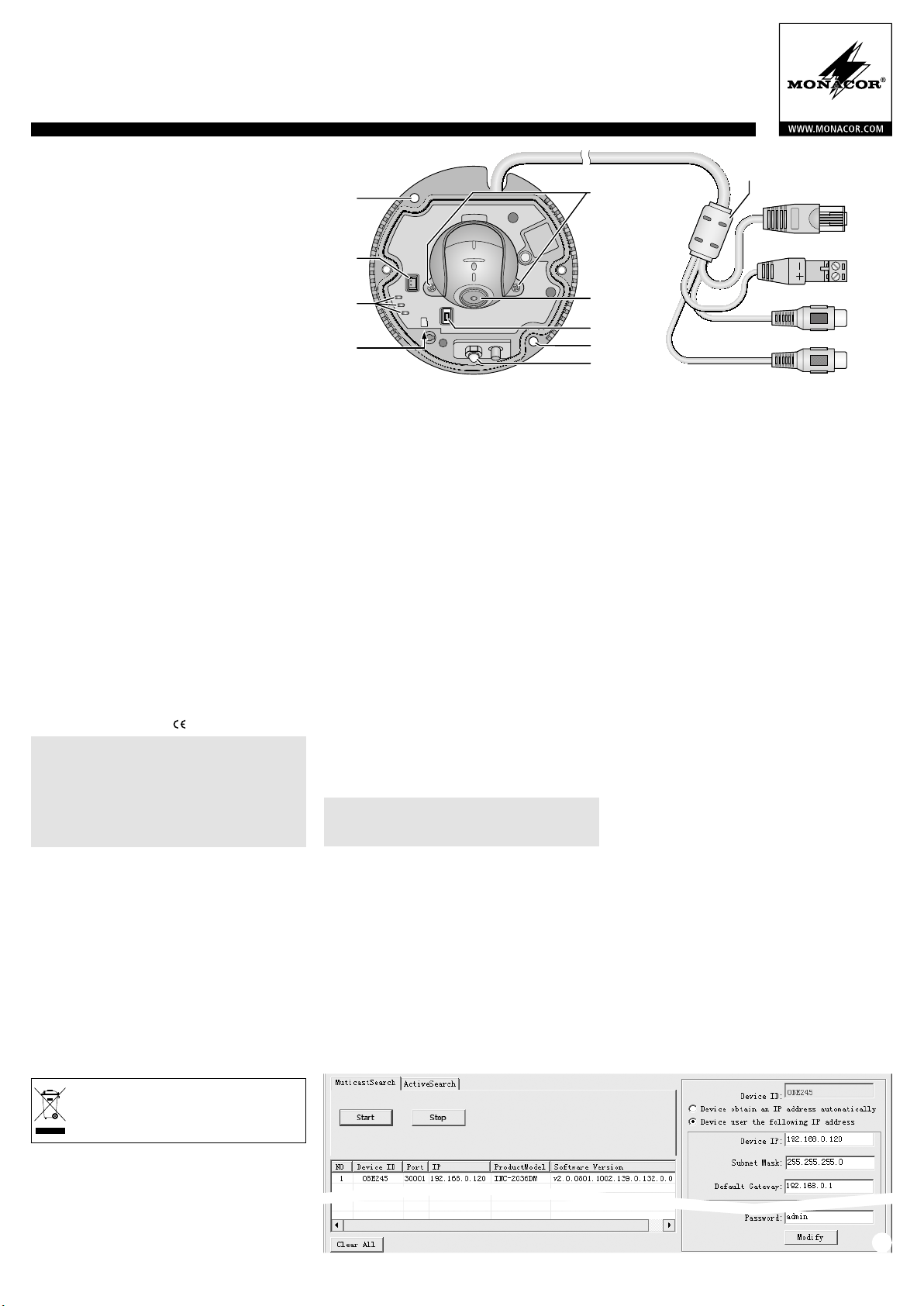
4 Kamera anschließen
Die Anschlüsse (10 – 13) und der Kabelverteiler (9)
sind nicht wetterfest. Sie müssen entsprechend geschützt werden.
1) Die Kamera über den RJ45-Stecker (10) mit einem
einzelnen Computer, einem lokalen Computernetzwerk oder, z. B. über einen Router, mit größeren Computernetzwerken (Internet) verbinden
(RJ45-Kupplung liegt bei).
Die LED NET (3) zeigt das Bestehen einer Netz-
werkverbindung an.
Hinweis: Bei einer direkten Verbindung mit einem Computer wird ggf. ein Crossover-Kabel benötigt.
2) Für die Tonübertragung über das Netzwerk kann
an die Cinch-Kupplung „AudioInput“ (12) eine
Tonquelle mit Line-Pegel (z. B. Mikrofon mit Vorverstärker) angeschlossen werden.
12V
7
6
1
Audio Input
Audio Output
5
3) Damit eine gegenseitige Kommunikation über
einen Computer möglich ist, an die Cinch-Kupplung „Audio Output“ (13) einen Kopfhörerverstärker oder eine Lautsprecher anlage anschließen.
4) Zum einfacheren Ausrichten der Kamera kann an
die Buchse VIDEO (2) ein analoger Monitor angeschlossen werden (BNC-Adapter liegt bei).
5) Soll die Kamera eigenständig Video-Aufzeichnungen durchführen, die Gehäuseabdeckung
nach Lösen der beiden Schrauben entfernen und
eine Speicherkarte vom Typ „micro SD[HC]“ (max.
32 GB) in den Schlitz (4) einsetzen (mit der abgeschrägten Ecke zur Kamera zeigend). Die Karte in
den Schlitz schieben, bis sie einrastet. Die LED SD
(3) leuchtet bei eingesetzter Karte.
Die Karte zum Entnehmen etwas hineindrücken, sodass sie ausrastet. Eine laufende Aufnahme unbedingt zuvor beenden!
Die Gehäuseabdeckung wieder dicht verschließen.
6) An die abziehbaren Schraubklemmen (11) ein stabilisiertes 12-V-Netz gerät mit einer Dauerbelastbarkeit von 1 A (z. B. PSS-1210DC) anschließen.
Dabei die Polung beachten.
Alternativ lässt sich die Kamera auch über das
Netzwerkkabel versorgen (Power over Ethernet
IEEE 802.3af).
5 Kamera in ein Netzwerk einbinden
Damit die Kamera zum Konfigurieren über einen
Computer direkt angesprochen werden kann, ist
ihre IP-Adresse vom Werk aus auf 192.168.0.120
voreingestellt.
Ist die aktuelle Adresse der Kamera nicht bekannt,
zum Finden der Kamera im Netzwerk das auf der beiliegenden CD enthaltene Programm „IPSearch.exe“
starten.
1) Um die Suche zu starten, auf der Registerkarte
„Multicast Search“ die Schaltfläche „Start“ anklicken. Die im Netzwerk gefundenen Kameras
werden in der Liste auf der linken Seite angezeigt
(☞Abb. 2).
11
12
13
➀
3 Montage
1) Um die optimale Montagestelle festzustellen, sollte ein Probebetrieb erfolgen. Dazu die Kamera
vorläufig in Betrieb nehmen (☞folgende Kapitel).
2) Mit dem beiliegenden Schlüssel die zwei Schrauben der Gehäuseabdeckung lösen und die Ab-
➁
Page 2
INC-2036 DM Bestellnummer 18.4700
ELECTRONICS FOR SPECIALISTS ELECTRONICS FOR SPECIALISTS ELECTRONICS FOR SPECIALISTS ELECTRONICS FOR SPECIALISTS ELECTRONICS FOR SPECIALISTS ELECTRONICS FOR SPECIALISTS ELECTRONICS
2) Zum Beenden der Suche auf die Schaltfläche „Stop“ klicken.
3) Die Kamera in der Liste auswählen. Auf der rechten Seite werden jetzt die
aktuellen Einstellungen dieser Kamera gezeigt.
4) Die Einstellungen nach Bedarf ändern:
IP-Adresse, Teilnetzmaske und Gateway-Adresse können statisch festgelegt
werden (Option „Device uses the following IP address“ wählen). Dabei muss
für jede Kamera eine eindeutige IP-Adresse eingegeben werden. Existiert in
dem Netzwerk ein DHCP-Server (z. B. im Router oder Netzwerk-Video rekorder),
kann dieser Einstellungen für die Kamera automatisch vornehmen ( Option
„Device obtains an IP address automatically“ wählen); die automatisch vergebenen Werte sind dann grau hinterlegt und können nicht geändert werden.
5) Auf die Schaltfläche „Modify“ klicken. Bei erfolgreicher Übertragung der
Änderungen wird die Meldung „Modify success!“ angezeigt.
6) Vor einer erneuten Suche kann die Liste über die Schaltfläche „Clear All“
gelöscht werden.
6 Kamera über einen Computer aufrufen
Die Bedienoberfläche der Kamera kann durch die Eingabe ihrer IP-Adresse in
der Adresszeile des Programms Windows Internet Explorer (IE, Version 6 oder
höher) aufgerufen werden. Dazu müssen die IP-Adressen vom Computer und
der Kamera demselben Teilnetz angehören. Es sind max. 6 gleichzeitige Zu griffe
auf die Kamera möglich.
Beim Aufruf der Kamera erscheint zunächst das Anmeldefenster. Hier die Spra-
che für die Benutzeroberfläche wählen; die folgende Beschreibung bezieht sich
auf die Einstellung „Deutsch“. Anschließend den Benutzernamen und das Passwort eingeben (Vorgabe für beide Eingaben: admin). In den Kameraeinstellungen
können später eigene Anmeldedaten festgelegt werden.
Wichtig: Gegen einen unbefugten Zu gang sollte zumindest das Passwort geändert werden.
Eine einfache Darstellung des Kamerabilds ist mit der auf vielen Computern vorhandenen Flash-Player-Erweiterung von Adobe möglich (auch auf beiliegender
CD). Für eine schnellere Bildübertragung sowie die Nutzbarkeit aller Funktionen
ist jedoch die Installation der ActiveX-Erweiterungen erforderlich. Diese werden
beim erstmaligen Klicken auf die Flash /Ac tiveX-Umschaltzeile g (☞Abb. 3) aus
der Kamera geladen. Wenn nötig, müssen dafür die Sicherheitseinstellungen des
IE so gelockert werden, dass dieser Vorgang zugelassen wird. Die Installationsdatei „webPlugins.exe“ auf dem Computer speichern, den IE schließen und die
Datei ausführen.
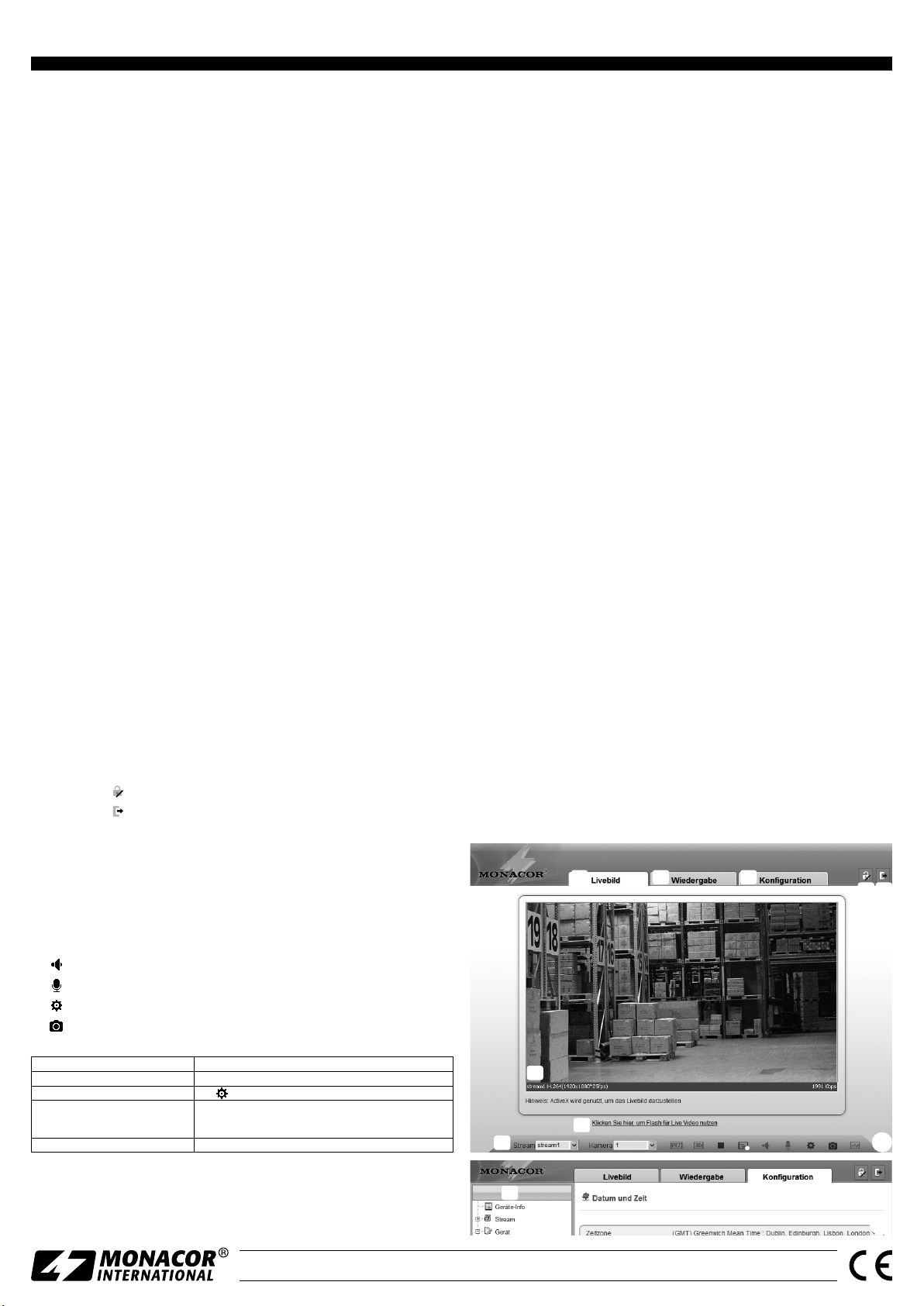
Ist die Verbindung zur Kamera aufgebaut, wird die in Abb. 3 gezeigte Ansicht
mit dem aktuellen Kamerabild angezeigt, mit folgenden Bedienmöglichkeiten:
Ansicht „Livebild“ mit Anzeige des Kamerabilds
a
Ansicht „Wiedergabe“ zum Abspielen der Aufnahmen aus der Kamera
b
Ansicht „Konfiguration“ zum Ändern der Kameraeinstellungen
c
Schaltfläche zum Ändern des Passworts
d
Schaltfläche zum Abmelden
e
Kamerabild mit Informationen zum aktuell übertragenen Stream
f
Zum Umschalten zwischen Flash-Player- und ActiveX-Nutzung für die Darstel-
g
lung des Live-Bildes auf diese Zeile klicken.
Funktionsleiste mit folgenden Funktionen
h
/ : Beenden / Starten der Bildübertragung
„Stream“: Auswahl eines Streams (zur Änderung die Übertragung eines lau-
fenden Streams mit beenden)
: Tonübertragung von der Kamera ein-/ausschalten [Audio Input (12)]
: Tonübertragung zu der Kamera ein-/ausschalten [Audio Output (13)]
: spezifische Kameraeinstellungen (z. B. Helligkeitsregelung, Spiegelung)
: Schnappschuss-Funktion zum Speichern einer Mo mentaufnahme als Bild
Das Klicken mit rechter Maustaste auf das Kamerabild zeigt folgendes Menü:
Vollbild (schließen) Vollbildansicht (beenden), alternativ: Doppelklick auf das Bild
Sensor-Einstellungen speichern
Zoom In / Out
Panorama beenden gesamtes Bild zeigen (nach Zoom In)
Zum Ändern der Einstellungen für die Kamera, über den Reiter c auf die Ansicht
„Konfiguration“ umschalten (☞Abb. 4). Am linken Rand (i) die gewünschte
Rubrik für die Einstellungen auswählen. Durch Klicken auf ⊞ lassen sich weitere
Unterrubriken anzeigen. So lässt sich z. B. unter „Gerät Datum und Zeit“ die
aktuelle Zeit für die Kamera einstellen.
Menüpunkt Funktion
wie
Hinein-/Herauszoomen
alternativ: mit Mausrad zoomen oder über dem gewünschten
Bildausschnitt einen Rahmen aufziehen
Nach dem Ändern einer Einstellung zum Speichern der Änderung auf den grünen Haken ✔ oder die Schaltfläche „übernehmen“ klicken. Zum Laden der aktuellen Einstellungen aus der Kamera auf die Schaltfläche „Aktualisierung“ klicken.
Windows ist ein registriertes Warenzeichen der Microsoft Corporation in den USA und anderen Ländern.
7 Rücksetzen der Kamera
Die Kamera kann auf ihre Werkseinstellungen zurückgesetzt werden. Dabei
gehen alle vom Anwender durchgeführten Änderungen der Kameraeinstellungen verloren.
1) Mit dem beiliegenden Schlüssel die zwei Schrauben der Gehäuseabdeckung
lösen und die Abdeckung entfernen.
2) Die Taste RESET TO DEFAULT (6) länger als 5 Sekunden drücken. Der Rück-
setzprozess startet nach dem Loslassen der Taste verzögert und kann einige
Minuten dauern.
3) Die Gehäuseabdeckung wieder dicht verschließen.
Die Kamera ist jetzt wieder auf die statische IP-Adresse 192.168.0.120 eingestellt,
der Benutzername und das Kennwort für die Anmeldung lauten: admin
8 Technische Daten
Bildabtaster: . . . . . . . . . . CMOS, 8,5 mm (1⁄3 ”)
Objektiv, Blickwinkel: . . . 1 : 1,2 /3,6 mm, 75°
Mindestbeleuchtung: . . . 0,2 lx (Farbe)
Auflösung: . . . . . . . . . . . max. 30 Bilder / s bei 1920 × 1080 Bildpunkten
Elektronischer Verschluss: 1⁄5 – ½0 000 s
Protokolle: . . . . . . . . . . . IPv4, IPv6, HTTPS, RTSP, DDNS, SMTP, SSL, ONVIF2.4,
u. a.
Kompressionsverfahren: . MPEG-4 H.264, MJPEG
Videostreaming: . . . . . . . Main 500 – 12 000 kbit /s, Sub 100 – 6000 kbit /s
Audio-Bitrate: . . . . . . . . . 64 kbit /s
Netzwerk: . . . . . . . . . . . . Ethernet 10 / 100 Mbit / s
Schutzart: . . . . . . . . . . . . IP 66
Stromversorgung: . . . . . . ⎓12 V/1 A oder PoE IEEE 802.3af
Abmessungen, Gewicht: . ⌀ 100 mm × 53 mm, 650 g
Änderungen vorbehalten.
h
f
a
g
b
c
d
i
➂
➃
e
MONACOR INTERNATIONAL GmbH & Co. KG • Zum Falsch 36 • 28307 Bremen • Germany
Copyright© by MONACOR INTERNATIONAL. All rights reserved.
A-1789.99.01.05.2017
Page 3
2
1
3
4
INC-2036 DM Order Number 18.4700
ELECTRONICS FOR SPECIALISTS ELECTRONICS FOR SPECIALISTS ELECTRONICS FOR SPECIALISTS ELECTRONICS FOR SPECIALISTS ELECTRONICS FOR SPECIALISTS ELECTRONICS
Outdoor Network Camera
These instructions are intended for installers of
video surveillance systems. Please read the in-
English
structions carefully prior to installation and keep
them for later reference.
8
9
LAN
10
1 Applications
The camera INC-2036DM is specially designed for
video surveillance systems based on computer networks. Its housing is weatherproof (IP 66); therefore,
the camera is also suited for outdoor applications.
It is equipped with a 2 megapixel image sensor and
a 3.6 mm lens. The camera features include mirror
image, masking of image areas and motion detection. In the dark, the integrated IR LED will illuminate
a surveillance zone of up to 5 m and the camera will
switch to B / W mode. The camera is provided with
an integrated web server with 2-way video streaming. For correct configuration, knowledge in network
technology is indispensable.
The camera can be operated in combination with
a network video recorder (e. g. INR-…*) or operated
independently via a web browser. It is equipped with
an audio input and an audio output so that mutual
communication via a computer will be possible. A
memory card slot allows video recording in the camera according to schedule or triggered by integrated
motion detection.
* Hint: If this camera model does not appear in the list of the
recorder used, select the ONVIF protocol.
2 Important Notes
The camera corresponds to all relevant directives of
the EU and is therefore marked with .
CAUTION When it gets dark, the infrared LED (5)
will switch on. When setting up the camera, never
look directly into the lit infrared LED at close range.
The infrared light may cause eye irritation. However,
the infrared radiation is far below the emission limit
and rated risk-free according to EN 62471.
Protect the camera against extreme temperatures
•
(admissible ambient temperature range: −20 °C to
+50 °C).
Never use aggressive detergents or chemicals
•
when cleaning the camera.
No guarantee claims for the camera and no liabil-
•
ity for any resulting personal damage or material
damage will be accepted if the camera is used for
other purposes than originally intended, if it is not
correctly connected or operated, or if it is not repaired in an expert way. Likewise, no liability will
be accepted for any data loss due to operating errors or a defect or for any consequential damage
caused by this data loss.
If the camera is to be put out of operation
definitively, take it to a local recycling plant
for a disposal which is not harmful to the
environment.
VIDEO
POWER
NET
SD
RESET TO
DEFAULT
connection cable (alternatively, guide the cable
through the rubber seal on the side of the base).
Use the holes (1) to fasten the camera base at the
mounting location.
Note: Always take into account the beam angle of the IR
LED (5) when installing the camera. Do not aim the camera
directly at the sun or other bright light sources; this may
reduce the life of the image sensor.
4) To align the camera, slightly loosen the two screws
(8) of the camera support so that it will be easier
to turn the camera (7) in the support. Then fasten
the screws again.
5) After aligning the camera, replace the housing
cover. Fasten the two screws to seal the camera
housing.
Note: To make sure that no moisture will remain inside the
camera housing, operate the camera for at least 30minutes before closing the housing.
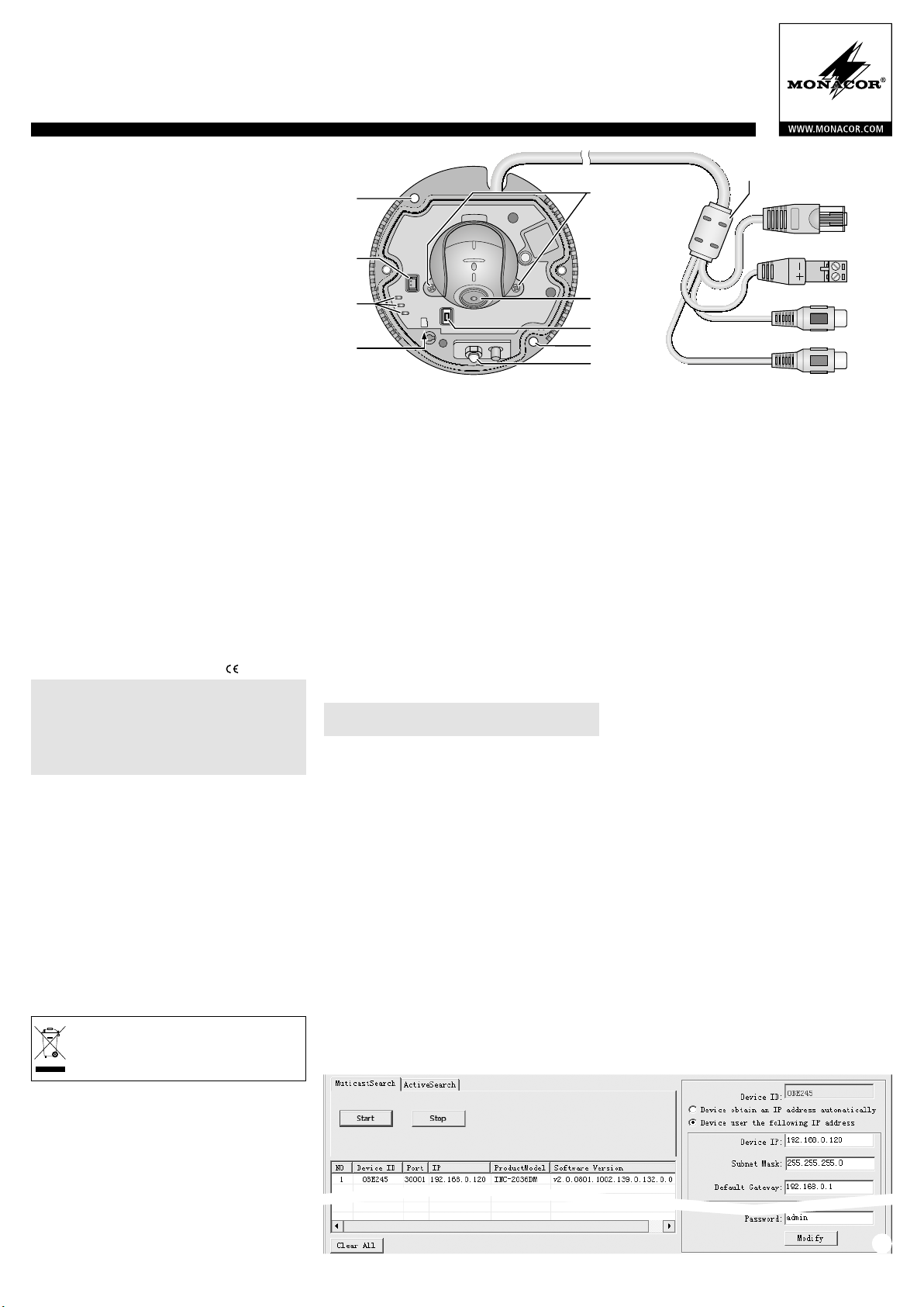
4 Connecting the Camera
The connections (10 – 13) and the cable splitter (9)
are not weatherproof; protect them accordingly.
1) Connect the camera via the RJ45 connector (10)
to an individual computer, a local computer network or, e. g. via a router, to larger computer networks (Internet). (RJ45 connector is provided.)
The LED NET (3) will indicate the network con-
nection.
Note: For direct connection to a computer, a crossover
cable may be required.
2) For audio transmission via network, connect an
audio source with line level (e. g. microphone with
preamplifier) to the RCA connector “Audio Input”
(12).
3) To allow mutual communication via a computer,
connect a headphone amplifier or a sound system
to the RCA connector “Audio Output” (13).
4) To make alignment of the camera easier, connect
an analog monitor to the jack VIDEO (2). (BNC
adapter is provided.)
12V
7
6
1
Audio Input
Audio Output
5
5) For using the camera itself for video recordings,
loosen the two screws of the housing cover, remove the cover and insert a memory card of the
type “microSD[HC]” (32 GB max.) into the slot (4),
notched corner facing the camera. Insert the card
into the slot until it engages. The LED SD (3) will
light up when a card has been inserted.
To remove the card, push the card into the slot
until it disengages. Never remove the card while a
recording is being made!
Tightly close the housing cover again.
6) Connect a regulated 12 V power supply unit with
a permanent rating of 1 A (e. g. PSS-1210DC)
to the removable screw terminals (11). Always
observe the correct polarity.
Alternatively, use the network cable (Power
over Ethernet IEEE 802.3af) to supply the camera
with power.
5 Connecting the Camera to a Network
To be able to directly address the camera for configuration, its IP address is factory-set to 192.168.0.120.
If you do not know the current address of the camera, start the program „IPSearch.exe“ from the CD
provided to find the camera in the network.
1) To start the search, click the button “Start” of
the tab „Multicast Search“. The list on the left
will show the cameras found in the network
(☞fig.2).
2) To stop the search, click the button “Stop”.
3) Select the camera from the list. The current settings of this camera can be found on the right.
4) Change the settings as required:
IP address, subnet mask and gateway address
can be defined as static values (select the option
“Device uses the following IP address”). Enter a
unique IP address for each camera. If a DHCP server
is available in the network (e. g. in the router or
network video recorder), this server will be able to
automatically make settings for the camera (select
11
12
13
➀
3 Installation
1) A test operation is recommended in order to find
the best mounting location. For this purpose, operate the camera temporarily (☞next chapters).
2) Use the key provided to loosen the two screws of
the housing cover. Remove the cover. Be careful
not to scratch the dome during installation.
3) At the mounting location (e. g. wall or ceiling),
drill two holes for fixing the camera (drilling jig
is provided) and, if necessary, drill a hole for the
➁
Page 4

INC-2036 DM Order Number 18.4700
ELECTRONICS FOR SPECIALISTS ELECTRONICS FOR SPECIALISTS ELECTRONICS FOR SPECIALISTS ELECTRONICS FOR SPECIALISTS ELECTRONICS FOR SPECIALISTS ELECTRONICS FOR SPECIALISTS ELECTRONICS
the option “Device obtains an IP address automatically”). The values assigned
automatically are highlighted in grey and cannot be changed.
5) Click the button „Modify“. After successful transmission of the modifications,
the message „Modify success!“ will appear.
6) Before you start a new search, click the button „Clear All“ to delete the list.
6 Calling up the Camera via a Computer
To call up the user interface of the camera, enter its IP address in the address
bar of the program Windows Internet Explorer (IE, version 6 or higher). The
IPaddresses of the computer and of the camera must be in the same subnet. The
number of simultaneous accesses to the camera is limited to 6.
When the camera is called up, the log-in window will appear. Select the lan-
guage for the user interface. The description below refers to English. Then enter
the user name and the password (default setting for both: admin). Individual
log-in data can be defined later in the camera settings.
Important: To prevent unauthorized access, change at least the password.
The Flash Player extension from Adobe provided on many computers (also available on the CD provided) will allow a basic display of the camera image. Faster
image transmission and availability of all functions, however, requires installation
of the ActiveX extensions. These extensions will be loaded from the camera when
the Flash/ActiveX line g (☞fig. 3) is clicked for the first time. If necessary, reduce
the security settings of the IE accordingly to allow the installation process. Save
the installation file „webPlugins.exe“ to the computer, close the IE and execute
the file.
When the connection to the camera has been established, the view with the current camera image (fig. 3) will be displayed. The following options are available:
View „Live Video“ with display of camera image
a
View „Playback“ to replay the recordings from the camera
b
View „Configuration“ to change the camera settings
c
Button to change the password
d
Button to log out
e
Camera image with information on the stream currently transmitted
f
Click this line to switch between use of Flash Player and ActiveX for display of
g
the live image
Toolbar with the following functions:
h
/ : Stop/Start of image transmission
“Stream”: Selection of a stream (when selecting a different stream, click to
stop the transmission of the current stream)
: Activation / Deactivation of audio transmission from the camera [Audio
Input (12)]
: Activation/Deactivation of audio transmission to the camera [Audio Out-
put (13)]
: Specific camera settings (e. g. brightness control, mirror image)
: Snapshot function to save a snapshot as an image file
When the camera image is clicked with the right mouse button, the following
menu will appear:
Full Screen (Exit Full Screen) full-screen image (exit), alternatively: double-click the image
Sensor
Zoom In / Out
Restore Panorama display of the entire image (after zooming in)
To change the settings for the camera, select the tab c and go to the view
„Configuration“ (☞ fig. 4). On the left (i), select the desired category for
the settings. To show additional subcategories, click ⊞. To set, for example, the
current time for the camera, go to “Device Date and Time”.
button “Apply”. To load the current settings from the camera, click the button
“Refresh”.
Windows is a registered trademark of Microsoft Corporation in the USA and other countries.
Menu item Function
like
zooming in / zooming out
alternatively: use the scroll wheel to zoom in / out or drag the
mouse to select the desired image section
To save a setting that has been changed, click the green check mark ✔ or the
7 Resetting the Camera
When the camera is reset to its factory settings, any changes the user has made
to the camera settings will be lost.
1) Use the key provided to loosen the two screws of the housing cover. Remove
the cover.
2) Keep the button RESET TO DEFAULT (6) pressed for more than 5seconds.
When the button is released, resetting will start with a delay and may take a
few minutes.
3) Tightly close the housing cover again.
The camera is reset to the static IP address 192.168.0.120. The default user name
and the password for log-in is: admin.
8 Specifications
Image sensor: . . . . . . . . . CMOS, 8.5 mm (1⁄3 ”)
Lens, viewing angle: . . . . 1 : 1.2 /3.6 mm, 75°
Minimum illumination: . . 0.2 lx (colour)
Resolution: . . . . . . . . . . . 30 frames max. per second with 1920 × 1080 pixels
Electronic shutter: . . . . . . 1⁄5 – ½0 000 s
Protocols: . . . . . . . . . . . . IPv4, IPv6, HTTPS, RTSP, DDNS, SMTP, SSL, ONVIF2.4,
etc.
Compression: . . . . . . . . . MPEG-4 H.264, MJPEG
Video streaming: . . . . . . . Main 500 – 12 000 kbit /s, Sub 100 – 6000 kbit /s
Audio bit rate: . . . . . . . . 64 kbit / s
Network: . . . . . . . . . . . . Ethernet 10 / 100 Mbit / s
IP rating: . . . . . . . . . . . . . IP 66
Power supply: . . . . . . . . . ⎓12 V/1 A or PoE IEEE 802.3af
Dimensions, weight: . . . . ⌀ 100 mm × 53 mm, 650 g
Subject to technical modification.
h
f
a
g
b
c
d
e
➂
i
MONACOR INTERNATIONAL GmbH & Co. KG • Zum Falsch 36 • 28307 Bremen • Germany
Copyright© by MONACOR INTERNATIONAL. All rights reserved.
➃
A-1789.99.01.05.2017
Page 5

2
1
3
4
INC-2036 DM Référence numérique 18.4700
ELECTRONICS FOR SPECIALISTS ELECTRONICS FOR SPECIALISTS ELECTRONICS FOR SPECIALISTS ELECTRONICS FOR SPECIALISTS ELECTRONICS FOR SPECIALISTS ELECTRONICS
Caméra réseau pour l’extérieur
Cette notice s’adresse aux installateurs de systèmes de surveillance vidéo. Veuillez lire la pré-
Français
sente notice avec attention avant l’installation
et conservez-la pour pouvoir vous y reporter
ultérieurement.
1 Possibilités d’utilisation
La caméra INC-2036DM est spécialement conçue
pour une utilisation dans des installations de surveillance vidéo basées sur des réseaux informatiques.
Grâce à son boîtier étanche (type de protection
IP 66), elle est également adaptée à une utilisation
en extérieur. Elle est dotée d’un capteur d’image
2 mégapixels et d’un objectif 3,6 mm et propose
entre autres, une visualisation en image miroir, un
masquage de zones d’images et une détection de
mouvements. Dans la pénombre, la LED infrarouge
intégrée éclaire la zone de surveillance jusqu’à 5 m ;
la caméra commute automatiquement en mode noir
et blanc. La caméra dispose d’un serveur web intégré
avec streaming vidéo × 2. Pour une installation correcte, des connaissances en technologie réseau sont
indispensables.
La caméra peut être utilisée, en combinaison avec
un enregistreur vidéo réseau (par exemple INR-…*)
ou seule via un navigateur internet. Elle dispose
d‘une entrée audio et d‘une sortie audio pour qu‘une
communication réciproque via un ordinateur soit
possible. Un emplacement pour une carte mémoire
permet un enregistrement vidéo dans la caméra,
déclenché selon un planning ou par la détection
intégrée de mouvement.
* Conseil : Si le modèle de caméra n’existe pas dans la liste de
l’enregistreur utilisé, sélectionnez le protocole ONVIF.
2 Conseils importants d’utilisation
La caméra répond à toutes les directives nécessaires
de l’Union européenne et porte donc le symbole .
ATTENTION La LED infrarouge (5) s’allume dans la
pénombre. Ne regardez jamais directement la LED
allumée de proximité. La lumière infrarouge peut
engendrer des irritations des yeux. Le rayonnement infrarouge est cependant loin du seuil limite
d’émission et considéré sans risque selon la norme
EN 62471.
Protégez la caméra des températures extrêmes
•
(plage de température de fonctionnement autorisée : −20 °C à +50 °C).
Pour le nettoyage, n’utilisez pas de produits
•
chimiques ou de détergents agressifs.
Nous déclinons toute responsabilité en cas de
•
dommages corporels ou matériels résultants si la
caméra est utilisée dans un but autre que celui
pour lequel elle a été conçue, si elle n’est pas correctement branchée ou utilisée ou si elle n’est pas
réparée par une personne habilitée; en outre, la
garantie deviendrait caduque. De même, notre
responsabilité ne saurait être engagée en cas de
pertes de données et leurs conséquences, causées
par une mauvaise utilisation ou un défaut.
Lorsque la caméra est définitivement retirée
du service, vous devez la déposer dans une
usine de recyclage de proximité pour contribuer à son élimination non polluante.
VIDEO
POWER
NET
SD
RESET TO
DEFAULT
3 Montage
1) Effectuez un test de fonctionnement afin de définir le lieu optimal de montage. Pour ce faire,
mettez temporairement la caméra en fonction
(☞chapitres suivants).
2) Avec la clé livrée, desserrez les deux vis du couvercle du boîtier et retirez le couvercle. Veillez à ce
que la coupole ne soit pas rayée lors du montage.
3) Sur le lieu de montage (par exemple mur ou plafond), percez 2 trous pour fixer la caméra (gabarit
de perçage livré) et, si besoin, percez un trou pour
le câble de branchement (le câble peut également
passer sur le côté par le joint caoutchouc d‘étanchéité). Vissez le socle sur les trous (1).
Remarque : Lors du montage, faites attention au sens de
rayonnement de la LED IR (5). Evitez de diriger la caméra
directement vers des sources puissantes de lumière (par
exemple soleil) ; cela pourrait réduire la durée de vie du
capteur d‘image.
4) Pour orienter la caméra, desserrez les deux vis(8)
du support de caméra pour que la caméra (7)
puisse tourner facilement. Revissez ensuite.
5) Une fois l‘orientation de la caméra réglée, repositionnez le couvercle du boîtier et fermez le boîtier
de caméra avec les deux vis de manière étanche.
Remarque : Pour que l‘humidité ne reste pas dans le
boîtier de la caméra, il faut faire fonctionner la caméra
pendant 30 minutes au moins avant de fermer le boîtier.
4 Branchement de la caméra
Les connexions (10 – 13) et le répartiteur de câble
(9) ne sont pas étanches. Vous devez les protéger
en conséquence.
1) Reliez la caméra via la fiche RJ45 (10) à un ordinateur individuel, un réseau local d’ordinateurs ou,
par exemple, via un routeur, à des réseaux d’ordinateurs (internet) plus importants (fiche RJ45
femelle livrée).
La LED NET (3) indique l‘existence d‘une
connexion réseau.
Remarque : Pour une connexion directe avec un ordinateur, un cordon Crossover est éventuellement nécessaire.
8
7
6
1
5
2) Pour la transmission audio via le réseau, on peut
relier une source audio avec niveau ligne (par
exemple microphone avec préamplificateur) à la
fiche RCA femelle «Audio Input» (12).
3) Pour qu‘une communication réciproque via un
ordinateur soit possible, reliez un amplificateur
casque ou une installation HP à la fiche RCA
femelle «Audio Output» (13).
4) Pour orienter plus facilement la caméra, on peut
brancher un moniteur analogique à la prise VIDEO
(2) (adaptateur BNC livré).
5) Si la caméra doit faire des enregistrements vidéo
de manière indépendante, desserrez les deux vis,
retirez le couvercle du boîtier et insérez une carte
mémoire de type «microSD[HC]» (32 GO max.)
dans la fente (4) (avec le coin oblique dirigé vers
la caméra). Poussez la carte dans la fente jusqu‘à
ce qu‘elle s‘enclenche. La LED SD (3) brille lorsque
la carte est insérée.
Pour la retirer, appuyez sur la carte jusqu‘à ce
qu‘elle se désenclenche. Arrêtez impérativement
tout enregistrement avant que la carte soit retirée!
Refermez le couvercle du boîtier et veillez à l‘étanchéité.
6) Reliez un bloc secteur 12 V stabilisé avec une puissance continue de 1 A (par exemple PSS-1210DC)
aux bornes à vis amovibles (11). Veillez à respecter
la polarité.
A la place, la caméra peut être alimentée via le
câble réseau (Power over Ethernet IEEE 802.3af).
5 Intégrer la caméra dans un réseau
Pour que la caméra puisse être directement adressée
via un ordinateur pour la configuration, son adresse
IP est réglée, en usine, sur 192.168.0.120.
Si l’adresse actuelle de la caméra n’est pas connue,
démarrez le programme «IPSearch.exe», présent sur
le CD, pour trouver la caméra dans le réseau.
1) Pour démarrer la recherche, cliquez sur le bouton
«Start» de l‘onglet «Multicast Search». Les caméras trouvées dans le réseau sont affichées dans la
liste sur le côté gauche (☞schéma 2).
9
LAN
12V
Audio Input
Audio Output
10
11
12
13
➀
CARTONS ET EMBALLAGE
PAPIER À TRIER
➁
Page 6

INC-2036 DM Référence numérique 18.4700
ELECTRONICS FOR SPECIALISTS ELECTRONICS FOR SPECIALISTS ELECTRONICS FOR SPECIALISTS ELECTRONICS FOR SPECIALISTS ELECTRONICS FOR SPECIALISTS ELECTRONICS FOR SPECIALISTS ELECTRONICS
2) Pour terminer la recherche, cliquez sur le bouton «Stop».
3) Sélectionnez la caméra dans la liste. Les réglages actuels de la caméra sont
affichés maintenant sur le côté droit.
4) Si besoin, modifiez les réglages :
L’adresse IP, le masque sous-réseau et l’adresse Gateway peuvent être déterminées de manière statique (sélectionnez l’option «Device uses the following
IPaddress»). Il faut une adresse IP unique pour chaque caméra. Si dans le
réseau, il existe un serveur DHCP (par exemple dans le routeur ou l’enregistreur vidéo réseau), il peut effectuer automatiquement les réglages pour la
caméra (sélectionnez l’option «Device obtains an IP address automatically»);
les valeurs attribuées automatiquement apparaissent sur un fond gris et ne
peuvent pas être modifiées.
5) Cliquez sur le bouton «Modify». Lorsque la transmission des modifications est
réussie, le message «Modify success!» s’affiche.
6) La liste peut être effacée avant une nouvelle recherche via le bouton «Clear
All».
6 Appeler une caméra via un ordinateur
L’interface utilisateur de la caméra peut être appelée en saisissant son adresse
IP dans la barre d’adresse du programme Windows Internet Explorer (IE, Version
6 ou supérieur). Pour ce faire, il faut que les adresses IP de l’ordinateur et de la
caméra appartiennent au même sous-réseau. 6 accès simultanés au plus à la
caméra sont possibles.
Lorsque vous appelez la caméra, la fenêtre d‘ouverture de session s’affiche en
premier. Sélectionnez la langue pour l’interface utilisateur ; la description suivante
se réfère au réglage «English». Ensuite, saisissez le nom utilisateur et le mot de
passe (préréglage pour les deux saisies : admin). Dans les réglages de caméra, on
peut définir ultérieurement des données propres.
Important : Modifiez au moins le mot de passe contre tout accès non autorisé.
Une visualisation simple de l’image de caméra est possible avec l’extension Flash
Player d‘Adobe existante sur de nombreux ordinateurs (également sur le CD livré).
Pour une transmission plus rapide des images et pour l’utilisation de toutes les
fonctions, l’installation des extensions ActiveX est indispensable. Elles sont chargées depuis la caméra lorsque vous cliquez pour la première fois sur la ligne
Flash /ActiveX g (☞schéma 3). Si besoin, il faut réduire les réglages de sécurité de IE pour que le processus soit autorisé. Mémorisez le fichier d’installation
«webPlugins.exe» sur l’ordinateur, fermez IE, et exécutez le fichier.
Si la connexion à la caméra est établie, la visualisation indiquée sur le schéma3
avec l’image actuelle de la caméra s’affiche, avec les possibilités suivantes d’utilisation :
Visualisation «Live Video» avec affichage de l’image de la caméra
a
Visualisation «Playback» pour reproduire les enregistrements de la caméra
b
Visualisation «Configuration» pour modifier les réglages de caméra
c
Bouton pour modifier le mot de passe
d
Bouton pour se déconnecter
e
Image de la caméra avec des informations sur le stream actuellement transmis
f
Pour commuter entre utilisation Flash Player et ActiveX pour la visualisation de
g
l‘image Live, cliquez sur cette ligne.
Barre de fonctions avec les fonctions suivantes
h
/ : Quitter / Démarrer la transmission d’images
«Stream»: sélection d’un stream (pour modifier la transmission d’un stream en
cours, quittez avec )
: Activation / Désactivation de la transmission audio depuis la caméra [Audio
Input (12)]
: Activation / Désactivation de la transmission audio vers la caméra [Audio
Output (13)]
: Réglages spécifiques de caméra (par exemple réglage luminosité, mode
miroir)
: Fonction capture pour mémoriser un instantané comme image
Par un clic droit de la souris sur l’image de la caméra, le menu suivant s’affiche :
Point menu Fonction
Full Screen (Exit Full Screen)
Sensor
Zoom In / Out
Restore Panorama Afficher l’image entière (après Zoom In)
Visualisation image plein écran (quitter),
Alternative : double clic sur l’image
comme
Zoom avant / arrière
Alternative : avec la molette de la souris, zoomez ou tirez un
cadre sur la section d’image voulue.
Pour modifier les réglages pour la caméra, commutez sur la visualisation «Configuration» (☞schéma 4) via l‘onglet c. Sélectionnez la rubrique voulue pour
les réglages dans le bord gauche (i). En cliquant sur ⊞, vous pouvez afficher
des sous-rubriques supplémentaires. Ainsi, on peut régler, par exemple l’heure
actuelle pour la caméra via «Device Date and Time».
Une fois le réglage modifié, cliquez sur la coche verte ✔ ou cliquez sur le bouton «Apply» pour mémoriser la modification. Pour charger les réglages actuels
depuis la caméra, cliquez sur le bouton «Refresh».
Windows est une marque déposée de Microsoft Corporation aux Etats-Unis et dans les autres pays.
7 Réinitialisation de la caméra
La caméra peut être réinitialisée sur ses réglages usine, mais toutes les modifications des différents réglages de caméras effectuées par l‘utilisateur sont perdus.
1) Avec la clé livrée, desserrez les deux vis du couvercle du boîtier et retirez le
couvercle.
2) Maintenez la touche RESET TO DEFAULT (6) enfoncée plus de 5 secondes. Une
fois que la touche est relâchée, le processus de réinitialisation démarre avec
une temporisation et peut durer quelques minutes.
3) Replacez le couvercle pour refermer le boîtier et veillez à l‘étanchéité.
La caméra est à nouveau réglée sur l’adresse IP statique 192.168.0.120 ; le nom
utilisateur et le mot de passe pour la connexion sont : admin
8 Caractéristiques techniques
Capteur image : . . . . . . . CMOS, 8,5 mm (1⁄3 ”)
Objectif, angle : . . . . . . . 1 : 1,2 /3,6 mm, 75°
Luminosité minimale : . . . 0,2 lx (couleur)
Résolution : . . . . . . . . . . . 30 images / s max. pour 1920 × 1080 points
Obturation électronique : 1⁄5 – ½0 000 s
Protocoles : . . . . . . . . . . . IPv4, IPv6, HTTPS, RTSP, DDNS, SMTP, SSL, ONVIF2.4,
et autres
Processus compression : . MPEG-4 H.264, MJPEG
Streaming vidéo : . . . . . . Main 500 – 12 000 kbit /s, Sub 100 – 6000 kbit /s
Débit binaire audio : . . . . 64 kbits /s
Réseau : . . . . . . . . . . . . . Ethernet 10 / 100 Mbit / s
Type protection : . . . . . . . IP 66
Alimentation : . . . . . . . . . ⎓12 V/1 A ou PoE IEEE 802.3af
Dimensions, poids : . . . . . ⌀ 100 mm × 53 mm, 650 g
Tout droit de modification réservé.
h
f
a
g
b
c
d
i
➂
➃
e
MONACOR INTERNATIONAL GmbH & Co. KG • Zum Falsch 36 • 28307 Bremen • Germany
Copyright© by MONACOR INTERNATIONAL. All rights reserved.
A-1789.99.01.05.2017
Page 7

2
1
3
4
INC-2036 DM Codice 18.4700
ELECTRONICS FOR SPECIALISTS ELECTRONICS FOR SPECIALISTS ELECTRONICS FOR SPECIALISTS ELECTRONICS FOR SPECIALISTS ELECTRONICS FOR SPECIALISTS ELECTRONICS
Telecamera di rete per esterni
Queste istruzioni sono rivolte agli installatori di
impianti di sorveglianza video. Vi preghiamo di
Italiano
leggerle attentamente prima dell’installazione e
di conservarle per un uso futuro.
8
9
LAN
10
1 Possibilità d’impiego
La telecamera INC-2036DM è stata realizzata specialmente per l’impiego in impianti di sorveglianza video
sulla base di reti con computer. Grazie al contenitore
resistente alle intemperie (grado di protezione IP 66)
è adatta anche per l’installazione all’esterno. È equipaggiata con un sensore ottico di 2 megapixel e con
un obiettivo di 3,6 mm e offre, fra le altre cose, lo
specchiamento delle immagini, il mascheramento di
zone dell’immagine e il riconoscimento di movimento. All’oscurità, il LED infrarosso integrato illumina la
zona da sorvegliare fino a 5 m, e la telecamera passa
al funzionamento in bianco / nero. La telecamera dispone di un webserver integrato con videostreaming
duplice. Per l’installazione corretta sono richieste assolutamente delle conoscenze di network.
La telecamera può essere usata con un videoregistratore di rete (p. es. INR-…*) oppure autonomamente tramite un webbrowser. Dispone di un
ingresso audio e di un’uscita audio che permette la
comunicazione reciproca per mezzo di un computer.
Con lo slot per una scheda di memorie si possono
effettuare delle registrazioni video nella telecamera,
attivate dal timer oppure dal riconoscimento di movimento integrato.
* Un consiglio: Se il modello della telecamera non è presente nell’elenco del registratore usato conviene scegliere il
protocollo ONVIF.
2 Avvertenze importanti per l’uso
La telecamera è conforme a tutte le direttive rilevanti
dell’UE e pertanto porta la sigla .
ATTENZIONE All’oscurità si attiva il LED IR (5).
Durante l’installazione della telecamera, non guardare da vicino direttamente nel LED IR acceso. La
luce infrarossa può irritare gli occhi. Tuttavia, la
radiazione IR è largamente inferiore al valore limite
dell’emissione, e secondo EN 62471 è considerata
senza rischio.
Proteggere la telecamera da temperature estreme
•
(temperatura d’esercizio ammessa −20 °C a +50 °C).
Per la pulizia non usare detergenti aggressivi o pro-
•
dotti chimici.
Nel caso d’uso improprio, di collegamenti sbagliati,
•
d’impiego scorretto o di riparazione non a regola
d’arte della telecamera, non si assume nessuna
responsabilità per eventuali danni consequenziali a
persone o a cose e non si assume nessuna garanzia
per la telecamera. Nello stesso modo non si assume
nessuna responsabilità per la perdita di dati e per
i relativi danni consequenziali causati da impiego
sbagliato o da un difetto della telecamera.
Se si desidera eliminare la telecamera definitivamente, consegnarla per lo smaltimento
ad un’istituzione locale per il riciclaggio.
3 Montaggio
1) Per stabilire il punto ottimale per il montaggio
conviene fare delle prove. Per fare ciò mettere
in funzione momentaneamente la telecamera
(☞capitoli successivi).
2) Con la chiave in dotazione allentare le due viti
della copertura del contenitore e togliere il coper-
VIDEO
POWER
NET
SD
RESET TO
DEFAULT
chio. Durante il montaggio fare attenzione a non
graffiare la cupola.
3) Al punto di montaggio (p. es. parete o soffitto)
applicare due fori per il fissaggio della telecamera
(una relativa dima è in dotazione) e eventualmente anche un foro per il cavo di collegamento (in
alternativa, il cavo può essere fatto passare lateralmente attraverso la guarnizione di gomma).
Avvitare lo zoccolo della telecamera con i fori (1).
N. B.: Durante il montaggio della telecamera considerare
l’angolo d’irradiazione del LED IR (5). Da evitare l’orientamento della telecamera verso fonti forti di luce (p. es.
il sole) perché ciò potrebbe ridurre la durata del sensore
ottico.
4) Per orientare la telecamera allentare leggermente le due viti (8) del supporto della telecamera
in modo che la telecamera (7) si possa girare più
facilmente. Quindi stringere nuovamente le viti.
5) Dopo l’orientamento della telecamera rimettere il
suo coperchio e chiudere bene il contenitore per
mezzo delle due viti.
N. B.: Per escludere che l’umidità esistente rimanga nel
contenitore della telecamera, la telecamera dovrebbe
rimanere in funzione per non meno di 30 minuti prima
della chiusura del contenitore.
4 Collegare la telecamera
I contatti (10 – 13) e il ripartitore dei cavi (9) non
sono resistenti alle intemperie. Pertanto, devono
essere protetti in modo adeguato.
1) Per mezzo del connettore RJ45 (10), collegare la
telecamera con un computer singolo, con una rete
locale di computer oppure, per esempio tramite
un router, con grandi reti con computer (Internet)
(una presa RJ45 è in dotazione).
Il LED NET (3) segnala la presenza della connes-
sione con una rete.
N. B.: In caso di collegamento diretto con un computer
potrebbe essere necessario un cavo crossover.
2) Per la trasmissione audio tramite la rete è possibile
collegare alla presa RCA “Audio Input” (12) una
12V
7
6
1
Audio Input
Audio Output
5
fonte audio con livello Line (p es. microfono con
preamplificatore).
3) Per rendere possibile una comunicazione reciproca tramite un computer, collegare alla presa RCA
“Audio Output” (13) un amplificatore per cuffie
oppure un impianto di altoparlanti.
4) Per semplificare l’orientamento della telecamera,
alla presa VIDEO (2) si può collegare un monitor
analogico (un adattatore BNC è in dotazione).
5) Se la telecamera deve fare delle registrazioni video
in modo autonomo, togliere la copertura della telecamera dopo aver allentato le due viti, e inserire nello slot (4) una scheda di memoria del tipo
“micro SD[HC]” (max. 32 GB) (l’angolo smussato
rivolto verso la telecamera). Spingere la scheda
nello slot fino allo scatto. Il LED SD (3) si accende
con la scheda inserita.
Per togliere la scheda spingerla leggermente
indentro per sbloccarla. Prima, si deve terminare
assolutamente una registrazione in corso!
Richiudere bene la copertura del contenitore.
6) Ai morsetti staccabili (11) collegare un alimentatore stabilizzato di 12 V con potenza continua
di 1 A (p. es. PSS-1210DC) rispettando la corretta
polarità.
In alternativa, la telecamera può essere alimentata anche attraverso il cavo rete (Power over
Ethernet IEEE 802.3af).
5 Inserire la telecamera in una rete
Affinché la telecamera possa essere messa in contatto diretta con un computer per la configurazione,
il suo indirizzo IP è preimpostato dalla fabbrica con
192.168.0.120.
Se l’indirizzo attuale della telecamera non è noto, per
trovare la telecamera nella rete avviare il programma
“IPSearch.exe” contenuto sul CD in dotazione.
1) Per avviare la ricerca, sulla scheda “Multicast
Search” cliccare sul pulsante “Start”. Sul lato
sinistro, l’elenco indica le telecamere trovate nella
rete (☞Fig. 2).
11
12
13
➀
➁
Page 8

INC-2036 DM Codice 18.4700
ELECTRONICS FOR SPECIALISTS ELECTRONICS FOR SPECIALISTS ELECTRONICS FOR SPECIALISTS ELECTRONICS FOR SPECIALISTS ELECTRONICS FOR SPECIALISTS ELECTRONICS FOR SPECIALISTS ELECTRONICS
2) Per terminare la ricerca cliccare sul pulsante “Stop”.
3) Scegliere la telecamera dall’elenco. Sul lato destro si vedono ora le impostazioni attuali di quella telecamera.
4) Modificare le impostazioni secondo necessità:
L’indirizzo IP, la maschera di sottorete e l’indirizzo gateway possono essere
stabiliti in modo statico (scegliere l’opzione “Device uses the following IP address”). In questo caso, a ogni telecamera si deve dare un indirizzo IP univoco.
Se nella rete esiste un server DHCP (p. es. nel router o nel videoregistratore di
rete), questi può eseguire le impostazioni per la telecamera in modo automatico (scegliere l’opzione “Device obtains an IP address automatically”); i valori
determinati automaticamente hanno un sottofondo grigio e non possono
essere modificati.
5) Cliccare sul pulsante “Modify”. Se le modifiche hanno avuto successo, si vede
il messaggio “Modify success!”.
6) Prima di una nuova ricerca, con il pulsante “Clear All” si può cancellare l’elenco.
6 Attivare la telecamera da un computer
L’interfaccia utente della telecamera può essere attivata digitando il suo indirizzo IP nella riga degli indirizzi del programma Windows Internet Explorer
(IE, versione 6 o maggiore). In questo caso, gli indirizzi IP del computer e della
telecamera devono essere della stessa sottorete. Sono possibili al massimo
6accessi contemporanei alla telecamera.
Attivando la telecamera, si vede all’inizio la finestra del login dove si sceglie la
lingua per l’interfaccia utente; la descrizione seguente si riferisce all’impostazione
“English”. Quindi digitare il nome utente e la password (per entrambi è preimpostato: admin). Nelle impostazioni della telecamera si possono determinare più
tardi i propri dati per il login.
Importante: Per proteggersi contro l’accesso non autorizzato si dovrebbe cambiare per lo
meno la password.
Una rappresentazione semplice dell’immagine della telecamera è possibile con
l’estensione del Flash-player di Adobe presente su molti computer (anche sul CD
in dotazione). Per una trasmissione più veloce dell’immagine e per poter utilizzare tutte le funzioni è richiesta tuttavia l’installazione delle estensioni ActiveX.
Queste vengono caricate dalla telecamera al momento del primo clic sulla riga
di cambio Flash /Active (☞Fig. 3). Se necessario occorre allentare le impostazioni
di sicurezza dell’IE in modo che questa procedura venga ammessa. Salvare sul
computer il file d’installazione “webPlugins.exe”, chiudere l’IE e eseguire il file.
Se la connessione con la telecamera è stabile, si vede l’immagine attuale della
telecamera come rappresentata in fig. 3 e con le seguenti possibilità di comando:
Visione “Live Video” con l’immagine della telecamera
a
Visione “Playback” per riprodurre le registrazioni dalla telecamera
b
Visione “Configuration” per modificare le impostazioni della telecamera
c
Pulsante per modificare la password
d
Pulsante per il logout
e
Immagine della telecamera con informazioni sullo stream attualmente tra-
f
smesso
Per cambiare fra Flash-Player e ActiveX per la rappresentazione dell’immagine
g
dal vivo, cliccare su questa riga.
Barra degli strumenti con le seguenti funzioni
h
/ : Termine /avvio della trasmissione dell’immagine
“Stream”: Selezione di uno stream (per una modifica terminare con la tra-
smissione di uno stream in corso)
: Attivare /disattivare la trasmissione audio dalla telecamera
[Audio Input (12)]
: Attivare /disattivare la trasmissione audio verso la telecamera
[Audio Output (13)]
: Impostazioni specifiche della telecamera (p. es. regolazione dell’illumina-
zione, rispecchiamento)
: Funzione registrazione istantanea per memorizzare una ripresa momen-
tanea come immagine
Cliccando con il tasto destro del mouse sull’immagine della telecamera si vede
il seguente menu:
Voce del menu Funzione
Full Screen (Exit Full Screen)
Sensor
Zoom In / Out
Restore Panorama Mostrare l’immagine intera (dopo zoom In)
(Terminare) la visione a schermo intero,
in alternativa: doppio clic sull’immagine
come
Zoom in / out
In alternativa: zoomare con il ruotino del mouse oppure
trarre una cornice sul settore richiesto dell’immagine
Per modificare le impostazioni per la telecamera, tramite il cavalierino c passare
alla vista “Configuration” (☞Fig. 4). Sul bordo sinistro (i) selezionare la rubrica
desiderata per le impostazioni. Cliccando su ⊞ si possono visualizzare ulteriori
sottorubriche. Per esempio, con “Device Date and Time” si può impostare l’ora
attuale per la telecamera.
Dopo la modifica di un’impostazione e per salvare la modifica cliccare sul
segno verde di spunta ✔ oppure sul pulsante “Apply”. Per caricare le impostazioni
attuali dalla telecamera, cliccare sul pulsante “Refresh”.
Windows è un marchio registrato della Microsoft Corporation negli USA e in altre nazioni.
7 Reset della telecamera
È possibile resettare la telecamera alle impostazioni della fabbrica. In questo caso,
tutte le modifiche delle impostazioni effettuate dall’utente vanno perse.
1) Con la chiave in dotazione allentare le due viti della copertura del contenitore
e togliere il coperchio.
2) Premere per più di 5 secondi il tasto RESET TO DEFAULT (6). Il procedimento di
reset si avvia in ritardo dopo aver lasciato il tasto e può impiegare alcuni minuti.
3) Richiudere bene la copertura del contenitore.
Ora, la telecamera è nuovamente impostata con l’indirizzo IP statico
192.168.0.120, il nome utente e la password per il login sono: admin
8 Dati tecnici
Sensore ottico: . . . . . . . . CMOS, 8,5 mm (1⁄3 ”)
Obiettivo, angolo visivo: . 1 : 1,2 /3,6 mm, 75°
Illuminazione minima: . . . 0,2 lx (colore)
Risoluzione: . . . . . . . . . . max. 30 imm. / s con 1920 × 1080 pixel
Otturatore elettronico: . . 1⁄5 – ½0 000 s
Protocolli: . . . . . . . . . . . . IPv4, IPv6, HTTPS, RTSP, DDNS, SMTP, SSL, ONVIF2.4,
et. al.
Compressione immagini: . MPEG-4 H.264, MJPEG
Videostreaming: . . . . . . . Main 500 – 12 000 kbit /s, Sub 100 – 6000 kbit /
g
Bitrate audio: . . . . . . . . . 64 kbit /s
Network: . . . . . . . . . . . . Ethernet 10 / 100 Mbit / s
Grado di protezione: . . . . IP 66
Alimentazione: . . . . . . . . ⎓12 V/1 A opp. PoE IEEE 802.3af
Dimensioni, peso: . . . . . . ⌀ 100 mm × 53 mm, 650 g
Con riserva di modifiche tecniche.
h
f
a
g
b
c
i
d
➂
➃
e
MONACOR INTERNATIONAL GmbH & Co. KG • Zum Falsch 36 • 28307 Bremen • Germany
Copyright© by MONACOR INTERNATIONAL. All rights reserved.
A-1789.99.01.05.2017
 Loading...