

Page 1
ELECTRONICS FOR SPECIALISTS ELECTRONICS FOR SPECIALISTS ELECTRONICS FOR SPECIALISTS ELECTRONICS FOR SPECIALISTS
BEDIENUNGSANLEITUNG
INSTRUCTION MANUAL
Netzwerk-Wärmebildkamera
Thermal Imaging Network Camera
INC-1500 THERM
Bestellnummer • Order Number 18.0135
Page 2
2
RS485+
RS485−
12V
LAN
Audio Input
Audio Output
Alarm
OUT COM1
OUT1
OUT COM2
OUT2
IN COM
IN1
IN2
2
4
1
6
7
8
9
10
12
11
5
3
54
14
13
15
1816 17
“TOP”
“TOP”
14
17
①
②
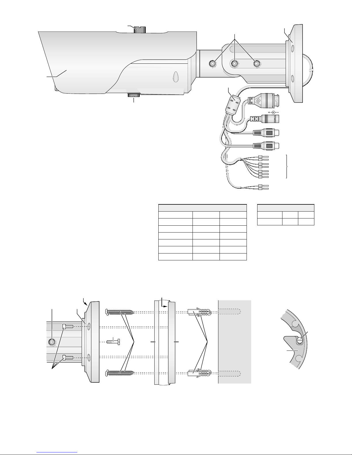
RS 485 (12)
RS 485 + braun brown
RS 485 − weiß white
Alarm (11)
OUT COM 1 orange orange
OUT 1 gelb yellow
OUT COM 2 weiß /schwarz white/ black
OUT 2 weiß /blau white/ blue
IN COM grau grey
IN 1 violett purple
IN 2 blau blue
③
Page 3

ELECTRONICS FOR SPECIALISTS ELECTRONICS FOR SPECIALISTS ELECTRONICS FOR SPECIALISTS ELECTRONICS FOR SPECIALISTS
3
Deutsch
1 Verwendungsmöglichkeiten. . . . . . . . . . . 4
1.1 Wärmestrahlung . . . . . . . . . . . . . . . . . . 4
2 Wichtige Hinweise . . . . . . . . . . . . . . . . 4
3 Montage . . . . . . . . . . . . . . . . . . . . . 5
4 Kamera anschließen . . . . . . . . . . . . . . . 5
5 Fokus einstellen. . . . . . . . . . . . . . . . . . 5
6 Kamera in ein Netzwerk einbinden . . . . . . . 6
7 Kamera über einen Computer aufrufen. . . . . 6
7.1 Sensor-Menü . . . . . . . . . . . . . . . . . . . . 8
7.2 Configuration-Menü . . . . . . . . . . . . . . . . 9
7.2.1 Temperature Parameters . . . . . . . . . . . . 9
7.2.2 Temperature Area … . . . . . . . . . . . . . .10
8 Rücksetzen der Kamera . . . . . . . . . . . . .10
9 Technische Daten . . . . . . . . . . . . . . . . .11
English
1 Applications. . . . . . . . . . . . . . . . . . . .12
1.1 Thermal radiation. . . . . . . . . . . . . . . . . .12
2 Important Notes . . . . . . . . . . . . . . . . .12
3 Installation . . . . . . . . . . . . . . . . . . . .13
4 Connecting the Camera . . . . . . . . . . . . .13
5 Adjusting the Focus . . . . . . . . . . . . . . .13
6 Connecting the Camera to a Network . . . . .14
7 Calling up the Camera via a Computer . . . . .14
7.1 Sensor menu . . . . . . . . . . . . . . . . . . . .16
7.2 Configuration menu . . . . . . . . . . . . . . . .17
7.2.1 Temperature Parameters . . . . . . . . . . . .17
7.2.2 Temperature Area … . . . . . . . . . . . . . .18
8 Resetting the Camera . . . . . . . . . . . . . .18
9 Specifications . . . . . . . . . . . . . . . . . . .19
Page 4

4
Deutsch
Netzwerk-Wärmebildkamera
Diese Anleitung richtet sich an Installateure von Video überwachungsanlagen. Bitte
lesen Sie die Anleitung vor der Installation
gründlich durch und heben Sie sie für ein
späteres Nachlesen auf.
1 Verwendungsmöglichkeiten
Die Wärmebildkamera INC-1500THERM
ist speziell für den Einsatz in Video-Überwachungsanlagen auf der Basis von Computer-Netzwerken konzipiert. Sie kommt
völlig ohne Licht aus und liefert auch bei
schlechten Sichtverhältnissen, wie z. B.
bei Nebel, kontrastreiche Bilder. Zudem
hat sie bei der Erkennung z. B. von Lebewesen oder Fahrzeugen eine hohe Reichweite. Damit bildet sie in einer Videoüberwachungsanlage die ideale Ergänzung
zu optischen Videokameras. Durch ihr wetterfestes Ge häuse (Schutzart IP 66) ist sie
auch für die Außeninstallation geeignet.
Sie ist mit einem Infrarotsensor und einem
15-mm-Objektiv ausgestattet und bietet
u. a. Bildspiegelung, Maskierung von Bildbereichen, Bewegungs erkennung und Temperaturalarm in wählbaren Bildbereichen.
Die Kamera verfügt über einen eingebauten Webserver mit 2-fach-Videostreaming. Für die korrekte Einrichtung
sind unbedingt Netzwerktechnik-Kenntnisse er forderlich.
Die Kamera kann in Verbindung mit
einem Netzwerk-Videorekorder (z. B.
INR-…*) genutzt werden oder eigenständig über einen Webbrowser. Sie verfügt
über einen Audio eingang und einen Audioausgang, sodass eine gegenseitige Kommunikation über einen Computer möglich
ist. Zwei Schaltausgänge erlauben das
Schalten von Geräten, z. B. durch die integrierte Bewegungserkennung oder Temperaturänderungen ausgelöst. Zusätzlich verfügt die Kamera über zwei Alarmeingänge,
über die z. B. eine Aufzeichnung oder eine
E-Mail-Benachrichtigung gestartet werden
kann. Ein Steckplatz für eine Speicherkarte erlaubt die Videoaufzeichnung in der
Kamera, nach Zeitplan oder durch einen
aufgetretenen Alarm ausgelöst.
Über die RS-485-Anschlüsse lässt sich
ein Schwenk-Neige-Kopf ansteuern, der
dann über den PTZ-Dialog am Computer
oder über einen Videorekorder gesteuert
werden kann.
* Tipp: Ist das Kameramodell in der Liste des ver-
wendeten Rekorders nicht vorhanden, das
ONVIF-Protokoll wählen.
1.1 Wärmestrahlung
Von jedem Körper geht eine elektromagnetische Strahlung aus, die von der Temperatur und Oberflächenbeschaffenheit
des Körpers abhängt. Dadurch ist für die
thermische Erkennung eines Körpers keine
zusätzliche Strahlungsquelle erforderlich,
wie z. B. bei der optischen Erkennung, die
eine Lichtquelle benötigt. Die Strahlung
liegt bei Temperaturen bis etwa 600 °C
im Infra rotbereich, d. h. außerhalb des für
Menschen sichtbaren Bereichs. Der Sensor
der INC-1500THERM, ein Mikrobolometer
vom Typ IRFPA (Infrarot Focal Plane Array),
kann Infrarotstrahlung im Bereich IR-C mit
einer Wellenlänge von 8 bis 14 µm erkennen. Die empfangene Strahlung wird von
der Kamera als Wärmebild dargestellt. Zur
Unterscheidung der Temperaturbereiche innerhalb des Wärmebilds stehen verschiedenen Falschfarbendarstellungen zur Auswahl
(☞Kapitel 7.1).
Eine ideale thermische Strahlungsquelle
wird „Schwarzer Körper“ genannt. Dieser absorbiert alle auftreffende Strahlung
vollständig und die von ihm ausgehende
Strahlung hängt nur von seiner Temperatur
ab. Bei einem realen Körper dagegen wird
zusätzlich ein Teil der Strahlung aus der
Umgebung reflektiert oder hindurchgelassen, sodass die vom Körper abgegebene
Strahlung nicht allein von seiner Temperatur abhängt.
Wieviel Strahlung ein realer Körper im
Vergleich zum Schwarzen Körper aussendet, wird mit dem Emissionsgrad ε angegeben. Der Emissionsgrad wird für den
Schwarzen Körper mit ε =1 angenommen
und ist bei realen Körpern kleiner als 1. Er
ist von der Oberflächenbeschaffenheit (Material, Rauheit) des Körpers sowie von der
Temperatur und Wellenlänge abhängig. Für
die meisten Materialien kann der Emissionsgrad für den Temperaturbereich 0 – 100 °C
grob in die folgenden beiden Gruppen eingeteilt werden: ε= 0,02 – 0,20 für metallische Oberflächen und ε=0,90 – 0,98 für
nichtmetallische Oberflächen.
Eine genaue Messung der Temperatur über die Strahlung eines Körpers kann
demnach nur erfolgen, wenn die Eigenschaften seiner Oberfläche bekannt sind.
Aus einschlägigen Tabellen lässt sich der
zutreffende Emissionsgrad ablesen. Dieser
kann im Einstellmenü „Configuration“ der
INC-1500THERM auf der Seite „Thermal
Temperature Area“ als „Target Emission
Rate“ eingeben werden (☞Kapitel 7.2.2).
Um bei der Messung die am Körper reflektierte Strahlung zu berücksichtigen, kann
auf der Seite „Thermal Temperature Pa-
rameters“ die Umgebungstemperatur als
„Ambient Temperature“ eingegeben werden (☞Kapitel 7.2.1).
Für den Überwachungseinsatz ist der
Emissionsgrad eines beobachteten Objekts
in der Regel nicht bekannt und es wird auch
kein genauer Temperaturmesswert benötigt. Das Hauptinteresse liegt vielmehr im
Erhalt eines kontrastreichen Wärmebilds
als Ergänzung zur Videoüberwachung.
Dennoch ist es für die Beurteilung eines
Wärme bilds hilfreich, eine Vorstellung von
den Eigenschaften der thermischen Strahlung zu haben und sich darüber im Klaren
zu sein, dass eine angezeigte Temperatur
nicht exakt die Temperatur eines Objekts
sein muss, sondern von der Beschaffenheit
der Oberfläche des Objekts und von Reflexionen aus der Umgebung mitbestimmt
wird.
2 Wichtige Hinweise
Die Kamera entspricht allen relevanten
Richtlinien der EU und ist deshalb mit
gekennzeichnet.
•
Schützen Sie die Kamera vor extremen
Temperaturen (zulässige Einsatztemperatur −10 °C bis +55 °C).
•
Richten Sie die Kamera niemals auf starke
Strahlungsquellen, wie z. B. Sonne, Laser
oder Lichtbogenschweißen. Die Genauigkeit des Sensors kann beeinträchtigt
werden.
•
Schützen Sie die Kamera auch beim
Transport vor starken Erschütterungen.
•
Verwenden Sie für die Reinigung des
Kameragehäuses keine aggressiven Reinigungsmittel oder Chemikalien. Zum
Säubern des Objektivs kann ein weiches
Tuch verwendet werden, das mit Isopropylalkohol oder einem Reinigungsmittel
für optische Linsen angefeuchtet ist.
•
Wird die Kamera zweckentfremdet, nicht
richtig angeschlossen, falsch bedient
oder nicht fachgerecht repariert, kann
keine Haftung für daraus resultierende
Sach- oder Personenschäden und keine
Garantie für die Kamera übernommen
werden. Ebenso kann keine Haftung für
durch Fehlbedienung oder durch einen
Defekt entstandene Datenverluste und
deren Folgeschäden übernommen werden.
Soll die Kamera endgültig aus dem
Betrieb genommen werden, übergeben Sie sie zur umweltgerechten
Entsorgung einem ört lichen Recyclingbetrieb.
Page 5
5
Deutsch
3 Montage
1) Um die optimale Montagestelle festzustellen, sollte ein Probebetrieb erfolgen.
Dazu die Kamera vorläufig in Betrieb
nehmen (☞folgende Kapitel).
2) An der Montagestelle (z. B. Wand oder
Decke) vier Löcher für die Befestigung
der Montageplatte und ggf. ein Loch für
das An schluss kabel bohren (das Kabel
kann alternativ durch die Aussparung
seitlich am Sockel herausgeführt werden). Eine Bohrschablone liegt bei. Bei
Bedarf die beiliegenden Dübel (18) verwenden.
3) Mit den vier langen Kreuzschlitzschrauben (15) die Montageplatte (17) an
der Montagestelle befestigen. Bei der
Wandmontage darauf achten, dass die
Seite mit der Beschriftung „TOP“ nach
oben zeigt (☞ Abb. 2).
4)
Die Gummidichtung (16) mit etwas Dehnung über den Rand der Montageplatte
(17) stülpen.
5)
Die Schlitzschraube (14) bis zum Anschlag in das Gewinde am Kamerahaltersockel (5) drehen.
6)
Den Sockel (5) so auf die Montageplatte
(17) setzen, dass der Schraubenkopf in
die Öffnung in der Montageplatte fasst
und sich nach einer Linksdrehung darin
verriegelt (☞ Abb. 3).
7)
Mit den vier Inbusschrauben (13) den
Sockel (5) an der Montageplatte (17)
festschrauben.
8)
Zum Ausrichten der Kamera die drei
Feststellschrauben (4) lösen, die Kamera
ausrichten und die Schrauben wieder
festdrehen.
Vorsicht: Vermeiden Sie die direkte Ausrichtung
der Kamera auf starke Lichtquellen
(z. B. Sonne). Dies könnte die Lebensdauer des Bildsensors verkürzen.
9)
Um das Objektiv vor direkter Sonneneinstrahlung zu schützen, das Sonnendach
(1) auf der Kamera positionieren und mit
der Feststellschraube (2) fixieren.
4 Kamera anschließen
Die Anschlüsse (7 – 12) und der Kabelverteiler (6) sind nicht wetterfest. Sie müssen
entsprechend geschützt werden.
1)
Die Kamera über den RJ45-Anschluss (7)
mit einem einzelnen Computer, einem
lokalen Computernetzwerk oder, z. B.
über einen Router, mit größeren Computernetzwerken (Internet) verbinden.
Auf der Kameraunterseite ist durch das
Fenster im Deckel des Fachs eine gelbe
LED (21 in Abb. 4) sichtbar. Diese blinkt
beim Bestehen einer Netzwerkverbindung.
2) Für die Tonübertragung über das Netzwerk kann an die Cinch-Kupplung
„AudioInput“ (9) eine Tonquelle mit
Line-Pegel (z. B. Mikrofon mit Vorverstärker) angeschlossen werden.
3)
Für die Tonwiedergabe an die CinchKupplung „Audio Output“ (10)
einen Kopfhörerverstärker oder eine
Lautsprecher anlage anschließen.
4)
Zur Auswertung eines Alarmgebers
die Anschlüsse (11) IN 1 oder IN 2 und
IN COM über einen Schließkontakt oder
Öffner (in den Kameraeinstellungen
wählbar) verbinden.
5)
Zum Schalten eines Geräts, z. B. über
ein Relais, dieses an den Schaltausgang
OUT 1 und OUT COM 1 oder OUT 2
und OUT COM 2 der Kamera anschließen (11). Die Schalt charakteristik (Öffner/ Schließer, Puls) ist in den Kameraeinstellungen wählbar. Der Ausgang ist
max. mit ⎓12 V/ 300 mA belastbar.
6)
Zur PTZ-Steuerung eines SchwenkNeige-Kopfes über eine RS-485-Schnittstelle diesen mit den Anschlüssen
RS 485+ und RS 485− (12) verbinden.
7)
Soll die Kamera eigenständig Video-Aufzeichnungen durchführen, nach Lösen
der Schraube (3) den Deckel des Fachs
öffnen und eine Speicherkarte vom Typ
„SD[HC]“ (max. 128 GB) einsetzen.
Den Schreibschutz der Karte (seitlicher
Schieber) deaktivieren. Die Karte mit den
Kontakten zur Kamera vorderseite zeigend in den Schlitz (19) schieben, bis
sie einrastet. Die rote LED (20) leuchtet
bei eingesetzter Karte. Ein Adapter für
Karten vom Typ „micro SD[HC]“ liegt bei.
Zum Entnehmen der Karte eine laufende Aufnahme unbedingt zuvor be-
enden! Die Karte dann etwas hineindrücken, sodass sie ausrastet.
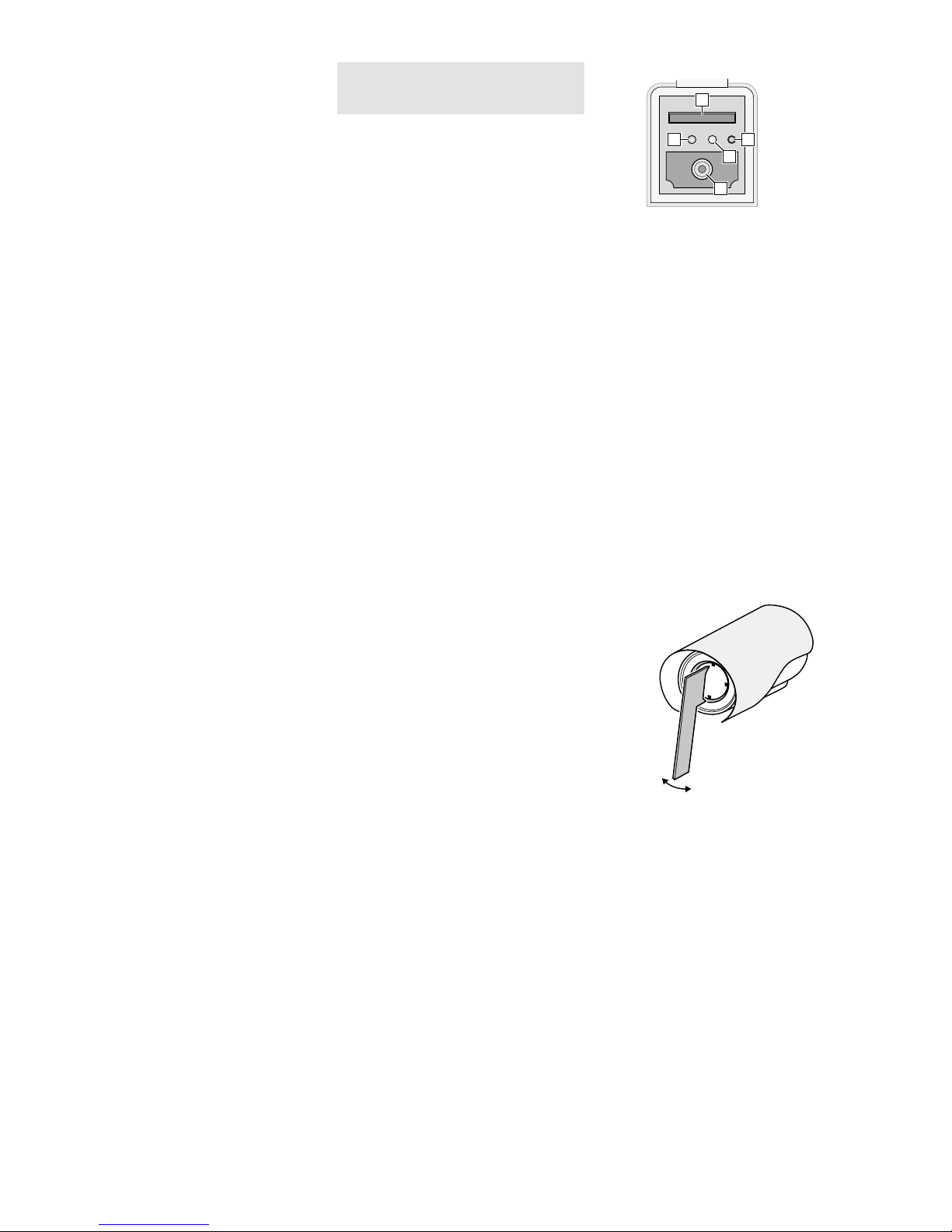
④
22
20
21
23
19
Den Deckel wieder dicht verschließen.
8)
An die Kupplung (8) ein stabilisiertes
12-V-Netz gerät mit einer Dauerbelastbarkeit von 420 mA (z. B. PSS-1210DC
oder PS-120WP) über einen Hohlstecker
⌀ 5,5 / 2,1 mm (außen /innen) anschließen. Dabei die Polung beachten:
Mittelkontakt = +.
Alternativ lässt sich die Kamera auch
über das Netzwerkkabel versorgen
(Power over Ethernet IEEE 802.3af).
5 Fokus einstellen
Für eine genaue Temperaturmessung ist
eine korrekte Fokussierung erforderlich.
Zur Fokuseinstellung den beiliegenden
Schlüssel in zwei gegenüberliegende Vertiefungen neben dem Objektiv stecken und
das Objektiv drehen, sodass ein möglichst
scharfes Bild gezeigt wird (☞Abbildung 5).
Vorsicht: Behutsam mit dem Schlüssel umgehen.
Ein Abrutschen könnte das Objektiv beschädigen.
⑤
Als Hilfe für die Einstellungen steht im
Fach an der Kameraunterseite ein analoges Video signal zur Verfügung, wenn die
Signalausgabe in den Kamera einstellungen
„Device CVBS“ aktiviert wurde (☞ Kapitel 7). Den Deckel des Fachs durch Lösen
der Schraube (3) öffnen und die CinchBuchse (23 in Abb.4) mit dem Eingang
eines Monitors verbinden.
Nach der Durchführung der Einstellungen
den Deckel wieder dicht verschließen.
Page 6
6
Deutsch
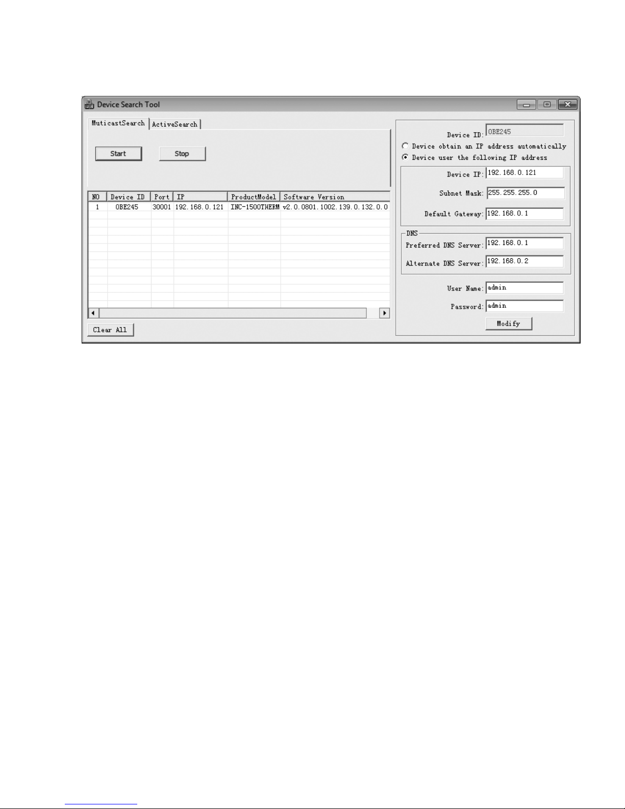
6 Kamera in ein Netzwerk einbinden
Damit die Kamera zum Konfigurieren über einen Computer direkt
angesprochen werden kann, ist ihre IP-Adresse vom Werk aus auf
192.168.0.121 voreingestellt.
Ist die aktuelle Adresse der Kamera nicht bekannt, zum Finden
der Kamera im Netzwerk das auf der beiliegenden CD enthaltene
Programm „IPSearch.exe“ starten.
1)
Um die Suche zu starten, auf der Registerkarte „Multicast
Search“ die Schaltfläche „Start“ anklicken. Die im Netzwerk
gefundenen Kameras werden in der Liste auf der linken Seite
angezeigt (☞Abb.6).
2) Zum Beenden der Suche auf die Schaltfläche „Stop“ klicken.
3) Die Kamera in der Liste auswählen. Auf der rechten Seite werden jetzt die aktuellen Einstellungen dieser Kamera gezeigt.
4) Die Einstellungen nach Bedarf ändern:
IP-Adresse, Teilnetzmaske und Gateway-Adresse können statisch festgelegt werden (Option „Device uses the following IP
address“ wählen). Dabei muss für jede Kamera eine eindeutige
IP-Adresse eingegeben werden. Existiert in dem Netzwerk ein
DHCP-Server (z. B. im Router oder Netzwerk-Videorekorder),
kann dieser Einstellungen für die Kamera automatisch vornehmen (Option „Device obtains an IP address automatically“
wählen); die automatisch vergebenen Werte sind dann grau
hinterlegt und können nicht geändert werden.
5) Auf die Schaltfläche „Modify“ klicken. Bei erfolgreicher Übertragung der Änderungen wird die Meldung „Modify success!“
angezeigt.
6) Vor einer erneuten Suche kann die Liste über die Schaltfläche
„Clear All“ gelöscht werden.
7 Kamera über einen Computer aufrufen
Die Bedienoberfläche der Kamera kann durch die Eingabe ihrer
IP-Adresse in der Adresszeile des Programms Windows Internet
Explorer (IE, Version 6 oder höher) aufgerufen werden. Dazu müssen die IP-Adressen vom Computer und der Kamera demselben
Teilnetz angehören. Es sind max. 6 gleichzeitige Zu griffe auf die
Kamera möglich.
Beim Aufruf der Kamera erscheint zunächst das Anmeldefenster. Hier die Sprache für die Benutzeroberfläche wählen; die
folgende Beschreibung bezieht sich auf die Einstellung „ English“.
Anschließend den Benutzernamen und das Passwort eingeben (Vorgabe für beide Eingaben: admin). In den Kameraeinstellungen können später eigene Anmeldedaten festgelegt werden.
Wichtig: Gegen einen unbefugten Zu gang sollte zumindest das Passwort ge-
ändert werden.
Eine einfache Darstellung des Kamerabilds ist mit der auf vielen
Computern vorhandenen Flash-Player-Erweiterung von Adobe
möglich (auch auf beiliegender CD). Für eine schnellere Bildübertragung sowie die Nutzbarkeit aller Funktionen ist jedoch die Installation der ActiveX-Erweiterungen erforderlich. Diese werden
beim erstmaligen Klicken auf die Flash /Ac tiveX-Umschaltzeile g
(☞Abb. 7) aus der Kamera geladen. Wenn nötig, müssen dafür
die Sicherheitseinstellungen des IE so gelockert werden, dass dieser
Vorgang zugelassen wird. Die Installationsdatei „webPlugins.exe“
auf dem Computer speichern, den IE schließen und die Datei
ausführen.
Windows ist ein registriertes Warenzeichen der Microsoft Corporation in den USA und anderen
Ländern.
⑥
Page 7

7
Deutsch
f
e
a
g
h
b c
d
Ist die Verbindung zur Kamera aufgebaut, wird die in Abb. 7
gezeigte Ansicht mit dem aktuellen Kamerabild angezeigt, mit
folgenden Bedienmöglichkeiten:
a
Ansicht „Live Video“ mit Anzeige des Kamerabilds
b
Ansicht „Playback“ zum Abspielen der Aufnahmen aus der
Kamera
c
Ansicht „Configuration“ zum Ändern der Kameraeinstellungen
d
Schaltfläche zum Ändern des Passworts
e
Schaltfläche zum Abmelden
f
Kamerabild mit Informationen zum aktuell übertragenen Stream
g
Zum Umschalten zwischen Flash-Player- und ActiveX-Nutzung
für die Darstellung des Live-Bildes auf diese Zeile klicken.
h
Funktionsleiste mit folgenden Funktionen
: Aufrufen der PTZ-Steuerung
/ : Beenden / Starten der Bildübertragung
„Stream“: Auswahl eines Streams (zur Änderung die Übertra-
gung eines laufenden Streams mit beenden)
: Tonübertragung von der Kamera ein-/ausschalten
[Audio Input (9)]
: Tonübertragung zu der Kamera ein-/ausschalten
[Audio Output (10)]
: spezifische Kameraeinstellungen
(z. B. Farbschema, Spiegelung)
: Schnappschuss-Funktion zum Speichern einer Moment-
aufnahme als Bild
Das Klicken mit rechter Maustaste auf das Kamerabild zeigt folgendes Menü:
Menüpunkt Funktion
Full Screen (Exit Full Screen)
Vollbildansicht (beenden)
alternativ: Doppelklick auf das Bild
Sensor
wie
Zoom In / Out
Hinein-/Herauszoomen
alternativ: mit Mausrad zoomen oder über
dem gewünschten Bildausschnitt einen Rahmen aufziehen
Restore Panorama gesamtes Bild zeigen (nach Zoom In)
Turn on /off the mouse to
measure the temperature
Temperaturmessung an der Position des
Mauszeigers ein/aus
⑦
Page 8

8
Deutsch
Zum Ändern der Einstellungen für die Kamera, über den Reiter
c
auf die Ansicht „Configuration“ umschalten (☞Abb. 8). Am
linken Rand (i) die gewünschte Rubrik für die Einstellungen auswählen. Durch Klicken auf ⊞ lassen sich weitere Unterrubriken
anzeigen. So lässt sich z. B. unter „Device Date and Time“ die
aktuelle Zeit für die Kamera einstellen.
Nach dem Ändern einer Einstellung zum Speichern der Änderung auf den grünen Haken ✔ oder die Schaltfläche „Apply“
klicken. Zum Laden der aktuellen Einstellungen aus der Kamera
auf die Schaltfläche „Refresh“ klicken.
Die Einstellmöglichen der INC-1500THERM entsprechen größtenteils denen von optischen Netzwerkkameras. Im Folgenden
werden deshalb nur die speziellen Einstellungen für diese Kamera
beschrieben.
7.1 Sensor-Menü
Nach dem Klicken auf das Symbol oder den Menüpunkt „Sensor“ beim Klicken der rechten Maustaste auf das Bild erscheint
folgende Einblendung:
⑨
Sensor-Menü
Ansicht Einstellung Funktion
Time Zone
ON Zeitbetrieb für diese Einstellungen aktiv: yes /no
Start Time Startzeitpunkt
End Time Endzeitpunkt
Image Setting
Polarity/ LUT
Farbschemen für die Falschfarbendarstellung des Wärmebilds:
White Hot, Black Hot, Rainbow, Ironbow, HSV, Autumn, Bone, Cool, Copper, Fire Hot, Pink, Spring, Winter,
Jet, Flame, Rosebengal
Mirror Bildspiegelung: aus, horizontal, vertikal, horizontal und vertikal
Dynamic DVE Grad der Bildschärfung für DVE Mode 1 oder Kontraständerung für DVE Mode 2
DVE Mode Default, Mode 1, Mode 2
FFC Mode
FFC Mode
Korrektur ungleichmäßiger Sensorpixelwerte (Flat Field Correction):
Auto = automatische Korrektur nach Zeit (FFC interval) oder Temperaturänderung
Manual (Debug) = zum manuellen Abgleich (Nicht im Normalbetrieb durchführen!)
External (Debug) = interne Korrektur deaktiviert
FFC interval (min) Korrekturabstand in Minuten
Flat Field Correction Manuellen Abgleich auslösen
DNR
3DNR 3DNR-Rauschunterdrückung on /off
2DNR 2DNR-Rauschunterdrückung on /off
Lens Control bei diesem Kameramodell ohne Funktion
Adjust the Screen
Mode selection
Wahl der Anwendungsumgebung als Voreinstellung für ein kontrastreiches Bild:
Outdoor, Indoor, Sky/Earth, Sea /Sky, Linear, Common, Custom
Contrast Kontrast
Brightness Helligkeit
i
c
⑧
Page 9

9
Deutsch
Im Listenfeld unten links kann der Modus gewählt werden (Abb.9).
Zum Ändern der Einstellungen den „Debug Mode“ wählen. Durch
den Wechsel zum „Standard Mode“ kann ein Vergleich mit den
vorherigen Einstellungen durchgeführt werden. Beim Wechsel zum
„Standard Mode“ das Speichern der Änderungen für den „Debug
Mode“ bestätigen. Beim Schließen des Sensor-Menüfensters erscheint die Frage, ob vom „Debug Mode“ wieder in den „Standard
Mode“ gewechselt werden soll.
Über das zweite Listenfeld können im „Debug Mode“ zuvor
mit „Save“ gespeicherte Einstellungen (Scheme 1 – 4) abgerufen
werden. Für die gespeicherten Einstellungen kann jeweils ein Gültigkeitszeitraum festgelegt werden (Ansicht „Time Zone“).
Mit „Reset“ lassen sich die vorgenommenen Änderungen
wieder auf die gespeicherten Werte zurücksetzen. Mit „Factory
Setting“ lassen sich die Werkseinstellungen für den „Standard
Mode“ wiederherstellen.
In der Tabelle auf Seite 8 sind die Einstellmöglichkeiten des Sensor-Menüs aufgeführt.
7.2 Configuration-Menü
Im Menü „Configuration“ gibt es unter der Rubrik „Thermal“
folgende zwei Ansichten für die speziellen Einstellungen dieser
Kamera.
7.2.1 Temperature Parameters
In dieser Ansicht können folgende Einstellungen durchgeführt
werden:
Einstellung Funktion
Temperature Unit Temperaturmaßeinheit: Celsius, Fahrenheit
Ambient Type
Einsatzumgebung:
Inside = Innenbereich
Outside = Außenbereich
Ambient Temperature Umgebungstemperatur
Cavity Temperature
Gehäusetemperatur des Sensors
(nur Anzeige)
Correction Coefficient Korrekturwert (Offset)
Area Temperature
Display Mode
Art und Position der Temperaturanzeige:
Hidden area and temperature display = keine An-
zeige von Temperatur, Bildbereichen (☞ Kap. 7.2.2)
und Positionen der Temperaturmaxima
Low Left = Temperaturanzeige unten links
Low Right = Temperaturanzeige unten rechts
Upper Right = Temperaturanzeige oben rechts
Display Area Only = nur Anzeige von Bildbereichen
und Positionen der Temperaturmaxima
⑩
Page 10

10
Deutsch
7.2.2 Temperature Area …
In dieser Ansicht können Bildbereiche festgelegt werden, die in
Bezug auf die Temperaturmessung besonders überwacht werden
sollen. Zum einen lassen sich die Temperaturen in diesen Bereichen
durch die Eingabe des Emissionsgrads und der Entfernung eines
darin befindlichen Messobjekts genauer bestimmen. Zum anderen können für die Bereiche Temperaturwerte festgelegt werden,
bei deren Überschreitung z. B. eine Warnung angezeigt oder ein
Alarm ausgelöst wird.
1)
Bei „Area ID“ den einzustellenden Bereich „Area 1 – 7“ wählen
oder „Full Image“, wenn sich die Einstellungen auf das gesamte
Bild beziehen sollen. Bei „Area Name“ kann ein Name für den
gewählten Bereich eingegeben werden.
2)
Zur Festlegung eines der Bereiche „Area 1 – 7“ mit der Maus ein
Rechteck über dem gewünschten Bildausschnitt aufziehen. Das
Rechteck blinkt zunächst, wird aber nach der Übernahme mit
„Apply“ mit deutlichen Ecken und seiner Nummer angezeigt.
3) Bei „Target Emission Rate“ den Emissionsgrad ε und bei „Target Distance“ die Entfernung des in dem gewählten Bereich
befindlichen Messobjekts eingeben.
4)
Soll nicht nur die maximale Temperatur in einem Bereich gemessen werden, sondern auch bei Überschreitung einer bestimmten
Temperatur eine Warnung angezeigt oder ein Alarm ausgelöst
werden, bei „Alarm Type“ die Art der Auslösung wählen.
Threshold Alarm: Warnung und Alarm werden ausgelöst, sobald
die vorgegebene Temperatur überschritten wird.
Temperature Difference Alarm: Warnung und Alarm werden
ausgelöst, sobald die Temperatur um den vorgegebenen Betrag
abweicht.
5)
In die Felder „Warning Value“ und „Alarm Value“ den Schwellwert bzw. die Differenz für das Auslösen einer Warnung und
für das Auslösen eines Alarms eingeben.
Alle Warnungen und Alarmereignisse werden protokolliert und
können über „Configuration Device Log Alarm Log“ abgeru-
fen werden. Beim Quittieren des Alarms durch Klicken auf die
im Alarmfall eingeblendete Schaltfläche wird das Protokoll
automatisch angezeigt.
6) Bei „Output Channel“ kann festgelegt werden, ob ein Alarm
in diesem Bereich zum Auslösen eines Alarmausgangs OUT 1/
OUT 2 (11) führen soll (Einstellmöglichkeiten der Alarmausgänge
☞
„Configuration Alarm I /O Alarm“).
7)
Im Zeitplan unter dem Bild den Gültigkeitszeitraum für den Temperaturalarm des Bereichs festlegen. Vertikal sind die Wochentage Sonntag bis Samstag, Horizontal die Stunden angezeigt. Ein
blau gefülltes Kästchen bedeutet, dass die Alarmerkennung in
dieser halben Stunde aktiv ist. Durch Klicken auf das Kästchen
kann der Zustand geändert werden. Mit kann ein ganzer Tag
oder der komplette Zeitplan umgeschaltet werden.
8)
Mit „Enable“ lässt sich die Alarmauslösung und Protokollierung
für den Bereich generell ein- und ausschalten.
9) Die durchgeführten Änderungen mit „Apply“ in der Kamera
speichern.
Bei Bedarf weitere Bildbereiche für die Überwachung konfigurieren.
8 Rücksetzen der Kamera
Die Kamera kann auf ihre Werkseinstellungen zurückgesetzt werden. Dabei gehen alle vom Anwender durchgeführten Änderungen
der Kameraeinstellungen verloren.
1) Die Schraube (3) des Deckels lösen und das Fach öffnen.
2)
Den Reset-Taster (22) länger als 5 Sekunden drücken (☞ Abb.4
in Kapitel 4). Der Rücksetzprozess startet nach dem Loslassen
der Taste verzögert und kann einige Minuten dauern.
3) Den Deckel wieder dicht verschließen.
Die Kamera ist jetzt wieder auf die statische IP-Adresse
192.168.0.121 eingestellt, der Benutzername und das Kennwort
für die Anmeldung lauten: admin
⑪
Page 11

11
Deutsch
9 Technische Daten
Detektortyp: . . . . . . . . . . langlebiges, ungekühltes IRFPA-
Mikrobolometer
Objektiv: . . . . . . . . . . . . . 15 mm / 1 : 1,0
Blickwinkel: . . . . . . . . . . . 24° × 18°
Auflösung: . . . . . . . . . . . max. 30 Bilder / s bei 400 × 300 Bild-
punkten
Empfindlichkeit: . . . . . . . 50 mK
Spektralbereich: . . . . . . . 8 –14 µm
Reaktionszeit: . . . . . . . . . 30 ms
Erkennungsreichweite
Person (1,8 × 0,5 m²): . . 225 m
Fahrzeug (2,3 × 2,3 m²): 500 m
Temperaturerfassungsreichweite
Feuer (0,8 × 0,8 m²): . . . 300 m
Protokolle: . . . . . . . . . . . IPv4, IPv6, HTTPS, RTSP, DDNS, SMTP,
PELCO D/P ONVIF2.4 u. a.
Kompressionsverfahren: . MPEG-4 H.264, H.265, MJPEG
Audiokompression: . . . . . G.711, RAW PCM
Videostreaming: . . . . . . . CBR / VBR 100 – 6 000 kbit /s
Netzwerk: . . . . . . . . . . . . Ethernet 10 / 100 Mbit / s
Einsatztemperatur: . . . . . −10 °C bis +55 °C
Schutzart: . . . . . . . . . . . . IP 66
Stromversorgung: . . . . . . ⎓12 V/420 mA oder PoE IEEE 802.3af
Abmessungen: . . . . . . . . ⌀ 110 mm × 388 mm
Gewicht: . . . . . . . . . . . . . 1,9 kg
Änderungen vorbehalten.
Diese Bedienungsanleitung ist urheberrechtlich für MONACOR ® INTERNATIONAL GmbH & Co. KG geschützt.
Eine Reproduktion für eigene kommerzielle Zwecke – auch auszugsweise – ist untersagt.
Page 12

12
English
Thermal Imaging Network
Camera
These instructions are intended for installers
of video surveillance systems. Please read
the instructions carefully prior to installation and keep them for later reference.
1 Applications
The thermal imaging camera INC1500THERM is specially designed for video
surveillance systems based on computer
networks. It does not need any light at all;
even in conditions of poor visibility (e. g.
fog), it offers high-contrast images. Furthermore, it has a long detection range,
e. g. for people, animals or vehicles. Thus,
this thermal imaging camera will ideally
complement optical video cameras in
video surveillance systems. Its housing is
weather proof (IP 66); therefore, the camera
is also suited for outdoor applications. It
is equipped with an infrared sensor and a
15 mm lens. The camera features include
mirror image, masking of image areas, motion detection and thermal alarm in image
areas to be selected.
The camera is provided with an integrated web server with 2-way video streaming. For correct configuration, knowledge
in network technology is indispensable.
The camera can be operated in combination with a network video recorder (e. g.
INR-…*) or operated independently via a
web browser. It is equipped with an audio
input and an audio output so that mutual
communication via a computer will be possible. Two switching outputs are provided
for switching units, e. g. triggered by integrated motion detection or temperature
changes. The camera also offers two alarm
inputs. These inputs can be used, for example, to start recordings or e-mail messages.
A slot for memory cards allows you to make
video recordings in the camera according
to schedule or triggered by alarm.
The RS-485 connectors can be used to
activate a pan / tilt head. This pan / tilt head
will be controlled via PTZ dialog on the
computer or by means of a video recorder.
*Hint: If this camera model does not appear in the
list of the recorder used, select the ONVIF
protocol.
1.1 Thermal radiation
All objects emit electromagnetic radiation depending on their temperature and
surface. Unlike video detection which requires a light source, thermal detection of
an object does not require any additional
radiation source. For temperatures up to
approximately 600 °C, the radiation is in
the infrared range, i. e. outside the range
visible to the human eye. The sensor of INC1500THERM, a microbolometer of the type
IRFPA (Infrared Focal Plane Array), is able
to detect infrared radiation in the range
IR-C with a wavelength of 8 to 14 µm. The
camera will show a thermal image of the
radiation detected. Various colour schemes
for false colour rendering are available to
distinguish the temperature areas within
the thermal image (☞chapter 7.1).
A “black body” is an ideal thermal radiation source. It will completely absorb all
incident radiation; the radiation emitted is
only determined by its temperature. A real
object, on the other hand, will also reflect
or transmit a fraction of the radiation from
the environment so that the radiation emitted by the object does not solely depend
on its temperature.
The emissivity ε is the radiation emitted by a real object compared to a black
body. For black bodies, the emissivity is
assumed to be ε = 1; for real objects, it is
less than 1. It depends on the surface properties (material, roughness) of the object
and also on the temperature and wavelength. For most materials, the emissivity
for the temperature range of 0 –100 °C
can be roughly divided into the two following groups: ε=0.02 – 0.20 for metallic
surfaces; ε= 0.90 – 0.98 for non-metallic
surfaces.
An accurate measurement of the temperature by means of the radiation of an
object will therefore only be possible if
you know its surface properties. The corresponding emissivity can be found in the
relevant tables. In the setup menu “Configuration” of INC-1500THERM, the emissivity
can be entered as “Target Emission Rate”
on the page “Thermal Temperature Area”
(☞chapter 7.2.2). To take into account the
radiation reflected from the object during
the measurement, enter the ambient temperature as “Ambient Temperature” on the
page “Thermal Temperature Parameters”
(☞chapter 7.2.1).
Usually, the emissivity of an observed
object is not known during surveillance, but
a precise temperature value is not required.
The focus is rather on getting a high-contrast thermal image to complement video
surveillance. To evaluate a thermal image,
however, it is still useful to have an idea of
thermal radiation and to be aware of the
fact that the temperature indicated is not
necessarily the precise temperature of the
object; this temperature is also determined
by the surface properties of the object and
by reflections from its environment.
2 Important Notes
The camera corresponds to all relevant directives of the EU and is therefore marked
with .
•
Protect the camera against extreme temperatures (admissible ambient temperature range: −10 °C to +55 °C).
•
Never direct the camera towards sources
of high radiation, e. g. sun, laser or arc
welding. This may affect the accuracy of
the sensor.
•
Protect the camera against strong vibrations, also during transport.
•
Never use aggressive detergents or
chemicals when cleaning the camera
housing. For cleaning the lens, use a soft
cloth moistened with isopropyl alcohol or
optical lens cleaners.
•
No guarantee claims for the camera
and no liability for any resulting personal damage or material damage will be
accepted if the camera is used for other
purposes than originally intended, if it
is not correctly connected or operated,
or if it is not repaired in an expert way.
Likewise, no liability will be accepted for
any data loss due to operating errors or a
defect or for any consequential damage
caused by this data loss.
If the camera is to be put out of operation definitively, take it to a local
recycling plant for a disposal which
is not harmful to the environment.
Page 13

13
English
3 Installation
1)
A test operation is recommended in
order to find the best mounting location.
For this purpose, operate the camera
temporarily (☞next chapters).
2) At the mounting location (e. g. wall or
ceiling), drill four holes for fixing the
mounting plate and, if necessary, drill a
hole for the connection cable (alternatively, guide the cable through the cable
inlet on the side of the camera base). A
drilling jig is provided. Use the dowels
(18) provided, if required.
3) Use the four long recessed head screws
(15) to attach the mounting plate (17) to
the mounting location. When installing
the camera on a wall, make sure that the
side marked “TOP” is facing upwards
(☞fig. 2).
4) Slightly stretch the rubber seal (16) and
put it over the edge of the mounting
plate (17).
5) Turn the slotted head screw (14) as far
as it will go into the thread at the base
(5) of the camera support.
6)
Place the base (5) onto the mounting
plate (17) so that the hole in the mounting plate is positioned over the screw
head. Turn the mounting plate counter-clockwise. The screw head will slide
into the notch and secure the mounting
plate (☞fig. 3).
7)
Use the four hexagon socket screws (13)
to fasten the base (5) to the mounting
plate (17).
8)
To align the camera, release the three
locking screws (4), align the camera and
fasten the screws.
Caution: Do not aim the camera directly at the
sun or other bright light sources; this
may reduce the life of the image sensor.
9) To protect the lens from direct sunlight,
place the sunshield (1) on the camera
and fasten it with the locking screw (2).
4 Connecting the Camera
The connections (7 – 12) and the cable splitter (6) are not weatherproof; protect them
accordingly.
1) Connect the camera via the RJ45 connector (7) to an individual computer,
a local computer network or, e. g. via
a router, to larger computer networks
(Internet). On the lower side of the camera, a yellow LED (21 in fig. 4) is visible
through the window in the cover of the
compartment. This LED starts flashing
when the camera has been connected
to the network.
2) For audio transmission via the network,
connect an audio source with line level
(e. g. microphone with preamplifier) to
the RCA connector “Audio Input” (9).
3)
For audio reproduction, connect a headphone amplifier or a sound system to the
RCA connector “Audio Output” (10).
4)
To evaluate an alarm device, connect
the pins (11) IN 1 or IN 2 and IN COM
via a normally open contact or normally closed contact (to be selected in the
camera settings).
5)
To switch a unit, for example via a
relay, connect the unit to the switching output OUT 1 and OUT COM 1 or
OUT 2 and OUT COM 2 of the camera
(11). Select the switching characteristic
(normally open contact/normally closed
contact, pulse) in the camera settings.
The maximum load of the output is
⎓
12V/300 mA.
6)
For PTZ control of a pan/tilt head via
an RS-485 interface, connect the pan/
tilt head to the connectors RS485+ and
RS485− (12).
7)
For independent video recordings of the
camera, release the screw (3), open the
cover of the compartment and insert
a memory card of the type “SD[HC]”
(128 GB max.).
Disable the write protection of the
memory card (lateral slider). Push the
card (contacts to the front of the camera) into the slot (19) until it engages.
The red LED (20) will light up when a
card is inserted. An adapter for cards
of the type “microSD[HC]” is provided.
Never remove the card while a recording is being made! To remove the
card, push the card into the slot until it
disengages.
④
22
20
21
23
19
Tightly close the cover again.
8) Connect a regulated 12 V power supply
unit with a permanent rating of 420 mA
(e. g. PSS-1210DC or PS-120WP) via a
DC power connector ⌀ 5.5 / 2.1 mm
(outside/inside) to the connector (8). Always observe the correct polarity: centre
contact = +
Alternatively, use the network cable
(Power over Ethernet IEEE 802.3af) to
supply the camera with power.
5 Adjusting the Focus
Accurate temperature measurement requires correct focus adjustment. To adjust
the focus, use the key provided: Insert the
key into two opposite recesses next to the
lens and turn the lens until the image is as
sharp as possible (☞figure 5).
Caution: Be careful when handling the key: If it slips,
it may damage the lens.
⑤
To make settings easier, an analog video
signal will be available in the compartment
on the lower side of the camera if the signal
output has been activated in the camera
settings “Device CVBS” (☞chapter 7).
Release the screw (3), open the cover of
the compartment and connect the RCA
jack (23 in fig. 4) to the input of a monitor.
After making the settings, tightly close the
cover again.
Page 14

14
English
6 Connecting the Camera to a Network
To be able to directly address the camera for configuration via a
computer, its IP address is factory-set to 192.168.0.121.
If you do not know the current address of the camera, start the
program “IPSearch.exe” from the CD provided to find the camera
in the network.
1)
To start the search, click the button “Start” of the tab “Multicast
Search”. The list on the left will show the cameras found in the
network (☞fig. 6).
2) To stop the search, click the button “Stop”.
3)
Select the camera from the list. The current settings of this
camera can be found on the right.
4) Change the settings as required:
IP address, subnet mask and gateway address can be defined
as static values (select the option “Device uses the following IP
address”). Enter a unique IP address for each camera. If a DHCP
server is available in the network (e. g. in the router or network
video recorder), this server will be able to automatically make
settings for the camera (select the option “Device obtains an
IP address automatically”). The values assigned automatically
are highlighted in grey and cannot be changed.
5)
Click the button “Modify”. After successful transmission of
the modifications, the message “Modify success!” will appear.
6) Before you start a new search, click the button “Clear All” to
delete the list.
7 Calling up the Camera via a Computer
To call up the user interface of the camera, enter its IP address
in the address bar of the program Windows Internet Explorer (IE,
version 6 or higher). The IP addresses of the computer and of the
camera must be in the same subnet. The number of simultaneous
accesses to the camera is limited to 6.
When the camera is called up, the log-in window will appear.
Select the language for the user interface. The description below
refers to English. Then enter the user name and the password
(default setting for both: admin). Individual log-in data can be
defined later in the camera settings.
Important: To prevent unauthorized access, change at least the password.
The Flash Player extension from Adobe provided on many computers (also available on the CD provided) will allow a basic display of
the camera image. Faster image transmission and availability of all
functions, however, requires installation of the ActiveX extensions.
These extensions will be loaded from the camera when the Flash /
ActiveX line g (☞fig. 7) is clicked for the first time. If necessary,
reduce the security settings of the IE accordingly to allow the installation process. Save the installation file “webPlugins.exe” to
the computer, close the IE and execute the file.
Windows is a registered trademark of Microsoft Corporation in the USA and other countries.
⑥
Page 15

15
English
f
e
a
g
h
b c
d
When a connection to the camera has been established, the view
with the current camera image (fig. 7) will be displayed. The following options are available:
a
View “Live Video” with display of camera image
b
View “Playback” to replay the recordings from the camera
c
View “Configuration” to change the camera settings
d
Button to change the password
e
Button to log out
f
Camera image with information on the stream being transmit-
ted
g
Click this line to switch between use of Flash Player and ActiveX
for display of the live image
h
Toolbar with the following functions:
: Activation of PTZ control
/ : Stop/Start of image transmission
“Stream”: Selection of a stream (when selecting a different
stream, click to stop the transmission of the current stream)
: Activation/Deactivation of audio transmission from the
camera [Audio Input (9)]
: Activation/Deactivation of audio transmission to the camera
[Audio Output (10)]
: Specific camera settings (e. g. colour scheme, mirror image)
: Snapshot function to save a snapshot as an image file
When you click the camera image with the right mouse button,
the following menu will appear:
Menu item Function
Full Screen (Exit Full Screen)
full-screen image (exit)
alternatively: double-click the image
Sensor
like
Zoom In / Out
zooming in / zooming out
alternatively: use the scroll wheel to zoom in /
out or drag the mouse to draw a rectangle
over the desired image section
Restore Panorama display of the entire image (after Zoom In)
Turn on /off the mouse to
measure the temperature
temperature measurement on /off at the position of the pointer
⑦
Page 16

16
English
To change the settings for the camera, select the tab c and go to
the view “Configuration” (☞fig. 8). On the left (i), select the
desired category for the settings. To show additional subcategories,
click ⊞. To set, for example, the current time for the camera, go
to “Device Date and Time”.
To save a setting that has been changed, click the green check
mark ✔ or the button “Apply”. To load the current settings from
the camera, click the button “Refresh”.
The setup options of INC-1500THERM largely correspond to those
of optical network cameras. Therefore, only the specific settings
for this camera are described below.
7.1 Sensor menu
To activate the sensor menu, click the icon or the menu item
“Sensor”, then click the camera image with the right mouse button. The following window will appear:
⑨
Sensor menu
View Setting Function
Time Zone
ON activation of time mode for this setting: yes/no
Start Time start time
End Time end time
Image Setting
Polarity/ LUT
colour schemes for false colour rendering of the thermal image:
White Hot, Black Hot, Rainbow, Ironbow, HSV, Autumn, Bone, Cool, Copper, Fire Hot, Pink, Spring, Winter,
Jet, Flame, Rosebengal
Mirror mirror image: off, horizontal, vertical, horizontal and vertical
Dynamic DVE degree of image sharpness for DVE Mode 1 or contrast modification for DVE Mode 2
DVE Mode Default, Mode 1, Mode 2
FFC Mode
FFC Mode
Flat Field Correction (correction of non-uniform sensor pixel response):
Auto = automatic correction according to time (FFC Interval) or temperature change
Manual (Debug) = for manual correction (Do not use in normal mode!)
External (Debug) = deactivation of internal correction
FFC interval (min) correction interval in minutes
Flat Field Correction activation of manual correction
DNR
3DNR 3DNR noise suppression on/off
2DNR 2DNR noise suppression on/off
Lens Control without function for this camera model
Adjust the Screen
Mode selection
selection of environment as a preset for high-contrast images:
Outdoor, Indoor, Sky/Earth, Sea /Sky, Linear, Common, Custom
Contrast contrast
Brightness brightness
i
c
⑧
Page 17

17
English
Select the mode in the list field at the bottom on the left (fig.9).
To change the settings, select “Debug Mode”. To compare the
settings to the previous settings, go to “Standard Mode”. When returning to “Standard Mode”, confirm that the changes for “Debug
Mode” will be saved. When you close the sensor menu window,
a query will appear asking you if you want to exit “Debug Mode”
and return to “Standard Mode”.
The second list field can be used to retrieve settings saved
previously with “Save” in “Debug Mode” (schemes 1– 4). It is
possible to respectively define a validity period for the settings
saved (view “Time Zone”).
To reset the settings to the values saved, click “Reset”. To
reset the settings to the factory settings for “Standard Mode”,
click “Factory Setting”.
The setup options of the sensor menu can be found in the table
on page 16.
7.2 Configuration menu
In the menu “Configuration”, there are two views for the specific
settings of this camera in the category “Thermal”:
7.2.1 Temperature Parameters
The following settings can be made in this view:
Setting Function
Temperature Unit measuring unit for temperature: Celsius, Fahrenheit
Ambient Type
place of application::
Inside
Outside
Ambient Temperature ambient temperature
Cavity Temperature
housing temperature of the sensor
(indication only)
Correction Coefficient correction value (Offset)
Area Temperature
Display Mode
mode and position of temperature indication:
Hidden area and temperature display = no indication
of temperature, image areas (☞chapter 7.2.2) or
positions of maximum temperature
Low Left = temperature indication in the lower left
corner
Low Right = temperature indication in the lower
right corner
Upper Right = temperature indication in the upper
right corner
Display Area Only = indication of image areas and
positions of maximum temperature only
⑩
Page 18

18
English
7.2.2 Temperature Area …
This view allows you to define image areas to be specially monitored with regard to temperature measurement. Firstly, temperatures in these areas can be determined more accurately by entering
the emissivity and the distance of the object to be measured.
Secondly, temperature values can be defined for these areas.
When these values are exceeded, a warning will be displayed or
an alarm will be triggered, for example.
1)
In the category “Area ID”, select the range “Area 1– 7” or select
“Full Image” when the settings are to be applied to the entire
image. In the category “Area Name”, a name can be entered
for the area selected.
2)
To define one of the areas “Area 1– 7”, drag the mouse to draw
a rectangle over the desired image section. The rectangle will
flash. After you click “Apply”, the rectangle will be displayed
with clearly defined corners and its number.
3) In the category “Target Emission Rate”, enter the emissivity ε
and in the category “Target Distance” the distance of the object
to be measured in the area selected.
4) If you do not only wish to measure the maximum temperature
of an area but also to indicate a warning or trigger an alarm at
a given temperature, select the type of alarm in the category
“Alarm Type”.
Threshold Alarm: warning and alarm will be triggered as soon
as the given temperature is exceeded
Temperature Difference Alarm: warning and alarm will be triggered as soon as the temperature deviates by the difference
value defined
5) Enter the threshold /difference values for indicating a warning
and for triggering an alarm into the fields “Warning Value”
and “Alarm Value”.
All warnings and alarm events will be logged. They can be
retrieved via “Configuration Device Log Alarm Log”. In case
of alarm, the button will appear. When you click this button
to acknowledge the alarm, the log will automatically appear.
6) Use the category “Output Channel” to define whether or not
an alarm output OUT1/ OUT2 (11) will be activated in case of
alarm (setup options of the alarm outputs ☞“Configuration
Alarm I /O Alarm”).
7)
In the schedule below the thermal image, define the validity for
the temperature alarm of the area. The days from Sunday to
Saturday are shown vertically; the hours are shown horizontally.
When a box is blue, alarm detection has been activated for this
30-minute period. To change the status, click the box. To change
the status for a whole day or for the entire schedule, click .
8)
Use the category “Enable” to activate /deactivate the alarm
feature and the log feature for the area in general.
9) To save the changes to the camera, click “Apply”.
Configure additional image areas for surveillance, if required.
8 Resetting the Camera
When the camera is reset to its factory settings, any changes the
user has made to the camera settings will be lost.
1) Release the screw (3) of the cover and open the compartment.
2) Keep the Reset button (22) pressed for more than 5 seconds
(☞ fig. 4 in chapter 4). Release the button. Resetting will start
with a delay and may take a few minutes.
3) Tightly close the cover again.
The camera will be reset to the static IP address 192.168.0.121.
The default user name and the password for log-in is: admin
⑪
Page 19

19
English
All rights reserved by MONACOR ® INTERNATIONAL GmbH & Co. KG.
No part of this instruction manual may be reproduced in any form or by any means for any commercial use.
9 Specifications
Detector type: . . . . . . . . . long-life, uncooled IRFPA microbo-
lometer
Lens: . . . . . . . . . . . . . . . . 15 mm / 1 : 1.0
Viewing angle: . . . . . . . . 24° × 18°
Resolution: . . . . . . . . . . . 30 frames max. per second
with 400 × 300 pixels
Sensitivity: . . . . . . . . . . . . 50 mK
Spectral range: . . . . . . . . 8 –14 µm
Response time: . . . . . . . . 30 ms
Detection range
People (1.8 × 0.5 m²): . . 225 m
Vehicles (2.3 × 2.3 m²): . 500 m
Temperature detection coverage
Fire (0.8 × 0.8 m²): . . . . 300 m
Protocols: . . . . . . . . . . . . IPv4, IPv6, HTTPS, RTSP, DDNS, SMTP,
PELCO D/ P ONVIF 2.4, etc.
Compression: . . . . . . . . . MPEG-4 H.264, H.265, MJPEG
Audio compression: . . . . G.711, RAW PCM
Video streaming: . . . . . . . CBR / VBR 100 – 6 000 kbit /s
Network: . . . . . . . . . . . . Ethernet 10 / 100 Mbit /s
Ambient temperature: . . −10 °C to +55 °C
IP rating: . . . . . . . . . . . . . IP 66
Power supply: . . . . . . . . . ⎓12 V/420 mA or PoE IEEE 802.3af
Dimensions: . . . . . . . . . . ⌀ 110 mm × 388 mm
Weight: . . . . . . . . . . . . . 1.9 kg
Subject to technical modification.
Page 20

MONACOR INTERNATIONAL GmbH & Co. KG • Zum Falsch 36 • 28307 Bremen • Germany
Copyright© by MONACOR INTERNATIONAL. All rights reserved.
A-1925.99.01.08.2018
 Loading...