

Page 1

4-Kanal-Car-HiFi-Endstufe
4-Channel Car HiFi Power Amplifier
HPB-604
Bestell-Nr. • Order No. 14.2490
MONTAGEANLEITUNG
MOUNTING INSTRUCTIONS
NOTICE D’UTILISATION
ISTRUZIONI PER IL MONTAGGIO
MONTAGE-INSTRUCTIE
MANUAL DE INSTRUCCIONES
INSTRUKCJA MONTAŻOWA
SIKKERHEDSOPLYSNINGER
SÄKERHETSFÖRESKRIFTER
TURVALLISUUDESTA
ELECTRONICS FOR SPECIALISTS ELECTRONICS FOR SPECIALISTS ELECTRONICS FOR SPECIALISTS ELECTRONICS FOR SPECIALISTS
Page 2

Deutsch ...........Seite 4
English ............Page 7
Français ...........Page 10
Italiano............Pagina 13
Nederlands ........Pagina 16
Español ...........Página 19
Polski .............Strona 22
Dansk .............Sida 26
Svenska ...........Sidan 26
Suomi.............Sivulta 27
ELECTRONICS FOR SPECIALISTS ELECTRONICS FOR SPECIALISTS ELECTRONICS FOR SPECIALISTS ELECTRONICS FOR SPECIALISTS
2
Page 3
1 2 3 4 5 6 7 8 9
11 12 13 14 15 1610
➀
➁
L Rear
R
R
Front L
TP
Tre
Bass
1 2 3 4 5 6 7 8
EJECT CD / RADIO
TP
Tre
Bass
1 2 3 4 5 6 7 8
EJECT CD / RADIO
CD
FM
AM
CD
FM
AM
Speaker L
min. 2 Ω
On = 12 V
Chassis
Menu
Fuse
50 A
Radio Battery
On = 12 V
Chassis
Menu
Fuse
50 A
Radio Battery Mid-high range
Chassis
ChassisLR
Speaker L
min. 2 Ω
Speaker L
min. 2 Ω
Speaker L
min. 2 Ω
Speaker L
min. 4 Ω
Front
Rear
Bass
Speaker R
min. 2 Ω
Speaker R
min. 2 Ω
Speaker R
min. 2 Ω
Speaker R
min. 2 Ω
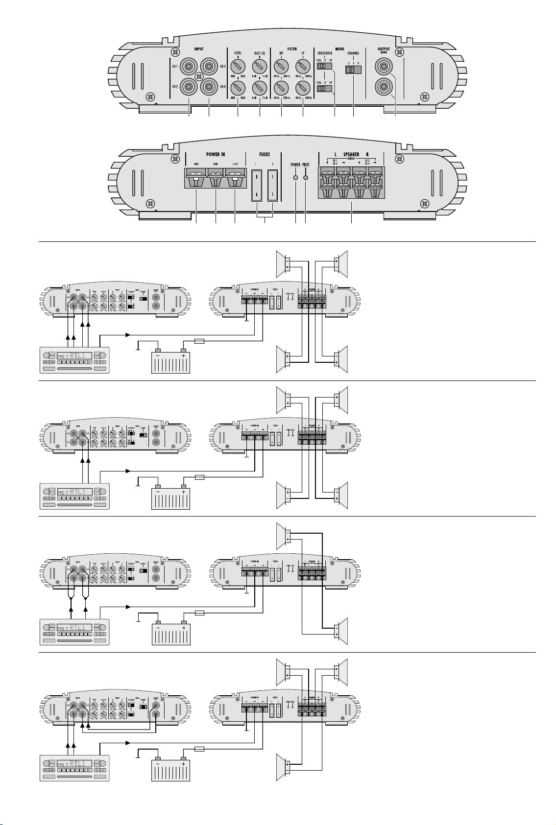
D 4-Kanalbetrieb
GB 4-channel operation
F Mode 4 canaux
I Funzionamento a 4 canali
NL 4-kanaals werking
E Modo 4 canales
PL Praca czterokanałowa
D Aktiver 2-Wegebetrieb
GB Active 2-way operation
F Mode actif 2 voies
I Funzionamento attivo a 2 vie
NL Actieve 2-kanaals werking
E Funcionamiento activo de 2 vías
PL Praca w układzie dwudrożnym aktywnym
➂
➃
3
RL
TP
Tre
Bass
1 2 3 4 5 6 7 8
EJECT CD / RADIO
TP
Tre
Bass
1 2 3 4 5 6 7 8
EJECT CD / RADIO
CD
FM
AM
RL
CD
FM
AM
On = 12 V
Chassis
Menu
Radio Battery
On = 12 V
Chassis
Menu
Radio Battery
Fuse
50 A
Fuse
50 A
Chassis
Speaker L
Chassis
Subwoofer
min. 2 Ω
min. 2 Ω
Speaker R
min. 4 Ω
Speaker R
min. 2 Ω
D Alle Kanäle im Brückenbetrieb
GB All channels in bridge operation
F Tous les canaux en mode bridgé
I Tutti i canali con funzionamento a ponte
NL Alle kanalen in brugschakeling
E Todos los canales en modo punteado
PL Wszystkie kanały w układzie mostka
D 3-Kanalbetrieb
GB 3-channel operation
F Mode 3 canaux
I Funzionamento a 3 canali
NL 3-kanaals werking
E Modo 3 canales
PL Praca trójkanałowa
➄
➅
Page 4

4-Kanal-Car-HiFi-Endstufe
Diese Anleitung richtet sich an Fachleute mit
Kenntnissen in der Kfz-Elektrik (alle Kapi-
Deutsch
tel) und an Benutzer ohne besondere Fachkenntnisse (Kapitel 3 und 4). Bitte lesen Sie
die Anleitung vor der Installation gründlich
durch und heben Sie sie für ein späteres Nachlesenauf.
Auf der ausklappbaren Seite 3 finden
Sie alle beschriebenen Bedienelemente und
Anschlüsse.
1 Einsatzmöglichkeiten
Die Endstufe HPB-604 ist speziell für CarHiFi- Anlagen konzipiert und kann vier FullRange- Lautsprecher (2- oder 3-Wege-Lautsprecher) antreiben. Durch die integrierten
Frequenzweichen lässt sich auch ein aktives
2-Wege-System mit zwei Mittelhochtönern
und zwei Basslautsprechern oder einem Subwoofer realisieren (Bi-Amping).
Um eine größere Ausgangsleistung zu
erhalten, können die Kanäle 1, 2 und / oder 3,
4 im Brückenbetrieb jeweils einen 4-Ω-Lautsprecher antreiben.
Inhalt
1 Einsatzmöglichkeiten . . . . . . . . 4
2 Übersicht . . . . . . . . . . . . . . 4
2.1 Frontseite . . . . . . . . . . . . . . .4
2.2 Rückseite . . . . . . . . . . . . . . . 4
3 Sicherheitshinweise. . . . . . . . .4
4 Vorsicht bei hohen Lautstärken . . 4
5 Montage. . . . . . . . . . . . . . . 4
6 Endstufe anschließen . . . . . . . .5
6.1 Stromversorgung . . . . . . . . . . . 5
6.1.1 Betriebsspannung . . . . . . . . . 5
6.1.2 Masseanschluss. . . . . . . . . . .5
6.1.3 Steuerspannung zum Einschalten. .5
6.2 Eingänge . . . . . . . . . . . . . . . 5
6.2.1 4-Kanalbetrieb (Abb. 3). . . . . . . 5
6.2.2 Aktiver 2-Wegebetrieb (Abb. 4). . .5
6.2.3 Brückenbetrieb (Abb. 5) . . . . . . 5
6.2.4 3-Kanalbetrieb (Abb. 6). . . . . . . 5
6.3 Line-Ausgang . . . . . . . . . . . . .5
6.4 Lautsprecher . . . . . . . . . . . . . 5
6.4.1 4-Kanalbetrieb . . . . . . . . . . . 5
6.4.2 Aktiver 2-Wegebetrieb . . . . . . . 5
6.4.3 Brückenbetrieb . . . . . . . . . . . 5
6.4.4 3-Kanalbetrieb . . . . . . . . . . . 6
7 Inbetriebnahme . . . . . . . . . . . 6
7.1 Filter auswählen und
Trennfrequenzen einstellen
7.2 Pegel und Bassanhebung einstellen . .6
8 Fehlerbeseitigung. . . . . . . . . .6
9 Technische Daten . . . . . . . . . . 6
. . . . . . 6
2 Übersicht
2.1 Frontseite
1
Cinch-Buchsen CH 1 und CH 2 für die
Eingangssignale der Kanäle 1 und 2
2
Cinch-Buchsen CH 3 und CH 4 für die
Eingangssignale der Kanäle 3 und 4
3
Trimmregler LEVEL zur Eingangspegelanpassung:
oberer Regler für die Kanäle 1 und 2,
unterer Regler für die Kanäle 3 und 4
4 Trimmregler BASS EQ zur Bassanhebung
bis 12 dB bei 50 Hz:
oberer Regler für die Kanäle 1 und 2,
unterer Regler für die Kanäle 3 und 4
5 Trimmregler HP zum Einstellen der Trenn-
frequenz des Hochpasses:
oberer Regler für die Kanäle 1 und 2,
unterer Regler für die Kanäle 3 und 4
6 Trimmregler LP zum Einstellen der Trenn-
frequenz des Tiefpasses:
oberer Regler für die Kanäle 1 und 2,
unterer Regler für die Kanäle 3 und 4
7
Schalter CROSSOVER zur Auswahl der Filter:
oberer Schalter für die Kanäle 1 und 2,
unterer Schalter für die Kanäle 3 und 4
FULL für Full-Range-Lautsprecher, kein
Filter eingeschaltet
LP für Basslautsprecher oder einen Sub-
woofer, Tiefpass eingeschaltet
HP für Mittelhochtöner, Hochpass ein-
geschaltet
8 Schalter für den Betriebsmodus
„2“
für aktiven 2-Wegebetrieb: nur die Eingänge 3 und 4 anschließen (Abb. 4),
Kanal 1 erhält das Signal vom Eingang 3 und Kanal 2 vom Eingang 4
„3“ 3-Kanalbetrieb: Kanäle 1 und 2 arbei-
ten separat, Kanäle 3 und 4 werden
im Brückenbetrieb zum Antreiben
eines Subwoofers genutzt (Abb.6)
„4“ 4-Kanalbetrieb: jeder Kanal wird
über einen eigenen Eingang angesteuert (Abb. 3)
9
Line-Ausgänge OUTPUT zum Anschluss
eines Subwoofer-Verstärkers oder zum
Anschluss der Eingänge 3 und 4 (Abb.6)
An beiden Buchsen liegt das durchgeschleifte Eingangssignal der Eingänge 1 – 4
in Mono an.
2.2 Rückseite
10 Masseanschluss GND
11 Steuereingang REM zum Einschalten der
Endstufe über eine 12-V-Spannung
12
Anschluss für die Versorgungsspannung
+12 V
13 Sicherungen 2 × 25 A
Eine durchgebrannte Sicherung nur durch
eine gleichen Typs ersetzen!
14 Betriebsanzeige POWER
15
Anzeige PROT. leuchtet bei aktivierter
Schutzschaltung:
1. wenn an einem der Lautsprecherausgänge (16) ein Kurzschluss aufgetretenist
2. wenn die Endstufe überhitzt ist
16 Lautsprecheranschlüsse SPEAKER
3 Sicherheitshinweise
Die Endstufe entspricht allen relevanten
Richtlinien der EU und trägt deshalb das
-Zeichen.
Beim Anschluss der Car-HiFi-Endstufe an
•
die Autobatterie ist besondere Sorgfalt
geboten. Bei Kurzschlüssen können sehr
gefährlich hohe Ströme fließen. Schrauben
Sie deshalb unbedingt vor dem Anschluss
die Minus klemme der Autobatterie ab.
Die Endstufe muss fest und fachgerecht an
•
einer mechanisch stabilen Stelle im Auto
montiert werden, damit sie sich nicht löst
und zu einem gefährlichen Geschoss wird.
Während des Betriebs kann das Gerät sehr
•
heiß werden. Platzieren Sie darum keine
hitze empfindlichen Gegenstände in der
Nähe und berühren Sie die Endstufe nicht
während des Betriebs.
Verwenden Sie für die Reinigung nur ein
•
trockenes, weiches Tuch, auf keinen Fall
Chemikalien oder Wasser.
Wird das Gerät zweckentfremdet, nicht
•
richtig angeschlossen, falsch bedient oder
nicht fachgerecht repariert, kann keine Haftung für daraus resultierende Sach- oder
Personenschäden und keine Garantie für
das Gerät übernommen werden.
Soll das Gerät endgültig aus dem
Betrieb genommen werden, übergeben Sie es zur umweltgerechten
Entsorgung einem örtlichen Recyclingbetrieb.
4 Vorsicht bei hohen
Lautstärken
Stellen Sie die Lautstärke nie sehr hoch
•
ein. Extrem hohe Lautstärken können das
Gehör schädigen.
Das Ohr gewöhnt sich an hohe Lautstär-
•
ken und empfindet sie nach einiger Zeit
als nicht mehr so hoch. Erhöhen Sie darum
eine einmal eingestellte hohe Lautstärke
nach der Gewöhnung nicht weiter.
Während des Autofahrens dürfen Sig-
•
naltöne, z. B. von einem Rettungswagen,
nicht durch eine zu hohe Lautstärke der
Car-HiFi-Anlage übertönt werden.
Bei ausgeschaltetem Motor sollte die Car-
•
HiFi- Anlage nicht längere Zeit mit hoher
Lautstärke betrieben werden. Die Autobatterie wird schnell entladen und liefert dann
eventuell nicht mehr genügend Energie
zum Starten.
5 Montage
Bei der Auswahl des Montageplatzes unbedingt die folgenden Punkte beachten:
Das 12-V-Stromversorgungskabel von der
•
Batterie zur Car-HiFi-Endstufe sollte so kurz
wie möglich sein. Es ist günstiger, längere
Lautsprecherkabel zu verwenden und dafür
ein kürzeres Stromversorgungskabel.
Die Masseleitung von der Endstufe zum
•
Fahrzeugchassis sollte ebenfalls so kurz wie
möglich sein.
4
Page 5

Um die entstehende Wärme der Car-HiFi-
•
Endstufe ableiten zu können, muss eine
ausreichende Belüftung gewährleistet sein.
Wegen der beim Bremsen auftretenden
•
Kräfte muss die Endstufe an einer mechanisch stabilen Stelle fest angeschraubt
werden.
Die Sicherungen und die Regler müssen
•
zugänglich sein.
Die Endstufe sollte elektrisch isoliert vom
Fahrzeugchassis montiert werden. Die Endstufe mit den vier Befestigungswinkeln an
geeigneter Stelle festschrauben.
6 Endstufe anschließen
Der Anschluss der Car-HiFi-Endstufe an das
•
Bordnetz darf nur durch qualifiziertes Fachpersonal erfolgen.
Unbedingt vor dem Anschluss die Minus-
•
klemme der Autobatterie abschrauben, um
bei einem eventuellen Kurzschluss während
der Installation Schäden zu vermeiden.
Die erforderlichen Kabel so verlegen, dass
•
deren Isolierung nicht beschädigt werden
kann.
Der gesamte Anschluss ist in den Abbildungen 3 – 6 auf der Seite 3 dargestellt.
6.1 Stromversorgung
6.1.1 Betriebsspannung
Den Anschluss „+12V“ (12) über ein Starkstromkabel mit der Plusklemme der Autobatterie verbinden. Um den Spannungsverlust durch
das Kabel gering zu halten, sollte mindestens
ein Querschnitt von 8 mm2 verwendet werden, z. B. CPC-100 / RT. Um die neu verlegte
12-V-Leitung gegen einen Kurzschluss abzusichern, muss eine 50-A-Vorsicherung in unmittelbarer Nähe der Batterie zwischengesetzt
werden (max. Kabellänge zur Batterie 20 cm).
Zur Stabilisierung der Betriebsspannung
für die Endstufe und der damit verbundenen
Leistungssteigerung sowie Klangverbesserung
wird ein Power-Kondensator empfohlen.
6.1.2 Masseanschluss
Den Masseanschluss GND (10) über ein Starkstromkabel mit einem Querschnitt von mindestens 8 mm2 (z. B. CPC-100 / SW) mit der
Masse des Autos oder besser direkt mit der
Minus klemme der Autobatterie verbinden.
Hinweise:
1. Bei Verwendung der Karosserie als Masseanschluss
muss die verwendete Stelle einen guten elektrischen Kontakt zur Hauptkarosserie aufweisen (z. B.
durch ausreichend viele Schweißpunkte). Eventueller Lack am Kontaktpunkt muss vollständig
entfernt werden.
2. Zur Vermeidung von Masseschleifen muss die
Masse des Autoradios an die Stelle gelegt werden,
an der auch die Endstufe an Masse liegt.
6.1.3 Steuerspannung zum Einschalten
Die Car-HiFi-Endstufe wird durch eine Steuerspannung von +12 V am Anschluss REM (11)
ein- und ausgeschaltet. Den Anschluss REM
mit dem 12-V-Schaltausgang vom Auto radio
verbinden (z. B. Anschluss für eine Motorantenne, eventuell mit der Motorantenne
parallel schalten).
6.2 Eingänge
Die beiden Eingangsbuchsen INPUT (2)
über Cinch-Kabel mit den entsprechenden
Line-Ausgängen am Autoradio verbinden.
Sind am Autoradio keine Line-Ausgänge vorhanden, können die Lautsprecherausgänge
des Autoradios über einen Audio-Übertrager (z. B. FGA-22HQ) mit den Eingängen der
Endstufe verbunden werden. Der Anschluss
richtet sich nach der gewünschten Betriebsart
der Endstufe:
6.2.1 4-Kanalbetrieb (Abb. 3)
Den Schalter CHANNEL (8) für den 4-KanalBetrieb in die Position „4“ stellen. Die Ausgänge des Autoradios wie folgt mit den
Eingängen INPUT CH 1 bis CH 4 (1 und 2)
verbinden:
Front links auf Kanal 1
Front rechts auf Kanal 2
Rear links auf Kanal 3
Rear rechts auf Kanal 4
Sind am Autoradio keine Ausgänge für die hinteren Kanäle (Rear) vorhanden, den Ausgang
des linken Kanals über ein Y-Kabel (z. B. CBA25 / SW) mit den Eingangsbuchsen der Kanäle 1
und 3 verbinden und den Ausgang des rechten
Kanals über ein weiteres Y-Kabel mit den Eingangsbuchsen der Kanälen 2 und4.
6.2.2 Aktiver 2-Wegebetrieb (Abb. 4)
Den Schalter CHANNEL (8) für den aktiven
2-Wegebetrieb in die Position „2“ stellen. Die
Ausgänge des Autoradios mit den Eingängen
INPUT CH 3 und CH 4 (2) verbinden:
linker Kanal auf Kanal 3
rechter Kanal auf Kanal 4
Der Kanal 1 erhält das Signal vom Eingang 3
und der Kanal 2 vom Eingang 4.
6.2.3 Brückenbetrieb (Abb. 5)
Sollen die Kanäle 1 und 2 in Brückenschaltung den linken Lautsprecher antreiben sowie
die Kanäle 3 und 4 in Brückenschaltung den
rechten Lautsprecher, den Ausgang des linken
Kanals am Autoradio über ein Y-Kabel (z. B.
CBA-25 / SW) mit den Eingängen INPUT CH1
und CH2 (1) verbinden und den Ausgang des
rechten Kanals über ein weiteres Y-Kabel mit
den Eingängen INPUT CH 3 und CH 4 (2). Den
Schalter CHANNEL (8) hierfür in die Position
„4“ stellen.
6.2.4 3-Kanalbetrieb (Abb. 6)
Den Schalter CHANNEL (8) für den 3-Kanalbetrieb in die Position „3“ stellen. Die Ausgänge des Autoradios wie folgt mit den Eingängen INPUT (1 und 2) verbinden:
linker Kanal auf Kanal 1
rechter Kanal auf Kanal 2
Subwoofer L auf Kanal 3
Subwoofer R auf Kanal 4
Sind am Autoradio keine Ausgänge für einen
Subwoofer-Verstärker vorhanden, die Eingänge der Kanäle 3 und 4 mit den beiden
Buchsen OUTPUT (9) verbinden (siehe Abb. 6).
6.3 Line-Ausgang
An den beiden Buchsen OUTPUT (9) liegt das
Monosignal der Eingänge 1 – 4 an. Soll ein
Subwoofer-Verstärker in die Car-HiFi-Anlage
eingesetzt werden und sind am Autoradio
keine Ausgänge für einen Subwoofer-Verstärker vorhanden, können die Eingänge des
Subwoofer-Verstärkers an die Buchsen OUTPUT angeschlossen werden (siehe ggf. auch
Kap. 6.2.4).
6.4 Lautsprecher
Es lassen sich Full-Range-Lautsprecher (2- oder
3-Wege-Lautsprecher), Mittelhochtöner, Basslautsprecher oder ein Subwoofer betreiben.
Wichtig! Alle Lautsprecher müssen 2-polig
angeschlossen werden, d. h. ohne gemeinsamen Masseanschluss. Bei der Auswahl
geeigneter Lautsprecher unbedingt deren
mechanische und elektrische Belastbarkeit
im Zusammenhang mit der genutzten Endstufenleistung berücksichtigen (siehe auch
technische Daten Seite 6
).
Die größte Ausgangsleistung wird beim Anschluss von 2-Ω-Lautsprechern oder einer
Lautsprechergruppe mit einer Gesamtimpedanz von 2 Ω pro Kanal erreicht (z. B. zwei
4-Ω-Lautsprecher parallel geschaltet). Es
können jedoch auch einzelne 4-Ω-Lautsprecher angeschlossen werden, wobei sich die
Ausgangsleistung etwas verringert.
Achtung! Die Impedanz der Lautsprecher
bzw. die Gesamtimpedanz von Lautsprechergruppen, die im Brückenbetrieb angetrieben werden, darf 4 Ω nicht unterschreiten!
Die Lautsprecher an die Klemmen SPEAKER
(16) anschließen. Der genaue Anschluss richtet sich nach der gewünschten Betriebsart
der Endstufe:
6.4.1 4-Kanalbetrieb
Siehe auch Abb. 3.
CH 1 L+ Pluspol Lautsprecher links vorne
CH 1 L− Minuspol Lautsprecher links vorne
CH 2 R+ Pluspol Lautsprecher rechts vorne
CH 2 R− Minuspol Lautsprecher rechts vorne
CH 3 L+ Pluspol Lautsprecher links hinten
CH 3 L− Minuspol Lautsprecher links hinten
CH 4 L+ Pluspol Lautsprecher rechts hinten
CH 4 L− Minuspol Lautsprecher rechts hinten
6.4.2 Aktiver 2-Wegebetrieb
Siehe auch Abb. 4.
CH 1 L+ Pluspol linker Basslautsprecher
CH 1 L− Minuspol linker Basslautsprecher
CH 2 R+ Pluspol rechter Basslautsprecher
CH 2 R− Minuspol rechter Basslautsprecher
CH 3 L+ Pluspol linker Mittelhochtöner
CH 3 L− Minuspol linker Mittelhochtöner
CH 4 L+ Pluspol rechter Mittelhochtöner
CH 4 L− Minuspol rechter Mittelhochtöner
6.4.3 Brückenbetrieb
Beim Anschluss die Beschriftung „BRIDGE“
beachten, siehe auch Abb. 5.
CH 1 L+ Pluspol linker Lautsprecher
CH 1 L− bleibt frei
CH 2 R+ bleibt frei
CH 2 R− Minuspol linker Lautsprecher
CH 3 L+ Pluspol rechter Lautsprecher
CH 3 L− bleibt frei
CH 4 L+ bleibt frei
CH 4 L− Minuspol rechter Lautsprecher
Deutsch
5
Page 6

6.4.4 3-Kanalbetrieb
Siehe auch Abb. 6.
CH 1 L+ Pluspol linker Lautsprecher
CH 1 L− Minuspol linker Lautsprecher
Deutsch
CH 2 R+ Pluspol rechter Lautsprecher
CH 2 R− Minuspol rechter Lautsprecher
CH 3 L+ Pluspol Subwoofer
CH 3 L− bleibt frei
CH 4 L+ bleibt frei
CH 4 L− Minuspol Subwoofer
7 Inbetriebnahme
Wichtig! Vor dem ersten Einschalten die Fil-
ter mit dem CROSSOVER (7) auswählen und
die Trennfrequenz grob einstellen (Kap.7.1),
damit die Lautsprecher nicht durch einen
eventuell zu großen Frequenzbereich überlastet werden. Auch sollte die komplette
Verdrahtung der Car-HiFi-Endstufe noch einmal auf Richtigkeit überprüft werden. Erst
danach die Minusklemme der Autobatterie
wieder anschließen.
7.1 Filter auswählen und Trennfrequenzen einstellen
Je nach angeschlossenen Lautsprechertypen
mit den Schaltern CROSSOVER (7) die Filter
auswählen. Der obere Schalter und die oberen
Regler sind zum Einstellen der Kanäle 1 und
2, der untere Schalter und die unteren Regler
für die Kanäle 3 und 4.
Für Full-Range-Lautsprecher den Schalter
ganz nach links in die Position FULL schieben.
Die Endstufe gibt den gesamten Frequenzbe
reich wieder.
Für Basslautsprecher oder einen Subwoofer
den Schalter in die Position LP schieben. Der
Tiefpass ist eingeschaltet und die mittleren
sowie hohen Frequenzen werden unterdrückt.
Die Trennfrequenz mit dem Regler LP (6) zunächst grob einstellen.*
Für Mittelhochtöner den Schalter in die
Position HP schieben. Der Hochpass ist eingeschaltet und die tiefen Frequenzen werden
damit unterdrückt. Die Trennfrequenz mit
dem Regler HP (5) zunächst grob einstellen.*
* Zur Orientierung den Frequenzbereich der einge-
setzten Lautsprecher beachten. Die Feineinstellung
erfolgt nach der Pegeleinstellung mit entsprechenden Messgeräten.
7.2 Pegel und Bassanhebung einstellen
Tipp Um Störeinstrahlungen durch die Au-
toelektrik so gering wie möglich zu halten,
sollte der Ausgangspegel der Signalquelle
min. 1,5 V betragen.
1)
Die beiden Regler LEVEL (3) ganz nach links
in die Position MIN drehen.
2) Die Car-HiFi-Anlage komplett einschalten.
Die grüne Betriebsanzeige POWER (14)
leuchtet. Die Endstufe bleibt jedoch noch
für ca. 3 s stumm geschaltet (Einschaltverzögerung).
3) Die Signalquelle, z. B. das Autoradio, auf
maximale, nicht verzerrende Lautstärke
einstellen.
4) Die Regler LEVEL maximal so weit aufdrehen, dass keine Verzerrungen auftreten.
(Die oberen Regler sind zum Einstellen der
Kanäle 1 und 2 und die unteren für die
Kanäle 3 und 4.)
Beim 4-Kanalbetrieb lässt sich mit
den Reglern auch die Balance zwischen
den vorderen und hinteren Lautsprechern
einstellen, falls am Autoradio dafür kein
Regler vorhanden ist.
Beim aktiven 2-Wegebetrieb und beim
3-Kanalbetrieb mit den Reglern einen
natür lichen Klang einstellen: Sind die Bässe
zu leise, die Kanäle für die Mittelhochtöner
im Pegel reduzieren. Bei einem zu kräftigen
Bass die Lautstärke der Basskanäle bzw.
des Sub woofer-Kanals verringern.
5) Bei Bedarf lassen sich die Bässe mit dem
entsprechenden Regler BASS EQ (4) anheben (max. 12 dB / 50 Hz).
6)
Sind in der Car-HiFi-Anlage weitere Endstufen eingesetzt, zur Anpassung der Lautstärke aller Kanäle untereinander die jeweils zu lauten Kanäle im Pegel reduzieren.
8 Fehlerbeseitigung
Ist nach dem Einschalten der Car-HiFi-Anlage
kein Ton zu hören, den Fehler mithilfe der beiden LEDs POWER (14) und PROT. (15) näher
lokalisieren.
Die LED POWER leuchtet nicht
1)
Die Sicherungen (13) der Car-HiFi-Endstufe
(2 × 25 A) und die Vorsicherung (50 A) an
der Autobatterie überprüfen. Defekte
Sicherungen auswechseln. Nur Sicherungen mit den angegebenen Werten verwenden. Auf keinen Fall einen höheren Wert
einsetzen. Die Endstufe kann beschädigt
werden und die Garantie erlischt.
2)
Das 12-V-Stromversorgungskabel sowie
das Massekabel auf korrekten Anschluss
und Unterbrechung kontrollieren.
3)
An der Klemme REM (11) der Endstufe
messen, ob +12 V anliegt. Wenn nicht,
die Leitung an der Klemme REM entfer
nen und vorübergehend die Klemmen REM
und „+12V“ (12) überbrücken. Schaltet
die Endstufe jetzt ein, liegt der Fehler
in der fehlenden Steuerspannung. Den
12-V-Schaltausgang des Autoradios und
das entsprechende Anschlusskabel zur
Endstufe überprüfen.
Die LED POWER leuchtet
1)
Steht der Schalter CHANNEL (8) in der richtigen Position? Siehe Kap. 6.2.1 bis 6.2.4.
2) Die Cinch-Leitungen von der Signalquelle
zur Car-HiFi-Endstufe überprüfen. Sind die
Stecker richtig eingesteckt? Sind die Leitun
gen unterbrochen?
3)
Die Signalquelle überprüfen. Ist die Signalquelle eingeschaltet? Sind die richtigen
Ausgänge verwendet worden? Ist die Signalquelle defekt?
4) Die Lautsprecherkabel auf Unterbrechung
überprüfen.
5)
Die angeschlossenen Lautsprecher überprüfen.
Die LED PROT. leuchtet
Die Endstufe ist mit einer Schutzschaltung
gegen Kurzschluss an den Lautsprecherausgängen und gegen Überhitzung gesichert. Ist
die Schutzschaltung aktiviert, leuchtet die Anzeige PROT.(15). Bei einer Überhitzung schaltet die Endstufe nach dem Abkühlen automatisch wieder ein. Bei einem Kurzschluss
an den Lautsprecherausgängen muss nach
der Fehlerbeseitigung zum Zurücksetzen der
Schutzschaltung die 12-V-Steuerspannung
kurz abgeschaltet werden (z. B. Autoradio
ausschalten).
9 Technische Daten
Ausgangsleistung
Gesamtleistung (Pmax): � � � �700 W
4-Kanalbetrieb an 2 Ω: � � � �4 × 100 W Sinus
4-Kanalbetrieb an 4 Ω: � � � �4 × 75 W Sinus
Brückenbetrieb an 4 Ω: � � � �2 × 200 W Sinus
Frequenzbereich:
min� Lautsprecherimpedanz
4-Kanalbetrieb: � � � � � � � � � �2 Ω
Brückenbetrieb: � � � � � � � � � �4 Ω
Eingänge: � � � � � � � � � � � � � � �4 × Cinch
Empfindlichkeit: � � � � � � � � � �0,4 – 4 V
Impedanz: � � � � � � � � � � � � � �20 kΩ
Kanaltrennung: � � � � � � � � � � �> 45 dB
Störabstand: � � � � � � � � � � � � �> 93 dB (bewertet)
Klirrfaktor: � � � � � � � � � � � � � � �< 0,2 %
Tiefpässe: � � � � � � � � � � � � � � �40 – 300 Hz,
Hochpässe: � � � � � � � � � � � � � �40 – 500 Hz,
Bassanhebung: � � � � � � � � � � �0 – 12 dB / 50 Hz
-
Stromversorgung: � � � � � � � � �10 – 16 V (⎓) / 50 A
Einsatztemperatur: � � � � � � � � �0 – 40 °C
Abmessungen (B × H × T): � � �252 × 62 × 400 mm
Gewicht: � � � � � � � � � � � � � � � �3,2 kg
Änderungen vorbehalten.
� � � � � � � � � �20 – 20 000 Hz
6 dB / Oktave
6 dB / Oktave
-
Diese Bedienungsanleitung ist urheberrechtlich für MONACOR ® INTERNATIONAL GmbH & Co. KG geschützt.
Eine Reproduktion für eigene kommerzielle Zwecke – auch auszugsweise – ist untersagt.
6
Page 7

4-Channel Car HiFi
PowerAmplifier
These instructions are intended for experts
with knowledge in the electrical system of
cars (all chapters) and users without any specific knowledge (chapters 3 and 4). Please
read the instructions carefully prior to installation and keep them for later reference.
All operating elements and connections
described can be found on the fold-out
page3.
1 Applications
The power amplifier HPB-604 has especially
been designed for car HiFi systems and is able
to drive four full range speakers (2-way or
3-way speakers). Due to the integrated crossover networks, it is also possible to implement
an active 2-way system with two mid-high
range speakers and two bass speakers or a
subwoofer (bi-amping).
To obtain a higher output power, the
channels 1, 2 and / or 3, 4 can drive one 4 Ω
speaker each in bridge operation.
Contents
1 Applications . . . . . . . . . . . . .7
2 Operating Elements
and Connections . . . . . . . . . . 7
2.1 Front panel . . . . . . . . . . . . . . 7
2.2 Rear panel . . . . . . . . . . . . . . 7
3 Safety Notes. . . . . . . . . . . . .7
4 Caution with High Volumes . . . . 7
5 Installation . . . . . . . . . . . . . 7
6 Connection of the
Power Amplifier. . . . . . . . . . .8
6.1 Power supply . . . . . . . . . . . . . 8
6.1.1 Operating voltage . . . . . . . . . 8
6.1.2 Ground connection. . . . . . . . .8
6.1.3 Control voltage for switching-on . . 8
6.2 Inputs. . . . . . . . . . . . . . . . . 8
6.2.1 4-channel operation (fig. 3). . . . . 8
6.2.2 Active 2-way operation (fig. 4) . . . 8
6.2.3 Bridge operation (fig. 5) . . . . . . 8
6.2.4 3-channel operation (fig. 6). . . . . 8
6.3 Line output . . . . . . . . . . . . . . 8
6.4 Speakers . . . . . . . . . . . . . . . 8
6.4.1 4-channel operation . . . . . . . . 8
6.4.2 Active 2-way operation . . . . . . .8
6.4.3 Bridge operation . . . . . . . . . . 8
6.4.4 3-channel operation . . . . . . . . 8
7 Setting into Operation . . . . . . . 9
7.1 Selecting the filters and adjusting the
crossover frequencies . . . . . . . . .9
7.2 Adjusting the level and
thebassboosting . . . . . . . . . . .9
8 Troubleshooting. . . . . . . . . . .9
9 Specifications . . . . . . . . . . . . 9
2 Operating Elements
and Connections
2.1 Front panel
1 RCA jacks CH 1 and CH 2 for the input
signals of the channels 1 and 2
2 RCA jacks CH 3 and CH 4 for the input
signals of the channels 3 and 4
3
Trimming controls LEVEL for input level
matching:
upper control for the channels 1 and 2,
lower control for the channels 3 and 4
4
Trimming controls BASS EQ for bass boosting up to 12 dB at 50 Hz:
upper control for the channels 1 and 2,
lower control for the channels 3 and 4
5
Trimming controls HP for adjusting the
crossover frequency of the high pass:
upper control for the channels 1 and 2,
lower control for the channels 3 and 4
6
Trimming controls LP for adjusting the
crossover frequency of the low pass:
upper control for the channels 1 and 2,
lower control for the channels 3 and 4
7
CROSSOVER switches for selecting the
filters:
upper switch for the channels 1 and 2,
lower switch for the channels 3 and 4
FULL for full range speakers, no filter
switched on
LP for bass speakers or a subwoofer,
low pass switched on
HP for mid-high range speakers, high
pass switched on
8 Switch for the operating mode
“2” for active 2-way operation: only
connect the inputs 3 and 4 (fig. 4),
channel 1 receives the signal from
input 3 and channel 2 from input 4
“3” 3-channel operation: channels 1
and 2 operate separately, channels
3 and 4 are used in bridge operation
to drive a subwoofer (fig. 6)
“4” 4-channel operation: each channel is
driven via an individual input (fig.3)
9
Line jacks OUTPUT for connection of a
subwoofer amplifier or for connection of
the inputs 3 and 4 (fig. 6)
The fed-through input signal of the inputs
1 to 4 is available in mono at both jacks.
2.2 Rear panel
10 Ground terminal GND
11
Control input REM for switching on the
power amplifier via a 12 V voltage supply
12 Connection for the supply voltage +12 V
13 Fuses 2 × 25 A
Only replace a blown fuse by one of the
same type!
14 POWER LED
15 LED PROT. lights up when the protective
circuit has been activated:
1. if a short circuit has occurred at one of
the speaker outputs (16)
2. if the power amplifier is overheated
16 Terminals SPEAKER
3 Safety Notes
The power amplifier corresponds to all relevant directives of the EU and is therefore
marked with .
Be very careful when connecting the car
•
HiFi power amplifier to the battery. Risk of
short circuit and dangerous high voltage!
Therefore, always screw off the negative
terminal from the car battery prior to connecting the power amplifier.
The power amplifier must be installed at
•
a mechanically stable place in the car. It
must be skilfully fixed so that it does not get
loose and turn into a dangerous projectile.
During operation, the unit may become
•
very hot. Therefore, do not place any objects sensitive to heat near the unit and
do not touch the power amplifier while in
operation.
For cleaning only use a dry, soft cloth; never
•
use chemicals or water.
No guarantee claims for the unit and no
•
liability for any resulting personal damage
or material damage will be accepted if the
unit is used for other purposes than originally intended, if it is not correctly connected or operated, or if it is not repaired
in an expert way.
If the unit is to be put out of operation definitively, take it to a local
recycling plant for a disposal which
will not be harmful to the environment.
4 Caution with High Volumes
Never adjust a very high volume. Extremely
•
high volumes may damage your hearing.
Your ear will accustomed to high volumes
•
which do not seem to be that high after
some time. Therefore, do not increase a
high volume after getting used to it.
While driving in the car, signal sounds, e. g.
•
by an ambulance, must not be drowned by
the car HiFi system which has been set to a
very high volume.
With the motor switched off, the car HiFi
•
system should not be in operation at high
volume for a longer period of time. The car
battery will quickly be discharged and may
not be able to supply sufficient energy for
starting the car.
5 Installation
When choosing the place of installation,
always observe the following:
The 12 V power supply cable from the bat-
•
tery to the car HiFi power amplifier should
be as short as possible. It is better to use
longer speaker cables and a shorter power
supply cable instead.
The ground cable from the power amplifier
•
to the chassis of the car should also be as
short as possible.
Sufficient air circulation is required to dissi-
•
pate the heat generated by the car HiFi power
amplifier.
English
7
Page 8

As forces occur during braking, the power
•
amplifier must tightly be screwed to a
mechanically stable place.
English
The fuses and the controls must be ac-
•
cessible.
The power amplifier should be installed electrically insulated from the car chassis. Tightly
screw the amplifier with the four fixing brackets at a suitable place.
6 Connection of the
Power Amplifier
The connection of the car HiFi power
•
amplifier to the electric system of the car
must only be carried out by authorized
personnel.
To prevent damage in case of a short circuit
•
during installation, always screw off the
negative terminal from the car battery prior
to connecting the power amplifier.
Lay the necessary cables so that their insu-
•
lation cannot be damaged.
The complete connection is shown in figs. 3
to 6 on page 3.
6.1 Power supply
6.1.1 Operating voltage
Connect the terminal “+12V” (12) via a highpower cable to the positive terminal of the car
battery. To keep the voltage loss by the cable
as low as possible, a minimum cross section
of 8 mm2 should be used, e. g. CPC-100 / RT.
To protect the newly laid 12 V cable against
a short circuit, insert an additional 50 A fuse
very close to the battery (max. cable length
to the battery 20 cm).
To stabilize the operating voltage for the
power amplifier and thus the resulting power
increase and sound improvement, a power
capacitor is recommended.
6.1.2 Ground connection
Connect the ground terminal GND (10) via
a high-power cable with a minimum cross
section of 8 mm2 (e. g. CPC-100 / SW) to the
ground of the car or perferably directly to the
negative terminal of the car battery.
Notes:
1. When using the chassis as a ground connection,
the place used must have a good electrical contact
to the main chassis (e. g. by a sufficient number
of welding points). Any lacquer at the point of
contact must completely be removed.
2. To avoid ground loops, the ground of the car radio
must be applied at the place where also the power
amplifier is grounded.
6.1.3 Control voltage for switching-on
The car HiFi power amplifier is switched on
and off by a control voltage of +12 V at the
terminal REM (11). Connect the terminal
REM to the 12 V control output of the car
radio (e. g. connection for a motor antenna,
if necessary, to be connected in parallel to the
motor antenna).
6.2 Inputs
Connect the two jacks INPUT (2) via cables
with RCA connectors to the corresponding
line outputs at the car radio. If the car radio
is not equipped with line outputs, the speaker
outputs of the car radio can be connected
via an transformer (e. g. FGA-22HQ) to the
inputs of the power amplifier. The connection
depends on the desired operating mode of
the power amplifier:
6.2.1 4-channel operation (fig. 3)
Set the switch CHANNEL (8) for the 4-channel operation to position “4”. Connect the
outputs of the car radio to the jacks INPUT
CH 1 to CH 4 (1 and 2) as follows:
front left to channel 1
front right to channel 2
rear left to channel 3
rear right to channel 4
If the car radio is not equipped with outputs
for the rear channels, connect the output
of the left channel via a Y cable (e. g. CBA25 / SW) to the input jacks of the channels 1
and 3 and the output of the right channel
via another Y cable to the input jacks of the
channels 2 and 4.
6.2.2 Active 2-way operation (fig. 4)
Set the switch CHANNEL (8) for the active
2-way operation to position “2”. Connect the
outputs of the car radio to the jacks INPUT
CH 3 and CH 4 (2):
left channel to channel 3
right channel to channel 4
The channel 1 receives the signal from input3
and the channel 2 from input 4.
6.2.3 Bridge operation (fig. 5)
If, in bridge operation, the channels 1 and 2
are to drive the left speaker, and if, in bridge
operation, the channels 3 and 4 are to drive
the right speaker, connect the output of the
left channel at the car radio via a Y cable (e. g.
CBA-25 / SW) to the jacks INPUT CH 1 and
CH 2 (1) and the output of the right channel
via another Y cable to the jacks INPUT CH 3
and CH 4 (2). For this purpose, set the switch
CHANNEL (8) to position “4”.
6.2.4 3-channel operation (fig. 6)
Set the switch CHANNEL (8) for the 3-channel operation to position “3”. Connect the
outputs of the car radio to the jacks INPUT (1
and 2) as follows:
left channel to channel 1
right channel to channel 2
subwoofer L to channel 3
subwoofer R to channel 4
If the car radio is not equipped with outputs
for a subwoofer amplifier, connect the inputs
of the channels 3 and 4 to the two jacks OUTPUT (9) [see fig. 6].
6.3 Line output
The mono signal of the inputs 1 to 4 is available at both jacks OUTPUT (9). If a subwoofer
amplifier is to be inserted into the car HiFi system and if the car radio is not equipped with
outputs for a subwoofer amplifier, the inputs
of the subwoofer amplifier can be connected
to the jacks OUTPUT (also see chapter 6.2.4,
if necessary).
6.4 Speakers
It is possible to use full range speakers (2-way
or 3-way speakers), mid-high range speakers,
bass speakers, or a subwoofer.
Important! All speakers must be connected
with 2 poles, i. e. without common ground
connection. When choos ing suitable speakers, pay attention to their mechanical and
electrical capability in con nection with the
power used of the power amplifier (also see
specifications page 9).
The highest output power is reached when
connecting 2 Ω speakers or a speaker group
with a total impedance of 2 Ω per channel
(e. g. two 4 Ω speakers connected in parallel).
However, it is also possible to connect individual 4 Ω speakers; in this case, the output
power is slightly reduced.
Attention! The impedance of the speakers
or the total impedance of speaker groups
which are driven in bridge operation must
not fall below 4 Ω!
Connect the speakers to the terminals
SPEAKER (16). The exact connection of the
speakers depends on the desired operating
mode of the power amplifier:
6.4.1 4-channel operation
Also see fig. 3.
CH 1 L+ positive pole speaker left front
CH 1 L− negative pole speaker left front
CH 2 R+ positive pole speaker right front
CH 2 R− negative pole speaker right front
CH 3 L+ positive pole speaker left rear
CH 3 L− negative pole speaker left rear
CH 4 L+ positive pole speaker right rear
CH 4 L− negative pole speaker right rear
6.4.2 Active 2-way operation
Also see fig. 4
CH 1 L+ positive pole left bass speaker
CH 1 L− negative pole left bass speaker
CH 2 R+ positive pole right bass speaker
CH 2 R− negative pole right bass speaker
CH 3 L+ positive pole
CH 3 L− negative pole
CH 4 L+ positive pole
CH 4 L− negative pole
left mid-high range speaker
left mid-high range speaker
right mid-high range speaker
right mid-high range speaker
6.4.3 Bridge operation
While connecting, pay attention to the lettering “BRIDGE”, also see fig. 5.
CH 1 L+ positive pole left speaker
CH 1 L− remains unconnected
CH 2 R+ remains unconnected
CH 2 R− negative pole left speaker
CH 3 L+ positive pole right speaker
CH 3 L− remains unconnected
CH 4 L+ remains unconnected
CH 4 L− negative pole right speaker
6.4.4 3-channel operation
Also see fig. 6
CH 1 L+ positive pole left speaker
CH 1 L− negative pole left speaker
CH 2 R+ positive pole right speaker
CH 2 R− negative pole right speaker
CH 3 L+ positive pole subwoofer
CH 3 L− remains unconnected
CH 4 L+ remains unconnected
CH 4 L− negative pole subwoofer
8
Page 9

7 Setting into Operation
Important! Prior to the first switching-on,
select the filters with the switch CROSSOVER(7) and coarsely adjust the crossover
frequency (chapter7.1) so that the speakers will not be overloaded by a frequency
range that might be too wide. It is also recommended to check first once again if the
entire wiring of the car HiFi power amplifier
is correct, and only then to connect the negative terminal of the car battery.
7.1 Selecting the filters and adjusting
the crossover frequencies
Depending on the speaker types connected,
select the filters with the switches CROSSOVER (7). The upper switch and the upper
controls are intended to adjust the channels
1 and 2, the lower switch and the lower controls are intended for the channels 3 and 4.
For full range speakers, set the switch to the
left stop to position FULL. The power amplifier
reproduces the entire frequency range.
For bass speakers or a subwoofer, set the
switch to position LP. The low pass is switched
on and the medium and high frequencies
are suppressed. For the time being, coarsely
adjust the crossover frequency with the control LP (6).*
For mid-high range speakers, set the switch
to position HP. The high pass is switched on
and the low frequencies are thus suppressed.
For the time being, coarsely adjust the crossover frequency with the control HP (5).*
* For a guidance, observe the frequency range of the
speakers used. The fine adjustment is made with
corresponding meters after the level adjustment.
7.2 Adjusting the level and
thebassboosting
Hint To keep the interference by the electric
system of the car as low as possible, the
output level of the signal source should be
1.5 V as a minimum.
1)
Turn both controls LEVEL (3) to the left stop
to position MIN.
2) Switch on the car HiFi system completely.
The green POWER LED (14) lights up. However, the power amplifier is muted for approx. 3 seconds (switch-on delay).
3)
Adjust the signal source, e. g. the car radio,
to the maximum, non-distorting volume.
4) Turn up the controls LEVEL to the non-dis-
torting maximum. (The upper controls are
intended to adjust the channels 1 and 2
and the lower controls are intended for
the channels 3 and 4.)
In 4-channel operation, it is also possible to adjust the balance between the front
and rear speakers if the car radio is not
equipped with a corresponding control.
In active 2-way operation, and 3-channel operation adjust a natural sound with
the controls: if the volume of the low fre-
quencies is too low, reduce the levels of the
channels for the mid-high range speakers.
If the volume of the bass frequencies is too
high, reduce the volume of the bass channels or of the subwoofer channel.
5)
If required, the bass frequencies can be
boosted with the corresponding control
BASS EQ (4) [max. 12 dB / 50 Hz].
6) If further power amplifiers are used in the
car HiFi system, reduce the levels of the
channels which are too high to match the
volumes of all channels with each other.
8 Troubleshooting
If there is no sound after switching on the car
HiFi system, locate the fault more precisely
by means of the two LEDs POWER (14) and
PROT. (15).
The LED POWER does not light up
1) Check the fuses (13) of the car HiFi amplifier (2 × 25 A) and the additional fuse (50 A)
at the car battery. Replace defective fuses.
Only use fuses with the indicated values.
Never insert a fuse of a higher value. The
power amplifier may be damaged and the
warranty will be void.
2)
Check the 12 V power supply cable and
the ground cable for correct connection
and for interruptions.
3)
Check at the terminal REM (11) of the
power amplifier if +12 V is available. If
not, remove the cable at the terminal REM
and temporarily bridge the terminals REM
and “+12V”(12). If the power amplifier
switches on now, the fault is due to the
missing control voltage. Check the 12 V
control output of the car radio and the
corresponding connection cable to the
power amplifier.
The LED POWER lights up
1) Is the switch CHANNEL (8) in the correct
position? See chapters 6.2.1 to 6.2.4.
2)
Check the cables with RCA connectors
from the signal source to the car HiFi
power amplifier. Are the plugs correctly
connected? Are the cables interrupted?
3)
Check the signal source. Is the signal source
switched on? Have the correct outputs
been used? Is the signal source defective?
4)
Check the speaker cables for interruptions.
5) Check the connected speakers.
LED PROT. lights up
The power amplifier is protected with a
protective circuit against short circuit at the
speaker outputs and against overheating.
If the protective circuit is activated, the LED
PROT. (15) lights up. In case of overheating,
the power amplifier automatically switches on
again after cooling down. In case of a short
circuit at the speaker outputs, after eliminating the error, the 12 V control voltage must
shortly be switched off (e. g. switch off the car
radio) to reset the protective circuit.
9 Specifications
Output power
Total power (Pmax): � � � � � � �700 W
4-channel operation at 2 Ω: �4 × 100 W RMS
4-channel operation at 4 Ω: �4 × 75 W RMS
Bridge operation at 4 Ω: � � �2 × 200 W RMS
Frequency range:
Min� speaker impedance
4-channel operation: � � � � � �2 Ω
Bridge operation: � � � � � � � �4 Ω
Inputs: � � � � � � � � � � � � � � � � �4 × RCA
Sensitivity: � � � � � � � � � � � � �0�4 – 4 V
Impedance: � � � � � � � � � � � � �20 kΩ
Channel separation: � � � � � � � �> 45 dB
S / N ratio: � � � � � � � � � � � � � � �> 93 dB (weighted)
THD: � � � � � � � � � � � � � � � � � � � < 0�2 %
Low passes: � � � � � � � � � � � � � �40 – 300 Hz,
High passes: � � � � � � � � � � � � �40 – 500 Hz,
Bass boosting: � � � � � � � � � � � �0 – 12 dB / 50 Hz
Power supply: � � � � � � � � � � � �10 – 16 V (⎓) / 50 A
Ambient temperature: � � � � � �0 – 40 °C
Dimensions (W × H × D): � � � �252 × 62 × 400 mm
Weight: � � � � � � � � � � � � � � � � �3�2 kg
Subject to technical modification.
� � � � � � � � � �20 – 20 000 Hz
6 dB / octave
6 dB / octave
English
All rights reserved by MONACOR ® INTERNATIONAL GmbH & Co. KG. No part of this instruction manual may
be reproduced in any form or by any means for any commercial use.
9
Page 10

Amplificateur Hi-Fi embarquée
4 canaux
Cette notice s’adresse à des personnes ex-
Français
pertes avec des connaissances dans les systèmes électriques de voiture (tous les chapitres) et à des utilisateurs sans connaissances
spécifiques (chapitres 3 et 4). Veuillez lire la
présente notice avec attention avant l’installation et conservez-la pour pouvoir vous y
reporter ultérieurement.
Vous trouverez sur la page 3, dépliable,
les éléments et branchements décrits.
1 Possibilités d’utilisation
L’amplificateur HPB-604 est spécialement
conçu pour une installation dans des systèmes
de Hi-Fi embarquée et peut faire fonctionner
quatre haut-parleurs Full Range (système 2 ou
3 voies). Grâce aux filtres de fréquences intégrés, il est possible d’obtenir un système actif
2 voies avec deux haut-parleurs médium aigu
et deux haut-parleurs de grave ou un subwoofer (bi-amplification). Pour obtenir une plus
grande puissance de sortie, les canaux 1, 2
et / ou 3, 4 peuvent faire fonctionner un hautparleur 4 Ω respectivement, en mode bridgé.
Table des matières
1 Possibilités d’utilisation . . . . . 10
2 Eléments et branchements . . . . 10
2.1 Face avant . . . . . . . . . . . . . 10
2.2 Face arrière . . . . . . . . . . . . . 10
3 Conseils d’utilisation
et desécurité . . . . . . . . . . . 10
4 Mises en garde en cas de volume
élevé . . . . . . . . . . . . . . . . 10
5 Montage. . . . . . . . . . . . . . 11
6 Branchements . . . . . . . . . . . 11
6.1 Alimentation . . . . . . . . . . . . 11
6.1.1 Tension de fonctionnement. . . . 11
6.1.2 Branchement masse . . . . . . . 11
6.1.3 Tension de commande
pour allumer . . . . . . . . . . . 11
6.2 Entrées . . . . . . . . . . . . . . . 11
6.2.1 Mode 4 canaux (schéma 3) . . . . 11
6.2.2 Mode 2 voies actif (schéma 4) . . 11
6.2.3 Mode bridgé (schéma 5) . . . . . 11
6.2.4 Mode 3 canaux (schéma 6) . . . . 11
6.3 Sortie Ligne . . . . . . . . . . . . . 11
6.4 Haut-parleurs . . . . . . . . . . . . 11
6.4.1 Mode quatre canaux . . . . . . . 11
6.4.2 Mode actif 2 voies . . . . . . . . 11
6.4.3 Mode bridgé . . . . . . . . . . . 12
6.4.4 Mode 3 canaux. . . . . . . . . . 12
7 Fonctionnement. . . . . . . . . . 12
7.1 Sélection des filtres et réglage des
fréquences de coupure . . . . . . . 12
7.2 Réglage de phase et
augmentation des graves . . . . . . 12
8 Solution des problèmes . . . . . 12
9 Caractéristiques techniques . . . 12
2 Eléments et branchements
2.1 Face avant
1 Prises RCA CH 1 et CH 2 pour les signaux
d’entrée des canaux 1 et 2
2 Prises RCA CH 3 et CH 4 pour les signaux
d’entrée des canaux 3 et 4
3 Réglages de réglage trimmer LEVEL pour
l’adaptation du niveau d’entrée :
réglage supérieur pour les canaux 1 et 2,
réglage inférieur pour les canaux 3 et 4
4
Réglages de réglage trimmer BASS EQ
pour l’augmentation des graves jusqu’à
12 dB à 50 Hz :
réglage supérieur pour les canaux 1 et 2,
réglage inférieur pour les canaux 3 et 4
5
Réglages de réglage trimmer HP pour
régler la fréquence de coupure du passehaut :
réglage supérieur pour les canaux 1 et 2,
réglage inférieur pour les canaux 3 et 4
6 Réglages de réglage trimmer LP pour ré-
gler la fréquence de coupure du passebas:
réglage supérieur pour les canaux 1 et 2,
réglage inférieur pour les canaux 3 et 4
7
Interrupteurs CROSSOVER pour sélectionner les filtres :
interrupteur supérieur pour les canaux
1et2,
interrupteur inférieur pour les canaux
3et4
FULL pour haut-parleurs Full Range :
aucun filtre allumé
LP pour haut-parleurs de grave ou un
subwoofer : passe-bas allumé
HP pour haut-parleurs de médium aigu:
passe-haut allumé
8
Interrupteur pour le mode de fonctionnement
«2» pour fonctionnement actif 2 voies:
ne reliez que les entrées 3 et 4
(schéma 4), le canal 1 reçoit le signal de l’entrée 3 et le canal 2 de
l’entrée4
«3» mode 3 canaux ; les canaux 1 et 2
travaillent séparément, les canaux
3 et 4 sont utilisés en mode bridgé
pour faire fonctionner un subwoofer
(schéma 6)
«4» mode 4 canaux : chaque canal est
géré via une entrée propre (schéma3)
9 Sorties Ligne OUTPUT pour brancher un
amplificateur subwoofer ou également
pour brancher les entrées 3 et 4 (schéma6)
Le signal d’entrée repiqué des entrées 1 – 4
est présent à ces deux prises en mono.
2.2 Face arrière
10 Branchement masse GND
11 Entrée de commande REM pour allumer
l’amplificateur via une tension 12 V
12
Branchement pour la tension d’alimentation +12 V
13 Fusibles 2 × 25 A
Tout fusible fondu doit être remplacé uniquement par un fusible de même type!
14 Témoin de fonctionnement POWER
15 Affichage PROT. : brille si le circuit de pro-
tection est activé :
1. Si un court-circuit est survenu à une des
sorties haut-parleurs (16)
2. Si l’amplificateur est en surchauffe
16 Bornes haut-parleurs SPEAKER
3 Conseils d’utilisation
et desécurité
L’amplificateur répond à toutes les directives
nécessaires de l’Union Européenne et porte
donc le symbole .
Lorsque vous reliez l’amplificateur à la bat-
•
terie de la voiture, soyez très prudent; en
cas de court-circuit, des courants très élevés
et donc dangereux peuvent circuler. C’est
pourquoi avant tout branchement, n’oubliez
pas de dévisser la borne moins de la batterie.
L’appareil doit être solidement fixé dans un
•
endroit mécaniquement stable pour éviter
qu’il ne se dévisse et ne se transforme en
projectile dangereux.
Pendant son fonctionnement, l’amplificateur
•
peut devenir très chaud ; ne placez pas à
proximité d’objets sensibles à la chaleur et ne
le touchez pas pendant son fonctionnement.
Pour le nettoyer, utilisez un chiffon sec et
•
doux, en aucun cas de produits chimiques
ou d’eau.
Nous déclinons toute responsabilité en
•
cas de dommages matériels ou corporels
résultants si l’appareil est utilisé dans un
but autre que celui pour lequel il a été
conçu, s’il n’est pas correctement branché
ou utilisé ou s’il n’est pas réparé par une
personne habilitée, en outre, la garantie
deviendrait caduque.
Lorsque l’appareil est définitivement
retiré du service, vous devez le déposer dans une usine de recyclage
adaptée pour contribuer à son élimination non polluante.
CARTONS ET EMBALLAGE
PAPIER À TRIER
4 Mises en garde en cas de
volume élevé
Ne réglez jamais le volume trop fort. Des
•
volumes extrêmement élevés peuvent endommager l’ouïe.
L’oreille humaine s’habitue à des volumes
•
élevés et, après un certain temps, ne les
perçoit plus de la même manière. C’est
pourquoi n’augmentez pas le volume une
fois que vous y êtes habitué.
Pendant la conduite, les bruits extérieurs,
•
par exemple, une ambulance, ne doivent
pas être masqués par un volume trop fort
de l’installation de Hi-Fi embarquée.
Lorsque le véhicule est éteint, le système de
•
Hi-Fi embarquée ne devrait pas fonctionner
trop long temps avec un volume élevé ; la
batterie du véhicule se déchargerait rapidement et ne serait plus en mesure de fournir
une puissance suffisante pour démarrer.
10
Page 11

5 Montage
Lorsque vous choisissez le lieu d’installation
de l’appareil, respectez impérativement les
points suivants :
Le cordon d’alimentation 12 V reliant la
•
batterie à l’amplificateur devrait être aussi
court que possible ; il est préférable d’utiliser des câbles haut-parleurs plus longs et
un cordon d’alimentation plus court.
Le câble de la masse reliant l’amplificateur
•
au châssis du véhicule devrait être aussi
court que possible.
Pour permettre une évacuation correcte
•
de la chaleur dégagée par l’amplificateur,
veillez à assurer une ventilation suffisante.
A cause des forces résultantes lors d’un
•
freinage, l’amplificateur doit être vissé correctement à un endroit mécaniquement
stable.
Les fusibles et les réglages doivent être
•
faciles d’accès.
Il convient de brancher l’amplificateur de
manière électriquement isolée du châssis du
véhicule. Vissez l’amplificateur avec les quatre
étriers de fixation à l’endroit adéquat.
6 Branchements
Le branchement de l’amplificateur à l’ali-
•
mentation du véhicule ne doit être effectué
que par un technicien habilité.
Pour éviter tout dégât, en cas de court-
•
circuit éventuel lors de l’installation, dévissez impérativement la borne moins de la
batterie de la voiture.
Placez les câbles nécessaires de telle sorte
•
que leur isolation ne soit pas endommagée.
Les schémas 3 à 6, page 3, présentent l’ensemble des branchements.
6.1 Alimentation
6.1.1 Tension de fonctionnement
Reliez la borne «+12V» (12) via un câble
courants forts à la borne plus de la batterie
du véhicule. Pour que les pertes de tension
générées par le câble soient les plus faibles
possibles, la section minimale du câble devrait
être de 8 mm2, par exemple CPC-100 / RT. Pour
protéger le cordon 12 V nouvellement installé contre tout court-circuit, il faut insérer à
proximité immédiate de la batterie un fusible
de 50 A (longueur maximale du câble à la
batterie 20 cm).
Pour stabiliser la tension de fonctionnement pour l’amplificateur, l’augmentation de
puissance résultante et l’amélioration du son,
il est recommandé d’utiliser un condensateur
de puissance.
6.1.2 Branchement masse
Reliez la borne masse GND (10) via un câble
courants forts d’une section minimale de
8 mm2 (par exemple CPC-100 / SW) à la masse
du véhicule ou encore mieux, directement à
la borne moins de la batterie de la voiture.
Conseils :
1. Si vous utilisez la carrosserie comme branche-
ment masse, l’endroit utilisé doit avoir un bon
contact électrique avec la carrosserie principale
(par exemple avec un nombre de points de sou-
dure suffisant). Il faut enlever tout point de laque
sur le point de contact.
2. Pour éviter tout bouclage de masse, la masse de
l’autoradio doit être placée à l’endroit où l’amplificateur est aussi à la masse.
6.1.3 Tension de commande
pour allumer
L’amplificateur de Hi-Fi embarquée est allumé
et éteint par une tension de commande de
+12 V à la borne REM (11). Reliez la borne
REM à la sortie 12 V de l’autoradio (p. ex.
branchement pour une antenne motorisée,
si nécessaire à brancher en parallèle à l’antenne motorisée).
6.2 Entrées
Reliez les deux prises d’entrée INPUT (2) via
des cordons RCA aux sorties Ligne correspondantes sur l’autoradio. Si l’autoradio n’est pas
doté de sorties Ligne, les sorties haut-parleurs
de l’autoradio peuvent être reliées aux entrées de l’amplificateur via un transformateur
adapté (p. ex. FGA-22HQ). Le branchement
s’effectue selon le type de fonctionnement
souhaité de l’amplificateur :
6.2.1 Mode 4 canaux (schéma 3)
Mettez l’interrupteur CHANNEL (8) pour le
mode 4 canaux sur la position «4». Reliez les
sorties de l’autoradio comme suit avec les
entrées INPUT CH 1 jusqu’à CH 4 (1 et 2) :
Avant gauche sur canal 1
Avant droit sur canal 2
Arrière gauche sur canal 3
Arrière droit sur canal 4
Si sur l’autoradio aucune sortie pour les
canaux arrières (rear) n’est prévue, reliez la
sortie du canal gauche, via un cordon en Y
(par exemple CBA-25 / SW), aux prises d’entrée des canaux 1 et 3 et reliez la sortie du
canal droit via un autre cordon en Y aux prises
d’entrée des canaux 2 et 4.
6.2.2 Mode 2 voies actif (schéma 4)
Mettez l’interrupteur CHANNEL (8) pour le
mode actif 2 voies sur la position «2». Reliez
les sorties de l’autoradio avec les entrées
INPUT CH 3 et CH 4 (2) :
Canal gauche sur canal 3
Canal droit sur canal 4
Le canal 1 contient le signal de l’entrée 3 et
le canal 2 celui de l’entrée 4.
6.2.3 Mode bridgé (schéma 5)
Si les canaux 1 et 2 en mode bridgé doivent
faire fonctionner le haut-parleur gauche et
les canaux 3 et 4 en mode bridgé, le hautparleur droit, reliez la sortie du canal gauche
sur l’auto radio via un cordon en Y (par
exemple CBA-25 / SW) aux entrées INPUT CH 1
et CH2(1) et la sortie du canal droit via un second cordon en Y aux entrées INPUT CH 3 et
CH 4 (2). Mettez l’interrupteur CHANNEL(8)
pour cela sur la position «4».
6.2.4 Mode 3 canaux (schéma 6)
Mettez l’interrupteur CHANNEL (8) pour le
mode 3 canaux sur la position «3». Reliez les
sorties de l’autoradio avec les entrées INPUT
(1 et 2) comme suit :
Canal gauche sur canal 1
Canal droit sur canal 2
Subwoofer L (G) sur canal 3
Subwoofer R (D) sur canal 4
Si sur l’autoradio aucune sortie pour un amplificateur subwoofer n’est prévue, reliez les
entrées des ca naux 3 et 4 aux deux prises
OUTPUT (9) – voir schéma 6.
6.3 Sortie Ligne
Le signal mono des entrées 1 – 4 est présent
aux deux prises OUTPUT (9). Si dans l’installation de Hi-Fi embarquée, un amplificateur
subwoofer est in stallé et si sur l’autoradio
aucune sortie pour un amplificateur subwoofer n’est prévue, les entrées de l’amplificateur
subwoofer peuvent être reliées aux prises OUTPUT (voir si besoin également chapitre 6.2.4).
6.4 Haut-parleurs
Il est possible d’utiliser des haut-parleurs Full
Range (systèmes 2 voies ou 3 voies), de médium aigu, de grave ou un subwoofer.
Important ! Tous les haut-parleurs doivent
être reliés avec deux pôles, c’est-à-dire sans
branchement masse commun. Lors de la
sélection des haut-parleurs, veillez à prendre
en compte la capacité mécanique et électrique du haut-parleur selon la puissance appliquée de l’amplificateur. (Voir également
caractéristiques techniques de l’amplificateur, page12).
La puissance de sortie la plus grande est atteinte lors que des haut-parleurs 2 Ω ou un
groupe de haut-parleurs avec une impédance
totale de 2 Ω par canal sont branchés (par
exemple deux haut-parleurs 4 Ω branchés en
parallèle). Il est possible de brancher des hautparleurs 4 Ω individuels mais dans ce cas, la
puissance de sortie est un peu diminuée.
Attention ! L’impédance des haut-parleurs
ou l’impédance totale des groupes de hautparleurs qui fonctionnent en mode bridgé,
ne doit pas être inférieure à 4 Ω.
Reliez les haut-parleurs aux bornes SPEAKER
(16). Le branchement des haut-parleurs dépend du mode de fonctionnement souhaité :
6.4.1 Mode quatre canaux
Voir également schéma 3.
CH 1 L+ pôle plus haut-parleur gauche avant
CH 1 L− pôle moins haut-parleur gauche avant
CH 2 R+ pôle plus haut-parleur droit avant
CH 2 R− pôle moins haut-parleur droit avant
CH 3 L+ pôle plus haut-parleur gauche arrière
CH 3 L− pôle moins haut-parleur gauche arrière
CH 4 L+ pôle plus haut-parleur droit arrière
CH 4 L− pôle moins haut-parleur droit arrière
6.4.2 Mode actif 2 voies
Voir également schéma 4.
CH 1 L+ pôle plus haut-parleur de grave gauche
CH 1 L− pôle moins haut-parleur de grave gauche
CH 2 R+ pôle plus haut-parleur de grave droit
CH 2 R− pôle moins haut-parleur de grave droit
CH 3 L+ pôle plus
CH 3 L− pôle moins
CH 4 L+ pôle plus haut-parleur de médium-aigu droit
CH 4 L− pôle moins haut-parleur de médium-aigu droit
haut-parleur de médium-aigu gauche
haut-parleur de médium-aigu gauche
Français
11
Page 12

6.4.3 Mode bridgé
Lors du branchement, respectez l’inscription
«BRIDGE», voir schéma 5.
CH 1 L+ pôle plus haut-parleur gauche
Français
CH 1 L− libre
CH 2 R+ libre
CH 2 R− pôle moins haut-parleur gauche
CH 3 L+ pôle plus haut-parleur droit
CH 3 L− libre
CH 4 L+ libre
CH 4 L− pôle moins haut-parleur droit
6.4.4 Mode 3 canaux
Voir également schéma 6.
CH 1 L+ pôle plus haut-parleur gauche
CH 1 L− pôle moins haut-parleur gauche
CH 2 R+ pôle plus haut-parleur droit
CH 2 R− pôle moins haut-parleur droit
CH 3 L+ pôle plus subwoofer
CH 3 L− libre
CH 4 L+ libre
CH 4 L− pôle moins subwoofer
7 Fonctionnement
Important! Avant la première mise sous
tension, sélectionnez les filtres avec l’interrupteur CROSSOVER (7) et réglez la fréquence de coupure grossièrement (chapitre
7.1) de manière à éviter toute surcharge des
haut-parleurs par une plage de fréquences
trop grande. Vérifiez l’ensemble du câblage
de l’amplificateur, reconnectez ensuite la
borne moins de la batterie.
7.1 Sélection des filtres et réglage des
fréquences de coupure
Selon les types de haut-parleurs reliés, sélectionnez les filtres avec les interrupteurs
CROSSOVER (7). L’interrupteur supérieur et
les réglages supérieurs sont prévus pour régler
les canaux 1 et 2, l’interrupteur inférieur et
les réglages inférieurs pour les ca naux 3 et 4.
Pour des haut-parleurs Full Range, mettez
l’interrupteur entièrement à gauche sur la position FULL. L’amplificateur restitue la bande
de fréquence en totalité.
Pour des haut-parleurs de grave ou un
subwoofer, mettez l’interrupteur sur la
position LP. Le passe-bas est allumé et les
fréquences médianes et hautes sont éliminées. Réglez la fréquence de coupure avec
le réglage LP (6) tout d’abord de manière
grossière.*
Pour des haut-parleurs de médium aigu,
mettez l’interrupteur sur la position HP. Le
passe-haut est allumé et les fréquences graves
sont éliminées. Réglez la fréquence de coupure avec le réglage HP (5) tout d’abord de
manière grossière.*
* Pour vous aider, tenez compte de la bande passante
des haut-parleurs utilisés. Le réglage précis s’effectue après le réglage de niveau avec les appareils de
mesure adéquats.
7.2 Réglage de phase et augmentation des graves
Remarque Pour réduire au mieux les inter-
férences générées par le système électrique
du véhicule, le niveau de sortie de la source
audio devrait être de 1,5 V au moins.
1) Tournez les deux réglages LEVEL (3) entiè-
rement à gauche sur la position MIN.
2)
Allumez complètement l’installation HiFi. La LED verte POWER (14), témoin de
fonctionnement brille. L’amplificateur reste
muet pendant 3 secondes environ (temporisation d’allumage).
3)
Réglez la source audio, par exemple l’auto
radio, sur le volume maximal ne présentant
pas de distorsion.
4)
Tournez les réglages LEVEL au maximum tant
qu’il n’y a pas de distorsion. (Les réglages
supérieurs sont pour régler les canaux 1 et
2 et les inférieurs pour les canaux 3 et 4).
En mode 4 canaux, la balance entre
les haut-parleurs avants et arrières se règle
avec les réglages, si aucun réglage n’est
prévu pour cela sur l’autoradio.
En mode actif 2 voies et en mode 3
canaux, réglez une tonalité naturelle avec
les réglages : si les graves sont trop bas,
réduisez le niveau des ca naux pour les
haut-parleurs de médium-aigu. Pour un
grave trop puissant, diminuez le volume
des canaux graves ou du canal subwoofer.
5)
Si besoin, les graves peuvent être augmentées (12 dB / 50 Hz max.) avec le réglage
BASS EQ (4) correspondant.
6)
Si plusieurs amplificateurs sont présents
dans l’installation, réduisez les niveaux des
canaux trop forts pour adapter le volume
de l’ensemble des canaux entre eux.
8 Solution des problèmes
Si après l’allumage de l’installation, aucun
son n’est audible, vous pouvez localiser le
problème avec plus de précision à l’aide des
deux LEDs POWER (14) et PROT. (15).
La LED POWER ne brille pas
1) Vérifiez les fusibles (13) de l’amplificateur
(2 × 25 A) et le fusible supplémentaire de
la batterie de la voiture (50 A). Remplacez
tout fusible défectueux. N’utilisez que
des fusibles avec les valeurs indiquées, en
aucun cas de valeur supérieure. L’amplificateur peut être endommagé, dans ce cas,
la garantie devient caduque.
2)
Contrôlez le cordon d’alimentation 12 V et
le câble masse ; vérifiez les connexions et
la solidité du câble.
3)
Vérifiez si la tension +12 V est bien présente
à la borne REM (11) de l’amplificateur. Si ce
n’est pas le cas, retirez le câble de la borne
REM et bridgez brièvement les bornes REM
et «+12 V» (12). Si l’amplificateur s’allume,
le problème réside dans l’absence de tension d’alimentation : vérifiez la sortie 12 V
de l’autoradio et le cordon de liaison à
l’amplificateur.
La LED POWER brille
1)
L’interrupteur CHANNEL (8) est-il sur la position correcte ? Voir chapitre 6.2.1 à 6.2.4.
2)
Vérifiez les cordons RCA de la source de
signal vers l’amplificateur. Les fiches sontelles bien insérées ? Les cordons sont-ils
interrompus ?
3)
Vérifiez la source. La source est-elle allumée ? Les sorties sont-elles correctement
utilisées ? La source est-elle défectueuse ?
4) Vérifiez si les câbles haut-parleur ne sont
pas interrompus.
5) Vérifiez les haut-parleurs reliés.
La LED PROT. brille
L’amplificateur est protégé par un circuit de
protection contre les courts-circuits aux sorties
haut-parleurs et les surchauffes. Si le circuit
de protection est activé, la LED PROT. (15)
brille. En cas de sur chauffe, l’amplificateur se
rallume automatiquement après le refroidissement de l’appareil. En cas de court-circuit aux
sorties haut-parleur, il faut, une fois le problème résolu, éteindre brièvement la tension
de commande 12 V (par exemple éteindre
l’autoradio) pour réinitialiser le circuit de protection.
9 Caractéristiques techniques
Puissance de sortie
Puissance totale (Pmax) : � � �700 W
Mode 4 canaux avec HP 2 Ω : 4 × 100 W RMS
Mode 4 canaux avec HP 4 Ω : 4 × 75 W RMS
Mode bridgé avec HP 4 Ω : �2 × 200 W RMS
Bande passante :
Impédance minimale HP
Mode 4 canaux : � � � � � � � � �2 Ω
Mode bridgé : � � � � � � � � � � �4 Ω
Entrées : � � � � � � � � � � � � � � � �4 × RCA
Sensibilité : � � � � � � � � � � � � �0,4 – 4 V
Impédance : � � � � � � � � � � � �20 kΩ
Séparation canaux :
Rapport signal / bruit : � � � � � � �> 93 dB (pondéré)
Taux de distorsion : � � � � � � � �< 0,2 %
Passe-bas : � � � � � � � � � � � � � �40 – 300 Hz,
Passe-haut :� � � � � � � � � � � � � �40 – 500 Hz,
Augmentation graves : � � � � � �0 – 12 dB / 50 Hz
Alimentation : � � � � � � � � � � � �10 – 16 V (⎓) / 50 A
Température fonc� : � � � � � � � �0 – 40 °C
Dimensions (l × h × p) : � � � � �252 × 62 × 400 mm
Poids : � � � � � � � � � � � � � � � � � �3,2 kg
Tout droit de modification réservé.
� � � � � � � � � �20 – 20 000 Hz
� � � � � � � �> 45 dB
6 dB / oct�
6 dB / oct�
Notice d’utilisation protégée par le copyright de MONACOR ® INTERNATIONAL GmbH & Co. KG. Toute
reproduction même partielle à des fins commerciales est interdite.
12
Page 13

Finale di Potenza Hi-Fi
a4Canali per Auto
Queste istruzioni sono rivolte ad esperti con
conscenze degli impianti elettrici per auto
(tutti i capitoli) e ad utenti senza conoscenze
specifiche (capitoli 3 e 4). Vi preghiamo di leggere le istruzioni attentamente prima dell’installazione e di conservarle per un uso futuro.
A pagina 3, se aperta completamente,
vedrete sempre gli elementi di comando e i
collegamenti descritti.
1 Possibilità d’impiego
Il finale di potenza HPB-604 è previsto specialmente per impianti hi-fi nelle auto, e può
comandare quattro altoparlanti a larga banda
(sistemi a 2 o 3 vie). Con i filtri integrati è
possibile realizzare anche un sistema attivo a
2 vie con due midrange / tweeter e due woofer
o un subwoofer (bi-amping).
Per aumentare la potenza d’uscita, i canali 1, 2 e / o 3, 4 possono, con collegamento
a ponte, pilotare ogni gruppo un altoparlante
a 4 Ω.
Indice
1 Possibilità d’impiego . . . . . . . 13
2 Elementi di comando
e collegamenti
2.1 Pannello frontale . . . . . . . . . . 13
2.2 Pannello posteriore . . . . . . . . . 13
3 Avvertenze di sicurezza . . . . . 13
4 Attenzione col volume alto . . . 13
5 Montaggio . . . . . . . . . . . . 14
6 Collegare il finale . . . . . . . . . 14
6.1 Alimentazione . . . . . . . . . . . 14
6.1.1 Tensione d’esercizio. . . . . . . . 14
6.1.2 Collegamento della massa . . . . 14
6.1.3 Tensione di comando
per l’accensione . . . . . . . . . 14
6.2 Ingressi . . . . . . . . . . . . . . . 14
6.2.1 Funzionamento a 4 canali (fig. 3) . 14
6.2.2 Funzionamento attivo
a 2 vie (fig. 4). . . . . . . . . . . 14
6.2.3 Funzionamento a ponte (fig. 5) . . 14
6.2.4 Funzionamento a 3 canali (fig. 6) . 14
6.3 Uscita Line . . . . . . . . . . . . . 14
6.4 Altoparlanti . . . . . . . . . . . . . 14
6.4.1 Funzionamento a 4 canali . . . . 14
6.4.2 Funzionamento attivo a 2 vie . . . 14
6.4.3 Funzionamento a ponte . . . . . 14
6.4.4 Funzionamento a 3 canali . . . . 15
7 Messa in funzione . . . . . . . . 15
7.1 Selezionare i filtri ed impostare le
frequenze di taglio . . . . . . . . . 15
7.2 Adattare livello e aumentodeibassi. 15
8 Eliminazione di difetti . . . . . . 15
9 Dati tecnici . . . . . . . . . . . . 15
. . . . . . . . . . 13
2 Elementi di comando
e collegamenti
2.1 Pannello frontale
1 Prese RCA CH 1 e CH 2 per i segnali d’in-
gresso dei canali 1 e 2
2 Prese RCA CH 3 e CH 4 per i segnali d’in-
gresso dei canali 3 e 4
3 Regolatori di taratura LEVEL per adattare
il livello d’ingresso:
regolatore superiore per i canali 1 e 2,
regolatore inferiore per i canali 3 e 4
4 Regolatori di taratura BASS EQ
per aumento bassi fino a 12 dB a 50 Hz:
regolatore superiore per i canali 1 e 2,
regolatore inferiore per i canali 3 e 4
5 Regolatori di taratura HP per impostare la
frequenza di taglio del passa-alto:
regolatore superiore per i canali 1 e 2,
regolatore inferiore per i canali 3 e 4
6 Regolatori di taratura LP per impostare la
frequenza di taglio del passa-basso:
regolatore superiore per i canali 1 e 2,
regolatore inferiore per i canali 3 e 4
7
Selettori CROSSOVER per scegliere i filtri:
selettore superiore per i canali 1 e 2,
selettore inferiore per i canali 3 e 4
FULL per altoparlanti a larga banda, nes-
sun filtro attivato
LP per woofer o un subwoofer, passa-
basso attivato
HP per tweeter / midrange, passa-alto
attivato
8
Selettore per la modalità di funzionamento
“2” per il funzionamento attivo a 2
vie: collegare solo gli ingressi 3 e 4
(fig.4), il canale 1 riceve il segnale
dall’ingresso 3 e il canale 2 dall’ingresso 4
“3” funzionamento a 3 canali: i canali
1 e 2 funzionano separatamente, i
canali 3 e 4, nel funzionamento a
ponte, vengono utilizzati per pilotare
un subwoofer (fig. 6)
“4” funzionamento a 4 canali: ogni ca-
nale viene pilotato da un proprio
ingresso (fig. 3)
9
Uscite Line OUTPUT per il collegamento
di un amplificatore per subwoofer oppure
per il collegamento degli ingressi 3 e 4
(fig.6)
Ad entrambe le prese è presente il segnale
d’ingresso entra / esci degli ingressi 1 – 4 in
modalità mono.
2.2 Pannello posteriore
10 Contatto di massa GND
11 Ingresso di comando REM per attivare lo
stadio finale tramite una tensione 12 V
12 Collegamento per la tensione di alimen-
tazione +12 V
13 Fusibili 2 × 25 A
Sostituire un fusibile difettoso sempre con
uno dello stesso tipo!
14 Spia di funzionamento POWER
15 Spia PROT., è accesa quando il circuito di
protezione è attivato:
1. se ad una delle uscite per altoparlanti
(16) è presente un cortocircuito
2. se lo stadio finale è surriscaldato
16 Contatti per altoparlanti SPEAKER
3 Avvertenze di sicurezza
Il finale di potenza è conforme a tutte le direttive rilevanti dell’UE e pertanto porta la
sigla .
Usare particolare cura nel collegare il finale
•
di potenza hi-fi con la batteria dell’auto. Nel
caso di cortocircuiti ci possono essere delle
correnti molto alte. Prima del collegamento
scollegare assolutamente il polo negativo
della batteria.
Il finale dev’essere montato in un modo
•
solido e corretto in un posto meccanicamente sicuro dell’auto per evitare che si
possa staccare, diventando pericoloso in
caso di incidente.
Durante il funzionamento, l’amplificatore
•
può riscaldarsi molto. Non mettere nelle
sue vicinanze oggetti sensibili al calore e
non toccare l’amplificatore.
Per la pulizia usare solo un panno asciutto e
•
seco; non impiegare in nessun caso prodotti
chimici o acqua.
Nel caso di uso improprio, di comandi sba-
•
gliati, di collegamenti errati o di riparazione
scorretta non si assume nessuna responsabilità per eventuali danni consequenziali a
cose o persone e non si assume nessuna
responsabilità per l’apparecchio.
Se si desidera eliminare l’apparecchio definitivamente, consegnarlo
per lo smaltimento ad un’istituzione
locale per il riciclaggio.
4 Attenzione col volume alto
Non alzare troppo il volume. Il volume
•
troppo alto può danneggiare l’udito.
L’orecchio si abitua al volume alto e dopo
•
un certo periodo non se ne accorge più.
Pertanto conviene non aumentare il volume
alto impostato inizialmente.
Mentre si guida l’auto, i segnali di ambu-
•
lanze ecc. non devono essere coperti dal
volume dell’impianto audio.
Non fare funzionare l’impianto hi-fi
•
dell’auto col volume alto mentre il motore
è spento. La batteria dell’auto si scarica
velocemente con il rischio di non poter
fornire energia sufficiente per l’avvio della
macchina.
Italiano
13
Page 14

5 Montaggio
Nella scelta di un posto per il montaggio
occorre assolutamente considerare i seguenti
Italiano
punti:
Il cavo di alimentazione 12 V dalla batteria al
•
finale hi-fi deve essere il più corto possibile.
È preferibile usare lunghi cavi per gli altopar
lanti e tenere corto il cavo di alimentazione.
Anche il cavo della massa dal finale al te-
•
laio della macchina deve essere il più corto
possibile.
Per poter dissipare il calore sprigionato dal
•
finale deve essere garantita una ventilazione sufficiente.
Per le forze che si manifestano nelle fre-
•
nate, il punto di montaggio deve essere
meccanicamente stabile.
I fusibili e i regolatori devono essere ac-
•
cessibili.
Il finale deve essere montato con isolamento
elettrico dal telaio della vettura. Avvitare lo
stadio finale in un posto adatto servendosi
dei quattro angoli di fissaggio.
6 Collegare il finale
Il collegamento del finale con la rete di
•
bordo dev’essere eseguito solo da personale qualificato.
Per evitare eventuali cortocircuiti durante
•
l’installazione con danni conseguenti,
prima del montaggio scollegare il polo
negativo della batteria auto.
Sistemare i cavi in modo tale che l’isola-
•
mento non possa subire danni.
Le figure 3 – 6 a pagina 3 illustrano tutti i collegamenti.
6.1 Alimentazione
6.1.1 Tensione d’esercizio
Collegare il contatto “+12V” (12) con il positivo della batteria dell’auto per mezzo di un
cavo per corrente forte. Per ridurre la perdita
di tensione per mezzo del cavo, si dovrebbe
usare un cavo con sezione minima di 8 mm2,
p. es. CPC-100 / RT. Per proteggere la nuova
linea 12 V contro i cortocircuiti, occorre inserire un fusibile supplementare di 50 A nella
diretta vicinanza della batteria (lunghezza
massima del cavo verso la batteria 20 cm).
Per stabilizzare la tensione d’esercizio per
il finale e quindi l’aumento di potenza nonché
il miglioramento sonoro, si consiglia l’uso di
un condensatore di potenza.
6.1.2 Collegamento della massa
Collegare il contatto della massa GND (10)
con la massa dell’auto, o meglio, direttamente
con il polo negativo della batteria, servendosi
di un cavo per corrente forte della sezione
non inferiore a 8 mm2 (p. es. CPC-100 / SW).
N. B.:
1. Usando la carrozzeria come massa, il punto usato
deve presentare un buon contatto elettrico con la
carrozzeria principale (p. es. tramite un numero sufficiente di punti di saldatura). La vernice eventualmente presente deve essere tolta completamente.
2. Per evitare l’effetto di anelli di terra, la massa
dell’autoradio deve essere collegata allo stesso
punto in cui è collegata la massa del finale.
6.1.3 Tensione di comando per l’accensione
Il finale di potenza hi-fi per auto si accende e
si spegne tramite una tensione di comando
di +12 V al contatto REM (11). Collegare il
contatto REM con l’uscita di commutazione
di 12 V dell’autoradio (p. es. collegamento di
un’antenna motorizzata; eventualmente col-
legare in parallelo con l’antenna).
6.2 Ingressi
Collegare le due prese d’ingresso INPUT (2) con
le uscite Line dell’autoradio usando cavi RCA.
Se l’autoradio non possiede nessun’uscita Line,
le uscite per gli altoparlanti dell’autoradio possono essere collegate con gli ingressi del finale
per mezzo di un adattatore audio (p. es. FGA22HQ). Il collegamento dipende dalla modalità
di funzionamento richiesta per il finale:
6.2.1 Funzionamento a 4 canali (fig. 3)
Spostare il selettore CHANNEL (8) per il funzionamento a 4 canali in posizione “4”. Collegare le uscite dell’autoradio con gli ingressi
INPUT CH 1 a CH 4 (1 e 2) come segue:
Anteriore a sinistra con canale 1
Anteriore a destra con canale 2
Posteriore a sinistra con canale 3
Posteriore a destra con canale 4
Se l’autoradio non dispone di uscite per i
canali posteriori (rear), collegare l’uscita del
canale sinistro con le prese d’ingresso dei canali 1 e 3 per mezzo di un cavo ad Y (p. es.
CBA-25 / SW) e l’uscita del canale destro con
le prese d’ingresso dei canali 2 e 4 usando un
altro cavo ad Y.
6.2.2 Funzionamento attivo
a 2 vie (fig. 4)
Spostare il selettore CHANNEL (8) per il funzionamento attivo a 2 vie in posizione “2”.
Collegare le uscite dell’autoradio con gli ingressi INPUT CH 3 e CH 4 (2):
canale sinistro con canale 3
canale destro con canale 4
Il canale 1 riceve il segnale dall’ingresso 3 e
il canale 2 dall’ingresso 4.
6.2.3 Funzionamento a ponte (fig. 5)
Se i canali 1 e 2, con collegamento a ponte,
devono pilotare l’altoparlante sinistro e i
canali 3 e 4 quello destro, collegare l’uscita
del canale sinistro dell’auto radio con gli ingressi INPUT CH 1 e CH 2 (1) servendosi di
un cavo ad Y (p. es. CBA-25 / SW), e l’uscita
del canale destro, per mezzo di un altro cavo
ad Y, con gli ingressi INPUT CH 3 e CH 4 (2).
In questo caso occorre spostare il selettore
CHANNEL (8) in posizione “4”.
6.2.4 Funzionamento a 3 canali (fig. 6)
Spostare il selettore CHANNEL (8) per
funziona mento a 3 canali in posizione “3”.
Collegare le uscite dell’autoradio con gli ingressi INPUT (1 e 2) come segue:
canale sinistro con canale 1
canale destro con canale 2
subwoofer S con canale 3
subwoofer D con canale 4
Se l’autoradio non presenta uscite per un
amplificatore per subwoofer, collegare gli
ingressi dei canali 3 e 4 con le due prese
OUTPUT (9) – vedi fig. 6.
6.3 Uscita Line
Alle due prese OUTPUT (9) è presente il
segnale mono degli ingressi 1 – 4. Se nell’impianto car-hifi si deve inserire un amplificatore
per subwoofer e se l’autoradio non dispone
di uscite per un tale amplificatore, gli ingressi
dell’amplificatore per subwoofer possono
essere collegati con le prese OUTPUT (vedi
eventualmente anche cap. 6.2.4).
6.4 Altoparlanti
Si possono usare altoparlanti a larga banda
(sistemi a 2 o 3 vie), midrange / tweeter,
woofer o un subwoofer.
Importante! Tutti gli altoparlanti devono
essere col legati a due poli, cioè senza massa
comune! Nella scelta degli altoparlanti adatti
occorre fare assolutamente attenzione alla
loro potenza meccanica e elettrica in relazione alla potenza finale usata (vedi anche
i dati, pagina 15
).
La massima potenza d’uscita si ottiene collegando altoparlanti a 2 Ω oppure un gruppo di
altoparlanti con impedenza globale di 2 Ω per
canale (p. es. due altoparlanti a 4 Ω collegati in
parallelo). Tuttavia, si possono collegare anche
altoparlanti singoli a 4 Ω; in questo caso, la
potenza d’uscita si riduce leggermente.
Attenzione! L’impedenza degli altoparlanti oppure l’impedenza globale di gruppi
di altoparlanti funzionanti a ponte non deve
essere inferiore a 4 Ω!
Collegare gli altoparlanti con i morsetti
SPEAKER (16). L’esatto collegamento dipende
dalla modalità di funzionamento desiderata
del finale:
6.4.1 Funzionamento a 4 canali
Vedi anche fig. 3.
CH 1 L+ positivo altoparlante anteriore a sinistra
CH 1 L− negativo altoparlante anteriore a sinistra
CH 2 R+ positivo altoparlante anteriore a destra
CH 2 R− negativo altoparlante anteriore a destra
CH 3 L+ positivo altoparlante posteriore a sinistra
CH 3 L− negativo altoparlante posteriore a sinistra
CH 4 L+ positivo altoparlante posteriore a destra
CH 4 L− negativo altoparlante posteriore a destra
6.4.2 Funzionamento attivo a 2 vie
Vedi anche fig. 4.
CH 1 L+ positivo woofer sinistro
CH 1 L− negativo woofer sinistro
CH 2 R+ positivo woofer destro
CH 2 R− negativo woofer destro
CH 3 L+ positivo midrange / tweeter sinistro
CH 3 L− negativo midrange / tweeter sinistro
CH 4 L+ positivo midrange / tweeter destro
CH 4 L− negativo midrange / tweeter destro
6.4.3 Funzionamento a ponte
Nella connessione osservare la scritta
“ BRIDGE”, vedi anche fig. 5.
CH 1 L+ positivo altoparlante sinistro
CH 1 L− libero
CH 2 R+ libero
CH 2 R− negativo altoparlante sinistro
CH 3 L+ positivo altoparlante destro
CH 3 L− libero
CH 4 L+ libero
CH 4 L− negativo altoparlante destro
14
Page 15

6.4.4 Funzionamento a 3 canali
Vedi anche fig. 6.
CH 1 L+ positivo altoparlante sinistro
CH 1 L− negativo altoparlante sinistro
CH 2 R+ positivo altoparlante destro
CH 2 R− negativo altoparlante destro
CH 3 L+ positivo subwoofer
CH 3 L− libero
CH 4 L+ libero
CH 4 L− negativo subwoofer
7 Messa in funzione
Importante! Prima della prima accensione,
selezionare i filtri con i selettori CROSSOVER
(7) ed impostare in modo grossolano la frequenza di taglio (cap. 7.1) per non sovraccaricare gli altoparlanti con una banda eventualmente troppo larga. Inoltre controllare
l’intero cablaggio del finale. Solo allora ricollegare il polo negativo della batteria auto.
7.1 Selezionare i filtri ed impostare le
frequenze di taglio
A seconda dei tipi degli altoparlanti collegati,
selezionare i filtri con i selettori CROSSOVER
(7). Il selettore superiore e i regolatori superiori servono per impostare i canali 1 e 2, il
selettore inferiore e i regolatori inferiori sono
per i canali 3 e 4.
Per gli altoparlanti a larga banda portare
il selettore completamente a sinistra in posizione FULL. Il finale riproduce l’intera banda
di frequenze.
Per un woofer o un subwoofer, portare
il selettore in posizione LP. È attivato il passa-basso, e le frequenze medie e alte vengono
soppresse. Impostare la frequenza di taglio
per il momento in modo grossolano con il
regolatore LP (6)*.
Per i midrange, portare il selettore in posizione HP. È attivato il passa-alto e le frequenze basse vengono soppresse. Impostare
la frequenza di taglio per il momento in modo
grossolano con il regolatore HP (5)*.
* Per orientarsi meglio, tener conto della banda pas-
sante degli altoparlanti usati. La regolazione fine
avverrà al termine dell’impostazione del livello con
l’aiuto di appositi strumenti di misura.
7.2 Adattare livello e
aumentodeibassi
Un consiglio Per tener possibilmente bassi i
disturbi provocati dal sistema elet trico della
macchina, il livello d’u scita della sorgente
dovrebbe essere non inferiore a 1,5 V.
1)
Girare i due regolatori LEVEL (3) tutto a
sinistra in posizione MIN.
2)
Accendere completamente l’impianto hi-fi
dell’auto. Si accende la spia verde di funzionamento POWER (14). Il finale rimane
comunque muto per 3 secondi ca. (ritardo
dell’accensione).
3)
Regolare la sorgente, p. es. l’autoradio, sul
volume massimo senza che vi siano delle
distorsioni.
4) Aprire il regolatore LEVEL (3) al punto da
escludere eventuali distorsioni. (I regolatori
superiori servono per impostare i canali 1
e 2, quelli inferiori sono per i canali 3 e 4).
Nel funzionamento a 4 canali, con
i regolatori si può impostare anche il
bilanciamento fra gli altoparlanti anteriori
e posteriori se l’autoradio non dispone di
un relativo regolatore.
Nel funzionamento attivo a 2 vie o
nel funzionamento a 3 canali impostare
con detti regolatori un suono naturale.
Se i bassi sono con volume troppo basso,
ridurre il livelli dei canali per i midrange /
tweeter. Nel caso di bassi troppo potenti,
ridurre il volume ri spettivamente dei canali
dei bassi o del canale del subwoofer.
5)
Se necessario, con il regolatore BASS EQ
(4) si possono alzare o abbassare i bassi
(max. 12 dB / 50 Hz).
6)
Se l’impianto hi-fi contiene altri finali, ridurre il livello dei canali troppo forti per
adattare il volume di tutti i canali.
8 Eliminazione di difetti
Se dopo l’accensione dell’impianto audio
dell’automobile non si sente niente, si può
localizzare il difetto osservando i due LED
POWER (14) e PROT. (15).
Il LED POWER non si accende
1) Controllare i fusibili (13) del finale per carhifi (2 × 25 A) e quello vicino alla batteria
dell’auto (50 A). Sostituire i fusibili difettosi.
Usare solo fusibili con i valori indicati. Non
inserire in nessun caso un valore maggiore.
Il finale potrebbe subire dei danni e la garanzia non sarebbe più valida.
2) Controllare il cavo di alimentazione +12 V
nonché il cavo di massa. I collegamenti devono essere corretti e non ci deve essere
nessun’interruzione.
3)
Verificare se al morsetto REM (11) del finale
è presente una tensione di +12 V. In caso
negativo, staccare il cavo dal morsetto REM
e ponticellare brevemente i morsetti REM e
“+12V” (12). Se il finale si accende ora, significa che manca la tensione di comando.
Controllare l’uscita 12 V dell’autoradio
nonché il relativo cavo di collegamento
verso il finale.
Il LED POWER è acceso
1) Il selettore CHANNEL (8) si trova nella posizione corretta? Vedi cap. 6.2.1 a 6.2.4.
2) Controllare i cavi RCA dalla sorgente fino
al finale. I connettori sono inseriti bene?
Èinterrotto il collegamento?
3)
Controllare la sorgente. È accesa? Le uscite
sono quelle giuste? È difettosa la sorgente?
4) Controllare se ci sono interruzioni nei cavi
degli altoparlanti.
5) Controllare gli altoparlanti collegati.
Il LED PROT. è acceso
L’amplificatore è equipaggiato con un circuito di protezione contro i cortocircuiti alle
uscite per altoparlanti nonché contro il surriscaldamento. Se il circuito di protezione è
stato attivato, la spia PROT. (15) si accende. In
caso di surriscaldamento, il finale si riaccende
auto maticamente dopo il raffreddamento. Nel
caso di cortocircuito alle uscite per gli altoparlanti, dopo l’eliminazione del difetto staccare
brevemente la tensione di comando di 12 V
(p. es. spegnere l’autoradio) per resettare il
circuito di protezione.
9 Dati tecnici
Potenza d’uscita
Potenza globale (Pmax): � � � � 700 W
Funzion� a 4 canali a 2 Ω: � � 4 × 100 W RMS
Funzion� a 4 canali a 4 Ω: � � 4 × 75 W RMS
Funzion� a ponte a 4 Ω: � � � � 2 × 200 W RMS
Gamma di frequenze: � � � � � � �20 – 20 000 Hz
Impedenza min� degli altoparlanti
Funzionamento a 4 canali: � �2 Ω
Funzionamento a ponte: � � �4 Ω
Ingressi: � � � � � � � � � � � � � � � �4 × RCA
Sensibilità: � � � � � � � � � � � � �0,4 – 4 V
Impedenza: � � � � � � � � � � � � �20 kΩ
Separazione canali: � � � � � � � �> 45 dB
Rapporto S / R: � � � � � � � � � � � �> 93 dB (valutato)
Fattore di distorsione: � � � � � �< 0,2 %
Passo-basso: � � � � � � � � � � � � �40 – 300 Hz,
6 dB /
ottava
Passo-alto: � � � � � � � � � � � � � �40 – 500 Hz,
6 dB /
ottava
Aumento bassi: � � � � � � � � � � �0 – 12 dB / 50 Hz
Alimentazione: � � � � � � � � � � �10 – 16 V (⎓) / 50 A
Temperatura d’esercizio:� � � � �0 – 40 °C
Dimensioni (l × h × p):� � � � � �252 × 62 × 400 mm
Peso: � � � � � � � � � � � � � � � � � � �3,2 kg
Con riserva di modifiche tecniche.
Italiano
La MONACOR ® INTERNATIONAL GmbH & Co. KG si riserva ogni diritto di elaborazione in qualsiasi forma
delle presenti istruzioni per l’uso. La riproduzione – anche parziale – per propri scopi commerciali è vietata.
15
Page 16

4-kanaals uitgangsversterker
van de auto-installatie
Deze bedieningshandleiding is bedoeld voor
vakmensen in het domein voertuigelektrici
teit (alle hoofdstukken) en voor gebruikers
Nederlands
zonder specifieke vakkennis (hoofdstukken
3 en 4). Lees de handleiding voor de installatie grondig door, en bewaar ze voor latere
raadpleging.
Op de uitklapbare pagina 3 vindt u een
overzicht van de bedieningselementen en de
aansluitingen.
1 Toepassingen
De uitgangsversterker HPB-604 is speciaal ontworpen voor auto-installaties, en kan vier full
range-luidsprekers (2- of 3-kanaals luidsprekers) aansturen. Door de ingebouwde scheidingsfilters kunt u ook een actief 2-kanaals
systeem met twee midden- en hogetonenluidsprekers en twee basluidsprekers of een
subwoofer opstellen (bi-amping).
Voor een groter uitgangsvermogen kunnen de kanalen 1, 2 en / of 3, 4 in brugwerking
telkens een luidspreker van 4 Ω aansturen.
Inhoud
1 Toepassingen . . . . . . . . . . . 16
2 Overzicht . . . . . . . . . . . . . 16
2.1 Frontpaneel. . . . . . . . . . . . . 16
2.2 Achterzijde . . . . . . . . . . . . . 16
3 Veiligheidsinstructies . . . . . . . 16
4 Opgelet bij hoge geluidsvolumes 16
5 Montage. . . . . . . . . . . . . . 17
6 Uitgangsversterker aansluiten . . 17
6.1 Voedingsspanning . . . . . . . . . 17
6.1.1 Werkspanning . . . . . . . . . . 17
6.1.2 Massaklem . . . . . . . . . . . . 17
6.1.3 Stuurspanning om in te schakelen 17
6.2 Ingangen . . . . . . . . . . . . . . 17
6.2.1 4-kanaals werking (fig. 3). . . . . 17
6.2.2 Actieve 2-kanaals werking (fig. 4) 17
6.2.3 Brugwerking (fig. 5) . . . . . . . 17
6.2.4 3-kanaals werking (fig. 6). . . . . 17
6.3 Lijnuitgang . . . . . . . . . . . . . 17
6.4 Luidspreker . . . . . . . . . . . . . 17
6.4.1 4-kanaals werking . . . . . . . . 17
6.4.2 Actieve 2-kanaals werking . . . . 17
6.4.3 Brugwerking . . . . . . . . . . . 18
6.4.4 3-kanaals werking . . . . . . . . 18
7 Ingebruikneming . . . . . . . . . 18
7.1 Filter selecteren en
scheidingsfrequenties instellen . . . 18
7.2 Niveau en basversterking instellen . 18
8 Foutenopsporing . . . . . . . . . 18
9 Technische gegevens . . . . . . . 18
2 Overzicht
2.1 Frontpaneel
1
Cinch-jacks CH 1 en CH 2 voor de in-
gangssignalen van de kanalen 1 en 2
2
Cinch-jacks CH 3 en CH 4 voor de ingangssignalen van de kanalen 3 en 4
3 Trimregelaars LEVEL voor aanpassing van
het ingangsniveau:
bovenste regelaar voor kanalen 1 en 2,
onderste regelaar voor kanalen 3 en 4
4
Trimregelaars BASS EQ voor de basversterking tot 12 dB bij 50 Hz:
bovenste regelaar voor kanalen 1 en 2,
onderste regelaar voor kanalen 3 en 4
5
Trimregelaars HP om de scheidingsfrequentie van het hoogdoorlaatfilter in te stellen:
bovenste regelaar voor kanalen 1 en 2,
onderste regelaar voor kanalen 3 en 4
6
Trimregelaars LP om de scheidingsfrequentie van het laagdoorlaatfilter in te stellen:
bovenste regelaar voor kanalen 1 en 2,
onderste regelaar voor kanalen 3 en 4
7 Schakelaars CROSSOVER voor het selec-
teren van het filter:
bovenste schakelaar voor kanalen 1 en 2,
onderste schakelaar voor kanalen 3 en 4
FULL voor full range-luidsprekers, geen
filter ingeschakeld
LP voor basluidspreker of een subwoo-
fer, laagdoorlaatfilter ingeschakeld
HP voor midden- en hogetoonluidspre-
ker, hoogdoorlaatfilter ingeschakeld
8 Schakelaar voor de bedrijfsmodus
“2” voor actieve 2-kanaals werking:
sluit alleen de ingangen 3 en 4 aan
(figuur 4), kanaal 1 ontvangt het signaal van de ingang 3, en kanaal 2
van de ingang 4
“3” 3-kanaals werking: kanalen 1 en 2
werken gescheiden, kanalen 3 en 4
worden in brugwerking gebruikt om
een subwoofer aan te sturen
(figuur6)
“4” 4-kanaals werking: elk kanaal wordt
via een eigen ingang aangestuurd
(figuur 3)
9
Line-uitgangen OUTPUT voor het aansluiten van een subwoofer-versterker of ook
van de ingangen 3 en 4 (figuur 6)
U kunt op beide jacks het doorgestuurde
ingangssignaal van de ingangen 1 – 4 in
mono afnemen.
2.2 Achterzijde
10 Massaklem GND
11
Besturingsingang REM voor het inschakelen van de uitgangsversterker met een
spanning van 12 V
12
Aansluiting voor de voedingsspanning
+12 V
13 Zekeringen 2 × 25 A
Vervang een gesmolten zekering uitsluitend door een zekering van hetzelfde
type!
14 POWER-LED
15 LED PROT. licht op bij geactiveerd bevei-
ligingscircuit:
1. wanneer een van de luidsprekeruitgangen (16) een kortsluiting heeft gemaakt
2. wanneer de uitgangsversterker oververhit is
16 Luidsprekeraansluitingen SPEAKER
3 Veiligheidsinstructies
De uitgangsversterker is in overeenstemming
met alle relevante EU-Richtlijnen en is daarom
gekenmerkt met .
Ga zorgvuldig te werk, wanneer u de uit-
•
gangsversterker van de auto-installatie op
de autobatterij aansluit. Bij kortsluiting
kunnen gevaarlijk hoge stromen ontstaan.
Maak daarom voor de aansluiting van de
versterker de negatieve klem van de autobatterij in ieder geval los.
De uitgangsversterker moet vast en des
•
kundig op een mechanisch stabiele plaats
in de auto worden gemonteerd, zodat hij
niet kan loskomen en op die manier een
gevaarlijk projectiel gaat vormen.
Tijdens het gebruik kan de uitgangsverster-
•
ker zeer warm worden. Plaats daarom geen
warmtegevoelige voorwerpen in de buurt,
en raak de uitgangsversterker tijdens het
gebruik niet aan.
Gebruik voor de reiniging uitsluitend een
•
droge, zachte doek. Gebruik in geen geval
chemicaliën of water.
In geval van ongeoorloofd of verkeerd
•
gebruik, verkeerde aansluiting, foutieve
bediening of van herstelling door een
niet- gekwalificeerd persoon vervalt de
garantie en de verantwoordelijkheid voor
hieruit resulterende materiële of lichamelijke schade.
Wanneer het apparaat definitief uit
bedrijf wordt genomen, bezorg het
dan voor milieuvriendelijke verwerking aan een plaatselijk recyclagebedrijf.
4 Opgelet bij hoge
geluidsvolumes
Stel het geluidsvolume nooit te hoog in.
•
Uitzonderlijk hoge volumes kunnen het
gehoor beschadigen.
Het gehoor raakt aangepast aan hoge
•
volumes die na een tijdje niet meer zo hoog
lijken. Draai het volume daarom niet verder
open, zelfs nadat u eraan gewoon bent.
Zorg ervoor dat het geluidsvolume van de
•
hifi-installatie in de auto niet te hoog staat,
waardoor geluidssignalen, bijvoorbeeld die
van een ambulance, niet meer hoorbaar
zouden zijn.
Bij uitgeschakelde motor gebruikt u de
•
hifi-installatie in de auto best niet te lang
met een hoog geluidsvolume. De autobatterij zal immers snel ontladen en levert
mogelijk niet meer voldoende energie om
te starten.
-
16
Page 17

5 Montage
Hou bij de keuze van de montageplaats in
elk geval rekening met de volgende punten:
De voedingsspanningskabel (12 V) van de
•
batterij naar de uitgangsversterker van de
auto-installatie moet zo kort mogelijk zijn.
Het is voordeliger om langere luidsprekerkabels te gebruiken en een kortere voedingsspanningskabel.
Zorg er ook voor dat de massakabel van de
•
uitgangsversterker naar het koetswerk zo
kort mogelijk is.
Zorg voor voldoende ventilatie om de hitte
•
die in de uitgangsversterker ontstaat, af
te voeren.
Door de krachten die tijdens het remmen
•
optreden, moet de uitgangsversterker op
een mechanisch stabiele plaats worden
vastgeschroefd.
De zekeringen en de regelaar moeten mak-
•
kelijk toegankelijk zijn.
De uitgangsversterker moet elektrisch geïsoleerd van het koetswerk worden gemonteerd.
Schroef de uitgangsversterker met de vier
hoekbeugels op een geschikte plaats vast.
6 Uitgangsversterker aansluiten
De uitgangsversterker mag uitsluitend door
•
gekwalificeerd personeel op het elektrische
circuit van de auto worden aangesloten.
Om schade door eventuele kortsluiting tij-
•
dens de installatie te vermijden, koppelt u
de negatieve klem best los van de autobatterij, alvorens de aansluiting uit te voeren.
Breng de vereiste kabels zo aan, dat de
•
isolatie ervan niet kan worden beschadigd.
De volledige aansluiting vindt u terug op de
figuren 3 – 6 op pagina 3.
6.1 Voedingsspanning
6.1.1 Werkspanning
Verbind de aansluiting “+12V” (12) via een
sterkstroomkabel met de positieve klem van
de autobatterij. Om het spanningsverlies zoveel mogelijk te beperken, moet u een kabel
met een doorsnede van ten minste 8 mm2
gebruiken, bv. CPC-100 / RT. Om de nieuw
gelegde leiding van 12 V tegen een kortsluiting te beveiligen, moet u een voorzekering
van 50 A in de onmiddellijke omgeving van de
batterij aanbrengen (max. kabellengte naar
de batterij: 20 cm).
Voor de stabilisering van de bedrijfsspanning naar de uitgangsversterker en de hiermee gepaard gaande rendementsverhoging
en klankverbetering wordt een Power-condensator aanbevolen.
6.1.2 Massaklem
Verbind de massaklem GND (10) via een
sterkstroomkabel (doorsnede min. 8 mm2,
bv. CPC-100 / SW) met de massa van de auto
of, beter nog, rechtstreeks met de negatieve
klem van de autobatterij.
Opmerkingen:
1. Bij gebruik van de carrosserie als massaklem moet
de gekozen plaats een goed elektrisch contact met
de hoofdcarrosserie bezitten (bv. door voldoende
aantal laspunten). Eventuele lak op het contactpunt moet volledig worden verwijderd.
2. Om aardlussen te vermijden, moet de massa van
de autoradio worden verbonden met hetzelfde
punt waarmee de uitgangsversterker met de
massa is verbonden.
6.1.3 Stuurspanning om in te schakelen
De uitgangsversterker van de auto-installatie
wordt door +12 V voedingsspanning op de
REM-aansluiting (11) in- en uitgeschakeld.
Verbind de aansluiting REM met de 12 V-schakeluitgang van de autoradio (aansluiting voor
een motorantenne, eventueel met de motorantenne parallel schakelen).
6.2 Ingangen
De uitgangsversterker wordt via cinch-kabels
met de lijnuitgangen van de autoradio (of van
een andere signaalbron) verbonden. Als de
autoradio echter niet met lijnuitgangen is uitgerust, kunnen de luidsprekeruitgangen van
de autoradio via een audiotransmissie-eenheid (bv. FGA-22HQ) met de ingangen van
de uitgangsversterker worden verbonden.
De aansluiting stemt zich af op de gewenste
bedrijfsmodus van de uitgangsversterker:
6.2.1 4-kanaals werking (fig. 3)
Plaats de schakelaar CHANNEL (8) voor
4-kanaals werking in de stand “4”. Verbind
de uitgangen van de autoradio als volgt met
de ingangen INPUT CH 1 tot CH 4 (1 en 2):
vooraan links op kanaal 1
vooraan rechts op kanaal 2
achteraan links op kanaal 3
achteraan rechts op kanaal 4
Indien de autoradio niet is uitgerust met uitgangen voor de kanalen achteraan, verbind
dan de uitgang van het linker kanaal via een
Y-kabel (bv. CBA-25 / SW) met de ingangsjacks
van de kanalen 1 en 3, en verbind de uitgang
van het rechter kanaal via een andere Y-kabel
met de ingangsjacks van de kanalen 2 en 4.
6.2.2 Actieve 2-kanaals werking (fig. 4)
Plaats de schakelaar CHANNEL (8) voor de
actieve 2-kanaals werking in stand “2”. Verbind de uitgangen van de autoradio met de
ingangen INPUT CH 3 en 4 (2):
linker kanaal op kanaal 3
rechter kanaal op kanaal 4
Kanaal 1 ontvangt het signaal van ingang 3,
kanaal 2 dat van ingang 4.
6.2.3 Brugwerking (fig. 5)
Wilt u met de bruggeschakelde kanalen 1 en
2 de linker luidspreker aansturen, en met de
bruggeschakelde kanalen 3 en 4 de rechter
luidspreker, verbind dan de uitgang van het
linker kanaal op de autoradio via een Y-kabel (bv. CBA-25 / SW) met de ingangen INPUT
CH1 en CH 2 (1), en de uitgang van het rechter kanaal via een andere Y-kabel met de ingangen CH 3 en CH 4 (2). Plaats de schakelaar
CHANNEL (8) hiervoor in de stand “4”.
6.2.4 3-kanaals werking (fig. 6)
Plaats de schakelaar CHANNEL (8) voor de
3-kanaals werking in stand “3”. Verbind de
uitgangen van de autoradio als volgt met de
ingangen INPUT (1 en 2):
linker kanaal op kanaal 1
rechter kanaal op kanaal 2
Subwoofer L op kanaal 3
Subwoofer R op kanaal 4
Indien de autoradio niet is uitgerust met ingangen voor een subwoofer-versterker, verbind dan de ingangen van de kanalen 3 en 4
met de beide jacks OUTPUT (9) – zie figuur 6.
6.3 Lijnuitgang
Op de beide jacks OUTPUT (9) is het monosignaal van de ingangen 1 – 4 beschikbaar.
Indien u een subwoofer-versterker in de
auto-installatie wilt gebruiken, en de autoradio beschikt hiervoor niet over de nodige
uitgangen, dan kunt u de ingangen van de
subwoofer- versterker op de jacks OUTPUT
aansluiten (zie evt. ook hoofdstuk 6.2.4).
6.4 Luidspreker
U kunt full range-luidsprekers (2- of 3- kanaals
luidsprekers), midden- en hogetoonluidsprekers, basluidsprekers of een subwoofer
gebruiken.
Belangrijk! Alle luidsprekers moeten een
dubbelpolige aansluiting hebben met de
uitgangsversterker, d.w.z. zonder gemeenschappelijke massaverbinding. Houd bij de
keuze van geschikte luidsprekers in elk geval
rekening met hun mechanische en elektrische lastvermogen in combinatie met het
geselecteerde vermogen van de uitgangsversterker (zie ook technische gegevens op
pagina 18).
Het grootste uitgangsvermogen bereikt u
door 2 Ω-luidsprekers of een luidsprekergroep
met een totale impedantie van 2 Ω per kanaal
aan te sluiten (bv. luidsprekers van 4 Ω parallel
geschakeld). U kunt evenwel ook afzonderlijke luidsprekers van 4 Ω aansluiten, waarbij
het uitgangsvermogen iets lager ligt.
Let op! De impedantie van de luidspreker
resp. de totale impedantie van luidsprekergroepen die in brugwerking worden aan
-
gestuurd, mag niet lager liggen dan 4 Ω!
Sluit de luidsprekers aan op de klemmen
SPEAKER (16). De uiteindelijke aansluiting
stemt zich af op de gewenste bedrijfsmodus
van de uitgangsversterker:
6.4.1 4-kanaals werking
Zie ook figuur 3.
CH 1 L+
CH 1 L−
CH 2 R+
CH 2 R−
CH 3 L+
CH 3 L−
CH 4 L+
CH 4 L−
positieve pool luidspreker links vooraan
negatieve pool luidspreker links vooraan
positieve pool luidspreker rechts vooraan
negatieve pool luidspreker rechts vooraan
positieve pool luidspreker links achteraan
negatieve pool luidspreker links achteraan
positieve pool luidspreker rechts achteraan
negatieve pool luidspreker rechts achteraan
6.4.2 Actieve 2-kanaals werking
Zie ook figuur 4.
CH 1 L+
CH 1 L−
CH 2 R+
CH 2 R−
CH 3 L+
CH 3 L−
CH 4 L+
CH 4 L−
positieve pool linker basluidspreker
negatieve pool linker basluidspreker
positieve pool rechter basluidspreker
negatieve pool rechter basluidspreker
positieve pool
negatieve pool
positieve pool
negatieve pool
linker midden- en hogetoonluidspreker
linker midden- en hogetoonluidspreker
rechter
midden- en hogetoonluidspreker
rechter
midden- en hogetoonluidspreker
Nederlands
17
Page 18

6.4.3 Brugwerking
Let bij aansluiting op het opschrift “BRIDGE”,
zie ook figuur 5.
CH 1 L+
CH 1 L−
Nederlands
CH 2 R+
CH 2 R−
CH 3 L+
CH 3 L−
CH 4 L+
CH 4 L−
positieve pool linker luidspreker
blijft vrij
blijft vrij
negatieve pool linker luidspreker
positieve pool rechter luidspreker
blijft vrij
blijft vrij
negatieve pool rechter luidspreker
6.4.4 3-kanaals werking
Zie ook figuur 6.
CH 1 L+
CH 1 L−
CH 2 R+
CH 2 R−
CH 3 L+
CH 3 L−
CH 4 L+
CH 4 L−
positieve pool linker luidspreker
negatieve pool linker luidspreker
positieve pool rechter luidspreker
negatieve pool rechter luidspreker
positieve pool subwoofer
blijft vrij
blijft vrij
negatieve pool subwoofer
7 Ingebruikneming
Belangrijk! Voorafgaand aan de eerste
keer inschakelen, selecteert u de filters met
de schakelaars CROSSOVER (7) en stelt u
de scheidingsfrequentie grof in (hoofdstuk
7.1), zodat de luidsprekers niet door een
eventueel te groot frequentiebereik worden
overbelast. Controleer ook de volledige bedrading van de uitgangsversterker nog een
keer op correcte aansluiting. Sluit pas daarna
de negatieve klem van de autobatterij opnieuw aan.
7.1 Filter selecteren en scheidingsfrequenties instellen
Naargelang de aangesloten luidsprekertypes
selecteert u de filters met de schakelaars
CROSSOVER (7). Met de bovenste schakelaar
en de bovenste regelaars worden de kanalen
1 en 2 ingesteld, met de onderste schakelaar
en onderste regelaars de kanalen 3 en 4.
Schuif voor full range-luidsprekers de schakelaar helemaal naar links in de stand FULL.
De bijbehorende kanalen geven het volledige
frequentiebereik weer.
Voor basluidsprekers of een subwoofer
schuift u de schakelaar in de stand LP. In de
bijbehorende kanalen is het laagdoorlaatfilter
ingeschakeld: de middelste en hoge frequenties worden onderdrukt. Stel de scheidingsfrequentie eerst grof in met de regelaar LP (6).*
Voor midden- en hogetoonluidsprekers
plaatst u de schakelaar in de stand HP. In de
bijbehorende kanalen is het hoogdoorlaatfilter ingeschakeld: de lage frequenties worden
hierdoor onderdrukt. Stel de scheidingsfrequentie eerst grof in met de regelaar HP (5).*
* Als uitgangspunt neemt u het frequentiebereik van
de gebruikte luidsprekers. De fijninstelling gebeurt
na de niveauregeling met aangepaste meetapparatuur.
7.2 Niveau en basversterking instellen
Tip Om interfererende stralingen van het
elektrische circuit van de auto zoveel mogelijk te beperken, moet het uitgangsniveau
van de signaalbron minimum 1,5 V bedragen.
1)
Draai de beide regelaars LEVEL (3) helemaal
naar links in de stand MIN.
2) Schakel de auto-installatie volledig in. De
groene POWER-LED (14) licht op. De uitgangsversterker blijft evenwel nog gedurende ca. 3 seconden gedempt (inschakelvertraging).
3)
Stel de signaalbron, bv. de autoradio, in op
maximaal, niet vervormend geluidsvolume.
4) Draai de regelaars LEVEL zo ver mogelijk
open, zonder dat er vervormingen optreden. (Met de bovenste regelaars worden de
kanalen 1 en 2 ingesteld, met de onderste
regelaars de kanalen 3 en 4.)
Bij de 4-kanaals werking kunt u met de
regelaars ook de balans tussen de voorste
en achterste luidsprekers instellen, indien
de autoradio niet met de nodige regelaars
is uitgerust.
Stel bij de actieve 2-kanaals werking
en bij de 3-kanaals werking met de regelaars een natuurlijke klank in: Indien lage
tonen te stil zijn, vermindert u het niveau
van de kanalen voor de midden- en hogetoonluidsprekers. Bij een te krachtige bas
vermindert u het geluidsvolume van de
baskanalen resp. het subwooferkanaal.
5) Indien nodig kunt u de lage tonen versterken met de overeenkomstige regelaars
BASS EQ (4) (max. 12 dB / 50 Hz).
6) Als u in de auto-installatie extra uitgangsversterkers gebruikt, vermindert u het
niveau van elk van de te luide kanalen teneinde het geluidsvolume van alle kanalen
onderling aan te passen.
8 Foutenopsporing
Indien u na het inschakelen van de autoinstallatie geen geluid hoort, moet u het defect met behulp van beide LED’s POWER (14)
en PROT. (15) nader lokaliseren.
De LED POWER licht niet op
1) Controleer de zekeringen (13) van de uitgangsversterker van de auto-installatie
(2× 25 A) en de voorzekering (50 A) aan
de autobatterij. Vervang defecte zekeringen. Gebruik uitsluitend zekeringen met de
vermelde waarden. Gebruik in geen geval
zekeringen met een hogere waarde. De
uitgangsversterker kan immers beschadigd
worden, en de garantie vervalt.
2)
Controleer of de 12 V-voedingskabel en
de aardleiding correct zijn aangesloten of
onderbroken.
3) Controleer aan de klem REM (11) van de
uitgangsversterker of er +12 V aanwezig
is. Als dit niet het geval is, verwijdert u
de leiding aan de klem REM en overbrugt
u tijdelijk de klemmen REM en “+12V”
(12). Indien de uitgangsversterker van de
auto-installatie nu inschakelt, ontstaat
de fout door de afwezige stuurspanning.
Controleer de 12 V-schakeluitgang van de
autoradio en de overeenkomstige verbindingskabel naar de uitgangsversterker.
De LED POWER licht op
1)
Staat de schakelaar CHANNEL (8) in de correcte stand? Zie hoofdstuk. 6.2.1 tot 6.2.4.
2)
Controleer de cinch-kabels van de signaalbron naar de eindversterker van de
auto-installatie. Zijn de stekkers correct
ingeplugd? Zijn de leidingen onderbroken?
3)
Controleer de signaalbron. Is de signaalbron ingeschakeld? Zijn de juiste uitgangen
gebruikt? Is de signaalbron defect?
4)
Controleer of de luidsprekerkabels niet
onderbroken zijn.
5) Controleer de aangesloten luidsprekers.
De LED PROT. licht op
De uitgangsversterker is met een beveiligingscircuit beveiligd tegen kortsluiting van de luidsprekeruitgangen en tegen oververhitting. Als
het beveiligingscircuit geactiveerd is, licht de
LED PROT. op (15). Bij oververhitting schakelt de uitgangsversterker na het afkoelen
automatisch weer in. Bij een kortsluiting op
de luidsprekeruitgangen moet u de stuurspanning van 12 V na de foutenopsporing
even uitschakelen om het beveiligingscircuit
te resetten (bv. autoradio uitschakelen).
9 Technische gegevens
Uitgangsvermogen
Totaal vermogen (Pmax): � � �700 W
4-kanaals werking op 2 Ω: �4 × 100 W RMS
4-kanaals werking op 4 Ω: �4 × 75 W RMS
Brugwerking op 4 Ω: � � � � � �2 × 200 W RMS
Frequentiebereik:
Min� luidsprekerimpedantie
4-kanaals werking: � � � � � � �2 Ω
Brugwerking: � � � � � � � � � � �4 Ω
Ingangen: � � � � � � � � � � � � � � �4 × Cinch
Gevoeligheid: � � � � � � � � � � �0,4 – 4 V
Impedantie:� � � � � � � � � � � � �20 kΩ
Kanaalscheiding: � � � � � � � � � �> 45 dB
Signaal / Ruis-verhouding: � � � �> 93 dB (gemeten)
THD: � � � � � � � � � � � � � � � � � � �< 0,2 %
Laagdoorlaatfilters: � � � � � � � �40 – 300 Hz,
Hoogdoorlaatfilters: � � � � � � � �40 – 500 Hz,
Basversterking: � � � � � � � � � � �0 – 12 dB / 50 Hz
Voedingsspanning:� � � � � � � � �10 – 16 V (⎓) / 50 A
Omgevingstemperatuur: � � � � �0 – 40 °C
Afmetingen (B × H × D): � � � �252 × 62 × 400 mm
Gewicht: � � � � � � � � � � � � � � � �3,2 kg
Wijzigingen voorbehouden.
� � � � � � � � � �20 – 20 000 Hz
6 dB / okt�
6 dB / okt�
Deze gebruiksaanwijzing is door de auteurswet beschermd eigendom van MONACOR ® INTERNATIONAL
GmbH& Co. KG. Een reproductie – ook gedeeltelijk – voor eigen commerciële doeleinden is verboden.
18
Page 19

Amplificador Car HiFi de
4canales
Estas instrucciones van dirigidas a expertos
con conocimientos en sistemas eléctricos de
automóviles (todos los apartados) y a usuarios sin conocimientos específicos (apartados
3 y 4). Lea atentamente estas instrucciones
antes de la instalación y guárdelas para usos
posteriores.
Puede encontrar todos los elementos de
funcionamiento y las conexiones que se describen en la página 3 desplegable.
1 Aplicaciones
El amplificador HPB-604 ha sido especialmente diseñado para sistemas de car audio
y puede trabajar con 4 altavoces de larga
banda (2 vías o 3 vías). Debido a los filtros
de frecuencia integrados, es también posible
realizar un sistema activo de 2 vías con dos
altavoces de medios-bajos y dos altavoces de
bajos o un subwoofer (bi-amp).
Para obtener una potencia de salida más
elevada, los canales 1, 2 y/o 3, 4 pueden controlar un altavoz de 4 Ω cada uno en modo
punteado.
Contenidos
1 Aplicaciones . . . . . . . . . . . . 19
2 Elementos de funcionamiento y
conexiones . . . . . . . . . . . . 19
2.1 Panel frontal . . . . . . . . . . . . 19
2.2 Panel trasero . . . . . . . . . . . . 19
3 Notas de seguridad . . . . . . . . 19
4 Cuidado con volúmenes elevados 19
5 Montaje . . . . . . . . . . . . . . 19
6 Conexión del amplificador . . . . 20
6.1 Alimentación . . . . . . . . . . . . 20
6.1.1 Voltaje de funcionamiento . . . . 20
6.1.2 Conexión de masa . . . . . . . . 20
6.1.3 Voltaje de control para conectar . 20
6.2 Entradas . . . . . . . . . . . . . . 20
6.2.1 Funcionamiento a 4 canales (fig. 3) 20
6.2.2 Funcionamiento activo
de 2 vías (fig. 4) . . . . . . . . . 20
6.2.3 Modo punteado (fig. 5). . . . . . 20
6.2.4 Funcionamiento a 3 canales (fig. 6) 20
6.3 Salida línea . . . . . . . . . . . . . 20
6.4 Altavoces . . . . . . . . . . . . . . 20
6.4.1 Funcionamiento a 4 canales . . . 20
6.4.2 Funcionamiento activo de 2 vías . 20
6.4.3 Modo punteado . . . . . . . . . 20
6.4.4 Funcionamiento a 3 canales . . . 21
7 Funcionamiento. . . . . . . . . . 21
7.1 Selección de los filtros y ajuste de las
frecuencias de transición . . . . . . 21
7.2 Ajuste del nivel y
del aumento de los bajos . . . . . . 21
8 Solución de problemas . . . . . . 21
9 Especificaciones . . . . . . . . . . 21
2 Elementos de
funcionamiento y conexiones
2.1 Panel frontal
1 Tomas RCA CH 1 y CH 2 para las señales
de entrada de los canales 1 y 2
2 Tomas RCA CH 3 y CH 4 para las señales
de entrada de los canales 3 y 4
3
Ajustes LEVEL para adaptar el nivel de
entradas:
Ajuste superior para los canales 1y 2,
Ajuste inferior para los canales 3 y 4
4 Ajustes BASS EQ para el aumento de los
bajos hasta 12 dB a 50 Hz:
Ajuste superior para los canales 1y 2,
ajuste inferior para los canales 3 y 4
5
Ajustes HP para ajustar la frecuencia de
transición de pasa alto:
Ajuste superior para los canales 1y 2,
ajuste inferior para los canales 3 y 4
6
Ajustes LP para ajustar la frecuencia de
transición de pasa bajo:
Ajuste superior para los canales 1y 2,
ajuste inferior para los canales 3 y 4
7 Interruptores CROSSOVER para seleccio-
nar los filtros:
Interruptor superior para los canales 1 y 2,
interruptor inferior para los canales 3 y 4
FULL para altavoces de larga banda, nin-
gún filtro seleccionado
LP para altavoces de bajos o un sub-
woofer, pasa bajo conectado
HP para altavoces de medios-altos, pasa
alto conectado
8 Interruptor para el modo operativo
“2” para funcionamiento activo de 2
vías: sólo conectar las entradas 3 y
4 (fig. 4), canal 1 recibe la señal de
la entrada 3 y canal 2 de la entrada4
“3” funcionamiento de 3 canales: cana-
les 1 y 2 funcionan separadamente,
canales 3 y 4 se utilizan en modo
punteado para controlar un subwoofer (fig. 6)
“4” funcionamiento de 4 canales: cada
canal está controlado vía una entrada individual (fig. 3)
9
Tomas de línea OUTPUT para conectar
un amplificador para subwoofer o para
conectar las entradas 3 y 4 (fig. 6)
La señal de entrada insertada de las
entradas 1 – 4 es mono en las dos tomas.
2.2 Panel trasero
10 Terminal de masa GND
11 Entrada de control REM para conectar el
amplificador vía un voltaje de 12 V
12 Conexión para el voltaje de +12 V
13 Fusibles 2 × 25 A
¡Sólo cambiar un fusible fundido por uno
del mismo tipo!
14 POWER LED
15 LED PROT. se ilumina con el circuito pro-
tector activado:
1. si hay un cortocircuito en una de las
salidas de los altavoces (16)
2. si el amplificador se sobrecalienta
16 Terminales SPEAKER
3 Notas de seguridad
El amplificador cumple con todas las directivas relevantes de la UE y por lo tanto está
marcado con el símbolo
Cuando se conecta el amplificador a la
•
batería del coche, ser muy prudente; en
caso de cortocircuitos, circulan corrientes
muy peligrosos. Es por eso que antes de
cualquier conexión, no debe olvidarse de
sacar el terminal negativo de la batería.
El aparato debe estar fijado de manera
•
sólida en un lugar mecánicamente estable en el coche para evitar que pueda salir
disparada y convertirse en un peligroso
proyectil.
Durante su funcionamiento, el amplificador
•
se puede calentar bastante; se recomienda
no emplazarlo cerca de objetos sensibles
al calor y de no tocarlo durante su funcionamiento.
Para limpiarlo, utilizar un paño seco y
•
blando, en ningún caso productos químicos o agua.
No podrá reclamarse garantía o respon-
•
sabilidad alguna por cualquier daño personal o material resultante si el aparato
se utiliza para otros fines diferentes a los
originalmente concebidos, si no se conecta
o utiliza adecuadamente o si no se repara
por expertos.
Si va a poner el aparato definitivamente fuera de servicio, llevarlo a la
planta de reciclaje más cercana para
que su eliminación no sea perjudicial
para el medioambiente.
.
4 Cuidado con volúmenes
elevados
No regular nunca el volumen muy elevado.
•
Los vo l úmenes muy elevados pueden perjudicar el oído.
El oído humano se habitúa a los volúmenes
•
elevados y después de un cierto tiempo
no los percibe de la misma manera. Es por
todo eso que aconsejamos de no aumentar
el volumen una vez que esté habituado.
No regular nunca el volumen del sistema
•
audio muy fuerte cuando lleva el coche:
debe poder siempre oírse los ruidos exteriores, por ejemplo, una ambulancia.
Cuando el motor está cortado, no dejar
•
funcionar el amplificador mucho tiempo
a pleno régimen, la batería del vehículo se
descarga rápidamente, pudiendo de esta
manera agotar y no arrancar el mismo.
5 Montaje
Cuando se escoja el lugar de montaje, siempre tener en cuenta los siguientes puntos:
El cable de alimentación de 12 V desde la
•
batería hasta el amplificador de car audio
debe ser tan corto como sea posible. Es
mejor utilizar cables de altavoces más largos
y un cable corto para el amplificador.
El cable de masa del amplificador hasta el
•
chasis del coche debería ser también tan
corto como sea posible.
Para poder disipar el calor generado por el
•
Español
19
Page 20

amplificador de car audio, debe asegurarse
una ventilación suficiente.
Debido a las fuerzas que se realizan con el
•
Español
fre nado, el amplificador debe atornillarse
de manera sólida en un lugar mecánicamente estable.
Los fusibles y los reglajes deben ser acce-
•
sibles.
El amplificador debe montarse eléctricamente
aislado del chasis del coche. Atornillar fuertemente el amplificador con los cuatro soportes
a un lugar apropiado.
6 Conexión del amplificador
La conexión del amplificador al sistema
•
eléctrico del vehículo debe efectuarse solo
por un técnico especialista.
Para evitar cualquier posible cortocircuito
•
durante su instalación y así cualquier daño,
desconectar imperativamente el terminal
negativo de la batería del vehículo.
Colocar los cables necesarios de tal manera
•
que no pueda dañarse su aislamiento.
La conexión completa se muestra en las figuras 3 a 6 en la página 3.
6.1 Alimentación
6.1.1 Voltaje de funcionamiento
Conectar el terminal “+12V” (12) vía un cable
de co rriente fuerte al terminal positivo de la
batería del coche. Para mantener la pérdida
de voltaje del cable tan baja como sea posible, debería utilizarse una sección mínima de
8 mm2, p. ej. CPC-100 / RT. Para proteger el
cable de 12 V nuevamente instalado contra
los cortocircuitos, insertar un fusible adicional
de 50 A muy cercano a la batería (máx. longitud del cable hasta la batería 20 cm).
Para estabilizar el voltaje de funcionamiento para el ampli ficador y así aumentar
la potencia final y el sonido, se recomienda
un capacitor de potencia.
6.1.2 Conexión de masa
Conectar el terminal de masa GND (10) vía un
cable de corriente fuerte con una sección mínima de 8 mm2, p. ej. CPC-100 / SW a la masa
del coche o mejor directamente al terminal
negativo de la batería del coche.
Notas:
1. Cuando se utiliza el chasis como conexión de masa,
el lugar utilizado debe tener un buen con tacto
eléctrico hacia el chasis principal (p. ej. con suficientes puntos de soldadura). Debe eliminar completamente la laca posible al punto de con tacto.
2. Para evitar bucles de masa, la masa de la radio del
coche debe aplicarse donde el amplificador está
también conectado a la masa.
6.1.3 Voltaje de control para conectar
El amplificador de car audio se conecta y desconecta con un voltaje de control de +12 V al
terminal REM (11). Conectar el terminal REM
a la salida de control de 12 V de la radio del
coche (p. ej. conexión para una antena de
motor, si es necesario, conectar en paralelo
a la antenna de motor).
6.2 Entradas
Conectar las dos tomas de entrada INPUT (2)
vía cables con conectores RCA a las correspondientes salidas línea de la radio del coche.
Si la radio del coche no está equipada con
salidas línea, las salidas de los altavoces de
la radio del coche pueden conectarse vía un
transformador de audio (p. ej. FGA-22HQ)
a las entradas del amplificador. La conexión
de pende del modo operativo deseado del
amplificador:
6.2.1 Funcionamiento a 4 canales (fig. 3)
Colocar el interruptor CHANNEL (8) para el
funcionamiento a 4 canales en la posición
“4”. Conectar las salidas de la radio del coche
a las tomas INPUT CH 1 hasta CH 4 (1 y 2) tal
y como sigue:
Delantero izquierdo al canal 1
Delantero derecho al canal 2
Trasero izquierdo al canal 3
Trasero derecho al canal 4
Si la radio del coche no está equipada con
salidas para los canales traseros, conectar la
salida del canal izquierdo vía un cable en Y
(p. ej. CBA-25 / SW) a las tomas de entrada de
los canales 1 y 3 y la salida del canal derecho
vía otro cable en Y a las tomas de entrada de
los canales 2 y 4.
6.2.2 Funcionamiento activo
de 2 vías (fig. 4)
Colocar el interruptor CHANNEL (8) para el
funcionamiento activo de 2 vías en la posición
“2”. Conectar las salidas de la radio del coche
a las entradas INPUT CH 3 y CH 4 (2):
Canal izquierdo al canal 3
Canal derecho al canal 4
El canal 1 recibe la señal desde la entrada 3
y el canal 2 desde la entrada 4.
6.2.3 Modo punteado (fig. 5)
Si los canales 1 y 2 en modo punteado controlan el altavoz izquierdo y los canales 3 y 4
en modo punteado el altavoz derecho, conectar la salida del canal izquierdo a la radio del
coche vía un cable en Y (p. ej. CBA-25 / SW) a
las entradas INPUT CH 1 y CH 2 (1) y la salida
del canal derecho vía otro cable en Y a las
entradas INPUT CH 3 y CH 4 (2). Para este
propósito, colocar el interruptor CHANNEL(8)
en posición “4”.
6.2.4 Funcionamiento a 3 canales (fig. 6)
Colocar el interruptor CHANNEL (8) para el
funcionamiento de 3 canales en posición “3”.
Conectar las salidas de la radio del coche a
las entradas INPUT (1 y 2) tal y como sigue:
Canal izquierdo al canal 1
Canal derecho al canal 2
Subwoofer L (I) al canal 3
Subwoofer R (D) al canal 4
Si la radio del coche no está equipada con las
salidas para un amplificador para subwoofer,
conectar las entradas de los canales 3 y 4 a
las tomas OUTPUT (9) – ver fig. 6.
6.3 Salida línea
La señal mono de las entradas 1 hasta 4 está
disponible en las dos tomas OUTPUT (9). Si
un amplificador para subwoofer debe insertarse en el sistema de car audio y si la radio
del coche no está equipada con salidas para
un amplificador para subwoofer, las entradas del amplificador para subwoofer pueden
conectarse a las tomas OUTPUT (ver también
el capítulo 6.2.4, si es necesario).
6.4 Altavoces
Es posible utilizar altavoces de larga banda
( altavoces de 2 o 3 vías), altavoces de mediosaltos, altavoces de bajos, o un sub woofer.
¡Importante! Todos los altavoces deben
conectarse con 2 polos, es decir sin conexión de masa. Cuando se escoja los altavoces
apropiados, en todo caso poner atención a
su capacidad mecánica y eléctrica en relación
a la potencia utilizada del amplificador (ver
también especificaciones en la página 21
).
La mayor potencia de salida se consigue cuando
se conectan altavoces de 2 Ω o un grupo de
altavoces con una impedancia total de 2 Ω por
canal (p. ej. dos altavoces 4 Ω conectados en
paralelo). Aún así, es también posible conectar
altavoces individuales de 4 Ω en el cual caso la
potencia de salida se reduce levemente.
¡Atención! La impedancia de los altavoces o la impedancia total de un grupo de
altavoces que están conectados en modo
punteado no debe ser inferior a 4 Ω!
Conectar los altavoces a los terminales
SPEAKER (16). La conexión exacta de los altavoces depende del modo operativo deseado
para el amplificador:
6.4.1 Funcionamiento a 4 canales
Ver también fig. 3.
CH 1 L+ polo positivo altavoz frontal izquierdo
CH 1 L− polo negativo altavoz frontal izquierdo
CH 2 R+ polo positivo altavoz frontal derecho
CH 2 R− polo negativo altavoz frontal derecho
CH 3 L+ polo positivo altavoz trasero izquierdo
CH 3 L− polo negativo altavoz trasero izquierdo
CH 4 L+ polo positivo altavoz trasero derecho
CH 4 L− polo negativo altavoz trasero derecho
6.4.2 Funcionamiento activo de 2 vías
Ver también fig. 4.
CH 1 L+ polo positivo altavoz de bajos izquierdo
CH 1 L− polo negativo altavoz de bajos izquierdo
CH 2 R+ polo positivo altavoz de bajos derecho
CH 2 R− polo negativo altavoz de bajos derecho
CH 3 L+ polo positivo altavoz de medios-altos izquierdo
CH 3 L− polo negativo altavoz de medios-altos izquierdo
CH 4 L+ polo positivo altavoz de medios-altos derecho
CH 4 L− polo negativo altavoz de medios-altos derecho
6.4.3 Modo punteado
Mientras se conecta, poner atención a la inscripción “BRIDGE”, ver también fig. 5.
CH 1 L+ polo positivo altavoz izquierdo
CH 1 L− permanece desconectado
CH 2 R+ permanece desconectado
CH 2 R− polo negativo altavoz izquierdo
CH 3 L+ polo positivo altavoz trasero derecho
CH 3 L− permanece desconectado
CH 4 L+ permanece desconectado
CH 4 L− polo negativo altavoz trasero derecho
20
Page 21

6.4.4 Funcionamiento a 3 canales
Ver también fig. 6
CH 1 L+ polo positivo altavoz izquierdo
CH 1 L− polo negativo altavoz izquierdo
CH 2 R+ polo positivo altavoz derecho
CH 2 R− polo negativo altavoz derecho
CH 3 L+ polo positivo subwoofer
CH 3 L− permanece desconectado
CH 4 L+ permanece desconectado
CH 4 L− polo negativo subwoofer
7 Funcionamiento
¡Importante! Antes de la primera conexión,
seleccionar los filtros con el interruptor CROSSOVER (7) y de manera grosera ajustar la frecuencia crossover (capítolo 7.1) para que los
altavoces no se sobrecarguen con un rango
de frecuencia demasiado ancho. También es
recomendable comprobar el cableado del
amplificador de car audio. Sólo después
conectar el terminal negativo de la batería
del coche.
7.1 Selección de los filtros y ajuste de
las frecuencias de transición
Según los tipos de altavoces conectados,
seleccionar los filtros con los interruptores
CROSSOVER (7). El interruptor superior y los
ajustes superiores sirven para ajustar los canales 1 y 2, el interruptor inferior y los ajustes
inferiores sirven para ajustar los canales 3 y 4.
Para altavoces de larga banda colocar el
interruptor totalmente a la izquierda a la posición FULL. El amplificador reproduce el rango
completo de frecuencia.
Para altavoces de bajos o un subwoofer
colocar el interruptor en posición LP. El pasa
bajo está conectado y las frecuencias medias
y bajas se suprimen. Por el momento, ajustar
la frecuencia crossover con el ajuste LP (6) de
manera grosera.*
Para altavoces de medios-bajos colocar el
interruptor en posición HP. El pasa alto está
conectado y las bajas frecuencias están así
suprimidas. Por el momento, ajustar la frecuencia de transición con el ajuste HP (5) de
manera grosera.*
* Como guía, observar el rango de frecuencia de los
altavoces utilizados. El ajuste fino se hace con los
instrumentos de medición correspondientes después del ajuste del nivel.
7.2 Ajuste del nivel y del aumento de los bajos
Consejo Para mantener la interferencia del
sistema eléctrico del coche tan baja como
sea posible, el nivel de salida de la fuente
de señal debería ser de 1,5 V como mínimo.
1)
Girar los dos ajustes LEVEL (3) al tope
izquierdo hasta la posición MIN.
2)
Conectar completamente el sistema de car
au dio. El LED POWER (14) verde se ilumina.
Aún así, el amplificador se mantiene mudo
durante 3 segundos aprox. (temporización
de conexión).
3)
Ajustar la fuente de señal, p. ej. la radio
del coche, a un volumen máximo que no
distorsione.
4)
Girar los ajustes LEVEL hasta el máximo
sin que se produzcan distorsiones (los
ajustes superiores sirven para ajustar
los canales 1y 2 y los ajustes inferiores para
los canales 3 y 4).
Para un funcionamiento a 4 canales
es posible ajustar el balance entre los
altavoces frontales y traseros si la radio
del coche no está equipada con un ajuste
correspondiente.
Para el sistema activo de 2 vías y para
el funcionamiento de 3 canales ajustar un
sonido natural con los ajustes: si el volumen
de las bajas frecuencias es demasiado bajo,
reducir los niveles de los canales para los
altavoces de medios-altos. Si el volumen
de las bajas frecuencias es demasiado alto,
reducir el volumen de los canales de bajos
o del canal del subwoofer.
5) Si es necesario, las bajas frecuencias pueden ser aumentadas con el ajuste BASS
EQ(4) [max. 12 dB / 50 Hz].
6) Si se utilizan más amplificadores en el sistema de car audio, reducir en cada caso los
niveles de los canales que están demasiado
altos para adaptar el volumen de todos los
canales entre ellos.
8 Solución de problemas
Si no hay sonido después de conectar el
sistema de car audio, localizar el error de
forma más precisa a través de los dos LEDs
POWER (14) y PROT. (15).
El LED POWER no se ilumina
1)
Comprobar los fusibles (13) del amplificador de car audio (2 × 25 A) y el fusible
adicional de (50 A) en la batería del coche.
Cambiar los fusibles defectuosos. Sólo
utilizar fusibles con los valores indicados.
Nunca in sertar un fusible de valor superior.
El amplificador puede dañarse y la garantía
caduca.
2)
Comprobar el cable de alimentación de
12 V y el cable de masa para una conexión
correcta y para una interrupción.
3)
Comprobar el terminal REM (11) del
amplificador si hay +12 V. Si no es el caso,
sacar el cable del terminal REM y durante
poco tiempo puntear los terminales REM y
“+12V” (12). Si el amplificador se conecta
ahora, el error es debido a un voltaje de
control que falta. Comprobar la salida
de control de 12 V de la radio del coche
y la correspondiente conexión hasta el
amplificador.
El LED POWER se ilumina
1)
¿Está el interruptor CHANNEL (8) en
posición correcta? Ver capítulos 6.2.1
hasta 6.2.4.
2) Comprobar los cables con los conectores
RCA de la fuente de señal hasta el amplificador de car audio. ¿Están las tomas conectadas correctamente? ¿Están los cables
interrumpidos?
3)
Comprobar la fuente de señal. ¿Está conectada? ¿Se han utilizadas las salidas correctas? ¿La señal es defectuosa?
4)
Comprobar los cables del altavoz para interrupción.
5) Comprobar los altavoces conectados.
LED PROT. se ilumina
El amplificador está protegido con un circuito
de protección contra los cortocircuitos a las
salidas de los altavoces y también contra el sobrecalentamiento. Si el circuito de protección
se activa, el LED PROT. (15) se ilumina. En caso
de sobrecalentamiento el amplificador automáticamente se conecta de nuevo después de
enfriarse. En caso de un cortocircuito en las
salidas de los altavoces, después de eliminar
el error, el voltaje de control de 12 V debe
ser desconectado brevemente (p. ej. apagar
la radio del coche) para reiniciar el circuito
de protección.
9 Especificaciones
Potencia de salida
Potencia total (Pmax): � � � � �700 W
4 canales funcionado a 2 Ω: �4 × 100 W RMS
4 canales funcionado a 4 Ω: �4 × 75 W RMS
Modo punteado a 4 Ω:� � � �2 × 200 W RMS
Rango de frecuencias:
Impedancia mín� altavoces
4 canales funcionado: � � � � �2 Ω
Modo punteado: � � � � � � � � �4 Ω
Entradas: � � � � � � � � � � � � � � � �4 × RCA
Sensibilidad: � � � � � � � � � � � �0,4 – 4 V
Impedancia: � � � � � � � � � � � �20 kΩ
Separación canales: � � � � � � � �> 45 dB
Relación S / N : � � � � � � � � � � � �> 93 dB
Tasa de distorsión: � � � � � � � � �< 0,2 %
Pasa bajo: � � � � � � � � � � � � � � �40 – 300 Hz,
Pasa alto: � � � � � � � � � � � � � � �40 – 500 Hz,
Aumento de bajos:� � � � � � � � �0 – 12 dB / 50 Hz
Alimentación: � � � � � � � � � � � �10 – 16 V (⎓) / 50 A
Temperatura ambiente: � � � � �0 – 40 °C
Dimensiones (B × H × P): � � � �252 × 62 × 400 mm
Peso: � � � � � � � � � � � � � � � � � � �3,2 kg
Sujeto a modificaciones técnicas.
Manual de instrucciones protegido por el copyright de
MONACOR ® INTERNATIONAL GmbH & Co. KG. Toda
reproducción mismo parcial para fines comerciales
está prohibida.
� � � � � �20 – 20 000 Hz
(ponderada)
6 dB /
octava
6 dB /
octava
Español
21
Page 22

4-kanałowy wzmacniacz
samochodowy HiFi
Polski
Niniejsza instrukcja przeznaczona jest dla
instalatorów posiadających fachową wiedzę
z zakresu instalacji elektrycznych w samochodach (wszystkie rozdziały) oraz dla użytkowników nie posiadających takiej wiedzy
(rozdziały 3 i 4). Przed rozpoczęciem instalacji
wzmacniacza proszę zapoznać się z instrukcją
i zachować ją do wglądu. Proszę otworzyć
niniejszą instrukcję na stronie 3. Pokazano
tam rozkład elementów operacyjnych i złączy.
1 Zastosowanie
Wzmacniacz mocy HPB-604 został specjalnie
zaprojektowany do użytku w systemach car
audio i jest w stanie napędzić cztery pełnopasmowe głośniki (dwu lub trójdrożne zestawy
głośnikowe). Wzmacniacz posiada także wbudowane zwrotnice, co pozwala na stworzenie
dwudrożnego aktywnego systemu z dwoma
głośnikami średniowysokotonowymi oraz
dwoma niskotonowymi lub subwooferem (bi-
-amping). Aby uzyskać wyższą moc wyjściową
można zmostkować kanały 1, 2 lub / oraz 3, 4
i napędzić głośnik 4 Ω (dla każdego mostka).
Spis treści
1 Zastosowanie . . . . . . . . . . . 22
2 Elementy użytkowe i złącza . . . 22
2.1 Panel przedni . . . . . . . . . . . . 22
2.2 Panel tylni. . . . . . . . . . . . . . 22
3 Środki bezpieczeństwa . . . . . . 22
4 Uwagi dotyczące wysokiego
poziomu dźwięku. . . . . . . . . 22
5 Montaż . . . . . . . . . . . . . . 22
6 Podłączanie wzmacniaczamocy . 23
6.1 Zasilani . . . . . . . . . . . . . . . 23
6.1.1 Napięcie zasilające . . . . . . . . 23
6.1.2 Podłączenie masy. . . . . . . . . 23
6.1.3 Napięcie sterujące włączaniem
wzmacniacza . . . . . . . . . . . 23
6.2 Wejścia . . . . . . . . . . . . . . . 23
6.2.1 Praca czterokanałowa (rys. 3) . . . 23
6.2.2 Praca w układzie dwudrożnym
aktywnym (rys. 4). . . . . . . . . 23
6.2.3 Praca w układzie mostka (rys. 5) . 23
6.2.4 Praca w trybie
trójkanałowym (rys. 6) . . . . . . 23
6.3 Wyjścia liniowe . . . . . . . . . . . 23
6.4 Głośniki. . . . . . . . . . . . . . . 23
6.4.1 Praca czterokanałowa . . . . . . 23
6.4.2 Praca w układzie dwudrożnym
aktywnym . . . . . . . . . . . . 23
6.4.3 Praca w układzie mostka . . . . . 23
6.4.4 Praca w trybie trójkanałowym . . 24
7 Przygotowanie do pracy . . . . . 24
7.1 Wybór filtru, ustawianie
częstotliwości podziału zwrotnicy . . 24
7.2 Ustawianie poziomu oraz podbicia
wzakresie basu. . . . . . . . . . . 24
8 Wykrywanie i usuwanie usterek. 24
9 Dane techniczne . . . . . . . . . 25
2 Elementy użytkowe i złącza
2.1 Panel przedni
1 Gniazda CH 1 oraz CH 2 sygnałów wej-
ściowych kanałów 1 oraz 2
2 Gniazda CH 3 oraz CH 4 sygnałów wej-
ściowych kanałów 3 oraz 4
3 Regulatory poziomu LEVEL:
górny regulator dla kanałów 1 oraz 2
dolny regulator dla kanałów 3 oraz 4
4 Regulator BASS EQ podbicia niskich czę-
stotliwości: maks. 12 dB przy 50 Hz
górny regulator dla kanałów 1 oraz 2
dolny regulator dla kanałów 3 oraz 4
5
Regulator HP do ustawienia częstotliwości
granicznej filtru górnoprzepustowego:
górny regulator dla kanałów 1 oraz 2
dolny regulator dla kanałów 3 oraz 4
6
Regulator LP do ustawienia częstotliwości
granicznej filtru dolnoprzepustowego:
górny regulator dla kanałów 1 oraz 2
dolny regulator dla kanałów 3 oraz 4
7
Przełącznik CROSSOVER do wyboru rodzaju filtru:
górny regulator dla kanałów 1 oraz 2
dolny regulator dla kanałów 3 oraz 4
FULL dla głośników pełnopasmowych,
wyłączony filtr
LP dla głośników niskotonowych oraz
subwoofera, włączony filtr dolnoprzepustowy
HP dla głośników średniowysokoto-
nowych, włączony filtr górnoprzepustowy
8 Przełącznik wyboru trybu pracy
“2” praca w układzie dwudrożnym ak-
tywnym: podłączyć jedynie wejścia 3
oraz 4 (rys. 4), kanał 1 będzie otrzymywał sygnał z kanału 3, natomiast
kanał 2 z kanału 4
“3” praca trójkanałowa: kanały 1 oraz 2
pracują oddzielnie, natomiast kanały
3 oraz 4 zmostkowane pracują do
napędzenia subwoofera (rys. 6)
“4” praca czterokanałowa: każdy kanał
pracuje niezależnie (rys. 3)
9 Wyjścia liniowe OUTPUT do podłączenia
wzmacniacza dla subwoofera lub podłączenia wejść 3 oraz 4 (rys. 6)
Sygnały z wejść 1 do 4 są wysyłane zmonofonizowane na oba gniazda.
2.2 Panel tylni
10 Zacisk masy GND
11
Zacisk wejściowy REM do podłączenia
napięcia 12 V sterującego włączeniem
wzmacniacza.
12
Zaciski do podłączenia napięcia zasilającego +12 V.
13 Bezpieczniki 2 × 25 A
Zastępować jedynie bezpiecznikami o
identy cznych parametrach!
14 Wskaźnik zasilania POWER
15
Wskaźnik PROT.: zapalony przy włączonym obwodzie zabezpieczającym:
1. przy zwarciu na jednym z wyjść głośnikowych (16).
2. przy przegrzaniu wzmacniacza.
16 Zaciski głośnikowe
3 Środki bezpieczeństwa
Wzmacniacz mocy spełnia wszystkie wymagania norm UE, dzięki czemu został oznaczony
symbolem
Należy zachować szczególna ostrożność
•
przy podłączaniu wzmacniacza do akumulatora. W przypadku zwarcia mogą popłynąć niebezpieczne dla życia prądy. Dlatego
też, przed podłączeniem należy odłączyć
przewód masowy akumulatora.
Wzmacniacz mocy należy pewnie i stabilnie
•
zamocować (przykręcić) w samochodzie.
Podczas pracy urządzenie może się znacz-
•
nie nagrzewać. Dlatego też, nie wolno w
pobliżu wzmacniacza umieszczać żadnych
przedmiotów wrażliwych na temperaturę
ani go dotykać w trakcie pracy.
Do czyszczenia należy używać jedynie
•
suchej, miękkiej ściereczki bez dodatków
wody lub środków chemicznych.
Nie ponosi się odpowiedzialności za wy-
•
nikłe uszkodzenia sprzętu lub obrażenia
użytkownika w przypadku, gdy urządzenie
jest wykorzystywane w innych celach niż
to się przewiduje lub, jeśli jest nieodpowiednio zainstalowane, użytkowane lub
naprawiane.
.
Aby nie zaśmiecać środowiska po
całkowitym zakończeniu eksploatacji urządzenia należy je oddać do
punktu recyklingu.
4 Uwagi dotyczące wysokiego
poziomu dźwięku
Nigdy nie ustawiać bardzo dużej głośności!
•
Stały, bardzo wysoki poziom dźwięku może
uszkodzić narząd słuchu.
Ucho ludzkie adaptuje się do dużych gło-
•
śności, które po pewnym czasie nie są już
percepowane jako wysokie. Dlatego też,
nie wolno przekraczać raz już ustawionego
maksymalnego poziomu głośności.
Podczas prowadzenia samochodu, sygnały
•
dźwiękowe takie jak np. sygnał karetki nie
mogą być zagłuszane przez dźwięki systemu car audio.
Nie powinno się używać systemu car audio
•
z ustawionym wysokim poziomem głośności przez dłuższy czas przy wyłączonym silniku. Może to spowodować rozładowanie
się akumulatora i problemy z ponownym
uruchomieniem auta.
5 Montaż
Przy wyborze miejsca montażu wzmacniacza
należy brać pod uwagę następujące czynniki:
Połączenie pomiędzy akumulatorem a
•
wzmacniaczem powinno być maksymal
nie krótkie. Lepszym rozwiązaniem jest
zastosowanie dłuższych przewodów głośnikowych niż dłuższych przewodów zasilających.
Także przewód uziemniający pomiędzy
•
wzmacniaczem a masą auta powinien być
maksymalnie krótki.
-
22
Page 23

Należy zapewnić wystarczającą ilość miejsca
•
wokół wzmacniacza do jego schłodzenia.
Wzmacniacz powinien być stabilnie i
•
pewnie umocowany w samochodzie, aby
uniknąć niebezpiecznych sytuacji przy
hamowaniu.
Należy zapewnić łatwy dostęp do bezpiecz-
•
ników.
Montaż wzmacniacza powinien zapewnić izolację elektryczną od karoserii auta. Przykręcić
wzmacniacz wykorzystując cztery otwory w
obudowie.
6 Podłączanie
wzmacniaczamocy
Połączeń między wzmacniaczem mocy a
•
instalacją elektryczną samochodu może
dokonywać jedynie wyspecjalizowany
personel.
Aby uniknąć uszkodzeń sprzętu przy insta-
•
lacji w wyniku zwarcia, przed podłączeniem
wzmacniacza należy odłączyć przewód
masowy akumulatora.
Używane kable połączeniowe nie mogą
•
mieć uszkodzonej izolacji.
Schemat połączeń przedstawiono na rys. 3
do 6 na stronie 3.
6.1 Zasilani
6.1.1 Napięcie zasilające
Podłączyć zacisk “+12V” (12) do zacisku plusowego akumulatora. Aby zminimalizować
straty napięcia spowodowane dużą rezystancją przewodów połączeniowych, powinny
mieć one przekrój co najmniej 8 mm2, np.
CPC-100 / RT.
Aby zabezpieczyć nowo położony kabel
12 V przed zwarciem, wsadzić dodatkowy
50 A bezpiecznik maksymalnie blisko akumulatora (maks. długość przewodu do akumulatora 20 cm).
Dla stabilizacji napięcia zasilającego
wzmacniacza, a w rezultacie poprawienia
jakości dźwięku, można zastosować kondensator mocy.
6.1.2 Podłączenie masy
Podłączyć zacisk masy GND (10) do masy
samochodu lub najlepiej bezpośrednio do
zacisku ujemnego akumulatora za pomocą
przewodu o przekroju co najmniej 8 mm2, np.
CPC-100 / SW.
Uwagi:
1. W przypadku kiedy przewód masy jest podłączany
do karoserii samochodu, należy zapewnić dobry
styk. Z miejsca styku należy usunąć całkowicie
lakier.
2. Aby uniknąć powstania pętli masy, radio samocho-
dowe oraz wzmacniacz powinny być podłączone
do masy w tym samym miejscu.
6.1.3 Napięcie sterujące włączaniem
wzmacniacza
Wzmacniacz można włączyć / wyłączyć podłączając napięcie sterujące +12 V do gniazda
REM (11). Podłączyć wyjście sterujące radia
(gniazdo podłączenia elektrycznie wysuwanej
anteny samochodowej) do gniazda REM.
6.2 Wejścia
Podłączyć wzmacniacz do wyjścia liniowego
radia samochodowego. Jeżeli radio nie posiada wyjścia liniowego można zastosować
specjalny transformator (np. FGA-22HQ) i
sygnał wyprowadzić bezpośrednio z gniazd
głośnikowych. Sposób pod łączania do
wzmacniacza jest zależny od jego trybu pracy:
6.2.1 Praca czterokanałowa (rys. 3)
Ustawić przełącznik CHANNEL (8) dla pracy
czterokanałowej w pozycji “4”. Podłączyć wyjścia radia do wejść INPUT CH 1 do
CH4(1oraz 2):
Lewy przód do kanału 1
Prawy przód do kanału 2
Lewy tył do kanału 3
Prawy tył do kanału 4
W przypadku, kiedy radio samochodowe nie
po siada osobnych wyjść dla tylnych kanałów,
można zastosować specjalną przejściówkę
rozdzielającą Y (np. CBA-25 / SW), podłączając
ją dla każdego z wyjść (wyjście lewego kanału
do wejść 1 oraz 3, wyjście prawego kanału
do wejść 2 oraz 4).
6.2.2 Praca w układzie dwudrożnym aktywnym (rys. 4)
Ustawić przełącznik CHANNEL (8) w pozycji
“2”. Podłączyć wyjście radia do gniazd INPUT
CH 3 oraz CH 4 (2):
Lewy kanał do kanału 3
Prawy kanał do kanału 4
L
Kanał 1 otrzymuje sygnał z kanału 3, nato-
miast kanał 2 z kanału 4.
6.2.3 Praca w układzie mostka (rys. 5)
Aby zmostkować kanały 1 oraz 2 do napędzenia lewego głośnika, natomiast kanały 3 oraz
4 do napędzenia prawego głośnika należy
podłączyć wyjście lewego kanału w radiu za
pomocą przejściówki Y (np. CBA-25 / SW) do
wejść INPUT CH 1 oraz CH 2 (1), a wyjście
prawego kanału radia za pomocą kolejnej
przejściówki do wejść CH 3 oraz CH4 (2).
Przełącznik CHANNEL (8) ustawić w pozycji“4”.
6.2.4 Praca w trybie trójkanałowym (rys. 6)
Ustawić przełącznik CHANNEL (8) w pozycji
“3”. Podłączyć wyjście radia do gniazd INPUT
(1 oraz 2):
Lewy kanał do kanału 1
Prawy kanał do kanału 2
Subwoofer L do kanału 3
Subwoofer R do kanału 4
Jeśli radio nie posiada wyjść na subwoofer,
pod łączyć wejścia kanałów 3 oraz 4 do gniazd
OUTPUT (9) – zob. rys. 6.
6.3 Wyjścia liniowe
Zmonofonizowany sygnał z wejść 1 do 4 jest
dostępny na obu gniazdach OUTPUT (9). W
przypadku kiedy radio nie posiada specjalnych wyjść na subwoofer a istnieje potrzeba
wpięcia dodatkowego dla niego wzmacniacza, należy wykorzystać gniazda OUTPUT
(zob. rozdz. 6.2.4): podłączyć je pod wejścia
wzmacniacza.
6.4 Głośniki
Do wzmacniacza można podłączyć następujące typy głośników (systemy dwu lub trójdrożne): pełnopasmowe, średniowysokotonowe, niskotonowe lub subwoofer.
Ważne! Głośniki należy podłączać wykorzystując ich dwa styki, tj. bez podłączania
do wspólnej masy. Przy wyborze głośników
należy zwrócić uwagę na ich parametry
techniczne i ich zdolność współpracy ze
wzmacniaczem mocy (zob. dane techniczne
na str.25).
Największą moc wyjściową można uzyskać
podłączając głośniki o impedancji 2 Ω lub
system głośników o łącznej impedancji 2 Ω
na kanał (np. dwa głośniki 4 Ω połączone
równolegle). Możliwe jest oczywiście podłączenie głośników o większej impedancji
(np.4 Ω), jednak spadnie wtedy nieznacznie
moc wyjściowa.
Uwaga! W przypadku pracy wzmacniacza
w układzie mostka impedancja podłączanych głośników nie może spaść poniżej 4 Ω!
Podłączyć głośniki do gniazd SPEAKER (16).
Sposób podłączenia jest zależny od wybra
nego trybu pracy wzmacniacza.
6.4.1 Praca czterokanałowa
Zobaczyć rys. 3.
CH 1 L+ styk dodatni głośnik lewy przedni
CH 1 L− styk ujemny głośnik lewy przedni
CH 2 R+ styk dodatni głośnik prawy przedni
CH 2 R− styk ujemny głośnik prawy przedni
CH 3 L+ styk dodatni głośnik lewy tylni
CH 3 L− styk ujemny głośnik lewy tylni
CH 4 L+ styk dodatni głośnik prawy tylni
CH 4 L− styk ujemny głośnik prawy tylni
6.4.2 Praca w układzie dwudrożnym aktywnym
Zobaczyć rys. 4.
CH 1 L+ styk dodatni głośnik lewy niskotonowy
CH 1 L− styk ujemny głośnik lewy niskotonowy
CH 2 R+ styk dodatni głośnik prawy niskotonowy
CH 2 R− styk ujemny głośnik prawy niskotonowy
CH 3 L+ styk dodatni
CH 3 L− styk ujemny
CH 4 L+ styk dodatni
CH 4 L− styk ujemny
głośnik lewy średniowysokotonowy
głośnik lewy średniowysokotonowy
głośnik prawy średniowysokotonowy
głośnik prawy średniowysokotonowy
6.4.3 Praca w układzie mostka
Przy podłączaniu należy zwrócić uwagę na
oznaczenie “BRIDGE”, zobaczyć także rys 5.
CH 1 L+ styk dodatnii głośnik lewy
CH 1 L− niepodłączone
CH 2 R+ niepodłączone
CH 2 R− styk ujemny głośnik lewy
CH 3 L+ styk dodatnii głośnik prawy
CH 3 L− niepodłączone
CH 4 L+ niepodłączone
CH 4 L− styk ujemny głośnik prawy
Polski
-
23
Page 24

6.4.4 Praca w trybie trójkanałowym
Zobaczyć rys. 6.
Polski
CH 1 L+ styk dodatnii głośnik lewy
CH 1 L− styk ujemny głośnik lewy
CH 2 R+ styk dodatnii głośnik prawy
CH 2 R− styk ujemny głośnik prawy
CH 3 L+ styk dodatnii subwoofer
CH 3 L− niepodłączone
CH 4 L+ niepodłączone
CH 4 L− styk ujemny subwoofer
7 Przygotowanie do pracy
Ważne! Przed pierwszym uruchomieniem
wzmacniacza, wybrać tryb pracy przełącznikiem CROSSOVER (7) i wstępnie ustawić
częstotliwości podziału zwrotnicy (rozdz.
7.1) aby nie przesterować podłączanych
głośników (podanie zbyt szerokiego pasma
częstotliwości). Sprawdzić także poprawność połączeń wzmacniacza (kable sygnałowe i zasilające).
7.1 Wybór filtru, ustawianie
częstotliwości podziału zwrotnicy
W zależności od typu podłączanych głośników wybrać rodzaj filtru za pomocą przełącz
nika CROSS OVER (7). Górny przełącznik oraz
górne regulatory odnoszą się do kanałów 1
oraz 2, natomiast dolne do kanałów 3 oraz 4.
Dla głośników pełnopasmowych ustawić
przełącznik na pozycję FULL (maksymalnie w
lewo). Wzmacniacz będzie przetwarzał pełne
pasmo sygnału.
W przypadku podłączania subwoofera lub
głośników niskotonowych przełącznik należy ustawić w pozycji LP. Sygnał podawany
na głośniki będzie ograniczony przez filtr
dolnoprzepustowy, którego częstotliwość
graniczną można wstępnie ustawić regulatorem LP (6).*
Dla głośników średniowysokotonowych
ustawić przełącznik na pozycję HP. Sygnał na
głośniki będzie ograniczony przez filtr górnoprzepustowy, którego częstotliwość graniczną można wstępnie ustawić regulatorem
HP (5).*
* Pomocne będą dane techniczne używanych gło-
śników. Dokładne ustawienia można dokonać po
pomiarach.
7.2 Ustawianie poziomu oraz
podbicia wzakresie basu
Wskazówka Aby obniżyć maksymalnie
poziom zakłóceń z instalacji elektrycznej,
poziom sygnału wejściowego po winien
wynosić co najmniej 1,5 V.
1) Przekręcić regulatory LEVEL (3) maksymal-
nie w lewo na pozycję MIN.
2)
Włączyć całkowicie system audio. Zapali
się zielony wskaźnik POWER (14). Przez
pierwsze 3 sekundy wzmacniacz zostanie
wyciszony (miękki start).
3)
Ustawić maksymalny, niezniekształcony
poziom sygnału źródła.
4)
Przekręcić regulatory LEVEL (3) do momentu aż nie wystąpią zniekształcenia
sygnału. (Górne regulatory odnoszą się
do kanałów 1 oraz 2, natomiast dolne do
kanałów 3 oraz 4).
Przy pracy czterokanałowej można dokonać regulacji balansu pomiędzy przednimi a tylnimi głośnikami, jeżeli radio
samochodowe nie jest wyposażone w takie
regulatory.
-
W przypadku kiedy wzmacniacz jest
wykorzystywany w układzie dwudrożnym
aktywnym lub trójkanałowym aby uzyskać
równomierną charakterystykę częstotliwościową należy dokonać odpowiednich
regulacji: dopasować poziomy części niskotonowej oraz średniowysokotonowej.
5)
W razie potrzeby za pomocą regulatora
BASS EQ (4) można podbić najniższe częstotliwości (maks. 12 dB / 50 Hz).
6) Jeśli w systemie audio wykorzystywane są
jeszcze inne wzmacniacze mocy, dopasować odpowiednio ich poziomy.
8 Wykrywanie i usuwanie
usterek
Na podstawie wskaźnika POWER (14) oraz
PROT. (15) można określić rodzaj usterki
wzmacniacza.
Wskaźnik POWER nie świeci
1) Sprawdzić bezpieczniki (13) wzmacniacza
(2 × 25 A) oraz dodatkowe na akumulatorze 50 A. Wymienić uszkodzone bezpieczniki na nowe o identycznych parametrach.
W żadnym wypadku nie wolno używać
bezpieczników na większy prąd. Może to
spowodować uszkodzenie wzmacniacza i
wygaśnięcie gwarancji.
2)
Sprawdzić kable zasilające: plusowy oraz
masowy oraz styki połączeniowe.
3)
Sprawdzić czy na zacisku REM (11) wzmacniacza nie występuje napięcie +12 V. Jeśli
nie, odłączyć kabel z tego gniazda i przez
chwilę zewrzeć gniazda REM oraz “+12V”
(12). Jeśli wzmacniacz teraz uruchomi się,
powodem jest brak napięcia sterującego.
Sprawdzić 12 V napięcie sterujące na wyjściu radia oraz połączenie pomiędzy nim a
wzmacniaczem.
Wskaźnik POWER świeci
1)
Czy przełącznik CHANNEL (8) jest w odpowiedniej pozycji? Zobaczyć rozdziały od
6.2.1 do 6.2.4.
2)
Sprawdzić kable połączeniowe pomiędzy
źródłem sygnału a wzmacniaczem. Czy
wtyki są dobrze podłączone? Czy kable
nie są uszkodzone?
3) Sprawdzić źródło sygnału. Czy źródło jest
włączone? Czy kable podłączone są do
odpo wiednich gniazd wyjściowych? Czy
źródło jest sprawne?
4) Sprawdzić kable głośnikowe.
5) Sprawdzić głośniki.
Wskaźnik PROT. świeci
Wzmacniacz posiada układ zabezpieczający
przed zwarciem na wyjściach głośnikowych
oraz przed przegrzaniem. Zapalony wskaźnik
PROT. (15) świadczy o włączeniu się układu
zabezpieczającego. W przypadku przegrzania, wzmacniacz sam automatycznie się włączy po schłodzeniu. W przypadku zwarcia na
wyjściach głośnikowych, należy po usunięciu
przyczyny odłączyć napięcie sterujące 12 V
(np. przez wyłączenie radia), aby zresetować
układ zabezpieczający.
24
Page 25

9 Dane techniczne
Moc wyjściowa
Moc całkowita (Pmax): � � � � �700 W
Praca czterokanałowa
z głośnikami 2 Ω: � � � � � � �4 × 100 W RMS
Praca czterokanałowa
z głośnikami 4 Ω: � � � � � � �4 × 75 W RMS
Praca w układzie mostka
z głośnikami 4 Ω: � � � � � � �2 × 200 W RMS
Pasmo przenoszenia:
Minimalna impedancja głośników
Praca dwukanałowa: � � � � � �2 Ω
Praca w układzie mostka: � �4 Ω
Wejścia: � � � � � � � � � � � � � � � � 4 × chinch
Czułość: � � � � � � � � � � � � � � �0,4 – 4 V
Impedancja: � � � � � � � � � � � � 20 kΩ
Separacja kanałów: � � � � � � � �> 45 dB
Stosunek S / N: � � � � � � � � � � � �> 93 dB (ważony)
THD: � � � � � � � � � � � � � � � � � � �< 0,2 %
Filtr dolnoprzepustowy: � � � � �40 – 300 Hz,
Filtr górnoprzepustowy: � � � � �40 – 500 Hz,
Podbicie basu: � � � � � � � � � � � �0 – 12 dB / 50 Hz
Zasilanie: � � � � � � � � � � � � � � � �10 – 16 V (⎓) / 50 A
Temperatura otoczenia: � � � � �0 – 40 °C
Wymiary (S × W × G): � � � � � �252 × 62 × 400 mm
Waga: � � � � � � � � � � � � � � � � � �3,2 kg
� � � � � � �20 – 20 000 Hz
6 dB / okt�
6 dB / okt�
Polski
Z zastrzeżeniem do możliwych zmian.
Instrukcje obsługi są chronione prawem copyright for MONACOR ® INTERNATIONAL GmbH & Co. KG.
Przetwarzanie całości lub części instrukcji dla osobistych korzyści finansowych jest zabronione.
25
Page 26

HPB-604
Læs nedenstående sikkerhedsoplysninger
opmærksomt igennem før ibrugtagning af
DanskSvenska
enheden. Bortset fra sikkerhedsoplysningerne
henvises til den engelske, tyske, franske eller
italienske tekst.
1 Vigtige sikkerhedsoplysninger
Denne forstærker overholder alle relevante
EU-direktiver og er som følge deraf mærket .
Vær særligt forsigtig, når HiFi-forstærkeren
•
skal tilsluttes bilens batteri. Der kan i tilfælde af kortslutning opstå store strømme,
som kan være farlige. Det er derfor absolut
nødvendigt, at forbindelsen til den negative
pol på bilens batteri afbrydes før tilslutning
af enheden.
For at sikre, at forstærkeren ikke ryster løs
•
og ved for eksempel hård opbremsning bliver til et farligt projektil, skal den fastspæn
des sikkert og solidt i bilen på et mekanisk
stabilt sted.
Forstærkeren kan blive meget varm under
•
drift. Undlad derfor at placere varmefølsomme objekter i nærheden af den eller
at røre ved den under drift.
Til rengøring må der kun benyttes en tør,
•
blød klud; der må under ingen omstændigheder benyttes kemikalier eller vand.
Hvis forstærkeren benyttes til andre formål,
•
end den oprindeligt er beregnet til, hvis den
ikke er tilsluttet korrekt, hvis den betjenes
forkert, eller hvis den ikke repareres af auto-
riseret personel, omfattes eventuelle skader
ikke af garantien.
Hvis enheden skal tages ud af drift
for bestandigt, skal den bringes til
en lokal genbrugsstation for bortskaffelse.
2 Forsigtighed ved høje volumen
Der må aldrig skrues for højt op for vo-
•
lumen. Meget kraftig lyd kan beskadige
hørelsen.
Menneskets hørelse vænner sig til kraftig
•
lyd, så lyden efter et stykke tid ikke opleves
så kraftig. Undlad derfor at skrue mere op
for lyden efter tilvænning til den indstillede
volumen.
Volumen for bilens HiFi-system må aldrig
•
justeres til et så højt niveau, at signallyde
såsom sirenen fra en ambulance ikke kan
-
høres.
Lydsystemet bør ikke indstilles til høj vo-
•
lumen i længere tid, når bilens motor er
slukket. Bilens batteri aflades hurtigt og
kan derfor blive ude af stand til at levere
tilstrækkelig strøm til start af motoren.
3 Montering
Vær altid opmærksom på følgende punkter
ved valg af monteringssted:
12 V strømforsyningskablet fra batteriet
•
til HiFi-forstærkeren bør være så kort som
muligt. Det er bedre at benytte lange højttalerkabler og et kort strømforsyningskabel.
Kablet for tilslutning af stel, som forbinder
•
forstærkeren til bilens stel, bør ligeledes
være så kort som muligt.
Sørg for at sikre tilstrækkelig ventilation for
•
at kunne bortlede den varme, der dannes
i forstærkeren.
Forstærkeren skal monteres på et mekanisk
•
stabilt sted for at kunne modstå den energi,
der dannes i forbindelse med opbremsning.
Der skal være fri adgang til sikringer og
•
betjeningselementer.
Denne forstærker skal monteres elektrisk isoleret fra bilens chassis. Fastgør forstærkeren
ved hjælp af de 4 monteringsbeslag, på et
egnet sted.
4 Tilslutninger
Tilslutning af HiFi-forstærkeren til bilens
•
elektriske system må kun foretages af autoriseret personel.
Det er absolut nødvendigt at afbryde for-
•
bindelsen til den negative pol på bilens batteri før tilslutning for at undgå beskadigelse
ved en eventuel kortslutning.
Placér de nødvendige kabler på en sådan
•
måde, at deres isolering ikke kan blive beskadiget.
Den komplette tilslutning er vist på figur 3 – 6
side 3.
Alla rättigheter är reserverade av MONACOR ® INTERNATIONAL GmbH & Co. KG. Ingen del av denna instruktionsmanual får eftertryckas i någon form eller på
något sätt användas i kommersiellt syfte.
HPB-604
Innan enheten tas i bruk, läs först igenom
säkerhetsföreskrifterna. Om ytterligare information önskas, läs igenom den tyska, engelska, franska eller den italienska texten som
medföljer.
1 Säkerhetsföreskrifter
Effektförstärkaren uppfyller relevanta Eu-direktiv och har därför försett med symbolen .
Vid anslutning i bil, var särskilt försiktig så
•
att inte kortslutning uppstår. Vid kortslutning rusar mycket stora strömmar i kablaget vilket kan ge upphov till kabelbrand.
Lossa alltid minuspolen från batteriet innan
några anslutningar görs.
Slutsteget skall monteras på ett mekaniskt
•
stabilt ställe. Skruva noga fast slutsteget så
att det inte kan lossna och orsaka skador.
Vid användning blir slutsteget ibland
•
mycket varmt. Se till att luften kan cirkulera
fritt runt slutsteget. Placera inte känsliga föremål i direkt närhet av slutsteget. Rör inte
heller slutsteget då det är påslaget utan låt
det kallna några minuter innan det berörs.
Rengör endast med en ren och torr trasa,
•
använd inte vätskor i någon form då dessa
kan rinna in och orsaka kortslutning.
Om slutsteget används för andra ändamål
•
än avsett, om den kopplas in felaktigt, om
den används på fel sätt eller inte repareras
av auktoriserad personal upphör alla garantier att gälla och inget ansvar tas heller för uppkommen skada på person eller
materiel.
Om enheten ska tas ur drift slutgiltigt, ta den till en lokal återvinningsanläggning för en avyttring som inte
är skadligt för miljön.
2 Varning vid höga volymer
Ställ aldrig volymen för högt. Höga volymen
•
med starka transienter kan ge permanenta
hörselskador.
Örat vänjer sig vid höga volymer efter hand.
•
Öka inte volymen ytterligare efter att örat
“ställt in sig” på den höga volymen.
Under färd bör volymen inte bli högre än
•
att trafikljud som ex. vis. signalhorn från
utryckningsfordon fortfarande kan höras.
Med motorn avstängd bör inte audiosyste-
•
met användas under längre tid. Bilbatteriet
urladdas fort och kanske inte kan tillföra
tillräcklig energi för att bilen ska starta.
3 Montering
Vid placering av slutsteget är det viktigt att
beakta följande.
12 V anslutningen till slutsteget skall vara så
•
kort som möjligt. Det är bättre med långa
högtalarkablar än långa elkablar.
Jordkabel skall anslutas chassit så nära slut-
•
steget som möjligt.
För att kyla av slutsteget skall detta mon-
•
teras luftigt så att ventilationen inte försämras.
Vid kraftiga inbromsningar kan ett slutsteg
•
bli en farlig projektil, montera därför stabilt
med rätt antal skruvar direkt i plåt.
Säkringarna och element som används
•
måste vara tillgängliga.
Slutsteget skall monteras isolerat från bilens
chassi. Montera med de medföljande brickorna och skruvarna på erforderligt ställe.
4 Anslutningar
Anslutning av slutsteget till bilens elsystem
•
skall göras av person med elvana.
För att undvika elskador och kabelbrand
•
vid montering, lossa först minuspolen på
bilbatteriet.
Lägg alla kablar så att de inte kan skadas.
•
Installationsskiss visas i fig. 3 – 6 på sid. 3.
Alla rättigheter är reserverade av MONACOR ®
INTERNATIONAL GmbH & Co. KG. Ingen del av denna
instruktionsmanual får eftertryckas i någon form eller
på något sätt användas i kommersiellt syfte.
26
Page 27

HPB-604
Ole hyvä ja huomioi aina seuraavat turvallisuutta koskevat ohjeet ennen laitteen käyttöön ottoa. Katso käyttöön liittyviä ohjeita
Saksan, Englannin, Ranskan tai Italian kielisistä ohjeista, jos tarvitset lisää tietoa laitteen
käytöstä.
1 Turvallisuudesta
Tämä laite täyttää kaikki siihen kohdistuvat EUdirektiivit ja sille on myönnetty hyväksyntä.
Ole erityisen varovainen kytkiessäsi virtaa
•
auto HiFi vahvistimeen. Oikosulku voi aiheuttaa vaarallisen korkean jännitteen. Sen
vuoksi on ehdottoman välttämätöntä irrottaa akun maadoitusjohto (−) ennen virran
kytkemistä.
Vahvistin tulee asentaa autossa turvalliseen
•
paikkaan ammattitaidolla, ettei se pääse irtoamaan ja aiheuta sinkoutuessaan vaaraa.
Käytön aikana vahvistin voi kuumeta pal-
•
jonkin. Sen vuoksi älä sijoita mitään herkästi
kuumenevia esineitä lähelle vahvistinta,
äläkä kosketa sitä.
Puhdistukseen käytä vain kuivaa, pehmeää
•
kangasta ilman kemikaaleja tai vettä.
Laitteen takuu raukeaa, eikä valmistaja,
•
maahantuoja tai myyjä ota vastuuta mahdollisista välittömistä tai välillisistä vahingoista, jos laitetta on käytetty muuhun kuin
alkuperäiseen käyttötarkoitukseen, laitetta
on taitamattomasti käytetty tai kytketty tai
jos laitetta on huollettu muussa kuin valtuutetussa huollossa.
Kun laite poistetaan lopullisesti käytöstä, vie se paikalliseen kierrätyskeskukseen jälkikäsittelyä varten.
2 Varoitus suuresta
äänenvoimakkuudesta
Älä koskaan aseta äänenvoimakkuutta eri-
•
tyisen voimakkaaksi, sillä se saattaa vahingoittaa kuuloa.
Ihmiskorva tottuu kovaan äänenvoimak-
•
kuuteen, joka jonkun ajan kuluttua ei enää
tunnu niin voimakkaalta. Sen tähden älä
lisää äänenvoimakkuutta enää siitä, mitä
kerran olet alkanut käyttää.
Ajon aikana äänen voimakkuus ei saa
•
estää kuulemasta esim. ambulanssin hälytysääntä.
Auton moottorin ollessa pois käynnistä,
•
älä kuuntele äänentoistolaitteistoa suurella
voimakkuudella kovin pitkää aikaa, koska
akku tällöin purkautuu nopeasti, eikä siitä
mahdollisesti riitä energiaa auton käynnistämiseksi.
3 Kiinnitys
Kiinnityspaikkaa valittaessa on seuraavat seikat joka tapauksessa huomioitava:
Akulta tulevan 12 V virtajohdon tulisi olla
•
niin lyhyt kuin mahdollista. Pidemmät kai-
utinkaapelit ja lyhyempi virtakaapeli tulevat
edullisimmaksi.
Käytä mahdollisimman lyhyttä maadoi-
•
tuskaapelia vahvistimen ja auton rungon
välillä.
Varmista riittävä tuuletus vahvistimen
•
aiheuttaman lämmön takia.
Kiinnitä vahvistin lujasti kestävälle alustalle,
•
ettei vahvistin irtoa äkkijarrutuksessa.
Sulake ja hallintalaitteet asennetaan siten,
•
että ne ovat helposti saatavilla.
Vahvistin tulee kiinnittää autoon niin, että
•
vahvistimen runko ja auton kori ovat sähköisesti eristetyt toisistaan. Kiinnitä vahvistin tukevasti neljällä kiinnikkeellään sopivaan paikkaan autossa.
4 Liitännät
HiFi vahvistin täytyy aina asentaa auton
•
sähköjärjestelmään valtuutetussa huollossa.
Mahdollisen oikosulun aiheuttaman va-
•
hingon välttämiseksi on aina asennuksen
ajaksi irrotettava maadoituskaapeli akun
miinusnavasta.
Aseta välttämättömät kaapelit niin, etteivät
•
niiden eristeet vaurioidu.
Täydelliset liitännät on esitetty kuvassa 3 – 6
sivulla3.
Kaikki oikeudet pidätetään MONACOR ® INTERNATIONAL GmbH & Co. KG. Mitään tämän käyttöohjeen osaa
ei saa jäljentää miltään osin käytettäväksi mihinkään
kaupallisiin tarkoituksiin.
Suomi
27
Page 28

MONACOR INTERNATIONAL GmbH & Co. KG • Zum Falsch 36 • 28307 Bremen • Germany
Copyright© by MONACOR INTERNATIONAL. All rights reserved.
A-0278.99.05.08.2018
 Loading...