

Page 1

Montageanleitung • Mounting Instructions • Notice d’utilisation • Istruzioni per il montaggio • Montage-instructie
Montagerichtlijnen • Manual de instrucciones • Monteringsanvisning • Installations Anvisningar • Asennusohjeet
HPB-240/SW
Best.-Nr. 14.0900
HPB-240/WS
Best.-Nr. 14.0890
HPB-260/SW
Best.-Nr. 14.0920
HPB-260/WS
Best.-Nr. 14.0910
2-Kanal-HiFi-Booster
2-Channel HiFi Booster
Booster stéréo HiFi 2 canaux
Booster stereo HiFi a 2 canali
Page 2

2
Voor u inschakelt ...
Deze handleiding zal u in staat stellen alle
mogelijkheden van dit toestel te doorgronden.
Door de instructies nauwgezet op te volgen,
vermijdt u bovendien dat het toestel slecht functioneert of dat u door ondeskundige handelingen uzelf of het toestel schade toebrengt.
De Nederlandse tekst begint op pag. 16.
NL
B
Vor der Montage ...
Wir wünschen Ihnen viel Spaß mit dem neuen
MONACOR-Gerät. Diese Anleitung soll Ihnen
eine schnelle und einfache Montage ermöglichen. Sie finden dazu hier alle nötigen Informationen. Durch die Beachtung der Anleitung werden außerdem eventuelle Schäden
am Gerät durch unsachgemäße Montage vermieden.
Der deutsche Text beginnt auf der Seite 4.
D
A
CH
Prior to Mounting ...
We wish you much pleasure with the new
MONACOR unit. With these operating instructions a quick and easy mounting will be possible. You will find all necessary information
here. By following these instructions possible
damage to the unit due to improper mounting
will be prevented.
The English text starts on page 7.
GB
Avant toute installation ...
Nous vous souhaitons beaucoup de plaisir à
utiliser cet appareil MONACOR. Cette notice a
pour objectif de faciliter le montage. Vous y
trouverez toutes les informations nécessaires.
En outre, en respectant les conseils donnés,
vous éviterez tout mauvais montage et donc
d’endommager l’appareil.
La version française commence pages 10.
F
B
CH
Prima del montaggio ...
Vi auguriamo buon divertimento con il vostro
nuovo apparecchio MONACOR. Le istruzioni
che contengono tutte le informazioni necessarie Vi permettono un montaggio rapido e semplice. Rispettando quanto spiegato nelle istruzioni evitate eventuali danni all’apparecchio in
seguito ad un montaggio non a regola d’arte.
Il testo italiano inizia a pagina 13.
I
Antes del montaje …
T enemos de agradercerle el haber acquirido un
equipo MONACOR y le deseamos un agradable a montar este equipo fácilmente. Todos los
informaciones necesarios están incluidos. Para
observar las instrucciones daños por un montaje inadecuado están evitados.
La versión española comienza en la página 19.
Inden De tænder for apparatet ...
Vi ønsker Dem god fornøjelse med Deres nye
apparat. Denne monteringsanvisning muliggør
en hurtig og enkel indbygning. Alle nødvendige
oplysninger findes her. Følg vejledningen for at
undgå forkert betjening og for at beskytte Dem
og Deres apparat mod skade på grund af forkert brug.
Den danske tekst finder De på side 22.
DK
E
S
FIN
Före montering …
Vi önskar mycket glädje med er nya monacor
enhet.Med dessa instruktioner är det enkelt att
installera och använda HPB-240/ HPB-260.All
informatiom som behövs finns I detta häfte.
Genom att följa dessa kan framtida skador och
obehag undvikas.Ha sidan 3 uppe vid montering för att åskådliggöra texten I bruksanvisningen.
Den svenska texten finns på sidan 25.
Ennen kuin kytket …
Toivomme, että uudesta MONACOR-lailleestasi on
paljon hyötyä ja iloa. Asennat laittesi helposti ja
nopeasti näiden ohjeiden avulla, mistä löydät kaikki
tarvitsemasi tiedot. Seuraamalla huolellisesti käyttöohjeita vältyt virheiltä ja mahdollisilta väärinkäytön
aikaansaamilta vahingoilta.
Löydät suomenkielisen ohjeen sivuilta 28.
Page 3
3
➀
➁
+
5 678 9 10
1234
➂
➃
+
+
Page 4

Bitte klappen Sie die Seite 3 heraus. Sie sehen
dann immer die beschriebenen Bedienelemente
und Anschlüsse.
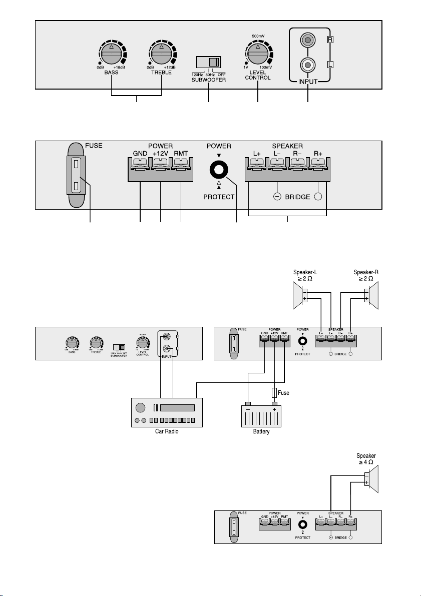
1 Übersicht der Bedienelemente und
Anschlüsse
1 2fach Klangreglung
2 Umschalter für Subwoofer-Betrieb mit wahlweiser
Trennfrequenz 80/120Hz
3 Regler zur Pegelanpassung
4 Line-Eingänge
5 Sicherung,
HPB-240/.. : 20 A
HPB-260/.. : 25 A
6 Masseanschluß
7 +12V-Versorgungsspannung
8 Steuereingang +12V zum Einschalten des
Boosters
9 Anzeige-LED,
grün: Betrieb
rot: die Schutzschaltung hat den Booster abge-
schaltet
10 Lautsprecheranschlüsse
2 Sicherheitshinweise
•
Beim Anschluß des Boosters an die Autobatterie ist
besondere Sorgfalt geboten. Bei Kurzschlüssen
können sehr gefährlich hohe Ströme fließen. Es ist
deshalb vor dem Anschluß die Plusklemme der
Autobatterie abzuschrauben.
•
Der Booster muß fest und fachgerecht an einer
mechanisch stabilen Stelle im Auto montiert werden, damit der Booster sich nicht löst und zu einem
gefährlichen Geschoß wird.
•
Während des Betriebs kann der Booster sehr heiß
werden. Darum keine hitzeempfindlichen Gegenstände in der Nähe plazieren, und während des
Betriebs den Booster nicht berühren.
•
Wird das Gerät zweckentfremdet, falsch bedient,
nicht richtig angeschlossen oder nicht fachgerecht
repariert, kann für eventuelle Schäden keine Haftung übernommen werden.
•
Für die Reinigung nur ein trockenes Staubtuch verwenden. Auf keinen Fall Chemikalien oder Wasser.
3 Vorsicht bei großen Lautstärken
•
Stellen Sie die Lautstärke nie sehr hoch ein. Extrem
hohe Lautstärken können das Gehör schädigen.
•
Das menschliche Ohr gewöhnt sich an große Lautstärken und empfindet sie nach einiger Zeit nicht
mehr so hoch. Darum eine einmal eingestellte hohe
Lautstärke nach der Gewöhnung nicht weiter
erhöhen.
•
Während des Autofahrens dürfen Signaltöne, von
z.B. einem Rettungswagen, nicht durch eine zu
große Lautstärke der Auto-Audioanlage übertönt
werden.
4 Montage
Bei der Auswahl des Montageplatzes sind die folgenden Punkte zu beachten:
•
Die Stromversorgungskabel von der Batterie zum
Booster sollten so kurz wie möglich sein. Es ist günstiger, längere Lautsprecherkabel zu verwenden
und dafür kürzere Stromversorgungskabel.
•
Um die entstehende Wärme des Boosters ableiten
zu können, muß eine ausreichende Belüftung
gewährleistet sein.
•
Wegen der beim Bremsen auftretenden Kräfte muß
der Booster an einer mechanisch stabilen Stelle
angeschraubt werden.
•
Die Sicherung und die Regler müssen zugänglich
sein.
Zur Montage die vier Bohrungen im Kühlkörper verwenden. Den Booster an geeigneter Stelle mit vier
Schrauben fest montieren.
5 Anschlüsse
Um Kurzschlüsse zu vermeiden, vor dem Anschluß
des Boosters die Plusklemme der Autobatterie ab-
schrauben.
Der gesamte Anschluß ist in Abb.3 dargestellt (bei der
Verwendung von zwei Lautsprechern). Abweichend
dazu zeigt Abb. 4 den Anschluß von einem Lautsprecher im Brückenbetrieb.
5.1 Stromversorgung
5.1.1 Anschluß RMT (8)
Der Booster wird durch eine +12 V-Steuerspannung
am Anschluß RMT ein- und ausgeschaltet. Den
Anschluß RMT mit dem +12 V-Ausgang vom Autoradio verbinden (Anschluß für eine Motorantenne,
eventuell mit der Motorantenne parallelschalten).
Wenn kein +12 V-Ausgang am Autoradio vorhanden ist, muß der Anschluß RMT zum Einschalten
+12 V über das Zündschloß oder über einen separaten Schalter erhalten.
5.1.2 Anschluß +12 V (7)
Den Anschluß +12V über ein entsprechend dickes
Kabel (siehe nächsten Absatz 5.1.3) mit der Plusklemme der Autobatterie verbinden. Um einen Kurzschluß durch die neu verlegte +12 V-Leitung abzusichern, muß eine Vorsicherung in unmittelbarer Nähe
der Batterie zwischengesetzt werden (Abb.3). Größe
der Sicherung:
HPB-240/.. : 20 A,
HPB-260/.. : 25 A.
5.1.3 Querschnitte der Stromversorgungskabel
Wichtig! Für den Querschnitt ist die Gesamt-
kabellänge vom +12V-Stromversorgungskabel plus
Massekabel maßgeblich!
D
A
CH
4
Page 5

empfohlener Kabelquerschnitt*
Gesamtkabellänge HPB-240/.. HPB-260/..
max. 14A max. 25A
2m 2mm
2
4mm
2
4m 4mm
2
7mm
2
6m 6mm
2
10mm
2
10m 10mm
2
20mm
2
*Bei den empfohlenen Kabelquerschnitten ergibt sich
ein maximaler Spannungsabfall von 0,25 V auf den
Stromversorgungskabeln. Werden geringere Querschnitte verwendet, erhöht sich der Spannungsabfall
und die Ausgangsleistung des Boosters verringert
sich.
Querschnitte für andere Kabellängen können nach der
folgenden Formel ausgerechnet werden:
Imax x (la + lb)
q =
15
q
= empfohlener Querschnitt in mm
2
Imax = max. Strombelastung in A
la = Kabellänge in m des +12V-Kabels
lb = Kabellänge in m des Massekabels
5.1.4 Anschluß GND (6)
Den Masseanschluß GND über ein entsprechend
dickes Kabel (gleicher Querschnitt wie das +12VStromversorgungskabel) mit der Masse des Autos
oder direkt mit der Minusklemme der Autobatterie verbinden. Zur Vermeidung von Masseschleifen muß die
Masse des Autoradios an die Stelle gelegt werden, wo
auch der Booster an Masse liegt.
5.2 Eingänge
Die beiden Booster-Eingänge (4) über Cinch-Kabel mit
den entsprechenden Line-Ausgängen am Autoradio
verbinden.
Sind am Autoradio keine Line-Ausgänge vorhanden, können die Lautsprecherausgänge des Autoradios über einen entsprechenden Übertrager (z.B.
MONACOR FGA-20) mit den Booster-Eingängen verbunden werden.
5.3 Lautsprecher
Die größte Ausgangsleistung wird beim Anschluß von
4Ω-Lautsprechern erreicht. Es können jedoch auch
8Ω-Lautsprecher angeschlossen werden, wobei sich
die Ausgangsleistung verringert. Alle Lautsprecher
müssen 2polig angeschlossen werden, d.h. ohne
gemeinsamen Masseanschluß!
Der genaue Anschluß richtet sich nach der Anzahl
der verwendeten Lautsprecher:
5.3.1 Zwei Lautsprecher (Abb. 3)
Die Belastbarkeit von jedem Lautsprecher muß mindestens 60 W Sinus (HPB-260/..) bzw. 40W Sinus
(HPB-240/..) betragen.
Anschlüsse der Lautsprecher an den Klemmen (10):
L+ = + linker Lautsprecher
L
-= -
linker Lautsprecher
R
-= -
rechter Lautsprecher
R+= + rechter Lautsprecher
Der Schiebeschalter SUBWOOFER (2) muß in Position OFF stehen.
5.3.2 Ein Lautsprecher (Abb. 4)
Beim Anschluß von einem Subwoofer kann die Aus-
gangsleistung verdoppelt werden. Für den Subwoofer
ist eine Frequenzweiche integriert, die mit dem Schalter SUBWOOFER (2) aktiviert wird. Die Belastbarkeit
des Subwoofers muß mindestens 120W Sinus (HPB260/..) bzw. 80W Sinus (HPB-240/..) betragen.
Anschlüsse des Subwoofers an den Klemmen (10):
L+ = bleibt frei
L
-= -
Subwoofer
R
-
= bleibt frei
R+= + Subwoofer
Der Schiebeschalter SUBWOOFER (2) muß in Posi-
tion 120Hz oder 80 Hz geschoben werden, entsprechend den Empfehlungen des Subwoofer-Herstellers.
Es ist die Frequenz einzustellen, bei der der Subwoofer zu arbeiten aufhört.
6 Pegel- und Klanganpassung
Vor dem Einschalten und der Pegel- und Klanganpassung sollte die komplette Verdrahtung des
Boosters noch einmal auf Richtigkeit überprüft werden. Erst danach die Plusklemme der Autobatterie
wieder anschließen.
Für eine optimale Pegelanpassung des Boosters an
das Autoradio dient der Regler LEVEL CONTROL (3).
Bei Bedarf können mit den beiden Klangreglern (1) die
Bässe um 18 dB und die Höhen um 12dB angehoben
werden.
7 Fehlerbeseitigung
Ist nach dem Einschalten der Auto-Audioanlage kein
Ton zu hören, kann der Fehler näher lokalisiert werden, indem zuerst die LED (9) des Boosters betrachtet
wird:
7.1 LED leuchtet nicht
1) Die Sicherung (5) am Booster und die Vorsicherung
an der Autobatterie überprüfen. Defekte Sicherungen auswechseln.
2) Das +12 V-Stromversorgungskabel sowie das Massekabel auf korrekten Anschluß und Unterbrechung kontrollieren.
3) Überprüfen, ob an der Anschlußklemme RMT (8)
des Boosters +12 V anliegt. Wenn nicht, die Leitung an der Klemme RMT entfernen und kurz die
Klemmen RMT (8) und +12 V (7) überbrücken.
Schaltet der Booster jetzt ein, liegt der Fehler in der
fehlenden Steuerspannung. Den +12V-Ausgang
des Autoradios (bzw. den separaten Schalter oder
das Zündschloß) und das entsprechende Anschlußkabel zum Booster überprüfen.
7.2 LED leuchtet grün, aber kein Ton
1) Lautsprecher, Lautsprecherleitungen und deren
korrekten Anschluß überprüfen. Besonders beim
Brückenbetrieb ist der richtige Lautsprecheranschluß äußerst wichtig.
D
A
CH
5
Page 6

2) Die Verbindungen an den Booster-Eingängen
überprüfen.
3) Autoradio-Ausgänge überprüfen.
7.3 LED leuchtet rot
Die LED zeigt einen Kurzschluß an den Booster-Ausgängen, eine Überlastung oder eine Überhitzung des
Boosters an. Die Schutzschaltung ist aktiviert. Zum
Deaktivieren der Schutzschaltung muß der Fehler behoben und der Booster min. 10Sekunden ausgeschaltet werden.
1) Lautsprecher und Lautsprecherleitungen auf Kurzschluß überprüfen.
2) Bei einer Überlastung Lautsprecherimpedanzen
überprüfen. Die Impedanz darf bei Brückenbetrieb
4Ω nicht unterschreiten und im 2-Kanalbetrieb
nicht 2Ω.
3) Bei einer Überhitzung den Booster abkühlen lassen und besser belüften.
8 Technische Daten
Frequenzbereich: . . . . . . . 10-30000 Hz
Ausgangsleistung max.
HPB-260/.. : . . . . . . . . . 2 x 120W
HPB-240/.. : . . . . . . . . . 2 x 80W
Ausgangsleistung Sinus
HPB-260/.. : . . . . . . . . . 2 x 60W
HPB-240/.. : . . . . . . . . . 2 x 40W
Ausgangsimpedanz: . . . . . 2 x 2Ω, bei Brücken-
betrieb 1 x 4Ω
Eingänge, 2 x Line: . . . . . . einstellbar
0,1
-
1V/10kΩ
Kanaltrennung: . . . . . . . . . > 50 dB
Störabstand: . . . . . . . . . . . > 80 dB
Klirrfaktor: . . . . . . . . . . . . . < 0,1 %
Stromversorgung: . . . . . . . 11
-
16V ,
25A max. (HPB-260/..),
14A max. (HPB-240/..),
Chassis Minus
Abmessungen (Bx H xT): . 240x56 x240 mm
Gewicht
HPB-260/.. : . . . . . . . . . 2,1kg
HPB-240/.. : . . . . . . . . . 1,5kg
Laut Angaben des Hersteller.
Änderungen vorbehalten.
D
A
CH
6
Page 7

Please unfold page 3. Then you can always see the
operating elements and connections described.
1 Operating Elements and Connections
1 Bass/treble controls
2 Selector switch for subwoofer operation with cross-
over frequency 80/120 Hz to be selected
3 Control for level matching
4 Line inputs
5 Fuse,
HPB-240/.. : 20 A
HPB-260/.. : 25 A
6 Ground terminal
7 +12V supply voltage
8 Control input +12V for switching on of the booster
9 LED display,
green: operation
red: the protection circuit has switched off the
booster
10 Speaker connections
2 Safety Notes
•
While connecting the booster to the car battery, be
especially careful. In case of short-circuits there
may be very dangerously high currents. Therefore
prior to the connection screw off the positive terminal of the car battery.
•
The booster must be mounted at a mechanically
rugged place in the car in a fixed and skilful manner,
so that it does not become loose and a dangerous
projectile.
•
While in operation the booster can get very hot.
Therefore do not place any objects near it which are
sensitive to heat and do not touch it while in operation.
•
If the booster is used for purposes other than originally intended, if it is operated, connected, or repaired in the wrong way, no liability can be taken over for
possible damage.
•
For cleaning only use a dry cloth for dust removal,
by no means chemicals or water.
3 Caution in Case of High Volumes
•
Never adjust the volume very high. Extremely high
volumes may damage the hearing.
•
A person’s hearing gets accustomed to high
volumes which after some time do not seem to be so
high. Therefore do not increase a high volume even
further after getting used to it.
•
While driving in a car the volume of the car audio
system must not be adjusted so high that the signal
sirens e. g. of an ambulance car cannot be heard
any more.
4 Mounting
While choosing the mounting place, watch the following items:
•
The power supply cable from the battery to the
booster should be as short as possible. It is better to
use longer speaker cables and shorter power supply
cables.
•
As the booster becomes very hot while in operation,
a sufficient ventilation must be provided.
•
As forces may occur while braking, the booster must
be screwed at a mechanically rugged place.
•
The fuses and controls must be accessible.
For mounting use the four drill holes in the heat sink.
Firmly mount the booster at a suitable place with
4 screws.
5 Connections
To prevent short-circuits, prior to the connection of
the booster screw off the positive terminal of the car
battery.
The complete construction is shown in fig.3 (two
speakers are used). Fig. 4 shows the connection of
one speaker in bridge operation.
5.1 Power Supply
5.1.1 Terminal RMT (8)
The booster is switched on and off by a +12V control
votage at the terminal RMT . Connect the terminal RMT
with the +12 V output of the radio (connection for a
motor antenna, if necessary to be connected in parallel with the motor antenna).
If there is no +12V output at the car radio, the terminal RMT must get +12 V for switching on via the
ignition key lock or a separate switch.
5.1.2 Terminal +12 V (7)
Connect the terminal +12 V via a cable of correspond-
ing cross section (see next para. 5.1.3) with the positive terminal of the car battery. To prevent a short-circuit by the newly laid +12 V cable, an additional fuse
must be inserted very close to the battery (fig. 3). Size
of the fuse:
HPB-240/.. : 20 A
HPB-260/.. : 25 A.
5.1.3 Cross sections of the power supply cables
Important! For the cross sections the total cable
length of the +12 V power supply cable plus ground
cable is decisive!
Recommended cable cross section*
Total cable length HPB-240/.. HPB-260/..
max. 14A max. 25A
2m 2mm
2
4mm
2
4m 4mm
2
7mm
2
6m 6mm
2
10mm
2
10m 10mm
2
20mm
2
*With the recommended cable cross sections there is
a max. voltage drop of 0.25 V in the power supply
cables. If minor cross sections are used, the voltage
GB
7
Page 8

GB8drop is increasing and the output power of the booster
is reducing.
The cross sections for other cable lengths can be cal-
culated according to the following formula:
Imax x (la + lb)
q =
15
q
= recommended cross section in mm
2
Imax = max. current load in A
la = cable length in m of the +12V cable
lb = cable length in m of the ground cable
5.1.4 Terminal GND (6)
Connect the ground terminal GND via a cable of cor-
responding cross section (same cross section as the
+12V power supply cable) with the ground of the car
or directly with the negative terminal of the car battery.
To avoid ground loops, the ground of the car radio
must be placed at the point where also the booster is
grounded.
5.2 Inputs
Connect both booster inputs (4) via cinch cables with
the corresponding line outputs at the car radio.
If there are no line outputs at the car radio, the
speaker outputs of the car radio can be connected via
a corresponding transformer (e. g. MONACOR FGA-
20) with the booster inputs.
5.3 Speakers
The greatest output power is obtained with the
connection of 4Ω speakers. Also 8 Ωspeakers may be
connected but in this case the output power is reduced. All speakers must be connected with 2 poles, i. e.
without common ground connection!
The exact connection depends on the number of
the speakers used!
5.3.1 Two speakers (fig. 3)
The capability of each speaker must at least be
60Wrms (HPB-260/..) resp. 40W rms (HPB-240/..).
Connections of the speakers at the terminals (10):
L+ = + left speaker
L
-
= -left speaker
R
-= -
right speaker
R+= + right speaker
The sliding switch SUBWOOFER (2) must be in posi-
tion OFF.
5.3.2 One speaker (fig. 4)
With the connection of one subwoofer the output
power can be doubled. For the subwoofer a crossover
system has been integrated which is activated with the
switch SUBWOOFER (2). The capability of the subwoofer must at least be 120Wrms (HPB-260/..) resp.
80Wrms (HPB-240/..).
Connections of the subwoofer at the terminals (10):
L+ = remains unconnected
L
-= -
subwoofer
R
-
= remains unconnected
R+= + subwoofer
The sliding switch SUBWOOFER (2) must be in position 120Hz or 80Hz, according to the recommendations of the subwoofer manufacturer. Adjust the frequency at which the subwoofer stops working.
6 Level and Sound Matching
Prior to switching on the level and sound matching,
the complete wiring of the booster should be
checked once again. Only then connect the positive
terminal of the car battery again.
For an optimum level matching of the booster to the
car radio the control LEVELCONTROL (3) is provided.
If required, with the BASS/ TREBLE controls (1) the
low frequencies can be boosted by 18dB and the high
frequencies by 12dB.
7 Trouble Shooting
If no sound can be heard after switching on the car
audio system, it is easier to locate the fault while
watching the LED (9) of the booster at first:
7.1 LED does not light
1) Check the fuse (5) at the booster and the additional
fuse at the car battery. Replace defective fuses.
2) Control the +12 V power supply cable as well as the
ground cable for correct connection and for interruption.
3) Check if there is +12 V at the terminal RMT (8) of
the booster. If not, remove the cable at the terminal
RMT and shortly bridge the terminals RMT (8) and
+12V (7). If the booster now switches on, the error
is due to the missing control voltage. Check the
+12 V output of the car radio (resp. the separate
switch or the ignition key lock) and the corresponding connection cable to the booster.
7.2 LED shows a green light, but there is no sound
1) Check speakers, speaker cables, and their correct
connection. Especially with bridge operation the
correct speaker connection is very important.
2) Check the connections at the booster inputs.
3) Check the car radio outputs.
7.3 LED shows a red light
The LED shows a short-circuit at the booster outputs,
an overload, or an overheating of the booster. The protection circuit is activated. For deactivating the protection circuit the error must be removed and the booster
must be switched off for at least 10 seconds.
1) Check speakers and speaker cables for short-cir-
cuit.
2) In case of an overload check the speaker imped-
ances. The impedance must not be below 4Ω with
bridge operation and not below 2Ω with 2-channel
operation.
3) In case of an overheating let the booster cool down
and improve the ventilation.
Page 9

8 Specifications
Frequency range: . . . . . . . 10-30000 Hz
Output power max.
HPB-260/.. : . . . . . . . . . 2 x 120W
HPB-240/.. : . . . . . . . . . 2 x 80W
Output power rms
HPB-260/.. : . . . . . . . . . 2 x 60W
HPB-240/.. : . . . . . . . . . 2 x 40W
Output impedance: . . . . . . 2 x 2 Ω, with bridge
operation 1 x 4Ω
Inputs, 2 x line: . . . . . . . . . adjustable
0.1
-
1V/10kΩ
Channel separation: . . . . . > 50dB
S/N ratio: . . . . . . . . . . . . . > 80 dB
THD: . . . . . . . . . . . . . . . . . < 0.1 %
Power supply: . . . . . . . . . . 11
-
16V
25A max. (HPB-260/..),
14A max. (HPB-240/..),
Chassis Minus
Dimensions (Wx H xD): . . 240 x 56 x 240 mm
Weight
HPB-260/.. : . . . . . . . . . 2.1kg
HPB-240/.. : . . . . . . . . . 1.5kg
According to the manufacturer.
Subject to technical change.
GB
9
Page 10

Ouvrez le présent livret page 3 de manière à visualiser les éléments et branchements
1 Eléments et branchements
1 Réglage graves/aigus
2 Inverseur pour passer en mode subwoofer, fré-
quence de coupure au choix: 80/120Hz
3 Potentiomètre rotatif, réglage de niveau
4 Entrées Line
5 Fusible
HPB-240/.. : 20 A
HPB-260/.. : 25 A
6 Branchement masse
7 Tension d’alimentation +12V
8 Entrée +12 V pour allumer l’ampli
9 Diode d’affichage
vert: en fonctionnement
rouge: le circuit de protection a coupé l’alimenta-
tion de l’ampli
10 Bornes des haut-parleurs
2 Conseils - Sécurité
•
Soyez très prudent lorsque vous reliez l’amplificateur à la batterie de la voiture. En cas de court-circuits, des courants très élevés et dangereux circulent. Il convient donc de dévisser, avant tout
branchement, la borne PLUS de la batterie de la voiture.
•
L’ampli doit être solidement fixé dans un endroit
mécaniquement stable de la voiture. Il ne doit pas
se désolidariser de son support et devenir un projectile dangereux.
•
Lors du fonctionnement, l’ampli devient très chaud.
C’est pourquoi il ne faut pas placer d’objets sensibles à la chaleur à proximité et éviter tout contact
avec l’ampli lors de son utilisation.
•
Nous déclinons toute responsabilité si l’appareil est
utilisé dans un autre but que celui pour lequel il a été
construit, s’il est mal utilisé, si les branchements
sont incorrects ou si des réparations sont effectuées
par toute personne non qualifiée.
•
Utilisez un chiffon doux sec pour nettoyer l’appareil,
en aucun cas, d’eau ou de produits chimiques
3 Attention en cas de volumes élevés
•
Ne réglez pas le volume de l’ampli trop fort. Des
volumes extrêmement élevés peuvent entraîner des
troubles de l’audition.
•
L’oreille humaine s’habitue aux volumes élevés et,
après une période d’accoutumance, ne les perçoit
pas aussi forts. C’est pourquoi il ne faut pas augmenter un volume auquel l’oreille s’est déjà habituée.
•
Lorsque vous conduisez, le niveau sonore de votre
installation audio ne doit pas vous empêcher d’entendre certains signaux sonores comme une ambulance...
4 Montage
Lorsque vous choisissez le lieu d’installation de votre
ampli, respectez les points suivants :
•
Les câbles d’alimentation allant de la batterie à l’ampli doivent être aussi courts que possible. Il est
préférable d’utiliser des câbles haut-parleurs plus
longs et des câbles d’alimentation plus courts.
•
Assurez-vous que l’endroit d’installation est correctement ventilé de manière à pouvoir évacuer facilement la chaleur dégagée par l’ampli.
•
L’ampli doit être fixé à un endroit mécaniquement
stable de manière à contrer les forces créées lorsque vous freinez.
•
Le fusible et les divers réglages doivent être acces-
sibles.
Pour effectuer le montage, utilisez les 4 trous de
perçage dans le radiateur. Fixez l’ampli à l’endroit
voulu avec les 4 vis.
5 Branchements
Pour éviter tout court-circuit, dévissez la borne
PLUS de la batterie de la voiture avant d’effectuer
tout branchement.
Le schéma 3 indique le branchement complet (en utilisant deux haut-parleurs). Le schéma 4 indique le
branchement d’un seul haut-parleur mais en mode
bridgé.
5.1 Alimentation
5.1.1 Borne RMT (8)
L’ampli est allumé et éteint par une tension +12V à la
borne RMT. Reliez cette borne RMT à la sortie +12 V
de l’auto-radio (branchement pour une antenne de
voiture, éventuellement branchement en parallèle
avec l’antenne).
Si l’auto-radio n’est pas équipé d’une sortie +12V,
il faut relier la borne RMT à la clé de contact ou à un
interrupteur séparé.
5.1.2 Borne +12V (7)
Reliez la borne + 12 V au pôle PLUS de la batterie de
la voiture avec un câble adéquat (voir paragraphe
5.1.3). Pour éviter tout court-circuit dû au nouveau
câble +12V, il faut insérer très près de la batterie un
fusible supplémentaire (schéma 3).
Dimensions des fusibles:
HPB-240/.. : 20 A
HPB-260/.. : 25 A
5.1.3 Section des câbles d’alimentation
ATTENTION! Pour la section, la longueur totale du
câble d’alimentation +12V plus le câble de masse est
déterminante.
F
B
CH
10
Page 11

section du câble recommandée*
longueur totale HPB-240/.. HPB-260/..
du câble max. 14A max. 25A
2m 2mm
2
4mm
2
4m 4mm
2
7mm
2
6m 6mm
2
10mm
2
10m 10mm
2
20mm
2
*Avec les sections recommandées, il y a une baisse
maximale de tension de 0,25 V sur les câbles d’alimentation. Si on utilise des sections plus petites, cette
baisse s’accentue et la puissance de sortie de l’ampli
diminue.
Les sections pour les autres longueurs de câbles se
calculent d’après la formule suivante :
Imax x (la + lb)
q =
15
q
= section recommandée en mm
2
Imax = intensité maximale en A
la = longueur de câble en m du câble +12V
lb = longueur de câble en m du câble de masse
5.1.4 Borne GND (6)
Reliez la borne GND (masse) à la masse de la voiture
avec un câble adéquat (même section que le câble
d’alimentation +12V) ou directement à la borne
MOINS de la batterie. Pour éviter tout bouclage de
masse, la masse de l’auto-radio doit être à l’endroit où
est celle de l’ampli.
5.2 Entrées
Les deux entrées de l’ampli (4) doivent être reliées
aux sorties LINE correspondantes de l’auto-radio avec
un câble RCA.
Si l’auto-radio n’est pas équipé de sorties LINE, on
peut utiliser les sorties haut-parleurs de l’auto-radio et
les relier aux entrées de l’ampli avec un transformateur (par exemple FGA-20).
5.3 Haut-parleurs
On atteint la puissance maximale de sortie lorsqu’on
branche des haut-parleurs 4Ω. Il est cependant possible de brancher des haut-parleurs 8 Ω, mais la puissance de sortie est moindre. Tous les haut-parleurs
doivent être reliés avec deux pôles, sans branche-
ment commun à la masse.
Le branchement correct dépend du nombre de
haut-parleurs utilisés.
5.3.1 Deux haut-parleurs (schéma 3)
La puissance admissible de chaque haut-parleur doit
être de 60W RMS au moins pour le HPB-260/.. et de
40 W RMS au moins pour le HPB-240/...
Branchements des HP aux bornes (10):
L+ = +HP gauche
L
-= -
HP gauche
R
-= -
HP droit
R+= + HP droit
L’inverseur SUBWOOFER (2) doit être sur la position
OFF.
5.3.2 Un seul haut-parleur (schéma 4)
Lorsque vous branchez un subwoofer, la puissance de
sortie peut être doublée. Pour le subwoofer, un filtre
est intégré ; on le met en marche avec l’inverseur
SUBWOOFER (2). La puissance admissible du subwoofer doit être de 120W RMS pour le HPB-260 et de
80W RMS pour le HPB-240.
Branchements du subwoofer aux bornes (10) :
L+ = reste libre
L- = - subwoofer
R- = reste libre
R+= + subwoofer
L’inverseur SUBWOOFER (2) doit être sur la position
120Hz ou 80Hz, selon les conseils du fabricant du
subwoofer. Il faut régler la fréquence pour laquelle le
subwoofer cesse de travailler.
6 Réglages de niveaux
Avant d’allumer votre ampli et d’effectuer les réglages de niveaux,il convient de vérifier attentivement
l’ensemble des câblages. Une fois cette opération
terminée, vous pouvez rebrancher la borne PLUS
de la batterie de la voiture.
Pour réaliser une adaptation optimale des niveaux de
l’ampli à l’auto-radio, utilisez le potentiomètre LEVEL
CONTROL (3). Si besoin est, il est possible d’augmenter les graves de 18dB et les aigus de 12 dB avec
les potentiomètres (1).
7 Erreurs possibles
Si lorsque vous allumez l’auto-radio, il n’y a aucun
son, vous pouvez localiser le problème en vérifiant la
diode (9) de l’ampli:
7.1 La diode ne s’allume pas:
1) Vérifiez le fusible (5) de l’ampli et le fusible supplémentaire de la batterie de la voiture. Remplacez les
fusibles défectueux.
2) Contrôlez si le câble d’alimentation +12 V et le
câble de masse se sont pas abîmés et si leurs
branchements sont corrects.
3) Vérifiez si une tension +12 V est bien à la borne
RMT (8) de l’ampli. Si ce n’est pas le cas, retirez le
câble de la borne RMT et bridgez les bornes RMT
(8) avec la tension +12V (7). Si l’ampli s’allume, il
manque de la tension. Vérifiez alors la sortie +12V
de l’auto-radio (ou l’interrupteur annexe ou la clé de
contact) et le câble de connexion allant à l’ampli.
7.2 La diode est verte mais il n’y a pas de son
1) Vérifiez les haut-parleurs, leurs câbles et branchements. Le câblage des haut-parleurs en cas d’utilisation en mode bridgé est essentiel.
2) Vérifiez les liaisons aux entrées de l’ampli.
3) Vérifiez les sorties de l’auto-radio.
F
B
CH
11
Page 12

7.3 La diode est rouge
La diode indique un court-circuit aux sorties de l’ampli,
une surcharge ou une surchauffe de l’ampli. Le circuit
de protection est activé. Pour le désactiver, il faut
résoudre le problème et couper l’ampli pendant
10 secondes au moins.
1) Recherchez sur le haut-parleur et les câbles de
haut-parleurs un éventuel court-circuit.
2) En cas de surcharge, vérifiez les impédances des
haut-parleurs. En mode bridgé, l’impédance ne doit
pas être inférieure à 4Ω, en mode 2 canaux, à 2Ω.
3) En cas de surchauffe, laissez refroidir l’ampli et
cherchez à améliorer la ventilation.
8 Caractéristiques techniques
Bande passante: . . . . . . . . 10
-
30000 Hz
Puissance de sortie max.
HPB-260/..: . . . . . . . . . . 2 x 120W
HPB-240/..: . . . . . . . . . . 2 x 80W
Puissance de sortie RMS
HPB-260/.. : . . . . . . . . . 2 x 60W
HPB-240/.. : . . . . . . . . . 2 x 40 W
Impédance de sortie: . . . . 2 x 2Ω,
1 x 4Ω en mode bridgé
Entrées 2 x LINE: . . . . . . . réglable
0,1
-
1V/10kΩ
Séparation des canaux: . . > 50dB
Rapport signal/bruit: . . . . . > 80dB
Taux de distorsion: . . . . . . <0,1%
Alimentation: . . . . . . . . . . . 11
-
16V
25A max. (HPB-260/..),
14A max. (HPB-240/..),
moins au châssis
Dimensions (LxHxP): . . . . 240 x 56 x 240 mm
Poids
HPB-260: . . . . . . . . . . . 2,1kg
HPB-240: . . . . . . . . . . . 1,5kg
D’après les données du constructeur.
tout droit de modification réservé.
F
B
CH
12
Page 13

Vi preghiamo di aprire completamente la pagina 3.
Così vedrete sempre gli elementi di comando e i
collegamenti descritti.
1 Elementi di comando e collegamenti
1 Regolazione doppia del suono
2 Commutatore per funzionamento subwoofer con
frequenza di taglio a scelta 80/120 Hz
3 Regolatore per adattamento livello
4 Ingressi Line
5 Fusibili:
HPB-240/.. : 20 A
HPB-260/.. : 25 A
6 Massa
7 Tensione di alimentazione +12V
8 Ingresso comando +12V per l’accensione del boo-
ster
9 Spia a LED
verde: funzionamento
rosso: il circuito di protezione ha disinserito
il booster
10 Collegamenti degli altoparlanti
2 Avvisi di sicurezza
•
Usare particolare cura nel collegamento con la batteria dell’auto. Nel caso di cortocircuiti ci possono
essere delle correnti molto alte. Prima del collegamento scollegare il polo positivo della batteria.
•
Prevedere un posto solido e montare il booster con
cura per evitare che si possa staccare, diventando
pericoloso in caso di incidente.
•
Durante il funzionamento, il booster può riscaldarsi
molto. Non mettere nelle sue vicinanze oggetti sensibili al calore e non toccare il booster.
•
Nel caso di uso improprio, di collegamenti sbagliati
o di riparazione scorretta non si assume nessuna
responsabilità per eventuali danni.
•
Per la pulizia usare solo un panno asciutto; non
impiegare in nessun caso prodotti chimici o acqua.
3 Attenzione col volume alto
•
Non alzare troppo il volume. Il volume troppo alto
può danneggiare l’udito.
•
L’orecchio si abitua al volume alto e dopo un certo
periodo non se ne accorge più. Pertanto conviene
non aumentare il volume alto impostato inizialmente.
•
Mentre si guida, i segnali di ambulanze ecc. non
devono essere coperti dal volume dell’impianto
audio.
4 Montaggio
Prima di scegliere un posto per il montaggio occorre
considerare i seguenti punti.
•
I cavi di alimentazione dalla batteria al booster
devono essere possibilmente corti. E’ preferibile
usare lunghi cavi per gli altoparlanti e tenere corti di
cavi di alimentazione.
I
13
•
Per poter dissipare il calore sprigionato dal booster
deve essere garantita una ventilazione sufficiente.
•
Per le forze che si manifestano nelle frenate, il
punto di montaggio deve essere meccanicamente
stabile.
•
Il fusibile e i regolatori devono essere accessibili.
Per il montaggio usare i quattro fori nel dissipatore.
Montare il booster saldamente usando quattro viti.
5 Collegamenti
Per evitare cortocircuiti, prima del montaggio scolle-
gare il polo positivo della batteria auto.
La figura 3 illustra il collegamento (nel caso di due
altoparlanti). La figura 4 illustra il collegamento di un
altoparlante con funzionamento a ponte.
5.1 Alimentazione corrente
5.1.1 Collegamento RMT (8)
Il booster viene acceso e spento da una tensione di
comando +12V tramite l’ingresso RMT. Collegare
RMT con l’uscita +12 V dell’autoradio (collegamento
per un’antenna motorizzata; eventualmente collegamento in parallelo con tale antenna).
Se l’autoradio non presenta nessun’uscita +12V,
collegare l’ingresso RMT con l’accensione della
macchina o con un interruttore separato.
5.1.2 Collegamento +12V (7)
Collegare l’ingresso +12V con il polo positivo della
batteria auto impiegando un cavo sufficientemente
grosso (vedere 5.1.3). Per proteggere il nuovo cavo
+12V inserire un fusibile nella diretta vicinanza della
batteria (fig. 3). Potenza dei fusibili: HPB-240/.. : 20 A,
HPB-260/.. : 25 A.
5.1.3 Sezione del cavo di alimentazione
Importante! La sezione dipende dalla lunghezza globale del cavo, dal cavo alimentazione +12V più cavo
di massa!
Lunghezza Sezione consigliata*
totale cavo HPB-240/.. HPB-260/..
max. 14A max. 25A
2m 2mm
2
4mm
2
4m 4mm
2
7mm
2
6m 6mm
2
10mm
2
10m 10mm
2
20mm
2
*Le sezioni consigliate comportano una perdita di tensione massima di 0,25 V lungo il cavo di alimentazione. Se si impiegano sezioni minori, la perdita di tensione aumenta e la potenza di uscita del booster viene
ridotta.
Le sezioni per la lunghezza del cavo si calcolano
come segue:
Imax x (la + lb)
q =
15
q
= sezione consigliata in mm
2
Imax = carico massima di corrente in A
la = lunghezza cavo +12V in m
lb = lunghezza cavo massa in m
Page 14

5.1.4 Collegamento GROUND (6)
Collegare l’ingresso GROUND con la massa dell’auto
o direttamente con il polo negativo della batteria,
usando un cavo sufficientemente grosso (come per
l’alimentazione +12V). Per evitare l’effetto di anelli di
terra, la massa dell’autoradio deve essere collegata
allo stesso punto in cui è collegata la massa del booster.
5.2 Ingressi
Collegare i due ingressi (4) del booster con le uscite
Line dell’autoradio usando cavi cinch.
Se l’autoradio non possiede nessun’uscita Line, le
uscite per gli altoparlanti possono essere collegate
con gli ingressi del booster mediante un trasformatore
(p. e. MONACOR FGA-20).
5.3 Altoparlanti
La massima potenza di uscita si raggiunge con altoparlanti a 4Ω. Si possono collegare anche altoparlanti
a 8 Ω; in tal caso, la potenza di uscita è ridotta. Tutti gli
altoparlanti devono essere collegati a due poli, cioè
senza massa comune!
Il collegamento esatto dipende dal numero degli
altoparlanti:
5.3.1 Due altoparlanti (fig. 3)
La potenza efficace di ogni altoparlante deve essere
per lo meno di 60W (per HPB-260 /..) e di 40 W (per
HPB-240/..).
Collegamento degli altoparlanti ai morsetti (10):
L+ = +sinistra
L
-
= -sinistra
R-= -destra
R+= + destra
Il commutatore SUBWOOFER (2) deve essere in
posizione OFF.
5.3.2 Un altoparlante (fig. 4)
Collegando un subwoofer, la potenza d’uscita può
essere raddoppiata. Per il subwoofer è integrato un filtro di frequenze che viene attivato con il commutatore
SUBWOOFER (2). Il subwoofer deve avere una
potenza efficace per lo meno di 120 W (per HPB260/..) e di 80 W (per HPB-240/..).
Collegamento del subwoofer ai morsetti (10):
L+ = libero
L
-= -
subwoofer
R-= libero
R+= + subwoofer
l commutatore SUBWOOFER (2) deve trovarsi in
posizione 120 Hz oppure 80 Hz, a seconda delle indicazioni del produttore del subwoofer. Si imposta
quella frequenza in cui il subwoofer smette di funzionare.
6 Adattamento livello e suono
Prima dell’accensione e dell’adattamento del livello
e del suono controllare l’intero cablaggio del booster. Quindi ricollegare il polo positivo della batteria
auto.
Per un adattamento ottimale del livello del booster all’autoradio si usano i due regolatori LEVEL CONTROL
(3). I due regolatori del suono (1) servono per alzare i
bassi di 18dB e gli acuti di 12 dB.
7 Eliminazione di difetti
Se dopo l’accensione dell’impianto audio dell’automobile non si sente niente, si può localizzare il difetto
osservando il LED (9) sul booster:
7.1 Il LED non si accende
1) Controllare il fusibile (5) sul booster e quello vicino
alla batteria dell’auto e sostituirlo se difettoso.
2) Controllare il cavo di alimentazione +12 V nonché il
cavo di massa. I collegamenti devono essere corretti e non ci deve essere nessuna interruzione.
3) Verificare se al morsetto RMT (8) del booster è presente una tensione di +12V. In caso negativo, staccare il cavo dal morsetto RMT e ponticellare brevemente i morsetti RMT (8) e +12V (7). Se il booster
si accende ora, significa che manca la tensione di
comando. Controllare l’uscita +12 V dell’autoradio
(oppure l’interruttore separato o l’accensione della
macchina) nonché il cavo di collegamento verso il
booster.
7.2 Il LED verde si accende, ma non si sente niente
1) Controllare l’altoparlante, i cavi degli altoparlanti e i
relativi collegamenti. Nel caso di funzionamento a
ponte, il corretto collegamento degli altoparlanti è di
estrema importanza.
2) Controllare i collegamenti agli ingressi del booster.
3) Controllare le uscite dell’autoradio.
7.3 Il LED rosso si accende
Il LED indica un cortocircuito alle uscite del booster, un
sovraccarico o un surriscaldamento del booster. Il circuito di protezione è attivato. Per disattivare il circuito
di protezione, eliminare prima il difetto e lasciare
spento il booster per un minimo di 10 secondi.
1) Controllare se ci sono cortocircuiti negli altoparlanti
e nei loro cavi.
2) Nel caso di sovraccarico controllare le impedenze
degli altoparlanti. L’impedenza massima nel funzionamento a ponte è di 4Ω, e nel funzionamento a 2
canali di 2Ω.
3) Nel caso di surriscaldamento far raffreddare il booster e migliorare la ventilazione.
I
14
Page 15

8 Dati tecnici
Banda passante: . . . . . . . . 10-30000 Hz
Potenza d’uscita max.
HPB-260/.. . . . . . . . . . . 2 x 120W
HPB-240/.. . . . . . . . . . . 2 x 80W
Potenza efficace
HPB-260/.. . . . . . . . . . . 2 x 60W
HPB-240/.. . . . . . . . . . . 2 x 40W
Impedenza d’uscita: . . . . . 2 x 2 Ω, funzionamento
a ponte
1 x 4Ω
Ingressi, 2 x Line: . . . . . . . regolabili 0,1
-
1V/10 kΩ
Separazione canali: . . . . . >50dB
Rapporto S/R: . . . . . . . . . . >80dB
Fattore di distorsione: . . . . <0,1 %
Alimentazione: . . . . . . . . . 11
-
16V ,
25 A max. (HPB-260/..),
14 A max. (HPB-240/..),
neg. sul telaio
Dimensioni (lx hxp): . . . . . 240 x 56 x 240mm
Peso
HPB-260/.. . . . . . . . . . . 2,1kg
HPB-240/.. . . . . . . . . . . 1,5kg
Dati forniti dal costruttore.
Con riserva di modifiche tecniche.
I
15
Page 16

Vouw bladzijde 3 helemaal open, zodat u een overzicht hebt van de bedieningselementen en de
aansluitingen.
1 Bedieningselementen en
aansluitingen
1 BASS/TREBLE-regelaars
2 Keuzeschakelaar waarmee men bij gebruik van
een subwoofer de kantelfrequentie van het filter
kan instellen op 80 of 120Hz.
3 Regelaars om het volume aan te passen
4 Lijningangen
5 Zekering:
HPB-240/.. : 20 A
HPB-260/.. : 25 A
6 Massaklem
7 +12 V-klem
8 Controle-ingang +12 V om de booster in te scha-
kelen.
9 LED-display,
Groene LED: Het toestel is in werking.
Rode LED: Het beveiligingscircuit heeft
de booster uitgeschakeld.
10 Luidsprekerklemmen
2 Veiligheidsvoorschriften
•
De aansluiting van de booster op de autobatterij
dient zorgvuldig te gebeuren. In geval van kortsluiting kunnen er gevaarlijk grote stromen ontstaan.
Daarom is het nuttig voor de aansluiting van de booster de positieve klem los te maken van de autobatterij.
•
De booster moet op een mechanisch stabiele plaats
in de auto gemonteerd worden, zodat hij niet kan
loskomen en op die manier een gevaarlijk projectiel
gaat vormen.
•
Tijdens de werking kan de versterker zeer warm
worden. Plaats daarom geen objecten in de buurt
die gevoelig zijn voor warmte. Raak een werkend
toestel niet aan.
•
In geval van ongeoorloofd of verkeerd gebruik of
van herstelling door een niet-gekwalificeerd persoon vervalt de garantie bij eventuele schade.
•
Verwijder het stof met een droge doek. Gebruik
zeker geen chemicaliën of water.
3 Opgelet bij gebruik van hoge
vermogens
•
Vermijd te hoge volumes. Uitzonderlijk hoge volumes kunnen het gehoor beschadigen.
•
Het gehoor raakt gewend aan hoge volumes, die na
een tijdje niet meer zo hoog worden ervaren. Draai
daarom het volume niet verder open zelfs nadat
men het gewend is.
•
Zorg ervoor dat het geluidsvolume van het audiosysteem in de auto niet te hoog staat, waardoor
andere geluidssignalen, bijvoorbeeld die van een
ambulance, niet meer hoorbaar zouden zijn.
4 Montage
Let op de volgende elementen bij de keuze van een
montageplaats:
•
De voedingskabels van de batterij naar de booster
moeten zo kort mogelijk zijn. Het is beter langere
luidsprekerkabels en kortere voedingskabels te
gebruiken.
•
Zorg voor een goede ventilatie aangezien de booster gedurende de werking opwarmt.
•
Door het grote gewicht van de booster moet deze op
een mechanisch stabiele plaats vastgeschroefd
worden.
•
De zekeringen moeten voor vervanging toegankelijk
blijven.
Gebruik voor montage de 4 openingen van de koelplaat. Monteer de booster met 4 schroeven op een
geschikte plaats.
5 Aansluitingen
Om kortsluitingen te vermijden is het nuttig om voor
de aansluiting van de booster, de positieve klem los
te maken van de autobatterij.
De volledige aansluiting wordt getoond in fig.3 (met 2
luidsprekers). Figuur 4 toont de aansluiting van één
luidspreker met de booster bruggeschakeld.
5.1 Voedingspanning
5.1.1. RMT-aansluiting (8)
De booster wordt in- en uitgeschakeld door een
+12V
–
spanning aan de RMT-aansluiting. Verbind de
RMT-aansluiting met de +12V–uitgang van de autoradio (aansluiting voor een antennemotor, parallelschakeling met een dergelijke antenne is mogelijk).
Is er geen +12 V
–
uitgang aan de autoradio, dan
moet de RMT-aansluiting een +12 V–verbinding krijgen via het startcontact of een aparte schakelaar.
5.1.2. +12 V–aansluiting (7)
Verbind de + 12 V
–
aansluiting via een kabel, met de
juiste doorsnede (zie paragraaf 5.1.3.), met de positieve klem van de autobatterij. Om bij de nieuwe
+12V
–
kabel een kortsluiting te vermijden, moet een
extra zekering nabij de batterij geplaatst worden
(figuur 3).
Grootte van de zekering:
HPB-240/.. : 20 A
HPB-260/.. : 25 A
5.1.3. Doorsnede van de voedingskabels:
Belangrijk! Voor de doorsnede van de kabel is de
lengte van de +12 V
–
kabel en de massageleider bepa-
lend.
NL
B
16
Page 17

Aanbevolen kabeldoorsnede*
Totale kabellengte HPB-240/.. HPB-260/..
max. 14A max. 25A
2m 2mm
2
4mm
2
4m 4mm
2
7mm
2
6m 6mm
2
10mm
2
10m 10mm
2
20mm
2
*Bij de aanbevolen doorsnede is er een maximale
spanningsval van 0,25V in de voedingskabels. Indien
een kleinere doorsnede gebruikt wordt, dan stijgt de
spanningsval en vermindert het uitgangsvermogen.
De doorsnede van de kabels kan berekend worden
met de volgende formule:
Imax x (la + lb)
q =
15
q
= aanbevolen doorsnede in mm
2
Imax = maximale stroom in A
la = lengte van de +12V-kabel in m
lb = lengte van de massageleider in m
5.1.4. Aansluiting GND (6)
Verbind de GND-aansluiting via een kabel met een
geschikte doorsnede (zelfde doorsnede als de
+12V
–
kabel) met de massa van de auto of rechtstreeks met de negatieve pool van de autobatterij. Om
aardlussen te vermijden moeten de massaverbindingen van de autoradio en de booster op dezelfde plaats
liggen.
5.2 Ingangen
Verbind de beide ingangen (4) van de booster via
cinch-kabels met de overeenkomstige lijnuitgangen
van de autoradio.
Indien de radio geen lijnuitgangen heeft, dan moeten de luidsprekeruitgangen van de autoradio via een
geschikte transformator (bv. de MONACOR FGA-20)
met de ingangen van de booster verbonden worden.
5.3 Luidsprekers
Het maximale uitgangsvermogen verkrijgt men bij
aansluiting van 4Ω-Luidsprekers. Maar men kan ook
8Ω-Luidsprekers gebruiken waarbij het uitgangsvermogen wordt gereduceerd. Alle luidsprekers moeten
een dubbelpolige aansluiting hebben met de booster,
d.w.z. zonder gemeenschappelijke massa!
De juiste aansluiting van de luidsprekers hangt af
van het aantal gebruikte luidsprekers!
5.3.1. Twee luidsprekers (figuur 3)
Het vermogen van elke luidspreker moet minstens 60
Wrms (HPB-260/..) resp. 40 Wrms (HPB-240/..) zijn.
Aansluiting van de frontluidsprekers op de klemmen
(10):
L+ = + linker luidspreker, vooraan
L
-= -
linker luidspreker, vooraan
R
-= -
rechter luidspreker, vooraan
R+= + rechter luidspreker, vooraan
De keuzeschakelaar SUBWOOFER (2) moet in de
OFF-stand staan.
5.3.2 Eén luidspreker (figuur 4)
Met de aansluiting van een subwoofer kan het uit-
gangsvermogen verdubbeld worden. Voor de subwoofer is een crossover-netwerk geïntegreerd. Deze
schakeling wordt geactiveerd met de SUBWOOFERschakelaar (2). De subwoofer moet een vermogen van
minstens 120 Wrms (HPB-260/..) respectievelijk 80
Wrms (HPB-240/..) kunnen verwerken.
Aansluiting van de subwoofer op de klemmen (10):
L+ = niet aangesloten
L
-= -
subwoofer
R-= niet aangesloten
R+= + subwoofer
De schuifschakelaar SUBWOOFER (2) moet in de
stand 120 Hz of 80Hz geplaatst worden. Deze instelling is afhankelijk van de subwoofer. Kies de frequentie waarop de subwoofer optimaal werkt.
6 Aanpassing van volume en klank
Alvorens in te schakelen en het geluidsniveau aan
te passen, moet de volledige aansluiting van de
booster nogmaals gecontroleerd worden. Verbind
pas nadien de positieve klem opnieuw met de auto-
batterij.
Voor een optimale aanpassing van het niveau van de
booster op het niveau van de autoradio is een LEVEL
CONTROL-regelaar (3) voorzien. Met de BASS/
TREBLE-regelaars (1) kunnen de lage frequenties
met 18 dB versterkt worden en de hoge frequenties
met 12dB.
7 Fout opsporing
Indien er geen klank is na het inschakelen van het
autoradiosysteem, dan kan de fout precies gelocaliseerd worden door in de eerste plaats op de LED (9)
van de booster te letten.
7.1 De LED licht niet op
1) Controleer de zekering (5) van de booster en de
extra zekering aan de autobatterij. Vervang defecte
zekeringen.
2) Controleer de kabels van de batterij op juiste aan-
sluiting en op onderbrekingen.
3) Controleer of er een +12V-spanning is aan de
RMT-aansluiting (8) van de booster. Is dit niet het
geval verwijder dan de kabel van de RMT-aansluiting en verbind kort de aansluitingen RMT (8) en
+12 V (7). Schakelt de booster nu wel in dan ontstond de fout door de afwezige regelspanning.
Controleer de +12 V-uitgang van de autoradio (of
van de aparte schakelaar of van het startcontact)
en de overeenkomstige verbindingskabel naar de
booster.
7.2 De LED licht groen op maar eris geen geluid
1) Controleer de luidsprekers, de luidsprekerkabels
en hun correcte aansluiting. Speciaal bij een bruggeschakelde versterker is de juiste luidsprekeraansluiting zeer belangrijk.
2) Controleer de aansluitingen aan de ingangen van
de versterker.
NL
B
17
Page 18

3) Controleer de uitgangen van de autoradio.
7.3 De LED licht rood op
De LED detecteert een kortsluiting op de versterkeruitgangen, een overbelasting of oververhitting van de
booster. Het beveiligingscircuit is geactiveerd. Om het
beveiligingscircuit uit te schakelen, moet de storing
verholpen worden en de booster moet voor minstens
10 seconden uitgeschakeld worden.
1) Controleer de luidsprekers en luidsprekerkabels op
kortsluitingen.
2) Controleer in het geval van overbelasting de luidsprekerimpedanties. De impedantie mag niet lager
zijn dan 4 Ω bij een bruggeschakelde booster en
niet lager dan 2Ω bij 2 kanaal-werking.
3) Laat de booster afkoelen in het geval van oververhitting en verbeter de ventilatie.
8 Technische gegevens
Frequentiebereik: . . . . . . . 10-30000 Hz
Uitgangsvermogen max
HPB-260/..: . . . . . . . . . . 2 x 120W
HPB-240/..: . . . . . . . . . . 2 x 80W
Uitgangsvermogen RMS
HPB-260/..: . . . . . . . . . . 2 x 60W
HPB-240/..: . . . . . . . . . . 2 x 40W
Uitgangsimpedantie: . . . . . 2 x 2 Ω bruggeschakeld
1 x 4Ω
Ingangen, 2 x Line: . . . . . . regelbaar 0,1
-
1V/10kΩ
Kanaalscheiding: . . . . . . . . >50dB
Signaal/Ruis-verhouding: . >80 dB
THD: . . . . . . . . . . . . . . . . . <0,1%
Voedingsspanning: . . . . . . 11
-
16V
25A max. (HPB-260/..)
14A max (HPB-240/..)
massa aan het chassis
Afmetingen (Bx H xD): . . . 240 x 56 x 240mm
Gewicht
HPB-260/..: . . . . . . . . . . 2,1 kg
HPB-240/..: . . . . . . . . . . 1,5 kg
Opgemaakt volgens de gegevens van de fabrikant.
Deze behoudt zich het recht voor de technische gegevens te veranderen.
NL
B
18
Page 19

Referirse a la pagina 3. Podra ver los elementos
operativos y las conexiones descritas.
1 Elementos Operativos y Conexiones
1 Controles Graves/Agudos
2 Selector para funcionamiento en subwoofer con
corte en 80/120Hz, conmutable.
3 Control de nivel de entrada
4 Entradas Line
5 Fusibles
HPB-240/.. : 20A
HPB-260/.. : 25A
6 Terminal de masa
7 Alimentación +12V
8 Control de alimentación con toma +12V
9 LED de funcionamiento
verde: en funcionamiento
rojo: circuito de protección activado
10 Conectores de altavoz
2 Notas de Uso
•
La conexión del amplificador con la batería, es
especialmente difícil. En caso de corto-circuitos
estos pueden producir elevadas corrientes. Antes
de la conexión del amplificador desconectar el terminal positivo de la batería.
•
El amplificador tiene que montarse en un lugar
mecánicamente estable del coche de manera fija.
•
Cuando el amplificador está en funcionamiento,
puede llegar a calentarse mucho. No colocar ningún
objeto sensible al calor cerca y no tocarlo mientras
funciona.
•
Si el amplificador se usa en aplicaciones diferentes
de las realmente establecidas, si funciona, se
conecta o se repara de manera errónea, no hay
posibilidad de responsabilidad en los posibles
daños.
•
Para la limpieza usar sólo un paño seco para quitar
el polvo, sin productos químicos ni agua.
3 Precaución en caso
de elevados volúmenes
•
Nunca ajustar el volumen muy alto. Los volúmenes
extremadamente altos pueden dañar el oído.
•
El oído de las personas se acostumbra a los elevados volúmenes sin darse cuenta de ello. No incrementar el volumen progresivamente después de
tener en cuenta ésto.
•
Cuando se conduce, el volumen del sistema de
audio del coche, tiene que ajustarse de manera que
permita oír las adverténcias de por ejemplo, sirenas
de ambulancias.
4 Montaje
Para instalar el amplificador, tener en cuenta las
siguientes observaciones:
E
19
•
El cable de alimentación de la batería al amplificador tiene que ser lo más corto posible. Es mejor
usar cables de altavoces largos y cables de alimentación cortos.
•
Debido al calentamiento del amplificador, éste tiene
que estar lo suficientemente ventilado.
•
El montaje del amplificador debe ser lo más firme
posible.
•
Los fusibles y los controles deben ser de fácil
acceso.
Para el montaje usar los cuatro agujeros del radiador.
El amplificador queda bien sujeto usando estos 4 agujeros.
5 Conexiones
Para evitar corto-circuitos, antes de la conexión del
amplificador desconectar el terminal positivo de la
batería.
La instalación completa se visualiza en la fig. 3 (se
usan dos altavoces). En la fig. 4 se visualiza la conexión de un altavoz en modo puente.
5.1 Alimentación
5.1.1 Terminal RMT (8)
El amplificador se conecta y desconecta con un voltaje de control de +12V en el terminal RMT. Conectar
el terminal RMT con la salida +12V de la radio (puede
conectarse en paralelo con el motor de antena).
Si el autoradio no incluye salida +12V, el terminal
RMT puede conectarse a +12V en la llave de encendido o en un interruptor separado.
5.1.2 Terminal +12 V (7)
Conectar el terminal +12 V con el cable de la correspondiente sección (ver prox. parag. 5.1.3) con el terminal positivo de la batería del coche. Para evitar un
corto-circuito del cable de 12 V, puede añadirse un
fusible desde la batería (fig.3). Tamaño del fusible:
HPB-240/.. : 20 A
HPB-260/.. : 25 A
5.1.3 Sección de los cables de alimentación
Importante! Para la sección, la longitud total del
cable de la alimentación +12V yel cable de masa es
decisiva.
Longitud total
Sección recomendada del cable
*
del cable HPB-240/.. HPB-260/..
max. 14A max. 25A
2m 2mm
2
4mm
2
4m 4mm
2
7mm
2
6m 6mm
2
10mm
2
10m 10mm
2
20mm
2
*Con la sección recomendada del cable la caída de
voltaje máxima es de 0,25 V en los cables de alimentación. Con una sección menor, la caída de voltaje aumenta y la poténcia de salida del amplificador
se reduce.
Page 20

La sección para otra longitud de cable puede calcularse de acuerdo a la siguiente fórmula:
Imax x (la + lb)
q =
15
q
= sección recomendada de cable en mm
2
Imax = máxima corriente de carga en A
la = longitud de cable de alimentación +12V en m
lb = longitud de cable de masa en m
5.1.4 Terminal GND (6)
Conectar el terminal de masa GND, con el cable de la
correspondiente sección (de igual sección que el
cable de alimentación +12V) con la masa del coche o
directamente con el terminal negativo de la batería del
coche. Para evitar realimentaciones de masa, la del
autoradio puede ser el punto donde el amplificador se
conecta.
5.2 Entradas
Conectar cada entrada del amplificador (4) con cables
RCA, con las correspondientes salidas del autoradio.
Si el autoradio no dispone de salidas Line, las salidas de altavoces pueden conectarse con el transformador correspondiente (por ej. MONACOR FGA-20)
con las entradas del amplificador.
5.3 Altavoces
La mayor poténcia de salida se obtiene con la conexión de altavoces a 4Ω. Pueden conectarse también
altavoces de 8Ω, pero en este caso la poténcia disminuye. Todos los altavoces tienen que conectarse en
dos polos, sin conexión de masa común!
La correcta conexión depende del número de alta-
voces que se utilizen!
5.3.1 Dos altavoces (fig.3)
La capacidad de los altavoces debe ser superior a
60W RMS (HPB-260/..) o 40W RMS HPB-240/..).
La conexión de los altavoces en los terminales (10):
L+ = + altavoz izquierdo
L
-= -
altavoz izquierdo
R-= -altavoz derecho
R+= + altavoz derecho
El conmutador SUBWOOFER (2) tiene que colocarse
en posición OFF.
5.3.2 Un altavoz (fig.4)
Con la conexión de un altavoz subwoofer, la salida de
poténcia puede doblarse. Para el subwoofer, el
sistema de filtro integrado se conecta con el interruptor SUBWOOFER (2). La capacidad del subwoofer
tiene que ser de 120W RMS como mínimo para
HPB-260/.. o 80 W RMS para HPB-240/..
Conexiones del subwoofer en los terminales (10):
L+ = no conectado
L
-= -
subwoofer
R
-
= no conectado
R+ = + subwoofer
El interruptor SUBWOOFER (2) debe estar en la posición 120 Hz o 80 Hz, dependiendo de la recomendaciones del fabricante del subwoofer. Ajustar la frecuéncia con la cual el subwoofer debe terminar.
6 Nivel y Adaptación de Sonido
Antes de la conexión y adaptación del nivel, tendría
que revisarse otra vez la conexión completa del
amplificador. Sólo después puede conectarse el ter-
minal positivo del amplificador a la batería.
Para un óptimo nivel de adaptación del nivel de trabajo del amplificador con el autoradio se dispone del
LEVEL CONTROL (3). Si es necesario, con los controles GRAVES/AGUDOS (1) las frecuencias graves
pueden amplificarse con 18dB y las frecuencias altas
con 12dB.
7 Posibles errores
Si después de la conexión no se escucha nada en el
sistema de audio del coche, se puede localizar fácilmente la avería con el LED (9) del amplificador:
7.1 El LED no se enciende
1) Comprobar el fusible (5) del amplificador y el fusi-
ble adicional de la batería del coche. Cambiar los
fusibles defectuosos.
2) Vigilar que el cable de alimentación +12 V y el
cable de masa no estén cortados o conectados
incorrectamente.
3) Vigilar si el terminal RMT(8) está a +12 V, si no,
coger el cable del terminal RMT (8) y puntear los
terminales RMT(8) y +12 V (7). Si el amplificador
ahora se conecta, el error es debido a la falta del
voltaje en el terminal de control. Comprobar la
salida +12V del autoradio (así como el interruptor
separado de la llave del contacto) y los correspondientes cables del amplificador.
7.2 El LED verde se enciende, pero no suena
1) Comprobar los altavoces, cables de altavoz, y las
conexiones correctas. Especialmente, funcionando
en modo puente, es muy importante la correcta
conexión del altavoz.
2) Comprobar las conexiones en las entradas del
amplificador.
3) Comprobar las salidas del autoradio.
7.3 Se enciende el LED rojo
El LED indica un corto circuito en las salidas del amplificador, una sobrecarga, o una sobrecalentamiento
del amplificador. El circuito de protección está activado. Para desactivarlo, tiene que encontrarse el problema de la sobrecarga, cortocircuito, etc y desconectar el amplificador durante 10 segundos.
1) Comprobar los altavoces y los cables de éstos.
2) En caso de sobrecarga comprobar las impedáncias
de los altavoces. La impedáncia no puede ser inferior a 4Ω con el funcionamiento en puente y a 2 Ω
funcionando con 2 canales.
E
20
Page 21

E
21
3) En caso de sobrecalentamiento, esperar que se
enfríe el amplificador y asegurarse de su ventilación.
8 Características
Rango Frecuéncia: . . . . . . 10-30000Hz
Salida Poténcia máx.
HPB-260/.. : . . . . . . . . . 2 x 120W
HPB-240/.. : . . . . . . . . . 2 x 80W
Salida Poténcia RMS
HPB-260/.. : . . . . . . . . . 2 x 60W
HPB-240/.. : . . . . . . . . . 2 x 40W
Salida Impedáncia: . . . . . . 2 x 2 Ω, punteado
funcionamiento 1 x 4 Ω
Entradas, 2 x linea: . . . . . . ajustable,
0,1
-
1 V/10 kΩ
Separación canales: . . . . . >50dB
Relación S/R: . . . . . . . . . . > 80 dB
THD: . . . . . . . . . . . . . . . . . < 0,1 %
Alimentación: . . . . . . . . . . 11
-
16 V
25A max. (HPB-260/..),
14A max. (HPB-240/..),
menos chasis
Dimensiones: . . . . . . . . . . 240 x 56 x 240 mm
Peso
HPB-260/.. : . . . . . . . . . 2,1kg
HPB-240/.. : . . . . . . . . . 1,5kg
De acuerdo con el fabricante.
Sujeto a cambios técnicos.
Page 22

Slå venligst side 3 ud. De kan nu hele tiden se de
beskrevne tilslutninger.
1 Oversigt over funktionsknapper
og tilslutninger
1 2-trins tonekontrol.
2 Omskifter til subwoofer-funktion med valgfri dele-
frekvens 80/120Hz.
3 Kontrolknap til niveautilpasning.
4 Linieindgange.
5 Sikring,
HPB-240/.. : 20 A
HPB-260/.. : 25 A
6 Steltilslutning.
7 +12 V strømforsyning.
8 Styreindgang for +12 V til indkobling af boosteren.
9 Driftsindikator.
Grøn: Drift.
Rød: Beskyttelseskredsløbet har afbrudt
boosteren.
10 Højttalertilslutning.
2 Gode råd om sikkerhed
•
Man skal være meget omhyggelig ved tilslutning af
boosteren til bilens batteri. Ved en eventuel kortslutning løber meget høje strømme i kredsløbet. Afmonter derfor batteriets plusklemme inden tilslutning af
boosteren.
•
Boosteren skal monteres fast og omhyggeligt på et
mekanisk stabilt punkt i bilen, således at den ikke
løsner sig og ved evt. opbremsning virker som et
farligt projektil.
•
Boosteren kan under brug blive varm. Placer derfor
ikke varmefølsomme genstande i boosterens nærhed, og rør ikke ved boosteren under drift.
•
Hvis boosteren anvendes til andet end dens oprindelige formål, hvis den betjenes forkert eller repareres af uautoriseret personel, er der ingen garanti
mod eventuelle skader.
•
Til rengøring bør kun anvendes en tør klud. Under
ingen omstændigheder kemikalier eller vand.
3 Forsigtighed ved store lydstyrker
•
Skru ikke for højt op for lydstyrken. Dette kan skade
hørelsen.
•
Det menneskelige øre vænner sig til store lydstyrker
og efter en tid føles lyden ikke så høj. Skru derfor
ikke yderligere op for lydstyrken, når øret efter en tid
har vænnet sig til det høje lydtryk.
•
Under bilkørsel vil udrykningshorn fra f.eks. redningskøretøjer ikke kunne høres, såfremt der spilles
med for stor lydstyrke.
4 Montering
Ved valg af monteringssted er det nødvendigt at
lægge mærke til følgende:
•
Strømforsyningskablet mellem batteriet og boosteren skal være så kort som muligt. Det er bedre at
anvende længere højttalerkabler for at opnå kortere
strømforsyningskabel.
•
For at aflede den varme der opstår i boosteren
under drift, er det nødvendigt med tilstrækkelig ventilation.
•
På grund af de store kræfter, der opstår under bremsninger, er det nødvendigt at montere boosteren på
et stabilt underlag.
•
Sikringerne og kontrollerne bør være let tilgænge-
lige.
Ved monteringen skal de fire forborede huller i kølekappen anvendes. Boosteren monteres et egnet sted
med alle fire skruer.
5 Tilslutning
For at forhindre kortslutning skal ledningen til batte-
riets plusklemme skrues af før boosteren tilsluttes.
Den samlede tilslutning ses på fig. 3 (ved anvendelse
af to højttalere). Til forskel herfra viser fig. 4 tilslutningen af en højttaler i brokobling.
5.1 Strømforsyning
5.1.1 Tilslutning RMT (8)
Tænd/sluk af boosteren sker via terminalen RMT med
en +12 V styrespænding. Terminalen RMT forbindes
med autoradioens +12 V udgang (tilslutning for motorantenne, evt. parallelkoblet med antennen).
Hvis der ikke er +12 V udgang på radioen, kan tilslutning til terminalen RMT ske over tændingskontakten eller en separat afbryder.
5.1.2 Tilslutning +12 V (7)
Terminalen + 12 V forbindes via et passende kraftigt
kabel (se punkt. 5.1.3) med batteriets plusklemme.
For at sikre mod kortslutning gennem den udlagte
+12V ledning skal der indskydes en sikring på ledningen så tæt som muligt ved bilbatteriet (fig. 3). Sikringsstørrelse:
HPB-240/.. : 20 A
HPB-260/.. : 25 A
5.1.3 Strømforsyningskablets tværsnit
Vigtigt! Totalkabellængden for +12 V strømforsyningskabel samt stelledning er afgørende!
Anbefalet kabeltværsnit*
Totallængde HPB-240/.. HPB-260/..
max. 14A max. 25A
2m 2mm
2
4mm
2
4m 4mm
2
7mm
2
6m 6mm
2
10mm
2
10m 10mm
2
20mm
2
*Ved det anbefalede kabeltværsnit er der et max.
spændingsfald på 0,25V på strømforsyningskablet.
Hvis der anvendes mindre tværsnit, forøges spæn-
DK22dingsfaldet, og boosterens udgangseffekt formind-
Page 23

skes.
Med følgende formel kan tværsnittet for andre
kabellængder udregnes:
Imax x (la + lb)
q =
15
q
= anbefalet tværsnit i mm
2
Imax = max. strømbelastning i A
la = kabellængde i m for +12 V kablet
lb = kabellængde i m for stelkablet
5.1.4 Tilslutning GND (6)
Stelterminalen GND forbindes med et passende tykt
kabel (samme tværsnit som
+12V
strømforsyningskablet) med bilens stel eller direkte med batteriets
minusklemme. For at forhindre stelsløjfer skal autoradioen og boosteren have fælles stelpunkt.
5.2 Indgange
Begge booster-indgangene (4) forbindes via phonokabel med de tilsvarende linieudgange på autoradioen.
Hvis der ikke er linieudgange på radioen, kan
radioens højttalerudgange forbindes med boosterens
indgange via en adapter (F . eks. MONACOR FGA-20).
5.3 Højttaler
Den største udgangseffekt opnås ved tilslutning af
4Ω-højttalere. 8Ω-højttalere kan dog også anvendes,
men udgangseffekten bliver mindre. Alle højttalere
skal tilsluttes 2-polet, dvs. uden fælles stelpunkt!
Den nøjagtige tilslutning afhænger af antallet af
højttalere.
5.3.1 To højttalere (fig. 3)
Belastningsevnen for hver højttaler skal mindst være
60W sinus (HPB-260/..) henholdsvis 40W sinus
(HPB-240/..).
Tilslutning af højttalerne til terminalerne (10):
L+ = + venstre højttaler
L
-= -
venstre højttaler
R
-
= -højre højttaler
R+= + højre højttaler
Skydeomskifteren SUBWOOFER (2) skal stå i OFF
stilling.
5.3.2 êen højttaler (fig. 4)
Ved tilslutning af en subwoofer kan udgangseffekten
fordobles. Boosteren har indbygget delefilter til subwooferen. Filteret aktiveres med knappen SUBWOOFER (2). Subwooferens belastningsevne skal mindst
være 120 W sinus (HPB-260/..) henholdsvis 80 W
sinus (HPB-240/..).
Tilslutning af subwoofer til terminalerne (10):
L+ = ubenyttet
L
-= -
subwoofer
R
-
= ubenyttet
R+= + subwoofer
Skydeomskifteren SUBWOOFER (2) skal skubbes i
stilling 80 Hz eller 120 Hz, svarende til, hvad subwoo-
fer-fabrikanten anbefaler. Der skal indstilles så tæt på
den frekvens, ved hvilken subwooferen ophører med
at arbejde, som muligt.
6 Niveau- og klangtilpasning
Inden boosteren tilsluttes strømmen gennemgås
den samlede ledningsføring endnu engang for at
undgå fejl. Herefter kan ledningen til batteriets plus-
klemme atter monteres.
Knappen LEVEL CONTROL (3) er beregnet til optimal
niveautilpasning af boosteren til autoradioen. Med
begge tonekontrollerne (1) kan man efter ønske hæve
bassen 18dB og diskanten 12 dB.
7 Fejlfinding
Hvis der ikke høres nogen lyd efter tilkobling af anlægget, kan fejlen nemmest lokaliseres ved først at lægge
mærke til lysdioden (9):
7.1 Lysdioden lyser ikke
1) Kontroller sikringen (5) på boosteren og ekstra-
sikringen på bilbatteriet. Udskift defekte sikringer.
2) Kontroller om +12V kablet og stelkablet er korrekt
forbundet eller afbrudt.
3) Kontroller om der er + 12 V på terminalen RMT (8)
på boosteren. Hvis ikke flyttes kablet fra RMT terminalen og terminalen RMT (8) forbindes kortvarigt
med +12 V (7). Hvis boosteren nu tænder, skyldes
fejlen manglende styrespænding. Kontroller +12 V
udgangen på bilradioen (resp. den separate
afbryder eller tændingslåsen) og den tilsvarende
kabelforbindelse til boosteren.
7.2 Lysdioden viser grønt lys, men der er ingen lyd
1) Kontroller højttalerne og højttalerkablerne for kor-
rekte forbindelser. Ved brokobling er korrekt forbindelse særlig vigtig.
2) Kontroller boosterens indgangsforbindelser.
3) Kontroller autoradioens udgange.
7.3 Lysdioden viser rødt lys
Lysdioden viser en kortslutning ved booster-udgangene, en overstyring eller en overophedning af boosteren. Beskyttelseskredsløbet er aktiveret. Fejlen
skal fjernes for at deaktivere beskyttelseskredsløbet,
og boosteren skal være slukket i mindst 10 sekunder.
1) Kontroller om højttalerne eller disses kabler er
kortsluttede.
2) I tilfælde af overstyring kontrolleres højttalerimpe-
danserne. Impedansen må ikke være under 4 Ω
ved brokobling og ikke under 2Ω ved 2-kanaldrift.
3) I tilfælde af overophedning skal boosteren have lov
til at køle af, hvorefter ventilationen øges.
DK
23
Page 24

8 Tekniske data
Frekvensområde: . . . . . . . 10 Hz til 30 kHz
Udgangseffekt max.:
HPB-260/.. : . . . . . . . . . . . 2 x 120W
HPB-240/.. : . . . . . . . . . . . 2 x 80W
Udgangseffekt, sinus:
HPB-260/.. : . . . . . . . . . . . 2 x 60W
HPB-240/.. : . . . . . . . . . . . 2 x 40W
Udgangsimpedans: . . . . . . 2 x 2Ω, med brokobling
1 x 4Ω
Indgange, 2 x linie: . . . . . . Indstillelig,
0,1
-
1V/10kΩ
Kanalseparation: . . . . . . . . >50 dB
Signal/støjforhold: . . . . . . . >80 dB
Klirfaktor: . . . . . . . . . . . . . . <0,1%
Strømforsyning: . . . . . . . . . 11
-
16V ,
25 A max. (HPB-260/..),
14 A max. (HPB-240/..),
Minus til stel
Dimensioner (B x H x D): . 240 x 56 x 240 mm
Vægt:
HPB-260/.. : . . . . . . . . . . . 2,1kg
HPB-240/.. : . . . . . . . . . . . 1,5kg
Vi forbeholder os ret til, uden forudgående varsel, at
foretage ændringer i ovennævnte data.
DK24Ha sidan 3 uppslagen för att åskådliggöra hänvis-
Page 25

ningarna i manualen.
1 Anslutningar och inkoppling
1 Bas/diskantkontroller
2 Omkopplare för val av bredband/sub/delningar
3 Nivåkontroll för signalingång
4 Lineingångar
5 Säkring
HPB-240/.. : 20 A
HPB-260/.. : 25 A
6 Jordanslutning
7 +12 vdc
8 Remote (fjärr) anslutning
9 Dioddisplay
Grön: felfri funktion
Röd: Skyddskretsen aktiverad
10 Anslutning för högtalare
2 Säkerhetsföreskrifter.
•
Vid anslutning av slutsteget skall Bilbatteriets + pol
kopplas ur för att undvika Kortslutning och risk för
kabelbrand.
•
Slutsteget skall monteras så att det inte orsaka
skada på person eller egendom vid hastiga inbromsningar eller vid olycka.
•
Vid hög belastning blir slutsteget mycket varmt. Se
till att inga värmekänsliga föremål finns I direkt
anslutning till slutsteget.
•
Om slutsteget används på annat sätt än som avses
upphör garantin att gälla. Inte heller kan Monacor
IMG. hållas ansvarigt för skada som uppkommer till
följd av felaktigt handhavande. OBS! Egna ingrepp
omfattas inte av fabriksgarantin.
•
Rengör endast med torr mjuk trasa, aldrig med vätskor då dessa kan rinna in och orsaka kortslutning.
3 Långvarig spelning med hög volym.
•
Undvik att spela med kontinuerligt hög volym.
•
Öronen vänjer sig vid hög volym varvid risken för
permanent hörselskada ökar om effekt höjs ytterligare.
•
Höj aldrig så mycket att det är omöjligt att höra ljud
utanför kupen (sirener od.).
4 Montering.
Vid val av monteringsplats ge akt på följande.
Strömkabeln från batteri skall vara så kort som möjlig
för att undvika förluster.
•
Det är bättre med långa högtalarsladdar än långa
elkablar. Anslut jordplan så nära slutsteget som möjligt eller direkt till batteri .
•
Slutsteget kan bli mycket varmt vid hög volym, se till
att det sitter så att god kylning av kylprofilerna är
möjlig.
•
Skruva fast slusteget så att det inte lossnar vid kraftiga inbromsningar od.
•
Säkringarna skall vara lätt åtkomliga.
Förborra på utvalt ställe med en liten borr och skruva
därefter fast slutsteget ordentligt.
5 Anslutningar
För att undvika kortslutning under montering bör
batteriets + pol lossas innan monteringen påbörjas.
De kompletta anvisningarna finns på sidan 3. Fig 4
visar slutsteget I bryggkoppling.
5.1 Strömförsörjning.
5.1.1 Remotanslutning (fjärrstyrning av påslag)
Anslut en kabel till remote och bilstereons motorantennuttag.
Om sådan anslutning inte finns kan remote
anslutas till separat strömbrytare eller till
bilens tändningsls.
5.1.2 12 v +
Anslut kabel med tillräcklig area till 12v + och till bilens
batteri +. Ju längre kabel som används desto större
blir förlusterna.
5.1.3 Tvärsnittsbehov av strömkabel
Rekommendation av kabelarea enligt följande.
Rekommenderade Area*
Längd HPB-240/.. HPB-260/..
max. 14A max. 25A
2m 2mm
2
4mm
2
4m 4mm
2
7mm
2
6m 6mm
2
10mm
2
10m 10mm
2
20mm
2
*Med de rekommenderade areorna blir förlusten
endast 0,25volt. Om mindre areor används ökar förlusterna och därmed uteffekten.
Beräkning av andra areor kan beräknas enligt följande.
Imax x (la + lb)
q =
15
q
= rekommenderad area I mm
2
Imax = max ström I A
la = längd p 12v+ I m
lb = längd p 12v
-
I m
S
25
Page 26

5.2 Ingångar
Anslut båda boosteringångarna med signalkabel till
lämpligt uttag på bilstereon.
Om bilstereon saknar lågnivåutgångar kan anslutning göras med lågnivåomvandlare (MONACOR
FGA-20) till bilstereons högnivåutgång.
5.3 Högtalare
Högsta uteffekt fås med 4Ω högtalare, men även 8 Ω
kan användas, då med reducerad effekt. Alla högtalare måste anslutas med 2 kablar. DVS. Ingen
anslutning får ha kontakt med bilens jordplan (chassi).
Den exakta anslutningen beror på antal högtalare
som används.
5.3.1 2 högtalare (fig. 3.)
Effekttåligheten på varje högtalare måste vara minst
lika stor som uteffekten
För HPB-260 60 w rms och för HPB-240 minst 40 w
rms.
Anslutning av högtalare.
L+ = vänster +
L
-
= vänster
-
R-= höger
-
R+= höger +
Subwooferomkopplaren skall stå I läge OFF.
5.3.2 1 högtalare ansluten
Med 1 högtalare ansluten I bryggkopplat läge kan dubbel effekt tas ut från slutsteget. För detta ändamål
finns ett inbyggt delningsfilter med valbar delning 80120Hz 12 dB oct. Delningsfiltret aktiveras med knappen märkt Subwoofer (lågbas). Effekttåligheten på
Elementet måste vara minst 120 w rms för hpb-260
och minst 80 w rms för hpb-240.
Anslutningar görs enligt följande.
L+ = inte ansluten
L
-
= Subbas
-
H
-
= inte ansluten
H+= Subbas +
Ställ delningen enligt högtalarfabrikatets rekommen-
dationer för bästa ljud.
6 Nivå och Balansring.
Innan slutsteget tas I drift bör kablaget kontrolleras
en sista gång för att förebygga skador till följd av fel-
montering. Anslut därefter + kabeln till bilens batteri.
För att optimera nivån och ljudbilden finns en nivåkontroll (3) inbyggd. Det är dessutom möjligt att justera
tonomfånget med de inbyggda tonkontrollerna kan
basen justeras med 18dB och diskanten med 12 dB.
7 Felsökning
Om inget ljud hörs efter tillslag bör först lysdioden iaktas.
7.1 Lysdioden lyser inte
1) Kontrollera sökringen I slutsteget och p batterikabeln och ersätt ev. Trasig säkring.
2) Kontrollera att kabel + och - är riktigt anslutna.
3) Kontrollera om remoteanslutningen har 12 v+.
Om s inte är fallet, kontrollera att huvudenheten är
ansluten och Kontrollera att enheten inte är defekt.
Om ingen funktion erhlls, brygga över 12v+ till
remotanslutningen. Om slutsteget startar är det fel
p remotanslutningen. Kontrollera ev. Separat
brytare eller anslutning till tändningsls.
7.2 Dioden visar grönt men inget ljud hörs
1) Kontrollera högtalaranslutningar vid slutsteg och
högtalare.
2) Dett är särskilt viktigt vid bryggkoppling.
3) Kontrollera anslutningarna vid slutsteg och bilstereo.
7.3 Dioden visar rött
Dioden indikerar kortslutning eller överhettning p högtalarutgngarna. För att terställa slusteget skall detta
stängas av I minst 10 sekunder och kort-slutningen
tgärdas. Därefter kan slutsteget ter kopplas p.
1) Kontrollera kablage och tgärda ev. Kortslutning.
2) Om slutsteget är överhettat kan detta bero p att
impedansförloppet p högtalarna
understiger 2 ohm. I bryggkopplat läge skall impedansen vara minst 4 ohm.
3) Om slutsteget är överhettat mste detta kallna I ca:
5 minuter innan terstart kan ske.
Se ocks till att ventilationen runt slutsteget är tillräcklig.
S
26
Page 27

8 Specifikationer
Frekvensomfng . . . . . . . . . 10-30000 hz
Uteffekt max.
HPB-240/.. : . . . . . . . . . . . 2 x 80watt
HPB-260/.. : . . . . . . . . . . . 2 x 120watt
Uteffekt RMS
HPB-240/.. : . . . . . . . . . . . 2 x 40 watt
HPB-260/.. : . . . . . . . . . . . 2 x 60 watt
Utimpedans: . . . . . . . . . . . 2 x 2ohm/bryggat
1 x 4ohm
Ingngar: . . . . . . . . . . . . . . . 0,1
-
1,0volt 10 kohm
Kanalseparation: . . . . . . . . >50db
Störavstnd: . . . . . . . . . . . . >80 db
Distortion: . . . . . . . . . . . . . <0,1 %
Strömförsörjning: . . . . . . . . 11
-
16 v
HPB-240/.. : . . . . . . . . . . . 20ampere max.
HPB-260/.. : . . . . . . . . . . . 25ampere max.
Chassiejord
Dimensioner BxHxD . . . . . 240 x56x 240 mm
Vikt
HPB-240 . . . . . . . . . . . . . . 1,5kilo
HPB-260 . . . . . . . . . . . . . . 2,1kilo
Data kan ändras från tillverkaren utan föregående
meddelande.
S
27
Page 28

Ole hyvä ja käännä esiin myös sivu 3, mistä näet
liitäntöjen sijainnit.
1 Toiminnot ja liitännät
1 Basso- ja Korkeiden äänien säädöt
2 Vaihtokytkin Subwoofer-toiminnolle. 80/120Hz
jakotaajuusa valittavissa
3 Tasonsäätö
4 Linjasisääntulot
5 Sulake
HPB-240/.. : 20A
HPB-260/.. : 25A
6 Maaliitäntä
7 +12V käyttöjännite
8 +12V herätetulo vahvistimen virran päällekytkemi-
seksi
9 LED-merkkivalo
vihreä: laite toiminnassa
punainen: suojauspiiri on sammuttanut boosterin
10 Kaiutinliitännät
2 Turvallisuusohjeet
•
Ole hyvin varovainen kun kytket päätevahvistimen
akkuun, sillä mahdollisessa oikosulussa virta voi
olla erittäin korkea. -Tämän johdosta: Irrota akun
positiivinen terminaali ennen kytkentätöitä.
•
Päätevahvistin tulee kiinnittää hyvin alustaansa,
ettei ole vaaraa sen irtoamisesta jarrutuksen aikana.
•
Laite tulee käytössä hyvin kuumaksi, joten kiinnitä
huomiota hyvään ilmankiertoon.
•
Älä asenna boosteria palonarkojen materiaalien
läheisyyteen tai koskettelulle alttiiksi.
•
Valmistaja tai myyjä eivät vastaa mahdollisesta
vahingosta jos laite asennetaan tai kytketään
väärin, sitä käytetään toiseen tarkoitukseen kuin se
on suunniteltu tai sitä on korjattu väärin.
•
Laitetta saa puhdistaa vain kuivalla kankaalla pyyhkimällä.
3 Varoitus suuresta
äänenvoimakkuudesta
•
Älä koskaan säädä äänenvoimakkuutta hyvin suureksi. Voimakkaat äänet voivat vaurioittaa pysyvästi
kuuloa.
•
Ihmisen kuulo tottuu korkeisiin äänenvoimakkuuksiin ja pian ei tunne sen olevankaan kovin suuri.
Siksi älä säädä äänenvoimakkuutta suuremmaksi
siihen totuttuasi.
•
Kova äänitaso autossa vaarantaa myös liikenneturvallisuutta, sillä esim. ambulanssin tms. sireeni
saattaa jäädä kuulematta.
4 Asennus
Ota huomioon seuraavat asiat, kun etsit kiinnityspaikkaa:
•
Virtakaapelin akusta boosterille tulee olla mahdollisimman lyhyt.
•
Koska boosteri kuumenee voimakkaasti käytössä,
kiinnitä huomiota hyvään ilmankiertoon.
•
Jarruttaessa irrotusvoima saattaa olla suuri, joten
kiinnitä boosteri hyvin.
•
Sulakkeen ja säätöjen tulee olla käsillä.
Kiinnitä boosteri kaikista neljästä jäähdytysrivan ruuvinreiästä.
5 Liitännät
Oikosulunvaaran välttämiseksi irrota akun positiivi-
nen (+) terminaali asennuksen ajaksi.
Kytkentäkaavio on kuvassa 3 (kaksi kaiutinta
käytössä). Kuvassa neljä on käytössä yksi kaiutin,
vahvistin siltakytkettynä.
5.1 Virransyöttö
5.1.1 RMT-liitäntä (heräte) (8)
Boosteri kytketään päälle ja pois +12voltin jännitteellä
liittimeen RMT. Kytke RMT-liitännästä johdin autoradion vastaavaan liitäntään (tai esim. moottoriantennin
ohjausuitäntään).
Jos radiossa ei ole sopivaa liitäntää, +12voltin jännite voidaan liittää esim. virtalukosta tai erillisen kytkimen kautta.
5.1.2 +12V-liitin (11)
Liitä+12V-liitäntä akun positiiviseen napaan riittävän
suuripinta-alaisella johtimella (katso kohta 5.1.3).
Oikosulunvaaran välttämiseksi edelliseen johtimeen
tulee kytkeä sulake mahdollisimman lähelle akkua
(kuva 3).
Sulakkeen koko:
HPB-240/.. : 20A
HPB-260/.. : 25A
5.1.3 Virtakaapelien pinta-ala
Tärkeää! Tarvittava kaapelin pinta-ala riippuu sen
pituudesta! Seuraavat pituudet sisältävät sekä maaettä virtajohdon.
Kaapelin Suositeltava kaapelin pituus*
kokonaispituus HPB-240/.. HPB-260/..
max. 14A max. 25A
2m 2mm
2
4mm
2
4m 4mm
2
7mm
2
6m 6mm
2
10mm
2
10m 10mm
2
20mm
2
*Suositellulla kaapelin pinta-alalla jännitteenpudotus
on maksimissaan 0,25 V. Jos käytät ohuempaa kaapelia, niin jännitteenpudotus nousee ja boosterin
lähtöteho laskee.
FIN
28
Page 29

Kaapelin leikkauspinta-ala muille kuin mainituille pituuksille voidaan laskea seuraavalla kaavalla:
Imax x (la + lb)
q =
15
q
= suositeltava pinta-ala mm
2
Imax = maksimi kuorma Ampeereissa
la = +12V kaapelin pituus metreissä
lb = maajohtimen pituus metreissä
5.1.4 GND-liitäntä (maa) (6)
Kytke maaliitin sopivanpaksuisella kaapelilla (sama
pinta-ala, kuin +12V) auton maahan tai suoraan akun
negatiiviseen (-) terminaaliin. Välttääksesi maalenkkejä, liitä myös radion maajohto samaan paikkaan.
5.2 Tuloliitännät
Boosteri liitetään radioon neljällä RCA-kaapelilla. Jos
autoradiossasi ei ole linjalähtöjä, sen kaiutinlähdöt voidaan kytkeä sopivalla sovitusmuuntajalla (esim.
MONACOR FGA-20) boosterin linjatuloihin.
5.3 Kaiuttimet
Suurin lähtöteho saavutetaan neljän Ohmin kaiuttimilla. Myös kahdeksan Ohmin kaiuttimia voidaan käyttää, mutta lähtöteho hieman laskee. Kaikki kaiuttimet
tulee kytkeä kahdella johdolla, kaiutinliitäntöjä ei saa
kytkeä maahan!
Kytkentätapa riippuu kaiuttimien lukumäärästä:
5.3.1 Kaksi kaiutinta (kuva 3)
Kaiuttimien tehonkesto tulee olla vähintään 60 W rms
(HPB-260/..) tai vastaavasti 40 W rms (HPB-240/..).
Kaiutinliitännät vahvistimen liittimiin (12):
L+ = + vasen kaiutin
L
-= -
vasen kaiutin
R
-
= -oikea kaiutin
R+= + oikea kaiutin
SUBWOOFER-liukukytkin tulee olla asennossa OFF.
5.3.2 Yksi kaiutin (kuva 4)
Liitettäessä siltakytkennällä ainoastaan yksi subwoofer, lähtöteho kaksinkertaistuu. Boosteriin on sisäänrakennettu aktiivinen jakosuodin, mikä kytketään päälle
liukukytkimestä SUBWOOFER (2). Subwooferin
tehonkeston tulee olla vähintään 120 W rms (HPB260/..) tai vastaavasti 80 W rms (HPB-240/..).
Subwooferin liitäntä vahvistimen lähtöliittimiin (10):
L+ = ei liitetä mihinkään
L
-= -
subwoofer
R
-
= ei liitetä mihinkään
R+= + subwoofer
SUBWOOFER-liukukytkin (2) tulee asettaa asentoon
120Hz tai 80Hz, riippuen subwooferin valmistajan
suosituksesta. Tämä määrittelee subwooferin jakotaajuuden.
6 Äänentason ja soinnin sovitus
Tarkasta kytkennät vielä kerran ennen virran kytkemistä ja äänentason sovitusta. Kytke vasta nyt akun
positiivinen terminaali kiinni.
Boosterissa on tasonsäädin = LEVEL CONTROL (3)
autoradion ja vahvistimen tasojen sovitukseen. Tarvittaessa voidaan BASS-säätimellä (1) korostaa matalia
ääniä 18dB ja TREBLE-säätimellä (1) korkeita ääniä
12dB.
7 Vianetsintä
Jos autostereojärjestelmän päällekytkemisen jälkeen
ei ääntä kuulu, katso ensin boosterin LED: iä (9):
7.1 LED ei pala
1) Tarkasta boosterin sulake (5) ja virransyötön sulake
akun luota. Vaihda vialliset sulakkeet samanarvoisiin uusiin.
2) Tarkasta +12V virransyöttökaapeli, sekä maajohto.
3) Tutki onko liittimessä RMT (8) +12 V. -Jos ei ole,
niin irrota johto ja kokeeksi yhdistä liittimet RMT (8)
ja +12V (7). Jos boosteri tulee nyt päälle, vika on
puuttuvassa herätejännitteessä. Tarkasta autoradion +12 V lähdön (tai erillisen kytkimen tai auton
virtalukon liitännän) ja vahvistimen välinen kaapeli.
7.2 LED palaa vihreänä, mutta ääntä ei kuulu
1) Tarkasta kaiuttimet, kaiutinjohdot ja niiden oikea
liitäntä. Erityisesti siltakytkennässä kaiuttimien
oikea kytkentä on hyvin tärkeää.
2) Tarkasta boosterin tulojen kytkennät.
3) Tarkasta autoradion lähtöjen kytkennät.
7.3 LED palavaa vihreää valoa
Vihreänä palava LED on lähtöjen oikosulun, yliohjauksen tai ylikuumenemisen merkkivalo. Tällöin suojauskytkentä on aktivoitu. Suojakytkennän palauttamiseksi
normaalitilaan vika on eliminoitava ja vahvistin kytkettävä pois päältä vähintään 10 sekunnin ajaksi.
1) Tarkasta ettei kaiuttimissa tai kaiutinkaapeissa ole
oikosulkua.
2) Jos syynä on yliohjaus, tarkasta kaiuttimien impen-
danssit. Kaiuttimien impendanssit eivät saa siltakytkennässä alittaa neljää Ohmia tai nelikanavaisessa kytkennässä kahta Ohmia.
3) Jos syynä on ylikuumeneminen, anna boosterin
jäähtyä ja paranna ilmankiertoa.
FIN
29
Page 30

8 Tekniset tiedot
Taajuusalue: . . . . . . . . . . . 10-30000 Hz
Lähtöteho, maks.
HPB-260/.. : . . . . . . . . . 2 x 120W
HPB-240/.. : . . . . . . . . . 2 x 80W
Lähtöteho, RMS
HPB-260/.. : . . . . . . . . . 2 x 60W
HPB-240/.. : . . . . . . . . . 2 x 40W
Lähtöimpedanssi: . . . . . . . 2 x 2 Ω, siltakytkennällä
1 x 4Ω
Tulot, 2 x linja: . . . . . . . . . . säädettävä,
0,1
-
1V / 10kΩ
Kanavaerotus: . . . . . . . . . . > 50dB
Signaali-kohinasuhde: . . . . >80 dB
THD: . . . . . . . . . . . . . . . . . < 0,1%
Virtalähde: . . . . . . . . . . . . . 11–16V
25 A maks. (HPB-260/..),
14 A maks. (HPB-240/..),
runko on maa.
Mitat (L x H x D): . . . . . . . . 240 x 56 x 240 mm
Massa
HPB-260/.. : . . . . . . . . . . . 2,1kg
HPB-240/.. : . . . . . . . . . . . 1,5kg
Tiedot valmistajan antamia.
Muutosoikeus pidätetään.
FIN
30
Page 31

Copyright®by INTER-MERCADOR GMBH & CO. KG, Bremen, Germany. All rights reserved. 11.95.01
 Loading...