

Page 1
ELECTRONICS FOR SPECIALISTS ELECTRONICS FOR SPECIALISTS ELECTRONICS FOR SPECIALISTS ELECTRONICS FOR SPECIALISTS
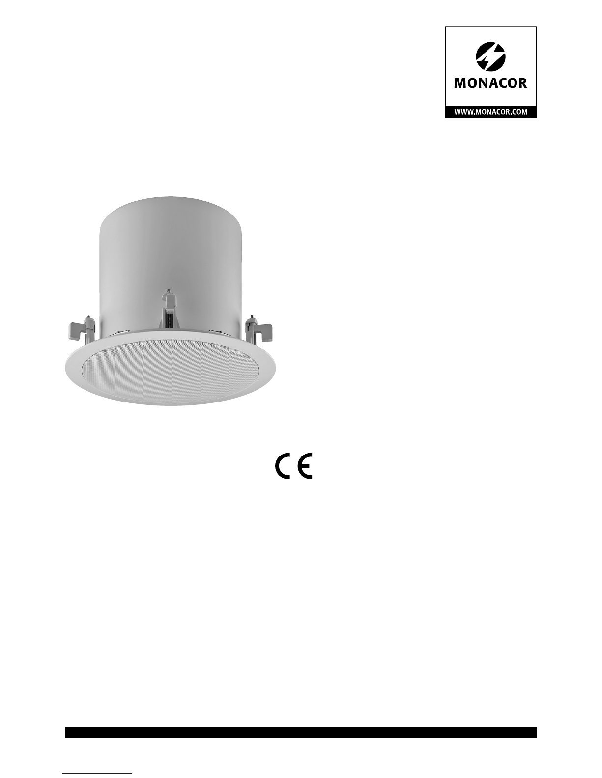
ELA-Subwoofer
für den Wand- und Deckeneinbau
PA Subwoofer
for Wall and Ceiling Installation
ESUB-6C / WS
Bestell-Nr. • Order No. 25.9340
INSTALLATIONSANLEITUNG
INSTALLATION INSTRUCTIONS
NOTICE D’INSTALLATION
ISTRUZIONI PER L’INSTALLAZIONE
INSTRUCCIONES DE INSTALACIÓN
INSTRUKCJA INSTALACJI
Page 2
2
Deutsch
40/20/10/5 W (100 V), 55 W (4 Ω)
MONACOR INTERNATIONAL·ZUM FALSCH 36·28307 BREMEN· GERMANY
ESUB-6C/WS
PA SUBWOOFER
100V
AUDIO
4Ω
0⏚ +
∅ 310
10
5 min.
32 max.
255
5
×
∅ 268
10 cm min.
1
1
1
1
1 1
1
5
6
7
4
3
2
2
2
ELA-Subwoofer für den Wandund Deckeneinbau
Diese Anleitung richtet sich an Installateure,
die Fachkenntnisse in der 100-V-Beschallungstechnik besitzen. Bitte lesen Sie die Anleitung
vor der Installation gründlich durch und heben
Sie sie für ein späteres Nachlesen auf.
1 Verwendungsmöglichkeiten
Dieser Subwoofer ist speziell für den Einsatz
in ELA-Beschallungsanlagen konzipiert und
dient zur Verbesserung der Basswiedergabe.
Er ist mit einem Übertrager für den Betrieb in
100-V-Anlagen ausgestattet, kann aber auch
direkt an einen niederohmigen Verstärkerausgang angeschlossen werden. Die Anpassung der Anschlussleistung erfolgt über einen
Drehschalter unter dem Lautsprechergitter.
2 Wichtige Hinweise
Der Lautsprecher entspricht allen relevanten Richtlinien der EU und trägt deshalb das
-Zeichen.
•
Verwenden Sie den Lautsprecher nur im Innenbereich. Schützen Sie ihn vor Tropf- und
Spritzwasser sowie vor hoher Luftfeuchtigkeit. Der zulässige Einsatztemperaturbereich beträgt 0 – 40 °C.
•
Verwenden Sie zum Reinigen nur ein tro-
ckenes, weiches Tuch, niemals Wasser oder
Chemikalien.
•
Wird der Lautsprecher zweckentfremdet,
nicht sicher montiert, falsch angeschlossen oder überlastet, kann keine Haftung
für daraus resultierende Sach- oder Personenschäden und keine Garantie für den
Lautsprecher übernommen werden.
Soll der Lautsprecher endgültig aus
dem Betrieb genommen werden,
übergeben Sie ihn zur umweltgerechten Entsorgung einem örtlichen
Recyclingbetrieb.
3 Installation
WARNUNG
Im Betrieb liegt berührungsgefährliche Spannung bis 100 V
an der Lautsprecherleitung an.
Die Installation darf nur durch
Fachpersonal erfolgen.
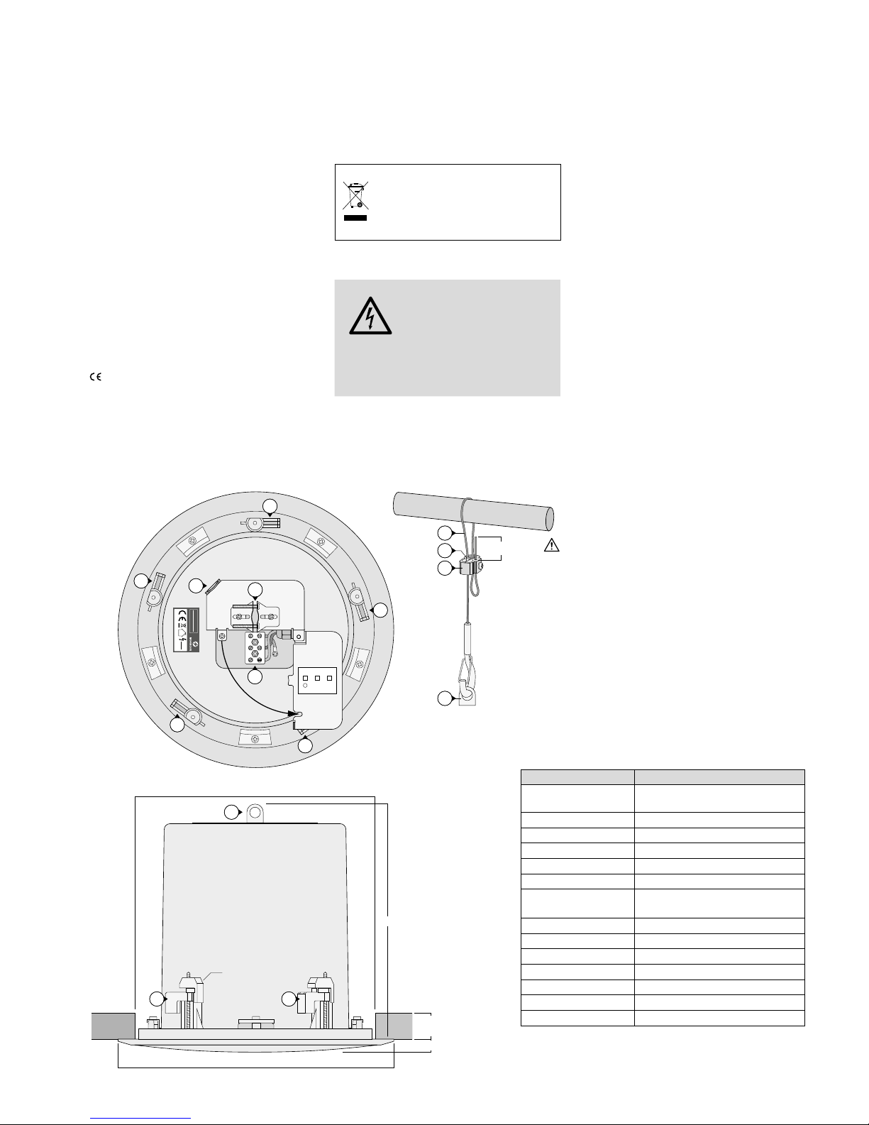
Achten Sie auf die Belastung des ELA-Verstärkers durch die Lautsprecher. Eine Überlastung kann den Verstärker beschädigen!
1)
Vor der Installation des Subwoofers den
ELA- Verstärker ausschalten, damit die
Lautsprecherleitung spannungsfrei ist!
2) In die Decke oder in die Wand eine Einbauöffnung mit einem Durchmesser von
268 mm sägen. Es muss eine Einbautiefe
von 255 mm vorhanden sein.
3)
Das Lautsprecherschutzgitter abziehen,
damit die Montageschrauben und der
Drehschalter für die Anschlussleistung
zugängig sind.
4)
Mit einem Schraubendreher am Drehschalter die gewünschte Nennleistung für den
100-V- Betrieb einstellen oder die Position
„4 Ω“ wählen, wenn der Lautsprecher direkt an einem niederohmigen Verstärkerausgang betrieben werden soll.
VORSICHT! In der Position „4 Ω“ den
Lautsprecher auf keinen Fall in einer
100-V-Anlage betreiben. Der Lautsprecher
und eventuell auch der Verstärker werden
beschädigt.
5)
Bei einem Deckeneinbau unbedingt das
beiliegende Fangseil (5) zur Montagesicherung anbringen.
a)
Das Seil aus der Seilklemme (7) herausziehen. Dazu die Arretierhülsen (6)
hin eindrücken.
b) Das Seil, wie in der Abbildung gezeigt,
an einer mechanisch stabilen Stelle befestigen.
c)
Die Seillänge so einstellen, dass bei
einem eventuellen Herausfallen aus der
Decke der Fallweg möglichst kurz ist.
d)
Nach dem Anschließen des Subwoofers
den Karabinerhaken in die Sicherungsöse (2) der Subwoofers einhaken.
6)
Das Lautsprecherkabel durch die Kabelklemme (3) führen, an die Schraubklemmen „0“ und „+“ (4) anschließen und mit
der Kabelklemme festklemmen.
7)
Vor dem Einsetzen des Lautsprechers in
das Montageloch sicherstellen, dass sich
die fünf Klemmstücke (1) in ihrer Ausgangsposition befinden (siehe Zeichnung
der Draufsicht). Dann den Lautsprecher in
das Loch einsetzen und ihn durch Anziehen der Montageschrauben festklemmen.
8) Das Schutzgitter wieder aufsetzen.
Änderungen vorbehalten.
Technische Daten ESUB-6C / WS
Nennbelastbarkeit
100 V: 40 / 20 / 10 W
4 Ω: 55 W
Musikbelastbarkeit 110 W
Frequenzbereich
45 – 280 Hz
Kennschalldruck 88 dB (1 W/1 m)
Max. Nennschalldruck 104 dB
Abstrahlwinkel 180°
Lautsprechertyp
Bandpass-Subwoofer mit
16-cm-Langhubmembran (6”)
Deckenstärke
5 – 32 mm
Einbauöffnung ⌀ 268 mm
Einbautiefe 255 mm
Abmessungen ⌀ 310 mm × 265 mm
Gewicht 5 kg
Anschluss Keramik-Schraubklemmen
Einsatztemperatur
0 – 40 °C
Diese Bedienungsanleitung ist urheberrechtlich für MONACOR ®
INTERNATIONAL GmbH & Co. KG geschützt. Eine Reproduktion für
eigene kommerzielle Zwecke – auch auszugsweise – ist untersagt.
Page 3
3
English
40/20/10/5 W (100 V), 55 W (4 Ω)
MONACOR INTERNATIONAL
·
ZUM FALSCH 36
·
28307 BREMEN
·
GERMANY
ESUB-6C/WS
PA SUBWOOFER
100V
AUDIO
4Ω
0⏚ +
∅ 310
10
5 min.
32 max.
255
5
×
∅ 268
10 cm min.
1
1
1
1
1 1
1
5
6
7
4
3
2
2
2
PA Subwoofer for Wall and
Ceiling Installation
These instructions are intended for installers
with specific knowledge in sound reproduction using 100 V technology. Please read the
instructions carefully prior to installation and
keep them for later reference.
1 Applications
This subwoofer is specially designed for PA
systems. It is used to improve bass reproduction. The subwoofer is provided with a
transformer for operation in 100 V systems,
but it can also be directly connected to a lowimpedance amplifier output. A rotary switch
behind the speaker grille is used to match the
connected load.
2 Important Notes
The speaker corresponds to all relevant directives of the EU and is therefore marked
with .
•
The speaker is suitable for indoor use only.
Protect it against dripping water, splash
water and high air humidity. The admissible ambient temperature range is 0 – 40 °C.
•
For cleaning only use a dry, soft cloth; never
use water or chemicals.
•
No guarantee claims for the speaker and
no liability for any resulting personal damage or material damage will be accepted
if the speaker is used for other purposes
than originally intended, if it is not safely
installed or not correctly connected, or if it
is overloaded.
If the speaker is to be put out of operation definitively, take it to a local
recycling plant for a disposal which
is not harmful to the environment.
3 Installation
WARNING
During operation, there is a
hazard of contact with a dangerous voltage of up to 100 V
at the speaker cable. Installation must be made by skilled
personnel only.
Always observe the load of the PA amplifier
by the speakers. An overload may damage
the amplifier!
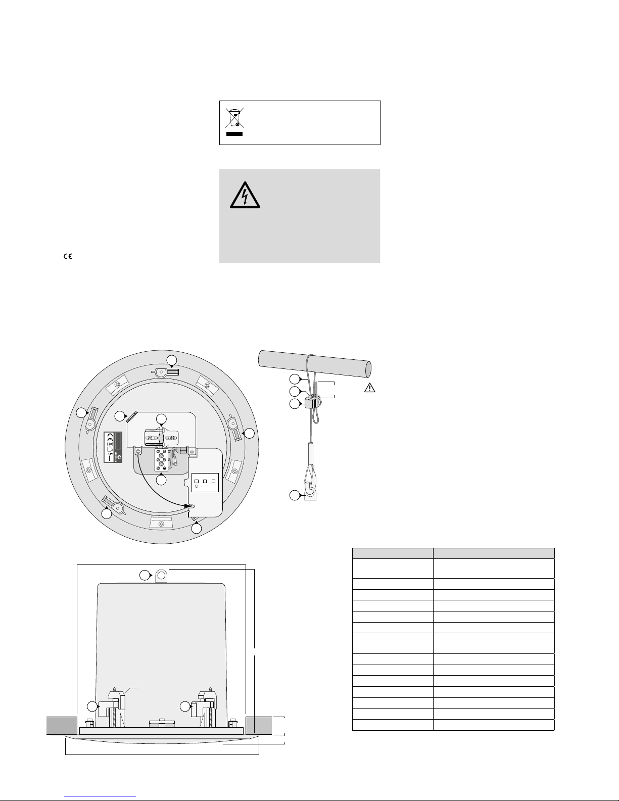
1)
Before installing the subwoofer, switch off
the PA amplifier so that the speaker cable
will not carry any voltage!
2)
Saw a mounting hole (⌀ 268 mm) into the
ceiling or wall. The mounting depth must
be 255 mm.
3)
Remove the speaker grille to access the
mounting screws and the rotary switch
for the connected load.
4) Use a screwdriver to adjust the rated load
for 100 V operation on the rotary switch.
For direct operation at a low-impedance
amplifier output, set the switch to the
position “4 Ω”.
CAUTION! Never use the position
“4 Ω”when the speaker is operated in a
100 V system: The speaker and possibly
also the amplifier will be damaged.
5) For ceiling installation, always attach the
safety rope (5) provided to secure the subwoofer.
a) Press on the locking sleeves (6) to pull
the rope from the rope clip (7).
b)
Attach the rope to a mechanically stable
spot (see drawing).
c) Adjust the rope length in such a way
that the fall distance will be as short
as possible if the subwoofer falls from
the ceiling.
d)
After connecting the subwoofer, attach
the spring hook of the rope to the eyebolt (2) of the subwoofer.
6) Pull the speaker cable through the cable
clip (3), connect the cable to the screw
terminals “0” and “+” (4) and use the
cable clip to fasten the cable.
7)
Make sure that the five clamping pieces
(1) are in their initial positions (see top
view) before inserting the speaker into the
mounting hole. Insert the speaker into the
hole and fasten the mounting screws to
secure the speaker.
8) Replace the speaker grille.
Subject to technical modification.
Specifications ESUB-6C / WS
Power rating
100 V: 40 / 20 / 10 W
4 Ω: 55 W
Music power 110 W
Frequency range
45 – 280 Hz
SPL 88 dB (1 W/1 m)
Max. SPL 104 dB
Radiation angle 180°
Type of speaker
band-pass subwoofer with
16 cm (6“) long-excursion driver
Ceiling thickness 5 – 32 mm
Mounting hole ⌀ 268 mm
Mounting depth 255 mm
Dimensions ⌀ 310 mm × 265 mm
Weight 5 kg
Connection ceramic screw terminals
Ambient temperature
0 – 40 °C
All rights reserved by MONACOR ® INTERNATIONAL GmbH & Co.KG.
No part of this instruction manual may be reproduced in any form
or by any means for any commercial use.
Page 4

4
Français
40/20/10/5 W (100 V), 55 W (4 Ω)
MONACOR INTERNATIONAL·ZUM FALSCH 36·28307 BREMEN· GERMANY
ESUB-6C/WS
PA SUBWOOFER
100V
AUDIO
4Ω
0⏚ +
∅ 310
10
5 min.
32 max.
255
5
×
∅ 268
10 cm min.
1
1
1
1
1 1
1
5
6
7
4
3
2
2
2
Subwoofer Public Adress pour
montage mur ou plafond
Cette notice s’adresse aux installateurs ayant
des connaissances techniques en sonorisation 100 V. Veuillez lire la présente notice avec
attention avant l‘installation et conservez-la
pour pouvoir vous y reporter ultérieurement.
1 Possibilités d‘utilisation
Ce subwoofer est spécialement conçu pour
une utilisation dans des installations de sonorisation Public Adress et permet d‘améliorer la restitution des graves. Il est doté d‘un
transformateur pour fonctionnement dans
des installations 100 V, mais il peut également
être branché directement à une sortie amplificateur basse impédance. L‘adaptation à la
puissance connectée se fait via un sélecteur
rotatif sous la grille haut-parleur.
2 Conseils importants
Le haut-parleur répond à toutes les directives
nécessaires de l‘Union européenne et porte
donc le symbole
.
•
Le haut-parleur n‘est conçu que pour une
utilisation en intérieur. Protégez-le des
éclaboussures, de tout type de projections
d‘eau et d’une humidité d‘air élevée. La
plage de température ambiante admissible
est de 0 – 40 °C.
•
Pour le nettoyage, utilisez uniquement un
chiffon sec et doux, en aucun cas de produits chimiques ou d‘eau.
•
Nous déclinons toute responsabilité en cas
de dommages matériels ou corporels résultants si le haut-parleur est utilisé dans
un but autre que celui pour lequel il a été
conçu, s‘il n‘est pas installé de manière sûre
ou n‘est pas correctement branché ou s’il y
a surcharge ; en outre, la garantie deviendrait caduque.
Lorsque le haut-parleur est définitivement retiré du service, vous devez
le déposer dans une usine de recyclage adaptée pour contribuer à son
élimination non polluante.
CARTONS ET EMBALLAGE
PAPIER À TRIER
3 Installation
AVERTISSEMENT
Pendant le fonctionnement,
une tension de contact dangereuse jusqu’à 100 V est
présente sur le câble haut-
parleur. Seul un personnel qualifié peut effectuer l‘installation.
Faites attention à la charge de l‘amplificateur
PA par les haut-parleurs. Une surcharge peut
endommager l‘amplificateur !
1)
Avant d‘installer le subwoofer, éteignez
l‘amplificateur Public Adress pour que le
câble haut-parleur ne soit pas porteur de
tension.
2)
Percez, dans le plafond ou le mur, une
découpe avec un diamètre de 268 mm. Il
faut que la profondeur de montage soit
de 255 mm.
3) Retirez la grille haut-parleur pour que les
vis de montage et le sélecteur de la puissance connectée soient accessibles.
4)
Avec un tournevis, réglez sur le sélecteur la
puissance nominale souhaité pour le fonctionnement 100 V ou, pour un fonctionnement direct à une sortie amplificateur basse
impédance, sélectionnez la position «4 Ω».
ATTENTION ! En position «4 Ω», ne faites
jamais fonctionner le haut-parleur dans
une installation 100 V. Le haut-parleur et
éventuellement l‘amplificateur peuvent
être endommagés.
5)
Pour un montage au plafond, utilisez
impérativement l‘élingue livrée (5) pour
sécuriser le montage.
a)
Appuyez sur les manchons de verrouillage (6) pour retirer l‘élingue de
la pince(7).
b)
Comme indiqué sur le schéma, fixez
l‘élingue à un endroit mécaniquement
stable.
c) Réglez la longueur de l‘élingue de telle
sorte que la distance de chute soit la
plus courte possible en cas de chute du
subwoofer du plafond.
d) Une fois le subwoofer branché, accro-
chez le mousqueton dans l‘œillet de
fixation (2) du subwoofer.
6)
Faites passer le câble haut-parleur via le
serre-câble (3), reliez-le aux bornes à vis
«0» et «+» (4) et fixez-le avec le serre-câble.
7)
Avant de placer le haut-parleur dans le
trou de montage, assurez-vous que les
cinq pinces (1) sont bien dans leur position
d‘origine (voir dessin de la vue de dessus).
Ensuite, mettez le haut-parleur dans le
trou, fixez-le en serrant les vis de montage.
8) Replacez la grille de protection.
Tout droit de modification réservé.
Caractéristiques techniques ESUB-6C / WS
Puissance nominale
100 V: 40 / 20 / 10 W
4 Ω: 55 W
Puissance musique 110 W
Bande passante
45 – 280 Hz
Pression sonore nominale 88 dB (1 W/1 m)
Pression sonore nominale max. 104 dB
Angle de diffusion 180°
Type haut-parleur
subwoofer passe bande avec membrane
16 cm (6”) à grand débattement
Epaisseur plafond 5 – 32 mm
Découpe de montage ⌀ 268 mm
Profondeur de montage 255 mm
Dimensions ⌀ 310 mm × 265 mm
Poids 5 kg
Branchement bornes à vis céramiques
Température fonc.
0 – 40 °C
Notice d’utilisation protégée par le copyright de MONACOR ® INTERNATIONAL GmbH & Co. KG. Toute reproduction même partielle à des fins
commerciales est interdite.
Page 5

5
Italiano
40/20/10/5 W (100 V), 55 W (4 Ω)
MONACOR INTERNATIONAL
·
ZUM FALSCH 36
·
28307 BREMEN
·
GERMANY
ESUB-6C/WS
PA SUBWOOFER
100V
AUDIO
4Ω
0⏚ +
∅ 310
10
5 min.
32 max.
255
5
×
∅ 268
10 cm min.
1
1
1
1
1 1
1
5
6
7
4
3
2
2
2
Subwoofer PA per il montaggio
a parete e in soffitto
Queste istruzioni sono rivolte agli installatori
che hanno conoscenze specifiche nella tecnica di sonorizzazione a 100 V. Vi preghiamo
di leggerle attentamente prima dell’installazione e di conservarle per un uso futuro.
1 Possibilità d’impiego
Questo subwoofer è stato realizzato specialmente per l’impiego in impianti PA di sonorizzazione e serve a migliorare la riproduzione
dei bassi. È equipaggiato con un trasformatore per l’uso in impianti a 100 V, ma può
essere collegato anche direttamente con
l’uscita a bassa impedenza di un amplificatore. L’adattamento alla potenza di collegamento avviene tramite una manopola sotto
la griglia dell’altoparlante.
2 Avvertenze importanti
Il diffusore è conforme a tutte le direttive
rilevanti dell’UE e pertanto porta la sigla .
•
Usare il diffusore solo all’interno di locali.
Proteggerlo dall’acqua gocciolante e dagli
spruzzi d’acqua nonché da alta umidità
dell’aria. La temperatura d’esercizio ammessa è 0 – 40 °C.
•
Per la pulizia usare solo un panno morbido,
asciutto; non impiegare mai acqua o prodotti chimici.
•
Nel caso d’uso improprio, di montaggio
non sicuro, di collegamenti sbagliati o di
sovraccarico del diffusore, non si assume
nessuna responsabilità per eventuali danni
consequenziali a persone o a cose e non si
assume nessuna garanzia per il diffusore.
Se si desidera eliminare il diffusore
definitivamente, consegnarlo per lo
smaltimento ad un’istituzione locale
per il riciclaggio.
3 Installazione
AVVERTIMENTO Durante il funzionamento,
nel cavo verso il diffusore è
presente una tensione fino
a 100 V, pericolosa in caso
di contatto. L’installazione
deve essere eseguita solo
da personale specializzato.
Tener presente anche il carico dell’amplificatore PA da parte degli altoparlanti. Un sovraccarico può danneggiare l’amplificatore!
1) Prima di installare Il subwoofer spegnere
l’amplificatore PA per togliere la tensione
dal cavo verso il diffusore!
2) Nel soffitto o nella parete praticare un’a-
pertura di montaggio con un diametro
di 268 mm. È richiesta una profondità di
montaggio di 255 mm.
3) Staccare la griglia protettiva davanti all’altoparlante per rendere accessibili le viti di
montaggio e la manopola per il cavo di
collegamento.
4) Con un cacciavite impostare sulla manopola la potenza nominale richiesta per il
funzionamento a 100 V, oppure scegliere la
posizione “4 Ω”, se il diffusore deve essere
usato direttamente con un’uscita a bassa
impedenza di un amplificatore.
ATTENZIONE! In posizione “4 Ω” non
usare assolutamente il diffusore con un impianto a 100 V. Il diffusore e eventualmente
anche l’amplificatore saranno danneggiati.
5) In caso di montaggio in un soffitto, applicare assolutamente la fune di trattenuta (5)
in dotazione per assicurare il montaggio.
a) Sfilare la fune dal suo morsetto (7). Per
fare ciò spingere indentro le boccole di
bloccaggio (6).
b) Come si vede dall’illustrazione, fissare
la fune in un punto stabile meccanicamente.
c)
Regolare la lunghezza della fune in
modo che in caso di un’eventuale caduta dal soffitto, la caduta sia la più
corta possibile.
d)
Dopo il collegamento del subwoofer,
agganciare il moschettone nell’asola di
sicurezza (2) del subwoofer.
6) Portare il cavo dell’altoparlante attraverso
il morsetto (3), collegarlo con i morsetti
“0“ e “+“ (4) e bloccarlo con il morsetto.
7)
Prima di inserire il diffusore nell’apertura di
montaggio assicurarsi che i cinque morsetti
(1) si trovino nella loro posizione iniziale
(vedi il disegno dall’alto). Quindi inserire il
diffusore nell’apertura e fissarlo stringendo
le viti di montaggio.
8) Rimettere la griglia protettiva.
Con riserva di modifiche tecniche.
Dati tecnici ESUB-6C / WS
Potenza nominale
100 V: 40 / 20 / 10 W
4 Ω: 55 W
Potenza musicale 110 W
Banda passante
45 – 280 Hz
Livello di press. sonora 88 dB (1 W/1 m)
Liv. di press. son. max 104 dB
Angolo d’irradiazione 180°
Tipo altoparlante
Subwoofer passabanda con
membrana a corsa lunga di 16 cm (6”)
Spessore soffitto 5 – 32 mm
Apertura di montaggio ⌀ 268 mm
Profondità di montaggio 255 mm
Dimensioni ⌀ 310 mm × 265 mm
Peso 5 kg
Contatti Morsetti a vite di ceramica
Temperatura d’esercizi
0 – 40 °C
La MONACOR ® INTERNATIONAL GmbH & Co. KG si riserva ogni
diritto di elaborazione in qualsiasi forma delle presenti istruzioni
per l’uso. La riproduzione – anche parziale – per propri scopi commerciali è vietata.
Page 6

6
Español
40/20/10/5 W (100 V), 55 W (4 Ω)
MONACOR INTERNATIONAL·ZUM FALSCH 36·28307 BREMEN· GERMANY
ESUB-6C/WS
PA SUBWOOFER
100V
AUDIO
4Ω
0⏚ +
∅ 310
10
5 min.
32 max.
255
5
×
∅ 268
10 cm min.
1
1
1
1
1 1
1
5
6
7
4
3
2
2
2
el cable de altavoz no contenga ningún
voltaje.
2) Haga un agujero de montaje (⌀ 268 mm)
en el techo o en la pared. La profundidad
de montaje debe ser de 255 mm.
3) Extraiga la rejilla del altavoz para acceder
a los tornillos de montaje y al interruptor
rotatorio para la carga conectada.
4)
Utilice un destornillador para ajustar la
carga conectada para el funcionamiento
a 100 V en el interruptor rotatorio. Para el
funcionamiento directo en una salida de
amplificador de baja impedancia, ajuste el
interruptor en la posición “4 Ω”.
¡PRECAUCIÓN! No utilice nunca la posición “4 Ω” cuando el altavoz se utilice
en un sistema de 100 V: Podría dañarse
el altavoz y posiblemente el amplificador.
5)
Para la instalación en techo, utilice siempre
el cable de seguridad (5) entregado para
asegurar el subwoofer.
a)
Presione los casquillos de cierre (6)
para estirar el cable desde la pinza del
cable(7).
b)
Fije el cable en un lugar mecánicamente
estable (ver esquema).
c)
Ajuste la longitud del cable de modo
que la distancia de caída sea la menor
posible si el subwoofer cayera del
techo.
d) Después de conectar el subwoofer, fije
el mosquetón del cable en el ojal (2)
del subwoofer.
6)
Pase el cable de altavoz por la pinza de
cable (3), conecte el cable a los terminales
de rosca “0” y “+” (4) y utilice la pinza de
cable para fijar el cable.
7)
Antes de introducir el altavoz en el agujero
de montaje, asegúrese de que las cinco
piezas de agarre (1) están en su posición
inicial (ver vista en planta). Inserte el altavoz en el agujero y fije los tornillos de
montaje para asegurar el altavoz.
8) Recoloque la rejilla del altavoz.
Sujeto a modificaciones técnicas.
Subwoofer de Megafonía para
Instalación en Pared y Techo
Estas instrucciones van dirigidas a instaladores
con conocimientos específicos sobre sonido
mediante 100 V. Lea atentamente estas instrucciones antes de la instalación y guárdelas
para usos posteriores.
1 Aplicaciones
Este subwoofer está diseñado especialmente
para sistemas de megafonía. Se utiliza para
mejorar la reproducción de graves. Este subwoofer está equipado con un transformador
para funcionar en sistemas de 100 V, pero
también se puede conectar directamente a
una salida de baja impedancia de un amplificador. Para adecuar la carga conectada, se
utiliza un interruptor rotatorio tras la rejilla
del altavoz.
2 Notas Importantes
El altavoz cumple con todas las directivas relevantes de la UE y por lo tanto está marcado
con el símbolo .
•
El altavoz está adecuado sólo para aplicaciones en interiores. Protéjalo contra
goteos, salpicaduras y humedad elevada.
Rango de temperatura ambiente admisible:
0 – 40 ºC.
•
Utilice sólo un paño suave y seco para la
limpieza; no utilice nunca ni agua ni productos químicos.
•
No podrá reclamarse garantía o responsabilidad alguna por cualquier daño personal
o material resultante si el altavoz se utiliza
para otros fines diferentes a los originalmente concebidos, si no se instala o no se
conecta adecuadamente o si se sobrecarga.
Si va a poner el altavoz fuera de
servicio definitivamente, llévelo a la
planta de reciclaje de la zona para
que su eliminación no sea perjudicial
para el medio ambiente.
3 Instalación
ADVERTENCIA
Durante el funcionamiento,
hay peligro de contacto con
un voltaje de hasta 100 V en
el cable de altavoz. Sólo un
técnico debe realizar la ins-
talación.
Preste atención a la carga de los altavoces en
el amplificador de megafonía. ¡Una sobrecarga podría dañar el amplificador!
1)
Desconecte el sistema de megafonía antes
de instalar el subwoofer, de modo que
Especificaciones ESUB-6C / WS
Potencia nominal
100 V: 40 / 20 / 10 W
4 Ω: 55 W
Potencia musical 110 W
Rango de frecuencias
45 – 280 Hz
SPL 88 dB (1 W/1 m)
Máx. SPL 104 dB
Ángulo de radiación 180°
Tipo de altavoz
Subwoofer pasa banda con mem-
brana de 16 cm (6”) de gran excursión
Grosor del techo 5 – 32 mm
Agujero de montaje ⌀ 268 mm
Profundidad de montaje 255 mm
Dimensiones ⌀ 310 mm × 265 mm
Peso 5 kg
Conexión Terminales cerámicos de rosca
Temperatura ambiente
0 – 40 °C
Manual de instrucciones protegido por el copyright de MONACOR ®
INTERNATIONAL GmbH & Co. KG. Toda reproducción mismo parcial
para fines comerciales está prohibida.
Page 7

7
Polski
40/20/10/5 W (100 V), 55 W (4 Ω)
MONACOR INTERNATIONAL
·
ZUM FALSCH 36
·
28307 BREMEN
·
GERMANY
ESUB-6C/WS
PA SUBWOOFER
100V
AUDIO
4Ω
0⏚ +
∅ 310
10
5 min.
32 max.
255
5
×
∅ 268
10 cm min.
1
1
1
1
1 1
1
5
6
7
4
3
2
2
2
aby kabel głośnikowy nie znajdował się
pod napięciem!
2) W odpowiednim miejscu w suficie wyciąć
okrągły otwór (⌀ 268 mm). Głębokość
montażowa głośnika wynosi 255 mm.
3)
Zdjąć maskownicę, aby uzyskać dostęp do
śrub montażowych oraz przełącznika trybu
pracy i wyboru mocy.
4) Za pomocą cienkiego śrubokręta ustawić
regulator na żądaną moc dla trybu 100 V,
lub przełączyć głośnik na tryb “4 Ω”, odpowiedni do współpracy ze wzmacniaczem
niskoimpedancyjnym.
UWAGA! Nie wolno przełączać głośnika
na tryb “4 Ω” jeżeli jest on podłączony do
wzmacniacza 100 V: istnieje duże ryzyko
uszkodzenia zarówno wzmacniacza jak i
samego głośnika.
5)
W przypadku montażu w suficie, należy
dodatkowo zabezpieczyć głośnik dołączoną linką (5).
a)
Wcisnąć zaciski blokujące (6) aby zwolnić koniec linki z zaczepu (7).
b)
Przymocować linkę do stropu lub stabilnego punktu konstrukcji sufitu (patrz
rysunek).
c) Wyregulować długość linki, aby ewen-
tualna wysokość upadku głośnika była
jak najmniejsza.
d)
Po podłączeniu subwoofera, zaczepić
uchwyt sprężynowy linki o oczko (2) na
obudowie głośnika.
6)
Przeprowadzić kabel głośnikowy przez
zaczep (3), podłączyć go do terminali
śrubowych “0” oraz “+” (4) a następnie
zabezpieczyć blokadą.
7)
Przed umieszczeniem głośnika w otworze,
upewnić się, że wszystkie pięć zaczepów
montażowych (1) znajduje się w pozycji
wyjściowej (patrz widok z góry). Zamontować głośnik skręcając wszystkie śruby
zaczepów montażowych.
8) Zamontować maskownicę głośnika.
Z zastrzeżeniem możliwości zmian.
Subwoofer PA do
montażuwpustowego
Niniejsza instrukcja przeznaczona jest instalatorów posiadających wiedzę w zakresie systemów PA pracujących w technice 100 V. Przed
rozpoczęciem użytkowania proszę zapoznać
się z instrukcją, a następnie zachować ją do
wglądu.
1 Zastosowanie
Subwoofer pozwala na poprawę brzmienia
odtwarzanej muzyki, poprzez reprodukcję
pasma basowego. Przystosowany jest do
pracy w systemach PA wykorzystujących technikę 100 V, ale może również współpracować
ze wzmacniaczami niskoimpedancyjnymi. Pod
maskownicą znajduje się regulator służący
do wyboru trybu pracy oraz mocy głośnika.
2 Środki bezpieczeństwa
Głośnik spełnia wszystkie wymagania norm UE
dzięki temu został oznaczony symbolem .
•
Głośnik przeznaczony jest tylko do zastosowań wewnętrznych. Należy chronić go
przez wodą, dużą wilgotnością oraz wysokimi temperaturami. Dopuszczalny zakres
0 – 40 °C.
•
Do czyszczenia należy używać suchej i
miękkiej ściereczki, nie używać wody ani
środków chemicznych.
•
Producent i dostawca nie ponoszą odpowiedzialności za powstałe szkody: uszkodzenia sprzętu bądź obrażenia użytkownika, jeżeli głośnik był używany niezgodnie
z przeznaczeniem, niepoprawnie zainstalowany, podłączony lub przeciążony.
Jeśli głośnik nie będzie już więcej
używany, wskazane jest przekazanie
go do miejsca utylizacji odpadów,
aby został zniszczony bez szkody dla
środowiska.
3 Montaż
UWAGA
W czasie pracy, na złączach
oraz w kablu głośnikowym występuje niebezpieczne wysokie
napięcie do 100 V. Instalacja
powinna być wykonywana
wyłącznie przez osoby prze-
szkolone.
Przed podłączeniem głośnika należy zawsze
sprawdzić jakie jest dopuszczalne obciążenie
wzmacniacza. Sumaryczna moc głośników
nie może przekraczać mocy wzmacniacza!
W przeciwnym wypadku wzmacniacz ulegnie uszkodzeniu.
1) Przed przystąpieniem do podłączania głośników należy wyłączyć wzmacniacz PA,
Specyfikacja ESUB-6C / WS
Moc znamionowa
100 V: 40 / 20 / 10 W
4 Ω: 55 W
Moc muzyczna 110 W
Pasmo przenoszenia
45 – 280 Hz
SPL 88 dB (1 W/1 m)
Max. SPL 104 dB
Kąt promieniowania 180°
Typ głośnika
16 cm (6”) niskotonowy o
dużym wychyleniu
Grubość sufitu
5 – 32 mm
Otwór montażowy ⌀ 268 mm
Głębokość montażowa 255 mm
Wymiary ⌀ 310 mm × 265 mm
Waga 5 kg
Połączenie ceramiczne terminale śrubowe
Zakres temperatur
0 – 40 °C
Instrukcje obsługi są chronione prawem copyright for MONACOR ®
INTERNATIONAL GmbH & Co. KG. Przetwarzanie całości lub części
instrukcji dla osobistych korzyści finansowych jest zabronione.
Page 8

MONACOR INTERNATIONAL GmbH & Co. KG • Zum Falsch 36 • 28307 Bremen • Germany
Copyright© by MONACOR INTERNATIONAL. All rights reserved.
A-1885.99.01.01.2018
 Loading...