

Page 1
DN-2618 Bestell-Nr. • Order No. 12.2260
High
I N P U T
ELECTRONICS FOR SPECIALISTS ELECTRONICS FOR SPECIALISTS ELECTRONICS FOR SPECIALISTS ELECTRONICS FOR SPECIALISTS ELECTRONICS FOR SPECIALISTS ELECTRONICS
Wird die Frequenzweiche zweckentfremdet,
2-Wege-Frequenzweiche
fürLautsprecherboxen
Diese Anleitung richtet sich an Selbst-
DeutschEnglish
bau-Amateure von Lautsprecherboxen mit
entsprechenden Grundkenntnissen. Bitte
lesen Sie die Anleitung vor dem Betrieb
gründlich durch und heben Sie sie für ein
späteres Nachlesen auf.
1 Verwendungsmöglichkeiten
Diese Frequenzweiche ist speziell für den Aufbau einer 2-Wege-Lautsprecherbox mit einer
Belastbarkeit von bis zu 350 W konzipiert.
2 Wichtige Hinweise
für den Gebrauch
Die Frequenzweiche entspricht allen relevanten Richtlinien der EU und trägt deshalb das
-Zeichen.
Die Frequenzweiche ist nur zur Verwendung
•
im Innenbereich geeignet. Schützen Sie sie
vor Tropf- und Spritzwasser, hoher Luftfeuchtigkeit und Hitze (zulässiger Einsatztemperaturbereich 0 – 40 °C).
Verwenden Sie zum Reinigen nur einen tro-
•
ckenen, weichen Pinsel, auf keinen Fall Wasser oder Chemikalien.
•
falsch angeschlossen, überlastet oder nicht
fachgerecht repariert, kann keine Haftung
für daraus resultierende Sach- oder Personenschäden und keine Garantie für die
Weiche übernommen werden.
Soll die Frequenzweiche endgültig
aus dem Betrieb genommen werden,
übergeben Sie sie zur umweltgerechten Entsorgung einem örtlichen Recyclingbetrieb.
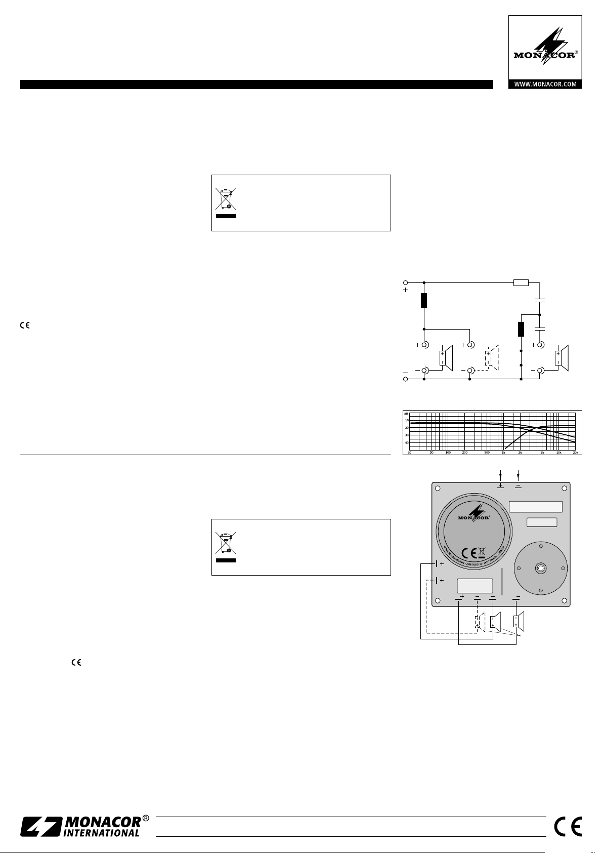
3 Anschluss
1) Den Bass- / Mitteltonlautsprecher (Impedanz
4 Ω oder 8 Ω entsprechend der gewünschten Trennfrequenz, ☞ Techn. Daten) an
die Stifte „BM+“ und „BM−“ anschließen
(Abb. 3). Es können auch zwei 8-Ω-Lautsprecher parallel angeschlossen werden.
2) Den Hochtöner (Impedanz 8 Ω) an die Stifte
„H+“ und „H−“ anschließen. Der richtige
Anschluss der Plus- und Minuskontakte
hängt von den eingesetzten Lautsprechern
sowie von ihrer Anordnung in der Box ab
und muss durch Probieren ermittelt werden.
3) Die Stifte „IN“ dienen als Signaleingang.
4 Technische Daten
Eingangsbelastbarkeit: . .max. 350 W
Ausgangsimpedanz: . . . .8 Ω (Bass auch 4 Ω)
Trennfrequenz
Tiefpass bei 4 / 8 Ω: . . . .1700 Hz / 3000 Hz
Hochpass: . . . . . . . . . . .3000 Hz
Flankensteilheit
Tiefpass: . . . . . . . . . . . . 6 dB /Oktave
Hochpass: . . . . . . . . . . .18 dB /Oktave
Abmessungen: . . . . . . . .125 × 32 × 110 mm
Gewicht: . . . . . . . . . . . . .400 g
Änderungen vorbehalten.
L 1
0m68
1 × Bass / Mid 4 Ω or 8 Ω or
2 × Bass / Mid 8 Ω
BM
BM
➀
L 2
0m27
Rx
R1
4Ω7
10 W
C 1
3µ
150 V
MKT
C 2
10µ
150 V
MKT
H
8 Ω
2-Way Crossover Network
for Speaker Systems
These instructions are intended for nonprofessionals with basic knowledge in DIY
speaker building. Please read the instructions carefully prior to operation and keep
them for later reference.
1 Applications
This crossover network is specially designed
for setting up a 2-way speaker system with a
power capability of up to 350 W.
2 Important Notes
The crossover network corresponds to all relevant directives of the EU and is therefore
marked with .
The crossover network is suitable for indoor
•
use only. Protect it against dripping water
and splash water, high air humidity and heat
(admissible ambient temperature range:
0 – 40 °C).
For cleaning only use a dry, soft brush; never
•
use water or chemicals.
No guarantee claims for the crossover net-
•
work and no liability for any resulting personal damage or material damage will be
accepted if the crossover network is used for
other purposes than originally intended, it it
is not correctly connected, if it is overloaded,
or if it is not repaired in an expert way.
If the crossover network is to be put
out of operation definitively, take it to
a local recycling plant for a disposal
which is not harmful to the environment.
3 Connection
1) Connect the bass / midrange speaker (4 Ω or
8 Ω impedance depending on the desired
crossover frequency, ☞ specifications) to
the pins “BM+” and “BM−” (fig. 3). Two
8 Ω speakers may be connected in parallel.
2) Connect the tweeter (8 Ω impedance) to the
pins “H+” and “H−”. The correct connection of the positive and negative contacts
depends on the speakers used and their
arrangement within the speaker system. To
find the ideal connection for your speaker
configuration, test the options with a sound
check.
3) The pins “IN” are used as a signal input.
➁
➂
BM
DN-2618
Best.-Nr. 12.2260
350 WMAX
C 2
H
Input
IN
L 1
Rx
BM H
BM 8 ΩH
BM
R 1
C 1
L 2
1 × Bass / Mid 4 Ω or 8 Ω or
2 × Bass / Mid 8 Ω
4 Specifications
Input power: . . . . . . . . . .350 W max.
Output impedance: . . . . .8 Ω (bass also 4 Ω)
Crossover frequency
Low pass at 4 / 8 Ω: . . . .1700 Hz / 3000 Hz
High pass: . . . . . . . . . . .3000 Hz
Slope
Low pass: . . . . . . . . . . . 6 dB / octave
High pass: . . . . . . . . . . 18 dB / octave
Dimensions: . . . . . . . . . .125 × 32 × 110 mm
Weight: . . . . . . . . . . . . .400 g
MONACOR INTERNATIONAL GmbH & Co. KG • Zum Falsch 36 • 28307 Bremen • Germany
Copyright© by MONACOR INTERNATIONAL. All rights reserved.
Subject to technical modification.
A-1726.99.01.11.2015
Page 2

High
I N P U T
DN-2618 Référence num. • Codice 12.2260
ELECTRONICS FOR SPECIALISTS ELECTRONICS FOR SPECIALISTS ELECTRONICS FOR SPECIALISTS ELECTRONICS FOR SPECIALISTS ELECTRONICS FOR SPECIALISTS ELECTRONICS
Filtre de fréquences 2 voies
pour enceintes
Cette notice s’adresse aux non-profession-
FrançaisItaliano
nels avec des connaissances de base dans
la conception d’enceintes. Veuillez lire la
présente notice avec attention avant le
fonctionnement et conservez-la pour pouvoir vous y reporter ultérieurement.
1 Possibilités d’utilisation
Ce filtre de fréquences est spécialement conçu
pour le montage d’une enceinte 2 voies avec
une puissance de 350 W max.
2 Conseils importants
d’utilisation
Le filtre de fréquences répond à toutes les directives nécessaires de l’Union européenne et
porte donc le symbole .
Le filtre de fréquences n’est conçu que pour
•
une utilisation en intérieur. Protégez-le des
éclaboussures, de tout type de projections
d’eau, d’une humidité élevée de l’air et de
la chaleur (température ambiante admissible
0 – 40 °C).
Pour le nettoyage, utilisez uniquement une
•
brosse sèche, douce, en aucun cas de produits chimiques ou d’eau.
Nous déclinons toute responsabilité en cas
•
de dommages matériels ou corporels résul-
tants si le filtre de fréquences est utilisé dans
un but autre que celui pour lequel il a été
conçu, s’il n’est pas correctement branché,
s’il y a surcharge ou s’il n’est pas réparé par
une personne habilitée; en outre, la garantie
deviendrait caduque.
Lorsque le filtre de fréquences est définitivement retiré du service, vous devez
le déposer dans une usine de recyclage
adaptée pour contribuer à son élimination non polluante.
CARTONS ET EMBALLAGE
PAPIER À TRIER
3 Branchement
1) Reliez le haut-parleur de grave / médium (impédance 4 Ω ou 8 Ω selon la fréquence de
coupure voulue, ☞ caractéristiques techn.)
aux pins «BM+» et «BM−» (schéma 3).
Deux haut-parleurs 8 Ω peuvent également
être branchés en parallèle.
2) Reliez le haut-parleur d’aigu (impédance 8 Ω)
aux pins «H+» et «H−». Le branchement
correct des contacts plus et moins dépend
des haut-parleurs utilisés et de leur placement dans l’enceinte. Pour le branchement
idéal de la configuration, faites un test audio.
3) Les pins «IN» servent comme entrée de signal.
4 Caractéristiques techniques
Puissance d’entrée: . . . .350 W max.
Impédance de sortie: . . .8 Ω (grave aussi 4 Ω)
Fréquence de coupure
Passe-bas avec 4 / 8 Ω: . .1700 Hz / 3000 Hz
Passe-haut : . . . . . . . . .3000 Hz
Pente
Passe-bas : . . . . . . . . . . 6 dB /octave
Passe-haut : . . . . . . . . .18 dB /octave
Dimensions: . . . . . . . . . .125 × 32 × 110 mm
Poids: . . . . . . . . . . . . . . .400 g
Tout droit de modification réservé.
R1
C 1
4Ω7
L 1
0m68
1 × Bass / Mid 4 Ω or 8 Ω or
2 × Bass / Mid 8 Ω
BM
BM
L 2
0m27
Rx
10 W
3µ
150 V
MKT
C 2
10µ
150 V
MKT
H
8 Ω
➀
Filtro crossover a 2 vie
per casse acustiche
Queste istruzioni sono rivolte alle persone
che desiderano costruirsi da sole delle
casse acustiche e che dispongono delle
relative conoscenza base. Vi preghiamo di
leggere attentamente le presenti istruzioni
prima della messa in funzione e di conservarle per un uso futuro.
1 Possibilità d’impiego
Questo crossover è stato realizzato specialmente per la costruzione di una cassa acustica
a 2vie con potenza massima fino a 350 W.
2 Avvertenze importanti
per l’uso
Il crossover è conforme a tutte le direttive rilevanti dell’UE e pertanto porta la sigla .
Il crossover è previsto solo per l’uso all’in-
•
terno di locali. Proteggerlo dall’acqua gocciolante e dagli spruzzi d’acqua, da alta
umidità dell’aria e dal calore (temperatura
d’impiego ammessa fra 0 e 40 °C).
Per la pulizia usare solo un pennello morbido,
•
asciutto; non impiegare in nessun caso acqua
o prodotti chimici.
Nel caso d’uso improprio, di collegamenti
•
sbagliati, di sovraccarico o di riparazione
non a regola d’arte del filtro crossover, non
si assume nessuna responsabilità per eventuali danni consequenziali a persone o a
cose e non si assume nessuna garanzia per
il crossover.
Se si desidera eliminare il crossover
definitivamente, consegnarlo per lo
smaltimento a un’istituzione locale per
il riciclaggio.
3 Connessione
1) Collegare il woofer / midrange (impedenza
4 Ω o 8 Ω a seconda della frequenza di taglio
richiesta, ☞ Dati tecnici) con i pin “BM+“
e “BM−” (fig. 3). Si possono collegare in
parallelo anche due altoparlanti di 8 Ω.
2) Collegare il tweeter (impedenza 8 Ω) con i
pin “H+” e “H−”. La corretta connessione
dei contatti positivo e negativo dipende
dagli altoparlanti impiegati e dallo loro disposizione nella cassa e deve essere stabilita
facendo delle prove.
3) I pin “IN” servono come ingresso dei segnali.
➁
➂
BM
DN-2618
Best.-Nr. 12.2260
350 WMAX
C 2
H
Input
IN
L 1
Rx
BM H
BM 8 ΩH
BM
R 1
C 1
L 2
1 × Bass / Mid 4 Ω or 8 Ω or
2 × Bass / Mid 8 Ω
4 Dati tecnici
Potenza max. d’ingresso: .350 W max.
Impedenza d’uscita: . . . .8 Ω
Frequenza di taglio
Passabasso con 4 / 8 Ω: . .1700 Hz / 3000 Hz
Passaalto: . . . . . . . . . . .3000 Hz
Pendenza
Passabasso: . . . . . . . . . . 6 dB /ottava
Passaalto: . . . . . . . . . . .18 dB /ottava
Dimensioni: . . . . . . . . . . .125 × 32 × 110 mm
Peso: . . . . . . . . . . . . . . . .400 g
(bassi anche 4 Ω)
MONACOR INTERNATIONAL GmbH & Co. KG • Zum Falsch 36 • 28307 Bremen • Germany
Copyright© by MONACOR INTERNATIONAL. All rights reserved.
Con riserva di modifiche tecniche.
A-1726.99.01.11.2015
 Loading...