

Page 1

340Z
k679_677ax_674x_c551_m759_757_751x_688a_686a_a791a_Manual_V1.4
H.264 Network DVR
User Manual
GUI Display with USB Mouse Control
Please read instructions thoroughly before operation and retain it for future reference.
For the actual display & operation, please refer to your DVR in hand.
Page 2
IMPORTANT SAFEGUARD
CAUTION
RISK OF ELECTRIC SHOCK
CAUTION:
To reduce the risk of electric shock, do not expose this apparatus to rain or moisture. Only operate this
apparatus from the type of power source indicated on the label. The company shall not be liable for any
damages arising out of any improper use, even if we have been advised of the possibility of such
damages.
The lightning flash with arrowhead symbol, within an equilateral triangle, is intended to alert the
user to the presence of uninsulated “dangerous voltage” within the product’s enclosure that may
be of sufficient magnitude to constitute a risk of electric shock to persons.
This exclamation point within an equilateral triangle is intended to alert the user to the presence
of important operating and maintenance (servicing) instructions in the literature accompanying
the appliance.
All lead-free products offered by the company comply with the requirements of the European law
on the Restriction of Hazardous Substances (RoHS) directive, which means our manufacture
processes and products are strictly “lead-free” and without the hazardous substances cited in the
directive.
The crossed-out wheeled bin mark symbolizes that within the European Union the product must
be collected separately at the product end-of-life. This applies to your product and any
peripherals marked with this symbol. Do not dispose of these products as unsorted municipal
waste. Contact your local dealer for procedures for recycling this equipment.
This apparatus is manufactured to comply with the radio interference requirements.
Trademark Acknowledgements
iPhone® is the registered trademark of Apple Inc.
BlackBerry® and related trademarks, names and logos are the property of Research In Motion Limited and are
registered and/or used in the U.S. and countries around the world. Used under license from Research In Motion
Limited.
Microsoft®, Windows®, Internet Explorer®, Mozilla® FireFox®, Google Chrome™, QuickTime®, Windows®
Mobile & Symbian® mentioned in this document are the registered trademarks of their respective holders.
Disclaimer
The information in this manual was current when released. We reserve the right to revise or remove any content in
this manual at any time. We do not warrant or assume any legal liability or responsibility for the accuracy,
completeness, or usefulness of this manual. For the actual display & operation, please refer to your DVR in hand.
The content of this manual is subject to change without notice.
Grounding
This is a Safety Class 1 Product (provided with a protective earthing ground incorporated in the power cord). The
mains plug shall only be inserted in a socket outlet provided with a protective earth contact. Any interruption of the
protective conductor inside or outside of the instrument is likely to make the instrument dangerous. Intentional
interruption is prohibited.
Page 3

Water & Moisture
Do not expose this product to dripping or splashing and that no objects filled with liquids, such as vases, shall be
placed on the product.
MPEG4 Licensing
THIS PRODUCT IS LICENSED UNDER THE MPEG-4 VISUAL PATENT PORTFOLIO LICENSE FOR THE
PERSONAL AND NON-COMMERCIAL USE OF A CONSUMER FOR (i) ENCODING VIDEO IN COMPLIANCE
WITH THE MPEG-4 VISUAL STANDARD (“MPEG-4 VIDEO”) AND/OR (ii) DECODING MPEG-4 VIDEO THAT
WAS ENCODED BY A CONSUMER ENGAGED IN A PERSONAL AND NON-COMMERCIAL ACTIVITY AND/OR
WAS OBTAINED FROM A VIDEO PROVIDER LICENSED BY MPEG LA TO PROVIDE MPEG-4 VIDEO. NO
LICENSE IS GRANTED OR SHALL BE IMPLIED FOR ANY OTHER USE. ADDITIONAL INFORMATION
INCLUDING THAT RELATING TO PROMOTIONAL INTERNAL AND COMMERCIAL USES AND LICENSING
MAY BE OBTAINED FROM MPEG LA, LLC. SEE HTTP://WWW.MPEGLA.COM.
GPL Licensing
This product contains codes which are developed by Third-Party-Companies and which
are subject to the GNU General Public License (“GPL”) or the GNU Lesser Public License
(“LGPL”).
The GPL Code used in this product is released without warranty and is subject to the
copyright of the corresponding author.
Further source codes which are subject to the GPL-licenses are available upon request.
We are pleased to provide our modifications to the Linux Kernel, as well as a few new
commands, and some tools to get you into the code. The codes are provided on the FTP
site, and please download them from the following site or you can refer to your distributor:
ftp://ftp.dvrtw.com.tw/GPL/AV074/
Page 4

TABLE OF CONTENTS
1. BEFORE USING THIS DVR.........................................................................1
1.1 Package Content ......................................................................................................... 1
1.2 Front Panel ..................................................................................................................1
1.3 Rear Panel ................................................................................................................... 3
2. CONNECTION AND SETUP ........................................................................5
2.1 SATA HDD Installation.................................................................................................. 5
2.2 Camera Connection ..................................................................................................... 7
2.2.1 Normal Camera Connection ................................................................................ 7
2.2.2 PTZ Camera Connection (For Selected Models Only) ................................................ 8
2.3 DVR Power On ............................................................................................................ 9
2.4 Date and Time Setting................................................................................................10
2.5 Clear Hard Disk.......................................................................................................... 10
2.6 Password Setting ....................................................................................................... 11
3. GUI DISPLAY WITH USB MOUSE CONTROL..........................................12
3.1 Connect USB Mouse.................................................................................................. 12
3.2 Quick Menu Bar ......................................................................................................... 12
3.2.1 Channel Switch.................................................................................................. 13
3.2.2 PTZ Control Panel (For Selected Models Only) ........................................................ 13
3.3 Main Menu ................................................................................................................. 14
4. BASIC OPERATION...................................................................................15
4.1 Live Page...................................................................................................................15
4.2 Record Icon................................................................................................................ 15
4.3 Playback ....................................................................................................................16
4.3.1 Playback Control................................................................................................ 16
4.3.2 Event Search ..................................................................................................... 17
4.3.3 Audio Playback ..................................................................................................17
4.4 User Level Switch ...................................................................................................... 17
4.5 Video Output Switch
(For Selected Models Only).............................................................. 17
5. FREQUENTLY-USED FUNCTIONS...........................................................19
5.1 Quick Search ............................................................................................................. 19
5.2 Record ....................................................................................................................... 20
5.2.1 Quick record setting........................................................................................... 20
5.2.2 Detailed record setting....................................................................................... 22
5.3 Schedule Setting........................................................................................................ 23
5.3.1 Record Timer..................................................................................................... 23
Page 5

5.3.2 Detection Timer.................................................................................................. 24
5.3.3 Alarm Timer ....................................................................................................... 24
5.4 Detection Setting........................................................................................................ 25
5.5 PTZ Camera Setting (For Selected Models Only) ............................................................. 26
5.6 System Setting........................................................................................................... 27
5.6.1 Password Setting............................................................................................... 27
5.6.2 System Upgrade................................................................................................ 27
5.6.3 Backup & Restore Configurations...................................................................... 28
5.6.4 Video Backup..................................................................................................... 28
5.6.5 Clear All HDD Data ............................................................................................ 30
5.7 Network...................................................................................................................... 30
5.8 Event Notifications (For Selected Models Only) ................................................................ 31
5.8.1 FTP.................................................................................................................... 31
5.8.2 E-MAIL............................................................................................................... 32
6. REMOTE OPERATION...............................................................................33
6.1 Supplied Licensed Software....................................................................................... 33
6.1.1 Installation & Network Connection..................................................................... 33
6.1.2 Control Panel Overview ..................................................................................... 35
6.1.3. General Operation ............................................................................................ 37
6.1.4. E-Map............................................................................................................... 40
6.2 Web Browser ............................................................................................................. 45
6.2.1 Event Download & Playback.............................................................................. 47
APPENDIX 1 SPECIFICATIONS....................................................................49
APPENDIX 2 COMPATIBLE USB FLASH DRIVE LIST ................................55
APPENDIX 3 COMPATIBLE SATA HDD LIST...............................................56
APPENDIX 4 MAIN MENU STRUCTURE......................................................57
APPENDIX 5 DVR BATTERY REPLACEMENT ............................................59
APPENDIX 6 PIN CONFIGURATION.............................................................60
APPENDIX 7 DVD WRITER INSTALLATION ................................................63
APPENDIX 8 DVD- / CD-ROM COMPATIBLE LIST ......................................64
Page 6

BEFORE USING THIS DVR
1
1. BEFORE USING THIS DVR
1.1 Package Content
Standard Package
DVR HDD screws
Adapter & Power cord CD Manual
Optional Accessories
IR Remote Controller USB Mouse
Manual for IR Remote Controller DSUB Connector
IR Receiver Extension Cable
1.2 Front Panel
1) LED Indicators
HDD is reading or recording.
An alarm is triggered.
Timer recording is on.
Under playback status.
DVR is powered on.
2) (▲) / (▼) / (◄) / (►)
Press ▲ / ▼ / ◄ / ► to move up / down / left / right.
In the playback mode:
Press “” to pause playback.
Press “” to stop playback.
Press ““ to fast forward.
Press ““ to fast rewind.
3) MENU
Press “MENU” to enter the main menu.
4) ENTER
Press “ENTER” to confirm the setting.
5) LIST (Event List Search)
Press to quickly search the recorded files by event lists: RECORD / MOTION / ALARM /
TIME, or select FULL to show all the event logs.
To quickly search the time you want, select “QUICK SEARCH”. Set the time range you
want, and select “Start” to play the recorded video clip during the specified time.
6) PLAY
Press to playback the latest recorded data.
Page 7
BEFORE USING THIS DVR
2
7) SLOW
In the playback mode, press to show slow playback.
8) ZOOM
Press to enlarge the picture of selected channel in the FRAME or FIELD recording
mode.
9) SEQ
Press to display each channel in full screen one by one starting from CH1. When the last
channel is displayed, it will repeat from CH1 again. To exit this mode, press “SEQ”
again.
10)
Press to show the 4-channel display mode.
11) CH1 ~ 16 / 1 ~ 8 / 1 ~ 4
Press the channel number keys to select the channel to display.
12) SEARCH
(For Selected Models Only)
Press to enter the time search menu. Set the time range you want, and select “START”
to play the recorded video clip during the specified time.
13) AUDIO (SLOW + ZOOM)
Press “SLOW” + “ZOOM” to select live or playback audio from audio channel 1~4.
Live audio from audio channel 1~4
(indicated in white)
Playback audio from audio channel 1~4
(indicated in yellow)
Audio channel unselected
14) P.T.Z. ( + SEQ) (For Selected Models Only)
Press “ ” + “SEQ” at the same time to enter / exit the PTZ control mode.
15) USB port
There are two USB ports on the front panel, one for connecting your USB mouse for
mouse control, and the other one for connecting your USB flash drive for video backup.
Note: It’s not allowed to have two USB mice or two USB flash drives connected on
the front panel.
For the compatible USB flash drive list, please refer to “APPENDIX 2 COMPATIBLE
USB FLASH DRIVE LIST” at page 55.
16) (For selected models only)
Press “ ” to open / close the DVD writer.
Page 8

BEFORE USING THIS DVR
3
1.3 Rear Panel
1) 75Ω / HI-IMPEDANCE (For Selected Models Only)
When using Loop function, please switch to HI-IMPEDANCE. When you don’t use Loop
function, please switch to 75Ω.
2) VIDEO IN (1 ~ 16 / 1 ~ 8 / 1 ~ 4): Connect to the video connector of a camera.
VIDEO LOOP (1 ~ 16 / 1 ~ 8): Video output connector. (For Selected Models Only)
Note: The DVR will automatically detect the video system of the camera, please
make sure that the cameras are properly connected to the DVR and
power-supplied before the DVR is turned on.
3) AUDIO IN (1 ~ 4)
Connect to the audio connector of a camera if the camera supports audio recording.
Note: To make a video backup with audio, make sure the camera which supports
the audio function is connected to the video-in channel and audio-in
channel. For example, the audio data from audio CH1 will be recorded with
the video data from video CH1.
4) AUDIO OUT
Connect to a speaker with 1 mono audio output.
Note: To know how many audio outputs your DVR supports, please refer to its
specifications.
5) MONITOR
Connect to a CRT monitor for video output.
Note: When both MONITOR and VGA are connected, press the left key ◄ on the
DVR front panel during DVR power-on to force the video output via
MONITOR. For details, please refer to “4.5 Video Output Switch” at page 17.
6) CALL (For Selected Models Only)
Connect to a monitor specific for sequence display.
7) VGA
Connect to a LCD monitor directly.
Note: When both MONITOR and VGA are connected, press the right key ► on the
DVR front panel during DVR power-on to force the video output via VGA.
For details, please refer to “4.5 Video Output Switch” at page 17.
8) IR (For Selected Models Only)
Connect the optional IR receiver extension cable for remote control.
9) EXTERNAL I/O
This port is used to connect external devices (such as speed dome cameras or external
alarm, etc).
Page 9

BEFORE USING THIS DVR
4
For detailed I/O port PIN configuration, please refer to “APPENDIX 6 PIN
CONFIGURATION” at page 60.
10) LAN
Connect to Internet by LAN cable.
11) DC 19V
Connect to the supplied adapter.
12) Power Switch
Switch to “\” to turn on the power, and “|” to turn off the power.
Page 10

CONNECTION AND SETUP
5
2. CONNECTION AND SETUP
Before the DVR is powered on, make sure you have installed a hard disk and connected
at least one camera. For details, please refer to the following sections.
Note: The DVR is designed to automatically detect the video system of the
connected cameras (NTSC or PAL). To make sure the system detection is
correct, please check if the cameras are connected to the DVR and
power-supplied before the DVR is powered on.
2.1 SATA HDD Installation
A SATA HDD must be installed before the DVR is powered on.
Note: It’s recommended to clear all data in the hard disk when the DVR is
powered on and the date & time are set correctly to ensure the recorded
data are not mixed with other data previously saved in the same hard disk.
For details, please refer to “5.6.5 Clear All HDD Data” at page 30.
For 2-HDDs Models
Step1: Loose the screws on the upper cover and open the upper cover of the DVR.
Note: The DVR cover is made of metal. Please be careful with its edge when you
remove the cover.
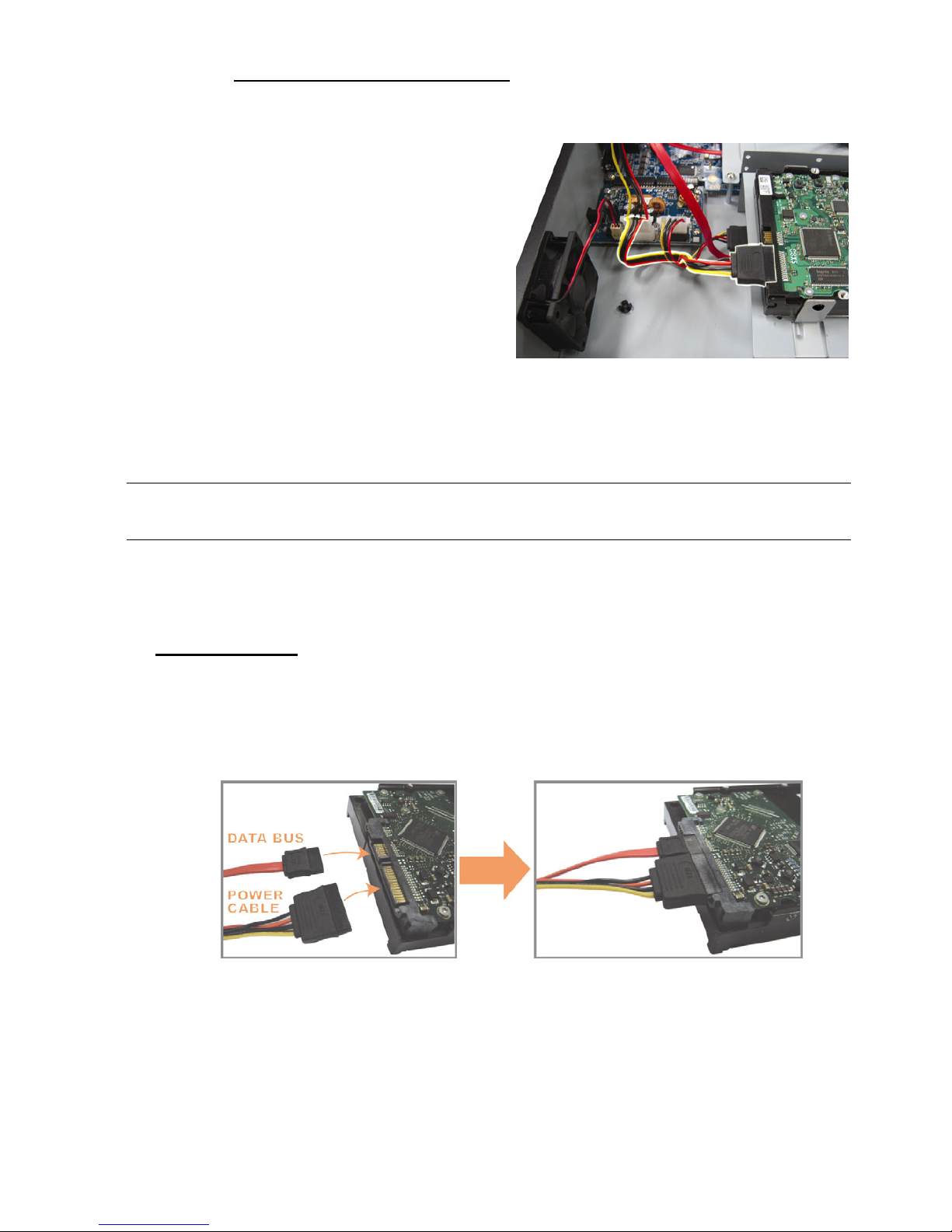
Step2: There are two HDD brackets
for this DVR as indicated on
the right picture.
2-1 To install on the first bracket
Remove the bracket, and align
the screw holes of the bracket
with the HDD’s screw holes. Make
sure the PCB side of the HDD is
facing up.
Fasten the HDD to the bracket,
and connect the power connector
and data bus connector to the
HDD. Then, replace the bracket to
DVR.
Page 11
CONNECTION AND SETUP
6
2-2 To install on the second bracket
Connect the power connector and
data bus connector to the HDD.
When connecting the power
cable, make sure the cable is
passed through the power cable
of DVD writer. This is to prevent
the HDD power cable from
interfering with the fan spinning.
Align the screw holes of the
bracket with the HDD’s screw
holes. Make sure the PCB side of
the HDD is facing up. Then,
fasten the HDD to the bracket.
Note: For DVD writer installation, please refer to “APPENDIX 7 DVD WRITER
INSTALLATION” at page 63.
Step3: Close the upper cover of the DVR, and fasten all the screws you loosened in
Step1.
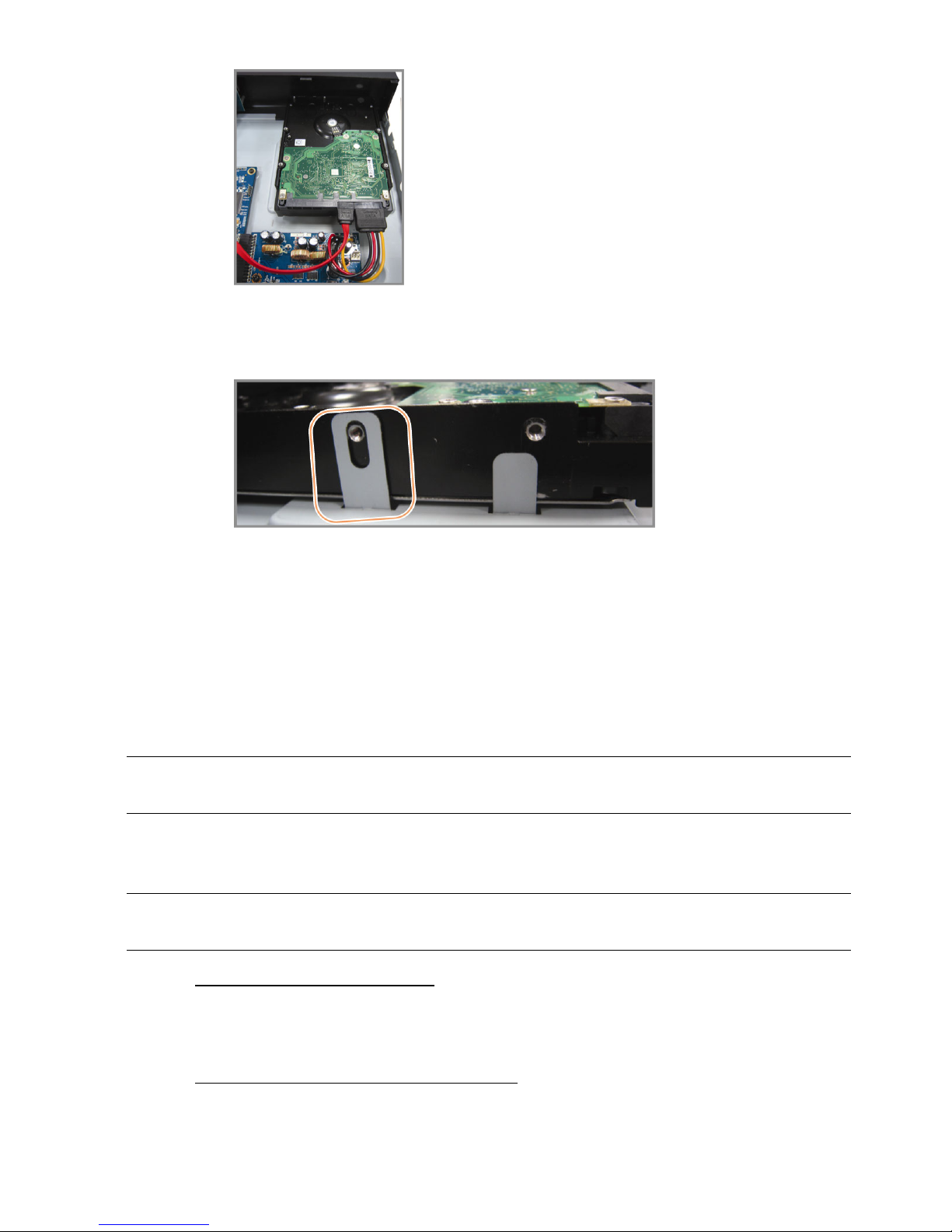
For 1-HDD Model
Step1: Loose the screws on the upper cover and remove it from the DVR. Find the two
HDD brackets located on the DVR base.
Step2: Get a compatible HDD, and connect it to the power connector and data bus
connector.
Step3: Make sure the PCB side is facing up, and place the HDD between the HDD
brackets on the DVR base as shown below.
Make sure the other side of the HDD is contacted with the DVR base for
heat conduction.
Page 12
CONNECTION AND SETUP
7
Step4: Align the screw hole on the each bracket with the screw hole on the each side of
the HDD as shown below, and fix the HDD to the bracket with a HDD screw
supplied.
Step5: Close the upper cover of the DVR, and fasten all the screws you loosened in Step 1.
2.2 Camera Connection
The cameras must be connected and power-supplied before the DVR is powered on.
Connect the camera with the indicated power supply. Then, connect the camera video
output to the DVR video input port with a coaxial cable or RCA cable with BNC
connectors.
Note: For detailed DVR video input ports, please refer to “1.3 Rear Panel” at page
3.
2.2.1 Normal Camera Connection
Note: For detailed camera installation and connection, please refer to its own user
manual.
1) Connecting to DVR video input
Connect the camera video output to the DVR video input port with a coaxial cable or
RCA line with BNC connector.
2) Connecting to DVR audio input (Optional)
Connect the camera audio output to the DVR audio input port with a coaxial cable or
RCA cable with BNC connectors.
Page 13
CONNECTION AND SETUP
8
3) Connecting to power
Connect the camera with indicated power supply and make sure it’s power-supplied.
2.2.2 PTZ Camera Connection (For Selected Models Only)
The following description is taking our brand’s PTZ camera as an example.
For DVR setting to control the PTZ camera, please refer to “5.5 PTZ Camera Setting” at
page 26. For detailed PTZ camera control and operation, please refer to its own user
manual.
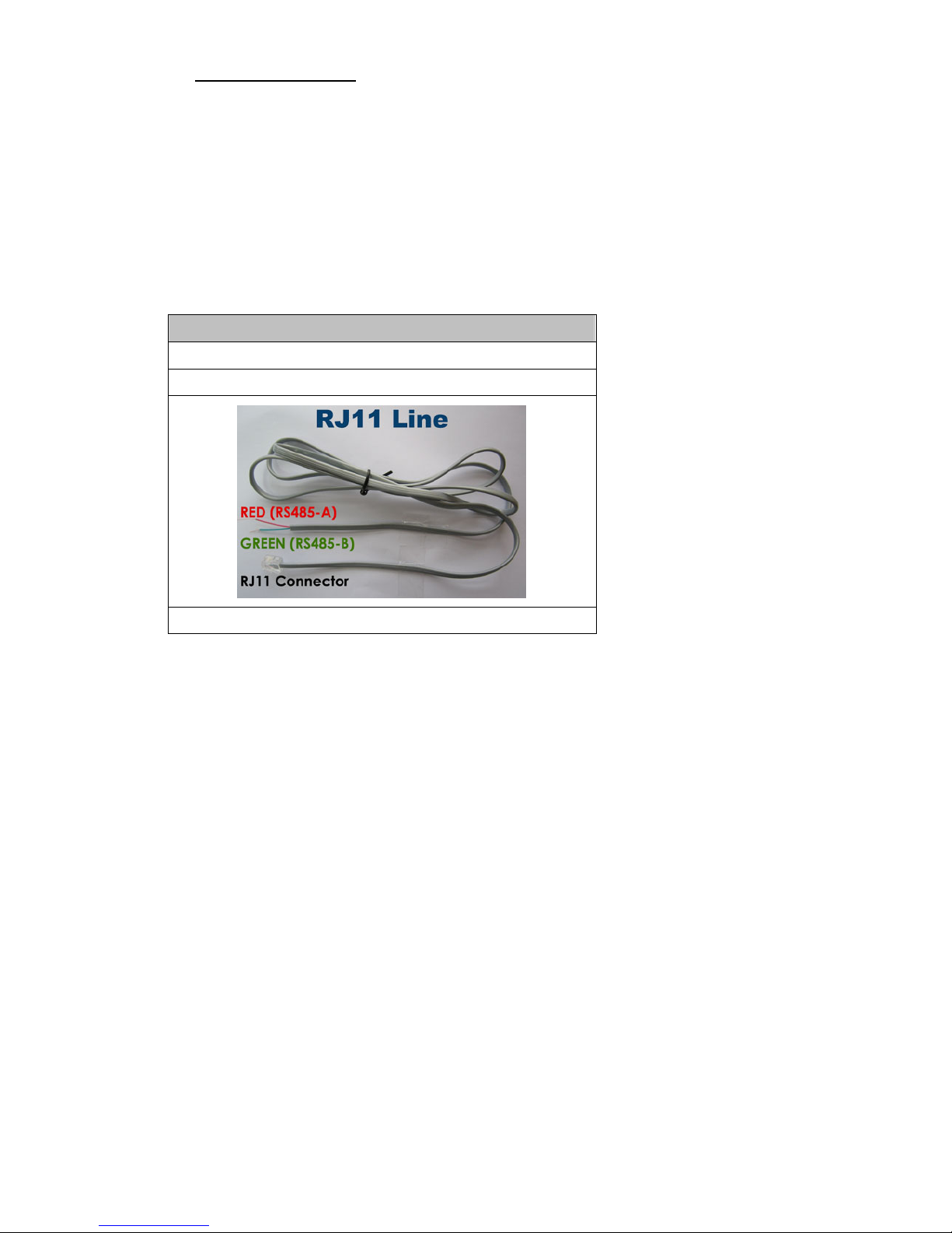
RJ11 cable
RS485-A: Red wire
RS485-B: Green wire
The RJ11 cable is not supplied in the sales package.
STEP 1: Get a RJ11 cable with the proper length to your connection.
Different RJ11 connector may have different wire layout, so the connection
might be different. If you cannot control the DVR after connection, please
reverse the RJ11 cable connection with the DVR.
STEP 2: Remove one end of the insulating coating of the RJ11 cable.
Remove one end of the insulating coating of the RJ11 cable to find the
RS485-A and the RS485-B wires, and remove the insulating coating to reveal
the naked wires for further connection.
STEP 3: Twist the RS485-A and RS485-B wires of the RJ11 cable and the speed
dome camera together.
Twist the RS485-A (red) and RS485-B (green) wires of the RJ11 cable to the
RS485-A (brown) and RS485-B (orange) wires of the speed dome camera. To
protect the naked wires, use the insulation tape to cover on the twisted wires.
STEP 4: Connect the other end of the RJ11 cable to DVR.
Solder the RS485-A (red) and RS485-B (green) wires of the RJ11 cable to the
corresponding pins on the solder side of the optional D-Sub connector.
Page 14

CONNECTION AND SETUP
9
For DVR PIN configuration, please refer to “APPENDIX 6 PIN
CONFIGURATION” at page 60. For connection details, please check with your
installer.
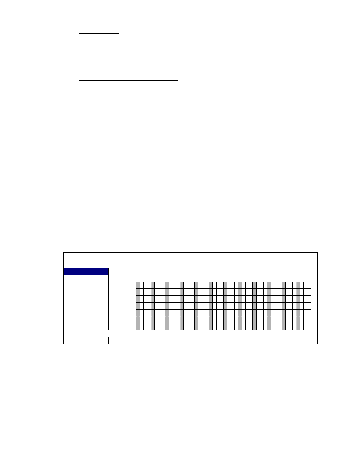
STEP 5: Set the speed dome camera at the DVR side.
Go to “ADVANCE CONFIG” l “REMOTE” to set the speed dome camera.
a) Select the device to “PTZ”.
b) Set the ID to the value the same as the one set in the speed dome camera.
The default ID of the camera is 000.
c) Select the protocol to “NORMAL”.
d) Set the baud rate to the value the same as the one set in the speed dome
camera. The default baud rate of the camera is 2400.
ADVANCE CONFIG
CA N E R A CH1 CH2 CH3 CH4 CH5 CH6 CH7 CH8 CH9 CH10 CH11 W
X
DETECTION DEVICE PTZ
ALERT ID 000
NETWORK PROTOCOL NORMAL
DISPLAY RATE 2400
RECORD
REMOTE
EXIT
2.3 DVR Power On
This device should be operated only with the type of power source indicated on the
manufacturer’s label. Connect the indicated AC power cord to the power adapter, and
plug into an electrical outlet. The power LED will be on.
Note: Before the DVR is powered on, make sure the cameras are connected and
power-supplied for the detection of the camera video system to be correct,
and check the monitor (either LCD or CRT monitor) is connected to the DVR
before the DVR is powered on for correct video output detection.
Note: To ensure that your DVR works constantly and properly, it's recommended
to use an UPS, Uninterruptible Power Supply (Optional), for continuously
operation.
Page 15
CONNECTION AND SETUP
10
2.4 Date and Time Setting
Before operating your DVR, please set the date and time on your DVR FIRST.
Note: Please DO NOT change the date or time of your DVR after the recording
function is activated. Otherwise, the recorded data will be disordered and
you will not be able to find the recorded file to backup by time search. If
users change the date or time accidentally when the recording function is
activated, it’s recommended to clear all HDD data, and start recording
again.
Note: For the first time to use the DVR, please power it on for at least 48 hours
continuously after the date & time is set correctly. It helps to prevent DVR
time from resetting after the disconnecting of DVR power. If the DVR time
resets after the disconnecting of DVR power, for example, caused by a
power outage, the battery might run out and please replace the battery as
described in “APPENDIX 5 DVR BATTERY REPLACEMENT” at page 59.
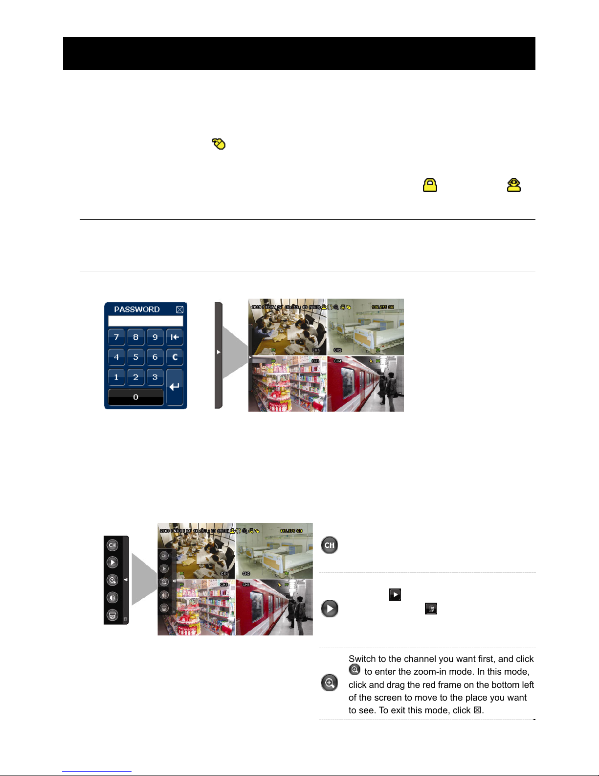
Right-click to enter the DVR password with the password keypad. The default
administrator password is 0000. The status will be changed from (key lock) to
(administrator). Then, right-click to show the main menu, and select “QUICK START”
“TIME SETUP” to set the date & time.
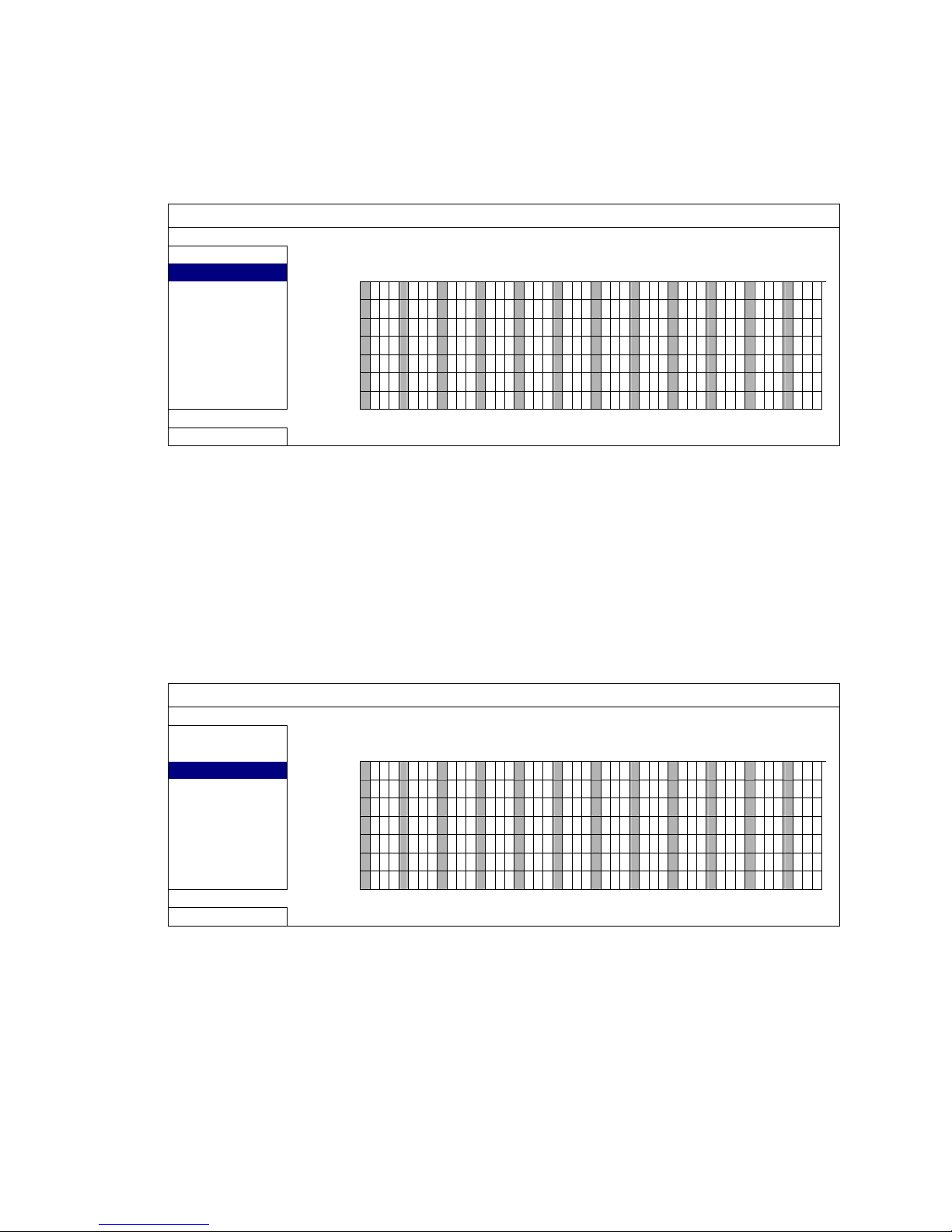
QUICK START
GENERAL
DATE 2009 / NOV / 17
TIME SETUP
TIME 15 : 35 : 53
EXIT
2.5 Clear Hard Disk
It’s recommended to clear all data in the hard disk for the first time to user this DVR to
ensure the recorded data are not mixed with other data previously saved in the same
hard disk.
Right-click to show the main menu, and select “SYSTEM” “SYSTEM INFO”
“CLEAR HDD”. The DVR will reboot when HDD data are cleared.
Page 16

CONNECTION AND SETUP
11
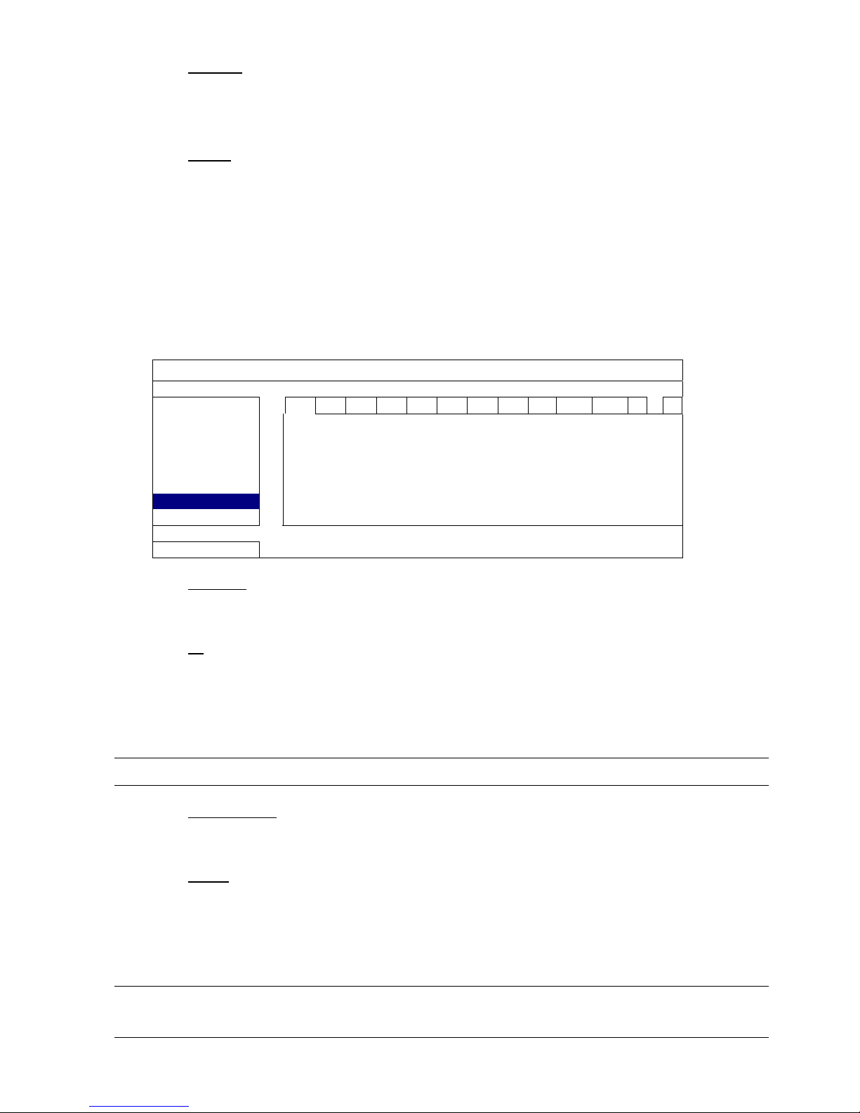
SYSTEM
TOOLS
BAUD RATE 2400
SYSTEM INFO
HOST ID 000
USB BACKUP
R.E.T.R (For Selected Models Only) 5
DVD BACKUP
AUTO KEY LOCK NEVER
CLEAR HDD HDD-0
RESET DEFAULT SUBMIT
REMOTE CONTROL ID 000
SERIAL TYPE RS485
VIDEO FORMAT NTSC
VERSION 1025-1011-1011-1012
EXIT
2.6 Password Setting
Right-click to show the main menu, and select “SYSTEM” “TOOLS” to change the
DVR password.
There are two user levels: ADMIN & OPERATOR. For details, please refer to “4.4 User
Level Switch” at page 17.
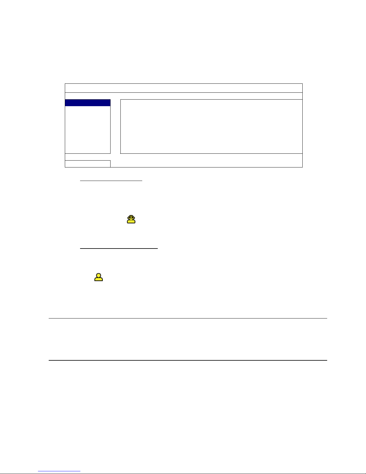
SYSTEM
TOOLS
LANGUAGE ENGLISH
SYSTEM INFO
ADMIN PASSWORD SETUP
USB BACKUP
OPERATOR PASSWORD SETUP
DVD BACKUP
UPGRADE SUBMIT
BACKUP CONFIG (For Selected Models Only) SUBMIT
RESTORE CONFIG (For Selected Models Only) SUBMIT
EXIT
Page 17
GUI DISPLAY WITH USB MOUSE CONTROL
12
3. GUI DISPLAY WITH USB MOUSE CONTROL
3.1 Connect USB Mouse
Connect your USB mouse to one of the USB ports on the DVR front panel, and check if
there’s a mouse icon ( ) on the screen, indicating the USB mouse is detected properly.
Move your mouse to enter the DVR password with the password keypad. The default
administrator password is 0000. The status will be changed from (key lock) to
(administrator), and the quick menu bar appears on the left side of the screen.
Note: There are two user levels for DVR access which can be set in the main menu
“SYSTEM” “TOOLS”. For details, please refer to “4.4 User Level Switch” at
page 17.
Password Input Quick Menu: Close
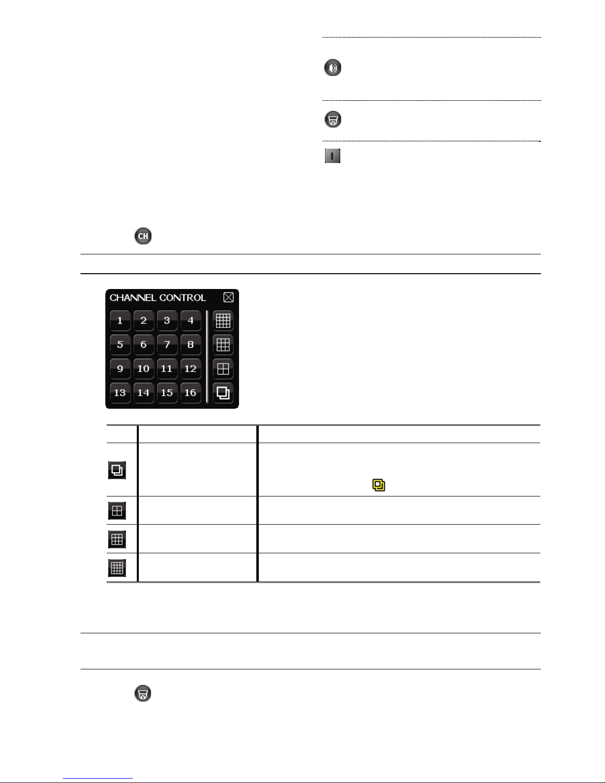
3.2 Quick Menu Bar
Move to the arrow mark to extend the quick menu bar and show the five functions as
follows:
Quick Menu: Open
Click to show the channel switch panel and
select the channel you want. For details,
please refer to “3.2.1 Channel Switch” at
page 13.
Click to display the playback control panel,
and click
to play the latest recorded
video clip, or click
to enter the search list.
For details, please refer to “4.3 Playback” at
page 16.
Switch to the channel you want first, and click
to enter the zoom-in mode. In this mode,
click and drag the red frame on the bottom left
of the screen to move to the place you want
to see. To exit this mode, click 7.
Page 18
GUI DISPLAY WITH USB MOUSE CONTROL
13
Click to select the audio channel you want:
In the live mode, only the live audio channels
can be selected.
In the playback mode, live and playback
audio channels can be selected.
Click to enter the PTZ mode and show the
PTZ camera control panel. For details, please
refer to “3.2.2 PTZ Control Panel” at page 13.
Click to show the power off panel to either
halt or reboot the system.
3.2.1 Channel Switch
Click on the quick menu bar to display the panel as follows:
Note: The buttons available depend on the model you have.
1~16 Video Channel Number
Click to switch to the channel you want in full screen.
Sequence Display
Click to display each channel in full screen one by one starting
from CH1. When the last channel is displayed, it will repeat from
CH1 again.
When this function is on,
will be shown on the status bar.
Quad Display
Press to show the 4-channel display mode.
9-Cut Display
Press to show the 9-channel display mode.
16-Cut Display
Press to show the 16-channel display mode.
3.2.2 PTZ Control Panel (For Selected Models Only)
Note: In the PTZ control mode, hot point is supported to move the camera view to
the specified point after a click.
Click on the quick menu bar to display the panel as follows:
Page 19

GUI DISPLAY WITH USB MOUSE CONTROL
14
Camera Menu
Click to enter the camera main menu.
For details about each camera menu, please refer to its
own user manual.
Enter
Click to confirm your selection / enter the menu.
/ / /
Up / Down / Left /
Right
Click to move your selection up / down / left / right, or
change settings.
/
Zoom in / out max
Click to zoom in on the image to the largest / zoom out
on the image to its original size.
/
Zoom in / out
Click to zoom in / out the image.
/
Focus near / far
Click to adjust the focus of the image.
Auto mode
Click to activate the auto function.
Before using it, you need to assign a specific function
that will be enabled when “AUTO” is clicked. For
details, please refer to the user manual of the PTZ
camera.
Preset point
Click to enter the PTZ preset point you want to see.
3.3 Main Menu
Right-click anywhere on the screen to show the main menu as follows, and right-click
again to exit.
For details about the menu structure, please refer to “APPENDIX 4 MAIN MENU
STRUCTURE” at page 57.
Main Menu
QUICK START
Click to set the status display, image
settings, and date & time.
DATE SETUP
Click to set the date display and
daylight saving.
SYSTEM Click to set the system configurations.
EVENT
INFORMATION
Click to enter the event search menu.
ADVANCE
CONFIG
Click to set CAMERA, DETECTION,
ALERT, NETWORK, DISPLAY,
RECORD and REMOTE.
SCHEDULE
SETTING
Click to set record timer and detection
timer.
Page 20
BASIC OPERATION
15
4. BASIC OPERATION
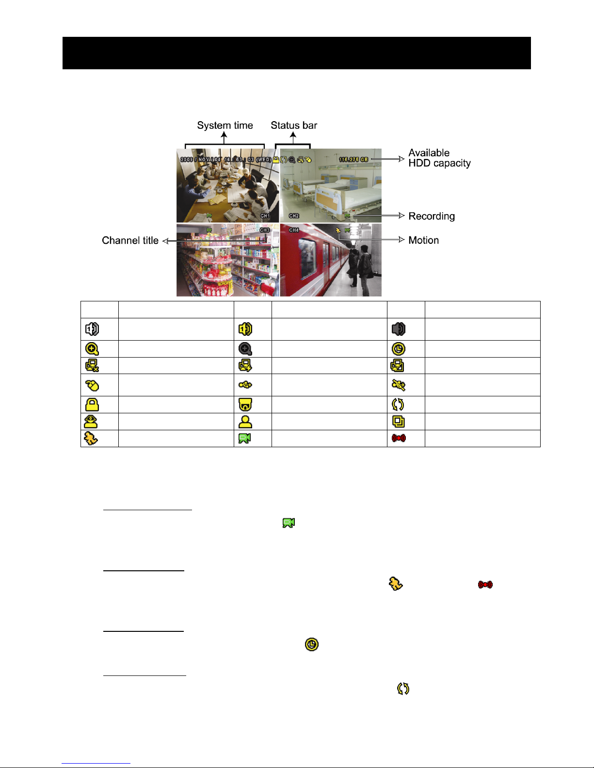
4.1 Live Page
Icon Function Icon Function Icon Function
Live audio channel (1~4)
Playback audio channel
(1~4)
Audio channel off
Digital zoom on
Digital zoom off
Timer recording
Network disconnected
Internet connected
LAN connected
USB mouse connected
USB flash drive / device
connected
No USB device
connected
Key lock
PTZ mode on
HDD overwrite
Administrator
Operator
Sequence
Motion
Recording
Alarm
4.2 Record Icon
1) Manual Recording
By defaults, manual recording is on (
) when the DVR is powered on and a HDD is
installed.
2) Event Recording
When the motion detection or alarm is on, the motion icon (
) or alarm icon ( ) shows
on the screen for any motion or alarm event.
3) Timer Recording
When timer recording is on, you will see “ ” on the screen.
4) HDD Overwritten
Be defaults, the HDD overwritten function is set to ON, and “ ” will be shown on the
screen.
Page 21
BASIC OPERATION
16
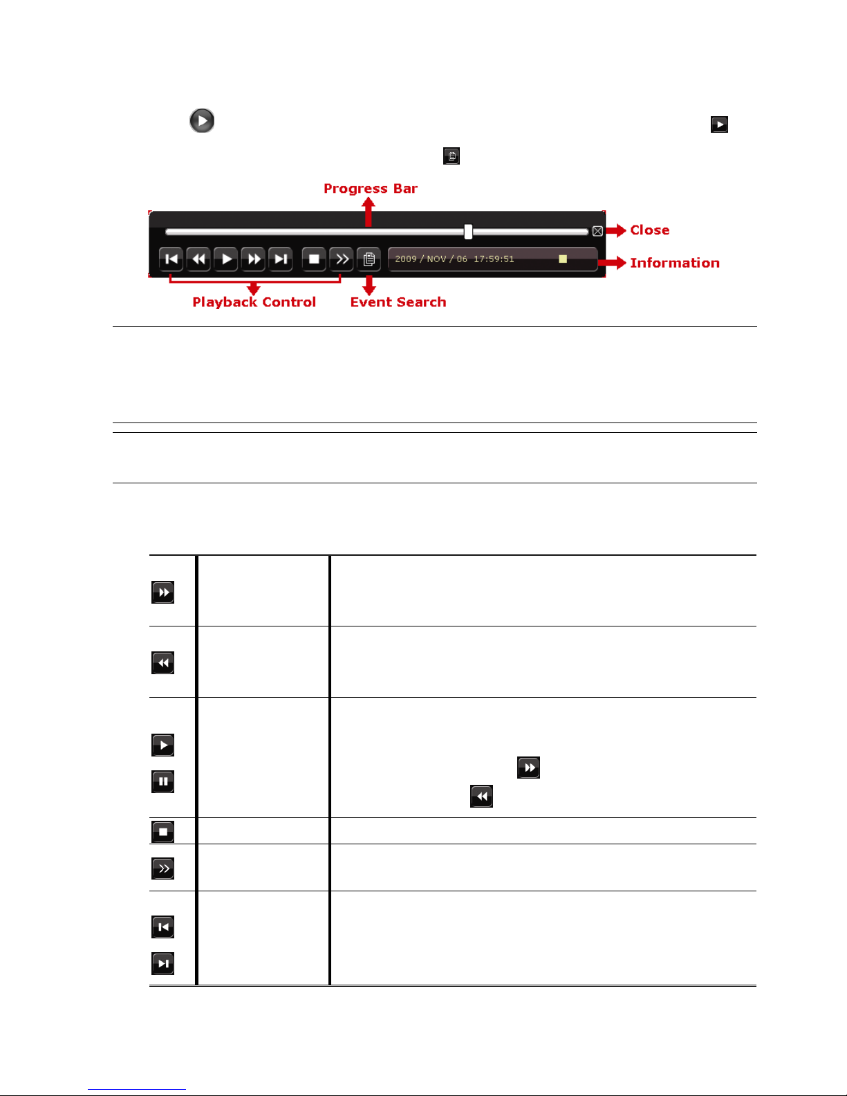
4.3 Playback
Click “ ” on the quick menu bar to display the playback control panel, and click to
play the latest recorded video clip, or click to enter the search list.
Note: There must be at least 8192 images of recorded data for playback to work
properly. If not, the device will stop playback. For example, if the IPS is set
to 30, the recording time should be at least 273 seconds (8192 images / 30
IPS) for the playback to work properly.
Note: During playback, the image size of the recording (FRAME, FIELD or CIF) will
be shown on the screen.
4.3.1 Playback Control
Fast Forward
Increase the speed for fast forward. Click once to get 4X
speed forward and click twice to get 8X speed, etc., and
the maximum speed is 32X.
Fast Rewind
Increase the speed for fast rewind. Click once to get 4X
speed rewind and click twice to get 8X speed, etc., and the
maximum speed is 32X.
/
Play / Pause
Click to play the latest recorded video clip immediately,
and click again to pause.
In the pause mode, click once to get one frame
forward, and click to get one frame rewind.
Stop
Click to stop the video playback.
Slow Playback
Click once to get 1/4X speed playback, and click twice to
get 1/8X speed playback.
/
Previous /
Next Hour
Click to jump to the next / previous time interval in an hour,
for example, 11:00 ~ 12:00 or 14:00 ~ 15:00, and start
playing the earliest event video clip recorded during this
whole hour.
Page 22
BASIC OPERATION
17
4.3.2 Event Search
Click to quickly search the recorded files by event lists: RECORD / MOTION /
ALARM / TIME, or select FULL to show all the event logs.
To quickly search the time you want, select “QUICK SEARCH”. Set the time range you
want, and select “Start” to play the recorded video clip during the specified time.
4.3.3 Audio Playback
In the playback mode, click on the quick menu bar as many times as needed to
select live or playback audio from audio channel 1~4.
Live audio from audio channel 1~4
(indicated in white).
Playback audio from audio channel 1~4
(indicated in yellow).
Audio channel unselected
Note: To make a video backup with audio, make sure the camera which supports
the audio function is connected to the video-in channel and audio-in
channel. For example, the audio data from audio CH1 will be recorded with
the video data from video CH1.
4.4 User Level Switch
In the key lock mode ( ), move your USB mouse to display the password input keypad.
There are two user levels for accessing the DVR: Administrator ( ) & Operator ( ).
When the administrator password is entered, will be shown on the status bar of the
screen and all operations are allowed. The default administrator password is 0000.
When the operator password is entered, will be shown on the status bar of the
screen, and the main menu is NOT allowed to access. The operator user level needs to
be set in the main menu “SYSTEM” “TOOLS”.
To switch between these two user levels, click the current user level icon to switch to the
key lock mode, and move your mouse to show the password input keypad, and enter the
password of the user level you want.
4.5 Video Output Switch (For Selected Models Only)
Some models do not support to have video output simultaneously on a CRT monitor
(connected to “MONITOR”) and LCD monitor (connected to “VGA”).
The default video output setting is “AUTO”, meaning the DVR will automatically detect
Page 23

BASIC OPERATION
18
the video output source. When “VGA” and “MONITOR” are both connected, the default
monitor output is VGA.
To change the video output setting manually:
To force the video output via “MONITOR”, press the left key ◄ on the DVR front panel at
DVR power-on.
To force the video output via “VGA”, press the right key ► on the DVR front panel at DVR
power-on.
The setting is changed when you hear a short beep sound.
OR:
When the DVR is powered on and initialized, right-click to show the main menu, and
select “ADVANCE CONFIG” “DISPLAY” “DISPLAY OUTPUT PATH”.
Select “VGA” to switch to the connected LCD monitor, or “COMPOSITE” to switch to the
connected CRT monitor. The DVR will then reboot for the change to take effect.
ADVANCE CONFIG
CAMERA
DE-INTERLACE
(For Selected Models Only) OFF
DETECTION
FULL SCREEN DURATION 03
ALERT
QUAD SCREEN DURATION
(For Selected Models Only) 03
NETWORK
DWELL SCREEN DURATION
(For Selected Models Only) 03
DISPLAY
DISPLAY COVERT ON
RECORD
HDD DISPLAY MODE HDD SIZE
REMOTE
DISPLAY OUTPUT PATH
(For Selected Models Only) AUTO
ALPHA BLENDING
(For Selected Models Only) 200
EXIT
Page 24
FREQUENTLY-USED FUNCTIONS
19
5. FREQUENTLY-USED FUNCTIONS
5.1 Quick Search
Press “LIST” on the DVR front panel to enter the time search menu as follows:
EVENT INFORMATION
HARD DISK ALL HDD
CHANNEL 01 02 03 04
05 06 07 08
09 10 11 12
13 14 15 16
W 2009 X NOV
SUN MON TUE WED THU FRI SAT
1 2 3 4 5 6 7
8 9 10 11 12 13 14
15 16 17 18 19 20 21
22 23 24 25 26 27 28
29 30
00 06 12 18 24
15 : 20
SUBMIT
Step1: Select the hard disk and channel including the video data you want to search.
Step2: Select the month including the video data you want to search from the calendar,
and the date with recorded data will be highlighted.
Step3: Select the date you want from the calendar, and the time with recorded data will
be highlighted from the time scale bar.
Step4: To immediately play the video clip, click “SUBMIT”.
To choose the start time for video playback, move your mouse cursor to the
highlighted time, and click to confirm the time when the time display below is the
time you want. The video playback is activated right away when you confirm the
time.
Page 25

FREQUENTLY-USED FUNCTIONS
20
5.2 Record
5.2.1 Quick record setting
Right-click to display the main menu, and select “QUICK START” “GENERAL”.
QUICK START
GENERAL
CHANNEL TITLE ON
TIME SETUP
EVENT STATUS ON
DATE DISPLAY ON
IMAGE SIZE CIF
QUALITY SUPER BEST
I.P.S. 120
EXIT
1) IMAGE SIZE
Select one of the image sizes: FRAME, FIELD or CIF.
2) QUALITY
Select one of the 4 quality options: SUPER BEST, BEST, HIGH & NORMAL.
3) I.P.S.
Select the images per second for MANUAL RECORD.
OR
Right-click to display the main menu, and select “QUICK START” “GENERAL”
“RECORD CONFIGURATION”.
Click “SETUP” to enter the setting page individually for manual record, event record and
timer record.
QUICK START
GENERAL
CHANNEL TITLE ON
TIME SETUP
EVENT STATUS ON
DATE DISPLAY ON
RECORD CONFIGURATION SETUP
EXIT
Page 26

FREQUENTLY-USED FUNCTIONS
21
a) Select the record type you want to set.
b) In “CHANNEL”, select “ALL” to apply the changes here to all channels.
QUICK START
MANUAL EVENT TIMER
CHANNEL IMAGE SIZE I.P.S. QUALITY
ALL CIF 100 SUPER BEST
EXIT
Or, select “BY CHANNEL” to set the image size, image per second & image quality
individually for each channel.
QUICK START
MANUAL EVENT TIMER
CHANNEL IMAGE SIZE I.P.S. QUALITY LOCK
CH1 CIF 25 SUPER BEST
CH2 CIF 25 SUPER BEST
CH3 CIF 6 HIGH
CH4 FIELD 25 SUPER BEST
AVAILABLE IPS: CIF 69 / FIELD 34 / FRAME 17
APPLY EXIT
Note: The allocatable IPS (image per second) in each image size for a DVR is fixed.
When allocating IPS to each channel, select “LOCK” to remind you of the
remaining IPS in each image size available for the rest of the channels.
Page 27

FREQUENTLY-USED FUNCTIONS
22
5.2.2 Detailed record setting
Right-click to display the main menu, and select “ADVANCE CONFIG” “RECORD”.
Note: Please DO NOT change the date or time of your DVR after the recording
function is activated. Otherwise, the recorded data will be disordered and
you will not be able to find the recorded file to backup by time search. If
users change the date or time accidentally when the recording function is
activated, it’s recommended to clear all HDD data, and start recording
again.
ADVANCE CONFIG
CAMERA
MANUAL RECORD ENABLE ON
DETECTION
EVENT RECORD ENABLE ON
ALERT
TIMER RECORD ENABLE ON
NETWORK
EVENT RECORD IPS (For Selected Models Only) 120
DISPLAY
TIMER RECORD IPS (For Selected Models Only) 120
RECORD
PRE-ALARM RECORD (For Selected Models Only) ON
REMOTE
OVERWRITE ON
EVENT RECORD ALL CHANNEL OFF
KEEP DATA LIMIT (DAYS) OFF
RECORD CONFIGURATION (For Selected Models Only) SUBMIT
EXIT
1) MANUAL RECORD ENABLE
Set the manual recording function on / off.
2) EVENT RECORD ENABLE
Set the event recording function on / off.
3) TIMER RECORD ENABLE
Set the timer recording function on / off.
4) EVENT RECORD IPS
(For Selected Models Only)
Select the images per second for EVENT RECORD (Recording that is triggered by
alarm or motion).
5) TIMER RECORD IPS
(For Selected Models Only)
Select the images per second for TIMER RECORD (Recording that is activated
according to the scheduled time).
6) PRE-ALARM RECORD
(For Selected Models Only)
Select to enable or disable the pre-alarm function (ON / OFF).
When pre-alarm and event recording functions are both activated, the DVR will
record 8MB data before an alarm / motion event is triggered.
Page 28
FREQUENTLY-USED FUNCTIONS
23
7) OVERWRITE
Select “ON” to overwrite previous recorded data in your HDD when the HDD is full.
When this function is on and the HDD is full, the DVR will clear 8GB data from the
oldest for continuous recording without notice.
8) EVENT RECORD ALL CHANNEL
Select to record all channels (ON) or record the channel with an event only (OFF)
for any event.
9) KEEP DATA LIMIT (DAYS)
Assign the maximum recording days from 01 to 31 after which all the recorded data
will be removed, or select “OFF” to disable this function.
10) RECORD CONFIGURATION
Please refer to “5.2.1 Quick record setting”.
5.3 Schedule Setting
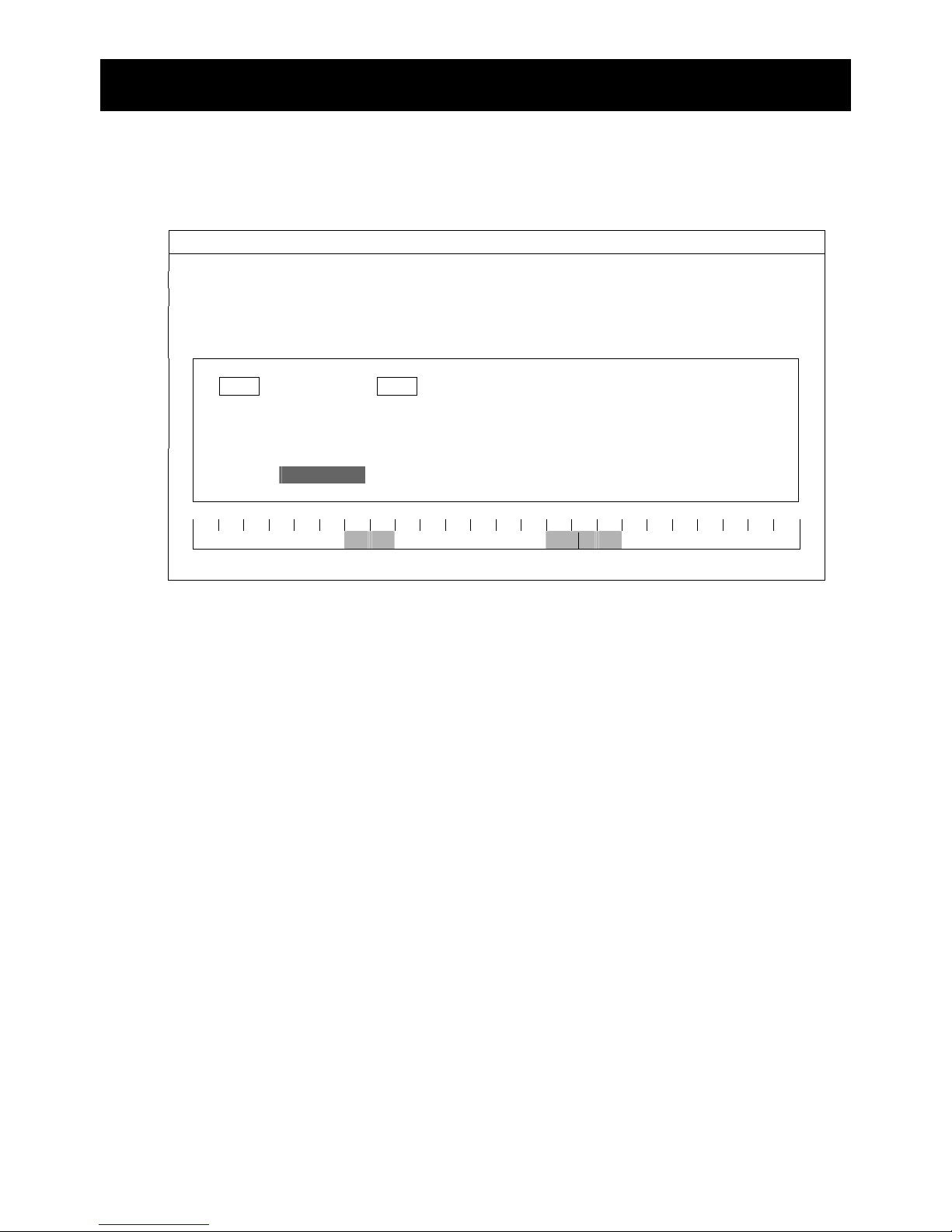
Right-click to display the main menu, and select “SCHEDULE SETTING”.
5.3.1 Record Timer
Click “RECORD”. In “RECORD TIMER”, select “ON” to enable record timer, and select
the day and time for this function.
SCHEDULE SETTING
RECORD
RECORD TIMER ON
DETECTION
0 2 4 6 8 10 12 14 16 18 20 22 24
ALARM
SUN
MON
TUE
WED
THU
FRI
SAT
EXIT
X axis
0 ~ 24 hours. Each time bar is 30 minutes.
Y axis
Monday ~ Sunday.
Page 29
FREQUENTLY-USED FUNCTIONS
24
5.3.2 Detection Timer
Click “DETECTION”. In “DETECTION TIMER”, select “ON” to enable record timer, and
select the day and time for this function.
SCHEDULE SETTING
RECORD
DETECTION TIMER ON
DETECTION
0 2 4 6 8 10 12 14 16 18 20 22 24
ALARM
SUN
MON
TUE
WED
THU
FRI
SAT
EXIT
X axis
0 ~ 24 hours. Each time bar is 20 minutes.
Y axis
Monday ~ Sunday.
5.3.3 Alarm Timer
Click “ALARM”. In “ALARM TIMER”, select “ON” to enable record timer, and select the
day and time for this function.
SCHEDULE SETTING
RECORD
ALARM TIMER ON
DETECTION
0 2 4 6 8 10 12 14 16 18 20 22 24
ALARM
SUN
MON
TUE
WED
THU
FRI
SAT
EXIT
X axis
0 ~ 24 hours. Each time bar is 20 minutes.
Y axis
Monday ~ Sunday.
Page 30

FREQUENTLY-USED FUNCTIONS
25
5.4 Detection Setting
Right-click to display the main menu, and select “ADVANCE CONFIG” “DETECTION”.
ADVANCE CONFIG
C A N E R A CH1 CH2 CH3 CH4 CH5 CH6 CH7 CH8 CH9 CH10 CH11 W X
DETECTION LS (For Selected Models Only) 07
ALERT SS (For Selected Models Only) 03
NETWORK TS (For Selected Models Only) 02
DETECT OFF
DISPLAY ALARM OFF
RECORD AREA EDIT
REMOTE
EXIT
1) LS (Level of Sensitivity) (For Selected Models Only)
“LS” is to set the sensitivity of comparing two different images. The smaller the
value is, the higher sensitivity for motion detection. The highest sensitivity setting is
00, and the lowest sensitivity setting is 15. The default value is 07.
2) SS (Spatial Sensitivity) (For Selected Models Only)
“SS” is to set the sensitivity for detecting the size of one object (the number of the
grids) on the screen. The smaller the value is, the higher sensitivity for motion
detection.
The highest sensitivity setting is 00, and the lowest sensitivity setting is 15. The
default setting is 03.
Note: The default setting of SS is 03, which means once an object is detected
more than 3 grids, the system will get triggered. So the value of SS must be
less than the number of grids that you set up for the motion detection area.
3) TS (Time of Sensitivity) (For Selected Models Only)
“TS” is to set the sensitivity regarding how long one object stays in the detection
area and triggers the recording. The smaller the value is, the higher sensitivity for
motion detection.
The highest sensitivity setting is 00, and the lowest sensitivity setting is 15. The
default setting is 02.
4) DETECT
Based on the model you have:
Select if you want to activate the motion detection function for the selected channel
(ON/OFF).
Or,
Select the detection sensitivity to LOW / NORMAL / HIGH, or disable the motion
detection function for the selected channel (OFF).
Page 31
FREQUENTLY-USED FUNCTIONS
26
5) ALARM
Select N.C./ N.O depending on your installation need. The default alarm value is
OFF.
6) AREA
Click “EDIT” to set the motion detection area.
There are 16 × 12 grids per camera for all channels. Pink blocks represent the area
that is not being detected while the transparent blocks are the area under
detection.
5.5 PTZ Camera Setting (For Selected Models Only)
Right-click to display the main menu, and select “ADVANCE CONFIG” “REMOTE”.
ADVANCE CONFIG
C A N E R A CH1 CH2 CH3 CH4 CH5 CH6 CH7 CH8 CH9 CH10 CH11 W X
DETECTION DEVICE PTZ
ALERT ID 00
NETWORK PROTOCOL NORMAL
DISPLAY RATE 2400
RECORD
REMOTE
EXIT
1) DEVICE
For the PTZ camera, select “PTZ”.
2) ID
Click the current value to set the ID number (0 ~ 255) for the connected PTZ
camera if necessary.
Make sure the ID setting of the camera is the same as the setting here, or the DVR
will not be able to control the device.
Note: To know the default ID of the PTZ camera, please refer to its user manual.
3) PROTOCOL
Select NORMAL (our protocol), P-D (PELCO-D) or P-P (PELCO-P) protocol.
4) RATE
Select the baud rate for the connected PTZ camera (2400 / 4800 / 9600 / 19200 /
57600 / 115200).
Make sure the baud rate setting of the camera is the same as the setting here, or
the DVR will not be able to control the device.
Note: To know the default baud rate of the PTZ camera, please refer to its user
manual.
Page 32
FREQUENTLY-USED FUNCTIONS
27
5.6 System Setting
5.6.1 Password Setting
Right-click to display the main menu, and select “SYSTEM” “TOOLS”.
SYSTEM
TOOLS
LANGUAGE ENGLISH
SYSTEM INFO
ADMIN PASSWORD SETUP
USB BACKUP
OPERATOR PASSWORD SETUP
DVD BACKUP
UPGRADE SUBMIT
BACKUP CONFIG (For Selected Models Only) SUBMIT
RESTORE CONFIG (For Selected Models Only) SUBMIT
EXIT
1) ADMIN PASSWORD
Click “SETUP” to change the administrator password. The default administrator
password is 0000.
When you’re prompted to enter the DVR password, enter the administrator
password, and will be shown on the status bar of the screen and all operations
are allowed.
2) OPERATOR PASSWORD
Click “SETUP” to set or change the operator password. .
When you’re prompted to enter the DVR password, enter the operator password,
and
will be shown on the status bar of the screen and the main menu is NOT
allowed to access.
5.6.2 System Upgrade
Note: DVR system upgrade might cause all HDD data cleared when your current
system version is too old from the latest version. Therefore, before
upgrading the DVR system, check your current firmware version with your
installer or distributor, and make video backup if necessary.
Right-click to display the main menu, and select “SYSTEM” “TOOLS” “UPGRADE”.
Save the upgrade files obtained from your installer or distributor in a compatible USB
flash drive, and insert it into the USB port at the front panel.
Then, click “SUBMIT” to start upgrading.
Page 33

FREQUENTLY-USED FUNCTIONS
28
Note: Before using the USB flash drive, please use your PC to format the USB
flash drive to FAT32 format first. For the list of compatible USB flash drives,
please refer to “APPENDIX 2 COMPATIBLE USB FLASH DRIVE LIST” at page
55.
5.6.3 Backup & Restore Configurations
Right-click to display the main menu, and select “SYSTEM” “TOOLS” “BACKUP
CONFIG” or “RESTORE CONFIG”.
These two functions allows users to keep the current configurations after DVR upgrade,
or copy one DVR configurations to another DVR if necessary.
Insert a compatible USB flash drive into the USB port before upgrading DVR, and select
“SUBMIT” in “BACKUP CONFIG” to copy the current DVR configurations to a file
“System.bin” and save to your USB flash drive.
To restore DVR configurations after upgrading DVR, insert the USB flash drive including
“System.bin” to the USB port, and select “SUBMIT” in “RESTORE CONFIG”.
5.6.4 Video Backup
Right-click to display the main menu, and select “SYSTEM” “USB BACKUP” or “DVD
BACKUP”.
Note: DVD BACKUP is only available for selected models. Please check the
specifications of your DVR model for details.
Insert a compatible USB flash drive to the USB port at the front panel, or press to
eject the DVD writer and place a DVD-ROM or CD-ROM to it.
Note: Before using the USB flash drive, please use your PC to format the USB
flash drive to FAT32 format first. For the list of compatible USB flash drives,
please refer to “APPENDIX 2 COMPATIBLE USB FLASH DRIVE LIST” at page
55.
Note: For the compatible CD- / DVD-ROM list, please refer to “APPENDIX 8 DVD-
/ CD-ROM COMPATIBLE LIST” at page 64.
Page 34
FREQUENTLY-USED FUNCTIONS
29
SYSTEM
TOOLS
START DATE 2009/NOV/19
SYSTEM INFO
START TIME 08:30:21
USB BACKUP
END DATE 2009/NOV/19
DVD BACKUP
END TIME 17:59:29
CHANNEL 01 02 03 04
05 06 07 08
09 10 11 12
13 14 15 16
HARD DISK ALL HDD
BACKUP SUBMIT
REQUIRE SIZE: 554MB SUBMIT
EXIT
AVAILABLE SIZE: 3788.0MB
1) START DATE / START TIME
Select the start date & time.
2) END DATE / TIME
Select the end date & time.
3) CHANNEL
Click to select the channel(s).
4) HARD DISK
Select the hard disk containing the video data you need or “ALL HDD”.
5) BACKUP
Click “SUBMIT” to start backup.
6) REQUIRE SIZE
To know the size of the expected backup video before backup, click
“SUBMIT” to start calculating.
Backup File Playback
During the backup process, a file player installer “PLAYER.EXE” will also be
copied into your USB flash drive or disk, and you will see the message
“CHECK PLAYER” shown on the screen.
Note: The maximum number of backup files in the CD-ROM or DVD-ROM is 41.
Insert your USB flash drive or place the CD or DVD into the DVD-ROM drive
of your PC. Install the file player “PLAYER.EXE”, and double click a backup
file to play it directly in your PC and see if the backup is successful.
Note: The supported PC operating systems are Windows 7, Vista, XP & 2000.
Page 35

FREQUENTLY-USED FUNCTIONS
30
5.6.5 Clear All HDD Data
Right-click to show the main menu, and select “SYSTEM” “SYSTEM INFO”
“CLEAR HDD”.
SYSTEM
TOOLS
BAUD RATE 2400
SYSTEM INFO
HOST ID 000
USB BACKUP
R.E.T.R (For Selected Models Only) 5
DVD BACKUP
AUTO KEY LOCK NEVER
CLEAR HDD HDD-0
RESET DEFAULT SUBMIT
REMOTE CONTROL ID 000
SERIAL TYPE RS485
VIDEO FORMAT NTSC
VERSION 1010-1005-1006-1007
EXIT
Select the HDD you want to clear, and click “YES” to confirm or “NO” to cancel.
It’s recommended to clear all data in the hard disk when:
It’s the first time to use this DVR to ensure the recorded data are not mixed with other data
previously saved in the same hard disk.
DVR date and time are changed accidentally when the recording function is activated.
Otherwise, the recorded data will be disordered and you will not be able to find the
recorded file to backup by time search.
5.7 Network
The description below is only for STATIC network type. For PPPOE and DHCP settings,
you need to set from “Video Viewer”.
For details, please download the extended user manual for “Video Viewer” from
http://www.surveillance-download.com/user/CMS.pdf
.
STATIC
ADVANCE CONFIG
CANERA
NETWORK TYPE STATIC
DETECTION
IP 192.168.001.010
ALERT
GATEWAY 192.168.001.254
NETWORK
NETMASK 255.255.255.000
DISPLAY
PRIMARY DNS 168.095.001.001
RECORD
SECONDARY DNS 139.175.055.244
REMOTE
PORT 0080
SAVE NETWORK SETTING APPLY
EXIT
Page 36

FREQUENTLY-USED FUNCTIONS
31
1) NETWORK TYPE
Select the network type as STATIC and set all the information needed in the DVR.
3) NETWORK INFORMATION (IP / GATEWAY / NETMASK)
Key in all the network information obtained from your ISP (Internet Service
Provider).
4) DNS (PRIMARY DNS / SECONDARY DNS)
Key in the IP address of the domain name server obtained from your ISP (Internet
Service Provider).
5) PORT
The valid number ranges from 1 to 9999. The default value is 80. Typically, the
TCP port used by HTTP is 80. However in some cases, it is better to change this
port number for added flexibility or security.
6) SAVE NETWORK SETTING
Click “APPLY” to confirm the settings.
5.8 Event Notifications (For Selected Models Only)
It’s available to set event notifications to FTP / E-Mail from this DVR.
Note: This function requires Internet access. Please make sure your Internet
access is available for this function to work properly.
5.8.1 FTP
When this function is enabled and an event occurs, a html file including a link will be sent
to the specified FTP site. Click the link to access to this DVR and check the event
recording.
ADVANCE CONFIG
CANERA
NETWORK SNTP FTP E-MAIL
DETECTION
FTP ALERT ON
ALERT
USER NAME MANAGER
NETWORK
PASSWORD ●●●●●●
DISPLAY
SERVER 192.168.2.32
RECORD
PORT 0021
REMOTE
DIRECTORY UPLOAD
EXIT
Page 37

FREQUENTLY-USED FUNCTIONS
32
5.8.2 E-MAIL
When this function is enabled and an event occurs, a html file including a link will be sent
to the specified E-mail address. Click the link to access to this DVR and check the event
recording.
ADVANCE CONFIG
CANERA
NETWORK SNTP FTP E-MAIL
DETECTION
E-MAIL ALERT ON
ALERT
SMTP SERVER SNTP.GMAIL.COM
NETWORK
PORT 465
DISPLAY
MAIL FROM MANAGER
RECORD
SSL ENCRYPTION ON
REMOTE
VERIFY PASSWORD ON
USER NAME MANAGER
PASSWORD ●●●●●●
RECEIVER SETUP
EXIT
Page 38

REMOTE OPERATION
33
6. REMOTE OPERATION
You can also control the DVR remotely via the supplied licensed software “Video Viewer”,
Internet Explorer web browser, and Apple’s QuickTime player.
6.1 Supplied Licensed Software
The sections below describe frequently-used functions of the Video Viewer. For details
about this software and network settings, please download its extended user manual
from the following link:
http://www.surveillance-download.com/user/CMS.pdf
6.1.1 Installation & Network Connection
1) Install the software
Step1: Place the supplied CD into your CD-ROM or DVD-ROM drive. The program
will be automatically run.
Step2: Click “Download The Latest Version” under “Licensed Software AP” to
download the latest version of Video Viewer from the Internet.
Step3: Follow the on-screen instructions to finish the installation. When the
installation is completed, a shortcut icon “ ” will be placed on your PC
desktop.
2) Network Connection
LLooccaall CCoonnnneeccttiioonn ((vviiaa LLAANN))
LAN is used when it’s the first time to remotely access the DVR and you
need to configure the network setting of your DVR based on your network
type in advance.
a) Connect the DVR to your PC via a RJ45 network cable. The default DVR values
are as follows:
Item Default Value
IP address 192.168.1.10
User name admin
Password admin
Port 80
b) Set the PC’s IP address as “192.168.1.XXX” (1~255, except 10) in order to
make the PC and DVR under the same domain.
c) Double-click “ ” icon on your PC desktop to enter the control panel. By
defaults, the “Address Book” panel will be displayed on the right side of the
Page 39

REMOTE OPERATION
34
control panel.
d) Click “ ” “ ” to key in the default IP address, user name, password,
and port number of the DVR you intend to connect.
OR
Click “ ” “ ” to search the available IP address(es) of other DVR(s)
under the same domain as your PC’s IP address. The found address(es) will be
listed, and can be added into the address book by clicking “ ”.
e) Double-click the IP address you just added into the address book to log in.
RReemmoottee CCoonnnneeccttiioonn ((vviiaa IInntteerrnneett))
When the network configuration of your DVR is completed, you can access your
DVR remotely via Internet.
a) Double-click “ ” icon on your PC desktop to enter the control panel. By
defaults, the “Address Book” panel will be displayed on the right side of the
control panel.
b) Click ” ” ” ” to key in the IP address, user name, password, and
port number of the DVR you intend to connect.
OR
Click ” ” ” ” to search the available IP address(es) of other
DVR(s) under the same domain as your PC’s IP address. The found address(es)
will be listed, and can be added into the address book by clicking ” ”.
c) Double-click the IP address you just added into the address book to log in.
Page 40
REMOTE OPERATION
35
6.1.2 Control Panel Overview
Two control panels are available and can be switched depending on your use
habit.
Simplified Version (Default)
Page 41
REMOTE OPERATION
36
Full Function Version
Main Button Overview
Button
Simplified
Full
Function
Function Description
Address Book
Click to show the predefined IP address(es). You
can add, remove or search the IP address to log
in the DVR remotely.
Remote
Config
Click to go into the detailed
DVR setting.
Record
Setting
Click to go to the detailed
record setting.
Miscellaneous
Control
Custom
Setting
Click to choose the language of
this program. The language
change will take effect when
this program is closed and
executed again.
Log
Click to view all event and recording logs, search
the desired log(s) by date, or playback the
recording of the selected log.
Page 42
REMOTE OPERATION
37
Button
Simplified
Full
Function
Function Description
/ /
Record /
Record Stop
Click to start / stop the manual recording.
Snapshot
Click to take a snapshot of the current view. The
snapshot will be saved in the path you specified in
“Record Setting”.
Information
Click to show the current network connection
details.
DVR Control
Click to go to the DVR control panel to operate
the DVR remotely.
6.1.3. General Operation
Record
To record remotely at the same time for any event or alarm at the DVR side, click “ ”
or “ ” → “ ” to go to the “Record Setting” page.
In the “Record Setting” page, you can set the following items:
‧Record type
‧Hard disk overwriting
‧Pre- / post-alarm record time
‧Record time setting
‧Record path
Page 43
REMOTE OPERATION
38
If “Manual” is checked, click “ ” or “ ” on the main control panel to start the
manual recording immediately, and the recordings will be saved in the specified location.
If “Motion” and / or “Alarm” are checked, the recording function will also be enabled at the
remote side when any event is triggered at the DVR side, and the recordings will be
saved in the specified location.
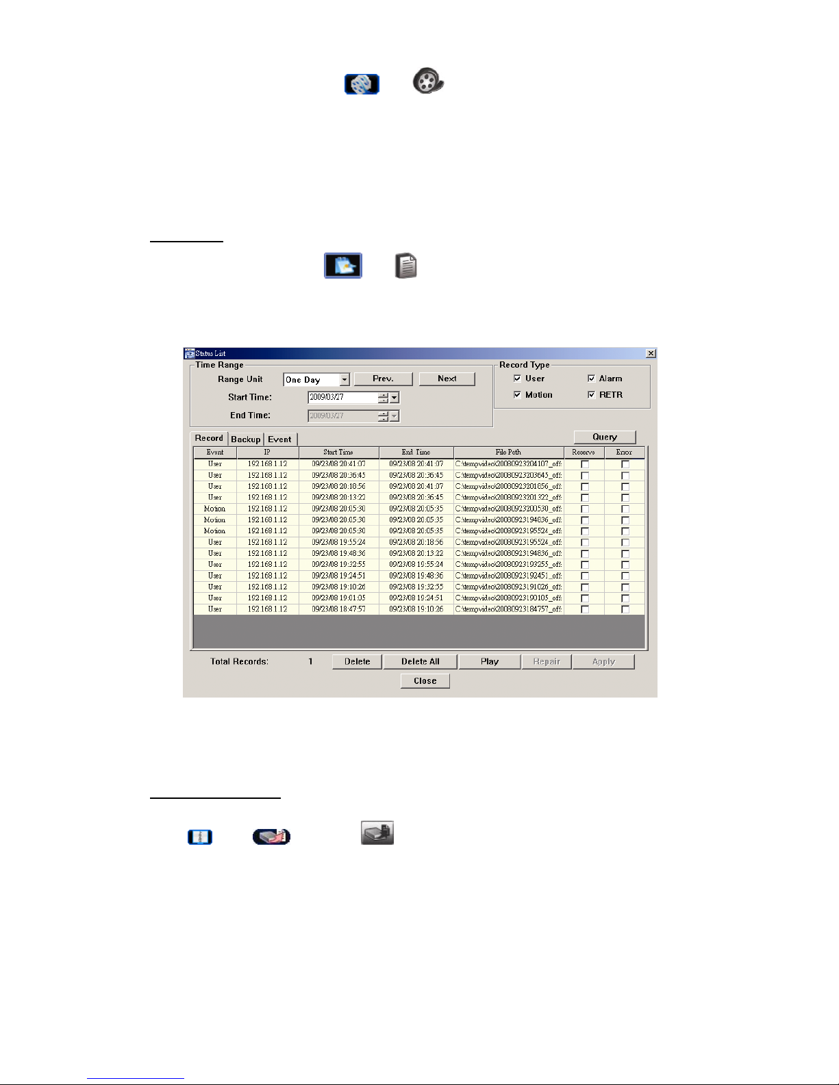
Playback
To play a recording, click “ ” or “ ”, and select the “Record” tab or “Backup” tab. A
list of all the recordings will be shown by defaults, and you can also sort out the logs you
want to speed up the search time.
To immediately play a recording, select a log from the list, and click “Play”, or
double-click the selected log.
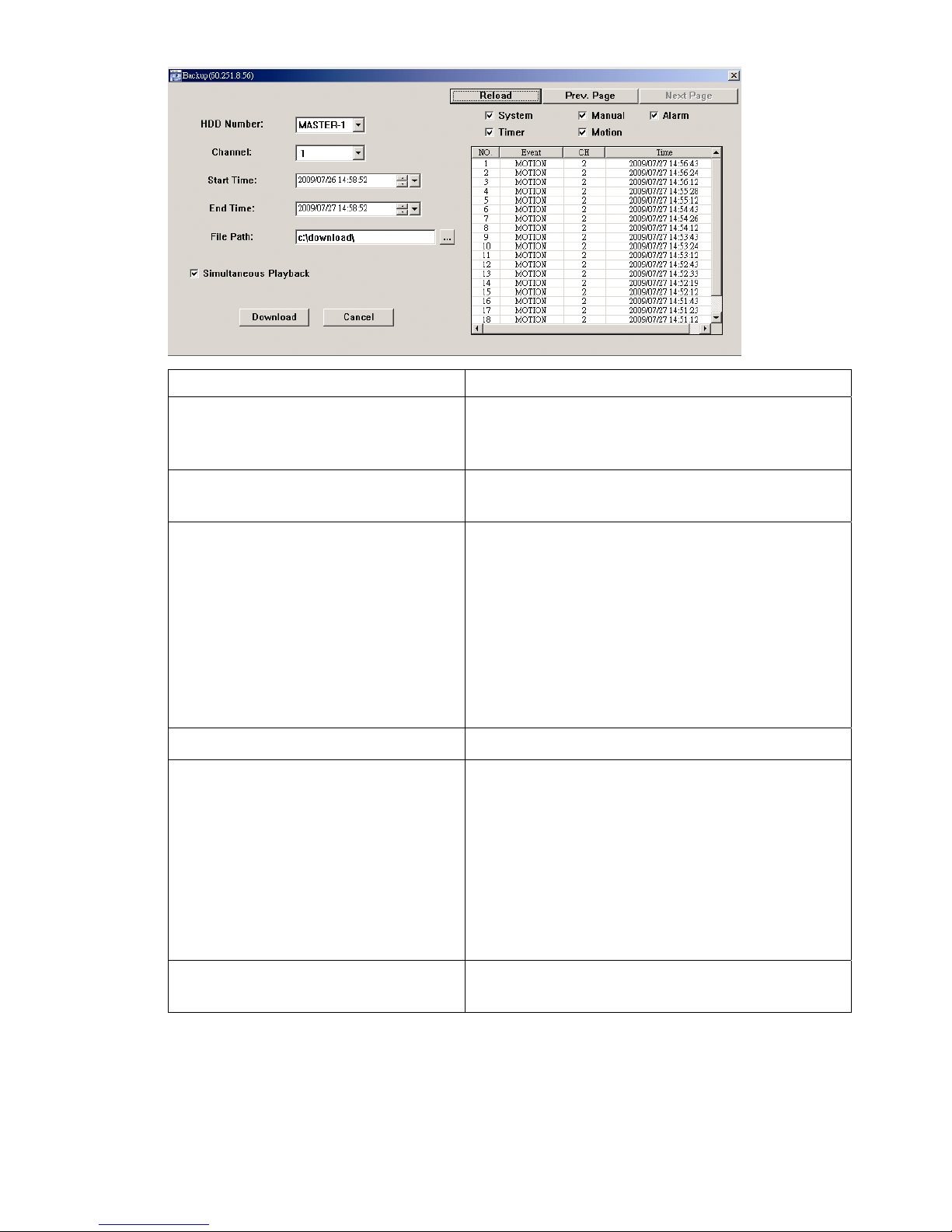
Network Backup
Click “ ” → “ ”, or click “ ” to go into the “Backup” page as follows, and you
can select a specific time range or event to make a video backup remotely.
The file(s) you backup will be from the currently selected IP address.
Page 44
REMOTE OPERATION
39
Function Description
HDD Number / Channel Specify the hard disk (HDD Number) and channel
number (Channel) within which have the video data you
need.
Download by Time Specify the time range within which has the video data
you want in the “Start Time” and “End Time” columns.
Download by Event Select an event log from the event list. This list shows
all logs in the specified DVR from the latest to the
earliest.
‧To quickly find the events you need, check or uncheck
the event type “System” / “Manual” / “Alarm” / “Motion”,
and select the log you want.
‧To view the earlier or later logs that are not shown in
the current page, click “Prev. Page” or “Next Page”.
‧To refresh the event list, click “Reload”.
File Path Assign the location where the backup files are saved.
Simultaneous Playback To view the backup images simultaneously when the
download process is in progress, select the checkbox
“Simultaneous Playback”. You will see the backup
images while the images are being downloaded to the
PC or notebook.
To simply backup images without previewing, deselect
the checkbox “Simultaneous Playback”. You will only
see a message box indicating the total time needed, the
current status and the saving location.
Download / Cancel Click “Download” to start or “Cancel” to discard the
video backup.
Page 45
REMOTE OPERATION
40
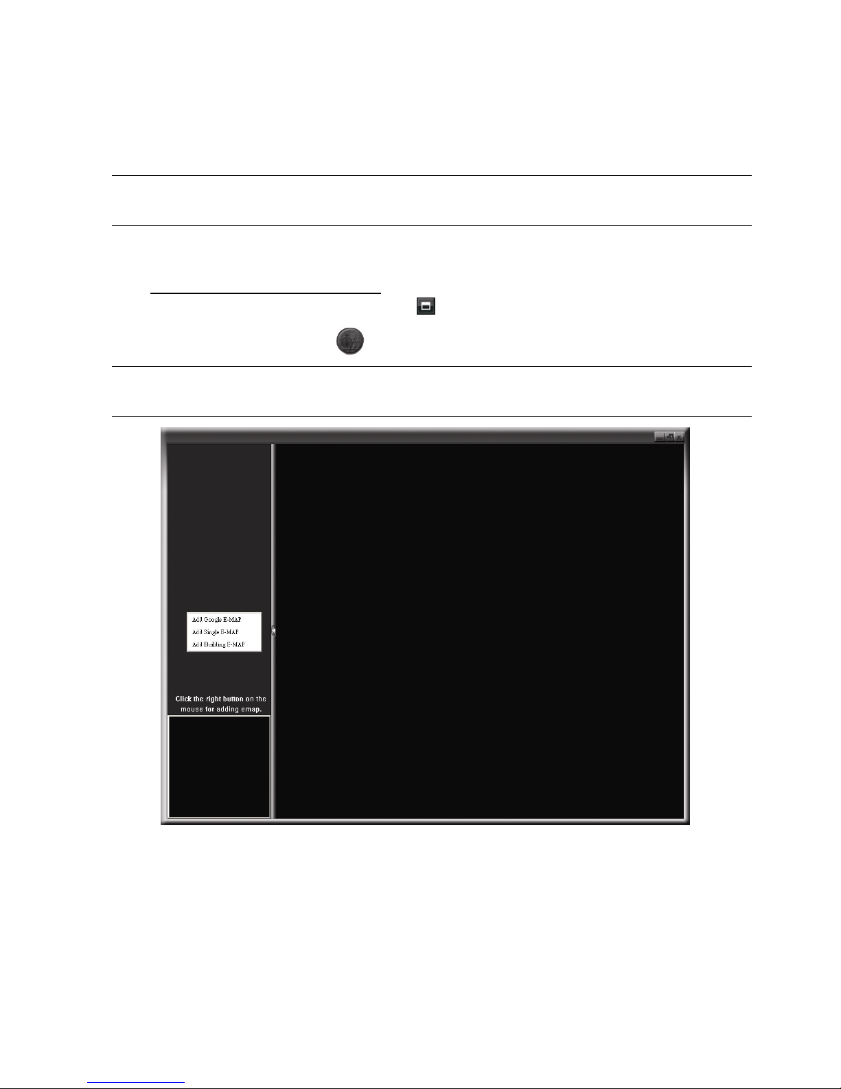
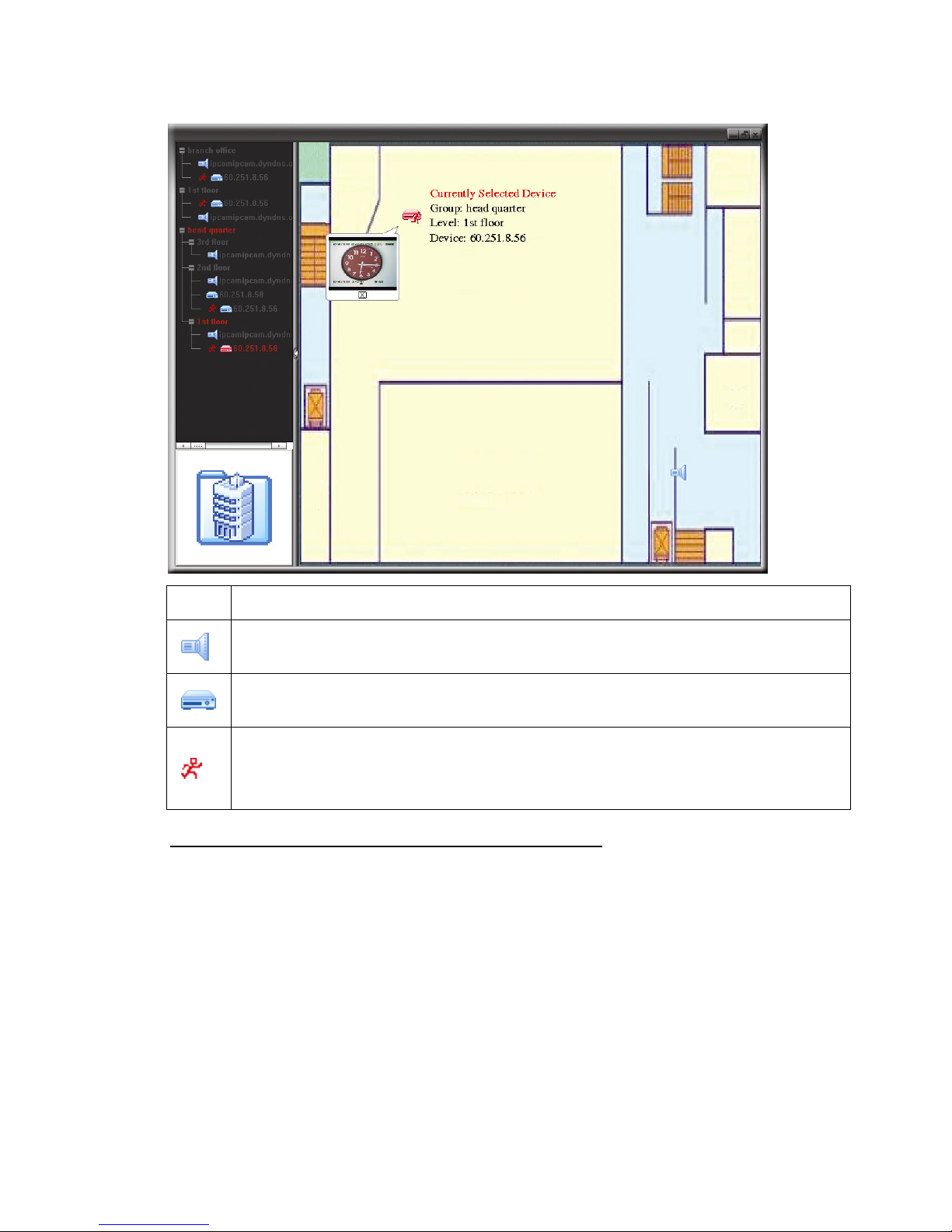
6.1.4. E-Map
Video Viewer is also a Central Management System (CMS) software, which allows
network device control & management for up to 16 devices simultaneously.
Note: Before using this function, make sure Video Viewer is connected to all the
devices (up to 16) you want to monitor.
E-Map is ONLY available when the control panel is switch to the full function version.
How to Add an E-Map Group
STEP1: In the simplified version, click “ ” to switch the control panel to the full function
version, and click “ ” to enter the E-Map page as follows.
Note: To know where the buttons are, please refer to “Simplified Version (Default)
at page 35, and “Full Function Version” at page 36.
STEP2: Right-click to show the shortcut menu on the top-left panel, and select the
E-Map group you want to add. There are three E-Map groups you can add:
Google E-MAP, Single E-MAP, and Building E-MAP.
Page 46
REMOTE OPERATION
41
Page 47
REMOTE OPERATION
42
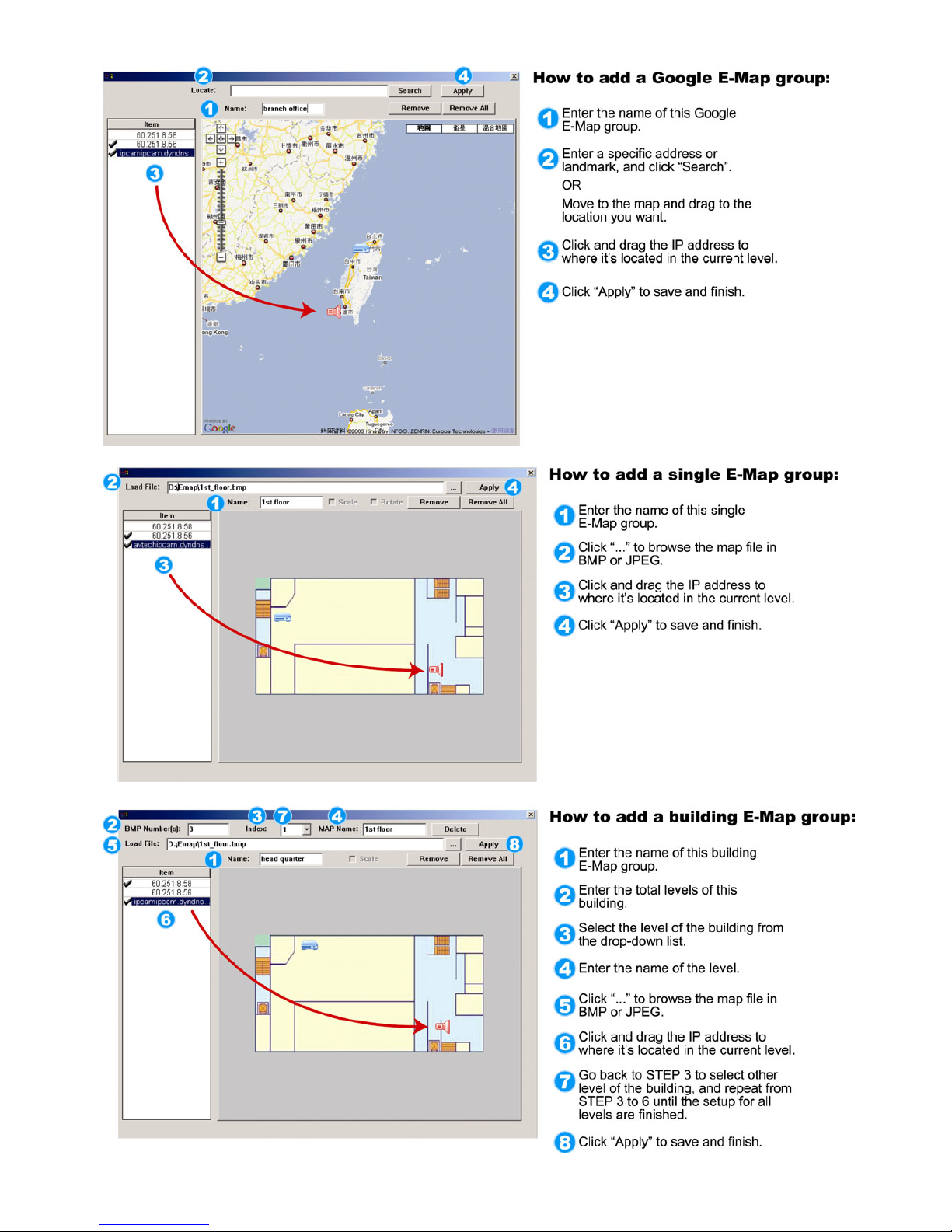
STEP3: When the E-Map group is created, you will see the tree on the top-left panel,
showing all the devices you’ve added to this group.
Icon Description
The connected device is camera. When it’s selected, it will become red.
The connected device is DVR. When it’s selected, it will become red.
For any motion or alarm event, it will appear on the screen to catch your
attention.
To know what’s happening quickly, double-click the device icon on the
E-Map to show the live view.
How to Edit / Remove an Existing E-Map Group
For Google E-Map Group
Right-click on the group name to show the shortcut menu list, and select “Edit
E-MAP” or “Remove E-MAP” as needed.
You can also add a single E-Map group (Add Single E-MAP) or Building
E-Map group (Add Building E-MAP) into the existing Google E-Map group.
Page 48

REMOTE OPERATION
43
For Single E-Map Group
Right-click on the group name to show the shortcut menu list, and select “Edit
E-MAP” or “Remove E-MAP” as needed.
Page 49
REMOTE OPERATION
44
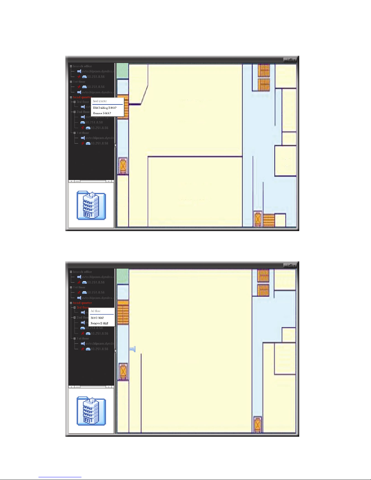
For Building E-Map Group
Right-click on the group name to show the shortcut menu list, and select “Edit
Building E-MAP” or “Remove E-MAP” as needed.
To edit or remove a certain level of the building E-Map group, right click on the
level name, and select “Edit E-MAP” or “Remove E-MAP” as needed.
Page 50
REMOTE OPERATION
45
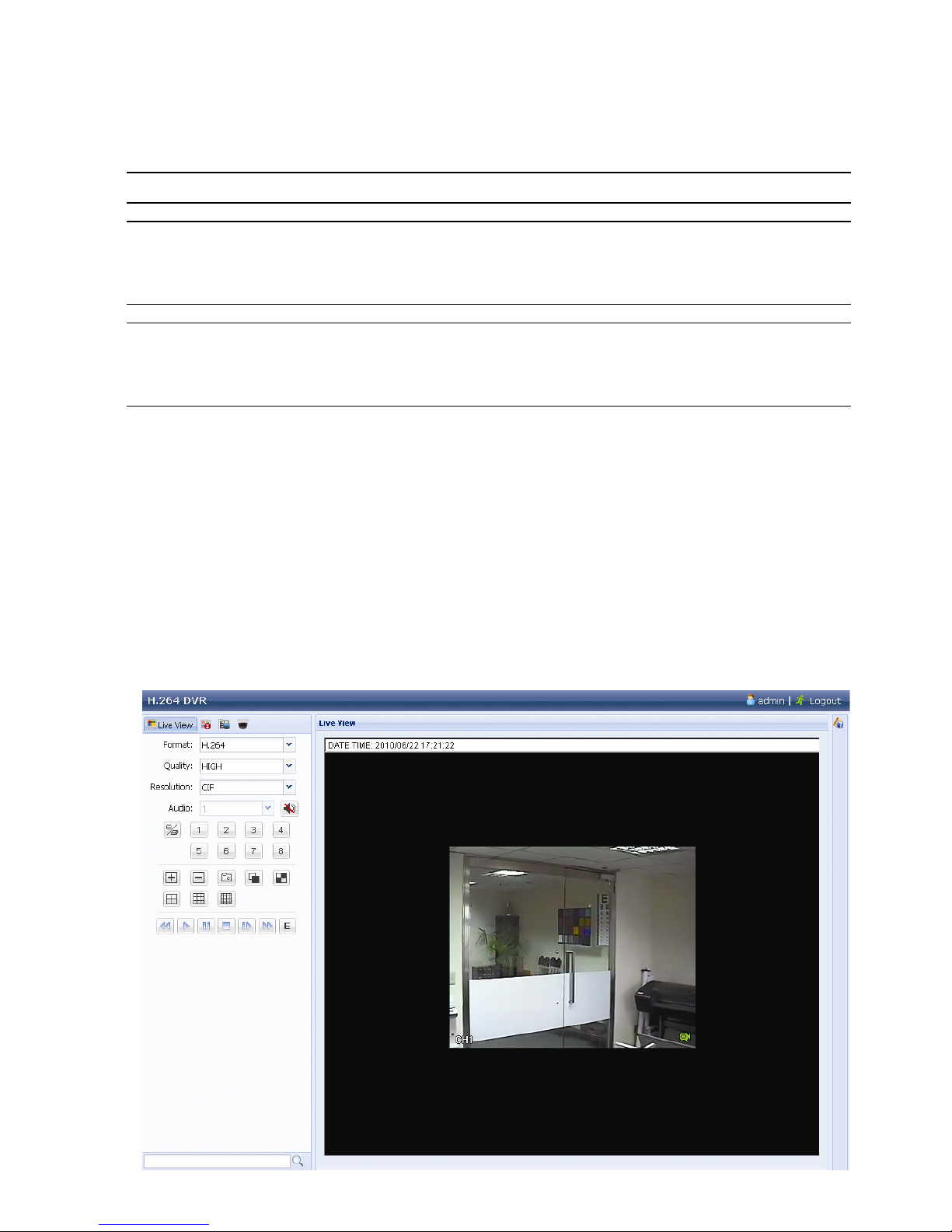
6.2 Web Browser
You can view the images or operate your DVR with a web browser, such as Internet
Explorer, Mozilla FireFox or Google Chrome.
Note: The supported PC operation systems are Windows 7, Vista, XP and 2000.
Note: To use Mozilla FireFox or Google Chrome for remote access, please go to
Apple’s official website (http://www.apple.com/quicktime/win.html) to
download and install QuickTime first.
Note: The illustration below is just for your reference and may be different from
what you actually see on your DVR. Some functions and buttons are for
selected models only.
Step 1: Key in the IP address used by your DVR in the URL address box, such as
60.121.46.236, and press Enter. You will be prompted to enter the user name and
password to access the DVR.
If the port number your DVR used is NOT 80, you need to key in the port number
additionally. The format is ipaddress:portnum. For example, for IP address
60.121.46.236 and port No. 888, please key in ”http://60.121.46.236:888” into the
URL address box, and press “Enter”.
Step 2: Enter the user name and password, the same as the ones used for video viewer
login, and click “OK”. You will see a similar screen as the following when the login
information is correct.
Page 51
REMOTE OPERATION
46
Icon Description
Click to go to the live view of the DVR.
(For Selected Models Only)
Click to enter the playback panel where you can search or select the event
you want to play and download to your PC simultaneously. For details,
please refer to “6.2.1 Event Download & Playback” at page 47.
Click to go to the detailed DVR setting.
(For Selected Models Only)
Click to enter the PTZ mode.
Video / Audio Control
Format
H.264 / QuickTime
QuickTime is Apple Inc.’s multimedia software. You need to have QuickTime
installed in you operation system first. When “QuickTime” is selected, you will
be promoted to enter the user name and password to access the server of
the DVR.
Quality
BEST / HIGH / NORMAL / BASIC
Select the image quality.
Resolution
4CIF: 704*480 pixels / CIF: 352*240 pixels
Audio
(For Selected Models Only)
Select the audio channel you want for listening to the live audio.
Note: Your camera must support audio recording, and connect to
the video channel which supports audio recording and the
audio input of the DVR. For details, please refer to “1.3 Rear
Panel” at page 3.
means mute.
To disable the mute status, click this icon again and select the audio channel
you want.
Channel Control
(For Selected Models Only)
Click to enable the remote independent operation. This icon will turn to blue,
and only the available function icons will be shown.
Channel Selection
Click one of the channel numbers to switch to the channel you want to see in
full screen.
/
Click to go to the previous / next channel, or change setting.
Click to take a snapshot of the current view, and save it to the specified
path in your PC set in “
” “General”.
:
Click to display four channels at a time. When the last channel is
displayed, it will start from CH1 again.
/
:
Click to display each channel one by one, starting from CH1. When the
last channel is displayed, it will start from CH1 again.
To exit from this display mode, press any other channel display button.
/ /
Click to show 4-cut / 9-cut / 16-cut display.
Playback Control
(For Selected Models Only)
Click to start playing the latest recorded video clip.
Increase the speed for fast rewind. Click once to get 4X speed rewind and
click twice to get 8X speed, etc., and the maximum speed is 16X.
Increase the speed for fast forward. Click once to get 4X speed forward and
click twice to get 8X speed, etc., and the maximum speed is 16X.
Page 52

REMOTE OPERATION
47
Icon Description
Click to play the current video clip.
Click to pause the video playback.
Click to stop the video playback.
Click to play the video clip slowly, once to get 4X slower, twice get 8X slower.
Click to open the playback search panel.
6.2.1 Event Download & Playback
/
Close all /
Close
Click
to close the current playback video clip (in the red frame), or
to close all playback video clips.
/
Previous /
Next Hour
Click to jump to the next / previous time interval in an hour, for example, 11:00
~ 12:00 or 14:00 ~ 15:00, and start playing the earliest event video clip
recorded during this whole hour.
Fast
Forward
Increase the speed for fast rewind. Click once to get 4X speed rewind and click
twice to get 8X speed, etc., and the maximum speed is 16X.
Fast Rewind
Increase the speed for fast forward. Click once to get 4X speed forward and
click twice to get 8X speed, etc., and the maximum speed is 16X.
Play
Click to play the current video clip.
Pause
Click to pause the video playback.
Stop
Click to stop the video playback.
Step
In the pause mode, click to get one frame forward.
Page 53

REMOTE OPERATION
48
Audio Click to mute the playback if necessary, and click again to restore.
Note: Audio is available when your camera supports audio recording,
and connects to the video channel which supports audio
recording and the audio input of the DVR. For details, please
refer to “1.3 Rear Panel” at page 3.
Snapshot
Click to take a snapshot of the current view, and save it to the specified path in
your PC set in “
” “General”.
Download
Click to download the current video clip to the specified path in your PC.
Page 54

APPENDIX 1 SPECIFICATIONS
49
APPENDIX 1 SPECIFICATIONS
For 16CH Models
Model 1 Model 2 Model 3
Video System NTSC / PAL (auto detection)
Video Compression Format H.264
Video Input
(composite video signal 1 Vp-p 75Ω BNC)
16 channels
Video Loop Output
(composite video signal 1 Vp-p 75Ω BNC)
-- 16 channels
Video Output (BNC) Main Monitor For stable display
Call Monitor -- For sequence display
Video Output (VGA) Built-in VGA interface for LCD monitor
Audio Input / Output 4 audio inputs / 1 audio output (Mono)
4 audio inputs / 2
audio outputs (Mono)
Maximum Recording Rate Frame
704×480 pixels with 120 IPS <NTSC> / 704×576 pixels with 100 IPS <PAL>
Field
--
704x240 pixels with 240
IPS <NTSC> /
704×288 pixels with 200
IPS <PAL>
CIF
352×240 pixels with 480 IPS <NTSC> / 352×288 pixels with 400 IPS <PAL>
Image Quality Setting SUPER BEST / BEST / HIGH /NORMAL
Hard Disk Storage** Accommodates 2 SATA HDDs
Quick Search Time / Motion / Alarm search mode
SATA Interface Built-in
VGA Interface Built-in
Recording Mode Manual / Timer / Motion / Alarm / Remote
Multiplex Operation Live display / record / playback / backup / network operations
USB Mouse Control YES
Motion Detection Area 16 × 12 grids per camera for all channels
Motion Detection Sensitivity 3 adjustable parameters for accurate detection
Pre-alarm Recording YES
Backup Device USB 2.0 flash drive / Network
DVD Writer
(Optional) / Flash
drive / Network
Web Transmitting Compression Format H.264
Ethernet 10/100 Base-T. Supports remote control and live view via Ethernet
Supports licensed software “Video Viewer” / Internet Explorer,
Mozilla Firefox & Google Chrome web browsers / QuickTime player
Web Interface
*Operating System: Windows 7 / Vista / XP / 2000
Max. Online User 5 10
Network Protocol TCP/IP, PPPOE, DHCP and DDNS
Remote Independent Operation YES
Remote Live Audio NO YES
Remote event download and playback YES
Event Notification By FTP / E-Mail
Page 55

APPENDIX 1 SPECIFICATIONS
50
Model 1 Model 2 Model 3
IR Remote Control YES (IR receiver built-in)
Mobile Surveillance YES (including iPhone, BlackBerry, Windows Mobile & Symbian)
Picture Zoom 2X digital zoom
PTZ Control YES
Alarm I/O 16 inputs, 1 output
Key Lock (Password Protection) YES
Local User Level Administrator & Operator
Video Loss Detection YES
Camera Title Supports up to 12 letters
Video Adjustable Hue / Saturation / Contrast / Brightness
Date Display Format YY/MM/DD, DD/MM/YY & MM/DD/YY
Daylight Saving YES
Power Source (±10%) DC 19V
Power Consumption (±10%) < 64 W
Operating Temperature 10 ~ 40 (50 ~104 )℃℃℉℉
Dimensions (mm)***
430(W) x 65(H) x
338(D)
432(W) × 90(H) × 326(D)
System Recovery System auto recovery after power failure
Optional Peripherals Keyboard controller
* The specifications are subject to change without notice.
** 1 HDD capacity up to 2TB
*** Dimensional Tolerance: ±5mm
Page 56
APPENDIX 1 SPECIFICATIONS
51
For 8CH Models
Model 4 Model 5 Model 6 Model 7
Video System NTSC / PAL (auto detection)
Video Compression Format H.264
Video Input
(composite video signal 1 Vp-p 75Ω BNC)
8 channels
Video Loop Output
(composite video signal 1 Vp-p 75Ω BNC)
-- 8 channels
Video Output (BNC) Main Monitor For stable display
Call Monitor -- For sequence display
Video Output (VGA) Built-in VGA interface for LCD monitor
Audio Input / Output 4 audio inputs / 1 audio output (Mono)
4 audio inputs /
2 audio outputs
(Mono)
Maximum Recording Rate Frame
704×480 pixels with 120 IPS <NTSC> /
704×576 pixels with 100 IPS <PAL>
--
704×480 pixels
with 120 IPS
<NTSC> / 704×57
6
pixels with 100 IPS
<PAL>
Field
--
704x240 pixels with
240 IPS <NTSC> /
704×288 pixels with
200 IPS <PAL>
CIF
352×240 pixels with 480 IPS <NTSC> / 352×288 pixels with 400 IPS <PAL>
Image Quality Setting
SUPER BEST / BEST / HIGH
/NORMAL
BEST / HIGH
/NORMAL
SUPER BEST
/
BEST / HIGH
/NORMAL
Hard Disk Storage**
Accommodates 2 SATA HDDs
A
ccommodates
1 SATA HDD
A
ccommodate
s
2 SATA HDDs
Quick Search Time / Motion / Alarm search mode
SATA Interface Built-in
VGA Interface Built-in
Recording Mode Manual / Timer / Motion / Alarm / Remote
Multiplex Operation
Live display / record / playback /
backup / network operations
--
Live display /
record /
playback /
backup /
network
operations
USB Mouse Control YES
Motion Detection Area 16 × 12 grids per camera for all channels
Motion Detection Sensitivity 3 adjustable parameters for accurate detection
Pre-alarm Recording YES
Backup Device USB 2.0 flash drive / Network
DVD Writer
(Optional) /
Flash drive /
Network
Web Transmitting Compression Format H.264
Ethernet 10/100 Base-T. Supports remote control and live view via Ethernet
Supports licensed software “Video Viewer” / Internet Explorer,
Mozilla Firefox & Google Chrome web browsers / QuickTime player
Web Interface
*Operating System: Windows 7 / Vista / XP / 2000
Page 57

APPENDIX 1 SPECIFICATIONS
52
Model 4 Model 5 Model 6 Model 7
Max. Online User 5 10
Network Protocol TCP/IP, PPPOE, DHCP and DDNS
Remote Independent Operation YES
Remote Live Audio NO YES
Remote event download and playback YES
Event Notification By FTP / E-Mail
IR Remote Control YES (IR receiver built-in)
Mobile Surveillance YES (including iPhone, BlackBerry, Windows Mobile & Symbian)
Picture Zoom 2X digital zoom
PTZ Control YES
Alarm I/O 8 inputs, 1 output
4 inputs, 1
output
8 inputs, 1
output
Key Lock (Password Protection) YES
Local User Level Administrator & Operator
Video Loss Detection YES
Camera Title Supports up to 12 letters
Video Adjustable Hue / Saturation / Contrast / Brightness
Date Display Format YY/MM/DD, DD/MM/YY & MM/DD/YY
Daylight Saving YES
Power Source (±10%) DC 19V
Power Consumption (±10%) < 64 W < 42 W < 64 W
Operating Temperature 10 ~ 40 (50 ~104 )℃℃℉℉
Dimensions (mm)***
430(W) x 65(H)
x 338(D)
432(W) × 90(H) ×
326(D)
343(W) × 59(H)
× 223(D)
432(W) × 90(H) ×
326(D)
System Recovery System auto recovery after power failure
Optional Peripherals Keyboard controller
* The specifications are subject to change without notice.
** 1 HDD capacity up to 2TB
*** Dimensional Tolerance: ±5mm
Page 58

APPENDIX 1 SPECIFICATIONS
53
For 4CH Model
Model 8 Model 9
Video System NTSC / PAL (auto detection)
Video Compression Format H.264
Video Input
(composite video signal 1 Vp-p 75Ω BNC)
4 channels
Video Output (BNC) Main Monitor: For stable display
Audio Input 4 audio inputs 1 audio input
(Mono) Output 1 audio output
Maximum Recording Rate Frame 704×480 pixels with 30 IPS <NTSC> / 704×576 with 25 IPS <PAL>
Field 704×240 pixels with 60 IPS <NTSC> / 704×288 pixels with 50 IPS <PAL>
CIF 352×240 pixels with 120 IPS <NTSC> / 352×288 pixels with100 IPS <PAL>
Image Quality Setting SUPER BEST / BEST / HIGH /NORMAL
Hard Disk Storage** Accommodates 1 SATA HDD
Quick Search Time / Motion / Alarm search mode
SATA Interface Built-in
VGA Interface Built-in
Recording Mode Manual / Timer / Motion / Alarm / Remote
Multiplex Operation Live display / record / playback / backup / network operations
USB Mouse Control YES
Motion Detection Area 16 × 12 grids per camera for all channels
Motion Detection Sensitivity 3 adjustable parameters for accurate detection
Pre-alarm Recording YES NO
Backup Device USB 2.0 flash drive / Network
Web Transmitting Compression Format H.264
Ethernet 10/100 Base-T. Supports remote control and live view via Etherne
t
Supports licensed software “Video Viewer” / Internet Explorer,
Mozilla Firefox & Google Chrome web browsers / QuickTime player
(5 users access simultaneously)
Web Interface
*Operating System: Windows 7 / Vista / XP / 2000
Network Protocol TCP/IP, PPPOE, DHCP and DDNS
Remote Independent Operation YES
Remote Live Audio YES NO
Remote Event Download & Playback YES
Event Notification By FTP / E-Mail
IR Remote Control YES (IR receiver built-in)
Mobile Surveillance YES (including iPhone, BlackBerry, Windows Mobile & Symbian)
Picture Zoom 2X digital zoom
PTZ Control YES NO
Alarm I/O 4 inputs, 1 output 4 inputs, 0 output
Key Lock (Password Protection) YES
Page 59

APPENDIX 1 SPECIFICATIONS
54
Model 8 Model 9
Local User Level Administrator & Operator
Video Loss Detection YES
Camera Title Supports up to 12 letters
Video Adjustable Hue / Saturation / Contrast / Brightness
Date Display Format YY/MM/DD, DD/MM/YY & MM/DD/YY
Daylight Saving YES
Power Source (±10%) DC 19V
Power Consumption (±10%) < 42 W
Operating Temperature 10 ~ 40 (50 ~104 )℃℃℉℉
Dimensions (mm)*** 343(W) × 59(H) × 223(D)
System Recovery System auto recovery after power failure
Optional Peripherals Keyboard controller NO
* The specifications are subject to change without notice.
** 1 HDD capacity up to 2TB
*** Dimensional Tolerance: ±5mm
Page 60

APPENDIX 2 COMPATIBLE USB FLASH DRIVE LIST
55
APPENDIX 2 COMPATIBLE USB FLASH DRIVE LIST
Please upgrade the firmware of the DVR to the latest version to ensure the accuracy of the
following table. If the USB flash drive is not supported by the DVR, the “USB ERROR”
message will be shown on the screen.
Note: Please use your PC to format the USB flash drive as “FAT32”.
Note: You can backup up to 2GB video data for one-time USB backup. To backup
more data, please set the time & channel(s) you want, and start USB
backup again.
MANUFACTURER MODEL CAPACITY
Transcend JFV35 4G
JFV30 8G
Kingston DataTraveler 1G
PQI U172P 4G
Apacer AH320 2GB
AH320A 8GB
AH220 1GB
AH320 4GB
A-data RB-18 1GB
Sandisk Cruzer Micro 2G
Cruzer Micro 4G
Cruzer4-pk 2G
Netac U208 1G
MSI F200 4G
SONY Micro Vault Tiny 2G 2G
Micro Vault Tiny 4G 4G
Micro Vault Tiny 1G
Page 61

APPENDIX 3 COMPATIBLE SATA HDD LIST
56
APPENDIX 3 COMPATIBLE SATA HDD LIST
Please upgrade the firmware of the DVR to the latest version to ensure the accuracy of the
following table.
MANUFACTURER MODEL CAPACITY ROTATION
ST3320613AS 320GB 7200 rpm
ST33500320AS 500GB 7200 rpm
ST3750330AS 750GB 7200 rpm
Seagate
ST31000340AS 1000GB 7200 rpm
WD3200AAKS 320GB 7200 rpm
WD5000AACS 500GB 7200 rpm
WD6400AAKS 640GB 7200 rpm
WD7500AAKS 750GB 7200 rpm
WD10EADS 1TB 7200 rpm
WD15EADS 1.5TB 7200 rpm
WD
WD20EADS 2TB 7200 rpm
STM3500320AS 500GB 7200 rpm Maxtor
STM3750330AS 750GB 7200 rpm
HDT725032VLA360 320GB 7200 rpm HITACHI
HDS721010KLA330 1000GB 7200 rpm
Page 62
APPENDIX 4 MAIN MENU STRUCTURE
57
APPENDIX 4 MAIN MENU STRUCTURE
QUICK START GENERAL CHANNEL TITLE
EVENT STATUS
DATE DISPLAY
IMAGE SIZE (For Selected Models Only)
QUALITY (For Selected Models Only)
I.P.S. (For Selected Models Only)
RECORD CONFIGURATION (For Selected Models Only)
TIME SETUP DATE
TIME
DATE SETUP DATE INFO DISPLAY DATE OF MODE
FORMAT
DAYLIGHT DAYLIGHT SAVING
SYSTEM TOOLS LANGUAGE
ADMIN PASSWORD
OPERATOR PASSWORD
UPGRADE
BACKUP CONFIG (For Selected Models Only)
RESTORE CONFIG (For Selected Models Only)
SYSTEM INFO BAUD RATE
HOST ID
R.E.T.R. (For Selected Models Only)
AUTO KEY LOCK
CLEAR HDD
RESET DEFAULT
REMOTE CONTROL ID
SERIAL TYPE
VIDEO FORMAT
VERSION
USB BACKUP
DVD BACKUP
(For Selected Models Only)
EVENT INFORMATION QUICK SEARCH
EVENT SEARCH
HDD INFO
EVENT LOG
ADVANCE CONFIG CAMERA BRIGHTNESS
CONTRAST
SATURATION
HUE
COV.
REC
CHANNEL TITLE
DETECTION LS
SS
TS
DET
ALARM
AREA
ALERT EXT. ALERT
INT. BUZZER
KEY BUZZER
VLOSS BUZZER
MOTION BUZZER
ALARM BUZZER
HDD BUZZER
ALARM DURATION (SEC)
HDD NEARLY FULL (GB)
NETWORK NETWORK
SNTP
FTP
E-MAIL
Page 63
APPENDIX 4 MAIN MENU STRUCTURE
58
ADVANCE CONFIG DISPLAY DE-INTERLACE (For Selected Models Only)
FULL SCREEN DURATION
QUAD SCREEN DURATION (For Selected Models Only)
DWELL SCREEN DURATION (For Selected Models Only)
DISPLAY COVERT
HDD DISPLAY MODE
DISPLAY OUTPUT PATH (For Selected Models Only)
ALPHA BLENDING (For Selected Models Only)
FULL SPEED PLAY (For Selected Models Only)
RECORD MANUAL RECORD ENABLE
EVENT RECORD ENABLE
TIMER RECORD ENABLE
EVENT RECORD IPS (For Selected Models Only)
TIMER RECORD IPS (For Selected Models Only)
PRE-ALARM RECORD (For Selected Models Only)
OVERWRITE
EVENT RECORD ALL CHANNEL
KEEP DATA LIMIT (DAYS)
RECORD CONFIGURATION (For Selected Models Only)
REMOTE
(For Selected Models Only)
SCHEDULE SETTING RECORD
DETECTION
ALARM
Page 64

APPENDIX 5 DVR BATTERY REPLACEMENT
59
APPENDIX 5 DVR BATTERY REPLACEMENT
DVR time reset after power failure, for example, caused by a power outage, will cause the
disorder of the recorded data, and users may have problems in searching the event clip they
want. To keep the DVR time from resetting, a non-chargeable lithium battery, CR2032, is
installed in the DVR.
However, the DVR time might still get reset when the DVR battery is low or even running out of
power. If so, please replace the DVR battery, CR2032, right away as instructed below.
How to replace CR2032
Note: The lithium battery, CR2032, is a non-chargeable battery, and should be
purchased separately. Please replace only with the same or equivalent type
battery in case of danger.
Step1: Stop all DVR recording immediately to prevent the disorder of the recorded data.
Then, back up the recorded data if necessary.
Step2: Power off the DVR, and disconnect the DVR power.
Step3: Remove the DVR cover, and find the battery on the mainboard.
Step4: Push the release as indicated below to remove the battery.
Step5: Get a new battery with the side of “CR2032” facing up, and install it to the mainboard.
Step6: Replace the DVR cover and connect to power.
Step7: Set DVR date & time, and resume recording. For details, please refer to “2.4 Date and
Time Setting” at page 10, and “5.2 Record” at page 20.
Page 65

APPENDIX 6 PIN CONFIGURATION
60
APPENDIX 6 PIN CONFIGURATION
‧ For 16CH Model
Siren:
When the DVR is triggered by alarm or motion, the
COM connects with NO and the siren with strobe
starts wailing and flashing.
* The D-Sub connector shown above is optional.
Magnetic Contact:
When the magnetic contact is opened, the alarm
will be triggered and the recording is on.
PIN FUNCTION DESCRIPTION
1 GND GROUND
2~9 ALARM INPUT
Connect ALARM INPUT (PIN 2 -- 9) and GND (PIN 1) connector with wires. Once
an alarm is triggered, the DVR will start recording and the buzzer will be on.
PIN Alarm Corresponding video channel
PIN 2 1 CH1
PIN 3 3 CH3
PIN 4 5 CH5
PIN 5 7 CH7
PIN 6 9 CH9
PIN 7 11 CH11
PIN 8 13 CH13
PIN 9 15 CH15
*
10~11 PIN OFF NA
12 RS485-A
13 EXTERNAL ALARM NO
Under the normal operation, COM disconnects with NO. But when any alarm is
triggered, COM connects with NO.
Attention: The voltage restriction is under DC24V 1A.
14 PIN OFF NA
15~22 ALARM INPUT
Connect ALARM INPUT (PIN 15 – 22) and GND (PIN 1) connector with wires.
Once an alarm is triggered, the DVR will start recording and the buzzer will be on.
PIN Alarm Corresponding video channel
PIN 15 2 CH2
PIN 16 4 CH4
PIN 17 6 CH6
PIN 18 8 CH8
PIN 19 10 CH10
PIN 20 12 CH12
PIN 21 14 CH14
PIN 22 16 CH16
*
23~23 PIN OFF NA
24 RS485-B
25
EXTERNAL ALARM
COM
Under the normal operation, COM disconnects with NO. But when any alarm is
triggered, COM connects with NO.
Attention: The voltage restriction is under DC24V 1A.
Page 66
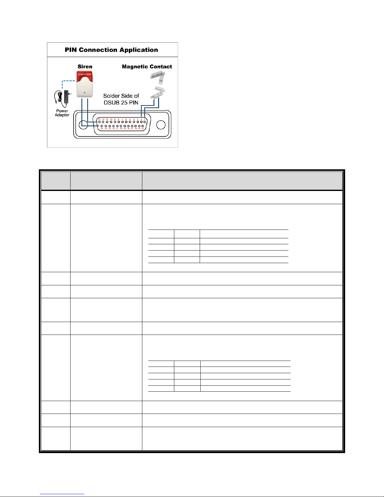
APPENDIX 6 PIN CONFIGURATION
61
‧ For Selected 8CH Model
Siren:
When the DVR is triggered by alarm or motion, the
COM connects with NO and the siren with strobe
starts wailing and flashing.
* The D-Sub connector shown above is optional.
Magnetic Contact:
When the magnetic contact is opened, the alarm
will be triggered and the recording is on.
PIN FUNCTION DESCRIPTION
1
GND GROUND
2~5
ALARM INPUT
Connect ALARM INPUT (PIN 2 – 5) and GND (PIN 1) connector with
wires. Once an alarm is triggered, the DVR will start recording and the
buzzer will be on.
PIN Alarm Corresponding video channel
PIN 2 1 CH1
PIN 3 3 CH3
PIN 4 5 CH5
PIN 5 7 CH7
*
6 ~ 11
PIN OFF NA
12
RS485-A
13
EXTERNAL ALARM NO.
Under the normal operation, COM disconnects with NO. But when any
alarm is triggered, COM connects with NO.
Attention: The voltage restriction is under DC24V 1A.
14
PIN OFF NA
15~18
ALARM INPUT
Connect ALARM INPUT (PIN 15 – 18) and GND (PIN 1) connector with
wires. Once an alarm is triggered, the DVR will start recording and the
buzzer will be on.
PIN Alarm Corresponding video channel
PIN 15 2 CH2
PIN 16 4 CH4
PIN 17 6 CH6
PIN 18 8 CH8
*
19~23
PIN OFF NA
24
RS485-B
25
EXTERNAL ALARM
COM
Under the normal operation, COM disconnects with NO. But when any
alarm is triggered, COM connects with NO.
Attention: The voltage restriction is under DC24V 1A.
Page 67
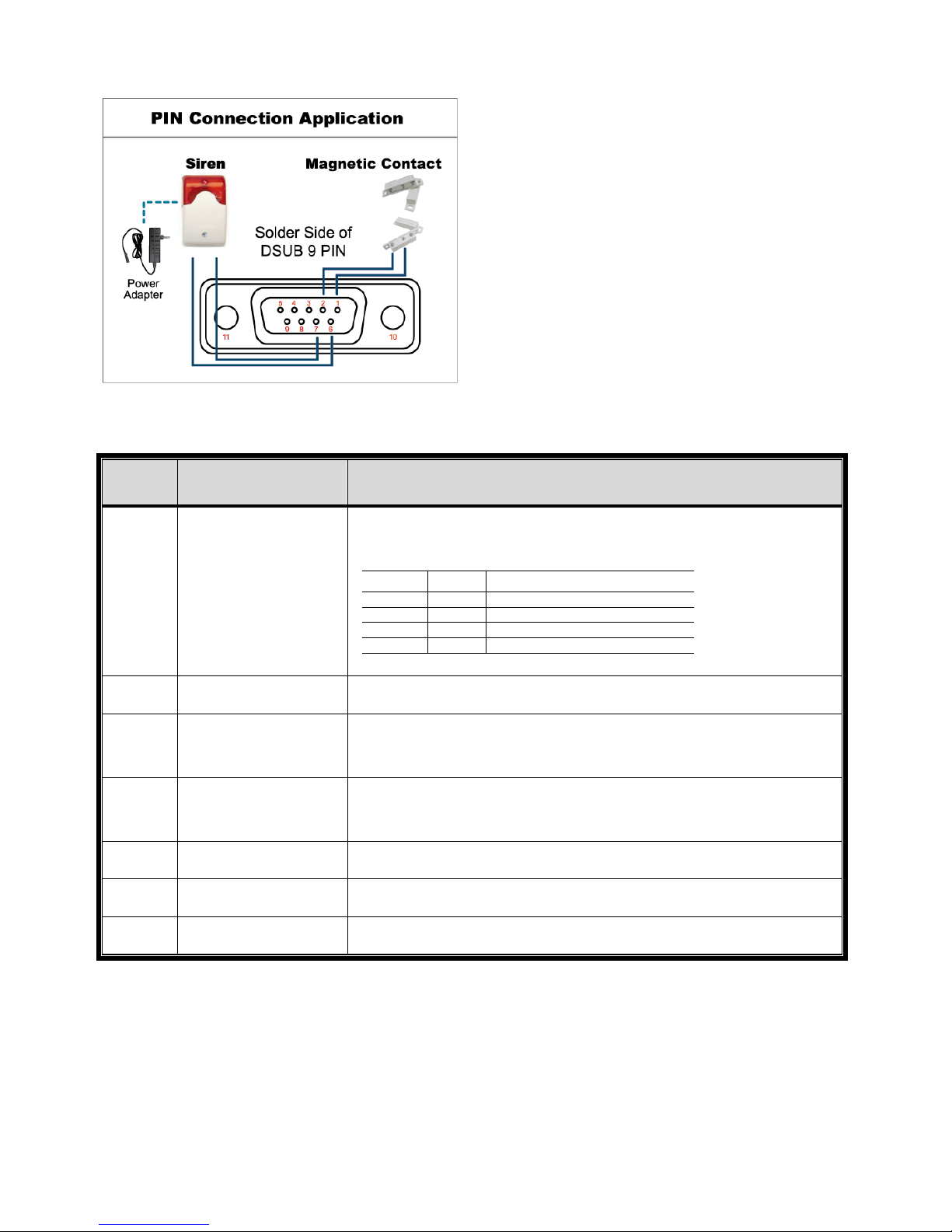
APPENDIX 6 PIN CONFIGURATION
62
‧ For 4CH Model & Selected 8 CH Model
Siren:
When the DVR is triggered by alarm or motion,
the COM connects with NO and the siren with
strobe starts wailing and flashing.
* The D-Sub connector shown above is optional.
Magnetic Contact:
When the magnetic contact is opened, the alarm
will be triggered and the recording is on.
PIN FUNCTION DESCRIPTION
1~4
ALARM INPUT
Connect ALARM INPUT (PIN1 – 4) and GND (PIN5) connector with wires.
Once an alarm is triggered, the DVR will start recording and the buzzer
will be on.
PIN Alarm Corresponding video channel
PIN 1 1 CH1
PIN 2 2 CH2
PIN 3 3 CH3
PIN 4 4 CH4
*
5
GND GROUND
6
EXTERNAL ALARM
COM
Under the normal operation, COM disconnects with NO. But when any
alarm is triggered, COM connects with NO.
Attention: The voltage restriction is under DC24V 1A.
7
EXTERNAL ALARM
NO
Under the normal operation, COM disconnects with NO. But when any
alarm is triggered, COM connects with NO.
Attention: The voltage restriction is under DC24V 1A.
8
RS485-A
For Selected Models Only
9
RS485-B
For Selected Models Only
10~11
GND
GROUND
Page 68
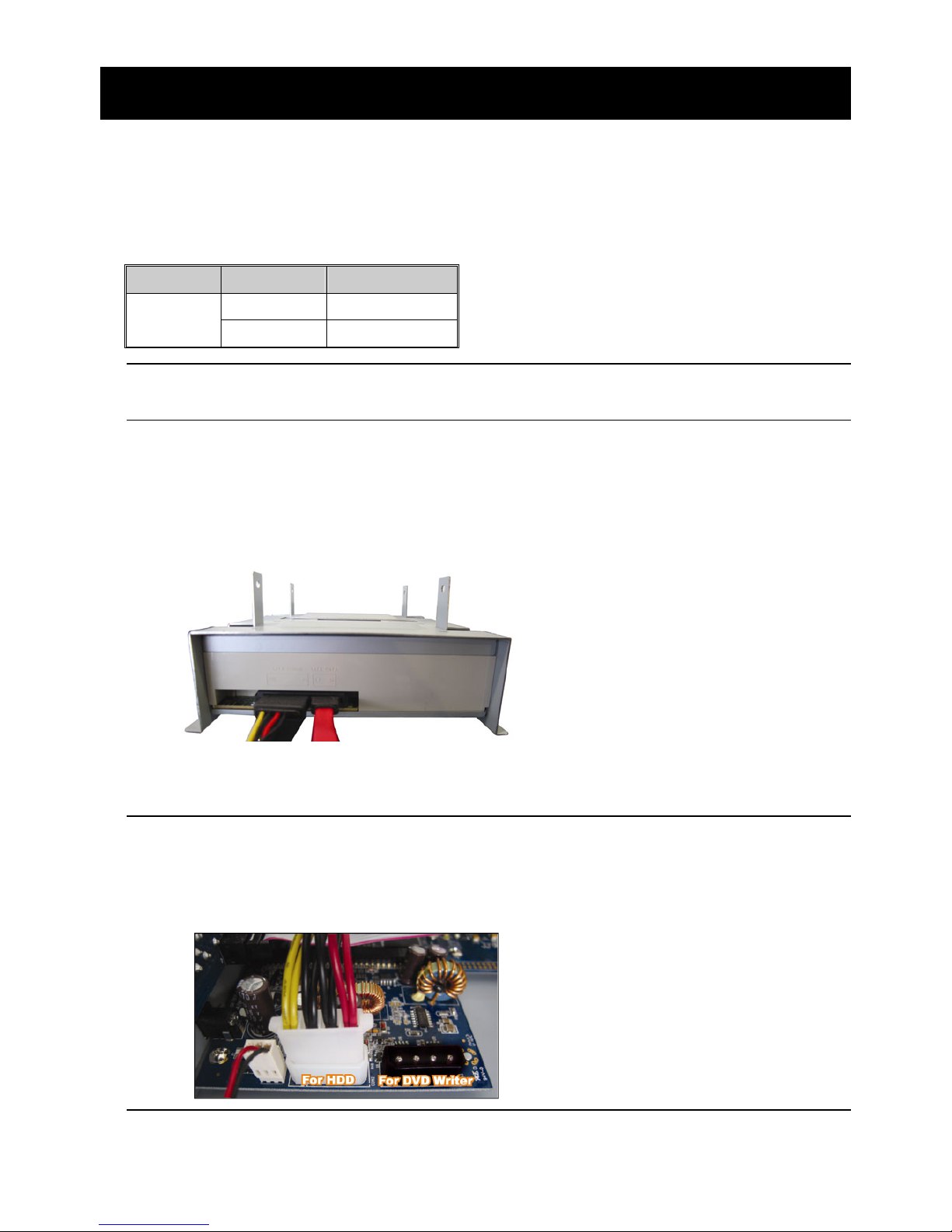
APPENDIX 7 DVD WRITER INSTALLATION
63
APPENDIX 7 DVD WRITER INSTALLATION
Some DVR models allow users to install a DVD writer by themselves. To know whether your
DVR supports this feature, please check with your local distributor or retailer.
The supported DVD writer models are as follows. Please use only the suggested DVD writer
models to ensure the compatibility.
Type Brand Model
SATA Liteon iHAS120
SONY AD-7240S
Note: Before installing the DVD writer, make sure your DVR is powered off and
your DVR supports this feature.
Step1: Remove the DVR cover, and find the DVD writer bracket to remove it.
Step2: Put the DVD writer in the bracket, and fix it to the bracket with two screws (optional) on
each side.
Step3: Connect the data bus and power cables* to the SATA DVD writer.
*Data bus & power cables are optional.
Step4: Connect the data bus and power cables to the data bus and power jack on the DVR
main board.
Note: Make sure the power cable of the DVD writer is plugged into the black jack
on the DVR main board. This power jack can supply power to one hard disk
and one DVD writer simultaneously. The white jack is used to supply power
to only one hard disk.
Step5: Replace the bracket to the DVR base and fix it.
Page 69

APPENDIX 8 DVD- / CD-ROM COMPATIBLE LIST
64
APPENDIX 8 DVD- / CD-ROM COMPATIBLE LIST
‧ DVD-ROM List
Disc Type Manufacturer Disc MID-TID Code
20X DVD+R RITEK RITEK R05 (rev:och)
16X DVD+R SONY SONY....-D21
TAIYO YUDEN YUDEN000-T03
MITSUBISHI MCC.....-004
TDK TDK.....-003
MAXELL MAXELL..003
MBI MBIPG101-R05
CMC CMC MAG.-M01
DAXON DAXON...-AZ3
RITEK RITEK...-R05
PRODISC PRODISC.-R05
8X DVD+R TAIYO YUDEN YUDEN000-T02
MITSUBISHI MCC.....-003
CMC CMC MAG.-E01
PRODISC PRODISC.-R03
8x DVD+RW Ritek RITEK...-008
MITSUBISHI MKM.....-A03
4X DVD+RW SONY SONY....-S11
MITSUBISHI MKM.....-A02
RITEK RITEK...-004
16X DVD+R9 RITEK RITEK S06
8X DVD+R9 MITSUBISHI MKM.....-003
CMC CMC MAG-D02
RITEK RITEK...-D03
2.4X DVD+R9 MITSUBISHI MKM.....-001
20X DVD-R RITEK RITEKF-2
16x DVD-R SONY SONY16-D1
TAIYO YUDEN TYG03
MITSUBISHI MCC 03 RG20
TDK TTH02
MAXELL MXL RG04
MBI MBI 01-RG40
CMC CMC MAG.AM3
RITEK RITEK F1
8X DVD-R RITEK RITEKG 05
SONY SONY08 D1
PRODISC PRODISCS04
TAIYO YUDEN TYG02
MITSUBISHI MCC 02RG20
TDK TTH01
MAXELL MXL RG03
CMC CMC MAG.AE1
Page 70
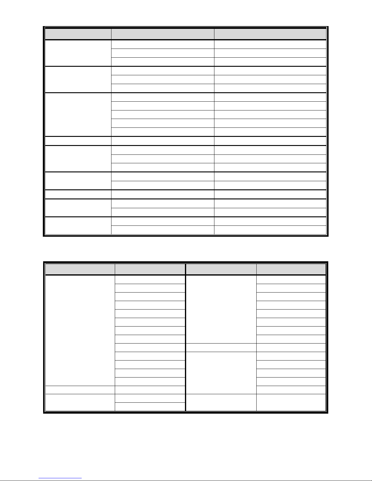
APPENDIX 8 DVD- / CD-ROM COMPATIBLE LIST
65
Disc Type Manufacturer Disc MID-TID Code
6X DVD-RW MITSUBISHI MCC 01RW6X01
JVC JVC1Victord7
RITEK RITEK W06
4X DVD-RW MITSUBISHI MCC 01RW4X
TDK TDK601saku
RITEK RITEKW04
2X DVD-RW MITSUBISHI MCC 01RW11N9
JVC JVC_VictorW7
TDK TDK502 sakuM3
CMC CMCW02
RITEK RITEK W01
12X DVD-R9 MKM MKM 04 RD30
8X DVD-R9 TY TYG11
MITSUBISHI MKM 03 RD30
RITEK RITEKP 02
4X DVD-R9 MITSUBISHI MKM 01 RD30
RITEK RITEKP 01
12X DVD-RAM MAXELL MXL22.
5X DVD-RAM Matsushita Matsushita-M01J5006
MAXELL MXL16.
3X DVD-RAM MAXELL MXL9.
Matsushita Matsushita-M01J3003
‧ CD-ROM List
Disc Type Manufacturer Disc Type Manufacturer
52X CD-R MCC 12X CD-RW MCC
MBI MBI
TAIYO YUDEN DAXON
RITEK RITEK
UME MCC
PRODISC DAXON
DAXON Lead Data
TDK PRINCO
CMC 10X CD-RW CMC
Princo 4X CD-RW MCC
Lead Data DAXON
Postec CMC
Giga RITEK
32X CD-R TAIYO YUDEN DAXON
24X CD-RW MCC 4X CD-RW (8 cm) INFODISC
INFODISC
Page 71

338Z
中文_K674_677_679_C551_A791A_798A_796A_M751_757_759_688A_686A_Manual_V1.2
H.264 數位錄放影機
使用說明書
支援圖形化介面與 USB 滑鼠控制
在使用本機前請務必詳細閱讀安全須知及操作說明,並保存此手冊以備後續參考。
產品畫面顯示與操作請以實機為主。
Page 72
安全須知
注意
RISK OF ELECTRIC SHOCK
注意:
為減低觸電的可能性,請勿讓此機器暴露在雨中或潮濕的環境下。請務必使用適當的變壓器。本公司不負
責賠償任何因不當使用本產品所引起的損害。即使本公司已被告知可能的相關風險,使用者仍應自行承擔
不當使用所產生之後果。
此符號用於警告使用者 產品機殼內部有 “危險電壓”,觸碰有可能會造成觸電的可能性。.
此符號用於告知使用者此機器附有操作與維護指示的重要文件。
本公提供的所有無鉛產品皆符合歐盟有害物質使用限制指引 (Restriction of Hazardous
Substances, (RoHS)),意即本公司的生產流程與產品均嚴格遵守無鉛守則,而且不包含該指引內
提供的任何有害物質。
此劃叉的滾輪垃圾筒圖示代表在歐盟境內,本產品於丟棄時必須另行收集。此原則適用於您的產
品與任何標有此圖示的週邊設備。請勿隨意丟棄這些產品。請洽詢您當地的經銷商,以得知回收此
設備的程序。
此機器的製造符合無線電波干擾的規範。
免責聲明
本說明書資訊在付梓時都是最新的。本公司保留可隨時修改或刪除說明書內容的任何權利。本公司不保證此說明書
的內容完全無誤、完整或實用性。產品畫面顯示與操作請以實機為主。此說明書內容更改以實際產品為準,將不另
行通知。
在此提及的產品與公司名稱,也許為其各自擁有者的註冊商標或商稱名稱。
接地
此為符合 Safety Class 1 Product (隨附的電源插頭有內建接地線) 的產品,其主電源插頭應插入支援接地線的三孔
電源插座。任何破壞接地保護的舉動都可能會使得本產品具有危險性。因此,請勿刻意破壞接地保護。
遠離有水或潮溼的環境
請勿讓本產品曝露在任何有水或潮溼的環境下,例如將水瓶放在本產品上,或者容易滴到雨水的窗戶邊。
Page 73

Version
韌體版本: 1019-1008-1010-1010
MPEG4
授權
THIS PRODUCT IS LICENSED UNDER THE MPEG-4 VISUAL PATENT PORTFOLIO LICENSE FOR
THE PERSONAL AND NON-COMMERCIAL USE OF A CONSUMER FOR (i) ENCODING VIDEO IN
COMPLIANCE WITH THE MPEG-4 VISUAL STANDARD (“MPEG-4 VIDEO”) AND/OR (ii) DECODING MPEG-4
VIDEO THAT WAS ENCODED BY A CONSUMER ENGAGED IN A PERSONAL AND NON-COMMERCIAL
ACTIVITY AND/OR WAS OBTAINED FROM A VIDEO PROVIDER LICENSED BY MPEG LA TO PROVIDE
MPEG-4 VIDEO. NO LICENSE IS GRANTED OR SHALL BE IMPLIED FOR ANY OTHER USE. ADDITIONAL
INFORMATION INCLUDING THAT RELATING TO PROMOTIONAL INTERNAL AND COMMERCIAL USES
AND LICENSING MAY BE OBTAINED FROM MPEG LA, LLC. SEE HTTP://WWW.MPEGLA.COM.
GPL
授權
This product contains codes which are developed by Third-Party-Companies and which
are subject to the GNU General Public License (“GPL”) or the GNU Lesser Public License
(“LGPL”).
The GPL Code used in this product is released without warranty and is subject to the
copyright of the corresponding author.
Further source codes which are subject to the GPL-licenses are available upon request.
We are pleased to provide our modifications to the Linux Kernel, as well as a few new
commands, and some tools to get you into the code. The codes are provided on the FTP
site, and please download them from the following site or you can refer to your distributor:
ftp://ftp.dvrtw.com.tw/GPL/AV074/
Page 74

目錄
1. 開始使用之前................................................................................................................... 1
1.1 包裝明細...................................................................................................................... 1
1.2 前面板......................................................................................................................... 1
1.3 背板............................................................................................................................. 2
2. 連接與設定....................................................................................................................... 4
2.1 SATA 硬碟安裝............................................................................................................. 4
2.2 攝影機連接.................................................................................................................. 5
2.2.1 一般攝影機連接................................................................................................... 6
2.2.2 PTZ 攝影機連接................................................................................................... 6
2.3 DVR 開機..................................................................................................................... 7
2.4 日期與時間設定............................................................................................................ 8
2.5 清除硬碟資料............................................................................................................... 8
2.6 密碼設定...................................................................................................................... 9
3. 圖形化介面與 USB 滑鼠控制簡介................................................................................... 10
3.1 連接 USB 滑鼠........................................................................................................... 10
3.2 快速選單列................................................................................................................ 10
3.2.1 頻道切換 ........................................................................................................... 11
3.2.2 PTZ 控制面板..................................................................................................... 11
3.3 主目錄選單................................................................................................................ 12
4. 基本操作 ........................................................................................................................13
4.1 即時畫面..................................................................................................................... 13
4.2 錄影圖示.................................................................................................................... 13
4.3 影像回放.................................................................................................................... 14
4.3.1 回放操作 ........................................................................................................... 14
4.3.2 事件搜尋 ........................................................................................................... 14
4.3.3 錄音回放 ........................................................................................................... 15
4.4 切換使用權限............................................................................................................. 15
4.5 影像輸出切換............................................................................................................. 15
5. 常用功能 ........................................................................................................................17
5.1 快速搜尋.................................................................................................................... 17
5.2 錄影設定.................................................................................................................... 17
5.2.1 錄影快速設定.................................................................................................... 17
5.2.2 錄影詳細設定.................................................................................................... 18
5.3 預約設定.................................................................................................................... 19
5.3.1 預約錄影 ........................................................................................................... 19
5.3.2 預約偵測錄影.................................................................................................... 20
5.4 偵測設定.................................................................................................................... 20
Page 75

5.5 PTZ 攝影機設定 ......................................................................................................... 21
5.6 系統設定.................................................................................................................... 22
5.6.1 密碼設定 ........................................................................................................... 22
5.6.2 系統更新 ........................................................................................................... 22
5.6.3 影像備份 ........................................................................................................... 23
5.6.4 清除所有硬碟資料............................................................................................. 24
5.7 網路設定.................................................................................................................... 24
6. 遠端操作 ........................................................................................................................26
6.1 免費授權軟體............................................................................................................. 26
6.1.1 軟體安裝 & 網路連線....................................................................................... 26
6.1.2 控制面板簡介.................................................................................................... 28
6.1.3. 常用功能 .......................................................................................................... 30
6.1.4. E-Map............................................................................................................... 33
6.2 IE 網路瀏覽器............................................................................................................. 38
6.2.1 事件回放與下載................................................................................................. 39
附錄 1 產品規格................................................................................................................. 41
附錄 2 相容 USB 隨身碟品牌 ............................................................................................. 45
附錄 3 相容 SATA 硬碟表................................................................................................... 46
附錄 4 主目錄選單架構....................................................................................................... 47
附錄 5 更換 DVR 電池........................................................................................................ 49
附錄 6 PIN 腳解說............................................................................................................... 50
附錄 7 DVD 燒錄機安裝...................................................................................................... 53
Page 76

開始使用之前
1
1. 開始使用之前
1.1 包裝明細
16 路 / 8 路機種
數位錄放主機 硬碟螺絲
IR 紅外線遙控器 IR 紅外線遙控器說明書
IR 紅外線接收延長線 CD 說明書
變壓器和電源線 USB 滑鼠
25 PIN DSUB 接頭
4 路機種
數位錄放主機 硬碟螺絲
IR 紅外線遙控器 (
僅限特定型號
) IR 紅外線遙控器說明書
CD 說明書 變壓器和電源線
1.2 前面板
1) LED 顯示燈
硬碟正在讀取資料或錄影中。
已觸發警報。
已啟動預約錄影。
DVR 處於回放模式下。
DVR 已開機。
2) (▲) / (▼) / (◄) / (►)
按 ▲ / ▼ / ◄ / ► 上 / 下 / 左 / 右移動。
在回放模式下:
按暫停回放。
按停止回放。
按快轉。
按倒轉。
3) MENU (目錄選單)
按 MENU 進入主目錄選單。
4) ENTER (輸入)
按 ENTER 確認設定。
5) LIST (事件搜尋)
按 LIST 可依事件快速搜尋錄影資料:錄影清單 / 位移事件清單 / 警報事件清單 / 時間
清單,或者選擇全部事件清單顯示所有事件記錄。
若要進行時間搜尋,請選擇快速搜尋。設定想要的時間,然後選擇開始回放指定時間內的
錄影資料。
Page 77
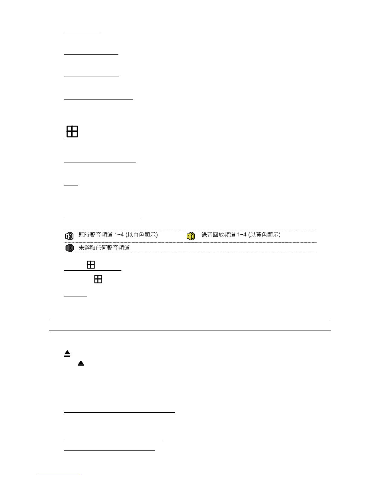
開始使用之前
2
6) PLAY (播放)
按 PLAY 立即回放最近一筆的錄影資料。
7) SLOW (慢速回放)
在回放模式下,按 SLOW 進行慢速回放。
8) ZOOM (數位變焦)
按 ZOOM 在 FRAME 或 FIELD 錄影模式下放大選取頻道的畫面。
9) SEQ (全螢幕跳台顯示)
按 SEQ 依序全螢幕顯示每個頻道,從 CH1 開始。顯示最後一個頻道後,就會從 CH1 開
始從頭再來。若要結束此模式,請再按一次 SEQ。
10)
按此鍵可顯示 4 分割頻道顯示模式。
11) CH1 ~ 16 / 1 ~ 8 / 1 ~ 4
按頻道編號選取想要全螢幕顯示的頻道。
12) 搜尋
按 SEARCH 進入時間搜尋清單。設定想要的時間,然後選擇開始回放指定時間內的錄影
資料。
13) AUDIO (SLOW + ZOOM)
按 SLOW + ZOOM 選取即時聲音頻道或錄音頻道。
即時聲音頻道 1~4 (以白色顯示) 錄音回放頻道 1~4 (以黃色顯示)
未選取任何聲音頻道
14) P.T.Z. ( + SEQ) (
僅限特定型號
)
同時按住 + SEQ 可進入 / 跳出 PTZ 控制模式。
15) USB 埠
前面板有內建兩個 USB 埠,可用來連接 USB 滑鼠進行 DVR 操作,或者連接 USB 隨身
碟進行影像備份。
註: 前面板的 USB 埠不得同時連接兩隻 USB 滑鼠或兩台 USB 隨身碟。
如需得知相容 USB 隨身碟列表,請參閱第 45 頁的「附錄 2 相容 USB 隨身碟品牌」。
16) (
僅限特定型號
)
按 “ ” 開啟 / 關閉 DVD 燒錄機。
1.3 背板
1) 75Ω / HI-IMPEDANCE (
僅限特定型號
)
若使用 Loop 功能,請切換到 HI-IMPEDANCE。若沒有使用 Loop 功能,請切換到 75Ω。
2) VIDEO IN (1 ~ 16 / 1 ~ 8 / 1 ~ 4):連接攝影機的影像接頭。
VIDEO LOOP (1 ~ 16 / 1 ~ 8):影像輸出接頭。(
僅限特定型號
)
Page 78
開始使用之前
3
註: DVR 會自動偵測攝影機的影像系統,所以請務必先將攝影機接妥並上電,再將 DVR 上電。
3) AUDIO IN (1 ~ 4)
連接攝影機的聲音接頭 (若攝影機支援錄音的話)。
註: 要備份影音資料,請先確認攝影機有支援收音功能,並連接到正確的影像頻道和聲音頻
道。例如,聲音頻道 1 的聲音資料會與影像頻道 1 的影像資料錄在一起。
4) AUDIO OUT
連接到單聲道輸出的擴音器。
註: 如需得知您 DVR 支援的聲音輸出資訊,請參閱其規格表。
5) MONITOR
連接 CRT 螢幕之用。
註: 若 MONITOR 和 VGA 都接了螢幕,在 DVR 開機時按面板左鍵◄可強制藉由 MONITOR
進行影像輸出。詳情請參閱第 15 頁的「4.5 影像輸出切換」。
6) CALL (
僅限特定型號
)
連接到跳台輸出專用的螢幕。
7) VGA
直接連接至 LCD 螢幕以輸出影像。
註: 若 MONITOR 和 VGA 都接了螢幕,在 DVR 開機時按面板右鍵►可強制藉由 VGA 進行
影像輸出。詳情請參閱第 15 頁的「4.5 影像輸出切換」。
8) IR (
僅限特定型號
)
連接到 IR 遙控器的接收延長線。
9) EXTERNAL I/O
此埠是用來連接外部設備 (例如快速球攝影機或警報感應器等等)。
詳細的 I/O 埠的 PIN 解說,請參閱第 50 頁的「附錄 6 PIN 腳解說」。
10) LAN
以網路線來連上網際網路。
11) DC 19V
連接到電源變壓器 (包裝盒內附)。
12)
電源開關
切換到 \ 開機,切換到 | 關機。
Page 79
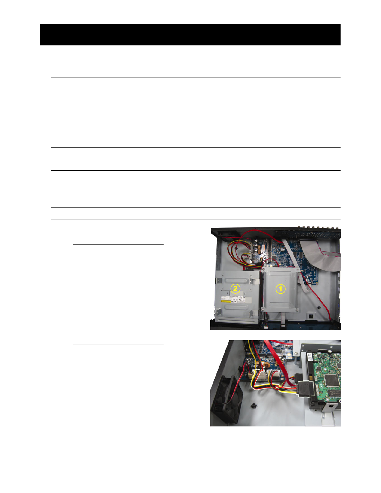
連接與設定
4
2. 連接與設定
DVR 開機之前,請先確認是否已裝入硬碟,而且最少已接妥一隻攝影機。詳情請參閱以下
說明。
註: DVR 會自動偵測連接攝影機的影像系統(NTSC 或 PAL)。為確保系統偵測無誤,在 DVR
開機之前,請先確定攝影機已接到 DVR 並上電。
2.1 SATA 硬碟安裝
在 DVR 開機之前,請務必先安裝好 SATA 硬碟。
註: 在 DVR 初次開機並設定好日期和時間後,建議清除硬碟資料,以確保新的錄影資料不會
與之前儲存在同顆硬碟的其他資料混在一起。詳情請參閱第 8 頁的「2.5 清除硬碟資料」。
16 路 & 8 路機種
步驟 1: 鬆開螺絲打開 DVR 上蓋。
註: DVR 上蓋是由金屬製成,在打開上蓋時請小心。
步驟 2: DVR 有兩個硬碟支架,如右圖所示。
2-1 將硬碟安裝到第一個支架
取下支架,然後將支架側邊的螺絲孔與硬碟
螺絲孔對齊。請確認硬碟的 PCB 面是朝上
的。
將硬碟固定在支架上,然後接妥電源線和資
料排線。接著,將支架裝回 DVR。
2-2 將硬碟安裝到第二個支架
接妥硬碟電源線和資料排線。
在接硬碟電源線時,確認該電源線有穿過
DVD 燒錄機的電源線,以避免硬碟電源線
不會卡到風扇運作。
將支架側邊的螺絲孔與硬碟兩側的螺絲孔
對齊。請確認硬碟的 PCB 面是朝上的。接
著,將硬碟鎖住固定在支架上。
註: 如需得知 DVD 燒錄機的安裝方式,請參閱第 53 頁的「附錄 7 DVD 燒錄機安裝」。
Page 80
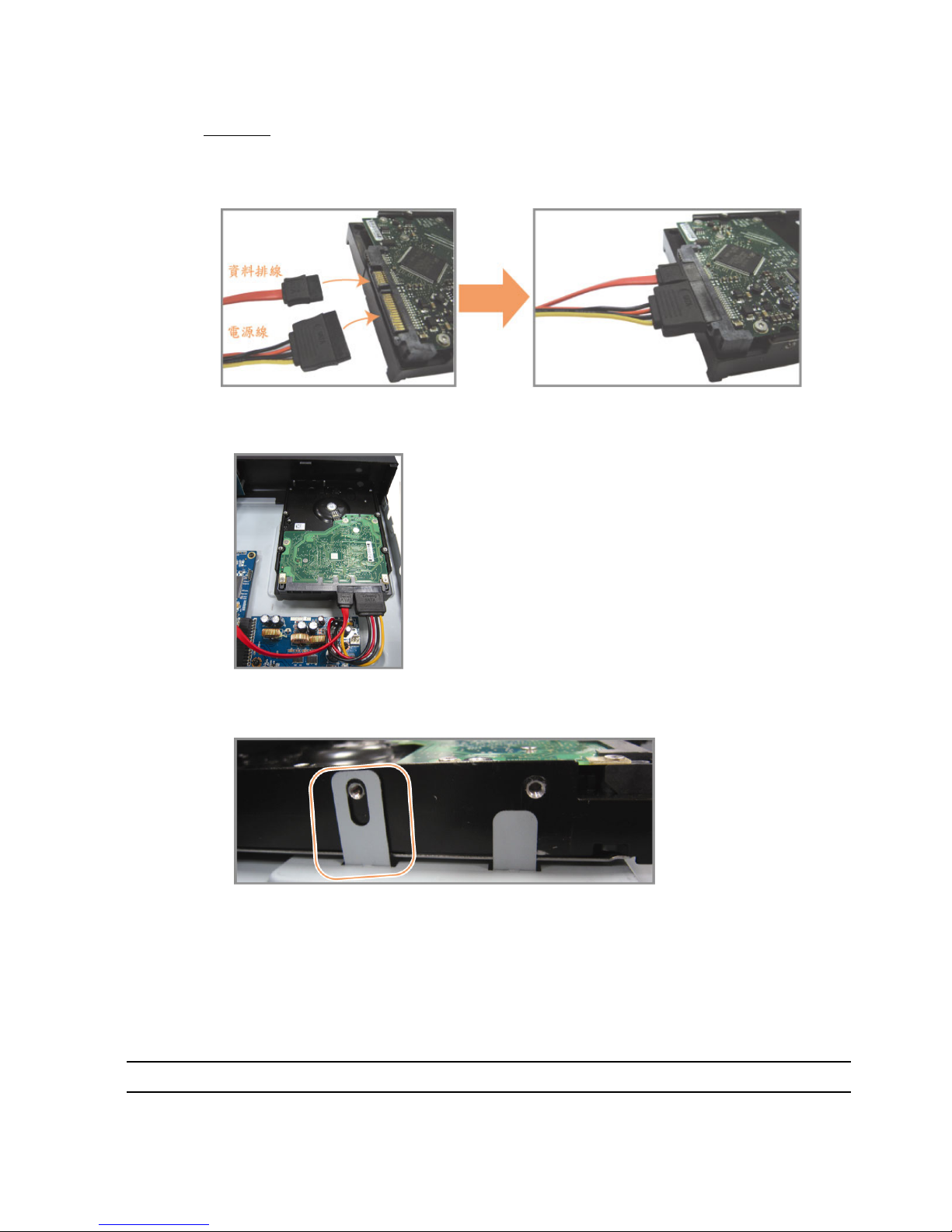
連接與設定
5
步驟 3: 裝回 DVR 上蓋,然後鎖回在步驟 1 鬆開的所有螺絲。
4 路機種
步驟 1: 鬆開 DVR 上蓋的螺絲,然後打開 DVR 上蓋。找到 DVR 內的硬碟支架。
步驟 2: 將相容硬碟連接到電源接頭和資料排線接頭。
步驟 3: 將硬碟的 PCB 面朝上,然後再將硬碟放到支架中間,如下所示。
確認硬碟另一面有接觸到 DVR 底座,以確保散熱無虞。
步驟 4: 將硬碟兩側的螺絲孔對準支架的螺絲孔 (如下所示),然後使用隨附螺絲將硬碟鎖
在支架上。
步驟 5: 裝回 DVR 上蓋,然後鎖回在步驟 1 鬆開的所有螺絲。
2.2 攝影機連接
在 DVR 開機之前,請先接妥攝影機並上電。請使用指定的電源供應器連接攝影機。之後,
再用同軸電纜或接好 BNC 接頭的 RCA 線,連接攝影機和 DVR 的影像插孔。
註: 關於 DVR 影像輸入埠的詳細資訊,請參閱第 1 頁的「1.2 前面板」。
Page 81
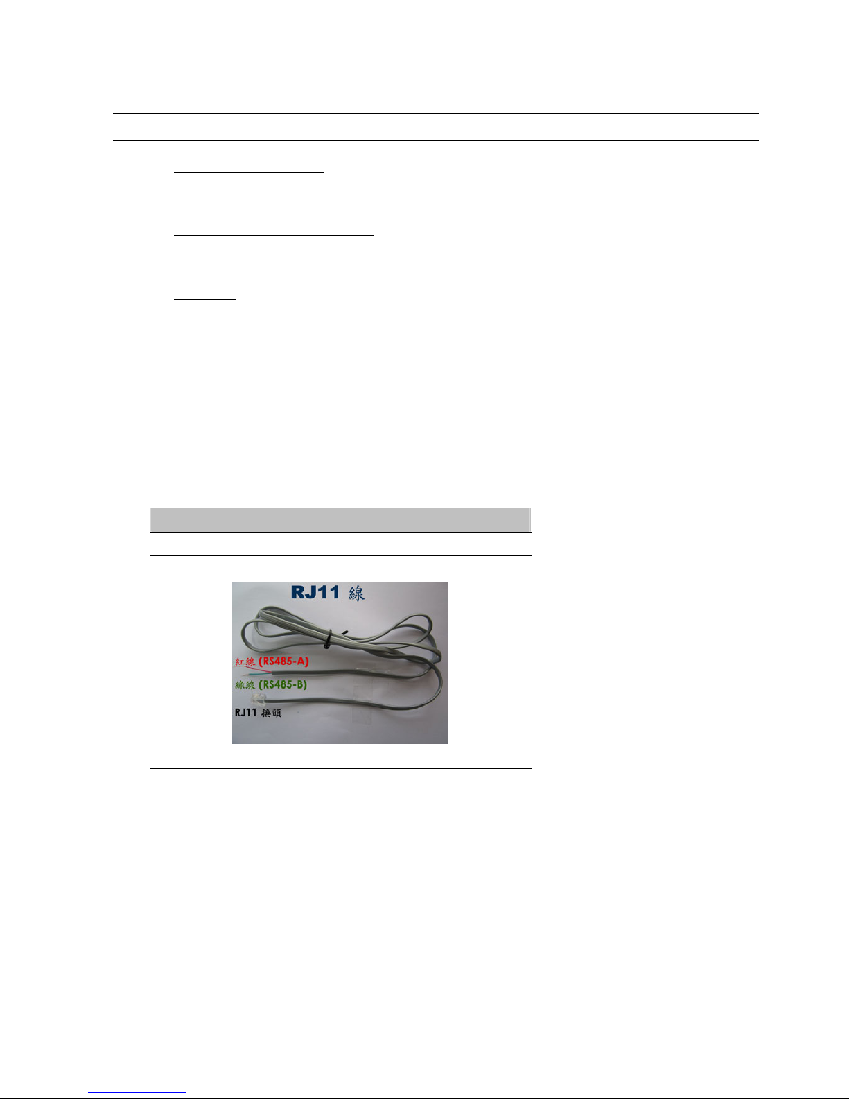
連接與設定
6
2.2.1 一般攝影機連接
註: 相關攝影機連接細節,請參閱其各自的使用說明書。
1) 連接 DVR 影像輸入埠
用同軸電纜或接好 BNC 接頭的 RCA 線,連接攝影機和 DVR 的影像插孔。
2) 連接 DVR 音源輸入埠 (選用)
用同軸電纜或接好 BNC 接頭的 RCA 線,連接攝影機和 DVR 的音源插孔。
3) 連接電源
使用指定的電源供應器連接攝影機,並插入電源插座。
2.2.2 PTZ 攝影機連接 (
僅限特定型號
)
以下說明是以連接本公司自家 PTZ 攝影機為例。
有關控制 PTZ 攝影機的 DVR 設定,請參閱第 21 頁的「5.5 PTZ 攝影機設定」。關於 PTZ
攝影機控制和操作的詳細資訊,請參閱其各自的使用說明書。
RJ11 線
RS485-A:紅線
RS485-B:綠線
RJ11
線並未隨附產品提供。
步驟 1:取得一條長度適當的 RJ11 連接線。
RJ11 連接線內的線路配置 (RS485-A / RS485-B) 可能會與此處所述不同。若您
在連接後仍無法控制 DVR,請將線路交換連接試試。
步驟 2:刮除 RJ11 連接線一端的絕緣膜。
刮除 RJ11 連接線一端的絕緣膜並找出 RS485-A 和 RS485-B 線,然後把那兩條
線的絕緣膜刮掉露出裸線。
Page 82

連接與設定
7
步驟 3:將 RJ-11 連接線和快速球攝影機的 RS485-A 和 RS485-B 線纏在一起。
將 RJ11 連接線的紅線,與所有攝影機的 RS485-A 線纏在一起。然後,將 RJ11
連接線的綠線,與所有攝影機的 RS485-B 線纏在一起。使用絕緣膠帶將纏在一
起的裸線包覆起來,以達到保護的效果。
步驟 4:將 RJ11 接頭插入 DVR。
將 RJ11 連接線的 RS485-A (紅色) 和 RS485-B (綠色) 線焊到 D-Sub 接頭相對
應的 PIN 腳上。
如需得知 DVR 的 PIN 配置說明,請參閱第 50 頁的「附錄 6 PIN 腳解說」。詳情
請洽您的安裝商。
步驟 5:在 DVR 進行快速球攝影機設定。
進入進階設定 l 外接裝置設定來設定快速球攝影機。
a) 選擇 PTZ。
b) 設定 ID 值,此值必須與快速球攝影機本身設定的值相同。攝影機的預設 ID 為
000。
c) 將通訊協定設為一般。
d) 設定鮑率值,此值必須與快速球攝影機本身設定的值相同。攝影機的預設鮑率
為 2400。
進階選單
攝影機設定 CH1 CH2 CH3 CH4 CH5 CH6 CH7 CH8 CH9 CH10 CH11 W
X
偵測設定 裝置 PTZ
警示音設定 ID 000
網路設定 通訊協定 一般
網路對時設定 鮑率 2400
顯示設定
錄影設定
外接裝置設定
離開
2.3 DVR 開機
此設備操作必須使用製造者所標示的電源供應器類型。將指定的 AC 電源線接到變壓器,
並將電源插頭插入電源插座。電源 LED 顯示燈會亮。
註: 在 DVR 開機之前,請先確認攝影機已接妥並上電,以確保攝影機影像系統偵測無誤。
註: 為確保 DVR 可以持續正確運作,建議可視需要加上 UPS (不斷電系統) 較能保護好您的
設備持續運作。UPS 為選購配備。
Page 83
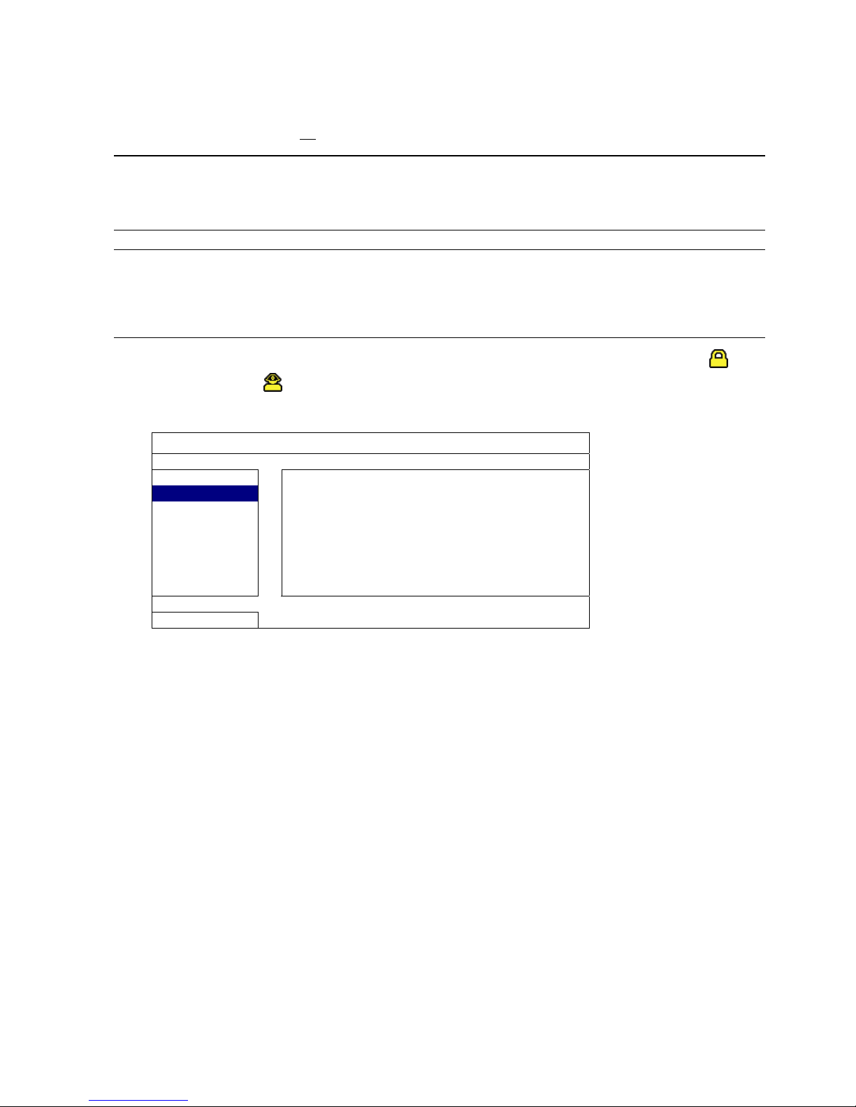
連接與設定
8
2.4 日期與時間設定
在操作 DVR 之前,請先設定 DVR 的日期與時間。
註: 請勿在錄影時修改日期和時間;否則,錄影資料會錯亂,而且無法依時間來搜尋想要備份
的資料。若修改了日期和時間,建議先將硬碟資料清除後再重新錄影,以免造成錄影時間
錯亂。
註: 若為初次使用 DVR,請在設定好日期與時間後,將 DVR 連續上電至少 48 小時。此舉可
確保 DVR 時間在斷電後不會重設。若 DVR 時間在斷電 (例如:停電) 後重設,這是因為
DVR 電池電量不足或已耗盡所致。請依第 49 頁的「附錄 5 更換 DVR 電池」說明來更換
電池。
按右鍵跳出密碼輸入視窗來輸入 DVR 密碼。預設管理者密碼為 0000。狀態會從 (按
鍵上鎖) 切換成 (管理者)。然後按右鍵顯示主目錄選單,並選擇快速設定 時間設
定來設定日期和時間。
快速設定
一般設定
日期 2009 / 11 / 17
時間設定
時間 15 : 35 : 53
離開
2.5 清除硬碟資料
在 DVR 初次開機並設定好日期和時間後,建議清除硬碟資料,以確保新的錄影資料不會
與之前儲存在同顆硬碟的其他資料混在一起。
按右鍵顯示主目錄選單,然後選擇系統資訊 系統資訊 清除硬碟。硬碟資料清除後,
DVR 會重新啟動。
Page 84

連接與設定
9
系統資訊
工具
鮑率 2400
系統資訊
主機 ID 000
USB 備份
R.E.T.R. 延遲(分) 5
光碟備份
按鍵鎖 (秒) 停用
清除硬碟 HDD-0
回復預設值 送出
遙控 ID 000
序列裝置類別 RS485
影像格式 NTSC
版本 1019-1008-1010-1010
離開
2.6 密碼設定
按右鍵顯示主目錄選單,然後選擇系統資訊 工具來變更 DVR 密碼。
使用權限共有兩種:管理者和操作者。詳情請參閱第 15 頁的「4.4 切換使用權限」。
系統資訊
工具
多國語言 繁體中文
系統資訊
管理者密碼 設定
USB 備份
操作者密碼 設定
光碟備份
升級 送出
離開
Page 85
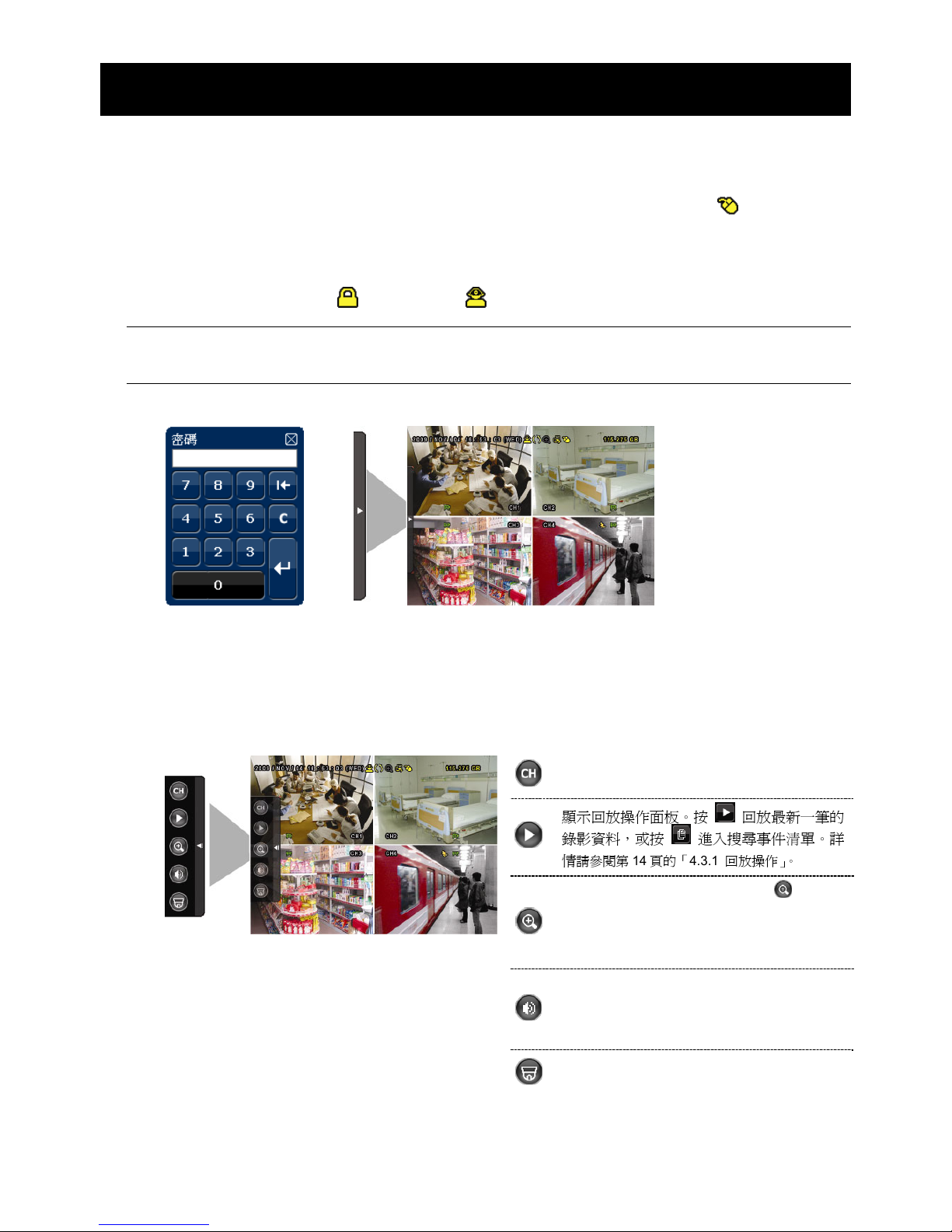
圖形化介面與 USB 滑鼠控制簡介
10
3. 圖形化介面與 USB 滑鼠控制簡介
3.1 連接 USB 滑鼠
將 USB 滑鼠插入 DVR 前面板的 USB 埠,然後等到螢幕出現滑鼠圖示 ( ),表示已正確
偵測到 USB 滑鼠。
移動滑鼠即會出現密碼輸入視窗,要求你輸入 DVR 密碼。預設的管理者密碼為 0000。輸
入後,DVR 狀態會從 (上鎖) 變成 (管理者),螢幕左側會出現快速選單列。
註: DVR 支援兩種使用者權限,使用者可以在主目錄選單的系統資訊 工具裡進行設定。
詳情請參閱第 22 頁的「5.6.1 密碼設定」。
密碼輸入 快速選單列:收合
3.2 快速選單列
將滑鼠移到箭號即可展開快速選單列,顯示以下五種功能:
快速選單列:展開
顯示頻道切換面板,讓使用者選擇想要切換的
頻道。
詳情請參閱第 11 頁的「3.2.1 頻道切換」。
顯示回放操作面板。按 回放最新一筆的
錄影資料,或按
進入搜尋事件清單。詳
情
請參閱第 14 頁的「4.3.1 回放操作」。
先切換到想要的頻道,然後再按 放大影
像。在放大模式下,按住並拖曳螢幕左下角的
紅框可移到想要查看的位置。若要退出此模
式,請按 7。
選取想要的聲音頻道。
在即時畫面下,只能選擇收聽即時聲音。
在回放模式下,可以選擇收聽即時聲音或錄
音。
進入 PTZ 模式並顯示 PTZ 攝影機控制面板。
詳情請參閱第 11 頁的「
3.2.2 PTZ 控制面板」。
Page 86
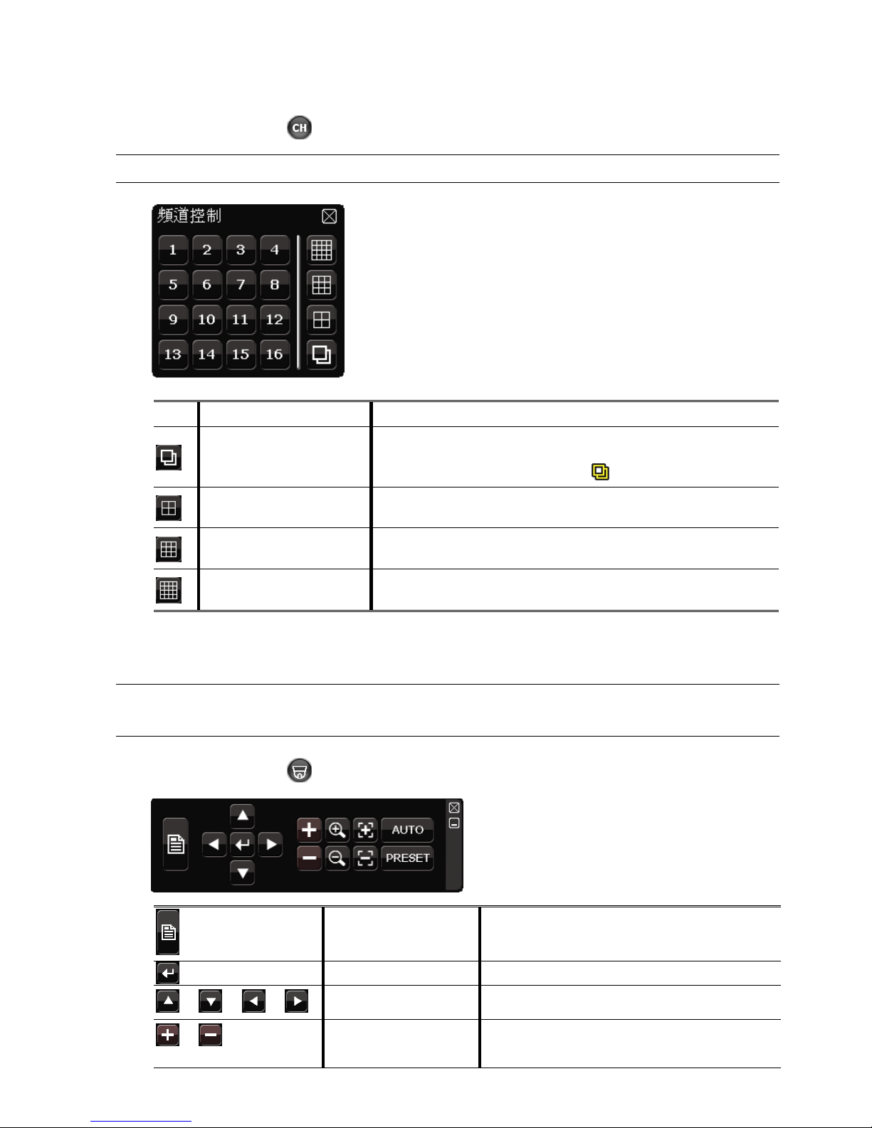
圖形化介面與 USB 滑鼠控制簡介
11
3.2.1 頻道切換
在快速選單列上按 會顯示以下畫面:
註: 可用按鈕須視各型號而定。
1~16
影像頻道
切換並全螢幕顯示想要的頻道。
全螢幕跳台
依序全螢幕顯示每個頻道,從 CH1 開始。顯示最後一個頻道後,
就會從 CH1 開始從頭再來。
啟動此功能時,螢幕狀態列會顯示
。
四分割跳台
按此鍵可顯示 4 分割頻道顯示模式。
九分割跳台
按此鍵可顯示 9 分割頻道顯示模式。
16 分割跳台
按此鍵可顯示 16 分割頻道顯示模式。
3.2.2 PTZ 控制面板 (
僅限特定型號
)
註: 在 PTZ 控制模式下,DVR 有支援滑鼠 hot point 操作攝影機,只要在螢幕上點擊想要移
動的目標位置,攝影機即會移到該位置。
在快速選單列上按 會顯示以下畫面:
攝影機選單
進入 / 跳出攝影機目錄選單。
有關攝影機目錄選單的詳細資訊,請參閱其各自
的使用說明書。
輸入 / 確認
確認選取項目 / 進入選取目錄選單。
/ / /
上 / 下 / 左 / 右
上下左右移動攝影機鏡頭,或者變更設定。
/
影像放到最大 /
恢復原始大小
按一下將影像放到最大 / 恢復影像原始大小。
Page 87
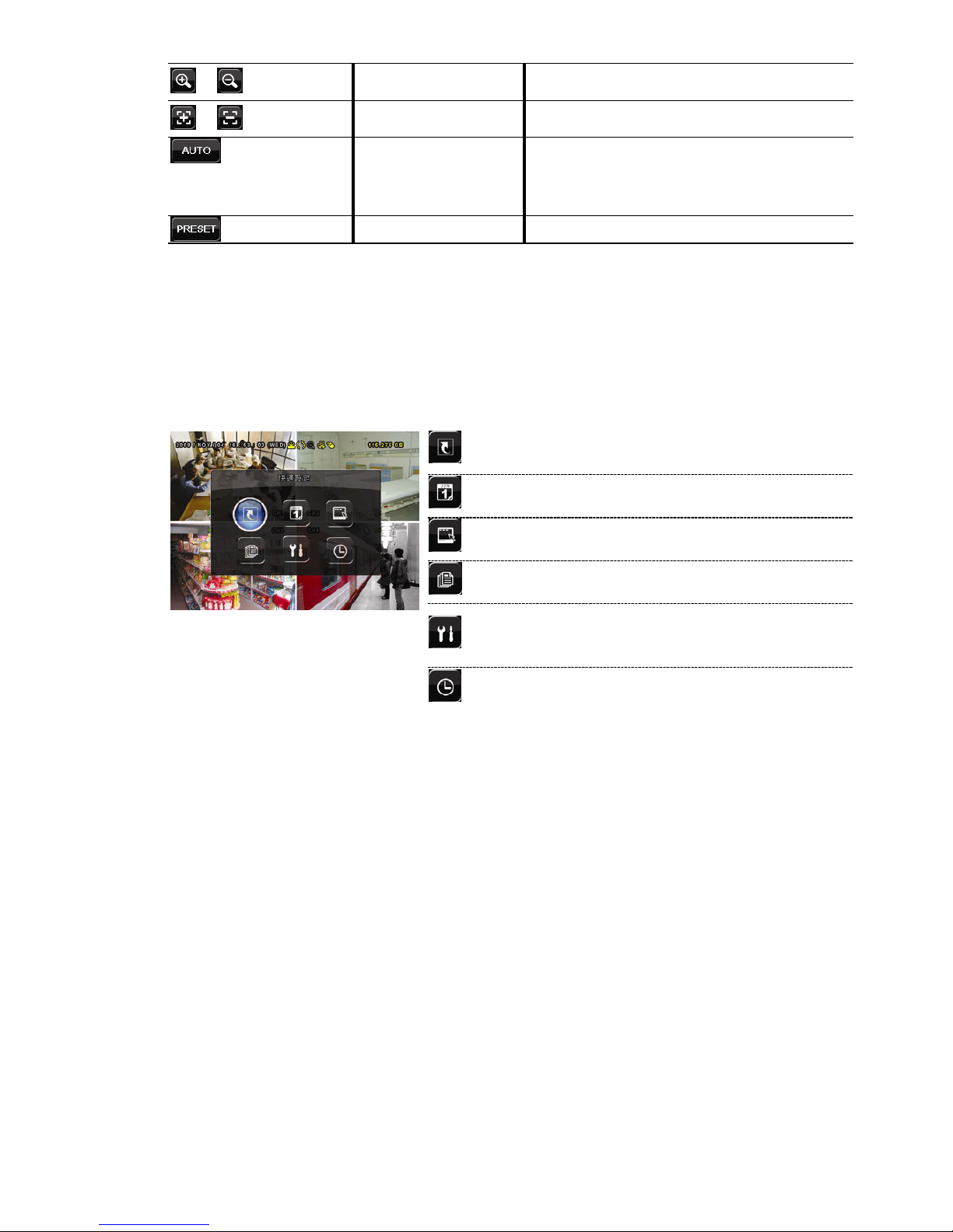
圖形化介面與 USB 滑鼠控制簡介
12
/
影像放大 / 影像縮小
按一下放大 / 縮小影像。
/
近距離 / 遠距離對焦
按一下調整影像的焦距。
自動模式
按一下啟動 PTZ 攝影機的自動巡邏功能。
在啟動此功能之前,請先設定啟動此功能時會作
用的巡邏功能。詳情請參閱 PTZ 攝影機的使用
說明書。
預設點
輸入您要觀看的預設點。
3.3 主目錄選單
在螢幕任一處按右鍵即可顯示主目錄選單,再按一下即可退出。
有關 DVR 目錄完整架構,請參閱第 47 頁的「附錄 4 主目錄選單架構」。
主目錄選單
快速選單
設定狀態顯示、影像設定,以及日期和
時間。
日期設定 設定日期顯示和日光節約時間。
系統資訊 設定系統相關配置。
事件資訊 進入事件搜尋選單。
進階選單
進入攝影機設定、偵測設定、警示音設
定、網路設定、網路對時設定、顯示設
定、錄影設定和外接裝置設定目錄。
預約設定 設定預約錄影或預約偵測錄影。
Page 88
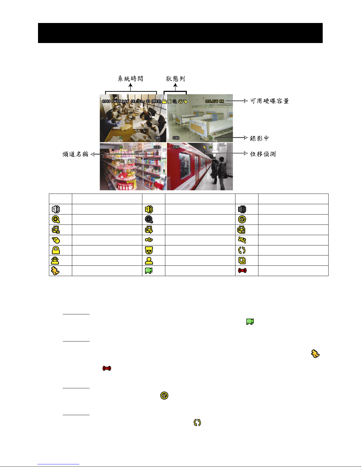
基本操作
13
4. 基本操作
4.1 即時畫面
圖示 功能 圖示 功能 圖示 功能
即時聲音頻道 (1~4)
錄音回放頻道 (1~4)
未選取聲音頻道
數位變焦開啟
數位變焦關閉
預約錄影
無網路連線
網際網路連線
區域網路連線
USB 滑鼠連接
USB 隨身碟 / 裝置連接
沒有連接任何 USB 裝置
按鍵鎖
PTZ 模式開啟
硬碟覆寫
管理者
操作者
全螢幕跳台
位移偵測
錄影
警報
4.2 錄影圖示
1) 手動錄影
根據預設,當 DVR 開機且有安裝硬碟時,就會啟動手動錄影 (
)。
2) 事件錄影
當位移偵測或警報開啟,且出現位移偵測或警報事件時,螢幕就會顯示位移偵測圖示 ( )
或警報圖示 ( )。
3) 預約錄影
當預約錄影啟動時,螢幕會出現 圖示。
4) 硬碟覆寫
硬碟覆寫功能是預設為開啟,且螢幕會顯示
圖示。
Page 89
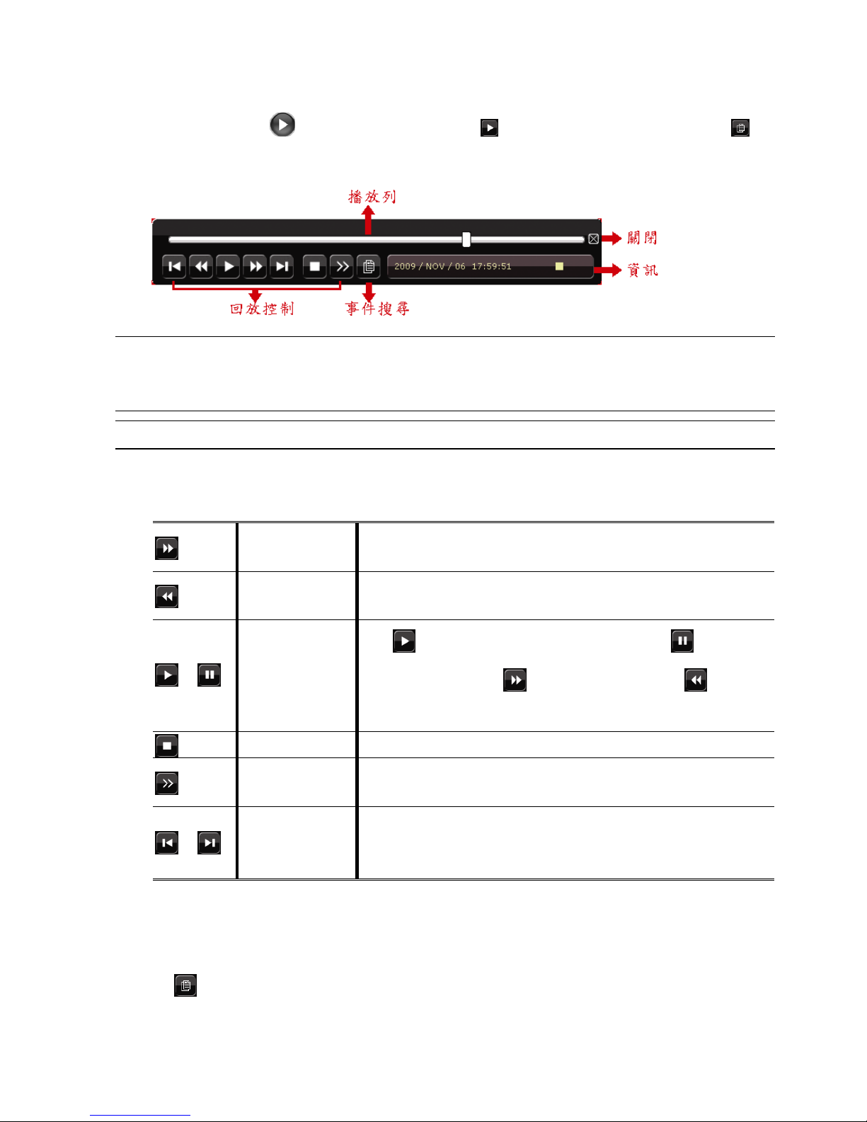
基本操作
14
4.3 影像回放
在快速選單列按 可顯示回放操作面板。按 回放最新一筆的錄影資料,或按 進
入搜尋事件清單。
註: 若要能正常回放錄影檔案,請至少必須錄超過 8192 張畫面。如果您尚未錄滿 8192 畫面
就進行回放動作,DVR 將會停止回放。例如,如果您將 IPS 設為 30,若要正常回放檔案,
則錄影時間至少必須超過 273 秒 (8192 張影像 / 30 IPS)。
註: 在回放影像時,螢幕會顯示錄影的影像大小 (FRAME、FIELD 或 CIF)。
4.3.1 回放操作
快轉
加快回放速度。按一次以 4 倍的速度回放快轉畫面,按兩
次以 8 倍的速度 … 以此類推。
倒轉
增加倒轉速度。按一次以 4 倍的速度倒轉畫面,按兩次以
8 倍的速度 … 以此類推。
/
播放 / 暫停
按 立即回放最近一筆的影像資料,按 即暫停。
在暫停時,按一次
可前進一張影像,按 倒轉一
張影像。
停止
停止影像回放。
慢速回放
按一下以 1/4X 速度慢速回放錄影影片,按兩下以 1/8X
速度慢速回放。
/
前一個 /
下一個小時
按一下可跳至下一個 / 前一個小時 (例如 1:00 ~ 12:00
或 14:00 ~ 15:00),並立即播放在該時段中最早的錄影資
料。
4.3.2 事件搜尋
按 可依事件快速搜尋錄影資料:錄影清單 / 位移事件清單 / 警報事件清單 / 時間清
單,或者選擇全部事件清單顯示所有事件記錄。
Page 90
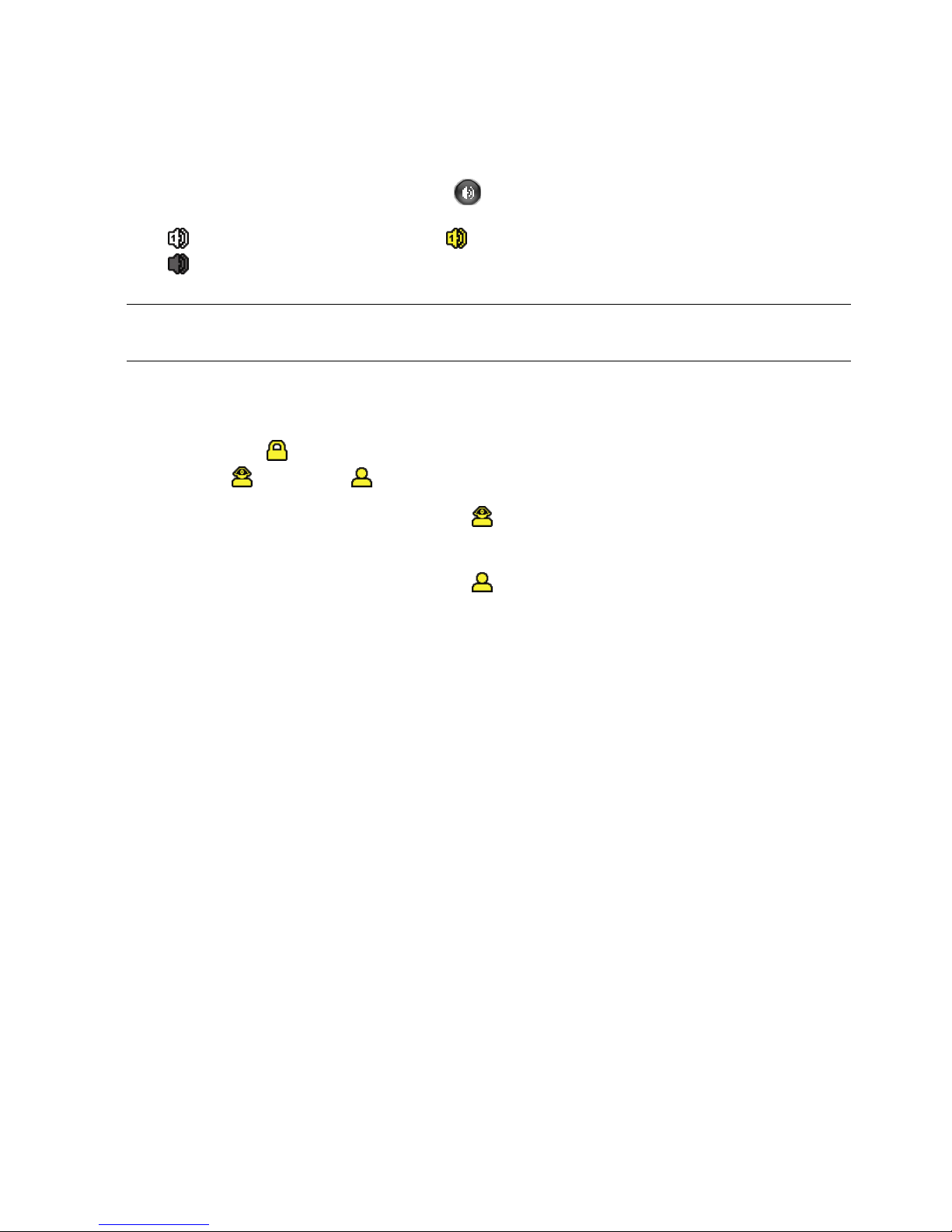
基本操作
15
若要進行時間搜尋,請選擇快速搜尋。設定想要的時間,然後選擇開始回放指定時間內的
錄影資料。
4.3.3 錄音回放
在回放時,視需要按快速目錄列上的 來選取要聽聲音頻道 1~4 的即時聲音或錄音。
即時聲音頻道 1~4 (以白色顯示) 錄音回放頻道 1~4 (以黃色顯示)
未選取任何聲音頻道
註: 要備份影音資料,請先確認攝影機有支援收音功能,並連接到正確的影像頻道和聲音頻
道。例如,聲音頻道 1 的聲音資料會與影像頻道 1 的影像資料錄在一起。
4.4 切換使用權限
當按鍵上鎖 ( ) 時,移動 USB 滑鼠即會顯示密碼輸入視窗。DVR 支援兩種使用權限:
管理者 ( ) 和操作者 ( )。
若輸入管理者密碼,螢幕狀態列會顯示 ,使用者可以執行所有操作。預設的管理者密
碼為 0000。
若輸入操作者密碼,螢幕狀態列會顯示 ,且使用者無法進入主目錄選單。操作者權限
必須進入主目錄選單的系統資訊 工具中設定。
若要切換這兩種使用權限,先點一下目前的權限圖示進入按鍵鎖模式,然後再動一下滑鼠
顯示密碼輸入視窗,再輸入想要切換的使用權限密碼。
4.5 影像輸出切換
使用者無法同時連接 CRT 螢幕 (連接到 MONITOR) 和 LCD 螢幕 (連接到 VGA) 來顯示
影像。
預設的影像輸出設定為自動,即 DVR 會自動偵測影像輸出來源。若 VGA 和 MONITOR 都
有接螢幕,預設會選取 VGA 來進行影像輸出。
如何手動變更影像輸出設定:
若要強制透過 MONITOR 進行影像輸出,請在 DVR 開機時按面板左鍵 ◄。
若要強制透過 VGA 進行影像輸出,請在 DVR 開機時按面板右鍵 ►。
當您聽見一聲短嗶聲,表示設定已變更完成。
或者:
等到 DVR 開完機且初始化完成後,按右鍵進入主目錄選單,然後選擇進階選單 顯示
設定 顯示輸出位置。
選擇 VGA 切換影像輸出到連接的 LCD 螢幕,COMPOSITE 則是切換到連接的 CRT 螢幕。
Page 91

基本操作
16
之後 DVR 會重新啟動,以使變更生效。
進階選單
攝影機設定
去交錯 (
僅限特定型號
)
關閉
偵測設定
全螢幕跳台停留時間 (秒) 03
警示音設定
四分割跳台停留時間 (秒) (
僅限特定型號
) 03
網路設定
顯示隱蔽字樣 開啟
網路對時設定
剩餘硬碟空間顯示方式 硬碟大小
顯示設定
顯示輸出位置 自動
錄影設定
視窗透明度 200
外接裝置設定
離開
Page 92

常用功能
17
5. 常用功能
5.1 快速搜尋
按 DVR 面板上的 SEARCH 可進入時間搜尋選單如下:
快速搜尋
日期 2009 / 11 / 20
時間 15:17:57
硬碟 全部硬碟
搜尋 開始
1) 日期 / 時間
選擇您要搜尋資料的日期和時間。
2) 硬碟
選擇包含您要搜尋資料的硬碟,或者選擇全部硬碟。
3) 搜尋
按開始可開始搜尋並立即回放找到的影像資料。
5.2 錄影設定
5.2.1 錄影快速設定
按右鍵顯示主目錄選單,然後選擇快速設定 一般設定。
快速選單
一般設定
頻道名稱 開啟
時間設定
事件狀態 開啟
顯示日期 開啟
影像大小 CIF
畫質 超好
錄影張數 (IPS) 120
離開
1) 影像大小
選擇影像大小:FRAME、FIELD 或 CIF。
2) 畫質
選擇錄影畫質:超好、最好、高和一般。
Page 93

常用功能
18
3) 錄影張數 (IPS)
選擇手動錄影的 IPS (每秒播放圖像的速度)。
5.2.2 錄影詳細設定
按右鍵顯示主目錄選單,然後選擇進階選單 錄影設定。
註: 請勿在錄影時修改日期和時間;否則,錄影資料會錯亂,而且無法依時間來搜尋想要備份
的資料。若修改了日期和時間,建議先將硬碟資料清除後再重新錄影,以免造成錄影時間
錯亂。
進階選單
攝影機設定
手動錄影 開啟
偵測設定
事件錄影 開啟
警示音設定
預約錄影 開啟
網路設定
事件錄影張數 (每秒) 120
網路對時設定
預約錄影張數 (每秒) 120
顯示設定
警報前錄影 (
僅限特定型號
) 開啟
錄影設定
硬碟覆寫 開啟
外接裝置設定
事件觸發後全頻道錄影 關閉
保留資料天數 關閉
離開
1) 手動錄影
設定開啟或關閉手動錄影。
2) 事件錄影
設定開啟或關閉事件錄影。
3) 預約錄影
設定開啟或關閉預約錄影。
4) 事件錄影張數 (每秒)
選擇事件錄影 (警報或位移偵測觸發錄影) 的每秒錄影張數。
5) 預約錄影張數 (每秒)
選擇預約錄影 (依照設定排程啟動錄影) 的每秒錄影張數。
6) 警報前錄影 (
僅限特定型號
)
設定警報前錄影功能開/關 (開啟 / 關閉)。
當事件錄影功能與警報前錄影功能皆為啓動狀態下,若發生警報或位移偵測,DVR
會從觸發前 8MB 的檔案開始錄起。
7) 硬碟覆寫
開啟此功能後,當硬碟已滿時,便會開始覆寫之前的錄影資料。DVR 會清除 8MB 最
舊的錄影資料讓錄影繼續進行,不另行通知。
Page 94

常用功能
19
8) 事件觸發後全頻道錄影
選取在發生事件時,要全頻道錄影 (開啟),還是僅錄發生事件的頻道 (關閉)。
9) 保留資料天數
指定保留錄影資料的天數 (1~31 天),超過指定天數的錄影資料將會自動刪除。若要
關閉此功能,請選擇關閉。
5.3 預約設定
按右鍵顯示主目錄選單,然後選擇預約設定。
5.3.1 預約錄影
點選錄影設定。在預約錄影選擇開啟來啟用此功能,然後選擇啟動此功能的日子和時間。
預約設定
錄影設定 預約錄影 開啟
偵測設定 0 2 4 6 8 10 12 14 16 18 20 22 24
星期日
星期一
星期二
星期三
星期四
星期五
星期六
離開
X 軸
0 ~ 24 小時。每段時間間隔為 30 分鐘。
Y 軸
星期一 ~ 星期日。.
Page 95
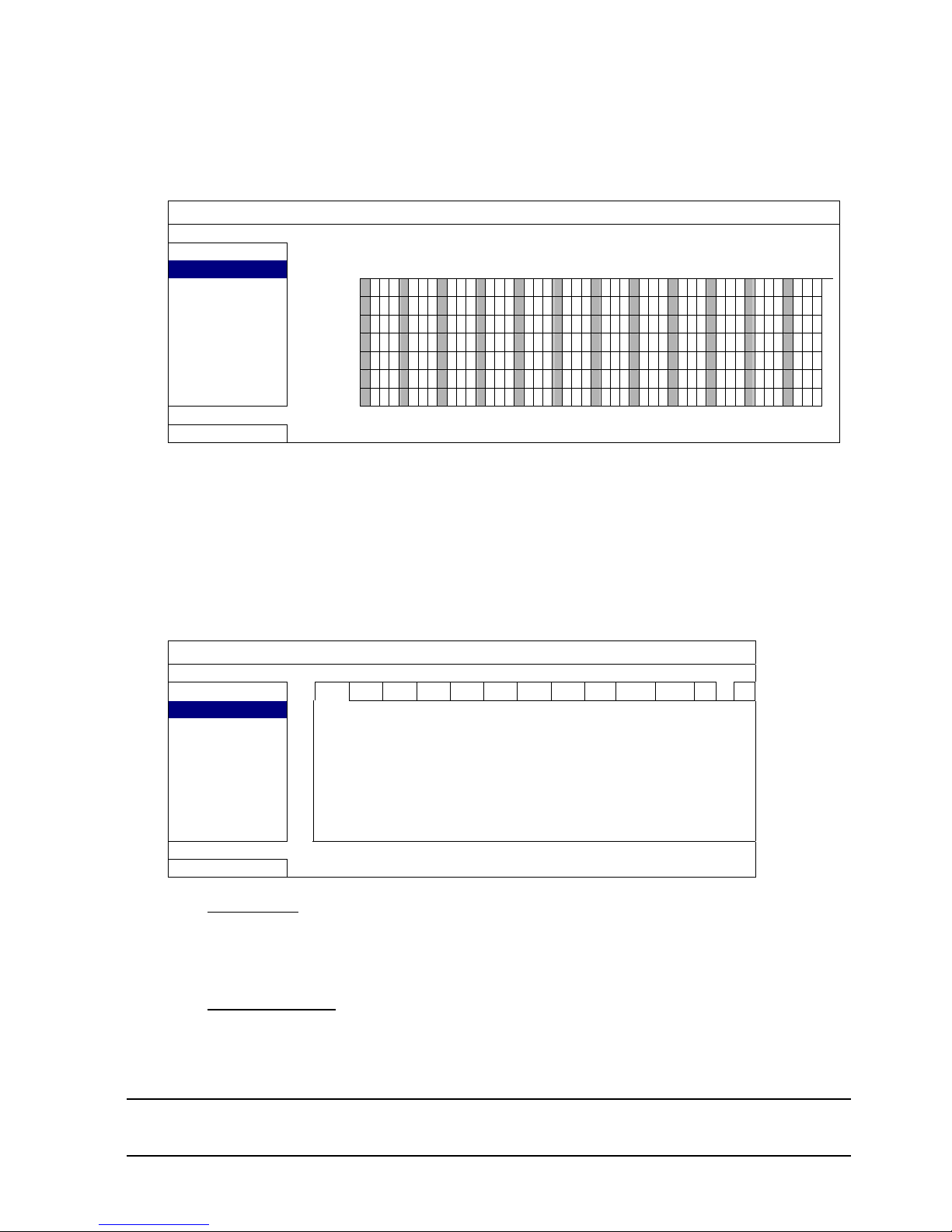
APPENDIX 7 DVD WRITER INSTALLATION
20
5.3.2 預約偵測錄影
點選偵測設定。在預約偵測錄影選擇開啟來啟用此功能,然後選擇啟動此功能的日子和時
間。
預約設定
錄影設定 預約偵測錄影 開啟
偵測設定 0 2
4 6 8 10 12 14
16 18 20
22
24
星期日
星期一
星期二
星期三
星期四
星期五
星期六
離開
X 軸
0 ~ 24 小時。每段時間間隔為 20 分鐘。
Y 軸
星期一 ~ 星期日。.
5.4 偵測設定
按右鍵顯示主目錄選單,然後選擇進階選單 偵測設定。
進階選單
攝影機設定 CH1 CH2 CH3 CH4 CH5 CH6 CH7 CH8 CH9 CH10 CH11 W X
偵測設定 LS 07
警示音設定 SS 03
網路設定 TS 02
網路對時設定 偵測 關閉
顯示設定 警報 關閉
錄影設定 移動區域設定 編輯
外接裝置設定
離開
1) LS (靈敏度)
“LS” 是比較兩張不同影像的靈敏度。數值越小,位移偵測的靈敏度越高。靈敏度最
高為 00,最低為 15。預設值為 07。
2) SS (空間靈敏度)
“SS” 是偵測螢幕上物體大小 (位移偵測的格子數目) 的靈敏度。數值越小,位移偵
測的靈敏度越高。
靈敏度最高為 00,最低為 15。預設值為 03。
註: SS 的預設值為 03,意指若被偵測的物體若在螢幕上超過 3 格,將會觸發位移偵測。故
SS 數值必須比您所設定的位移偵測格數還要少。
Page 96

APPENDIX 7 DVD WRITER INSTALLATION
21
3) TS (時間靈敏度)
“TS” 是物體持續觸發位移偵測的時間長短的靈敏度。數值越小,位移偵測的靈敏度
越高。
靈敏度最高為 00,最低為 15。預設值為 02。
4) 偵測
選擇是否要啟動選取頻道的位移偵測功能 (開啟/關閉)。
5) 警報
視安裝需求選擇 N.C./ N.O。預設值為關閉。
6) 移動區域設定
按編輯設定位移偵測區域。
每隻攝影機的偵測區域皆可分為 16 * 12 個方格。粉紅色格子代表未被偵測的區域,
而透明的格子代表有偵測的區域。
5.5 PTZ 攝影機設定 (
僅限特定型號
)
按右鍵顯示主目錄選單,然後選擇進階選單 外接裝置設定。
進階選單
攝影機設定 CH1 CH2 CH3 CH4 CH5 CH6 CH7 CH8 CH9 CH10 CH11 W X
偵測設定 裝置 PTZ
警示音設定 ID 00
網路設定 通訊協定 一般
網路對時設定 鮑率 2400
顯示設定
錄影設定
外接裝置設定
離開
1) 裝置
PTZ 攝影機請選擇 PTZ。
2) ID
若有必要,按一下目前的 ID 進入設定 PTZ 攝影機 ID 畫面 (0 ~ 255)。
確認攝影機本身的 ID 和此處的設定相符,否則 DVR 將無法控制此裝置。
註: 如需得知各 PTZ 攝影機的預設 ID,請參閱其各自的使用說明書。
3) 通訊協定
選擇一般 (本品牌的通訊協定)、P-D (PELCO-D) 或 P-P (PELCO-P) 通訊協定。
4) 鮑率
選擇連接 PTZ 攝影機的鮑率 (2400 / 4800 / 9600 / 19200 / 57600 / 115200)。
確認攝影機本身的鮑率和此處的設定相符,否則 DVR 將無法控制此裝置。
Page 97
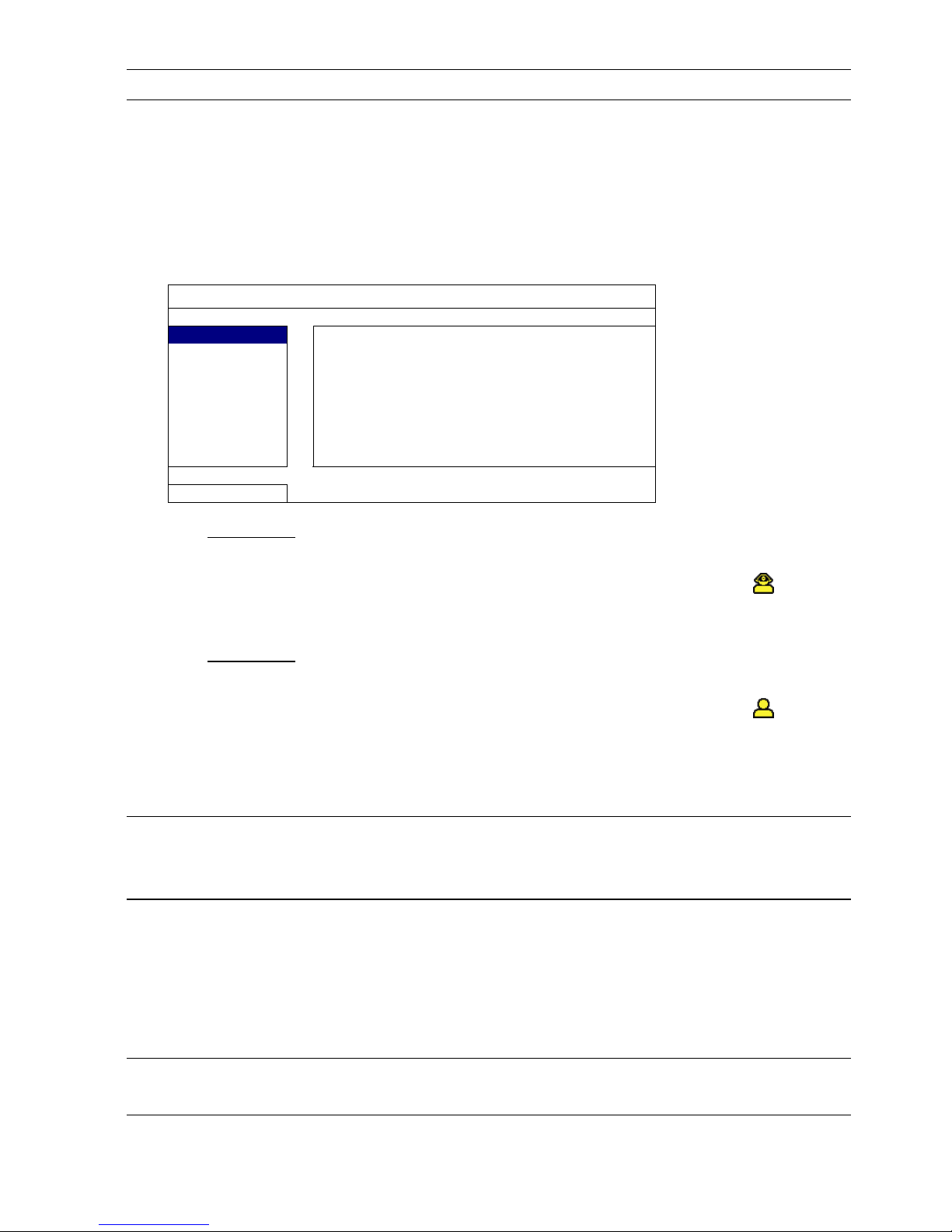
APPENDIX 7 DVD WRITER INSTALLATION
22
註: 如需得知各 PTZ 攝影機的預設鮑率,請參閱其各自的使用說明書。
5.6 系統設定
5.6.1 密碼設定
按右鍵顯示主目錄選單,然後選擇系統資訊 工具。
系統資訊
工具
多國語言 繁體中文
系統資訊
管理者密碼 設定
USB 備份
操作者密碼 設定
光碟備份
升級 送出
離開
1) 管理者密碼
按設定即可變更管理者密碼。預設的管理者密碼為 0000。
當系統提示您輸入 DVR 時,輸入管理者密碼後,螢幕狀態列就會出現 ,表示所
有操作皆可使用。
2) 操作者密碼
按設定即可設定或變更操作者密碼。 .
當系統提示您輸入 DVR 時,輸入操作者密碼後,螢幕狀態列就會出現 ,使用者
無法進入主目錄選單。
5.6.2 系統更新
註: 若您當前的 DVR 系統版本太舊,升級可能會導致清除所有硬碟資料。因此,在升級 DVR
系統之前,請先與您的安裝商或經銷商確認您當前的 DVR 系統版本,然後建立必要的影
像備份。
按右鍵顯示主目錄選單,然後選擇系統資訊 工具 升級。
將從安裝商或經銷商取得的升級檔儲存在相容的 USB 隨身碟內,然後插入前面板的 USB
埠。
然後,按送出開始進行升級。
註: 在使用 USB 隨身碟之前,請先使用您的電腦將 USB 隨身碟格式化成 FAT32 的格式。若
欲得知相容的 USB 隨身碟品牌,請參閱第 45 頁的「附錄 2 相容 USB 隨身碟品牌」。
Page 98

APPENDIX 7 DVD WRITER INSTALLATION
23
5.6.3 影像備份
按右鍵顯示主目錄選單,然後選擇系統資訊 USB 備份或光碟備份。
註: 光碟備份僅限特定型號才有。詳情請查閱您 DVR 的規格表。
將相容 USB 隨身碟插入前面板的 USB 埠,或者按 打開 DVD 燒錄機,然後放入 DVD-R
或 CD-R 光碟片。
註: 在使用 USB 隨身碟之前,請先使用您的電腦將 USB 隨身碟格式化成 FAT32 的格式。若
欲得知相容的 USB 隨身碟品牌,請參閱第 45 頁的「附錄 2 相容 USB 隨身碟品牌」。
系統資訊
工具
開始日期 2009 / 11 / 19
系統資訊
開始時間 08:30:21
USB 備份
結束日期 2009 / 11 / 19
光碟備份
結束時間 17:59:29
頻道 01 02 03 04
05 06 07 08
09 10 11 12
13 14 15 16
硬碟 全部硬碟
備份 送出
需要空間大小:554MB 送出
離開
可用空間:3,788.0MB
1) 開始日期 / 開始時間
選擇備份的開始日期和時間。
2) 結束日期 / 時間
選擇備份的結束日期和時間。
3) 頻道
點選想要備份的頻道。
4) 硬碟
選擇包含您要的影像資料的硬碟,或者選擇全部硬碟。
5) 備份
按送出開始備份。
6) 需要空間大小
若想在備份前得知備份影像檔的預估大小,請按送出開始計算。
Page 99

APPENDIX 7 DVD WRITER INSTALLATION
24
備份檔案回放
在備份檔案到 USB 隨身碟或光碟片時,會同時複製檔案播放軟體安裝
檔 PLAYER.EXE 到 USB 隨身碟中,且螢幕會顯示 CHECK PLAYER 訊息。
註: 一片 CD-R 或 DVD-R 可支援的備份檔案數量上限為 41。
將 USB 隨身碟插入電腦,或將 CD / DVD 光碟放入電腦。選取 PLAYER.EXE,
然後點兩下執行安裝。安裝完成後,點兩下備份下來的檔案即可直接在電腦播
放。請確認檔案備份是否成功。
註: 支援的電腦作業系統為 Windows 7、Vista、XP & 2000。
5.6.4 清除所有硬碟資料
按右鍵顯示主目錄選單,然後選擇系統資訊 系統資訊 清除硬碟。
系統資訊
工具
鮑率 2400
系統資訊
主機 ID 000
USB 備份
按鍵鎖 (秒) 停用
光碟備份
清除硬碟 HDD-0
回復預設值 送出
遙控 ID 000
序列裝置類別 RS485
影像格式 NTSC
版本 1010-1005-1006-1007
離開
選取想要清除資料的硬碟,然後按是確認,或否取消。
在以下情況下,建議使用者清除所有資料:
初次使用 DVR 時。此舉可確保新的錄影資料不會與之前儲存在相同硬碟內的其他資料混在
一起。
在錄影功能啟動時,變更 DVR 的日期和時間。否則,錄影資料會錯亂,而且無法依時間來
搜尋想要備份的資料。
5.7 網路設定
以下僅說明固定 IP 的設定方式。若要設定 PPPOE 和 DHCP,必須至 Video Viewer 進行
設定。
詳情請下載 Video Viewer 的使用說明書:
http://www.surveillance-download.com/user/CMS.pdf。
Page 100

APPENDIX 7 DVD WRITER INSTALLATION
25
固定 IP
進階選單
攝影機設定
網路類型 固定IP
偵測設定
IP 位址 192.168.001.010
警示音設定
閘道 192.168.001.254
網路設定
網路遮罩 255.255.255.000
網路對時設定
主要 DNS 168.095.001.001
顯示設定
次要 DNS 139.175.055.244
錄影設定
埠 0080
外接裝置設定
儲存網路設定 套用
離開
1) 網路類型
將網路類型設成固定 IP,然後設定 DVR 需要的所有資訊。
3) 網路資訊 (IP 位址 / 閘道 / 網路遮罩)
輸入您由網路 ISP 業者那得到的所有網路資訊。
4) DNS (主要 DNS / 次要 DNS)
輸入您由網路 ISP 業者那得到的 DNS (網域名稱伺服器) IP 位址。
5) 埠
有效數值範圍為 1 到 9999。預設值為 80。一般而言,HTTP 所使用的 TCP 埠多半
為 80 埠。然而有些情形下,建議您最好變更此埠值以增加彈性或安全性。
6) 儲存網路設定
按套用確認設定。
 Loading...