

Page 1
BEDIENUNGSANLEITUNG
INSTRUCTION MANUAL
MODE D’EMPLOI
ISTRUZIONI PER L’USO
VEILIGHEIDSVOORSCHRIFTEN
CONSEJOS DE SEGURIDAD
SIKKERHEDSOPLYSNINGER
SÄKERHETSFÖRESKRIFTER
TURVALLISUUDESTA
4-KANAL-DIGITAL-MULTIPLEXRECORDER
4 CHANNEL DIGITAL MULTIPLEXRECORDER
DMR-408A
Best.-Nr. 19.9400
®
Page 2

2
Bevor Sie einschalten ...
Wir wünschen Ihnen viel Spaß mit Ihrem neuen Gerät
von MONACOR. Dabei soll Ihnen diese Bedienungsanleitung helfen alle Funktionsmöglichkeiten kennen zu
lernen. Die Beachtung der Anleitung vermeidet außerdem Fehlbedienungen und schützt Sie und Ihr Gerät vor
eventuellen Schäden durch unsachgemäßen Gebrauch.
Den deutschen Text finden Sie auf den Seiten 4–22.
Before you switch on ... ...
We wish you much pleasure with your new unit by
MONACOR. With these operating instructions you will
be able to get to know all functions of the unit. By following these instructions false operations will be avoided,
and possible damage to you and your unit due to improper use will be prevented.
You will find the English text on the pages 4–22.
D
A
CH
GB
Avant toute mise en service ...
Nous vous remercions d’avoir choisi un appareil
MONACOR et vous souhaitons beaucoup de plaisir à
l’utiliser. Cette notice a pour objectif de vous aider à
mieux connaître les multiples facettes de l’appareil et à
vous éviter toute mauvaise manipulation.
La version française se trouve pages 24–42.
Prima di accendere ...
Vi auguriamo buon divertimento con il Vostro nuovo apparecchio MONACOR. Le istruzioni per l’uso Vi possono
aiutare a conoscere tutte le possibili funzioni. E
rispettando quanto spiegato nelle istruzioni, evitate di
commettere degli errori, e così proteggete Voi stessi, ma
anche l’apparecchio, da eventuali rischi per uso improprio.
Il testo italiano lo potete trovare alle pagine 24–42.
F
B
CH
I
Voordat u inschakelt ...
Wij wensen u veel plezier met uw nieuw toestel van
MONACOR. Lees de veiligheidsvoorschriften, alvorens
het toestel in gebruik te nemen. Door de veiligheidsvoorschriften op te volgen zal een slechte werking vermeden
worden, en zal een eventueel letsel aan uzelf en schade
aan uw toestel tengevolge van onzorgvuldig gebruik
worden voorkomen.
U vindt de veiligheidsvoorschriften op pagina 44.
Antes de cualquier instalación ...
Tenemos de agradecerle el haber adquirido un aparato
MONACOR y le deseamos un agradable uso. Por favor
lee las instrucciones de seguridad antes del uso. La
observación de las instrucciones de seguridad evita operaciones erróneas y protege Vd. y vuestro aparato contra todo daño posible por cualquier uso inadecuado.
Las instrucciones de seguridad se encuentran en la
página 44.
NL
B
E
Inden De tænder for apparatet ...
Vi ønsker Dem god fornøjelse med Deres nye MONACOR
apparat. Læs oplysningerne for en sikker brug af apparatet før ibrugtagning. Følg sikkerhedsoplysningerne for at
undgå forkert betjening og for at beskytte Dem og Deres
apparat mod skade på grund af forkert brug.
Sikkerhedsoplysningerne finder De på side 44.
Förskrift
Vi önskar dig mycket nöje med din nya enhet från
MONACOR. Läs gärna säkerhetsinstruktionerna innan
du använder enheten. Genom att följa säkerhetsinstruktionerna kan många problem undvikas, vilket annars kan
skada enheten.
Du finner säkerhetsinstruktionerna på sidan 45.
DK S
Ennen virran kytkemistä…
Toivomme, että uusi MONACOR-laitteesi tuo sinulle paljon iloa ja hyötyä. Ole hyvä ja lue käyttöohjeet ennen laitteen käyttöönottoa. Luettuasi käyttöohjeet voit käyttää
laitetta turvallisesti ja vältyt laitteen väärinkäytöltä.
Käyttöohjeet löydät sivulta 45.
FIN
Page 3
AUDIO
IN OUT
1234R
L
POWER
1
INPUT
LOOP
2 3 4 MAIN
CALL
EXTERNAL I/O
75Ω
HI
1ON234
Monitor
Call Monitor
Camera 1
Monitor Monitor Monitor
VIDEO
Main Monitor
AUDIO
Computer
Alarm Device
Alarm
Sensor 1
Alarm
Sensor 2
Alarm
Sensor 3
Alarm
Sensor 4
REMOTE
CONTROL
4 x ALARM IN
ALARM OUT
VIDEO
Camera 2
CCD CAMERA
Camera 3
CCD CAMERA
Camera 4
CCD CAMERA
CCD CAMERA
AUDIO
POWER
H-HOLD V-HOLD BRIGHT CONTRAST
Camera 1
POWER
H-HOLD V-HOLD BRIGHT CONTRAST
Camera 2
POWER
H-HOLD V-HOLD BRIGHT CONTRAST
Camera 3
POWER
H-HOLD V-HOLD BRIGHT CONTRAST
Camera 4
®
POWER
O
I
H-HOLD V-HOLD BRIGHT CONTRAST
Camera 1
Camera 2
Camera 3
Camera 4
POWER
H-HOLD V-HOLD BRIGHT CONTRAST
AUDIO
IN OUT
1234R
L
POWER
1
INPUT
LOOP
234MAIN
CALL
EXTERNAL I/O
75Ω
HI
1ON234
3
Digital Video Recorder
ALARM
TIMER
PLAY
HDD
Full
POWER
PAUSE/Up
STOP/ Down
FF
Right
REW
Left
REC
®
MENU ENTER SEARCH ZOOM
SLOW REC1 234
12345
1
2
3
6 7 8 9 10 11 12 13 14 15 16 17 18 19
20 21 22 23 24 25 26 27 28
Page 4

1 Übersicht der Bedienelemente und
Anschlüsse . . . . . . . . . . . . . . . . . . . . . . . . . 5
1.1 Frontseite . . . . . . . . . . . . . . . . . . . . . . . . . . . 5
1.2 Rückseite . . . . . . . . . . . . . . . . . . . . . . . . . . . 5
2 Hinweise für den sicheren Gebrauch . . . . 6
3 Anwendungsmöglichkeiten . . . . . . . . . . . . 6
4 Geräte anschließen . . . . . . . . . . . . . . . . . . 7
4.1 Video- und Audioeingänge . . . . . . . . . . . . . . 7
4.2 Video- und Audioausgänge . . . . . . . . . . . . .7
4.3 Alarm- und Steueranschlüsse . . . . . . . . . . . 7
4.3.1 Alarmeingänge . . . . . . . . . . . . . . . . . . . . . . 7
4.3.2 Alarmausgang . . . . . . . . . . . . . . . . . . . . . . 7
4.3.3 Anschluss eines Computers/Terminals . . . 7
5 Inbetriebnahme . . . . . . . . . . . . . . . . . . . . . . 8
5.1 Bedientasten sperren . . . . . . . . . . . . . . . . . . 8
6 Live-Überwachung . . . . . . . . . . . . . . . . . . . 8
6.1 Anzeigeformate wählen . . . . . . . . . . . . . . . . 8
6.1.1 Vollbild-Format . . . . . . . . . . . . . . . . . . . . . . 8
6.1.2 Mehrfachbild-Formate . . . . . . . . . . . . . . . . 8
6.1.3 Vergrößerung eines Bildausschnittes
(Zoom-Funktion) . . . . . . . . . . . . . . . . . . . . . 9
7 Aufnahme . . . . . . . . . . . . . . . . . . . . . . . . . . 9
7.1 Manuelle Aufnahme . . . . . . . . . . . . . . . . . . . 9
7.2 Timergesteuerte Aufnahme . . . . . . . . . . . . . 9
7.3 Alarmaufnahme . . . . . . . . . . . . . . . . . . . . . .9
7.4 Aufnahmestart durch den Bewegungs-
detektor . . . . . . . . . . . . . . . . . . . . . . . . . . . 10
8 Wiedergabe . . . . . . . . . . . . . . . . . . . . . . . . 10
8.1 Schneller Vor-/Rücklauf . . . . . . . . . . . . . . . 10
8.2 Langsamer Vor-/Rücklauf . . . . . . . . . . . . .10
8.3 Schrittweise Wiedergabe von
Einzelbildern im Pausenmodus . . . . . . . . . 10
8.4 Bestimmte Aufnahme suchen
und abspielen . . . . . . . . . . . . . . . . . . . . . . . 11
8.4.1 LASTRECORD
Wiedergabe der letzten Aufnahme . . . . . . 11
8.4.2 FULLLIST
Gesamtliste aller Aufnahmen . . . . . . . . . . 11
8.4.3 ALARM LIST
Liste aller Alarmaufnahmen . . . . . . . . . . . 11
8.4.4 MOTION LIST
Liste der detektorgestarteten
Aufnahmen . . . . . . . . . . . . . . . . . . . . . . . . 11
8.4.5 TIME SEARCH
Aufnahmesuche über Zeit-/
Datumsangabe . . . . . . . . . . . . . . . . . . . . . 12
9 Änderung der Betriebsparameter
über das Bildschirm-Menü . . . . . . . . . . . 12
9.1 Hauptmenü . . . . . . . . . . . . . . . . . . . . . . . . . 12
9.2 Menü TIMER . . . . . . . . . . . . . . . . . . . . . . . 13
9.3 Menü RECORD . . . . . . . . . . . . . . . . . . . . . 14
9.4 Menü CAMERA . . . . . . . . . . . . . . . . . . . . .14
9.4.1 Untermenü für den Bewegungsdetektor . . 15
9.5 Menü SYSTEM . . . . . . . . . . . . . . . . . . . . . 16
9.6 Menü EVENT . . . . . . . . . . . . . . . . . . . . . . . 18
10 Alarmfunktionen . . . . . . . . . . . . . . . . . . . . 19
10.1 Externer Alarm . . . . . . . . . . . . . . . . . . . . . . 19
10.2 Alarm bei Videosignalunterbrechung . . . . . 19
10.3 Alarm vom internen Bewegungsdetektor . 19
10.4 Alarm vorzeitig ausschalten . . . . . . . . . . . . 19
11 Befehlsübersicht für die
Computer-Schnittstelle . . . . . . . . . . . . . . 20
12 Festplatte auswechseln . . . . . . . . . . . . . . 21
12.1 Festplatteneinschub herausnehmen . . . . . 21
12.2 Neue Festplatte einsetzen . . . . . . . . . . . . . 21
13 Technische Daten . . . . . . . . . . . . . . . . . . . 22
13.1 Aufnahmekapazität . . . . . . . . . . . . . . . . . . 22
13.2 Kompatible Festplatten . . . . . . . . . . . . . . . 22
Contents
1 Operating Elements and Connections . . . 5
1.1 Front panel . . . . . . . . . . . . . . . . . . . . . . . . . . 5
1.2 Rear panel . . . . . . . . . . . . . . . . . . . . . . . . . . 5
2 Safety Notes . . . . . . . . . . . . . . . . . . . . . . . . 6
3 Applications . . . . . . . . . . . . . . . . . . . . . . . . 6
4 Connecting the Units . . . . . . . . . . . . . . . . . 7
4.1 Video inputs and audio inputs . . . . . . . . . . . 7
4.2 Video outputs and audio outputs . . . . . . . . . 7
4.3 Alarm and control connections . . . . . . . . . . . 7
4.3.1 Alarm inputs . . . . . . . . . . . . . . . . . . . . . . . . 7
4.3.2 Alarm output . . . . . . . . . . . . . . . . . . . . . . . . 7
4.3.3 Connection of a computer/terminal . . . . . . 7
5 Setting into Operation . . . . . . . . . . . . . . . . 8
5.1 Locking of operational keys . . . . . . . . . . . . . 8
6 Live Surveillance . . . . . . . . . . . . . . . . . . . . 8
6.1 Selecting display formats . . . . . . . . . . . . . . 8
6.1.1 Full screen format . . . . . . . . . . . . . . . . . . . . 8
6.1.2 Multiple picture formats . . . . . . . . . . . . . . . 8
6.1.3 Enlargement of a picture cutout
(zoom function) . . . . . . . . . . . . . . . . . . . . . . 9
7 Recording . . . . . . . . . . . . . . . . . . . . . . . . . . 9
7.1 Manual recording . . . . . . . . . . . . . . . . . . . . . 9
7.2 Timer-controlled recording . . . . . . . . . . . . . . 9
7.3 Alarm recording . . . . . . . . . . . . . . . . . . . . . .9
7.4 Recording start by the motion detector . . . 10
8 Replay . . . . . . . . . . . . . . . . . . . . . . . . . . . . 10
8.1 Fast forward/rewind . . . . . . . . . . . . . . . . . . 10
8.2 Slow forward/rewind . . . . . . . . . . . . . . . . . 10
8.3 Stepwise replay of individual pictures
in the pause mode . . . . . . . . . . . . . . . . . . . 10
8.4 Searching and replaying
a certain recording . . . . . . . . . . . . . . . . . . . 11
8.4.1 LAST RECORD
Replay of the last recording . . . . . . . . . . . 11
8.4.2 FULL LIST
Total list of all recordings . . . . . . . . . . . . . 11
8.4.3 ALARM LIST
List of all alarm recordings . . . . . . . . . . . . 11
8.4.4 MOTION LIST
List of the recordings triggered
by the detector . . . . . . . . . . . . . . . . . . . . . 11
8.4.5 TIME SEARCH
Search for a recording via
the time/date indication . . . . . . . . . . . . . .12
9 Changing the Operating Parameters
via the On-screen Menu . . . . . . . . . . . . . . 12
9.1 Main menu . . . . . . . . . . . . . . . . . . . . . . . . . 12
9.2 Menu TIMER . . . . . . . . . . . . . . . . . . . . . . . 13
9.3 Menu RECORD . . . . . . . . . . . . . . . . . . . . . 14
9.4 Menu CAMERA . . . . . . . . . . . . . . . . . . . . .14
9.4.1 Submenu for the motion detector . . . . . . . 15
9.5 Menu SYSTEM . . . . . . . . . . . . . . . . . . . . . 16
9.6 Menu EVENT . . . . . . . . . . . . . . . . . . . . . . . 18
10 Alarm Functions . . . . . . . . . . . . . . . . . . . . 19
10.1 External alarm . . . . . . . . . . . . . . . . . . . . . . 19
10.2 Alarm in case of video signal interruption . .19
10.3 Alarm by the internal motion detector . . . . .19
10.4 Switching off the alarm at any time . . . . . . 19
11 List of Commands for
the Computer Interface . . . . . . . . . . . . . .20
12 Replacing the Hard Disk . . . . . . . . . . . . . . . 21
12.1 Removing the hard disk insertion . . . . . . . . 21
12.2 Inserting a new hard disk . . . . . . . . . . . . . . 21
13 Specifications . . . . . . . . . . . . . . . . . . . . . . 22
13.1 Recording capacity . . . . . . . . . . . . . . . . . . . 22
13.2 Compatible hard disks . . . . . . . . . . . . . . . . 22
4
GB
D
A
CH
Inhalt
Page 5

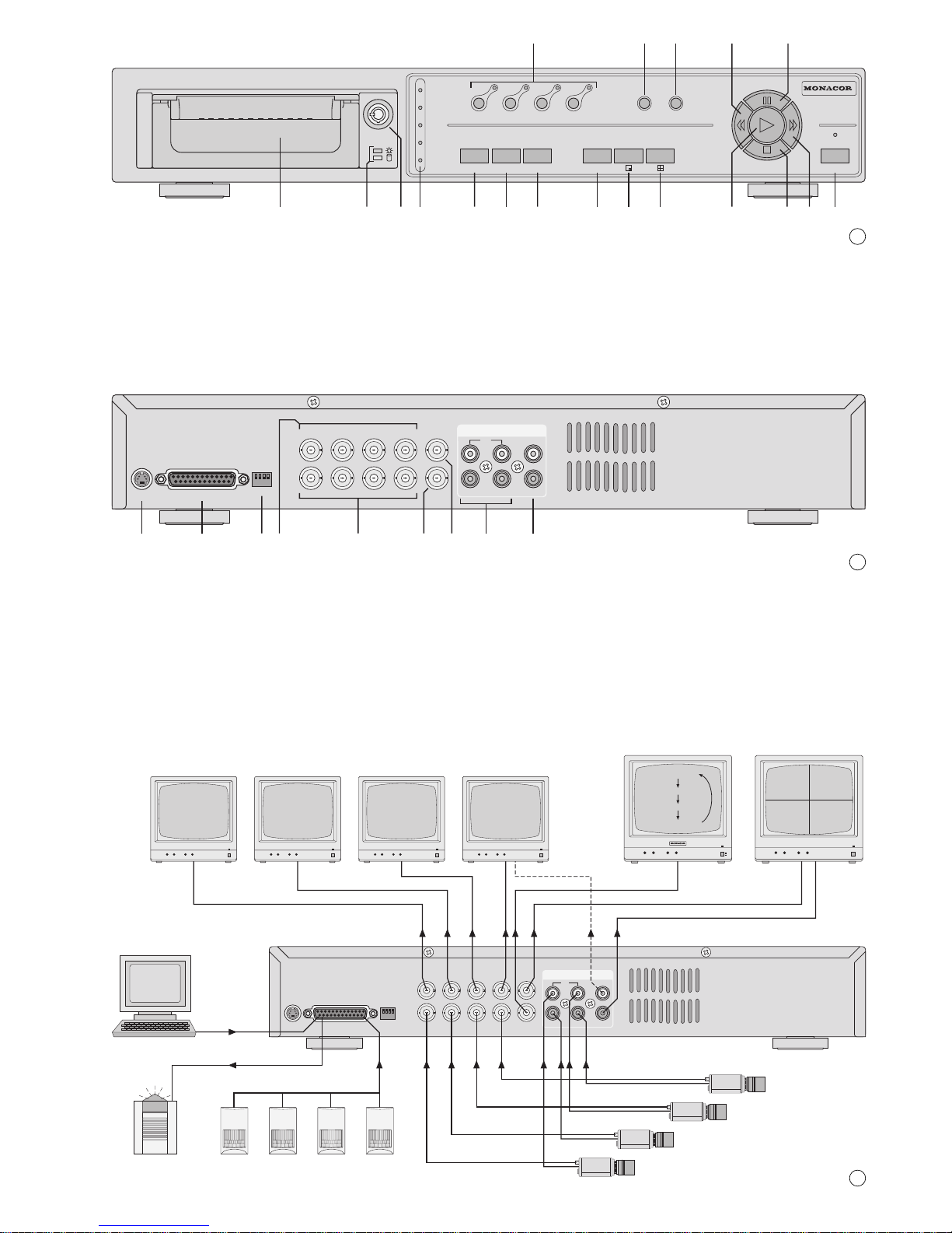
Bitte klappen Sie die Seite 3 heraus. Sie sehen
dann immer die beschriebenen Bedienelemente
und Anschlüsse.
1 Übersicht der Bedienelemente und
Anschlüsse
1.1 Frontseite (Abb. 1)
1 Zifferntasten „1“ bis „4“ zur Wahl eines Kamera-
kanals für die Ansicht im Vollbild-Format
2 Taste SLOW zum Reduzieren der Wiedergabe-
geschwindigkeit
3 Taste REC zum manuellen Starten einer Auf-
nahme
4 Taste REW/Left: dient
a für den schnellen und langsamen Bild-Rück-
lauf im Wiedergabebetrieb
b als Cursor-Taste „Links“ für Einstellungen im
Bildschirm-Menü
5 Taste PAUSE/Up: dient
a als Pausentaste im Wiedergabebetrieb
b als Cursor-Taste „Aufwärts“ für Einstellungen
im Bildschirm-Menü
6 auswechselbarer Festplatteneinschub
ZumHerausnehmen des Einschubs muss dieser
über das Schloss (8) entriegelt werden (siehe
Abb. 7 in Kapitel 12.1).
7 Kontroll-Anzeigen für den Festplatteneinschub:
grüne LED: Betriebsanzeige; leuchtet bei Strom-
versorgung der Festplatte
gelbe LED: leuchtet bei Zugriff auf die Festplatte
8 Schloss zum Verriegeln /Entriegeln des Festpla-
teneinschubs (6) mit den zwei beiliegenden
Schlüsseln, siehe auch Abb. 7 in Kapitel 12.1
9 LED-Statusanzeigen
HDD Full: leuchtet, wenn die Speicherkapazität
der Festplatte erschöpft ist
ALARM: leuchtet, wenn die Funktion „externer
Alarm“ für einen oder mehrere Kamera-
kanäle aktiviert ist (siehe Kap. 9.4, Einstellung ALARM im Menü CAMERA)
TIMER: leuchtet bei eingeschalteter Timer-
Funktion (siehe Kap. 9.2, Einstellung
TIMER ENABLE im Menü TIMER)
PLAY: leuchtet während der Wiedergabe
REC: leuchtet während der Aufnahme
10 Taste MENU zum Aufrufen des Bildschirm-
Menüs; nach dem Drücken der Taste wird das
4-stellige Passwort abgefragt:
Wurde das ab Werk voreingestellte Passwort
„0000“ beibehalten, zur Bestätigung die Taste
ENTER (11) drücken.
Wurde ein neues Passwort eingestellt (siehe
Kap. 9.5), mit der Cursor-Taste Left (4)
oder Right (18) die vier Stellen anwählen
und mit der Cursor-Taste Up (5) oder Down
(17) die jeweiligen Zahlen einstellen. Die Ein-
gabe mit der Taste ENTER (11) bestätigen.
Im Bildschirm-Menü dient diese Taste zum Bestätigen der Einstellungen und Ausblenden eines
Menüs.
11 Taste ENTER zum Aktivieren einer angewählten
Menüzeile
12 Taste SEARCH zum Aufrufen des Suchmenüs
für die gezielte Suche einer Aufnahme
13 Taste ZOOM zum Aufrufen der Zoom-Funktion
Bei aufgerufener Zoom-Funktion kann durch
Drücken der Taste ZOOM zwischen verschiedenen Bildausschnitten gewechselt werden.
14 Taste zum Aufrufen des Bild-im-Bild-Formats
(Einblendung eines kleinen Bildes in ein Vollbild)
15 Taste zum Aufrufen des Vierfachbild-Formats
16 Taste zum Starten der Wiedergabe
17 Taste STOP/Down: dient
a als Stopptaste während der Aufnahme und
der Wiedergabe
b als Cursor-Taste „Abwärts“ für Einstellungen
im Bildschirm-Menü
c nach einer Alarmauslösung zum Ausschalten
des Alarms und Stoppen der Alarmaufnahme
18 Taste FF/Right: dient
a für den schnellen und langsamen Bild-Vorlauf
im Wiedergabebetrieb
b als Cursor-Taste „Rechts“ für Einstellungen im
Bildschirm-Menü
19 Ein- /Ausschalter POWER; mit Kontroll-LED zur
Anzeige des Betriebszustands:
rot: Standby-Betrieb; der Recorder ist an die
Stromversorgung angeschlossen, aber
noch ausgeschaltet
grün: der Recorder ist eingeschaltet und be-
triebsbereit
1.2 Rückseite (Abb. 2)
20 Stromversorgungsbuchse POWER für den An-
schluss des beiliegenden Netzgerätes
21 25-polige Sub-D-Buchse EXTERNAL I/O für
verschiedene Alarm- und Steuerverbindungen;
Details siehe Kap. 4.3
➃
Sub-D-Buchse (Ansicht der Buchsenseite)
Pin 1: Masse
Pin 2+3: nicht belegt
Pin 4: Alarm-Eingang 4
Pin 5: Alarm-Eingang 2
Pin 6–10: nicht belegt
Pin 11: RS-232-Schnittstelle: TX
Pin 12: RS-485-Schnittstelle: A
Pin 13: Alarmausgang: NO-Kontakt („nor-
mally open“) des Relais
Pin 14–16: nicht belegt
Pin 17: Alarm-Eingang 3
Pin 18: Alarm-Eingang 1
Pin 19–22: nicht belegt
113
25
14
Please unfold page 3. Then you can always see
the operating elements and connections described.
1 Operating Elements and Connections
1.1 Front panel (fig. 1)
1 Numerical keys “1” to “4” for selection of a
camera channel for display in full screen format
2 Key SLOW to reduce the replay speed
3 Key REC for manual start of a recording
4 Key REW/Left: serves
a for the fast and slow rewind of pictures in the
replay mode
b as a cursor key Left for settings in the on-
screen menu
5 Key PAUSE/Up: serves
a as a pause key in the replay mode
b as a cursor key Up for settings in the on-
screen menu
6 Replaceable hard disk insertion
To remove the insertion, it must be unlocked via
its lock (8) [see fig. 7 in chapter 12.1]
7 Indicating LEDs for the hard disk insertion:
green LED: operating indication; lights up in
case of power supply of the hard
disk
yellow LED: lights up during access to the hard
disk
8 Lock for locking/unlocking the hard disk insertion
(6) with the two supplied keys, also see fig. 7 in
chapter 12.1
9 LED status indications
HDD Full: lights up if the storage capacity of
the hard disk is exhausted
ALARM: lights up if the function “external
alarm” has been activated for one or
several camera channels (see
chapter 9.4, setting ALARM in the
menu CAMERA)
TIMER: lights up with activated timer func-
tion (see chapter 9.2, setting TIMER
ENABLE in the menu TIMER)
PLAY: lights up during the replay
REC: lights up during the recording
10 Key MENU to call the on-screen menu; after
pressing the key, the 4-digit password is requested:
If the factory-set password “0000” has been
maintained, press the key ENTER (11) to confirm.
If a new password has been entered (see
chapter 9.5), select the four positions with the
cursor key Left (4) or Right (18) and set
the respective numbers with the cursor key Up
(5) or Down (17). Confirm the entry with the
key ENTER (11).
In the on-screen menu this key serves to confirm
the settings and to extinguish a menu.
11 Key ENTER to activate a selected line of the
menu
12 Key SEARCH to call the search menu for the
purposeful search of a recording
13 Key ZOOM to call the zoom function
With the zoom function called it is possible to
change between different picture cutouts by
pressing the key ZOOM
14 Key to call the picture-in-picture format (inser-
tion of a small picture into a full screen picture)
15 Key to call a quad format
16 Key to start the replay
17 Key STOP/Down: serves
a as a stop button during recording and replay
b as a cursor key Down for settings in the on-
screen menu
c after triggering an alarm to switch off the alarm
and to stop the alarm recording
18 Key FF/Right: serves
a for the fast and slow forward of the picture in
the replay mode
b as a cursor key Right for settings in the on-
screen menu
19 POWER switch; with indicating LED to display
the operating mode:
red: standby operation; the recorder is con-
nected to the power supply, but still
switched off
green:the recorder is switched on and ready for
operation
1.2 Rear panel (fig. 2)
20 POWER supply jack for connection of the sup-
plied power supply unit
21 25-pole Sub-D jack EXTERNAL I/O for different
alarm and control connections; details see chapter 4.3
➃
Sub-D jack (view of the jack side)
pin 1: ground
pins 2+3: not connected
pin 4: alarm input 4
pin 5: alarm input 2
pins 6–10: not connected
pin 11: RS-232 interface: TX
pin 12: RS-485 interface: A
pin 13: alarm output: NO contact (“nor-
mally open”) of the relay
pins 14–16: not connected
pin 17: alarm input 3
pin 18: alarm input 1
pins 19–22: not connected
113
25
14
5
GB
D
A
CH
Page 6

Pin 23: RS-232-Schnittstelle: RX
Pin 24: RS-485-Schnittstelle: B
Pin 25: Alarmausgang: gemeinsamer An-
schluss (COM) des Relais
22 Impedanzumschalter für die vier Videoeingänge
INPUT (24)
HI: Der jeweilige Videoeingang ist hoch-
ohmig; erforderlich, wenn ein weiteres
Gerät am darüber liegenden Videoausgang LOOP (23) angeschlossen ist
75Ω: Der jeweilige Videoeingang ist mit 75 Ω
abgeschlossen; erforderlich, wenn kein
Gerät am darüber liegenden Videoausgang angeschlossen ist
23 BNC-Ausgangsbuchsen LOOP 1 –4 zum Her-
ausführen der durchgeschleiften Signale der Kamera-Eingangsbuchsen (24)
24 BNC-Eingangsbuchsen INPUT 1–4 zum An-
schluss an die Videoausgänge der Kameras
25 BNC-Ausgangsbuchse CALL zum Anschluss an
den Videoeingang eines Nebenmonitors; der
Nebenmonitor zeigt die Kamerabilder im VollbildFormat mit automatischer Bildweiterschaltung
26 BNC-Ausgangsbuchse MAIN zum Anschluss an
den Videoeingang des Hauptmonitors; über den
Hauptmonitor können die Kamerabilder im Liveund im Wiedergabebetrieb in verschiedenen
Bildformaten angezeigt (siehe Kap. 6.1) und das
Bildschirm-Menü eingeblendet werden
27 Audioeingänge 1 – 4 (Cinch-Buchsen) zum An-
schluss an 4 Audioquellen (z.B. Audioausgänge
der verwendeten Kameras oder Mikrofonvorverstärker von separat aufgestellten Mikrofonen)
Hinweis: Es kann nur eine der vier Audioquellen
aufgezeichnet werden; den Audiokanal im Menü
SYSTEM (Kap. 9.5) auswählen.
28 Audioausgänge (Cinch-Buchsen) zum Anschluss
an den Audioeingang eines Monitors oder an
einen Line-Pegel-Eingang einer Audioanlage; an
beiden Ausgängen liegt das Signal des für die
Aufnahme ausgewählten Audiokanals an
2 Hinweise für den sicheren Gebrauch
Der Recorder und sein Netzgerät entsprechen der
EMV-Richtlinie für elektromagnetische Verträglichkeit 89/336/EWG. Das Netzgerät entspricht zusätzlich der Niederspannungsrichtlinie 73/23/EWG.
Beachten Sie auch unbedingt folgende Punkte:
●
Der Recorder und das Netzgerät sind nur zur Verwendung im Innenbereich geeignet. Schützen Sie
die Geräte vor Tropf- und Spritzwasser, hoher
Luftfeuchtigkeit und Hitze (zulässiger Einsatztemperaturbereich 10–40°C).
●
Stellen Sie keine mit Flüssigkeit gefüllten Gefäße,
z.B. Trinkgläser oder Vasen, auf die Geräte.
●
Die im Recorder entstehende Wärme muss durch
Luftzirkulation abgegeben werden. Darum dürfen
die Lüftungsschlitze am Gehäuse nicht abgedeckt
werden.
●
Stecken Sie nichts durch die Lüftungsschlitze!
Dies kann zu einem Defekt des Gerätes führen.
●
Nehmen Sie den Recorder nicht in Betrieb bzw.
ziehen Sie den Netzstecker des Netzgerätes
sofort aus der Steckdose, wenn:
1. sichtbare Schäden am Netzgerät, an dessen
Netzleitung oder am Recorder vorhanden sind,
2. nach einem Sturz oder Ähnlichem der Verdacht
auf einen Defekt besteht,
3. Funktionsstörungen auftreten.
Lassen Sie die Geräte in jedem Fall in einer Fachwerkstatt reparieren.
●
Ziehen Sie den Netzstecker des Netzgerätes nie
an der Zuleitung aus der Steckdose, fassen Sie
immer am Stecker an.
●
Verwenden Sie zum Reinigen nur ein trockenes
weiches Tuch, niemals Chemikalien oder Wasser.
●
Wird der Recorder oder das Netzgerät zweckentfremdet, falsch angeschlossen bzw. bedient oder
nicht fachgerecht repariert, kann keine Haftung für
daraus resultierende Sach- oder Personenschäden und keine Garantie für das Gerät übernommen werden.
●
Sollen der Recorder und das Netzgerät endgültig
aus dem Betrieb genommen werden, übergeben
Sie die Geräte zur umweltfreundlichen Entsorgung einem örtlichen Recyclingbetrieb.
3 Anwendungsmöglichkeiten
Der DMR-408A ist ein digitaler 4-Kanal-Multiplexrecorder und speziell für den Einsatz in Video-Überwachungsanlagen konzipiert. Er ist eine Kombination aus einem Digital-Recorder und einem
4-Kanal-Multiplexer. Die integrierte 80-GB-Festplatte reicht für Aufnahmen von bis zu ca. 1350
Stunden. Bei eingeschaltetem Überschreibmodus
ist ein Endlosbetrieb möglich.
Der Recorder bietet u.a. folgende Funktionen:
– Aufzeichnung von 4 Kameras
– 6 Aufnahmegeschwindigkeiten: 1–18 Bilder/Sek.
– Audioaufzeichnung für einen Kanal
– 4 Aufnahmequalitäten: Best, High, Normal, Basic
– 4Aufnahmemodi: manuelle, timergesteuerte,
durch ein Alarmsignal oder durch den Bewegungsdetektor ausgelöste Aufzeichnung
– Bewegungsdetektor für jeden Kamerakanal
unterschiedlich aktivierbar
– schnelle Suche einer Aufnahme über Zeitangabe
– Live-Überwachung in verschiedenen Anzeigefor-
maten ohne Beeinflussung einer Aufnahme
– Passwortschutz und Bediensperre
– Ereignisse während einer Aufnahme, wie z. B.
Bildverlust oder Stromunterbrechung, werden in
einer Liste protokolliert
– 4 Alarmeingänge, 1 Alarmausgang
– RS-232- und RS-485-Schnittstelle zur Fernsteue-
rung des Gerätes über Computer oder Terminal
Achtung! Das Netzgerät wird mit lebensgefährlicher Netzspannung versorgt. Nehmen Sie deshalb nie selbst Eingriffe in diesem Gerät vor. Durch
unsachgemäßes Vorgehen besteht die Gefahr
eines elektrischen Schlages. Außerdem erlischt
beim Öffnen des Netzgeräts oder des Recorders
jeglicher Garantieanspruch.
pin 23: RS-232 interface: RX
pin 24: RS-485 interface: B
pin 25: alarm output: common connection
(COM) of the relay
22 Impedance selector switch for the four video
inputs INPUT (24)
HI: the respective video input is of high im-
pedance; required if another unit is connected to the video output LOOP (23)
located above
75Ω: the respective video input is terminated
with 75Ω; required if no unit is connected
to the video output located above
23 BNC output jacks LOOP 1 – 4 for routing out the
fed-through signals of the camera input jacks
(24)
24 BNC input jacks INPUT 1 – 4 for connection to
the video outputs of the cameras
25 BNC output jack CALL for connection to the
video input of an auxiliary monitor; the auxiliary
monitor shows the camera pictures in the full
screen format with automatic sequential switching of pictures
26 BNC output jack MAIN for connection to the
video input of the main monitor; via the main
monitor the camera pictures can be displayed
during the live mode and replay mode in different
picture formats (see chapter 6.1) and the onscreen menu can be inserted
27 Audio inputs 1 – 4 (phono jacks) for connection
to 4 audio sources (e. g. audio outputs of the
cameras used or microphone preamplifiers of
microphones placed separately)
Note: Only one of the four audio sources can be
recorded; select the audio channel in the menu
SYSTEM (chapter 9.5).
28 Audio outputs (phono jacks) for connection to the
audio input of a monitor or to a line level input of
an audio system; at both outputs the signal of the
audio channel selected for the recording is present.
2 Safety Notes
The recorder and its power supply unit correspond
to the directive 89/336/EEC for electromagnetic
compatibility. The power supply unit additionally corresponds to the low voltage directive 73/23/EEC.
It is essential to observe the following items:
●
The recorder and the power supply unit are suitable for indoor use only. Protect the units against
dripping water and splash water, high air humidity,
and heat (admissible ambient temperature range
0–40°C).
●
Do not place any vessels filled with liquid, e.g. a
drinking glass or a vase, on the units.
●
The heat being generated in the recorder has to
be removed via air circulation. Therefore, the air
vents at the housing must not be covered.
●
Do not insert or drop anything into the air vents!
This could lead to a defect of the unit.
●
Do not set the recorder into operation, and immediately disconnect the mains plug of the power
supply unit from the mains socket if
1. there is visible damage to the power supply
unit, to its mains cable, or to the recorder,
2. a defect might have occurred after a drop or
similar accident,
3. there are malfunctions.
The units must in any case be repaired by skilled
personnel.
●
Never pull the mains cable to disconnect the
mains plug of the power supply unit from the
mains socket, always seize the plug!
●
For cleaning only use a dry, soft cloth, by no
means chemicals or water.
●
If the recorder or the power supply unit is used for
purposes other than originally intended, if it is not
correctly connected or operated, or not repaired in
an expert way, there is no liability for any resulting
personal damage or material damage and no
guarantee claims for the unit will be accepted.
●
If the recorder and the power supply unit are to be
put out of operation definitively, take them to a
local recycling plant for disposal which is not
harmful to the environment.
●
Important for U.K. Customers!
The wires in the mains lead of the power supply
unit are coloured in accordance with the following
code:
green/yellow = earth
blue = neutral
brown = live
As the colours of the wires in the mains lead of this
appliance may not correspond with the coloured
markings identifying the terminals in your plug,
proceed as follows:
1. The wire which is coloured green and yellow
must be connected to the terminal in the plug
which is marked with the letter E or by the earth
symbol , or coloured green or green and
yellow.
2. The wire which is coloured blue must be connected to the terminal which is marked with the
letter N or coloured black.
3. The wire which is coloured brown must be connected to the terminal which is marked with the
letter L or coloured red.
Warning – This appliance must be earthed.
3 Applications
The DMR-408A is a digital 4-channel multiplex
recorder specially designed for applications in video
surveillance systems. It is a combination of a digital
recorder and a 4-channel multiplexer. The integrated 80GB hard disk is sufficient for recordings of up
to 1350 hours approx. With activated overwrite
mode, a continuous operation is possible.
Attention!The power supply unit is supplied with
hazardous mains voltage. Leave servicing to
skilled personnel only. Inexpert handling may
cause an electric shock hazard. Furthermore, any
guarantee claim will expire if the power supply unit
or the recorder has been opened.
6
GB
D
A
CH
Page 7

4 Geräte anschließen
Vor dem Anschließen von Geräten bzw. vor dem
Ändern bestehender Anschlüsse den DMR-408A
ausschalten.
Die Abbildung 3 zeigt die möglichen Anschlüsse, die
jedoch nicht alle genutzt werden müssen:
Die Video- und Audiosignale von vier Kameras werden auf den DMR-408A gegeben. Zusätzlich zum
Haupt- und Nebenmonitor sind vier weitere Monitore
zur Überwachung der einzelnen Kamerakanäle
angeschlossen. Über die 25-polige Sub-D-Buchse
wird der DMR-408Aper Computer ferngesteuert. An
die Alarmeingänge der Buchse sind 4 Alarmsensoren angeschlossen und der Alarmausgang ist mit
einem Alarmgeber verbunden.
4.1 Video- und Audio-Eingänge
An die BNC-Buchsen INPUT (24) die Videoausgänge der Kameras anschließen. Für jeden der Eingänge den zugehörigen Impedanzschalter (22) in
die entsprechende Position stellen:
HI wenn ein weiteres Gerät am darüber liegen-
den Videoausgang LOOP(23) angeschlossen
ist. Der jeweilige Videoeingang ist dann hochohmig.
75Ω wenn kein Gerät am darüber liegenden Video-
ausgang angeschlossen ist. Der entsprechende Videoeingang wird mit 75Ω abgeschlossen.
Zur Tonaufzeichnung verfügt der Recorder über vier
Cinch-Eingangsbuchsen AUDIO IN (27). An die Audioeingänge können z. B. die Audioausgänge von
Kameras mit integrierten Mikrofonen angeschlossen
werden oder die Vorverstärker von separat aufgestellten Mikrofonen. Im Bildschirm-Menü wird eingestellt, welcher der vier Audiokanäle aufgezeichnet
bzw. wiedergegeben werden soll (siehe Einstellung
AUDIO INPUT im Menü SYSTEM, Kap. 9.5).
4.2 Video- und Audio-Ausgänge
Den Videoeingang des (Haupt-)Monitors für die
Live-Überwachung in verschiedenen Anzeigeformaten an die Buchse MAIN (26) anschließen. Über diesen Monitor werden auch die Bildaufzeichnungen
wiedergegeben und das Bildschirm-Menü angezeigt.
Zum zusätzlichen Betrachten aller Kamerabilder
im Vollbild-Format mit Bildweiterschaltung lässt sich
ein zweiter Monitor an die Buchse CALL (25) anschließen. Nicht benutzte Kanäle werden bei der
Bildweiterschaltung übersprungen.
Sollen an weiteren Überwachungsplätzen Kamerabilder ständig im Vollbild-Format angezeigt werden, lassen sich an die Buchsen LOOP 1 bis 4 (23)
zusätzliche Monitore anschließen. Alternativ kann
an diese Buchsen auch ein Multiplexer für einen
weiteren Überwachungsplatz angeschlossen werden.
Für die Tonwiedergabe steht an den beiden
Cinch-Buchsen AUDIO OUT(28) das Signal des für
die Aufnahme ausgewählten Audiokanals zur Verfügung. Der T on kann über einen Monitor mit integriertem Lautsprecher oder über eine Audioanlage wiedergegeben werden. Die Ausgänge mit je einem
Audioeingang von max. zwei Monitoren bzw. mit
den Line-Eingängen der Audioanlage verbinden.
4.3 Alarm- und Steueranschlüsse
Über die 25-polige Sub-D-Buchse EXTERNAL I/O
(21) bietet das Gerät vier Alarmeingänge, einen
Alarmausgang sowie Schnittstellen zur Fernsteuerung über einen Computer bzw. ein Terminal. Für
den Anschluss liegt dem Recorder ein 25-poliger
Stecker bei.
➄
Sub-D-Buchse (Ansicht der Buchsenseite)
4.3.1 Alarmeingänge
Als Alarmsensoren können z.B. Bewegungssensoren oder Lichtschranken eingesetzt werden, die
mit einem 5-V-TTL-Ausgang, Schließer (NO) oder
Öffner (NC) ausgestattet sind. Die Sensoren jeweils
an Masse (Pin 1) und an die folgenden Kontakte
anschließen:
Sensor für Kanal 1 an Kontakt 18
Sensor für Kanal 2 an Kontakt 5
Sensor für Kanal 3 an Kontakt 17
Sensor für Kanal 4 an Kontakt 4
Die Polarität des TTL-Alarmsignals (High oder Low)
bzw. der Kontakttyp (NO oder NC) muss für jeden
Kanal separat im Bildschirm-Menü eingestellt werden (siehe Spalte ALARM im Menü CAMERA, Kap.
9.4). Vom Hersteller ist Alarmauslösung durch einen
Low-Pegel bzw. Schließer (NO) voreingestellt.
4.3.2 Alarmausgang
Als potentialfreier Alarmausgang steht ein Relais mit
Schließer (NO) zur Verfügung (Kontakte 13 und 25).
Das Relais erlaubt das Schalten von ohmschen
Lasten bei max. 12V /500mA. An den Alarmausgang kann z.B. ein akustischer oder optischer
Alarmgeber angeschlossen werden.
4.3.3 Anschluss eines Computers/Terminals
Über die RS-232- oder die RS-485-Schnittstelle
lässt sich der Recorder mit einem Computer oder
Terminal fernsteuern. Der DMR-408A ist dabei nur
Datenempfänger, kann also keine Daten wie
Rückmeldungen senden. Die Codierung der einzelnen Funktionen ist in Kapitel 11 angegeben.
1. Bei Verwendung der RS-232-Schnittstelle Pin 23
(RX) und Pin 1 (Masse) mit dem Computer/Terminal verbinden.
2. Bei Verwendung der symmetrischen RS-485Schnittstelle Pin 12 (A) und Pin 24 (B) mit dem
Computer/Terminal verbinden. Die Abschirmung
mit Masse (Pin 1) verbinden.
Tipp: Die Verwendung verdrillter Leitungen verrin-
gert Störeinstrahlungen.
113
25
14
The recorder offers e.g. the following functions:
– recording of 4 cameras
– 6 recording speeds: 1 – 18 pictures/sec.
– audio recording for one channel
– 4 recording qualities: Best, High, Normal, Basic
– 4 recording modes: manual, timer-controlled,
recording triggered by an alarm signal or by the
motion detector
– motion detector to be activated differently for
each camera channel
– fast search for a recording via time indication
– live surveillance in different display formats with-
out affecting a recording
– password protection and key lock
– incidents during a recording, e. g. video loss or
power interruption, are recorded in a list
– 4 alarm inputs, 1 alarm output
– RS-232 interface and RS-485 interface for re-
mote control of the unit via computer or terminal
4 Connecting the Units
Prior to connection of units or change of existing
connections switch off the DMR-408A.
Fig. 3 shows the possible connections, however, not
all of them have to be used:
The video and audio signals of four cameras are fed
to the DMR-408A. In addition to the main monitor
and auxiliary monitor, four further monitors are
connected for surveillance of the individual camera
channels. Via the 25-pole Sub-D jack the DMR-408A
is remote-controlled by a computer. 4 alarm sensors
are connected to the alarm inputs of the jack and the
alarm output is connected to an alarm device.
4.1 Video inputs and audio inputs
Connect the video outputs of the cameras to the
BNC jacks INPUT (24). For each of the inputs set
the respective impedance selector switch (22) to the
corresponding position:
HI if a further unit is connected to the video
output LOOP (23) located above. Then the
respective video input is of high impedance.
75Ω if no unit is connected to the video output
located above. The corresponding video
input is terminated with 75Ω.
For audio recording, the recorder has four phono
input jacks AUDIO IN (27). For example, the audio
outputs of cameras with integrated microphones or
the preamplifiers of microphones placed separately
can be connected to the audio inputs. Settings are
made in the on-screen menu which of the four audio
channels are to be recorded or replayed (see setting
AUDIO INPUT in the menu SYSTEM, chapter 9.5).
4.2 Video outputs and audio outputs
Connect the video input of the (main) monitor for live
surveillance in different display formats to the jack
MAIN (26). Via this monitor also the video recordings
are replayed and the on-screen menu is displayed.
For additional viewing of all camera pictures in
the full screen format with sequential switching of
pictures it is possible to connect a second monitor to
the jack CALL (25). During the sequential switching
of pictures channels which are not used are skipped.
For displaying camera pictures permanently in
the full screen format at further places of surveillance, it is possible to connect additional monitors to
the jacks LOOP 1 to 4 (23). Alternatively it is also
possible to connect a multiplexer for another place
of surveillance to these jacks.
For audio reproduction the signal of the audio
channel selected for the recording is available at
both phono jacks AUDIO OUT (28). The sound can
be reproduced via a monitor with integrated speaker
or via an audio system. Connect the outputs to one
audio input each of two monitors as a maximum or
to the line inputs of the audio system.
4.3 Alarm and control connections
Via the 25-pole Sub-D jack EXTERNAL I/O (21) the
unit offers four alarm inputs, an alarm output, and
interfaces for remote control via a computer or a ter-
minal. For connection, a 25-pole plug is supplied
with the recorder.
➄
Sub-D jack (view of the jack side)
4.3.1 Alarm inputs
As alarm sensors e.g. motion detectors or light barriers can be used which are equipped with a 5V TTL
output, closing contact (NO), or opening contact
(NC). Connect the sensors to ground (pin 1) and to
the following contacts in each case:
sensor for channel 1 to contact 18
sensor for channel 2 to contact 5
sensor for channel 3 to contact 17
sensor for channel 4 to contact 4
The polarity of the TTL alarm signal (high or low) or
the contact type (NO or NC) must be set in the onscreen menu separately for each channel (see
column ALARM in the menu CAMERA, chapter 9.4).
The alarm triggering is factory-set with a low level or
closing contact (NO).
4.3.2 Alarm output
A relay with closing contact (NO) is available as a
floating alarm output (contacts 13 and 25). The relay
allows switching of ohmic loads at max. 12 V /
500mA. For example, an acoustical or optical alarm
device can be connected to the alarm output.
4.3.3 Connection of a computer/terminal
The recorder can be remote-controlled with a computer or terminal via the RS-232 interface or the RS485 interface. The DMR-408A is only data receiver,
it is not capable of transmitting data like return messages. The coding of the individual functions is indicated in chapter 11.
1. When using the RS-232 interface, connect pin 23
(RX) and pin 1 (ground) to the computer/terminal.
113
25
14
7
GB
D
A
CH
Page 8

5 Inbetriebnahme
1) Das Gerät ist mit einer 80-GB-Festplatte ausgestattet. Um eine längere Aufnahmezeit zu erhalten, lässt sich eine größere Festplatte bis zu
1000GB einsetzen – siehe dazu Kapitel 12.
2) V or dem Einschalten überprüfen, ob der Festplatteneinschub (6) verriegelt ist – siehe Abb. 6. Nur
bei verriegeltem Einschub ist die Festplatte betriebsbereit.
➅
Schloss für den Festplatteneinschub
In Position Aist der Einschub verriegelt.
3) Nach dem Anschluss aller Geräte das beiliegende
Netzgerät mit der Buchse POWER (20) verbinden und das Netzgerät über das mitgelieferte
Netzkabel an eine Steckdose (100–240V~/
50– 60 Hz) anschließen. Beim Anschluss an die
Stromversorgung gibt der interne Alarmsummer
einen Signalton ab.
Nach dem Anschluss an die Stromversorgung
befindet sich das Gerät im Standby-Modus [LED
über dem Schalter POWER (19) leuchtet rot].
4) Den Recorder mit dem Schalter POWER (19)
einschalten. Die Initialisierung des Geräts startet:
Alle LEDs der LED-Reihe (9) und der Zifferntasten (1) leuchten kurz auf. Auf dem Bildschirm
des Hauptmonitors erscheint die Meldung HDD
DETECTING, gefolgt von MASTER HDD CONNECTED.
Erscheint jedoch die Meldung PLEASE INSERT HDD AND LOCK THE KEY, ist die Festplatte nicht richtig installiert oder der Einschub
nicht verriegelt.
5) Nach der Initialisierung ist der Recorder betriebsbereit. Dies wird durch grünes Leuchten der LED
über dem Schalter POWER signalisiert. Die
grüne Betriebsanzeige (7) für den Festplatteneinschub leuchtet.
In der LED-Reihe (9) leuchtet die Anzeige
TIMER, wenn die Timer-Funktion eingeschaltet
ist (siehe Kap. 9.2, Einstellung TIMER ENABLE
im Menü TIMER) und die Anzeige ALARM, wenn
die Funktion „externer Alarm“ für einen oder mehrere Kamerakanäle aktiviert ist (siehe Kap. 9.4,
Einstellung ALARM im Menü CAMERA).
6) Der Recorder muss über ein Bildschirm-Menü
auf die Bedürfnisse der jeweiligen Anwendung
programmiert werden. Um die Einstellungen vorzunehmen, siehe Kapitel 9.
7) Zum Ausschalten den Schalter POWER drücken.
Der interne Alarmsummer gibt dann einen Signalton ab und die LED über dem Schalter wechselt wieder auf Rot.
Ist die Überwachungsanlage längere Zeit
nicht in Betrieb, das Netzgerät vom Netz trennen,
weil sowohl der Recorder als auch das Netzgerät
einen geringen Strom verbrauchen, selbst wenn
der Recorder ausgeschaltet ist.
5.1 Bedientasten sperren
Die Bedientasten können gesperrt werden, um zu
verhindern, dass Unbefugte Einstellungen am Gerät
vornehmen.
1) Zum Sperren der Bedientasten die beiden Tasten
MENU (10) und ENTER (11) gleichzeitig drücken. Auf dem Bildschirm erscheint die Meldung
KEY LOCKED und erlischt dann wieder.
2) Zum Aufheben der Sperrung die Tasten MENU
und ENTER erneut gleichzeitig drücken. Nach
dem Drücken der Tasten wird das 4-stellige
Passwort abgefragt: Das Passwort eingeben
(siehe unter „Aufrufen des Bildschirm-Menüs“ am
Anfang des Kap. 9) und mit der Taste ENTER
bestätigen. Auf dem Bildschirm wird KEY UNLOCKED eingeblendet und erlischt dann wieder.
6 Live-Überwachung
Die Live-Überwachung der aktuellen Kamerabilder
ist über folgende Monitore möglich:
1. Über den Hauptmonitor an der Buchse MAIN
(26); für diesen Monitor lassen sich verschiedene
Anzeigeformate auswählen, siehe dazu Kap. 6.1.
2. Über einen an der Buchse CALL (25) angeschlossenen Nebenmonitor; dieser zeigt alle angeschlossenen Kamerakanäle nacheinander im
Vollbild-Format (Sequenzschaltung). Nicht benutzte Kanäle werden übersprungen. Im Bildschirm-Menü lässt sich die Bildverweilzeit einstellen (siehe Menüzeile DWELL TIME im Menü
SYSTEM, Kap. 9.5). Sie ist vom Hersteller auf
2 Sekunden voreingestellt.
3. Über an den Buchsen LOOP 1 bis 4 (23) angeschlossene Monitore; diese Monitore zeigen nur
das Vollbild des zugehörigen Kamerakanals.
6.1 Anzeigeformate wählen
Das für den Hauptmonitor an Buchse MAIN (26)
zuletzt gewählte Anzeigeformat wird gespeichert, so
dass nach dem Einschalten oder nach einer Stromunterbrechung wieder die zuletzt eingestellte Bildanordnung erscheint.
6.1.1 Vollbild-Format
In diesem Format erscheint das gewählte Kamerabild als Vollbild auf dem Monitor.
1) Die Zifferntaste (1) des gewünschten Kamerakanals drücken. Die LED der Taste leuchtet.
2) Zum Umschalten auf eine andere Kamera die
zugehörige Zifferntaste drücken.
6.1.2 Mehrfachbild-Formate
Soll nicht nur ein Kamerabild zur Zeit auf dem
Hauptmonitor betrachtet werden, lässt sich eines
der beiden Mehrfachbild-Formate wählen:
Taste (15) für alle vier Bilder
Der Bildschirm ist zur Darstellung aller Kamerakanälen in vier gleich große Sektoren unterteilt.
A
B
●
Zum Schutz der Festplatte das Gerät vor dem
Trennen von der Stromversorgung zuerst über
den Schalter POWER (19) ausschalten.
●
Das Gerät nicht in einem kurzen Zeitraum einund ausschalten. Zwischen dem Ein- und Ausschalten müssen mindestens 3Sek. liegen.
2. When using the balanced RS-485 interface, connect pin 12 (A) and pin 24 (B) to the computer/terminal. Connect the screening to ground (pin 1).
Note: If twisted lines are used, the interference will
be reduced.
5 Setting into Operation
1) The unit is equipped with an 80 GB hard disk. To
obtain a longer recording time, a larger hard disk
of up to 1000GB can be inserted – see chapter 12.
2) Prior to switching on, check if the hard disk insertion (6) is locked – see fig. 6. Only with the insertion locked the hard disk is ready for operation.
➅
Lock for the hard disk insertion
In position Athe insertion is locked
3) After connection of all units connect the supplied
power supply unit to the jack POWER (20) and
the power supply unit via the supplied mains
cable to a socket (100–240V~/50–60Hz).
When connecting it to the power supply, the internal alarm buzzer will sound.
After connection to the power supply, the unit
is in the standby mode [LED above the POWER
switch (19) shows red].
4) Switch on the recorder with the POWER switch
(19). The initializing of the unit starts:
All LEDs of the LED row (9) and the numerical
keys (1) light up shortly. The message HDD
DETECTING is displayed on the screen of the
main monitor, followed by MASTER HDD
CONNECTED.
However, if the message PLEASE INSERT
HDD AND LOCK THE KEYis displayed, the hard
disk is not correctly installed or the insertion is not
locked.
5) After initializing, the recorder is ready for operation. This is signalized by the LED above the
POWER switch showing green. The green power
LED (7) for the hard disk insertion lights up.
The LED TIMER will light up in the LED row
(9) if the timer function has been activated (see
chapter 9.2, setting TIMER ENABLE in the menu
TIMER) as well as the LED ALARM if the function
“external alarm” has been activated for one or
several camera channels (see chapter 9.4, setting ALARM in the menu CAMERA).
6) The recorder must be programmed via an onscreen menu to the requirements of the respective
application. To make the settings, see chapter 9.
7) To switch off, press the POWER switch. Then the
internal alarm buzzer will sound and the LED
above the switch shows red again.
If the surveillance system is not in operation
for a longer time, disconnect the power supply
unit from the mains because both the recorder
and the power supply unit have a low power consumption even if the recorder is switched off.
5.1 Locking of operational keys
The operational keys can be locked to prevent
unauthorized persons from making settings at the
unit.
1) To lock the operational keys, press both keys
MENU (10) and ENTER (11) at the same time.
The message KEY LOCKED is shortly displayed
on the screen.
2) To cancel the locking, press the keys MENU and
ENTER at the same time again. After pressing
the keys, the 4-digit password is requested: enter
the password (see “Calling the on-screen menu”
at the beginning of chapter 9) and confirm with
the key ENTER. KEY UNLOCKED is shortly displayed on the screen.
6 Live Surveillance
Live surveillance of the present camera pictures is
possible via the following monitors:
1. Via the main monitor connected to the jack MAIN
(26); it is possible to select different display formats for this monitor, see chapter 6.1.
2. Via an auxiliary monitor connected to the jack
CALL (25); this monitor successively shows all
connected camera channels in the full screen format (sequential switching). Channels which are
not used are skipped. The picture dwell time can
be set in the on-screen menu (see menu line
DWELL TIME in the menu SYSTEM, chap. 9.5).
It is factory-set to 2 seconds.
3. Via monitors connected to the jacks LOOP 1 to 4
(23); these monitors only show the full screen
picture of the corresponding camera channel.
6.1 Selecting display formats
The last display format selected for the main monitor
connected to the jack MAIN (26) is memorized so
that after switching-on or after a power interruption
the picture arrangement last set will be displayed
again.
6.1.1 Full screen format
In this format the selected camera picture is displayed as a full screen picture on the monitor.
1) Press the numerical key (1) of the desired
camera channel. The LED of the key lights up.
2) To switch to another camera, press the corresponding numerical key.
6.1.2 Multiple picture formats
For viewing more than one camera picture on the
main monitor at a time, it is possible to select one of
the two multiple picture formats:
Key (15) for all four pictures
The screen is subdivided to display all camera channels in four sectors of the same size.
A
B
●
To protect the hard disk, first switch off the unit
via the POWER switch (19) prior to disconnecting it from the power supply.
●
Do not switch on and off the unit within a short
interval. There must be at least 3 seconds between switching on and off.
8
GB
D
A
CH
Page 9

Taste (14) für das Bild-im-Bild-Format
Auf dem Bildschirm erscheint ein Kamerakanal im
Vollbild-Format und ein weiterer Kamerakanal als
eingeblendetes kleines Bild.
Zum Auswählen der Kamerakanäle für das Bild-
im-Bild-Format:
1) Die Taste ENTER (11) drücken. Die Nummer
bzw. die Bezeichnung des Kamerakanals für das
Vollbild blinkt.
2) Mit einer der Zifferntasten (1) den gewünschten
Kamerakanal auswählen.
3) Danach mit der Cursor-Taste Left (4) oder
Right (18) die Nummer bzw. die Bezeichnung
hinter dem Schrägstrich für das kleine Bild
anwählen und den Kamerakanal mit einer der
Zifferntasten auswählen.
4) Danach den Auswahlmodus durch Drücken der
Taste MENU (10) beenden.
6.1.3 Vergrößerung eines Bildausschnittes
(Zoom-Funktion)
1) Die Taste ZOOM (13) drücken. Für das Bild (entweder das Vollbild oder bei dem Vierfachbild das
Bild im ersten Sektor) ist dann die Zoom-Funktion aktiviert:
Ein Ausschnitt des Bildes wird vergrößert
(doppelte Breite x doppelte Höhe) auf dem Bildschirm gezeigt. Zusätzlich ist das Komplettbild
verkleinert eingeblendet.
2) Im verkleinerten Komplettbild ist der jeweilige
Bildausschnitt, der gerade vergrößert angezeigt
ist, durch einen Rahmen markiert. Mit der Taste
ZOOM kann ein anderer Bildausschnitt ausgewählt werden: Mit jedem Drücken der Taste wird
auf den nächsten Bildausschnitt gesprungen, der
dann vergrößert angezeigt wird.
3) Zum Ausschalten der Zoom-Funktion ein anderes Anzeigeformat (Vollbild, Bild-im-Bild oder
Vierfachbild) mit der entsprechenden Taste (1, 14
oder 15) anwählen.
7 Aufnahme
Der Recorder bietet vier Aufnahmemodi:
1. manuell gestartete Aufnahme
2. timergesteuerte Aufnahme
3. Alarmaufnahme (durch ein externes Alarmsignal
ausgelöste Aufnahme)
4. durch den internen Bewegungsdetektor ausgelöste Aufnahme
Während einer Aufnahme leuchtet immer die Aufnahmeanzeige REC in der LED-Reihe (9). Fällt die
Stromversorgung während einer Aufnahme aus,
wird das aufgenommene Bild auf der Festplatte
gespeichert und das Gerät schaltet bei Wiederherstellung der Stromversorgung in den vorherigen Aufnahmemodus zurück.
Im Bild für den Hauptmonitor sind während einer
Aufnahme folgende Informationen eingeblendet:
1. Uhrzeit und Datum (entsprechend der Einstellung
TIME DISPLAYim Menü SYSTEM, Kap. 9.5)
2. den Kennbuchstaben für den Aufnahmemodus:
A bei Alarmaufnahme
D bei Aufnahme, die durch den Bewegungs-
detektor gestartet wurde
M bei manueller Aufnahme
T bei timergesteuerter Aufnahme
3. das Aufnahmesymbol ●
4. bei eingeschalteter Überschreibfunktion:
OW (= „overwrite“);
bei ausgeschalteter Überschreibfunktion:
die verbleibende Speicherkapazität der Festplatte, z.B. „032GB“ bei 32 Gigabyte Restspeicherkapazität
(Zum Ein-/Ausschalten der Überschreibfunktion
siehe Menü RECORD, Kapitel 9.3.)
7.1 Manuelle Aufnahme
Zum Starten der Aufnahme die Taste REC (3) drücken. Zum Beenden der Aufnahme die Stopptaste
(17) drücken.
Für die manuelle Aufnahme gelten die Einstellungen der Menüzeilen REC IPS und REC QUALITY
des Menüs RECORD (siehe Kapitel 9.3).
7.2 Timergesteuerte Aufnahme
Ist die Timer-Funktion aktiviert [siehe Kap. 9.2; bei
eingeschalteter Funktion leuchtet in der LED-Reihe
(9) die Anzeige TIMER], startet und stoppt der Recorder automatisch zu den im Menü TIMER festgelegten Zeiten. Durch Drücken der Stopptaste (17)
kann eine Aufnahme auch vorzeitig beendet werden.
Die Aufnahmequalität und Aufnahmegeschwindigkeit lässt sich im Menü TIMER für jede Aufnahme
separat einstellen.
7.3 Alarmaufnahme
Ist die Alarmfunktion aktiviert [siehe Kap. 9.4, Menüpunkt ALARM; bei eingeschalteter Funktion leuchtet
in der LED-Reihe (9) die Anzeige ALARM] und empfängt der Recorder ein Alarmsignal an einem der
Alarmeingänge [Pins 4, 5, 17 und 18 der Sub-DBuchse EXTERNAL I/ O (21)], schaltet das Gerät
auf Alarmaufnahme.
1. Falls zum Zeitpunkt des Alarms keine Aufnahme
läuft, schaltet der Recorder automatisch auf Auf-
nahme. Für die Aufnahmegeschwindigkeit und
Aufnahmequalität gelten die Einstellungen der
Menüzeilen ALARM REC IPS und ALARM REC
QUALITY des Menüs RECORD (Kapitel 9.3).
Nach dem Ablauf der Alarmdauer (Voreinstellung = 10 Sek, veränderbar in der Zeile ALARM
DURATION im Menü SYSTEM, siehe Kapitel 9.5)
stoppt die Aufnahme und der Recorder kehrt in
seinen vorherigen Betriebsmodus zurück.
2. Tritt ein Alarm während einer manuellen oder
timergesteuerten Aufnahme auf, so hat die
Alarmaufnahme Priorität, d. h. die Aufnahmegeschwindigkeit und -qualität ändern sich entspre-
●
Das gewählte Anzeigeformat für den Hauptmonitor hat keinen Einfluss auf eine Aufnahme.
Es werden bei jeder Aufnahme immer die Kamerakanäle aufgezeichnet, die in der Spalte RECORD des Menüs CAMERA nicht auf OFF
geschaltet sind – siehe Kapitel 9.4.
Key (14) for the picture-in-picture format
On the screen one camera channel is displayed in
the full screen format and another camera channel
as an inserted small picture.
To select the camera channels for the picture-in-
picture format:
1) Press the key ENTER (11). The number or the
designation of the camera channel for the full
screen picture flashes.
2) Select the desired camera channel with one of
the numerical keys (1).
3) Then select the number or the designation
behind the slash for the small picture with the cursor key Left (4) or Right (18) and select the
camera channel with one of the numerical keys.
4) Then press the key MENU (10) to stop the selection mode.
6.1.3 Enlargement of a picture cutout
(zoom function)
1) Press the key ZOOM (13). Then the zoom function is activated for the picture (either the full
screen picture or – in case of a quad picture – the
picture in the first sector):
A cutout of the picture is displayed on the
screen in an enlarged way (double width x double
height). In addition, the complete picture is inserted in reduced size.
2) In the sized-reduced complete picture the respective picture cutout which is being displayed
as an enlarged picture at present is marked by a
frame. With the key ZOOM another picture cutout
can be selected: With each pressing of the key
the unit goes to the next picture cutout which will
then be displayed as an enlarged picture.
3) To switch off the zoom function, select another
display format (full screen picture, picture-in-picture, or quad picture) with the corresponding key
(1, 14, or 15).
7 Recording
The recorder offers four recording modes:
1. manual start of recording
2. timer-controlled recording
3. alarm recording (recording triggered by an external alarm signal)
4. recording triggered by the internal motion detector
During a recording always the recording indication
REC in the LED row (9) lights up. If the power supply fails during a recording, the recorded picture will
be memorized on the hard disk and the unit will
switch back to its previous recording mode after the
power supply has been restored.
The following information is inserted in the pic-
ture for the main monitor during a recording:
1. time and date (according to the setting TIME DISPLAYin the menu SYSTEM, chapter 9.5)
2. the identification letter for the recording mode:
A for alarm recording
D for recording triggered by the motion detector
M for manual recording
T for timer-controlled recording
3. the recording symbol ●
4. with activated overwrite function:
OW (= “overwrite”);
with deactivated overwrite function:
the remaining storage capacity of the hard disk,
e.g. “032GB” for a remaining storage capacity of
32 gigabytes
(For activating/ deactivating the overwrite function see menu RECORD, chapter 9.3.)
7.1 Manual recording
To start the recording, press the key REC (3). To
stop the recording, press the key STOP (17).
The settings of the menu lines REC IPS and REC
QUALITY of the menu RECORD apply to the
manual recording (see chapter 9.3).
7.2 Timer-controlled recording
If the timer function is activated [see chapter 9.2;
with activated function the LED TIMER in the LED
row (9) lights up], the recorder will automatically
start and stop at the times defined in the menu
TIMER. It is also possible to stop a recording at any
time by pressing the key STOP (17).
The recording quality and the recording speed
can be set in the menu TIMER separately for each
recording.
7.3 Alarm recording
If the alarm function is activated [see chapter 9.4,
menu item ALARM; with activated function the indication ALARM in the LED row (9) lights up] and if the
recorder receives an alarm signal at one of the
alarm inputs [pins 4, 5, 17, and 18 of the Sub-D jack
EXTERNAL I/0 (21)], the unit will switch to alarm
recording.
1. If no recording is made at the time of alarm, the
recorder will automatically switch to recording.
For the recording speed and recording quality the
settings of the menu lines ALARM REC IPS and
ALARM REC QUALITY of the menu RECORD
apply (chapter 9.3).
After the alarm duration has elapsed (presetting = 10 seconds, it can be changed in the line
ALARM DURATION in the menu SYSTEM, see
chapter 9.5), the recording will stop and the recorder will return to its previous operating mode.
2. If an alarm occurs during a manual or timer-controlled recording, the alarm recording takes priority, i.e. the recording speed and the recording
quality change according to the settings in the
menu lines ALARM REC IPS and ALARM REC
●
The selected display format for the main monitor
does not affect a recording. During each recording always the camera channels are registered
which are not set to OFF in the column RECORD
of the menu CAMERA – see chapter 9.4.
9
GB
D
A
CH
Page 10

chend den Einstellungen der Menüzeilen ALARM
REC IPS und ALARM REC QUALITY. Nach
Ablauf der Alarmdauer schaltet der Recorder in
den vorherigen Aufnahmemodus zurück.
3. Wird zum Zeitpunkt eines Alarms gerade eine
Aufzeichnung abgespielt, erfolgt keine Aufnahme.
Durch Drücken der Stopptaste (17) kann eine
Alarmaufnahme auch vorzeitig beendet werden.
Weitere Informationen zu den Vorgängen im Alarmfall sind im Kapitel 10.1 angegeben.
7.4 Aufnahmestart durch den Bewegungs-
detektor
Ist der Bewegungsdetektor aktiviert (siehe Kapitel
9.4.1) und im Menü RECORD die Funktion MOTION
TRIGGER RECORD auf ON gestellt (siehe Kapitel
9.3), schaltet das Gerät bei einer erkannten Bewe-
gung auf Alarmaufnahme.
1. Falls zum Zeitpunkt des Alarms keine Aufnahme
läuft, schaltet der Recorder automatisch auf Aufnahme. Für die Aufnahmegeschwindigkeit und
Aufnahmequalität gelten die Einstellungen der
Menüzeilen ALARM REC IPS und ALARM REC
QUALITY des Menüs RECORD (Kapitel 9.3).
Nach dem Ablauf der Alarmdauer stoppt die
Aufnahme und der Recorder kehrt in seinen vorherigen Betriebsmodus zurück.
2. Tritt ein Alarm während einer manuellen oder
timergesteuerten Aufnahme auf, so hat die
Alarmaufnahme Priorität, d. h. die Aufnahmegeschwindigkeit und -qualität ändern sich entsprechend den Einstellungen der Menüzeilen ALARM
REC IPS und ALARM REC QUALITY. Nach
Ablauf der Alarmdauer schaltet der Recorder in
den vorherigen Aufnahmemodus zurück.
3. Wird zum Zeitpunkt der erkannten Bewegung
gerade eine Aufzeichnung abgespielt, erfolgt
keine Aufnahme.
Durch Drücken der Stopptaste (17) kann die Aufnahme auch vorzeitig beendet werden. Weitere
Informationen zu den Vorgängen im Alarmfall sind
im Kapitel 10.3 angegeben.
8 Wiedergabe
1) Zur Wiedergabe der letzten Aufzeichnung die
Starttaste (16) drücken. (Zur Wiedergabe einer
anderen Aufzeichnung siehe Kapitel 8.4.) Die
Wiedergabe beginnt ab dem Startpunkt der Aufzeichnung. Auf dem Bildschirm erscheint das
Symbol und in der LED-Reihe (9) leuchtet die
Anzeige PLAY. Ist das Ende der Aufzeichnung
erreicht, wird END eingeblendet.
2) Während der Wiedergabe lässt sich:
a mit den Zifferntasten (1) ein bestimmtes Ka-
merabild als Vollbild anzeigen
b mit der Taste ZOOM (13) ein Vollbild ver-
größern (siehe auch Kapitel 6.1.3)
c mit der Taste (14) das Bild-im-Bild-Format
wählen (siehe auch Kapitel 6.1.2)
d mit der Taste (15) alle vier Kamerakanäle
anzeigen
3) Soll die Wiedergabe rückwärts ablaufen, während
der Wiedergabe die T aste (4) drücken. Auf dem
Bildschirm erscheint das Symbol . Zum Zurückschalten auf Vorlauf die Starttaste drücken.
4) Um auf Standbild zu schalten, die Pausentaste
(5) drücken. Auf dem Bildschirm erscheint das
Symbol . Zum Weiterlaufen der Wiedergabe die
Starttaste oder die Pausentaste drücken.
5) Zum Stoppen der Wiedergabe die Stopptaste
(17) drücken.
8.1 Schneller Vor-/Rücklauf
Während der Wiedergabe im Vor- oder Rücklauf kann
auf 2fache, 4fache, 8fache, 16fache oder 32fache
Wiedergabegeschwindigkeit geschaltet werden.
1) Mit der Taste (18) die Vorlaufgeschwindigkeit
erhöhen bzw. mit der Taste (4) die Rücklaufgeschwindigkeit: Mit jedem Druck der entsprechenden T aste wird die jeweils nächste Geschwindigkeit angewählt. Die gewählte Geschwindigkeit
wird auf dem Bildschirm angezeigt, z. B. „ x8“
bei 8facher Vorlaufgeschwindigkeit oder „ x2“
bei doppelter Rücklaufgeschwindigkeit.
2) Zum Zurückschalten vom schnellen Vorlauf auf
Wiedergabe in Normalgeschwindigkeit die Starttaste (16) drücken.
Zum Zurückschalten vom schnellen Rücklauf
auf Rücklauf in Normalgeschwindigkeit die Taste
so oft drücken, bis wieder auf dem Bild-
schirm angezeigt wird.
8.2 Langsamer Vor-/Rücklauf
Während der Wiedergabe im Vor- oder Rücklauf
kann auf
1
/
2fache,
1
/
4fache,
1
/
8fache,
1
/
16fache oder
1
/32fache Wiedergabegeschwindigkeit geschaltet
werden.
1) Während der Wiedergabe zuerst die Taste
SLOW (2) drücken.
2) Mit der Vorlauf-Taste (18) oder mit der Rücklauf-Taste (4) die Geschwindigkeit anwählen:
Mit jedem Druck der entsprechenden Taste wird
die jeweils nächste Geschwindigkeit angewählt.
Die gewählte Geschwindigkeit wird auf dem Bildschirm angezeigt, z.B. „ x1/8“ bei Reduzierung
der Vorlaufgeschwindigkeit auf
1
/8, oder „ x1/2“
bei halber Rücklaufgeschwindigkeit.
3) Zum Zurückschalten vom langsamen Vorlauf auf
Wiedergabe in Normalgeschwindigkeit die Starttaste (16) drücken.
Zum Zurückschalten vom langsamen Rücklauf auf Rücklauf in Normalgeschwindigkeit zuerst die Starttaste , dann einmal die Taste
drücken.
8.3 Schrittweise Wiedergabe von
Einzelbildern im Pausenmodus
1) Während der Wiedergabe den Recorder mit der
Pausentaste (5) auf Standbild schalten.
2) Mit der Vorlauf-Taste (18) und der Rücklauf-
Taste (4) können die Einzelbilder der Aufnahme Schritt für Schritt angezeigt werden:
Mit jedem Druck der Taste wird auf das
nächste Einzelbild geschaltet. Wird die Taste
gedrückt gehalten, laufen die Einzelbilder nacheinander durch.
QUALITY. After the alarm duration has elapsed,
the recorder switches back to its previous recording mode.
3. If a recording is being replayed at the time of an
alarm, no recording will be made.
It is also possible to stop an alarm recording at any
time by pressing the key STOP (17). Further
information on the proceedings in case of alarm is
given in chapter 10.1.
7.4 Recording start by the motion detector
If the motion detector is activated (see chapter
9.4.1) and the function MOTION TRIGGER REC-
ORD is set to ON in the menu RECORD (see chapter 9.3), the unit will switch to alarm recording in
case of a recognized movement.
1. If no recording is made at the time of the alarm,
the recorder will automatically switch to recording. For the recording speed and the recording
quality the settings of the menu lines ALARM
REC IPS and ALARM REC QUALITY of the
menu RECORD apply (chapter 9.3).
After the alarm duration has elapsed, the
recording stops and the recorder returns to its
previous operating mode.
2. If an alarm occurs during a manual or timer-controlled recording, the alarm recording takes priority, i.e. the recording speed and recording quality
change according to the settings of the menu
lines ALARM REC IPS and ALARM REC QUALITY. After the alarm duration has elapsed, the
recorder switches back to its previous recording
mode.
3. If a recording is being replayed at the time of the
recognized movement, no recording will be
made.
It is also possible to stop the recording at any time
by pressing the key STOP (17). Further information on the proceedings in case of alarm is given in
chapter 10.3.
8 Replay
1) To replay the last recording, press the start key
(16). (To replay another recording, see chap-
ter 8.4.) The replay starts from the starting point
of the recording. The symbol is displayed on
the screen and the LED PLAYin the LED row (9)
lights up. If the end of the recording is reached,
END is inserted.
2) During the replay it is possible
a to display a defined camera picture as a full
screen picture with the numerical keys (1)
b to enlarge a full screen picture with the key
ZOOM (13) [also see chapter 6.1.3]
c to select the picture-in-picture format with the
key (14) [also see chapter 6.1.2]
d to display all four camera channels with the
key (15)
3) For rewind replay, press the key (4) while
replaying. The symbol is displayed on the
screen. To switch back to forward replay, press
the start key .
4) To switch to still picture, press the pause key
(5). The symbol is displayed on the screen. To
continue the replay, press the start key or the
pause key .
5) To stop the replay, press the key STOP (17).
8.1 Fast forward/rewind
During the replay in forward or rewind the recorder
can be set to different replay speeds: double, 4-fold,
8-fold, 16-fold, or 32-fold.
1) The forward speed is increased with the key
(18) and the rewind speed with the key (4):
with each pressing of the corresponding key, the
next higher speed is selected in each case. The
selected speed is displayed on the screen, e. g.
“ x8” in case of 8-fold forward speed or “ x2” in
case of double rewind speed.
2) To switch back from fast forward to replay at normal speed, press the start button (16).
To switch back from fast rewind to rewind at
normal speed, press the key so many times
until is again displayed on the screen.
8.2 Slow forward/rewind
During the replay in forward or rewind the recorder
can be set to different replay speeds:
1
/
2,
1
/
4,
1
/
8,
1
/
16
, or
1
/
32
.
1) During the replay first press the key SLOW (2).
2) Select the speed with the forward key (18)
or the rewind key (4): with each pressing
of the corresponding key the next speed is selected in each case. The selected speed is displayed on the screen, e.g. “ x1/8” if the forward
speed is reduced to
1
/8, or “ x1/2” at half rewind
speed.
3) To switch back from slow rewind to replay at normal speed, press the start key (16).
To switch back from slow rewind to rewind at
normal speed, first press the start key , then
the key once.
8.3 Stepwise replay of individual pictures in
the pause mode
1) During the replay switch the recorder to still pic-
ture by pressing the pause key (5).
2) With the forward key (18) and the rewind key
(4) the individual pictures of the recording can
be displayed step by step:
With each pressing of the key the unit
switches to the next individual picture. If the key
is kept pressed, the individual pictures are successively run through.
With each pressing of the key , the unit
switches to the previous individual picture. If the
key is kept pressed, the individual pictures are
run through in rewind order.
10
GB
D
A
CH
Page 11
Mit jedem Druck der Taste wird auf das
vorherige Einzelbild geschaltet. Wird die Taste
gedrückt gehalten, laufen die Einzelbilder nacheinander rückwärts durch.
3) Zum Beenden der Einzelbildwiedergabe die Starttaste oder die Pausentaste drücken.
8.4 Bestimmte Aufnahme suchen und ab-
spielen
Anhand eines Suchmenüs kann aus allen Aufzeichnungen gezielt eine bestimmte Aufzeichnung ausgewählt und wiedergegeben werden.
1) Die Taste SEARCH (12) drücken. Auf dem Bildschirm erscheint das Suchmenü:
2) Mit den Cursor-Tasten Up (5) und Down (17) können die 5 Untermenüs des Suchmenüs angewählt und mit der Taste ENTER (11) aufgerufen
werden.
3) Zum Verlassen des Suchmenüs die Taste MENU
(10) drücken.
Hinweise:
a Während einer Aufnahme ist die Taste SEARCH
gesperrt.
b Sind noch keine Aufnahmen gemacht worden,
erscheint beim Aufrufen des Suchmenüs für ca.
10Sek. die Einblendung DISK EMPTY. Die Meldung kann durch Drücken der Taste STOP
(17) auch sofort ausgeblendet werden.
8.4.1 LAST RECORD
Wiedergabe der letzten Aufnahme
Wird LAST RECORD mit der Taste ENTER (11) aufgerufen, schaltet der Recorder auf Wiedergabe der
Aufzeichnung, die zuletzt vorgenommen wurde.
8.4.2 FULL LIST
Gesamtliste aller Aufnahmen
Wird FULL LIST mit der Taste ENTER (11) aufgerufen, erscheint auf dem Bildschirm eine Liste sämtlicher Aufnahmen, z. B.:
Die Aufzeichnungen sind nach dem Zeitpunkt des
Aufnahmestarts sortiert. Zusätzlich zur Datums- und
Zeitangabe ist jede Aufzeichnung mit einem Kennbuchstaben für den Aufnahmemodus versehen:
A: Alarmaufnahme
D: durch den Bewegungsdetektor gestartete Auf-
name
M: manuelle Aufnahme
T: timergesteuerte Aufnahme
Die Abkürzung M-HDD steht für Master Hard Disk
Drive = Hauptfestplattenlaufwerk.
1) Auf einer Menüseite werden max. 8 Aufzeichnun-
gen aufgelistet. Mit der Cursor-Taste Left (4)
lässt sich die Liste „zurückblättern“, um länger zu-
rückliegende Aufzeichnungen zu finden und mit
der Cursor-T aste Right (18) kann wieder auf die
jüngsten Aufzeichnungen „vorgeblättert“ werden.
2) Soll die Menüseite ohne Auswahl einer Auf-
nahme wieder verlassen werden, die Taste
MENU (10) drücken.
3) Zum Auswählen einer Aufzeichnung diese mit der
Cursor-Taste Up (5) oder Down (17) anwählen
und sie mit der Taste ENTER oder der Starttaste
(16) aufrufen: Die Wiedergabe beginnt ab
dem Startpunkt der ausgewählten Aufzeichnung
und läuft – wenn sie nicht vorzeitig mit der Taste
STOP (17) gestoppt wird – ununterbrochen
bis zum Endpunkt der letzten Aufzeichnung.
8.4.3 ALARM LIST
Liste aller Alarmaufnahmen
Um nur die Alarmaufnahmen aufzulisten, die Zeile
ALARM LIST anwählen und die Liste mit der Taste
ENTER (11) aufrufen:
Die Aufzeichnungen sind nach dem Zeitpunkt des
Aufnahmestarts sortiert. Zusätzlich zur Datums- und
Zeitangabe sind die Aufzeichnung mit dem Kennbuchstaben „A“ für „Alarmaufnahme“ versehen.
1) Die Auswahl einer Aufzeichnung erfolgt wie bei
der Gesamtliste mit den Cursor-Tasten Right
(18) und Left (4) zum Vor- und Rückblättern
sowie den Cursor-Tasten Up (5) und Down (17)
zum Anwählen der Aufzeichnung.
2) Nach der Auswahl die Wiedergabe mit der Start-
taste oder der Taste ENTER starten: Die Wiedergabe beginnt ab dem Startpunkt der ausgewählten Alarmaufzeichnung und läuft – wenn sie
nicht vorzeitig mit der Taste STOP (17) gestoppt wird – ununterbrochen bis zum Endpunkt
der letzten Aufzeichnung. Dabei werden nicht nur
die Alarmaufnahmen durchlaufen, sondern alle
Aufnahmen, die nach der ausgewählten Alarmaufnahme aufgezeichnet wurden.
8.4.4 MOTION LIST
Liste der detektorgestarteten Aufnahmen
Um nur die Aufnahmen aufzulisten, die durch den
Bewegungsdetektor gestartet wurden, im Suchmenü die Zeile MOTION LIST anwählen und die
Liste mit der Taste ENTER (11) aufrufen. Jede Aufzeichnung ist am Zeilenanfang mit einem „D“ für Detektor gekennzeichnet. Die weitere Auswahl erfolgt
wie bei der Liste aller Alarmaufnahmen (Kap. 8.4.3).
A 26-SEP-2003 23:05:58 M-HDD
A 26-SEP-2003 01:58:52 M-HDD
A 20-SEP-2003 04:59:32 M-HDD
A 13-SEP-2003 05:03:00 M-HDD
A 09-SEP-2003 22:36:29 M-HDD
A 01-SEP-2003 00:07:04 M-HDD
A 29-AUG-2003 02:43:02 M-HDD
A 22-AUG-2003 04:12:33 M-HDD
:PAGE UP :PAGE DOWN
D 26-SEP-2003 23:05:58 M-HDD
T 26-SEP-2003 08:00:00 M-HDD
M 26-SEP-2003 06:45:20 M-HDD
A 26-SEP-2003 01:58:52 M-HDD
T 25-SEP-2003 08:00:00 M-HDD
T 24-SEP-2003 08:00:00 M-HDD
D 23-SEP-2003 07:30:21 M-HDD
A 22-SEP-2003 17:01:38 M-HDD
:PAGE UP :PAGE DOWN
(SEARCH)
LAST RECORD
FULL LIST
ALARM LIST
MOTION LIST
TIME SEARCH
3) To stop the individual picture replay, either press
the start key or the pause key .
8.4 Searching and replaying a certain re-
cording
By means of the search menu it is possible to select
a certain recording from all recordings in a purposeful way and to replay it.
1) Press the key SEARCH (12). The search menu is
displayed:
2) With the cursor keys Up (5) and Down (17) the
5 submenus of the search menu can be selected
and called with the key ENTER (11).
3) To exit the search menu, press the key MENU
(10).
Notes:
a During a recording the key SEARCH is locked.
b If no recordings have been made yet, the mes-
sage DISK EMPTYis inserted for approx. 10 seconds when calling the search menu. It is also
possible to extinguish the message immediately
by pressing the key STOP (17).
8.4.1 LAST RECORD
Replay of the last recording
If LAST RECORD is called with the key ENTER (11),
the recorder switches to replay of the last recording.
8.4.2 FULL LIST
Total list of all recordings
If FULLLIST is called with the key ENTER (11), a list
of all recordings is displayed on the screen, e.g.:
The recordings are sorted according to the time of
the recording start. In addition to the time/date indication each recording is provided with an identification letter for the recording mode:
A: alarm recording
D: recording started by the motion detector
M: manual recording
T: timer-controlled recording
The abbreviation M-HDD stands for Master Hard
Disk Drive
1) 8 recordings as a maximum are listed on a menu
page. With the cursor key Left (4) it is possible
to go back in the list to find recordings made at an
earlier date, and with the cursor key Right (18)
it is possible to go forward to the latest recordings
again.
2) To exit the menu without selection of a recording,
press the key MENU (10).
3) To select a recording, use the cursor key Up (5)
or Down (17) and call it with the key ENTER or
the start key (16): the replay starts from the
starting point of the selected recording and is
continuously replayed to the end point of the last
recording – unless it is stopped before with the
key STOP (17).
8.4.3 ALARM LIST
List of all alarm recordings
To list the alarm recordings only, select the line
ALARM LISTand call the list with the key ENTER (11):
The recordings are sorted according to the time of
the recording start. In addition to the time/date indication each recording is provided with the identification letter “A” for alarm recording:
1) Like in the total list, the selection of a recording is
made with the cursor keys Right (18) and
Left (4) to go forward and backward and with the
cursor keys Up (5) and Down (17) to select the
recording.
2) After the selection, start the replay with the start
key or the key ENTER: the replay starts from
the starting point of the selected alarm recording
and is continuously replayed to the end point of
the last recording – unless it is stopped before
with the key STOP (17). Not only the alarm
recordings are run through but all recordings
registered after the selected alarm recording.
8.4.4 MOTION LIST
List of the recordings triggered by the
detector
To only list the recordings triggered by the motion
detector, select the line MOTION LISTin the search
menu and call the list with the key ENTER (11).
Each recording is marked with a “D” for detector at
the beginning of the line. The further selection is
made as described for the list of all alarm recordings
(chapter 8.4.3).
A 26-SEP-2003 23:05:58 M-HDD
A 26-SEP-2003 01:58:52 M-HDD
A 20-SEP-2003 04:59:32 M-HDD
A 13-SEP-2003 05:03:00 M-HDD
A 09-SEP-2003 22:36:29 M-HDD
A 01-SEP-2003 00:07:04 M-HDD
A 29-AUG-2003 02:43:02 M-HDD
A 22-AUG-2003 04:12:33 M-HDD
:PAGE UP :PAGE DOWN
D 26-SEP-2003 23:05:58 M-HDD
T 26-SEP-2003 08:00:00 M-HDD
M 26-SEP-2003 06:45:20 M-HDD
A 26-SEP-2003 01:58:52 M-HDD
T 25-SEP-2003 08:00:00 M-HDD
T 24-SEP-2003 08:00:00 M-HDD
D 23-SEP-2003 07:30:21 M-HDD
A 22-SEP-2003 17:01:38 M-HDD
:PAGE UP :PAGE DOWN
(SEARCH)
LAST RECORD
FULL LIST
ALARM LIST
MOTION LIST
TIME SEARCH
11
GB
D
A
CH
Page 12

8.4.5 TIME SEARCH
Aufnahmesuche über Zeit-/Datumsangabe
Eine Aufzeichnung kann über die Angabe von Aufnahmezeit und -datum gesucht und aufgerufen werden. Das Untermenü TIME SEARCH anwählen und
mit der Taste ENTER (11) aufrufen. Auf dem Bildschirm erscheint eine Eingabemaske für die Suche.
Voreingestellt sind das aktuelle Datum und die aktuelle Stundenzahl, z.B.:
[Soll die Menüseite ohne weitere Auswahl wieder
verlassen werden, die Taste MENU (10) drücken.]
1) In die Zeile PLAY TIME das Datum und die
Stunde der gesuchten Aufnahme eingeben.
Dazu mit der Cursor-Taste Left (4) oder
Right (18) die zu verändernden Stellen anwählen
und mit der Cursor-Taste Up (5) oder Down (17)
das gewünschte Datum und die Stunde einstellen.
2) Nach der Eingabe die Taste ENTER oder die
Starttaste (16) drücken. Der Recorder beginnt
die Wiedergabe mit der ersten Aufnahme, die zu
der eingegebenen Uhrzeit stattfand.
Beispiel: PLAYTIME: 2004-JAN-27 06
Bei dieser Eingabe wird die Festplatte nach einer
Aufnahme am 27. Januar 2004 zwischen 6:00
Uhr und 6:59 Uhr durchsucht.
Wenn eine Aufnahme vor 6 Uhr begann und
nicht vor 6 Uhr endete, startet die Wiedergabe
dieser Aufnahme ab dem Zeitpunkt 06:00:00.
Hatte die erste Aufnahme nach 6 Uhr ihren
Aufnahmestart um 06:45:00, startet die Wiedergabe dieser Aufnahme ab dem Zeitpunkt
06:45:00.
Ist keine Aufnahme zwischen 06:00 und 06:59
vorhanden, erscheint auf dem Bildschirm die
Meldung NOT FOUND. Dann mit der Taste
MENU zurück zur Eingabemaske springen und
eine andere Stundenzahl eingeben. Eventuell die
gesuchte Aufzeichnung auch über die Liste mit
allen Aufnahmen aufrufen (Kapitel 8.4.2).
3) Die Wiedergabe läuft ununterbrochen bis zum
Endpunkt der letzten Aufzeichnung. Zum vorzeitig Beenden der Wiedergabe die Taste STOP
(17) drücken.
9 Änderung der Betriebsparameter
über das Bildschirm-Menü
Um den Multiplexrecorder optimal an die Überwachungsanlage anzupassen, lassen sich viele Betriebsparameter über ein Bildschirm-Menü einstellen. Das Menü kann nur über den an der Buchse
MAIN (26) angeschlossenen Hauptmonitor aufgerufen werden.
Die Einstellungen bleiben nach dem Verlassen
des Menüs dauerhaft gespeichert, d. h. auch nach
Ausfall der Versorgungsspannung.
Hinweise:
a Im Aufnahme- bzw. Wiedergabebetrieb kann das
Bildschirm-Menü nicht aufgerufen werden.
b Wenn nach dem Aufruf des Menüs 1 Min. lang
keine Einstellungen mehr vorgenommen werden,
blendet sich das Menü aus.
Aufrufen des Bildschirm-Menüs
1) Die Taste MENU (10) drücken. Auf dem Bildschirm erscheint die Meldung „PASSWORD:
0000“.
2) Um in das Hauptmenü zu gelangen, muss zuerst
das 4-stellige Passwort eingegeben werden:
a Bei der ersten Inbetriebnahme bzw. wenn das
ab Werk voreingestellte Passwort „0000“ beibehalten wurde, zur Bestätigung des Passworts „0000“ die Taste ENTER (11) drücken.
b Bei einem anderen Passwort als „0000“ mit
der Cursor-T aste Left (4) oder Right (18)
die Stellen des Wortes anwählen und mit der
Cursor-Taste Up (5) oder Down (17) die jewei-
ligen Zahlen einstellen. Die Eingabe durch
Drücken der Taste ENTER bestätigen.
3) Bei einer falschen Eingabe des Passwortes
erscheint die Meldung PASSWORD ERROR auf
dem Monitor. Die Eingabe muss wiederholt werden.
9.1 Hauptmenü
Nach der korrekten Passworteingabe wird das
Hauptmenü angezeigt:
Das Hauptmenü hat 5 Untermenüs:
TIMER: Einstellungen zur Timer-Funktion
RECORD: Aufnahmeeinstellungen
CAMERA: Einstellungen für die einzelnen Kamera-
kanäle
SYSTEM: Allgemeine Systemeinstellungen
EVENT: Abruf der Ereignisliste
Mit den Cursor-T asten Up (5) und Down (17) können
die Untermenüs angewählt und durch Drücken der
Taste ENTER (11) aufgerufen werden. Zuerst sollten die Einstellungen im Untermenü SYSTEM vorgenommen werden (siehe Kapitel 9.5).
Die in dieser Bedienungsanleitung dargestellten
Menüs zeigen die Voreinstellungen des Herstellers.
Auf diese Voreinstellungen lässt sich der Recorder
über das Menü SYSTEM in der Zeile SYSTEM
RESET jederzeit zurückstellen.
Zum Verlassen des Hauptmenüs die Taste MENU
(10) drücken.
(MENU)
TIMER
RECORD
CAMERA
SYSTEM
EVENT
PLAY TIME:2004-JAN-27 06
8.4.5 TIME SEARCH
Search for a recording via the time/ date
indication
A recording can be searched and called via the indication of recording time and date. Select the submenu TIME SEARCH and call it with the key ENTER
(11). An input mask for the search is displayed on
the screen. The present date and the present number of hours are preset, e.g.:
[To exit the menu page without further selection,
press the key MENU (10).]
1) Enter the date and the hour of the recording
searched for in the line PLAYTIME. For this purpose select the positions to be changed with the
cursor key Left (4) or Right (18) and set the
desired date and the hour with the cursor key Up
(5) or Down (17).
2) After the input press the key ENTER or the start
key (16). The recorder starts the replay with
the first recording which took place at the time
entered.
Example: PLAYTIME: 2004-JAN-27 06
With this input the hard disk is searched for a
recording on January 27th, 2004 between 6:00
a.m. and 6:59 a.m..
If the recording started before 6 a.m. and did
not stop before 6 a.m., the replay of this recording will start at 06:00:00.
If the first recording after 6 a.m. started at
06:45:00, the replay of this recording will start at
06:45:00.
If no recording was made between 06:00 and
06:59, the message NOT FOUND is displayed on
the screen. Then return to the input mask with the
key MENU and enter a different time. If desired,
also call the recording searched for via the list of
all recordings (chapter 8.4.2).
3) The replay is continuously replayed until the end
point of the last recording. To stop the replay
before the end, press the key STOP (17).
9 Changing the Operating Parameters
via the On-screen Menu
To match the multiplex recorder to the surveillance
system in an optimum way, many operational parameters can be set via an on-screen menu. The
menu can only be called via the main monitor
connected to the jack MAIN (26).
The settings remain permanently memorized
after exiting the menu, i. e. also after failure of the
supply voltage.
Notes:
a In the recording mode or replay mode the on-
screen menu cannot be called.
b If no settings are made for one minute after call-
ing the menu, the menu will disappear.
Calling the on-screen menu
1) Press the key MENU (10). The message “PASSWORD:0000” is displayed on the screen.
2) To go to the main menu, first the 4-digit password
must be entered:
a For the first setting into operation or if the fac-
tory-set password “0000” has been maintained, press the key ENTER (11) to confirm the
password “0000”.
b In case of another password than “0000” se-
lect the positions of the word with the cursor
key Left (4) or Right (18) and set the
respective numbers with the cursor key Up (5)
or Down (17). Press the key ENTER to confirm
the entry.
3) In case of a wrong input of the password the
message PASSWORD ERROR is displayed on
the monitor. The input must be repeated.
9.1 Main menu
After entering the password, the main menu is displayed:
The main menu has 5 submenus:
TIMER: settings for the timer function
RECORD: recording settings
CAMERA: settings for the individual camera chan-
nels
SYSTEM: general system settings
EVENT: calling the event list
With the cursor keys Up (5) and Down (17) the sub-
menus can be selected and called by pressing the
key ENTER (11). The settings should first be made
in the submenu SYSTEM (see chapter 9.5).
The menus presented in these operating instructions show the presettings of the manufacturer. It is
possible to reset the recorder to these presettings
via the menu SYSTEM in the line SYSTEM RESET
at any time.
To exit the main menu, press the key MENU (10).
(MENU)
TIMER
RECORD
CAMERA
SYSTEM
EVENT
PLAY TIME:2004-JAN-27 06
12
GB
D
A
CH
Page 13

9.2 Menü TIMER
Auf dieser Menüseite werden Einstellungen für
timergesteuerte Aufnahmen vorgenommen. Bei
einer timergesteuerten Aufnahme wird der Tag, der
Start- und der Endzeitpunkt der Aufnahme festgelegt. Die Aufnahme startet und stoppt dann automatisch zur eingestellten Zeit.
Timergesteuerte Aufnahme programmieren
1) Die Taste ENTER (11) drücken. Die erste Zeile ist
aktiviert und zeigt folgende Angaben:
2) Mit der Cursor-Taste Up (5) oder Down (17) in der
Spalte DAY den Tag bzw. die Tage anwählen, an
denen die Aufnahme stattfinden soll. Gewählt
werden kann zwischen folgenden Einstellungen:
OFF = die Aufnahme ist deaktiviert
DAILY = täglich
MON = montags
TUE = dienstags
WED = mittwochs
THU = donnerstags
FRI = freitags
SAT = samstags
SUN = sonntags
MO-FR = von Montag bis Freitag
SA-SU = Samstag und Sonntag
SEP-30 = einstellbares Aufnahmedatum
Ist das Datum angewählt, die Taste ENTER erneut drücken: Die Monatsangabe ist jetzt aktiviert. Mit der Cursor-Taste Up oder Down den
gewünschten Monat wählen. Dann mit der Cursor-Taste Right (18) die Tagesangabe anwählen und mit der Cursor-T aste Up oder Down
den gewünschten Tag einstellen. Das Aufnahmedatum mit der Taste MENU bestätigen.
3) In der Spalte START den Startzeitpunkt der Aufnahme festlegen und in der Spalte END den Endzeitpunkt der Aufnahme:
Mit der Cursor-T aste Right zuerst die Stelle
für die Stundeneingabe anwählen und die Stunde mit der Cursor-T aste Up oder Down einstellen.
Dann mit der Cursor-Taste Right die Stelle für
die Minuteneingabe anwählen und die Minuten
mit der Cursor-Taste Up oder Down einstellen.
Hinweis zum Start- und Endzeitpunkt:
Wenn als Aufnahmetag in der Spalte DAY ein
bestimmtes Datum oder ein bestimmter Wochentag (MON, TUE, WED, THU, FRI, SA Toder SUN)
gewählt ist und die Aufnahme bis in den folgenden Tag laufen soll, muss diese in zwei Aufnahmen aufgeteilt werden. Die Start- und Endzeitpunkte der beiden Aufnahmen müssen dabei
jeweils im selben Tag liegen.
Beispiel: Soll eine Aufnahme immer sonntags um
11:30 Uhr starten und am jeweils darauf folgenden Montag um 00:20 Uhr enden, darf die
Aufnahme nicht für SUN von 11:30 bis 00:20
festgelegt werden, weil sie dann erst am
nächsten Sonntag in einer Woche um 00:20
endet. Sie muss stattdessen aufgeteilt werden: die erste Aufnahme für SUN mit Startpunkt 11:30 und Endpunkt 23:59 und die
zweite für MON von 00:00 bis 00:20.
4) Mit der Cursor-Taste Right die nächste Spalte
QUALITY anwählen und mit der Cursor-Taste Up
oder Down die gewünschte Aufnahmequalität
einstellen. Es kann gewählt werden zwischen
BEST (beste Qualität), HIGH, NORMAL und
BASIC (niedrigste Qualität).
Die Aufnahmequalität einer Aufnahme wird
über den Grad der Bildkompression bestimmt: Je
höher die Aufnahmequalität, desto geringer ist
die Bildkompression. Dementsprechend benötigen Aufnahmen mit einer höheren Aufnahmequalität mehr Speicherplatz (siehe auch Kap. 13.1).
5) Mit der Cursor-Taste Right die nächste Spalte
IPS (images per second = Bilder pro Sekunde)
anwählen und mit der Cursor-Taste Up oder
Down die gewünschte Aufnahmegeschwindigkeit
einstellen. Es kann gewählt werden zwischen
den Einstellungen 1, 2, 3, 6, 12 und 18A. Bei
Audioaufzeichnungen muss die Einstellung 18A
gewählt werden. Siehe auch Kapitel 13.1.
6) Sind alle Angaben in dieser Zeile durchgeführt,
zur Bestätigung die Taste MENU (10) drücken.
(Falls die Aufnahme durch die Einstellung OFF in
der Spalte DAY deaktiviert wurde, blenden sich
nach dem Bestätigen alle Einstellungen der Zeile
aus. Sie sind jedoch wieder zu sehen, wenn die
Zeile erneut über die Taste ENTER aktiviert wird.)
7) Für weitere timergesteuerte Aufnahmen die entsprechenden Einstellungen in den folgenden Zeilen wiederholen.
Um die Timer-Funktion nutzen zu können, muss
diese generell eingeschaltet werden:
TIMER ENABLE
Ein-/Ausschalten der Timer-Funktion
1) Mit der Cursor-Taste Up oder Down die Zeile
TIMER ENABLE anwählen.
2) Die Taste ENTER drücken.
3) Durch Drücken der Cursor-Taste Up oder Down
die Timer-Funktion einschalten (YES) oder ausschalten (NO).
4) Die Einstellung durch Drücken der Taste MENU
bestätigen.
5) Zum Verlassen der Menüseite die Taste MENU
drücken.
(TIMER)
DAY START END QUALITY IPS
OFF 00:00 00:00 BASIC 18A
_____ __:__ __:__ ______ _ _ _
_____ __:__ __:__ ______ _ _ _
_____ __:__ __:__ ______ _ _ _
_____ __:__ __:__ ______ _ _ _
_____ __:__ __:__ ______ _ _ _
_____ __:__ __:__ ______ _ _ _
TIMER ENABLE: NO
(TIMER)
DAY START END QUALITY IPS
_____ __:__ __:__ ______ __ _
_____ __:__ __:__ ______ _ _ _
_____ __:__ __:__ ______ _ _ _
_____ __:__ __:__ ______ _ _ _
_____ __:__ __:__ ______ _ _ _
_____ __:__ __:__ ______ _ _ _
_____ __:__ __:__ ______ _ _ _
TIMER ENABLE: NO
9.2 Menu TIMER
On this menu page settings are made for timer-controlled recordings. With a timer-controlled recording
the day, the starting point and the end point of the
recording is defined. Then the recording will start
and stop automatically at the defined time.
Programming a timer-controlled recording
1) Press the key ENTER (11). The first line is activated and shows the following indications:
2) With the cursor key Up (5) or Down (17) select in
the column DAYthe day or the days at which the
recording is to be made. It is possible to select
the following settings:
OFF (recording is deactivated)
DAILY (daily)
MON (= on Mondays)
TUE (= on Tuesdays)
WED (= on Wednesdays)
THU (= on Thursdays)
FRI (= on Fridays)
SAT (= on Saturdays)
SUN (= on Sundays)
MO-FR (= from Monday to Friday)
SA-SU (= Saturday and Sunday)
SEP-30 (recording date to be adjusted).
If the date has been selected, press the key
ENTER again: the indication of the month is
activated now. Select the desired month with the
cursor key Up or Down. Then select the indication of the day with the cursor key Right (18)
and set the desired day with the cursor key Up or
Down. Confirm the recording date with the key
MENU.
3) Define the time for starting the recording in the
column START and the time for stopping the
recording in the column END:
With the cursor key Right first select the
position for the input of the hour and set the hour
with the cursor key Up or Down. Then select the
position for the input of the minute with the cursor
key Right and set the minutes with the cursor
key Up or Down.
Note concerning the starting point and end
point:
If a certain date or a certain weekday (MON,
TUE, WED, THU, FRI, SAT, or SUN) has been
selected as a recording day in the column DAY
and the recording is to continue to the following
day, it must be divided into two recordings. The
times for starting and stopping both recordings
must respectively be on the same day.
Example: If a recording is to start always on Sun-
days at 11.30 a.m. and is to stop on the following Monday at 00:20 a.m., the recording must
not be defined for SUN from 11:30 a.m. to
00:20 a.m. because in this case it will not stop
until Sunday next week at 00:20 a.m. Instead it
must be subdivided: the first recording for SUN
with the starting point at 11:30 a.m. and end
point 23:59 and the second for MON from
00:00 a.m. to 00:20 a.m.
4) Select the next column QUALITY with the cursor
key Right and set the desired recording quality with the cursor key Up or Down. It is possible
to select BEST(best quality), HIGH, NORMAL, or
BASIC (lowest quality).
The recording quality of a recording is defined
by the rate of the picture compression: The higher the recording quality, the lower the picture
compression. Accordingly, recordings with a
higher recording quality require more storage
space (also see chapter 13.1).
5) Select the next column IPS (images per second)
with the cursor key Right and set the desired
recording speed with the cursor key Up or Down.
It is possible to select the settings 1, 2, 3, 6, 12,
or 18A. For audio recordings the setting 18A has
to be selected. Also see chapter 13.1.
6) If all indications in this line are made, press the
key MENU (10) to confirm. (If the recording has
been deactivated by the setting OFF in the
column DAY, all settings of the line will disappear
after confirmation. However, they can be viewed
again if the line is reactivated via the key
ENTER.)
7) For further timer-controlled recordings repeat the
corresponding settings in the following lines.
T o be able to use the timer function, it must generally
be activated:
TIMER ENABLE
Activating/deactivating the timer function
1) Select the line TIMER ENABLE with the cursor
key Up or Down.
2) Press the key ENTER.
3) Press the cursor key Up or Down to activate the
timer function (YES) or to deactivate it (NO).
4) Press the key MENU to confirm the setting.
5) To exit the menu page, press the key MENU.
(TIMER)
DAY START END QUALITY IPS
OFF 00:00 00:00 BASIC 18A
_____ __:__ __:__ ______ _ _ _
_____ __:__ __:__ ______ _ _ _
_____ __:__ __:__ ______ _ _ _
_____ __:__ __:__ ______ _ _ _
_____ __:__ __:__ ______ _ _ _
_____ __:__ __:__ ______ _ _ _
TIMER ENABLE: NO
(TIMER)
DAY START END QUALITY IPS
_____ __:__ __:__ ______ __ _
_____ __:__ __:__ ______ _ _ _
_____ __:__ __:__ ______ _ _ _
_____ __:__ __:__ ______ _ _ _
_____ __:__ __:__ ______ _ _ _
_____ __:__ __:__ ______ _ _ _
_____ __:__ __:__ ______ _ _ _
TIMER ENABLE: NO
13
GB
D
A
CH
Page 14

9.3 Menü RECORD
Auf dieser Menüseite werden die Aufnahmeparameter eingestellt, die für manuelle Aufnahmen, für
detektorgestartete Aufnahmen und für Alarmaufnahmen gelten. Außerdem kann in diesem Menü die
Überschreibfunktion eingeschaltet werden.
HDD OVERWRITE
Ein-/Ausschalten der Überschreibfunktion
1) Mit der Cursor-Taste Up (5) oder Down (17) die
Zeile HDD OVERWRITE anwählen.
2) Die Taste ENTER (11) drücken.
3) Durch Drücken der Cursor-Taste Up oder Down
die Option NO oder YES einstellen.
Wird YES eingestellt, überschreibt der Recorder die ältesten Aufnahmen ohne weitere
Warnung, sobald die Festplatte voll ist (EndlosAufzeichnung).
Bei der Einstellung NO stoppt der Recorder
die Aufnahme, wenn die Festplatte voll ist. Der
Alarmsummer ertönt dann kurz und es leuchtet
die Anzeige HDD Full in der LED-Reihe (9).
4) Die Einstellung durch Drücken der Taste MENU
(10) bestätigen.
REC IPS
Wahl der Aufnahmegeschwindigkeit für die manuelle Aufnahme
1) Mit der Cursor-Taste Up oder Down die Zeile
REC IPS anwählen (images per second = Bilder
pro Sekunde).
2) Die Taste ENTER drücken.
3) Mit der Cursor-Taste Up oder Down die Aufnahmegeschwindigkeit einstellen. Es kann gewählt
werden zwischen den Einstellungen 1, 2, 3, 6, 12
und 18A. Bei Audioaufzeichnungen muss die
Einstellung 18A gewählt werden. Siehe auch
Kapitel 13.1.
4) Die Einstellung durch Drücken der Taste MENU
bestätigen.
REC QUALITY
Wahl der Aufnahmequalität für die manuelle Aufnahme
1) Mit der Cursor-Taste Up oder Down die Zeile
REC QUALITY anwählen.
2) Die Taste ENTER drücken.
3) Mit der Cursor-Taste Up oder Down die Aufnahmequalität auswählen. Es kann gewählt werden
zwischen BEST (beste Qualität), HIGH, NORMAL und BASIC (niedrigste Qualität).
Die Aufnahmequalität einer Aufnahme wird
über den Grad der Bildkompression bestimmt: Je
höher die Aufnahmequalität, desto geringer ist
die Bildkompression. Dementsprechend benötigen Aufnahmen mit einer höheren Aufnahmequalität mehr Speicherplatz. Siehe auch Kapitel 13.1.
4) Die Einstellung durch Drücken der Taste MENU
bestätigen.
Unter ALARM REC IPS wird die Aufnahmege-
schwindigkeit und unter ALARM REC QUALITY die
Aufnahmequalität für Alarmaufnahmen und für
detektorgestartete Aufnahmen eingestellt. Für diese
Aufnahmen sollten Aufnahmegeschwindigkeit und
Aufnahmequalität möglichst hoch gewählt werden.
Die Einstellungen erfolgen wie unter REC IPS und
REC QUALITY beschrieben.
MOTION TRIGGER RECORD
Ein-/Ausschalten des Aufnahmestarts durch den
Bewegungsdetekor
1) Mit der Cursor-Taste Up oder Down die Zeile
MOTION TRIGGER RECORD anwählen.
2) Die Taste ENTER drücken.
3) Durch Drücken der Cursor-Taste Up oder Down
die Option NO oder YES einstellen.
Wird YES eingestellt, startet der Detektor bei
einer erkannten Bewegung die Aufnahme. Zusätzlich muss jedoch für mindestens einen Kamerakanal der Detektor aktiviert werden (siehe Kap.
9.4.1). Bei der Einstellung NO erfolgt auch bei
aktiviertem Bewegungsdetektor keine Aufnahme.
4) Die Einstellung durch Drücken der Taste MENU
bestätigen.
Zum Verlassen der Menüseite die Taste MENU
drücken.
9.4 Menü CAMERA
Auf dieser Menüseite werden alle Einstellungen vorgenommen, die für jeden Kamerakanal separat
möglich sind.
Kamerakanal anwählen
1) Mit der Cursor-Taste Up (5) oder Down (17) die
Zeile für den gewünschten Kamerakanal anwählen. Im Hintergrund erscheint immer das
zugehörige Kamerabild.
2) Mit der Taste ENTER (11) die Zeile aktivieren. In
der Spalte TITLE blinkt das erste Zeichen.
3) Wenn alle Einstellungen nach folgender Beschreibung ausgeführt wurden, die Einstellungen
für den Kanals mit der Taste MENU (10) bestätigen. Danach kann ein anderer Kamerakanal angewählt oder mit der Taste MENU auf das Hauptmenü zurückgesprungen werden.
TITLE
Kamerabezeichnung
Für die Kamerabezeichnung können bis zu sechs
Zeichen verwendet werden. Voreingestellt ist jeweils
die entsprechende Kanalnummer 1–4. Folgende
Zeichen stehen zur Auswahl:
0–9, A–Z, -, :, ), ( und _ als Leerzeichen.
TITLE DWELL ALARM RECORD
---1--
ON 5 5 5 LOW EVENT
---2--
ON 5 5 5 LOW EVENT
---3--
ON 5 5 5 LOW EVENT
---4--
ON 5 5 5 LOW EVENT
(RECORD)
HDD OVERWRITE: NO
REC IPS: 18A
REC QUALITY: NORMAL
ALARM REC IPS: 18A
ALARM REC QUALITY: HIGH
MOTION TRIGGER RECORD: OFF
9.3 Menu RECORD
On this menu page the recording parameters are set
which apply to manual recordings, recordings triggered by detector, and alarm recordings. Furthermore, in this menu the overwrite function can be
activated.
HDD OVERWRITE
Activating/deactivating the overwrite function
1) Select the line HDD OVERWRITE with the cursor
key Up (5) or Down (17).
2) Press the key ENTER (17).
3) Press the cursor key Up or Down to set the option
NO or YES.
If YES is set, the recorder overwrites the
oldest recordings without any further warning as
soon as the hard disk is full (continuous recording).
If NO is set, the recorder stops the recording
when the hard disk is full. Then the alarm buzzer
shortly sounds and the LED HDD Full in the LED
row (9) lights up.
4) Press the key MENU (10) to confirm the setting.
REC IPS
Selecting the recording speed for the manual recording
1) Select the line REC IPS (images per second)
with the cursor key Up or Down.
2) Press the key ENTER.
3) Set the recording speed with the cursor key Up or
Down. It is possible to select the settings 1, 2, 3,
6, 12, or 18A. For audio recordings the setting
18A must be selected. Also see chapter 13.1.
4) Press the key MENU to confirm the setting.
REC QUALITY
Selecting the recording quality for the manual recording
1) Select the line REC QUALITYwith the cursor key
Up or Down.
2) Press the key ENTER.
3) Select the recording quality with the cursor key
Up or Down. It is possible to select BEST (best
quality), HIGH, NORMAL, or BASIC (lowest quality).
The recording quality of a recording is determined via the rate of the picture compression: the
higher the recording quality, the lower the picture
compression. Accordingly, recordings with a
higher recording quality require more storage
space. Also see chapter 13.1.
4) Press the key MENU to confirm the setting.
The recording speed is set under ALARM REC
IPS and the recording quality for alarm recordings
and for recordings triggered by detector under
ALARM REC QUALITY. For these recordings,
recording speed and recording quality should
be selected as high as possible. The settings are
made as described under REC IPS and REC QUALITY.
MOTION TRIGGER RECORD
Activating/deactivating the recording start by the
motion detector
1) Select the line MOTION TRIGGER RECORD
with the cursor key Up or Down.
2) Press the key ENTER.
3) Set the option NO or YES with the cursor key Up
or Down.
If YES is set, the detector starts the recording
with a recognized movement. In addition, the
detector must, however, be activated for at least
one camera channel (see chapter 9.4.1). With
the setting NO there is no recording even with
activated motion detector.
4) Press the key MENU to confirm the setting.
To exit the menu page, press the key MENU.
9.4 Menu CAMERA
On this menu page all settings are made which are
possible separately for each camera channel.
Selecting the camera channel
1) Select the line for the desired camera channel
with the cursor key Up (5) or Down (17). The corresponding camera picture is always displayed in
the background.
2) Activate the line with the key ENTER (11). The
first character flashes in the column TITLE.
3) If all settings have been made according to the
following description, confirm the settings for the
channel with the key MENU (10). Then it is possible to select another camera channel or to go
back to the main menu with the key MENU.
TITLE
Camera designation
Up to six characters can be used for the camera
designation. The corresponding channel number 1
to 4 is preset in each case. The following characters
can be selected:
0–9, A–Z, -, :, ), ( and _ as a blank.
TITLE DWELL ALARM RECORD
---1--
ON 5 5 5 LOW EVENT
---2--
ON 5 5 5 LOW EVENT
---3--
ON 5 5 5 LOW EVENT
---4--
ON 5 5 5 LOW EVENT
(RECORD)
HDD OVERWRITE: NO
REC IPS: 18A
REC QUALITY: NORMAL
ALARM REC IPS: 18A
ALARM REC QUALITY: HIGH
MOTION TRIGGER RECORD: OFF
14
GB
D
A
CH
Page 15

1) Mit der Cursor-Taste Left (4) oder Right
(18) die Schreibstelle anwählen, die verändert
werden soll. Nach der Aktivierung der Menüzeile
ist die erste Schreibstelle (blinkt) angewählt.
2) Mit der Taste Cursor-Taste Up oder Down das
gewünschte Zeichen auswählen.
3) Den V organg für alle weiteren Zeichen wiederholen.
DWELL
Kanal für einen an der Buchse CALL (25) angeschlossenen Monitor zeigen oder überspringen
Voreingestellt ist ON, wodurch der gewählte Kanal
auf dem an der Buchse CALL angeschlossenen
Monitor sequenziell gezeigt wird. Soll dieser Kanal
übersprungen werden, mit der Taste Right die
Spalte DWELL anwählen und mit der Taste Up oder
Down auf OFF stellen.
Einstellung von Helligkeit, Kontrast und Farbintensität
Zur optimalen Bildeinstellung lassen sich Helligkeit
, Kontrast und Farbintensität verändern. Mit
der Cursor-Taste Left oder Right die entsprechende Spalte anwählen. Der Wert lässt sich mit der
Taste Up oder Down zwischen 0 und 9 einstellen.
ALARM
Polarität des externen Alarmeingangs
Voreingestellt ist LOW, wodurch ein externer Alarm
an der Buchse EXTERNAL I/ O (21) durch einen
Schließer (NO) oder TTL-Low-Pegel ausgelöst wird.
Zum Ändern:
1) Mit der Cursor-Taste Left oder Right die
Spalte ALARM anwählen. LOW blinkt.
2) Mit der Taste Up oder Down die Einstellung HIGH
wählen, wenn der Alarm durch einen Öffner (NC)
oder TTL-High-Pegel (5V) ausgelöst werden
soll.
3) Soll keine Auslösung über den externen Alarm-
eingang erfolgen, die Einstellung OFF wählen.
RECORD
Aufnahmemodus
Voreingestellt ist EVENT, wodurch der Kanal bei
einem externen Alarm oder bei einer Alarmauslösung durch den Bewegungsdetektor häufiger aufgezeichnet wird. Im Normalaufnahmemodus ist die
Bildaufzeichnungsfolge: Kanal 1-2-3-4. Bei einem
Alarm im Kanal 1 und der Einstellung EVENT ist für
die Dauer der eingestellten Alarmzeit die Bildfolge
1-2-1-3-1-4-1.
1) Mit der Cursor-Taste Left oder Right die
Spalte RECORD anwählen. EVENT blinkt.
2) Soll bei einem Alarm der Kanal nicht häufiger aufgezeichnet werden, mit der Taste Up oder Down
die Einstellung NORMAL wählen.
3) Wenn der gewählte Kanal nicht aufgezeichnet
werden soll, die Einstellung OFF wählen.
9.4.1 Untermenü für den Bewegungsdetektor
Für jeden Kamerakanal lässt sich ein interner digitaler Bewegungsdetektor aktiveren. Bei einer erkannten Bewegung und bei der Voreinstellung EVENT in
der Spalte RECORD des Menüs CAMERA wird der
betroffene Kamerakanal für die Aufnahme und LiveÜberwachung häufiger abgetastet, z.B. 1-2-1-3-1-4-1
bei einer Bewegung im Kanal 1. Im zugehörigen LiveBild blinkt das Symbol für die Dauer der eingestellten Alarmzeit (Zeile ALARM DURATION im Menü
SYSTEM, Voreinstellung = 10s, siehe Kapitel 9.5).
Zusätzlich kann der Detektor den Signalsummer
aktivieren (Zeile MOTION AUDILBE ALARM im Menü
SYSTEM, Voreinstellung = OFF, siehe Kap. 9.5) und
eine Alarmaufnahme starten (Zeile MOTION TRIGGER RECORD im Menü RECORD, Voreinstellung =
OFF, siehe Kap. 9.3).
Menü für den Detektor einblenden
Dieses Menü ist ein Untermenü des Kameramenüs.
1) Im Kameramenü die Zeile für den gewünschten
Kamerakanal mit der Taste Up (5) oder Down
(17) anwählen. Im Hintergrund erscheint das
zugehörige Kamerabild.
2) Mit der Taste ENTER (11) die Zeile für den Kamerakanal aktivieren. In der Spalte TITLE blinkt
das erste Zeichen.
3) Die Taste ENTER erneut betätigen. Das Menü für
den Bewegungsdetektor erscheint:
Detektionsfeld einstellen
Das Detektionsfeld ist in 15 x 14 Segmente unterteilt.
Diese können einzeln, zeilenweise oder alle gleichzeitig aktiviert oder deaktiviert werden. In der Voreinstellung sind alle Segmente deaktiviert (Symbol ).
1) Nach dem Aufrufen des Menüs ist die 7. Zeile
angewählt und das 9. Segment von links blinkt.
Mit der Taste ENTER lässt sich dieses Segment
einschalten (Symbol ), mit der Taste ZOOM
(13) lassen sich alle Segmente einer Zeile einschalten und mit der Taste (14) alle Segmente
des Kamerabildes. Durch erneutes Betätigung
einer dieser Tasten werden die entsprechenden
Segmente wieder deaktiviert.
2) Zum Aktivieren anderer Segmente einer angewählten Zeile die Segmente einzeln mit der Cursor-Taste Left (4) oder (18) Right anwählen und die Taste ENTER drücken. Durch
erneutes Betätigen der Taste ENTER lässt sich
ein angewähltes Segment wieder deaktivieren.
3) Zum Anwählen einer anderen Zeile dienen die
Tasten Up und Down.
SENSITIVITY:032
1) Select the writing position to be changed with the
cursor key Left (4) or Right (18). After
activation of the menu line the first writing position (position will flash) is selected.
2) Select the desired character with the cursor key
Up or Down.
3) Repeat the procedure for all further characters.
DWELL
Displaying or skipping the channel for a monitor
connected to the jack CALL (25)
ON is preset by which the selected channel is displayed in a sequential way on the monitor connected
to the jack CALL. To skip this channel, select the
column DWELL with the key Right and set it to
OFF with the key Up or Down.
Setting of brightness, contrast, and colour intensity
For optimum picture setting it is possible to change
brightness , contrast , and colour intensity .
Select the corresponding column with the cursor key
Left or Right. The value can be set between 0
and 9 with the key Up or Down.
ALARM
Polarity of the external alarm input
LOW is preset by which an external alarm is trig-
gered at the jack EXTERNAL I / O (21) by a closing
contact (NO) or TTL low level. To change this:
1) Select the column ALARM with the cursor key
Left or Right. LOW flashes.
2) With the key Up or Down select the setting HIGH
if the alarm is to be triggered by an opening
contact (NC) or TTL high level (5V).
3) If no triggering is to be made via the external
alarm input, select the setting OFF.
RECORD
Recording mode
EVENT is preset by which the channel is more fre-
quently recorded in case of an external alarm or in
case of an alarm triggered by the motion detector.
The picture recording sequence in the standard
recording mode is: channels 1-2-3-4. With an alarm
in channel 1 and the setting EVENT the picture
sequence is 1-2-1-3-1-4-1 for the duration of the
alarm time set.
1) Select the column RECORD with the cursor key
Left or Right. EVENT flashes.
2) For not recording the channel more frequently in
case of alarm, select the setting NORMAL with
the key Up or Down.
3) For not recording the selected channel, select the
setting OFF.
9.4.1 Submenu for the motion detector
For each camera channel an internal digital motion
detector can be activated. With a recognized movement and the presetting EVENT in the column
RECORD of the menu CAMERA, the camera channel concerned is more frequently scanned for the
recording and live surveillance, e. g. 1-2-1-3-1-4-1
in case of a movement in channel 1. In the corresponding live picture the symbol flashes for the
duration of the alarm time set (line ALARM DURATION in the menu SYSTEM, presetting = 10s, see
chapter 9.5).
In addition, the detector can activate the alarm
buzzer (line MOTION AUDIBLE ALARM in the menu
SYSTEM, presetting = OFF, see chapter 9.5) and
start an alarm recording (line MOTION TRIGGER
RECORD in the menu RECORD, presetting = OFF,
see chapter 9.3).
Inserting the menu for the detector
This menu is a submenu of the camera menu.
1) Select the line for the desired camera channel in
the camera menu with the key Up (5) or Down
(17). The corresponding camera picture is dis-
played in the background.
2) Activate the line for the camera channel with the
key ENTER (11). The first character flashes in the
column TITLE.
3) Actuate the key ENTER again. The menu for the
motion detector is displayed:
Setting the detection field
The detection field is subdivided into 15 x 14 segments. They can be activated or deactivated individually, per line, or all at the same time. In the presetting all segments are deactivated (symbol ).
1) After calling the menu, the 7th line is selected
and the 9th segment from the left flashes. It is
possible to activate this segment (symbol ) with
the key ENTER, all segments of a line can be
activated with the key ZOOM (13) and all segments of the camera picture with the key (14).
Actuate one of these keys again to deactivate the
corresponding segments.
2) For activating other segments of a selected line,
select the segments individually with the cursor
key Left (4) or Right (18) and press the key
ENTER. Actuate the key ENTER again to deactivate a selected segment.
3) The keys Up and Down serve to select another
line.
SENSITIVITY:032
15
GB
D
A
CH
Page 16

Empfindlichkeit einstellen
Die Empfindlichkeit für das Auslösen eines Alarms
zwischen 000 (höchste Empfindlichkeit) und 255
(geringste Empfindlichkeit) mit den Tasten REC (3)
und SLOW (2) einstellen. Der voreingestellte Wert
beträgt 032.
Speichern und Menü verlassen
1) Die Taste MENU (10) drücken. Das Menü wird
ausgeblendet. Das Kameramenü erscheint wieder. Die Einstellungen sind gespeichert.
2) Die Taste MENU erneut betätigen, um die Menüzeile im Kameramenü zu deaktivieren.
3) Jetzt kann mit den Tasten Up oder Down ein
anderer Kamerakanal angewählt und durch anschließendes Drücken der Taste ENTER aktiviert
werden oder mit der Taste MENU auf das Hauptmenü zurückgesprungen werden.
9.5 Menü SYSTEM
Auf dieser Menüseite können folgende allgemeine
Systemeinstellungen vorgenommen werden:
AUDIO INPUT
Auswahl des Audioeingangs
1) Mit der Cursor-Taste Up (5) oder Down (17) die
Zeile AUDIO INPUT anwählen.
2) Die Taste ENTER (11) drücken.
3) Durch Drücken der Cursor-Taste Up oder Down
einen der vier Audiokanäle 1 – 4 auswählen. Nur
dieser Audiokanal wird aufgenommen bzw. wiedergegeben.
4) Die Einstellung durch Drücken der Taste MENU
(10) bestätigen.
INT AUDIBLE ALARM
Ein-/Ausschalten des internen Alarmsummers
1) Mit der Cursor-Taste Up oder Down die Zeile INT
AUDIBLE ALARM anwählen.
2) Die Taste ENTER drücken.
3) Durch Drücken der Cursor-Taste Up oder Down
die Option ON oder OFF einstellen.
Ist ON eingestellt, gibt der Alarmsummer
einen Alarmton ab, wenn das Videoeingangssignal von einer angeschlossenen Kamera unterbrochen wird oder wenn über die Buchse
EXTERNAL I/O (21) ein Alarm ausgelöst wird.
Wird OFF eingestellt, ist der Alarmsummer
ausgeschaltet.
4) Die Einstellung durch Drücken der Taste MENU
bestätigen.
Hinweis: Auch wenn der Summer ausgeschaltet ist,
ertönt ein kurzes akustisches Signal beim Anschluss
der Stromversorgung und nach dem Ausschalten.
Auch das Betätigen der Bedientasten wird immer
akustisch signalisiert.
EXT AUDIBLE ALARM
Alarm-Relais aktivieren/deaktivieren
1) Mit der Cursor-Taste Up oder Down die Zeile
EXTAUDIBLE ALARM anwählen.
2) Die Taste ENTER drücken.
3) Durch Drücken der Cursor-Taste Up oder Down
die Option ON oder OFF einstellen.
Ist ON eingestellt, schließt das interne Alarmrelais seinen Kontakt, wenn das Videoeingangssignal einer angeschlossenen Kamera unterbrochen wird oder wenn über die Buchse
EXTERNAL I/O (21) ein Alarm ausgelöst wird.
Wird OFF eingestellt, ist das Alarmrelais deaktiviert.
4) Die Einstellung durch Drücken der Taste MENU
bestätigen.
MOTION AUDIBLE ALARM
Alarmauslösung durch den Bewegungsdetektor ein-/
ausschalten
1) Mit der Cursor-Taste Up oder Down die Zeile
MOTION AUDIBLE ALARM anwählen.
2) Die Taste ENTER drücken.
3) Durch Drücken der Cursor-Taste Up oder Down
die Option ON oder OFF einstellen.
Einstellung ON: Erkennt der Detektor eine
Bewegung, ertönt der Alarmsummer (wenn der
Summer nicht in der Zeile INT AUDIBLE ALARM
ausgeschaltet wurde) und das interne Alarmrelais schließt (wenn es nicht in der Zeile EXT
AUDIBLE ALARM ausgeschaltet wurde). Zusätzlich muss jedoch für mindestens einen Kamerakanal der Detektor aktiviert werden (siehe Kapitel
9.4.1).
Ist OFF eingestellt, erfolgt keine Alarmauslösung durch den Bewegungsdetektor.
ALARM DURATION
Einstellen der Alarmdauer
1) Mit der Cursor-Taste Up oder Down die Zeile
ALARM DURATION anwählen.
2) Die Taste ENTER drücken.
3) Mit der Cursor-Taste Up oder Down die gewünschte Alarmdauer auswählen:
10SEC, 15SEC, 20SEC, 30SEC, 1MIN, 2MIN,
3MIN, 5MIN, 10MIN, 15MIN, 30MIN oder
ALWAYS (= Daueralarm).
4) Die Einstellung durch Drücken der Taste MENU
bestätigen.
(SYSTEM)
AUDIO INPUT: 1
INT AUDIBLE ALARM: ON
EXT AUDIBLE ALARM: ON
MOTION AUDIBLE ALARM: OFF
ALARM DURATION: 10 SEC
DWELL TIME: 02 SEC
MESSAGE LATCH: NO
TITLE DISPLAY: ON
TIME DISPLAY: Y/M/D
2004-JAN-30(FRI) 17:10:22
NEW PASSWORD: xxxx
CLEAR HDD: NO
SYSTEM RESET: NO
REMOTE MODE: RS-232
BAUD RATE: 9600
REMOTE ID: 000
Setting the sensitivity
Set the sensitivity for triggering an alarm between
000 (highest sensitivity) and 255 (lowest sensitivity)
with the keys REC (3) and SLOW (2). The preset
value is 032.
Memorizing and quitting the menu
1) Press the key MENU (10). The menu will disappear. The camera menu is displayed again. The
settings are memorized.
2) Press the key MENU again to deactivate the
menu line in the camera menu.
3) It is now possible to select another camera channel with the key Up or Down and to activate it by
subsequently pressing the key ENTER or to go
back to the main menu with the key MENU.
9.5 Menu SYSTEM
The following general system settings can be made
on this menu page:
AUDIO INPUT
Selecting the audio input
1) Select the line AUDIO INPUT with the cursor key
Up (5) or Down (17).
2) Press the key ENTER (11).
3) Press the cursor key Up or Down to select one of
the four audio channels 1 to 4. Only this audio
channel is recorded or replayed.
4) Press the key MENU (10) to confirm the setting.
INT AUDIBLE ALARM
Activating/deactivating the internal alarm buzzer
1) Select the line INT AUDIBLE ALARM with the
cursor key Up or Down.
2) Press the key ENTER.
3) Press the key Up or Down to set the option ON or
OFF.
If ON is set, the alarm buzzer emits an alarm
sound if the video input signal of a connected
camera is interrupted or if an alarm is triggered
via the jack EXTERNAL I/O (21).
If OFF is set, the alarm buzzer is switched off.
4) Press the key MENU to confirm the setting.
Note: Even if the buzzer is switched off, a short
acoustic signal sounds when connecting the power
supply and after switching-off. Also actuating the
operational keys will always be indicated by an
acoustical signal.
EXT AUDIBLE ALARM
Activating/deactivating the alarm relay
1) Select the line EXT AUDIBLE ALARM with the
cursor key Up or Down.
2) Press the key ENTER.
3) Press the cursor key Up or Down to set the option
ON or OFF.
If ON is set, the internal alarm relay closes its
contact if the video input signal of a connected
camera is interrupted or if an alarm is triggered
via the jack EXTERNAL I/O (21).
If OFF is set, the alarm relay is deactivated.
4) Press the key MENU to confirm the setting.
MOTION AUDIBLE ALARM
Activating/ deactivating the alarm triggering by the
motion detector
1) Select the line MOTION AUDIBLE ALARM with
the cursor key Up or Down.
2) Press the key ENTER.
3) Press the cursor key Up or Down to set the option
ON or OFF.
Setting ON: if the detector recognizes a movement, the alarm buzzer sounds (unless the buzzer has been switched off in the line INTAUDIBLE
ALARM) and the internal alarm relay closes
(unless it has been switched off in the line EXT
AUDIBLE ALARM). However, in addition the
detector has to be activated for at least one
camera channel (see chapter 9.4.1).
If OFF is set, no alarm will be triggered by the
motion detector.
ALARM DURATION
Setting the alarm duration
1) Select the line ALARM DURATION with the cursor key Up or Down.
2) Press the key ENTER.
3) Select the desired alarm duration with the cursor
key Up or Down:
10SEC, 15SEC, 20SEC, 30SEC, 1MIN, 2MIN,
3MIN, 5MIN, 10MIN, 15MIN, 30MIN, or
ALWAYS (= permanent alarm).
4) Press the key MENU to confirm the setting.
(SYSTEM)
AUDIO INPUT: 1
INT AUDIBLE ALARM: ON
EXT AUDIBLE ALARM: ON
MOTION AUDIBLE ALARM: OFF
ALARM DURATION: 10 SEC
DWELL TIME: 02 SEC
MESSAGE LATCH: NO
TITLE DISPLAY: ON
TIME DISPLAY: Y/M/D
2004-JAN-30(FRI) 17:10:22
NEW PASSWORD: xxxx
CLEAR HDD: NO
SYSTEM RESET: NO
REMOTE MODE: RS-232
BAUD RATE: 9600
REMOTE ID: 000
16
GB
D
A
CH
Page 17

DWELL TIME
Bildverweilzeit für die Sequenzschaltung am Ausgang CALL (25)
1) Mit der Cursor-Taste Up oder Down die Zeile
DWELL TIME anwählen.
2) Die Taste ENTER drücken.
3) Mit der Cursor-Taste Up oder Down die gewünschte Bildverweilzeit zwischen 1 s und 10 s
auswählen.
4) Die Einstellung durch Drücken der Taste MENU
bestätigen.
MESSAGE LATCH
Ständige optische Alarmanzeige bei externem
Alarm und Videosignalunterbrechung
1) Mit der Cursor-Taste Up oder Down die Zeile
MESSAGE LATCH anwählen.
2) Die Taste ENTER drücken.
3) Durch Drücken der Cursor-Taste Up oder Down
die Option NO oder YES einstellen.
Bei der Einstellung YES blinken unabhängig von
der eingestellten Alarmdauer:
1. bei einem externen Alarm: im betroffenen Ka-
merabild auf dem Hauptmonitor das Symbol
und die LED über der zugehörigen Zifferntaste
(1), solange das Alarmsignal an der Buchse
EXTERNAL I/O (21) anliegt
2. bei einer Unterbrechung des Videoeingangs-
signals: im betroffenen Kamerabild auf dem
Hauptmonitor das Symbol und die LED
über der zugehörigen Zifferntaste, solange die
Unterbrechung besteht
3. für alle Kanäle, an denen keine Kameras an-
geschlossen sind, die Symbole auf dem
Hauptmonitor und die LEDs über den zugehörigen Zifferntasten
Ist NO eingestellt, blinken diese Symbole und
LEDs nur für die Dauer der Alarmzeit.
4) Die Einstellung durch Drücken der Taste MENU
bestätigen.
TITLE DISPLAY
Ein-/Ausblendung der Kamerabezeichnungen
1) Mit der Cursor-Taste Up oder Down die Zeile
TITLE DISPLAYanwählen.
2) Die Taste ENTER drücken.
3) Durch Drücken der Cursor-Taste Up oder Down
die Option ON (Kamerabezeichnungen eingeblendet; die gewünschten Bezeichnungen sind
im Menü CAMERAeinstellbar) oder OFF (Kamerabezeichnungen ausgeblendet) wählen.
4) Die Einstellung durch Drücken der Taste MENU
bestätigen.
TIME DISPLAY
Einstellung der Datumsdarstellung
1) Mit der Cursor-Taste Up oder Down die Zeile
TIME DISPLAYanwählen.
2) Die Taste ENTER drücken.
3) Mit der Cursor-Taste Up oder Down die Darstellungsart des Datums, d. h. die Reihenfolge von
Tages-, Monats- und Jahreszahl einstellen:
Y–M–D (Jahr –Monat–Tag)
M–D–Y(Monat – Tag–Jahr)
D–M–Y (Tag –Monat–Jahr)
OFF (keine Einblendung von Datum und Uhrzeit)
4) Die Einstellung durch Drücken der Taste MENU
bestätigen.
Einstellung des Datums und der Uhrzeit
1) Mit der Cursor-Taste Up oder Down die Zeile
unter TIME DISPLAY mit dem Datum und der
Uhrzeit anwählen.
2) Die Taste ENTER drücken.
3) Nacheinander mit der Cursor-Taste Left (4)
oder Right (18) die 4 Stellen für das aktuelle
Datum (Tag, Monat, Jahr, Wochentag) sowie die
Stellen für die aktuelle Zeit (Stunden, Minuten,
Sekunden) anwählen und mit der Cursor-Taste
Up oder Down die Einstellungen vornehmen.
4) Die Einstellung durch Drücken der Taste MENU
bestätigen.
NEW PASSWORD
Einstellung eines neuen Passworts
1) Mit der Cursor-Taste Up oder Down die Zeile
NEW PASSWORD anwählen.
2) Die Taste ENTER drücken. Anstelle der 4 Platzhalter „xxxx“ erscheint das aktuelle Passwort. Ab
Werk ist das Passwort „0000“ voreingestellt.
3) Nacheinander mit der Cursor-Taste Left oder
Right die 4 Stellen anwählen und mit der Cur-
sor-Taste Up oder Down die Zahlen einstellen.
4) Die Einstellung durch Drücken der Taste MENU
bestätigen.
CLEAR HDD
Löschen der Daten auf der Festplatte
1) Mit der Cursor-Taste Up oder Down die Zeile
CLEAR HDD anwählen.
2) Die Taste ENTER drücken.
3) Mit der Cursor-Taste Up die Option YES anwählen. (Mit der Taste Down kann auf NO
zurückgeschaltet werden.)
4) Die Taste ENTER drücken. Es erscheint zur
Sicherheit gegen unbeabsichtigtes Löschen der
Daten die folgende Abfrage:
5) Soll die Aufforderung, alle Daten zu löschen, wieder zurückgenommen werden, die Cursor-Taste
Left drücken. Die Daten werden dann nicht
gelöscht.
Um die Daten zu löschen, die Cursor-T aste
Right drücken. Auf dem Bildschirm wird kurz
HDD CLEARING eingeblendet und nach dem
Löschen der Daten kurz HDD CLEAR OK.
ALL DATA IN HDD
WILL BE CLEARED
ARE YOU SURE?
(
:NO :YES)
DWELL TIME
Picture dwell time for the sequential switching at the
output CALL (25)
1) Select the line DWELL TIME with the cursor key
Up or Down.
2) Press the key ENTER.
3) Select the desired picture dwell time between 1s
and 10s with the cursor key Up or Down.
4) Press the key MENU to confirm the setting.
MESSAGE LATCH
Permanent optical alarm indication in case of external alarm and video signal interruption
1) Select the line MESSAGE LA TCH with the cursor
key Up or Down.
2) Press the key ENTER.
3) Press the cursor key Up or Down to set the option
NO or YES.
In case of the setting YES, the following signals
flash regardless of the alarm duration set:
1. In case of an external alarm: the symbol in
the camera picture concerned on the main
monitor and the LED above the corresponding
numerical key (1) as long as the alarm signal is
present at the jack EXTERNAL I/O (21)
2. in case of an interruption of the video input sig-
nal: the symbol in the camera picture concerned on the main monitor and the LED
above the corresponding numerical key as
long as the interruption lasts
3. the symbols on the main monitor for all
channels to which no cameras are connected
and the LEDs above the corresponding numerical keys
If NO is set, these symbols and LEDs will only
flash for the duration of the alarm time.
4) Press the key MENU to confirm the setting.
TITLE DISPLAY
Displaying/extinguishing the camera designations
1) Select the line TITLE DISPLAY with the cursor
key Up or Down.
2) Press the key ENTER.
3) Press the cursor key Up or Down to select the
option ON (camera designations inserted; the
desired designations can be set in the menu
CAMERA) or OFF (camera designations extinguished).
4) Press the key MENU to confirm the setting.
TIME DISPLAY
Setting the time display
1) Select the line TIME DISPLA Ywith the cursor key
Up or Down.
2) Press the key ENTER.
3) With the cursor key Up or Down set the way of
presenting the date, i.e. the order of day, month,
and year:
Y–M–D (year–month–day)
M–D–Y(month – day – year)
D–M–Y (day – month – year)
OFF (no insertion of date and time)
4) Press the key MENU to confirm the setting.
Setting of time and date
1) With the cursor key Up or Down select the line
under TIME DISPLAYwith the date and the hour.
2) Press the key ENTER.
3) With the cursor key Left (4) or Right (18)
successively select the 4 positions for the present date (day, month, year, weekday) and the
positions for the present time (hours, minutes,
seconds) and make the settings with the cursor
key Up or Down.
4) Press the key MENU to confirm the setting.
NEW PASSWORD
Setting a new password
1) Select the line NEW PASSWORD with the cursor
key Up or Down.
2) Press the key ENTER. The present password is
displayed instead of the 4 place holders “xxxx”.
The password “0000” is factory-set.
3) Successively select the 4 positions with the cursor key Left or Right and set the numbers
with the cursor key Up or Down.
4) Press the key MENU to confirm the setting.
CLEAR HDD
Deleting the data on the hard disk
1) Select the line CLEAR HDD with the cursor key
Up or Down.
2) Press the key ENTER.
3) Select the option YES with the cursor key Up.
(With the key Down it is possible to switch back to
NO.)
4) Press the key ENTER. The following request is
displayed as a protection against unintended
deletion of the data:
5) To cancel the request of deleting all data, press
the cursor key Left. Then the data will not be
deleted.
To delete the data, press the cursor key
Right. HDD CLEARING is shortly displayed on
the screen and after deletion of the data shortly
HDD CLEAR OK.
ALL DATA IN HDD
WILL BE CLEARED
ARE YOU SURE?
(
:NO :YES)
17
GB
D
A
CH
Page 18

SYSTEM RESET
Zurücksetzen aller Einstellungen
1) Mit der Cursor-Taste Up oder Down die Zeile
SYSTEM RESET anwählen.
2) Die Taste ENTER drücken.
3) Sollen die Voreinstellungen des Herstellers wieder aufgerufen werden, mit der Cursor-Taste Up
die Option YES anwählen.
4) Die Taste ENTER drücken. Es ertönt ein kurzer
Warnton. (Noch kann mit der Taste Down auf die
Option NO zurückgeschaltet werden.)
5) Die Einstellung mit der Taste MENU bestätigen.
Bei der Option YES werden dadurch sofort alle
Menüeinstellungen auf die Voreinstellungen zurückgesetzt. Das Datum, die Uhrzeit und das
Passwort bleiben jedoch unverändert.
REMOTE MODE
Auswahl der Schnittstelle für die Fernsteuerung per
Computer/Terminal
1) Mit der Cursor-Taste Up oder Down die Zeile
REMOTE MODE anwählen.
2) Die Taste ENTER drücken.
3) Durch Drücken der Cursor-Taste Up oder Down
diejenige Schnittstelle auswählen, die für die
Fernsteuerung per Computer/ Terminal verwendet werden soll: RS-232 oder RS-485.
4) Die Auswahl mit der Taste MENU bestätigen.
BAUD RATE
Einstellen der Übertragungsrate für die Fernsteuerung per Computer/Terminal
1) Mit der Cursor-Taste Up oder Down die Zeile
BAUD RATE anwählen.
2) Die Taste ENTER drücken.
3) Durch Drücken der Cursor-Taste Up oder Down
die für die Fernsteuerung verwendete Übertragungsrate auswählen:
9600bps, 19200bps, 57600bps, 115200 bps,
1200bps, 2400bps, 3600bps, 4800bps
4) Die Auswahl mit der Taste MENU bestätigen.
REMOTE ID
Identifikationsnummer des Recorders festlegen
1) Mit der Cursor-Taste Up oder Down die Zeile
REMOTE ID anwählen.
2) Die Taste ENTER drücken.
3) Bei Fernsteuerung mehrerer Geräte in der Überwachungsanlage muss jedem Gerät eine eigene
dreistellige Identifikationsnummer (von 001 bis
255) zugewiesen werden. Die Grundeinstellung
ist 000. Mit der Cursor-Taste Up oder Down die
Nummer einstellen.
4) Die Einstellung mit der Taste MENU bestätigen.
Zum Verlassen der Menüseite die Taste MENU
drücken.
9.6 Menü EVENT
In dieser Liste sind die letzten 160 Alarmereignisse
aufgeführt, jedoch nicht die Alarmauslösungen des
Bewegungsdetektors. Am Anfang jeder Zeile ist die
Alarmart angegeben:
2 ALARM
Externer Alarm im Kanal 2
3 VLOSS
Videosignalunterbrechung im Kanal 3
POWER RESTORE
Die Stromversorgung wurde nach einer Unterbrechung wieder hergestellt
HDD FULL
Die Festplatte ist voll
SYSTEM ERROR
Ein Systemfehler ist aufgetreten
M-HDD WARNING
Die Festplatte könnte versagt haben
M-HDD LOSS
Die Festplatte ist nicht vorhanden
M-HDD ERROR
Auf der Festplatte könnte ein Fehler aufgetreten
sein
1) Die Meldungen sind nach dem Zeitpunkt des Auftretens sortiert. Mit der Taste Right (18) kann
auf ältere Ereignisse geblättert werden und mit
der Taste Left (4) wieder auf die zuletzt aufgetretenen Ereignisse.
2) Sollen alle Meldungen gelöscht werden, die Tasten Up (5) und Down (17) gleichzeitig drücken.
3) Zum Ausblenden der Alarmliste die Taste MENU
(10) drücken.
2 ALARM 2004-FEB-13 22:04:56
1 ALARM 2004-FEB-13 22:05:07
3 VLOSS 2004-FEB-13 22:06:41
HDD FULL 2004-JAN-28 09:22:14
4 ALARM 2004-JAN-07 03:10:33
POWER RESTORE 2003-DEC-15 21:43:27
xxxxxxxxxxxxx xxxx-xxx-xx xx:xx:xx
xxxxxxxxxxxxx xxxx-xxx-xx xx:xx:xx
xxxxxxxxxxxxx xxxx-xxx-xx xx:xx:xx
xxxxxxxxxxxxx xxxx-xxx-xx xx:xx:xx
:PAGE UP :PAGE DOWN
+
:CLEAR
SYSTEM RESET
Reset of all settings
1) Select the line SYSTEM RESET with the cursor
key Up or Down.
2) Press the key ENTER.
3) To recall the factory settings, select the option
YES with the cursor key Up.
4) Press the key ENTER. A short signal will sound.
(It is still possible to switch back to the option NO
with the key Down.)
5) Press the key MENU to confirm the setting. With
the option YES selected, all menu settings are
immediately reset to the presettings. However,
the date, the hour, and the password remain
unchanged.
REMOTE MODE
Selecting the interface for the remote control by
computer/terminal
1) Select the line REMOTE MODE with the cursor
key Up or Down.
2) Press the key ENTER.
3) Press the cursor key Up or Down to select the
interface to be used for the remote control by
computer/terminal: RS-232 or RS-485.
4) Press the key MENU to confirm the selection.
BAUD RATE
Setting the transmission rate for the remote control
by computer/terminal
1) Select the line BAUD RATE with the cursor key
Up or Down.
2) Press the key ENTER.
3) Press the cursor key Up or Down to select the
transmission rate used for the remote control:
9600bps, 19200bps, 57600bps, 115200 bps,
1200bps, 2400bps, 3600bps, 4800bps.
4) Press the key MENU to confirm the selection.
REMOTE ID
Defining the identification number of the recorder
1) Select the line REMOTE ID with the cursor key
Up or Down.
2) Press the key ENTER.
3) In case of remote control of several units in the
surveillance system, an individual three-digit
identification number (from 001 to 255) must be
assigned to each unit. The basic setting is 000.
Set the number with the cursor key Up or Down.
4) Press the key MENU to confirm the setting.
To exit the menu page, press the key MENU.
9.6 Menu EVENT
The last 160 alarm events are shown in this list,
however, not the alarm triggerings of the motion
detector. The type of alarm is indicated at the beginning of each line:
2 ALARM
External alarm in channel 2
3 VLOSS
Video signal interruption in channel 3
POWER RESTORE
The power supply was restored after an interruption
HDD FULL
The hard disk is full
SYSTEM ERROR
A system error has occurred
M-HDD WARNING
The master hard disk may have failed
M-HDD LOSS
The master hard disk does not exist
M-HDD ERROR
An error may have occurred on the master hard
disk
1) The messages are sorted according to the time
of occurrence. It is possible to go back to previous events with the key Right (18) and forward to the latest events with the key Left (4).
2) To delete all messages, press the keys Up (5)
and Down (17) at the same time.
3) To extinguish the alarm list, press the key MENU
(10).
2 ALARM 2004-FEB-13 22:04:56
1 ALARM 2004-FEB-13 22:05:07
3 VLOSS 2004-FEB-13 22:06:41
HDD FULL 2004-JAN-28 09:22:14
4 ALARM 2004-JAN-07 03:10:33
POWER RESTORE 2003-DEC-15 21:43:27
xxxxxxxxxxxxx xxxx-xxx-xx xx:xx:xx
xxxxxxxxxxxxx xxxx-xxx-xx xx:xx:xx
xxxxxxxxxxxxx xxxx-xxx-xx xx:xx:xx
xxxxxxxxxxxxx xxxx-xxx-xx xx:xx:xx
:PAGE UP :PAGE DOWN
+
:CLEAR
18
GB
D
A
CH
Page 19

10 Alarmfunktionen
Einen Alarm signalisiert der Recorder in Abhängigkeit der Menüeinstellungen und Alarmverursachung
durch Ertönen des internen Signalsummers und
durch Einblendung eines Symbols auf dem Monitor:
blinkt bei einem externen Alarm
blinkt bei einer Videosignalunterbrechung
blinkt beim Ansprechen des Bewegungsdetektors
Der Recorder protokolliert die externen Alarmereignisse sowie alle Videosignalunterbrechungen und
speichert die jeweils letzten 160 Ereignisse (siehe
Kapitel 9.6).
10.1 Externer Alarm
Ein externer Alarm wird durch einen an der Buchse
EXTERNAL I/O (21) angeschlossenen Alarmsensor
ausgelöst (siehe Kapitel 4.3.1). Während der Alarmzeit (eingestellt in der Zeile ALARM DURATION des
Menüs SYSTEM):
1. schaltet der Recorder auf Alarmaufnahme, wenn
nicht gerade eine Wiedergabe läuft oder ein
Menü aufgerufen ist
2. wird der betroffene Kamerakanal für die Aufnahme und Live-Überwachung häufiger abgetastet, z. B. Kanal 1-2-1-3-1-4 bei einem Alarm im
Kanal 1, wenn nicht die Einstellung EVENT der
Spalte RECORD im Menü CAMERA verändert
wurde (Kap. 9.4)
3. ertönt der interne Signalsummer, wenn er nicht in
der Menüzeile INT AUDIBLE ALARM deaktiviert
wurde
4. schaltet der Recorder auf die Anzeige aller vier
Kamerakanäle um, falls der betroffene Kamerakanal nicht auf dem Monitor angezeigt wird
5. blinken das Symbol rechts neben der entsprechenden Kamerabezeichnung und die LED der
zugehörigen Zifferntaste (1), solange das Alarmsignal an der Buchse EXTERNAL I/ O anliegt;
außerdem blinken die Symbole und die LEDs
der Kanäle, an denen keine Kameras angeschlossen sind
6. schaltet das interne Alarmrelais ein und kann
über die Buchse EXTERNAL I/O (21) zusätzlich
einen Alarmgeber aktivieren (siehe Kap. 4.3.2),
wenn das Relais nicht in der Menüzeile EXT
AUDIBLE ALARM deaktiviert wurde
Wurde im Menü SYSTEM die Funktion MESSAGE
LATCH eingeschaltet, blinkt das Symbol auch
nach dem Ablauf der Alarmzeit im entsprechenden
Kanal, bis kein Alarmsignal mehr anliegt. Die Symbole und die Zifferntasten der Kanäle, an denen
keine Kameras angeschlossen sind, blinken bei dieser Einstellung ständig.
10.2 Alarm bei Videosignalunterbrechung
Während der Alarmzeit (eingestellt in der Zeile
ALARM DURATION des Menüs SYSTEM):
1. ertönt der interne Signalsummer, wenn er nicht in
der Menüzeile INT AUDIBLE ALARM deaktiviert
wurde
2. schaltet der Recorder auf die Anzeige aller vier
Kamerakanäle um, falls der betroffene Kamerakanal nicht auf dem Monitor angezeigt wird
3. blinkt das Symbol links vor der entsprechenden Kamerabezeichnung; es blinken diese Symbole aber auch in den Kanälen, an denen keine
Kameras angeschlossen sind
4. blinkt die LED der entsprechenden Zifferntaste
(1); es blinken aber auch alle LEDs der Kanäle,
an denen keine Kamera angeschlossen ist
5. schaltet das interne Alarmrelais ein und kann
über die Buchse EXTERNAL I/O (21) zusätzlich
einen Alarmgeber aktivieren (siehe Kap. 4.3.2),
wenn das Relais nicht in der Menüzeile EXT
AUDIBLE ALARM deaktiviert wurde
Wurde im Menü SYSTEM die Funktion MESSAGE
LATCH eingeschaltet, blinkt das Symbol auch
nach dem Ablauf der Alarmzeit im entsprechenden
Kanal, bis die Unterbrechung behoben ist. Die Symbole und Zifferntasten der Kanäle, an denen
keine Kameras angeschlossen sind, blinken bei dieser Einstellung ständig.
10.3 Alarm vom internen Bewegungsdetektor
Wurde der Bewegungsdetektor aktiviert (siehe Kap.
9.4.1) und hat dieser eine Bewegung erkannt, erfolgt eine Alarmauslösung. Während der Alarmzeit
(eingestellt in der Zeile ALARM DURATION des
Menüs SYSTEM):
1. schaltet der Recorder auf Alarmaufnahme, wenn
im Menü RECORD die Funktion MOTION TRIGGER RECORD auf ON geschaltet wurde (Kap.
9.3) und nicht gerade eine Wiedergabe läuft oder
ein Menü aufgerufen ist
2. wird der betroffene Kamerakanal für die Aufnahme und Live-Überwachung häufiger abgetastet, z. B. Kanal 1-2-1-3-1-4 bei einer Bewegung
im Kanal 1, wenn nicht die Einstellung EVENT
der Spalte RECORD im Menü CAMERA verändert wurde (Kap. 9.4)
3. blinkt im zugehörigen Live-Bild das Symbol
4. ertönt der interne Signalsummer, wenn im
Menü SYSTEM die Funktion MOTION AUDIBLE
ALARM auf ON geschaltet wurde (Kap. 9.5) und
in der Menüzeile INTAUDIBLE ALARM der Summer nicht deaktiviert wurde
5. schaltet das interne Alarmrelais ein und kann
über die Buchse EXTERNAL I/O (21) zusätzlich
einen Alarmgeber aktivieren (siehe Kap. 4.3.2),
wenn im Menü SYSTEM die Funktion MOTION
AUDIBLE ALARM auf ON geschaltet wurde
(Kap. 9.5) und in der Menüzeile EXT AUDIBLE
ALARM das Relais nicht deaktiviert wurde
10.4 Alarm vorzeitig ausschalten
Ein ausgelöster Alarm kann auch vor dem Ablauf der
eingestellten Alarmzeit beendet werden:
1. Soll der Signalsummer ausgeschaltet und das
Alarmrelais zurückgesetzt werden, die Alarmaufnahme jedoch weiterlaufen, irgendeine Taste am
Recorder drücken, nur nicht die Taste STOP
(17).
2. Zum Ausschalten aller Alarmfunktionen (auch der
Alarmaufnahme) die Taste STOP betätigen.
10 Alarm Functions
The recorder signalizes an alarm depending on the
menu settings and the reason for the alarm by the
sound of the internal alarm buzzer and by inserting a
symbol on the monitor:
flashes with an external alarm
flashes in case of a video signal interruption
flashes when the motion detector responds
The recorder lists the external alarm events and all
video signal interruptions and memorizes the last
160 events in each case (see chapter 9.6).
10.1 External alarm
An external alarm is triggered by an alarm sensor
connected to the jack EXTERNAL I/O (21) [see
chapter 4.3.1]. During the alarm time (set in the line
ALARM DURATION of the menu SYSTEM):
1. the recorder switches to alarm recording unless
a replay is being played at present or a menu is
called
2. the camera channel concerned is more frequently scanned for the recording and live surveillance, e.g. channels 1-2-1-3-1-4 in case of an
alarm in channel 1 unless the setting EVENT of
the column RECORD in the menu CAMERA has
been changed (chapter 9.4)
3. the internal buzzer sounds unless it has been
deactivated in the menu line INT AUDIBLE
ALARM
4. the recorder switches to display all four camera
channels if the camera channel concerned is not
displayed on the monitor
5. the symbol on the right of the corresponding
camera designation and the LED of the respective numerical key (1) flash as long as the alarm
signal is present at the jack EXTERNAL I / O; in
addition, the symbols and the LEDs of the
channels flash to which no cameras are connected will
6. the internal alarm relay is switched on and can
additionally activate an alarm device via the jack
EXTERNAL I / O (21) [see chapter 4.3.2] unless
the relay has been switched off in the menu line
EXTAUDIBLE ALARM
If the function MESSAGE LATCH has been activated in the menu SYSTEM, the symbol in the corresponding channel will also flash after the alarm time
has elapsed until no alarm signal is present any
more. The symbols and the numerical keys of the
channels to which no cameras are connected will
permanently flash with this setting.
10.2 Alarm in case of video signal interruption
During the alarm time (set in the line ALARM DURATION of the menu SYSTEM):
1. the internal buzzer sounds unless it has been
deactivated in the menu line INT AUDIBLE
ALARM
2. the recorder switches to display all four camera
channels if the camera channel concerned is not
displayed on the monitor
3. the symbol flashes on the left of the corresponding camera designation; however, these
symbols also flash in the channels to which no
cameras are connected
4. the LED of the corresponding numerical key (1)
flashes; however, also all LEDs of the channels
flash to which no cameras are connected
5. the internal alarm relay is switched on and can
additionally activate an alarm device via the jack
EXTERNAL I / O (21) [see chapter 4.3.2] unless
the relay has been deactivated in the menu line
EXTAUDIBLE ALARM
If the function MESSAGE LATCH has been activated in the menu SYSTEM, the symbol in the corresponding channel flashes also after the alarm time
has elapsed until the interruption is eliminated. The
symbols and the numerical keys of the channels
to which no cameras are connected permanently
flash with this setting.
10.3 Alarm by the internal motion detector
If the motion detector has been activated (see chapter 9.4.1) and if it has recognized a movement, an
alarm will be triggered. During the alarm time (set in
the line ALARM DURATION of the menu SYSTEM):
1. the recorder switches to alarm recording if the
function MOTION TRIGGER RECORD in the
menu RECORD has been set to ON (chapter 9.3)
and unless a recording is being replayed or a
menu is called
2. the camera channel concerned is more frequently scanned for the recording and live surveillance, e.g. channels 1-2-1-3-1-4 with a movement in channel 1 unless the setting EVENT of
the column RECORD in the menu CAMERA has
been changed (chapter 9.4)
3. the symbol flashes in the corresponding live
picture
4. the internal buzzer sounds if the function
MOTION AUDIBLE ALARM in the menu SYSTEM has been set to ON (chapter 9.5) and the
buzzer has not been deactivated in the menu line
INTAUDIBLE ALARM
5. the internal alarm relay is switched on and can
additionally activate an alarm device via the jack
EXTERNAL I/ O (21) [see chapter 4.3.2] if the
function MOTION AUDIBLE ALARM in the menu
SYSTEM has been set to ON (chapter 9.5) and
the relay has not been deactivated in the menu
line EXTAUDIBLE ALARM
10.4 Switching off the alarm at any time
A triggered alarm can also be stopped before the
end of the alarm time set:
1. To switch off the buzzer and to reset the alarm
relay while the alarm recording is to be continued, press any key on the recorder, however,
not the key STOP (17).
2. To switch off all alarm functions (also the alarm
recording), actuate the key STOP .
19
GB
D
A
CH
Page 20

11 Befehlsübersicht für die Computer-
Schnittstelle
Die jeweilige Schnittstelle und die Übertragungsrate
für die Fernsteuerung des Recorders über einen
Computer oder ein Terminal können im Menü
SYSTEM in den Zeilen REMOTE MODE und BAUD
RATE ausgewählt werden (siehe Kap. 9.5).
Jedem Datenbyte (bestehend aus 8 Datenbits) geht
1 Startbit voraus und 1 Stoppbit folgt. Es wird kein
Paritätsbit übertragen.
Jeder Befehl besteht aus den folgenden 5 Datenbytes:
Die Funktionen der Bedientasten werden folgendermaßen kodiert:
11 List of Commands for the Computer
Interface
The corresponding interface and the baud rate for
the remote control of the recorder via a computer or
a terminal can be selected in the menu SYSTEM in
the lines REMOTE MODE and BAUD RATE (see
chapter 9.5).
Each data byte (consisting of 8 data bits) is preceded by 1 start bit and succeeded by 1 stop bit. No
parity bit is transmitted.
Each command consists of the following 5 data
bytes:
The functions of the control keys are coded as
follows:
20
GB
D
A
CH
Datenbyte Codierung
1. Startbyte FF (hexadezimal)
2. Voradresse (fest) C0 (hexadezimal)
3. Recorder-Adresse
siehe Zeile REMOTE ID
im Menü SYSTEM
4. Funktionsbefehl siehe folgende Tabelle
5. Stoppbyte 7F (hexadezimal)
Data byte Coding
1. Start byte FF (hexadecimal)
2. Preaddress (fixed) C0 (hexadecimal)
3. Recorder address
see line REMOTE ID in
the menu SYSTEM
4. Functional command see the following table
5. Stop byte 7F (hexadecimal)
Taste Hexadezimalcode ASCII-Code
MENU 4D M
SEARCH 73 s
ENTER 0D ENTER
61 a
ZOOM 5A Z
70 p
SLOW 53 S
REC 72 r
PLAY
50 P
REW/Left
4C L
FF/Right
52 R
PAUSE/Up
55 U
STOP/Down
4E N
POWER 57 W
Bediensperre 4B K
Kanal 1 31 1
Kanal 2 32 2
Kanal 3 33 3
Kanal 4 34 4
Key Hexadecimal code ASCII-code
MENU 4D M
SEARCH 73 s
ENTER 0D ENTER
61 a
ZOOM 5A Z
70 p
SLOW 53 S
REC 72 r
PLAY
50 P
REW/Left
4C L
FF/Right
52 R
PAUSE/Up
55 U
STOP/Down
4E N
POWER 57 W
Key lock 4B K
channel 1 31 1
channel 2 32 2
channel 3 33 3
channel 4 34 4
Page 21

12 Festplatte auswechseln
Der Festplatteneinschub (6) des Recorders ist bei
Auslieferung mit einer 80-GB-Festplatte bestückt.
Zum schnellen und einfachen Austausch der
Festplatte ist ein zusätzlicher Einschub (ohne Festplatte) mit der Bezeichnung DVR-108AM von
MONACOR erhältlich. Eine voll beschriebene Festplatte kann so komplett mit dem Einschub archiviert
und bei Bedarf später überschrieben werden.
12.1 Festplatteneinschub herausnehmen
1) Zum Herausnehmen muss der Festplattenein-
schub über das Schloss (8) entriegelt werden.
Dem Recorder liegen zwei Schlüssel bei. Die
Abbildung 7 zeigt die zwei möglichen Schloss-
positionen:
Den Schlüssel ins Schloss stecken und gegen
den Uhrzeigersinn in Position „B“ drehen.
2) Der Einschub ist jetzt entriegelt. Den Griff des
Einschubs hochklappen und den Einschub am
Griff aus dem Aufnahmeschacht des Recorders
ziehen.
12.2 Neue Festplatte einsetzen
1) Eine neue Festplatte muss als „Master“ konfiguriert werden. Die Konfigurierung erfolgt über
Steckbrücken auf der Rückseite der Festplatte.
2) Den Deckel des Festplatteneinschubs abnehmen: den Griff des Einschubs hochklappen und
am Deckel die seitliche Lasche mit der Rastnase
(Position „A“ in Abb. 8) leicht nach außen ziehen,
so dass der Deckel entriegelt ist und der Griff
wieder nach unten klappt. Dann den Deckel nach
hinten wegschieben (Abb. 9).
3) Den Stecker für die Gleichstromversorgung und
die IDE-Steckverbindung an die neue Festplatte
anschließen.
4) Die Festplatte in den Einschub setzen und festschrauben.
5) Den Deckel wieder aufsetzen und ganz nach
vorn schieben, so dass die Verriegelung wieder
einrastet.
6) Den Einschub vollständig in den Aufnahmeschacht des Recorders schieben, so dass er einrastet.
7) Zum Verriegeln des Einschubs den Schlüssel in
das Schloss stecken und im Uhrzeigersinn in die
Position „A“ (Abb. 7) drehen.
A
B
●
Um die Festplatte vor Beschädigung zu schützen, vor dem Herausnehmen des Festplatteneinschubs das Gerät ausschalten und mindestens eine Minute verstreichen lassen.
●
Es sollten nur die im Kapitel 13.2 aufgeführten
Festplattentypen verwendet werden.
12 Replacing the Hard Disk
An 80 GB hard disk is installed in the hard disk insertion (6) of the recorder when the unit is delivered.
For fast and easy replacement of the hard disk an
additional insertion (without hard disk) with the designation MONACOR DVR-108AM is available. A
hard disk which is full can thus completely be archived together with the insertion and be overwritten
later, if required.
12.1 Removing the hard disk insertion
1) For removing, the hard disk insertion must be
unlocked via the lock (8). Two keys are supplied
with the recorder. Fig. 7 shows the two available
positions of the lock:
Put the key in the lock and turn it counter-clock-
wise to position “B”.
2) The insertion is unlocked now . Fold up the handle
of the insertion, then remove the insertion by the
handle from the insertion compartment of the
recorder.
12.2 Inserting a new hard disk
1) Anew hard disk must be configured as “master”.
The configuration is made via jumpers on the
rear side of the hard disk.
2) Remove the cover of the hard disk insertion: Fold
up the handle of the insertion and at the cover,
slightly pull outward the lateral strap with the
latch (position “A” in fig. 8) so that the cover
unlocks and the handle folds downward again.
Then slide the cover to the back (fig. 9).
3) Connect the plug for the DC supply and the IDE
plug connection to the new hard disk.
4) Place the hard disk into the insertion and fasten
the screws.
5) Replace the cover and slide it fully to the front so
that the latch locks into place again.
6) Slide the insertion completely into the insertion
compartment of the recorder so that it locks into
place.
7) For locking the insertion, put the key in the lock
and turn it clockwise to position “A” (fig. 7).
A
B
●
To protect the hard disk against damage, switch
off the unit prior to removing the hard disk insertion and wait for at least one minute.
●
Only the hard disk types mentioned in chapter
13.2 should be used.
21
GB
D
A
CH
Pos. Betriebszustand des Einschubs
A
Stromversorgung ein; Einschub
verriegelt (nicht herausnehmbar)
B
Stromversorgung aus; Einschub
entriegelt (herausnehmbar)
➆
Pos. Operating mode of the insertion
A
Power supply on; insertion
locked (not removable)
B
Power supply off; insertion
unlocked (removable)
➆
OPEN
A
OPEN
➇
➈
OPEN
A
OPEN
➇
➈
Page 22

13 Technische Daten
Video/Audio
Festplatte: . . . . . . . . . . . . . . IDE-Typ, ab UDMA66
(Lieferung mit installierter
80-GB-Festplatte)
Videonorm: . . . . . . . . . . . . . . CCIR/PAL
Kameraeingänge: . . . . . . . . . 1Vss /75 Ω, 4 x BNC
Durchschleifausgänge: . . . . 1 Vss /75 Ω, 4 x BNC
Audioeingänge: . . . . . . . . . . Line-Pegel, 4 x Cinch
Audioausgänge: . . . . . . . . . . Line-Pegel, 2 x Cinch
Monitorausgänge
MONITOR: . . . . . . . . . . . . 1 Vss/75 Ω, 1 x BNC
CALL: . . . . . . . . . . . . . . . . 1 Vss/75 Ω, 1 x BNC
Auflösung
Vollbild: . . . . . . . . . . . . . . 704 x 564 Bildpunkte
4 Kanäle: . . . . . . . . . . . . . 352 x 282Bildpunkte
Aufnahme-/Wiedergabe-
Bildrate: . . . . . . . . . . . . . . . . max. 18 Bilder/ s (einstellbar)
Videokompression: . . . . . . . Wavelet
Alarm-/Steueranschlüsse
über 25-polige Sub-D-Buchse
Alarmeingänge: . . . . . . . . . . ein Eingang pro Kamerakanal
mit gemeinsamer Masse;
einzeln wählbare Polarität:
TTL-Low/ NO oder
TTL-High (5 V)/ NC
Alarmausgang: . . . . . . . . . . . Relais mit Schließkontakt (NO),
max. Schaltlast 12 V / 500 mA
(nur ohmsche Lasten)
Computer-Schnittstelle: . . . . RS-232 oder RS-485
Allgemein
Einsatztemperatur: . . . . . . . . 10 – 40 °C
Betriebsspannung: . . . . . . . . über beiliegendes Netzgerät an
100 – 240 V~/ 50–60Hz/30VA
Abmessungen, Gewicht: . . . 430 x 75 x 300mm, 5,4kg
Laut Angaben des Herstellers.
Änderungen vorbehalten.
13 Specifications
Video/Audio
Hard disk: . . . . . . . . . . . . . . . IDE type, starting from UDMA 66
(supplied with installed 80 GB
hard disk)
Video standard: . . . . . . . . . . CCIR/ PAL
Camera inputs: . . . . . . . . . . . 1Vpp /75 Ω, 4 x BNC
Feed-through outputs: . . . . . 1 Vpp /75 Ω, 4 x BNC
Audio inputs: . . . . . . . . . . . . line level, 4 x phono
Audio outputs: . . . . . . . . . . . line level, 2 x phono
Monitor outputs
MONITOR: . . . . . . . . . . . . 1 Vpp/75 Ω, 1 x BNC
CALL: . . . . . . . . . . . . . . . . 1 Vpp/75 Ω, 1 x BNC
Resolution
full screen picture: . . . . . . 704 x 564 pixels
4 channels: . . . . . . . . . . . 352 x 282 pixels
Recording/ replay
picture rate: . . . . . . . . . . . . . max. 18 pictures/s (to be set)
Video compression: . . . . . . . Wavelet
Alarm/control connections
via 25-pole Sub-D jack
Alarm inputs: . . . . . . . . . . . . one input per camera channel
with common ground;
polarity to be selected individually:
TTL-Low /NO or
TTL-High (5 V) /NC
Alarm output: . . . . . . . . . . . . relay with closing contact (NO),
max. switching load
12 V / 500 mA
(only ohmic loads)
Computer interface: . . . . . . . RS-232 or RS-485
General information
Ambient temperature: . . . . . 10 – 40 °C
Operating voltage: . . . . . . . . via supplied power supply unit at
100 – 240 V~/ 50–60Hz/30VA
Dimensions, weight: . . . . . . . 430 x 75 x 300 mm, 5.4 kg
According to the manufacturer.
Subject to technical modification.
22
GB
D
A
CH
13.1 Aufnahmekapazität
Diese Bedienungsanleitung ist urheberrechtlich für MONACOR®INTERNATIONAL GmbH & Co. KG
geschützt. Eine Reproduktion für eigene kommerzielle Zwecke – auch auszugsweise – ist untersagt.
All rights reserved by MONACOR
®
INTERNATIONAL GmbH & Co. KG. No part of this instruction manual
may be reproduced in any form or by any means for any commercial use.
*A = mit Audio-
aufnahme
Bilder pro Sekunde
18A*
Aufnahmequalität
16h
20h
6
67h
85h
12
33h
42h
2
203h
253h
3
135h
170h
1
405h
507h
33h 135h67h 405h270h 813 h
54h 225h112 h 675h450h 1350h
Festplattenkapazität
80 Gigabyte
Best
High
Normal
Basic
13.2 Kompatible Festplatten
Hersteller Modell
IBM Deskstar 120GXP(80GB)
Umdrehungen
7200U/Min.
Speicherkapazität
80GB
Hitachi Deskstar 7K250, HDS722580VLAT20 7200U/Min.80GB
Hitachi Deskstar 180GXP (120 GB) 7200U/Min.120GB
Maxtor DiamondMax Plus 9, #6Y160L0 7200U/Min.160GB
Seagate Barracuda 7200.7 Plus, ST310023A 7200U/Min.160GB
IBM Deskstar 120GXP(120GB) 7200U/Min.120GB
Seagate Barracuda ATAV, ST3120023A 7200U/Min.120GB
Maxtor DiamondMax 536DX (60GB) 4W060H4 5400U/Min.60GB
Western Digital Caviar WD2000BB-00DWA0 7200U/Min.200GB
Seagate Barracuda AT AIV , ST380021A 7200U/Min.80GB
Western Digital Caviar WD1200BB-00CAA1 7200U/Min.120GB
Hitachi Deskstar 7K250, HDS722525VLAT80 7200U/Min.250GB
Hitachi Deskstar 7K250, HDS722516VLAT20 7200U/Min.160GB
Maxtor DiamondMax Plus 9 7200U/Min.80GB
Maxtor DiamondMax Plus 9, #6Y120L 7200U/Min.120GB
*A = with audio
recording
Pictures per second
18A*
Recording
quality
16h
20h
6
67h
85h
12
33h
42h
2
203h
253h
3
135h
170h
1
405h
507h
33h 135h67h 405h270h 813 h
54h 225h112 h 675h450h 1350h
Hard disk capacity 80 gigabyte
Best
High
Normal
Basic
13.2 Compatible hard disks
Manufacturer Model
IBM Deskstar 120GXP(80GB)
Revolutions
7200rpm
Storage capacity
80GB
Hitachi Deskstar 7K250, HDS722580VLAT20 7200rpm80GB
Hitachi Deskstar 180GXP (120 GB) 7200rpm120GB
Maxtor DiamondMax Plus 9, #6Y160L0 7200rpm160GB
Seagate Barracuda 7200.7 Plus, ST310023A 7200rpm160GB
IBM Deskstar 120GXP(120GB) 7200rpm120 GB
Seagate Barracuda ATAV, ST3120023A 7200rpm120GB
Maxtor DiamondMax 536DX (60GB) 4W060H4 5400rpm60 GB
Western Digital Caviar WD2000BB-00DWA0 7200rpm200GB
Seagate Barracuda AT AIV , ST380021A 7200rpm80 GB
Western Digital Caviar WD1200BB-00CAA1 7200rpm120GB
Hitachi Deskstar 7K250, HDS722525VLAT80 7200rpm250 GB
Hitachi Deskstar 7K250, HDS722516VLAT20 7200rpm160 GB
Maxtor DiamondMax Plus 9 7200rpm80 GB
Maxtor DiamondMax Plus 9, #6Y120L 7200rpm120GB
Die mögliche Gesamtaufnahmezeit hängt von der
Einstellung der Anzahl der Bilder pro Sekunde und
der Aufnahmequalität ab sowie von der Häufigkeit
von Veränderungen in den Kamerabildern (z. B. bei
Bewegung von Personen im Überwachungsbe-
reich). Die Angaben der folgenden Tabelle wurden
durch Aufnahmen vom normalen TV-Programm
ermittelt und sind nur Referenzwerte. Sind kaum
Änderungen in den Kamerabildern, können auch
längere Aufnahmezeiten erreicht werden.
13.1 Recording capacity
The possible total recording time depends on the
setting of the number of pictures per second and the
recording quality and on the frequency of changes in
the camera pictures (e.g. in case of movements of
persons in the surveillance area). The indications of
the following table were determined by recordings
from the standard TV programme and are only reference values. If there are hardly any changes in the
camera pictures, longer recording times may also be
reached.
Page 23

23
Page 24

Table des matières
1 Eléments et branchements . . . . . . . . . . . 25
1.1 Face avant . . . . . . . . . . . . . . . . . . . . . . . . . 25
1.2 Face arrière . . . . . . . . . . . . . . . . . . . . . . . .25
2 Conseils d’utilisation et de sécurité . . . . 26
3 Possibilités d’utilisation . . . . . . . . . . . . . 26
4 Branchements . . . . . . . . . . . . . . . . . . . . . 27
4.1 Entrées vidéo et audio . . . . . . . . . . . . . . . . 27
4.2 Sorties vidéo et audio . . . . . . . . . . . . . . . . . 27
4.3 Connexions d’alarme et de commande . . . 27
4.3.1 Entrées d’alarme . . . . . . . . . . . . . . . . . . . 27
4.3.2 Sortie d’alarme . . . . . . . . . . . . . . . . . . . . . 27
4.3.3 Branchement d’un ordinateur/terminal . . .27
5 Fonctionnement . . . . . . . . . . . . . . . . . . . . 28
5.1 Verrouillage des touches de commande . .28
6 Surveillance Live . . . . . . . . . . . . . . . . . . . 28
6.1 Sélection des formats d’affichage . . . . . . . 28
6.1.1 Format image plein écran . . . . . . . . . . . . . 28
6.1.2 Formats images multiples . . . . . . . . . . . . . 29
6.1.3 Agrandissement d’une partie d’image
(fonction zoom) . . . . . . . . . . . . . . . . . . . . . 29
7 Enregistrement . . . . . . . . . . . . . . . . . . . . . 29
7.1 Enregistrement manuel . . . . . . . . . . . . . . . 29
7.2 Enregistrement géré par
un programmateur . . . . . . . . . . . . . . . . . . . 29
7.3 Enregistrement d’alarme . . . . . . . . . . . . . . 29
7.4 Démarrage de l’enregistrement
par le détecteur de mouvements . . . . . . . . 30
8 Lecture . . . . . . . . . . . . . . . . . . . . . . . . . . . 30
8.1 Avance et retour rapides . . . . . . . . . . . . . . 30
8.2 Avance et retour lents . . . . . . . . . . . . . . . . 30
8.3 Lecture par palier d’images distinctes
en mode pause . . . . . . . . . . . . . . . . . . . . . 31
8.4 Recherche d’un enregistrement
déterminé et lecture . . . . . . . . . . . . . . . . . . 31
8.4.1 LAST RECORD
lecture du dernier enregistrement . . . . . . . 31
8.4.2 FULL LIST
liste totale de tous les enregistrements . . 31
8.4.3 ALARM LIST
liste de tous les enregistrements d’alarme . 31
8.4.4 MOTION LIST
liste des enregistrements
démarrés par le détecteur . . . . . . . . . . . . 32
8.4.5 TIME SEARCH
recherche d’enregistrements
par données de date et d’heure . . . . . . . . 32
9 Modification des paramètres de
fonctionnement via le menu écran . . . . . 32
9.1 Menu principal . . . . . . . . . . . . . . . . . . . . . .32
9.2 Menu TIMER . . . . . . . . . . . . . . . . . . . . . . . 33
9.3 Menu RECORD (enregistrement) . . . . . . . 34
9.4 Menu CAMERA . . . . . . . . . . . . . . . . . . . . .34
9.4.1 Sous-menu pour le détecteur
de mouvements . . . . . . . . . . . . . . . . . . . .35
9.5 Menu SYSTEM . . . . . . . . . . . . . . . . . . . . . 36
9.6 Menu EVENT . . . . . . . . . . . . . . . . . . . . . . . 38
10 Fonctions d’alarme . . . . . . . . . . . . . . . . . 39
10.1 Alarme externe . . . . . . . . . . . . . . . . . . . . . . 39
10.2 Alarme en cas d’interruption
de signal vidéo . . . . . . . . . . . . . . . . . . . . . . 39
10.3 Alarme du détecteur interne
de mouvements . . . . . . . . . . . . . . . . . . . . . 39
10.4 Déconnexion prématurée de l’alarme . . . . 39
11 Liste des commandes pour
l’interface ordinateur . . . . . . . . . . . . . . . . 40
12 Remplacement du disque dur . . . . . . . . . 41
12.1 Retirer le module du disque dur . . . . . . . . .41
12.2 Insertion d’un nouveau disque dur . . . . . . .41
13 Caractéristiques techniques . . . . . . . . . . 42
13.1 Capacité d’enregistrement . . . . . . . . . . . . . 42
13.2 Disques durs compatibles . . . . . . . . . . . . . 42
Indice
1 Elementi di comando e collegamenti . . . 25
1.1 Pannello frontale . . . . . . . . . . . . . . . . . . . . 25
1.2 Pannello posteriore . . . . . . . . . . . . . . . . . . 25
2 Avvertenze di sicurezza . . . . . . . . . . . . . .26
3 Possibilità d’impiego . . . . . . . . . . . . . . . . 26
4 Collegamento degli apparecchi . . . . . . . 27
4.1 Ingressi video ed audio . . . . . . . . . . . . . . . 27
4.2 Uscite video ed audio . . . . . . . . . . . . . . . . . 27
4.3 Contatti di allarme e comando . . . . . . . . . . 27
4.3.1 Ingressi di allarme . . . . . . . . . . . . . . . . . . 27
4.3.2 Uscita di allarme . . . . . . . . . . . . . . . . . . . . 27
4.3.3 Connessione di un computer/terminal . . . 27
5 Messa in funzione . . . . . . . . . . . . . . . . . . 28
5.1 Disabilitare i tasti funzione . . . . . . . . . . . . . 28
6 Sorveglianza dal vivo . . . . . . . . . . . . . . . .28
6.1 Selezionare i formati di visualizzazione . . . 28
6.1.1 Formato con immagine
a schermo intero . . . . . . . . . . . . . . . . . . . . 28
6.1.2 Formati con immagini multipli . . . . . . . . . . 28
6.1.3 Ingrandimento di un settore dell’immagine
(funzione zoom) . . . . . . . . . . . . . . . . . . . . 29
7 Registrazione . . . . . . . . . . . . . . . . . . . . . . 29
7.1 Registrazione manuale . . . . . . . . . . . . . . . 29
7.2 Registrazione con timer . . . . . . . . . . . . . . . 29
7.3 Registrazione di allarmi . . . . . . . . . . . . . . .29
7.4 Avvio della registrazione
dal sensore di movimento . . . . . . . . . . . . . 30
8 Riproduzione . . . . . . . . . . . . . . . . . . . . . . 30
8.1 Avanzamento/ritorno veloce . . . . . . . . . . . 30
8.2 Avanzamento/ritorno lento . . . . . . . . . . . . . 30
8.3 Riproduzione di singole immagini
nella modalità di pausa . . . . . . . . . . . . . . . 30
8.4 Ricerca e riproduzione
di una determinata registrazione . . . . . . . . 31
8.4.1 LAST RECORD
Riproduzione dell’ultima registrazione . . . 31
8.4.2 FULL LIST
Elenco completo di tutte
le registrazioni . . . . . . . . . . . . . . . . . . . . . 31
8.4.3 ALARM LIST
Elenco di tutte le registrazioni di allarmi . . . 31
8.4.4 MOTION LIST
Elenco delle registrazioni avviate
dal sensore di movimento . . . . . . . . . . . . . 31
8.4.5 TIME SEARCH
Ricerca delle registrazioni
con indicazione dell’ora e della data . . . . . 32
9 Modifica dei parametri di funzionamen-
to attraverso il menù sullo schermo . . . . 32
9.1 Menù principale . . . . . . . . . . . . . . . . . . . . .32
9.2 Menù TIMER . . . . . . . . . . . . . . . . . . . . . . . 33
9.4 Menù RECORD . . . . . . . . . . . . . . . . . . . . . 34
9.4 Menù CAMERA . . . . . . . . . . . . . . . . . . . . .34
9.4.1 Sottomenù per il sensore di movimento . . . 35
9.5 Menù SYSTEM . . . . . . . . . . . . . . . . . . . . . 36
9.6 Menù EVENT . . . . . . . . . . . . . . . . . . . . . . . 38
10 Funzioni di allarme . . . . . . . . . . . . . . . . . . 39
10.1 Allarme esterno . . . . . . . . . . . . . . . . . . . . . 39
10.2 Allarme con interruzione del segnale video . 39
10.3 Allarme dal sensore interno di movimento . 39
10.4.Spegnimento anzitempo dell’allarme . . . . . 39
11 Panoramica dei comandi
per l’interfaccia computer . . . . . . . . . . . . 40
12 Sostituire il disco rigido . . . . . . . . . . . . . 41
12.1 Smontaggio dell’inserto HD . . . . . . . . . . . . 41
12.2 Montaggio del nuovo disco rigido . . . . . . . . 41
13 Dati tecnici . . . . . . . . . . . . . . . . . . . . . . . . 42
13.1 Capacità di registrazione . . . . . . . . . . . . . . 42
13.2 Dischi rigidi compatibili . . . . . . . . . . . . . . . . 42
24
I
F
B
CH
Page 25

Ouvrez le présent livret page 3 de manière à
visualiser les éléments et branchements.
1 Eléments et branchements
1.1 Face avant (schéma 1)
1 Touches numériques 1 à 4 pour sélectionner un
canal de caméra pour une visualisation en format image plein écran.
2 Touche SLOW pour diminuer la vitesse de lecture
3 Touche REC pour démarrer manuellement un
enregistrement
4 Touche REW/Left : sert :
a pour le rembobinage rapide ou lent d’images
en mode lecture
b comme touche curseur Left (gauche) pour les
réglages dans le menu écran
5 Touche Pause/Up : sert :
a comme touche pause en mode lecture
b comme touche curseur Up (vers le haut) pour
les réglages dans le menu écran
6 Module disque dur remplaçable.
Pour le retirer, il doit être déverrouillé avec la serrure (8) [voir schéma 7, chapitre 12.1].
7 LEDs de contrôle pour le module disque dur :
LED verte : témoin de fonctionnement : brille
lorsque le disque dur est alimenté
LED rouge :brille en cas d’accès au disque dur
8 Serrure pour verrouiller / déverrouiller le module
disque dur (6) avec les deux clés livrées, voir
schéma 7, chapitre 12.1
9 LEDS, témoins de statut :
HDD Full : brille lorsque la capacité de stockage
du disque dur est épuisée
ALARM : brille si la fonction “alarme externe”
pour un ou plusieurs canaux de caméras est activée [voir dans le menu
CAMERA le réglage ALARM (chapitre 9.4)].
TIMER : brille si la fonction programmateur est
activée [voir (chap. 9.2) dans le menu
TIMER, le réglage TIMER ENABLE]
PLAY: brille pendant la lecture
REC : brille pendant l’enregistrement
10 Touche MENU pour appeler le menu écran : une
fois la touche enfoncée, le mot de passe à 4
positions vous est demandé :
Si le mot de passe préréglé en usine “0000”
est conservé, enfoncez la touche ENTER (11)
pour confirmer.
Si un nouveau mot de passe est réglé (voir
chapitre 9.5), sélectionnez avec la touche curseur Left (4) ou Right (18) les quatre
positions et avec la touche curseur Up (5) ou
Down (17) réglez chaque chiffre. Confirmez la
saisie avec la touche ENTER (11).
Dans le menu écran, cette touche sert à confirmer les réglages et à effacer un menu.
11 Touche ENTER pour activer une ligne du menu
sélectionée
12 Touche SEARCH pour appeler le menu de recher-
che pour la recherche ciblée d’un enregistrement
13 Touche ZOOM pour appeler la fonction Zoom.
Si la fonction zoom est appelée, on peut passer,
en appuyant sur la touche ZOOM, entre plusieurs
segments d’images différents.
14 Touche pour appeler le format image dans l’i-
mage (incrustation d’une petite image dans une
image plein écran).
15 Touche pour appeler le format image divisée
en 4 segments
16 Touche pour démarrer la lecture
17 Touche STOP/Down : sert :
a comme touche d’arrêt pendant l’enregistre-
ment et la lecture
b sert de touche curseur Down (vers le bas)
pour les réglages dans le menu écran
c pour éteindre l’alarme et arrêter l’enregistre-
ment d’alarme après un déclenchement
d’alarme
18 Touche FF/Right : sert:
a pour le bobinage rapide ou lent d’images en
mode lecture
b comme touche curseur Right pour les régla-
ges dans le menu écran
19 Interrupteur POWER Marche / Arrêt : avec LED
de contrôle pour afficher le statut de fonctionnement
Rouge : mode stand-by : l’enregistreur est relié
à l’alimentation mais encore éteint
Vert : l’enregistreur est allumé et prêt à fonc-
tionner
1.2 Face arrière (schéma 2)
20 Prise POWER pour brancher le bloc secteur livré
21 Prise Sub-D 25 pôles EXTERNAL I/ O pour les
diverses connexions d’alarme et de commande :
voir détails chapitre 4.3.
➃
Prise Sub-D (vue du côté de la prise)
pin 1 : masse
pins 2+3 : non connecté
pin 4 : entrée alarme 4
pin 5 : entrée alarme 2
pins 6–10 : non connecté
pin 11 : RS-232 interface : TX
pin 12 : RS-485 interface : A
pin 13 : sortie alarme : contact NO (“nor-
mally open”) du relais
pins 14–16 : non connecté
pin 17 : entrée alarme 3
pin 18 : entrée alarme 1
pins 19–22 : non connecté
pin 23 : RS-232 interface : RX
113
25
14
Vi preghiamo di aprire completamente la pagina 3.
Così vedrete sempre gli elementi di comando e i
collegamenti descritti.
1 Elementi di comando e collegamenti
1.1 Pannello frontale (fig. 1)
1 Tasti numerici “1” a “4” per selezionare un canale
delle telecamere per la visualizzazione nel formato di immagine a schermo intero
2 Tasto SLOW per ridurre la velocità di riproduzione
3 Tasto REC per l’avvio manuale della riproduzione
4 Tasto REW/Left serve
a per il ritorno veloce e lento durante la riprodu-
zione
b come tasto cursor “sinistra” per le imposta-
zioni nel menù sullo schermo
5 Tasto PAUSE/Up: serve come
a tasto pausa durante la riproduzione
b tasto cursor “su” per le impostazioni nel menù
sullo schermo
6 Inserto HD intercambiabile
Per sfilare l’inserto occorre sbloccare la serratura (8) [vedi fig. 7 nel cap. 12.1].
7 Spie di controllo per l’inserto:
LED verde: spia di funzionamento; è accesa se
il disco rigido è alimentato
LED giallo: è accesso durante l’accesso al dis-
co rigido
8 Serratura per bloccare/sbloccare l’inserto HD (6)
con le due chiavi in dotazione; vedi anche fig. 7
nel cap. 12.1
9 Indicazione dello stato tramite LED
HDD Full:si accende quando la memoria del
disco rigido è esaurita
ALARM: si accende se la funzione “allarme
esterno” è stata attivata per uno o più
canali (vedi cap. 9.4, impostazione
ALARM nel menù CAMERA)
TIMER: si accende se la funzione timer è stata
attivata (vedi cap. 9.2, l’impostazione
TIMER ENABLE nel menù TIMER)
PLAY: è acceso durante la riproduzione
REC: è acceso durante la registrazione
10 Tasto MENU per chiamare il menù sullo
schermo; dopo aver premuto il tasto occorre digitare la password a 4 cifre:
se è rimasta la password impostata in fabbrica
“0000”, premere il tasto ENTER (11) per confermare;
se è stata assegnata una nuova password
(vedi capitolo 9.5), con i tasti cursor Left (4)
o Right (18) selezionare i quattro punti di
inserimento, e con il tasto cursor Up (5) o
Down (17) impostare le relative cifre. Confermare con il tasto ENTER (11).
Nel menù sullo schermo, il tasto serve per confermare le impostazioni e per uscire da un menù.
11 Tasto ENTER per attivare un riga selezionata nel
menù
12 Tasti SEARCH per chiamare la modalità di
ricerca mirata di una registrazione
13 Tasto ZOOM per chiamare la funzione zoom
Se è attiva la funzione zoom, premendo il tasto
ZOOM si può passare fra le diverse sezioni di
immagini
14 Tasto per chiamare il formato immagine
nell’immagine (inserimento di una piccola immagine nell’immagine a schermo intero)
15 Tasto per chiamare il formato 4 immagini
16 Tasto di avvio della riproduzione
17 Tasto STOP/Down: serve
a per arresto durante la registrazione e la ripro-
duzione
b come tasto cursor “giù” per le impostazioni nel
menù sullo schermo
c dopo un allarme per disattivare l’allarme e per
fermare la registrazione dell’allarme
18 Tasto FF/Right: serve
a per l’avanzamento veloce e lento durante la
riproduzione
b come tasto cursor “destra” per le impostazioni
nel menù sullo schermo
19 Interruttore on/off POWER; con LED di controllo
per indicare lo stato:
rosso: funzionamento standby; il registratore è
collegato con l’alimentazione, ma è ancora spento
verde: il registratore è acceso e pronto per l’uso
1.2 Pannello posteriore (fig. 2)
20 Presa di alimentazione POWER per collegare
l’alimentatore in dotazione
21 Presa Sub-D a 25 poli EXTERNAL I/ O per di-
versi collegamenti di allarmi e di controllo; per
particolari vedi cap. 4.3
➃
Presa Sub-D (vista lato femmina)
pin 1: massa
pin 2+3: liberi
pin 4: ingresso allarme 4
pin 5: ingresso allarme 2
pin 6–10: liberi
pin 11: interfaccia RS-232: TX
pin 12: interfaccia RS-485: A
pin 13: uscita allarme: contatto NO/NA
(“normally open”) del relè
pin 14–16: liberi
pin 17: ingresso allarme 3
pin 18: ingresso allarme 1
pin 19–22: liberi
pin 23: interfaccia RS-232: RX
113
25
14
25
I
F
B
CH
Page 26

pin 24 : RS-485 interface : B
pin 25 : sortie alarme : branchement com-
mun (COM) du relais
22 Sélecteur d’impédance pour les 4 entrées vidéo
INPUT (24)
HI : l’entrée vidéo concernée est haute im-
pédance : indispensable si un autre appareil est relié à la sortie vidéo LOOP (23)
située au-dessus
75Ω :l’entrée vidéo concernée est fermée avec
75Ω : indispensable lorsque aucun appareil n’est relié à la sortie vidéo située audessus.
23 Prises de sortie BNC LOOP 1–4 pour diriger les
signaux repiqués des prises d’entrée caméra
(24)
24 Prises d’entrée BNC INPUT 1 – 4 pour brancher
aux sorties vidéo des caméras
25 Prise de sortie BNC CALL pour brancher à l’en-
trée vidéo d’un moniteur supplémentaire : via ce
moniteur supplémentaire, il est possible d’afficher
les images de caméra au format image plein
écran avec commutation automatique des images
26 Prise de sortie BNC MAIN pour brancher à l’en-
trée vidéo du moniteur principal : via ce moniteur
principal, il est possible d’afficher les images de
caméras en mode live et lecture sous différents
formats d’images (voir chapitre 6.1) et d’afficher
le menu écran
27 Entrées audio RCA 1– 4 pour brancher 4 sour-
ces audio (p.ex. sorties audio des caméras utilisées ou préamplificateurs micro de microphones placés séparément)
Remarque : une seule des 4 sources audio peut
être enregistrée : sélectionnez le canal audio correspondant dans le menu SYSTEM (chap. 9.5).
28 Sorties audio (prises RCA) pour brancher à l’en-
trée audio d’un moniteur ou à une entrée niveau
ligne d’une installation audio ; le signal du canal
audio sélectionné pour l’enregistrement est présent aux deux sorties.
2 Conseils d’utilisation et de sécurité
L’enregistreur et son bloc secteur répondent à la
norme européenne 89/ 336 /CEE relative à la compatibilité électromagnétique ; le bloc secteur répond
également à la norme 73/ 23 /CEE portant sur les
appareils à basse tension.
Respectez scrupuleusement les points suivants :
●
L’enregistreur et le bloc secteur ne sont conçus
que pour une utilisation en intérieur. Protégez-les
de tout type de projections d’eau, des éclaboussures, d’une humidité élevée et la chaleur (plage
de température de fonctionnement autorisée :
10–40°C).
●
En aucun cas, vous ne devez poser d’objet contenant du liquide, par exemple un verre ou un vase
sur les appareils.
●
La chaleur dégagée par l’enregistreur doit être
évacuée par une circulation d’air correcte. En
aucun cas, les ouïes de ventilation sur le boîtier
ne doivent être obstruées.
●
Ne faites rien tomber dans les ouïes de ventilation, vous pourriez endommager l’appareil.
●
Ne faites jamais fonctionner l’enregistreur et
débranchez immédiatement la fiche du cordon
secteur du bloc secteur lorsque :
1. des dommages sur le bloc secteur ou son cordon secteur ou sur l’enregistreur apparaissent
2. après une chute ou accident similaire..., l’appareil peut présenter un défaut.
3. des dysfonctionnements apparaissent.
Dans tous les cas, les dommages doivent être
réparés par un technicien spécialisé.
●
Ne débranchez jamais le bloc secteur en tirant sur
le cordon secteur ; retirez toujours le cordon secteur en tirant la fiche.
●
Pour nettoyer les appareils, utilisez uniquement
un chiffon sec et doux, en aucun cas de produits
chimiques ou d’eau.
●
Nous déclinons toute responsabilité en cas de
dommages corporels ou matériels résultants si
l’enregistreur ou le bloc secteur est utilisé dans un
but autre que celui pour lequel il a été conçu, si les
appareils ne sont pas correctement branchés, utilisés ou s’ils ne sont pas réparés par une personne habilitée ; de même, la garantie deviendrait
caduque.
●
Lorsque l’enregistreur et le bloc secteur sont définitivement retirés du marché, vous devez les déposer dans une usine de recyclage de proximité
pour contribuer à leur élimination non polluante.
3 Possibilités d’utilisation
Le DMR-408A est un enregistreur multiplexeur
numérique 4 canaux, spécialement conçu pour une
utilisation dans des installations de surveillance
vidéo. Il combine les fonctions d’enregistreur numérique et de multiplexeur 4 canaux. Le disque dur
intégré 80GO est suffisant pour des enregistrements de 1350 heures environ au plus. Lorsque le
mode de réécriture est activé, un fonctionnement
continu est possible :
L’enregistreur propose entre autres, les fonctions
suivantes :
– enregistrement de 4 caméras
– 6 vitesses d’enregistrement : 1 – 18 images/
seconde
– enregistrement audio pour un canal
– 4 qualités d’enregistrement : Best, High, Normal,
Basic
– 4 modes d’enregistrement : enregistrement ma-
nuel, géré par le programmateur ou déclenché
par un signal d’alarme ou par le détecteur de
mouvements
– détecteur de mouvements activable différemment
pour chaque canal de caméra
Attention ! Le bloc secteur est alimenté par une
tension dangereuse. Ne touchez jamais l’intérieur
de l’appareil car en cas de mauvaise manipulation
vous pourriez subir une décharge électrique mortelle. En outre, l’ouverture du bloc secteur ou de
l’enregistreur rend tout droit à la garantie caduque.
pin 24: interfaccia RS-485: B
pin 25: uscita allarme: contatto comune
(COM) del relè
22 Selettore dell’impedenza per i quattro ingressi
video INPUT (24)
HI: l’ingresso video è ad alta impedenza; è
necessario se all’uscita video sovrastante
LOOP (23) è collegato un altro apparecchio
75Ω: l’ingresso video è terminato a 75Ω; è ne-
cessario se all’uscita video sovrastante
non è collegato nessun apparecchio
23 Prese d’uscita BNC LOOP 1–4, per fare uscire i
segnali inseriti nelle prese d’ingresso (24) delle
telecamere
24 Prese d’ingresso BNC INPUT 1–4 per il collega-
mento con le uscite video delle telecamere
25 Presa d’uscita BNC CALL per il collegamento
con l’ingresso video di un monitor secondario per
osservare tutte le immagini a schermo intero in
modo sequenziale
26 Presa d’uscita BNC MAIN per il collegamento
con l’ingresso video del monitor principale; con il
monitor principale è possibile visualizzare le
immagini dal vivo o in riproduzione con diversi
formati (vedi cap. 6.1) e si può visualizzare il
menù di impostazione
27 Ingressi audio 1 – 4 (prese RCA) per il collega-
mento di 4 sorgenti audio (p.es. delle uscite
audio delle telecamere oppure dei preamplificatori di microfoni collocati separatamente)
N.B.: Si può registrare solo una delle quattro sorgenti audio; selezionare il relativo canale audio
nel menù SYSTEM (cap. 9.5).
28 Uscite audio (prese RCA) per il collegamento
con l’ingresso audio di un monitor o con l’ingresso Line di un impianto audio; a entrambi gli
ingressi è presente il segnale del canale audio
selezionato per la registrazione.
2 Avvertenze di sicurezza
Il registratore e il suo alimentatore sono conformi
alla direttiva CE 89/336/CEE sulla compatibilità
elettromagnetica. L’alimentatore è inoltre conforme
alla direttiva 73/ 23/CEE per apparecchi a bassa
tensione.
Durante l’uso si devono osservare assolutamente i
seguenti punti:
●
Far funzionare il registratore e l’alimentatore solo
all’interno di locali. Proteggerli dall’acqua gocciolante e dagli spruzzi d’acqua, da alta umidità
dell’aria e dal calore (temperatura d’impiego
ammessa fra 10 e 40°C.).
●
Non depositare sugli apparecchi dei contenitori
riempiti di liquidi, p.es. bicchieri o vasi.
●
Deve essere garantita la libera circolazione dell’aria per dissipare il calore che viene prodotto all’interno del registratore. Non coprire in nessun modo
le fessure d’aerazione.
●
Non inserire oggetti nelle fessure d’aerazione.
Altrimenti si potrebbero provocare dei danni all’
apparecchio.
●
Non mettere in funzione il registratore o staccare
subito la spina rete dell’alimentatore se:
1. il registratore, l’alimentatore o il cavo rete presentano dei danni visibili;
2. dopo una caduta o dopo eventi simili sussiste il
sospetto di un difetto;
3. l’apparecchio non funziona correttamente.
Per la riparazione rivolgersi sempre ad un’officina
competente.
●
Staccare il cavo rete afferrando la spina, senza tirare il cavo.
●
Per la pulizia usare solo un panno morbido,
asciutto; non impiegare in nessun caso prodotti
chimici o acqua.
●
Nel caso d’uso improprio, d’impiego scorretto, di
collegamenti sbagliati o di riparazione scorretta
del registratore o dell’alimentatore non si assume
nessuna responsabilità per eventuali danni consequenziali a persone o a cose e non si assume
nessuna garanzia per l’apparecchio.
●
Se si desidera eliminare il registratore e l’alimentatore definitivamente, consegnarli per lo smaltimento ad un’istituzione locale per il riciclaggio.
3 Possibilità d’impiego
Il DMR-408A è un registratore digitale multiplex a
4 canali ed è stato realizzato specialmente per l’impiego in impianti di sorveglianza video. Si tratta di
una combinazione fra un registratore digitale timelapse e un multiplexer a 4 canali. Il disco rigido
interno di 80GB è sufficiente per registrazioni fino a
1350 ore. Se è attivata la modalità di sovrascrizione
è possibile il funzionamento senza fine.
Il registratore ha, fra le altre, le seguenti funzioni:
– registrazione di 4 telecamere
– 6 velocità di registrazione: 1 – 18 immagini/sec.
– registrazione audio per un canale
– 4 qualità di registrazione (Best, High, Normal,
Basic)
– 4 modalità di registrazione (manuale, con timer,
in seguito ad allarme o avviata dal sensore di
movimento)
– sensore di movimento attivabile in modo diffe-
rente per ogni canale
– ricerca veloce di una registrazione con indica-
zione dell’ora
– sorveglianza dal vivo in diversi formati senza
compromettere la registrazione
– protezione con password e blocco dei comandi
Attenzione! L’alimentatore funziona con tensione
di rete pericolosa. Non intervenire mai al suo
interno; la manipolazione scorretta può provocare
delle scariche pericolose. Se l’alimentatore o il
registratore vengono aperti, cessa ogni diritto di
garanzia.
26
I
F
B
CH
Page 27

– recherche rapide d’un enregistrement via les
données de temps
– surveillance live dans divers formats d’enregis-
trement sans influencer un enregistrement
– protection par mot de passe et verrouillage
– les événements pendant un enregistrement, par
exemple perte d’image ou coupure de l’alimenta-
tion, sont consignés dans une liste
– 4 entrées d’alarme, 1 sortie alarme
– interfaces RS-232 et RS-485 pour une com-
mande à distance de l’appareil via un ordinateur
ou un terminal
4 Branchements
Avant de relier les appareils ou avant de modifier les
branchements, veillez à éteindre le DMR-408A.
Le schéma 3 indique les branchements possibles,
tous cependant ne doivent pas être utilisés.
Les signaux vidéo et audio de quatre caméras sont
appliqués sur le DMR-408A. En complément des
moniteurs principal et supplémentaire, 4 autres moniteurs sont reliés pour surveiller chaque canal de
caméra. Via la prise Sub-D 25 pôles, le DMR-408A
est commandé à distance via un ordinateur. 4 capteurs d’alarme sont reliés aux entrées d’alarme de la
prise et la sortie alarme est reliée à un déclencheur
d’alarme.
4.1 Entrées vidéo et audio
Reliez aux prises BNC INPUT (24) les sorties vidéo
des caméras. Pour chacune des entrées, mettez le
sélecteur d’impédance correspondant (22) sur la
position idoine :
HI lorsqu’un autre appareil est relié à la sortie
vidéo LOOP (23) située au-dessus. L’entrée
vidéo correspondante est haute impédance.
75Ω lorsque aucun appareil n’est relié à la sortie
vidéo située au-dessus. L’entrée vidéo correspondante est fermée par 75Ω.
Pour un enregistrement audio, l’enregistreur dispose
de quatre prises d’entrée RCAAUDIO IN (27), p.ex.,
les sorties audio de caméras avec micros intégrés ou
les préamplificateurs de micros positionnés séparément peuvent être reliées aux entrées audio. Dans le
menu écran, on règle lequel des quatre canaux
audio doit être enregistré ou lu (voir réglage AUDIO
INPUT dans le menu SYSTEM, chap. 9.5).
4.2 Sorties vidéo et audio
Reliez l’entrée vidéo du moniteur (principal) pour la
surveillance Live sous divers formats d’affichage, à
la prise MAIN (26). Via ce moniteur, les enregistrements vidéo sont également reproduits et le menu
écran affiché.
Pour une visualisation supplémentaire de toutes
les images de caméras au format plein écran avec
commutation d’image, il est possible de relier un second moniteur à la prise CALL (25). Les canaux inutilisés sont sautés lors de la commutation d’images.
Si des images de caméras doivent être affichées
continuellement au format plein écran à d’autres
emplacements de surveillance, il est possible de
relier d’autres moniteurs aux prises LOOP 1 à 4
(23). Un multiplexeur pour un autre emplacement de
surveillance peut à la place être relié à ces prises.
Pour la restitution audio, le signal du canal audio
sélectionné pour l’enregistrement est aux deux prises RCAAUDIO OUT (28). Le son peut être restitué
via un moniteur avec haut-parleur intégré ou via une
installation audio ; reliez les sorties avec respectivement une entrée audio de deux moniteurs au plus
ou avec les entrées Ligne de l’installation audio.
4.3 Connexions d’alarme et de commande
Via la prise Sub-D 25 pôles EXTERNAL I / O (21),
l’appareil propose 4 entrées d’alarme, 1 sortie
d’alarme, et des interfaces pour la commande à
distance via un ordinateur ou un terminal. Pour le
branchement, une fiche mâle 25 pôles est livrée
avec l’enregistreur.
➄
prise Sub-D (vue du côté de la prise)
4.3.1 Entrées d’alarme
Il est possible de placer comme capteurs d’alarme,
p.ex. des détecteurs de mouvements ou des barrières lumineuses dotées d’une sortie TTL 5V , de contact à fermeture (NO) ou à ouverture (NC). Reliez
les capteurs aux contacts correspondants et respectivement au contact masse (pin 1).
Capteur pour canal 1 au contact 18
Capteur pour canal 2 au contact 5
Capteur pour canal 3 au contact 17
Capteur pour canal 4 au contact 4
La polarité du signal d’alarme TTL (High ou Low)/le
type de contact (NO ou NC) doit être réglé séparément pour chaque canal sur le menu écran (voir colonne ALARM dans le menu CAMERA, chap. 9.4).
Un déclenchement d’alarme est préréglé par le
fabricant par un niveau bas (Low) ou un contact à
fermeture (NO).
4.3.2 Sortie d’alarme
Un relais avec contact NO est disponible comme
sortie d’alarme flottante (contacts 13 et 25). Le relais
permet de commuter des charges ohmiques à
12V /500mA max. Il est possible par exemple de
brancher un déclencheur d’alarme acoustique ou
optique à la sortie alarme.
4.3.3 Branchement d’un ordinateur/terminal
Via les interfaces RS-232 et RS-485, le DMR-408A
peut être commandé à distance par un ordinateur ou
un terminal. Il fonctionne alors uniquement comme
récepteur de données, il ne peut pas envoyer de
données comme des messages en retour. Le codage de chaque fonction est indiqué au chapitre 11.
113
25
14
– protocollo degli eventi durante una registrazione,
p. es. della perdita dell’immagine o dell’interru-
zione dell’alimentazione
– 4 ingressi allarme, 1 uscita allarme
– interfacce RS-232 e RS-485 per il telecomando
da computer o terminale.
4 Collegamento degli apparecchi
Prima di effettuare nuovi collegamenti o modificare i
collegamenti esistenti spegnere il DMR-408A.
La fig. 3 a pagina 3 illustra i possibili collegamenti
che comunque non devono essere sfruttati tutti:
i segnali video ed audio di quattro telecamere vengono portati sul DMR-408A. Oltre ai monitor principale e secondario sono collegati altri quattro monitor
per controllare i singoli canali. Tramite la presa SubD a 25 poli, il DMR-408Apuò essere telecomandato
da un computer. Agli ingressi allarme della presa
sono collegati 4 sensori di allarmi, e l’uscita allarme
è collegata con un segnalatore di allarme.
4.1 Ingressi video ed audio
Collegare le uscite video delle telecamere con le
prese BNC INPUT (24). Selezionare per ogni
ingresso la relativa impedenza con il selettore (22):
HI se all’uscita sovrastante LOOP (23) è colle-
gato un altro apparecchio. L’ingresso video in
questo caso è ad alta impedenza
75Ω se all’uscita sovrastante non è collegato nes-
sun apparecchio. L’ingresso video è terminato
allora con 75Ω.
Per le registrazioni audio, il registratore dispone di
quattro prese d’ingresso RCA AUDIO IN (27). Agli
ingressi audio si possono collegare per esempio le
uscite audio di telecamere con microfoni integrati
oppure i preamplificatori di microfoni collocati separatamente. Con il menù sullo schermo si stabilisce
quale dei quattro canali audio deve essere registrato
o riprodotto (vedi impostazione AUDIO INPUT nel
menù SYSTEM, cap. 9.5).
4.2 Uscite video ed audio
Collegare l’ingresso video del monitor (principale)
con la presa MAIN (26) per la sorveglianza dal vivo
in diversi formati la visualizzazione. Con questo
monitor saranno riprodotte anche le registrazioni
video, e sullo stesso si vede pure il menù.
Per osservare tutte le telecamere con immagine
a schermo intero e con sequenza automatica si può
collegare un altro monitor con la presa CALL (25). I
canali non utilizzati saranno saltati durante la
sequenza automatica.
Se in altri posti si devono poter vedere sempre le
immagini a schermo intero, alle prese LOOP 1– 4
(23) si possono collegare altri monitor. In alternativa,
con queste prese si può collegare anche un multiplexer per un altro posto di sorveglianza.
Per la riproduzione audio, alle due prese RCA
d’uscita AUDIO OUT(28) è disponibile il segnale del
canale audio prescelto per la registrazione. La registrazione audio può essere riprodotta attraverso un
monitor con altoparlante integrato oppure tramite un
impianto audio. Collegare le uscite con l’ingresso
audio di un massimo di due monitor oppure con gli
ingressi Line dell’impianto audio.
4.3 Contatti di allarme e comando
Per mezzo della presa Sub-D a 25 poli EXTERNAL I/ O (21), il registratore offre quattro ingressi
allarme, un’uscita allarme nonché interfacce per il
telecomando tramite un computer o un terminale.
Un connettore a 25 poli è in dotazione.
➄
Presa Sub-D (vista dal lato femmina)
4.3.1 Ingressi di allarme
Come sensori di allarme si possono impiegare per
esempio sensori di movimento o fotocellule equipaggiate con un’uscita 5V TTL NA o NC. Collegare
i sensori con la massa (pin 1) e con i seguenti
ingressi:
sensore per il canale 1 al contatto 18
sensore per il canale 2 al contatto 5
sensore per il canale 3 al contatto 17
sensore per il canale 4 al contatto 4
La polarità del segnale TTL d’allarme (high o low)
oppure il tipo di contatto (NA o NC) devono essere
impostati separatamente per ogni canale nel menù
sullo schermo (vedi colonna ALARM nel menù
CAMERA, cap. 9.4). L’impostazione della fabbrica
per fare scattare l’allarme è con livello low e/o contatto di lavoro (NA).
4.3.2 Uscita di allarme
Come uscita d’allarme senza potenziale è disponibile un relè con contatto di lavoro (NA) [contatti 13
e 25]. Il relè permette la commutazione di carichi
ohmici con 12V /500mA max. All’uscita d’allarme
si può collegare un segnalatore d’allarme acustico o
ottico.
4.3.3 Connessione di un computer/terminale
Attraverso le interfacce RS-232 e RS-485 è possibile telecomandare il registratore da un computer o
da un terminale. In questo caso, il DMR-408Ariceve
solo i dati, non è in grado di inviare dati o conferme.
La codifica delle singole funzioni è indicata nel capitolo 11.
1. Usando l’interfaccia RS-232, collegare i pin 23
(RX) e pin 1 (massa) con il computer/terminale.
2. Usando l’interfaccia simmetrica RS-485, collegare i pin 12 (A) e pin 24 (B) con il computer/terminale. Collegare lo schermo con la massa (pin 1).
Un consiglio: L’impiego di cavi twistati riduce le in-
terferenze.
113
25
14
27
I
F
B
CH
Page 28

1. Si vous utilisez un interface RS-232, reliez le pin
23 (RX) et le pin 1 (masse) à l’ordinateur/terminal.
2. Si vous utilisez l’interface symétrique RS-485, reliez le pin 12 (A) et le pin 24 (B) à l’ordinateur/terminal. Reliez le blindage à la masse (pin 1).
Astuce : l’utilisation de câbles torsadés diminue les
interférences.
5 Fonctionnement
1) L’appareil est équipé d’un disque dur 80GO.
Pour une durée d’enregistrement plus longue, on
peut insérer un disque dur plus grand jusqu’à
1000GO – voir chapitre 12.
2) Avant d’allumer , vérifiez que le module (6) du disque dur est bien verrouillé (voir schéma 6). Le
disque dur n’est prêt à fonctionner que si le
module est verrouillé.
➅
serrure pour le module disque dur ;
en position A, le module est verrouillé
3) Une fois tous les autres appareils reliés, connectez le bloc secteur livré à la prise POWER (20) et
reliez le bloc secteur via le cordon secteur livré à
une prise (100 – 240 V~ / 50 – 60 Hz). Une fois la
connexion à l’alimentation effectuée, le buzzer
d’alarme interne émet un signal sonore.
Une fois le branchement à l’alimentation effectué, l’appareil est en mode Standby [la LED audessus de l’interrupteur POWER (19) brille et est
rouge].
4) Allumez l’enregistreur avec l’interrupteur POWER
(19). L’initialisation de l’appareil démarre : toutes
les LEDs de la série (9) et les touches numériques
(1) s’allument brièvement. Sur l’écran du moniteur
principal, le message HDD DETECTING apparaît, suivi de MASTER HDD CONNECTED.
Cependant, si le message PLEASE INSERT
HDD AND LOCK THE KEY s’affiche, le disque
dur n’est pas correctement installé ou le module
n’est pas verrouillé.
5) Après l’initialisation, l’enregistreur est prêt à fonctionner. Cela est signalé par l’allumage vert de la
LED au-dessus de l’interrupteur POWER. Le témoin de fonctionnement vert (7) pour le module
brille.
Si la fonction Timer est allumée (voir réglage
TIMER ENABLE dans le menu TIMER, chapitre
9.2), la LED TIMER dans la série de LEDs (9)
brille et si la fonction “alarme externe” est activée
pour un ou plusieurs canaux de caméra (voir
chapitre 9.4, réglage ALARM dans le menu
CAMERA), la LED ALARM.
6) L’enregistreur doit être programmé via un menu
écran selon les besoins requis par chaque type
d’utilisation. Reportez-vous au chapitre 9 pour
effectuer les réglages.
7) Pour éteindre, enfoncez l’interrupteur POWER, le
buzzer d’alarme interne émet un signal sonore, la
LED au-dessus de l’interrupteur redevient rouge.
En cas de non utilisation prolongée de la centrale de surveillance, débranchez le bloc secteur
du secteur car, l’enregistreur et le bloc secteur
ont une faible consommation même si l’enregistreur est éteint.
5.1 Verrouillage des touches de commande
Les touches de commande peuvent être verrouillées pour empêcher tout réglage non autorisé sur
l’appareil.
1) Pour verrouiller les touches, enfoncez simultanément les deux touches MENU (10) et ENTER
(11) ; sur l’écran, le message KEY LOCKED
apparaît brièvement puis s’éteint.
2) Pour enlever le verrouillage, enfoncez une nouvelle fois simultanément les touches MENU et
ENTER. Le mot de passe à 4 positions vous est
alors demandé : saisissez-le (voir ci-après “appel
du menu écran” au début du chapitre 9), confirmez avec la touche ENTER. Sur l’écran, le message KEY UNLOCKED s’affiche puis s’éteint.
6 Surveillance Live
La surveillance Live des images de caméras actuelles est possible via les moniteurs suivants :
1. Via le moniteur principal à la prise MAIN (26) ;
pour ce moniteur, plusieurs formats d’affichage
sont possibles, voir chapitre 6.1.
2. Via un appareil supplémentaire relié à la prise
CALL (25) ; il indique tous les canaux des
caméras reliées, les uns après les autres, au format image plein écran (commutation séquencée). Les canaux inutilisés sont sautés. Dans le
menu écran, la durée d’affichage peut se régler
(voir ligne du menu DWELL TIME dans le menu
SYSTEM, chapitre 9.5). Elle est préréglée par le
fabricant à 2 secondes.
3. Via des moniteurs reliés aux prises LOOP 1 à 4
(23) : ces moniteurs affichent uniquement l’image
plein écran du canal de caméra correspondant.
6.1 Sélection des formats d’affichage
Le format d’affichage sélectionné en dernier pour le
moniteur relié à la prise MAIN (26) est mémorisé, ainsi
lorsqu’on rallume l’appareil ou après une coupure
de courant, le dernier ordre d’images réglé s’affiche.
6.1.1 Format image plein écran
Dans ce format, l’image de caméra sélectionnée
apparaît comme image plein écran sur le moniteur.
1) Enfoncez la touche numérique (1) du canal de
caméra souhaité, la LED de la touche brille.
2) Pour commuter sur une autre caméra, enfoncez
la touche numérique correspondante.
A
B
●
Pour protéger le disque dur, éteignez tout d’abord l’appareil avec l’interrupteur POWER (19)
avant de couper l’alimentation.
●
N’allumez ou n’éteignez pas l’appareil dans un
intervalle bref. Vous devez attendre 3 secondes
au moins entre ces deux manipulations.
5 Messa in funzione
1) L ’apparecchio è equipaggiato con un disco rigido
di 80 GB. Per aumentare la durata di registrazione si può inserire un disco rigido maggiore fino
a 1000GB – vedi cap. 12.
2) Prima dell’accensione verificare se l’inserto HD
(6) è stato bloccato – vedi fig. 6. Il disco rigido
può funzionare solo se l’inserto è stato bloccato.
➅
Serratura per l’inserto HD
In posizione A, l’inserto è bloccato
3) Dopo il collegamento di tutti gli apparecchi collegare l’alimentatore in dotazione con la presa
POWER (20) e con una presa di rete (100–
240V~/50–60Hz) per mezzo del cavo di rete in
dotazione. Al momento del collegamento con
l’alimentazione, il buzzer interno di allarme
emette un segnale acustico.
Dopo il collegamento con l’alimentazione,
l’apparecchio si trova in standby [il LED sopra
l’interruttore POWER (19) è di color rosso].
4) Accendere il registratore con l’interruttore POWER (19). Comincia l’inizializzazione dell’apparecchio: tutti i LED della catena (9) e dei tasti
numerici (1) si accendono brevemente. Sul monitor principale appare il messaggio HDD DETECTING seguito da MASTER HDD CONNECTED.
Se invece si legge il messaggio PLEASE INSERT HDD AND LOCK THE KEY, significa che il
disco rigido non è installato correttamente
oppure che l’inserto non è bloccato.
5) Dopo l’inizializzazione, il registratore è pronto per
l’uso e questo stato viene segnalato dal LED
verde sopra l’interruttore POWER. È acceso
anche la spia verde di funzionamento (7) per l’inserto HD.
Nella catena dei LED (9) si accende la spia
TIMER, e se la funzione Timer è stata attivata
(vedi cap. 9.2, impostazione TIMER ENABLE nel
menù TIMER), nonché il LED ALARM, se la funzione “allarme esterno” è stata attivata per uno o
più canali (vedi cap. 9.4, impostazione ALARM
nel menù CAMERA).
6) Il registratore deve essere programmato tramite il
menù secondo le esigenze delle varie applicazioni. Per eseguire le impostazioni vedi cap. 9.
7) Per spegnere premere l’interruttore POWER. Il
buzzer interno di allarme emette un segnale acustico e il LED sopra l’interruttore diventa di nuovo
rosso.
Se l’impianto di sorveglianza non viene usato
per un certo periodo conviene staccare l’alimentatore dalla rete in quanto sia il registratore che
l’alimentatore consumano una piccola quantità di
corrente anche se il registratore è spento.
5.1 Disabilitare i tasti funzione
È possibile disabilitare i tasti funzione per escludere
che delle persone non autorizzate eseguano delle
impostazioni sull’apparecchio.
1) Per bloccare i tasti funzione premere contemporaneamente i due tasti MENU (10) e ENTER (11).
Sullo schermo si legge il messaggio KEY
LOCKED che sparisce subito dopo.
2) Per abilitare di nuovo i tasti funzione premere di
nuovo contemporaneamente i due tasti MENU e
ENTER. Viene chiesto la password a 4 cifre. Digitare la password (vedi “Chiamare il menù sullo
schermo” all’inizio del cap. 9) e confermare con il
tasto ENTER. Sullo schermo si legge brevemente il messaggio KEY UNLOCKED.
6 Sorveglianza dal vivo
La sorveglianza dal vivo delle immagini attuali è
possibile attraverso i seguenti monitor:
1. attraverso il monitor principale alla presa MAIN
(26); si possono scegliere diversi formati di visualizzazione, vedi cap. 6.1;
2. attraverso un monitor collegato con la presa
CALL (25); questo monitor rappresenta tutti i
canali collegati, uno dopo l’altro (modo sequenziale), a schermo intero. I canali non utilizzati
vengono saltati. La permanenza di ogni immagine può essere impostata nel menù (vedi riga
DWELL TIME del menù SYSTEM, cap. 9.5) ed è
preimpostata dal costruttore su 2 secondi.
3. attraverso dei monitor collegati alle prese LOOP
1 a 4 (23); questi monitor rappresentano solo
l’immagine a schermo intero del relativo canale.
6.1 Selezionare i formati di visualizzazione
Il formato di visualizzazione selezionato per ultimo
per il monitor collegato con la presa MAIN (26) viene
memorizzato ed è quello attivo dopo l’accensione o
dopo un’interruzione della corrente.
6.1.1 Formato immagine a schermo intero
Con questo formato, l’immagine della telecamera
selezionata appare sul monitor a schermo intero.
1) Premere il tasto numerico (1) del canale desiderato. Il LED del tasto si accende.
2) Per passare ad un’altra telecamera premere il
relativo tasto numerico.
6.1.2 Formati con immagini multipli
Se si desidera osservare più di un’immagine sul
monitor principale, è possibile scegliere uno dei due
formati di immagini multipli:
tasto (15) per tutte e quattro le immagini
Il monitor è suddiviso in 4 settori uguali per rappre-
sentare tutti i canali
A
B
●
Per non danneggiare il disco rigido occorre spegnere l’apparecchio con l’interruttore POWER
(19) prima di staccarlo dall’alimentazione.
●
Non accendere e spegnere l’apparecchio entro
brevissimo tempo. Far passare 3 secondi min.
fra le due operazioni.
28
I
F
B
CH
Page 29

6.1.2 Formats images multiples
Il est possible de sélectionner un des deux formats
d’images multiples si plus d’une image doit être
visualisée à la fois sur le moniteur principal :
touche (15) pour toutes les quatre images :
l’écran est divisé en quatre grands secteurs identiques pour visualiser tous les canaux de caméra
touche (14) pour le format image dans l’image
Sur l’écran, le canal de caméra apparaît au format
image plein écran et un autre canal de caméra
comme image incrustée.
Pour sélectionner les canaux de caméra pour le
format image dans l’image :
1) Enfoncez la touche ENTER (1 1). Le numéro ou la
désignation du canal de caméra pour l’image
plein écran clignote.
2) Avec une des touches numériques (1), sélectionnez le canal voulu.
3) Ensuite, avec la touche curseur Left (4) ou
Right (18), sélectionnez le numéro ou la
désignation derrière le tiret pour la petite image
et sélectionnez le canal de caméra avec une des
touches numériques.
4) Terminez le mode de sélection en appuyant sur
la touche MENU (10).
6.1.3 Agrandissement d’une partie d’image
(fonction zoom)
1) Enfoncez la touche ZOOM (13). La fonction
zoom est activée pour l’image (soit l’image entière soit, pour une image divisée en quatre dans
le premier secteur).
Une partie de l’image est affichée agrandie
(largeur x 2 et hauteur x 2) sur l’écran. En plus,
l’image entière est incrustée en taille réduite.
2) Dans l’image entière réduite, la partie respective
d’image qui est justement agrandie et affichée
est repérée par un cadre. Avec la touche ZOOM
on peut sélectionner une autre partie d’image : à
chaque pression sur la touche, on saute à la partie suivante qui ensuite est affichée agrandie.
3) Pour désactiver la fonction zoom, sélectionnez
un autre format d’affichage (image plein écran ou
images dans l’image ou image divisée en quatre)
avec la touche correspondante (touche 1, 14 ou
15).
7 Enregistrement
L’enregistreur dispose de 4 modes d’enregistrement :
1. Enregistrement déclenché manuellement
2. Enregistrement géré par un programmateur
3. Enregistrement d’alarme (déclenché par un signal d’alarme externe)
4. Enregistrement déclenché par le détecteur de
mouvements interne
Pendant l’enregistrement le témoin d’enregistrement REC dans la série de LEDs (9) brille toujours.
En cas de coupure d’alimentation pendant un enregistrement, l’image enregistrée est stockée sur le
disque dur : lorsque l’alimentation est rétablie à nouveau, l’appareil revient au mode d’enregistrement
précédent.
Dans l’image pour le moniteur principal, les infor-
mations suivantes s’affichent pendant un enregistrement :
1. heure et date (selon le réglage TIME DISPLAY
dans le menu SYSTEM, chapitre 9.5)
2. la lettre repère pour le mode enregistrement :
A pour enregistrement d’alarme
D pour enregistrement déclenché par le détec-
teur de mouvements
M pour enregistrement manuel
T pour enregistrement géré par un programma-
teur
3. le symbole d’enregistrement ●
4. pour la fonction de réécriture activée
OW (= “overwrite”) ;
pour la fonction de réécriture désactivée :
la capacité de stockage restante du disque dur,
p.ex. “032GB” pour une capacité restante de
32GO.
(Pour activer/désactiver la fonction de réécriture,
voir menu RECORD, chapitre 9.3).
7.1 Enregistrement manuel
Pour démarrer l’enregistrement, enfoncez la touche
REC (3) : pour terminer l’enregistrement, enfoncez
la touche d’arrêt (17).
Pour l’enregistrement manuel, les réglages des
lignes de menu REC IPS et REC QUALITY du menu
RECORD sont appliqués (voir chapitre 9.3).
7.2 Enregistrement géré par un programma-
teur
Si la fonction Timer est activée [voir chap. 9.2, la LED
TIMER brille dans la série de LEDs (9) si elle est
activée], l’enregistreur démarre et s’arrête automatiquement aux heures fixées dans le menu TIMER.
Par une pression sur la touche d’arrêt (17), l’enregistrement peut également être arrêté avant terme.
La qualité et la vitesse d’enregistrement peuvent
être réglées séparément dans le menu TIMER pour
chaque enregistrement.
7.3 Enregistrement d’alarme
Si la fonction d’alarme est activée [voir chapitre 9.4,
point ALARM: la LED ALARM brille dans la série de
LEDs (9) si elle est activée], et si l’enregistreur reçoit
un signal d’alarme à une des entrées d’alarme [pins
4, 5, 17 et 18 de la prise Sub-D EXTERNAL I/ O
(21)], l’appareil commute en mode d’enregistrement
alarme :
1. Si au moment de l’alarme, aucun enregistrement
n’est en cours, l’enregistreur commute automatiquement sur enregistrement. Pour la vitesse et
●
Le format d’affichage sélectionné pour le moniteur principal n’a pas d’influence sur un enregistrement. A chaque enregistrement, les canaux
des caméras qui dans la colonne RECORD du
menu CAMERA ne sont pas sur OFF sont toujours enregistrés – voir chapitre 9.4.
tasto (14) per il formato immagine nell’immagine
Sul monitor si vede un canale a schermo intero e un
altro canale con un’immagine piccola.
Per selezionare i canali per il formato immagine
nell’immagine:
1) Premere il tasto ENTER (11). Lampeggia il
numero o il nome del canale previsto per l’immagine a schermo intero.
2) Con uno dei tasti numerici (1) scegliere il canale
desiderato.
3) Quindi, con il tasto cursor Left (4) o Right
(18) selezionare il numero o il nome dopo la
barra per l’immagine piccola e determinare il
canale della telecamera con uno dei tasti numerici.
4) Terminare la modalità di selezione premendo il
tasto MENU (10).
6.1.3 Ingrandimento di un settore dell’immagine
(funzione zoom)
1) Premere il tasto ZOOM (13). In questo modo è
stata attivata la funzione zoom per l’immagine
(l’immagine a schermo intero o nel caso di immagine quadrupla l’immagine nel primo settore):
una sezione dell’immagine viene ingrandita
(larghezza doppia x altezza doppia) sul monitor.
In più, si vede l’immagine completa rimpicciolita.
2) Nell’immagine completa rimpicciolita, la sezione
ingrandita è evidenziata con una cornice. Con il
tasto ZOOM si può scegliere un’altra sezione;
con ogni pressione del tasto si salta alla sezione
successiva che sarà rappresentata ingrandita.
3) Per disattivare la funzione zoom selezionare un
altro formato di visualizzazione (immagine a
schermo intero, immagine nell’immagine o immagine quadrupla) per mezzo del relativo tasto (1,
14 o 15).
7 Registrazione
Il registratore offre quattro modalità di registrazione:
1. manuale
2. con timer
3. da allarme (da un segnale esterno di allarme)
4. avviata dal sensore interno di movimento.
Durante una registrazione è sempre accesa la spia
di registrazione REC nella catena dei LED (9). Se
l’alimentazione viene a mancare durante una registrazione, l’immagine registrata viene memorizzata
sul disco rigido e quando ritorna l’alimentazione,
l’apparecchio ritorna nella sua modalità di registrazione.
L’immagine sul monitor mostra in sovrimpressione, durante la registrazione, le seguenti indicazioni:
1. ora e data (secondo le impostazioni TIME DIS-
PLAYnel menù SYSTEM, cap. 9.5)
2. la lettera indicante la modalità di registrazione:
A per registrazione da allarme
D per registrazione avviata dal sensore di movi-
mento
M per registrazione manuale
T per registrazione con timer
3. il simbolo di registrazione ●
4. se è attiva la funzione di sovrascrittura:
OW (= overwrite);
se non è attiva la funzione di sovrascrittura:
la memoria rimasta del disco rigido, p.es. “032GB”
con 32 Gbyte di memoria rimasta.
(Per dis/ attivare la funzione di Overwrite, vedi
menù RECORD, cap. 9.3.)
7.1 Registrazione manuale
Per avviare la registrazione premere il tasto REC
(3). Per terminare la registrazione premere il tasto
STOP (17).
Per la registrazione manuale sono validi i parametri di registrazione impostati con le righe REC IPS
e REC QUALITYdel menù RECORD (vedi cap. 9.3).
7.2 Registrazione con timer
Se è stata attivata la funzione Timer [vedi cap. 9.2: se
la funzione è attiva, nella catena dei LED (9) è accesa l’indicazione TIMER], il registratore si avvia e si
arresta automaticamente secondo le impostazioni
nel menù TIMER. Premendo il tasto STOP (17), la
registrazione può essere terminata anche anzitempo.
La qualità e la velocità di registrazioni possono
essere impostate, separatamente per ogni registrazione nel menù TIMER.
7.3 Registrazione di allarmi
Se è attiva la funzione di allarme [vedi cap. 9.4,
menù ALARM; se la funzione è attiva, nella catena
dei LED (9) è accesa l’indicazione ALARM] e se il
registratore riceve un segnale d’allarme ad uno degli
ingressi allarmi [pin 4, 5, 17 e 18 della presa Sub-D
EXTERNAL I/O (21)], l’apparecchio avvia la modalità di registrazione di allarmi:
1. Se al momento dell’allarme non è in corso nes-
suna registrazione, il registratore passa automa-
ticamente nella modalità di registrazione; per la
velocità e la qualità della registrazione sono
valide le impostazioni delle righe ALARM REC
IPS e ALARM REC QUALITY nel menù RE-
CORD (cap. 9.3).
Scaduta la durata dell’allarme (preimpostata
su 10 secondi; impostabile nella riga ALARM
DURATION del menù SYSTEM, vedi cap. 9.5), la
registrazione si ferma e il registratore ritorna alla
modalità di prima.
2. Se un allarme si manifesta durante una registrazione manuale o temporizzata, la registrazione di
allarmi ha la priorità; vuol dire che velocità e qua-
●
Il formato di visualizzazione scelto per il monitor
principale è senza importanza per la registrazione. Con ogni registrazione si registrano sempre quei canali che non sono messi su OFF nella
colonna RECORD del menù CAMERA – vedi
capitolo 9.4.
29
I
F
B
CH
Page 30

la qualité d’enregistrement, les réglages des lignes de menu ALARM REC IPS et ALARM REC
QUALITY du menu RECORD (voir chapitre 9.3)
sont appliqués.
Une fois la durée d’alarme écoulée (préréglage : 10 secondes, modifiable dans le menu
SYSTEM dans la ligne ALARM DURATION, voir
chapitre 9.5) l’enregistrement s’arrête et l’enregistreur revient à son mode de fonctionnement
précédent.
2. Si une alarme survient pendant un enregistrement manuel ou géré par le programmateur, l’enregistrement d’alarme est prioritaire, c’est-à-dire
la vitesse et la qualité d’enregistrement se modifient selon les réglages des lignes ALARM REC
IPS et ALARM REC QUALITY.
Une fois la durée d’alarme écoulée, l’enregis-
treur revient au mode d’enregistrement précédent.
3. Si lors de l’alarme, une lecture est en cours, il n’y
a pas d’enregistrement.
En appuyant sur la touche d’arrêt (17), un enregistrement d’alarme peut également être arrêté avant
terme. Vous trouverez d’autres informations sur les
procédures en cas d’alarme dans le chap. 10.1.
7.4 Démarrage de l’enregistrement par le
détecteur de mouvements
Si le détecteur de mouvements est activé (voir chapitre 9.4.1), et si dans le menu RECORD, la fonction
MOTION TRIGGER RECORD est réglée sur ON
(voir chapitre 9.3), l’appareil commute sur enregistrement d’alarme lorsqu’un mouvement est détecté.
1. Si au moment de l’alarme, aucun enregistrement
n’est en cours, l’enregistreur commute automatiquement sur enregistrement. Pour la vitesse et
la qualité d’enregistrement, les réglages des lignes de menu ALARM REC IPS et ALARM REC
QUALITY du menu RECORD (chapitre 9.3) sont
appliqués.
Lorsque la durée d’alarme est écoulée, l’enregistrement s’arrête et l’enregistreur revient au
mode de fonctionnement précédent.
2. Si une alarme survient pendant un enregistrement manuel ou déclenché par le programmateur, l’enregistrement d’alarme est prioritaire,
c’est-à-dire que la vitesse et la qualité d’enregistrement se modifient selon les réglages des lignes de menu ALARM REC IPS et ALARM REC
QUALITY ; lorsque la durée d’alarme est écoulée, l’enregistreur revient au mode de fonctionnement précédent.
3. Si au moment où le mouvement est reconnu une
lecture est en cours, il n’y a pas d’enregistrement.
En appuyant sur la touche d’arrêt (17) , on peut
également terminer plus tôt l’enregistrement. Vous
trouverez d’autres informations sur les procédures
en cas d’alarme dans le chapitre 10.3.
8 Lecture
1) Pour lire le dernier enregistrement, enfoncez la
touche de démarrage (16). (Pour la lecture
d’un autre enregistrement, voir chapitre 8.4). La
lecture débute à partir du point de départ de l’enregistrement. Sur l’écran, le symbole s’affiche
et dans la série de LEDs (9), PLAYbrille. A la fin
de la lecture, END s’affiche.
2) Pendant la lecture, on peut :
a avec les touches numériques (1), afficher une
image donnée de caméra en image plein écran.
b avec la touche ZOOM (13), agrandir une ima-
ge plein écran (voir également chap. 6.1.3).
c avec la touche (14) sélectionner le format
image dans l’image (voir également chapitre
6.1.2).
d avec la touche (15), afficher tous les 4 ca-
naux de caméras
3) Si la lecture doit aller vers l’arrière, enfoncez la
touche (4) pendant la lecture ; sur l’écran, le
symbole est visible. Pour revenir à l’avance,
enfoncez la touche de démarrage .
4) Pour commuter sur l’image fixe, enfoncez la touche pause (5). Le symbole s’affiche sur
l’écran. Pour reprendre la lecture, enfoncez soit la
touche de démarrage soit la touche pause .
5) Pour arrêter la lecture, enfoncez la touche d’arrêt
(17).
8.1 Avance et retour rapides
Pendant la lecture en avance/ retour, l’enregistreur
peut être réglé sur une vitesse de lecture x2, x4, x8,
x16 ou x32.
1) Avec la touche (18), vous augmentez la
vitesse d’avance, avec la touche (4), vous
augmentez la vitesse de recul. A chaque pression sur la touche correspondante, vous sélectionnez la prochaine vitesse. La vitesse sélectionnée est affichée sur l’écran, p.ex. “ x8” pour
une vitesse d’avance x8, ou “ x2” pour une
vitesse de recul doublée.
2) Pour revenir du mode avance rapide au mode
lecture à vitesse normale, enfoncez la touche de
démarrage (16).
Pour revenir du mode retour rapide au mode
retour à vitesse normale, enfoncez la touche
jusqu’à ce qu’à nouveau soit affiché sur l’écran.
8.2 Avance et retour lents
Pendant la lecture en avance/ retour, l’enregistreur
peut être réglé sur une vitesse de lecture divisée par
1
/2, par 1/4, par 1/8, par 1/16 ou par 1/32.
1) Tout d’abord, enfoncez la touche SLOW (2).
2) Avec la touche d’avance (18) ou la touche de
recul (4), sélectionnez la vitesse : à chaque
pression sur la touche correspondante, vous
sélectionnez la vitesse suivante. La vitesse
sélectionnée est affichée sur l’écran, par exemple “ x1/8” pour une diminution de la vitesse d’avance à
1
/8 ou “ x1/2” pour une vitesse de recul
diminuée de moitié.
3) Pour revenir du mode avance lente au mode lecture à vitesse normale, enfoncez la touche de
démarrage (16).
lità cambiano a seconda delle impostazioni delle
righe ALARM REC IPS e ALARM REC QUALITY.
Scaduta la durata dell’allarme, il registratore
ritorna alla modalità di registrazione precedente.
3. Se al momento dell’allarme si sta riproducendo
una registrazione, non si passa alla registrazione.
Premendo il tasto STOP (17) è possibile terminare
la registrazione dell’allarme anche anzitempo. Altre
informazioni sugli allarmi si trovano nel cap. 10.1.
7.4 Avvio della registrazione dal sensore di
movimento
Se il sensore di movimento è stato attivato (vedi
capitolo 9.4.1) e se nel menù RECORD la funzione
MOTION TRIGGER RECORD è posta su ON (vedi
capitolo 9.3), il registratore passa sulla registrazione
di allarmi se viene riconosciuto un movimento.
1. Se al momento dell’allarme non è in atto nessuna
registrazione, il registratore passa automaticamente nella modalità di registrazione. Per la velocità e la qualità della registrazione sono valide
le impostazioni delle righe ALARM REC IPS e
ALARM REC QUALITY nel menù RECORD (capitolo 9.3)
Scaduta la durata dell’allarme, la registrazione si ferma e il registratore ritorna alla modalità di prima.
2. Se un allarme si manifesta durante una registrazione manuale o temporizzata, la registrazione di
allarmi ha la priorità; vuol dire che velocità e qualità cambiano a seconda delle impostazioni delle
righe ALARM REC IPS e ALARM REC QUALITY.
Scaduta la durata dell’allarme, il registratore ritorna alla modalità di registrazione precedente.
3. Se al momento del movimento riconosciuto si sta
riproducendo una registrazione, non si passa alla
registrazione.
Premendo il tasto Stop (17) è possibile terminare
la registrazione dell’allarme anzitempo. Altre informazioni sugli allarmi si trovano nel capitolo 10.3.
8 Riproduzione
1) Per riprodurre l’ultima registrazione premere il
tasto Start (16). (Per riprodurre un’altra registrazione vedi capitolo 8.4). La riproduzione inizia dal punto di partenza della registrazione.
Sullo schermo si vede il simbolo e nella catena
dei LED (9) si accende l’indicazione PLAY. Al raggiungimento della fine della registrazione, si vede
in sovrimpressione la scritta END.
2) Durante la riproduzione è possibile:
a con i tasti numerici (1) visualizzare una deter-
minata immagine a schermo intero
b con il tasto ZOOM (13) ingrandire un’imma-
gine a schermo intero (vedi anche cap. 6.1.3)
c con il tasto (14) selezionare il formato im-
magine nell’immagine (vedi anche cap. 6.1.2)
d con il tasto (15) visualizzare tutti e quattro i
canali delle telecamere.
3) Se la riproduzione deve andar indietro, premere il
tasto (4) durante la riproduzione. Sullo schermo si vede il simbolo . Per ritornare alla riproduzione in avanti, premere il tasto Start .
4) Per rappresentare un’immagine ferma premere il
tasto Pausa (5). Sullo schermo si vede il simbolo . Per continuare la riproduzione premere o
il tasto Start o il tasto Pausa .
5) Per fermare la riproduzione premere il tasto Stop
(17).
8.1 Avanzamento/ritorno veloce
Durante la riproduzione in avanti o indietro, sul registratore si possono impostare le velocità 2x, 4x, 8x,
16x o 32x.
1) Con il tasto (18) aumenta la velocità in avanti
e con il tasto (4) quella indietro. Con ogni
pressione del tasto si passa alla velocità successiva. La velocità selezionata viene indicata sullo
schermo, p.es. “ x8” significa otto volte la velocità normale in avanti, oppure “ x2” significa
doppia velocità indietro.
2) Per ritornare dall’avanzamento veloce all’avanzamento a velocità normale premere il tasto Start
(16).
Per passare dal ritorno veloce al ritorno a
velocità normale premere tante volte il tasto
finché sullo schermo si vede di nuovo .
8.2 Avanzamento/ritorno lento
Durante la riproduzione in avanti o indietro, sul registratore si possono impostare le velocità a
1
/
2,
1
/
4,
1
/
8,
1
/
16 o
1
/
32 della velocità normale.
1) Durante la riproduzione premere dapprima il
tasto SLOW (2).
2) Selezionare la velocità con il tasto di avanzamento (18) oppure con il tasto di ritorno
(4): con ogni pressione del tasto si passa alla velocità successiva. La velocità selezionata viene
indicata sullo schermo, p.es. “ x1/8” significa un
ottavo della velocità normale in avanti, oppure
“ x1/2” significa mezza velocità indietro.
3) Per ritornare dall’avanzamento lento all’avanzamento a velocità normale premere il tasto Start
(16).
Per passare dal ritorno lento al ritorno a velocità normale premere prima il tasto Start e
quindi una volta il tasto .
8.3 Riproduzione di singole immagini nella
modalità di pausa
1) Durante la riproduzione, attivare l’immagine
ferma premendo il tasto Pausa (5).
2) Con i tasti avanzamento (18) e ritorno (4)
è possibile visualizzare una dopo l’altra le immagini singole della registrazione:
Con ogni pressione del tasto si chiama l’immagine successiva. Se si tiene premuto il tasto, le
immagini singole scorrono velocemente in avanti.
Con ogni pressione del tasto si chiama
l’immagine precedente. Se si tiene premuto il
tasto, le immagini singole scorrono velocemente
indietro.
30
I
F
B
CH
Page 31

Pour revenir du mode retour lent au mode
retour à vitesse normale, enfoncez tout d’abord
la touche de démarrage puis enfoncez une
fois la touche .
8.3 Lecture par palier d’images distinctes en
mode pause
1) Commutez l’enregistreur sur le mode image fixe
en appuyant sur la touche pause (5).
2) Avec la touche d’avance (18) ou la touche de
recul (4), les images distinctes de l’enregistrement peuvent être affichées palier par palier.
A chaque pression sur la touche l’appareil
saute à la prochaine image distincte. Si la touche
est maintenue enfoncée, les images distinctes
défilent les unes après les autres.
A chaque pression sur la touche , l’appareil
revient à l’image distincte précédente. Si la touche
est maintenue enfoncée, les images distinctes
défilent les unes après les autres en sens inverse.
3) Pour terminer la lecture d’images distinctes,
enfoncez soit la touche de démarrage soit la
touche pause .
8.4 Recherche d’un enregistrement déter-
miné et lecture
Grâce à un menu de recherche, il est possible de
sélectionner de manière ciblée l’enregistrement
voulu parmi tous les enregistrements, et de le lire.
1) Enfoncez la touche SEARCH (12). Sur l’écran
apparaît le menu de recherche :
2) Avec les touches curseur Up (5) et Down (17),
vous pouvez choisir les 5 sous-menus du menu
de recherche et par une pression sur la touche
ENTER (11) l’appeler.
3) Pour quitter le menu de recherche, enfoncez la
touche MENU (10).
Remarque :
a Pendant un enregistrement, la touche SEARCH
est verrouillée.
b Si aucun enregistrement n’est effectué, le mes-
sage DISK EMPTY s’affiche pendant 10 secondes environ lorsqu’on appelle le menu de recherche. En appuyant sur la touche STOP (17), le
message disparaît immédiatement.
8.4.1 LAST RECORD
lecture du dernier enregistrement
Si LAST RECORD est appelé avec la touche
ENTER (11), l’enregistreur commute sur la lecture
de l’enregistrement qui vient d’être effectué.
8.4.2 FULL LIST
liste totale de tous les enregistrements
Si FULL LIST est appelé avec la touche ENTER
(11), une liste de tous les enregistrements s’affiche
sur l’écran, par exemple :
Les enregistrements sont classés par l’heure du
démarrage de l’enregistrement. Outre les données
de date et d’heure, chaque enregistrement est doté
d’une lettre repère pour le mode d’enregistrement :
A : enregistrement d’alarme
D : enregistrement déclenché par le détecteur de
mouvements
M : enregistrement manuel
T : enregistrement géré par un programmateur
(timer)
L’abréviation M-HDD est pour Master Hard Disk
Drive = lecteur disque dur principal
1) Sur la page du menu, 8 enregistrements au plus
sont listés. Avec la touche curseur Left (4),
vous pouvez faire défiler vers l’arrière la liste
pour trouver des enregistrements effectués
précédemment et avec la touche curseur
Right (18), vous pouvez aller vers les enregistrements les plus récents.
2) Pour quitter la page du menu sans choisir d’enregistrement, enfoncez la touche MENU (10).
3) Pour choisir un enregistrement, sélectionnez-le
avec la touche curseur Up (5) ou Down (17) et
appelez-le en appuyant sur la touche ENTER ou
la touche de démarrage (16) : la lecture
démarre à partir du point de démarrage de l’enregistrement sélectionné et se déroule de manière
ininterrompue jusqu’au point d’arrêt du dernier
enregistrement, si vous ne l’arrêtez pas manuellement avant avec la touche STOP (17).
8.4.3 ALARM LIST
liste de tous les enregistrements d’alarme
Pour ne lister que les enregistrements d’alarme,
sélectionnez la ligne ALARM LISTet appelez la liste
avec la touche ENTER (11).
Les enregistrements sont classés par l’heure du
démarrage de l’enregistrement. Outre les données
de date et d’heure, chaque enregistrement est repéré
par la lettre “A” pour “enregistrement d’alarme”.
1) La sélection d’un enregistrement s’effectue comme dans la liste globale avec les touches curseur
Right (18) et Left (4) pour faire défiler vers
l’avant ou l’arrière et avec les touches curseur Up
(5) et Down (17) pour sélectionner l’enregistrement.
A 26-SEP-2003 23:05:58 M-HDD
A 26-SEP-2003 01:58:52 M-HDD
A 20-SEP-2003 04:59:32 M-HDD
A 13-SEP-2003 05:03:00 M-HDD
A 09-SEP-2003 22:36:29 M-HDD
A 01-SEP-2003 00:07:04 M-HDD
A 29-AUG-2003 02:43:02 M-HDD
A 22-AUG-2003 04:12:33 M-HDD
:PAGE UP :PAGE DOWN
D 26-SEP-2003 23:05:58 M-HDD
T 26-SEP-2003 08:00:00 M-HDD
M 26-SEP-2003 06:45:20 M-HDD
A 26-SEP-2003 01:58:52 M-HDD
T 25-SEP-2003 08:00:00 M-HDD
T 24-SEP-2003 08:00:00 M-HDD
D 23-SEP-2003 07:30:21 M-HDD
A 22-SEP-2003 17:01:38 M-HDD
:PAGE UP :PAGE DOWN
(SEARCH)
LAST RECORD
FULL LIST
ALARM LIST
MOTION LIST
TIME SEARCH
3) Per terminare la riproduzione dell’immagine
ferma premere o il tasto Start oppure il tasto
Pausa .
8.4 Ricerca e riproduzione di una determi-
nata registrazione
Con l’aiuto di un menù di ricerca è possibile individuare e riprodurre una determinata registrazione fra
tutte le registrazioni.
1) Premere il tasto SEARCH (12). Sullo schermo si
vede il menù di ricerca:
2) Con i tasti cursor Up (5) e Down (17) si possono
selezionare i 5 sottomenù del menù di ricerca
che si chiamano quindi con il tasto ENTER (11).
3) Per uscire dal menù di ricerca premere il tasto
MENU (10).
N.B.:
a Durante una registrazione, il tasto SEARCH è
bloccato.
b Se non è stata fatta ancora nessuna registrazio-
ne, aprendo il menù di ricerca si legge per 10 secondi circa in sovrapposizione DISK EMPTY. Il
messaggio può essere spento subito premendo il
tasto STOP (17).
8.4.1 LAST RECORD
Riproduzione dell’ultima registrazione
Se con il tasto ENTER (11) si chiama LAST
RECORD, il registratore passa alla riproduzione
della registrazione effettuata per ultima.
8.4.2 FULL LIST
Elenco completo di tutte le registrazioni
Se con il tasto ENTER (11) si chiama FULL LIST,
sullo schermo appare un elenco di tutte le registrazioni, p.es.
Le registrazioni sono ordinate secondo l’ora di avvio
della registrazione. Oltre all’indicazione della data e
dell’ora, ogni registrazione è contrassegnata con
una lettera identificativa per la modalità di registrazione:
A: registrazione da allarme
D: registrazione avviata dal sensore (detector) di
movimento
M: registrazione manuale
T: registrazione con timer
L’abbreviazione M-HDD signfica master Hard Disk
Drive = drive del disco rigido principale.
1) In una pagina del menù si possono elencare non
più di 8 registrazioni. Con il tasto cursor Left
(4) si torna indietro di una pagina per trovare regi-
strazioni precedenti, e con il tasto cursor
Right (18) si passa in avanti alle registrazioni più
recenti.
2) Per uscire dal menù senza selezionare nessuna
registrazione, premere il tasto MENU (10).
3) Per selezionare una registrazione evidenziarla
con i tasti cursor Up (5) o Down (17) e chiamarla
premendo il tasto ENTER o il tasto Start (16).
La riproduzione inizia dal punto di partenza della
registrazione selezionata e va avanti – se non
viene fermata anzitempo con il tasto STOP
(17) – fino al termine dell’ultima registrazione.
8.4.3 ALARM LIST
Elenco di tutte le registrazioni d’allarme
Per aver un elenco delle sole registrazioni di
allarme, selezionare la riga ALARM LIST e chiamarla con il tasto ENTER (11):
Le registrazioni sono ordinate secondo l’ora di avvio
della registrazione. Oltre all’indicazione della data e
dell’ora, ogni registrazione è contrassegnata con la
lettera identificativa “A” che indica “registrazione di
un allarme”.
1) La selezione di una registrazione avviene come
nell’elenco completo con i tasti cursor Right
(18) e Left (4) per sfogliare le pagine in avanti
e indietro, nonché con i tasti cursor Up (5) e
Down (17) per selezionare la registrazione.
2) Dopo la selezione avviare la riproduzione con il
tasto Start o con il tasto ENTER. La riproduzione inizia dal punto di partenza della registrazione selezionata e va avanti ininterrottamente – se non viene fermata anzitempo con il
tasto STOP (17) – fino al termine dell’ultima
registrazione. Si scorrono non solo le registrazioni di allarmi, ma tutte le registrazioni che sono
state effettuate dopo la registrazione selezionata
di un allarme.
8.4.4 MOTION LIST
Elenco delle registrazioni avviate dal sensore di movimento
Per elencare solo quelle registrazioni che sono state
avviate dal sensore di movimento, selezionare la
riga MOTION LIST del menù di ricerca e chiamare
l’elenco con il tasto ENTER (11). Ogni registrazione
è contrassegnata all’inizio della riga con la lettera
A 26-SEP-2003 23:05:58 M-HDD
A 26-SEP-2003 01:58:52 M-HDD
A 20-SEP-2003 04:59:32 M-HDD
A 13-SEP-2003 05:03:00 M-HDD
A 09-SEP-2003 22:36:29 M-HDD
A 01-SEP-2003 00:07:04 M-HDD
A 29-AUG-2003 02:43:02 M-HDD
A 22-AUG-2003 04:12:33 M-HDD
:PAGE UP :PAGE DOWN
D 26-SEP-2003 23:05:58 M-HDD
T 26-SEP-2003 08:00:00 M-HDD
M 26-SEP-2003 06:45:20 M-HDD
A 26-SEP-2003 01:58:52 M-HDD
T 25-SEP-2003 08:00:00 M-HDD
T 24-SEP-2003 08:00:00 M-HDD
D 23-SEP-2003 07:30:21 M-HDD
A 22-SEP-2003 17:01:38 M-HDD
:PAGE UP :PAGE DOWN
(SEARCH)
LAST RECORD
FULL LIST
ALARM LIST
MOTION LIST
TIME SEARCH
31
I
F
B
CH
Page 32

2) Après la sélection, démarrez la lecture avec la
touche de démarrage ou la touche ENTER : la
lecture démarre à partir du point de démarrage
de l’enregistrement d’alarme sélectionné et se
déroule de manière ininterrompue jusqu’au point
d’arrêt du dernier enregistrement, si vous ne
l’arrêtez pas manuellement avant avec la touche
STOP (17). Ainsi, non seulement les enregistrements d’alarme sont lus mais aussi tous les
enregistrements effectués après l’enregistrement
d’alarme sélectionné.
8.4.4 MOTION LIST
liste des enregistrements démarrés par le
détecteur
Pour ne lister que les enregistrements, démarrés
par le détecteur de mouvements, dans le menu de
recherche, sélectionnez la ligne MOTION LIST et
appelez la liste avec la touche ENTER (11). Chaque
enregistrement est repéré avec la lettre “D” pour
détecteur en début de ligne : le reste de la sélection
s’effectue comme dans la liste de tous les enregistrements d’alarme (chapitre 8.4.3).
8.4.5 TIME SEARCH
recherche d’enregistrements par données
de date et d’heure
Un enregistrement peut être recherché et appelé via
les données de l’heure et de la date d’enregistrement. Sélectionnez le sous-menu TIME SEARCH et
appelez avec la touche ENTER (11). Sur l’écran, un
masque de saisie pour la recherche d’image apparaît. La date et le nombre d’heures actuels sont
préréglés, par exemple.
[Si la page de menu doit être quittée sans effectuer
de réglages, enfoncez la touche MENU (10).]
1) Dans la ligne PLAY TIME, la date et l’heure de
l’enregistrement recherché, doivent être saisis.
Avec la touche curseur Left (4) ou Right
(18), sélectionnez les positions à modifier, avec
la touche curseur Up (5) ou Down (17), réglez
l’heure et la date voulue.
2) Une fois la saisie effectuée, enfoncez la touche
ENTER ou la touche de démarrage (16). L’enregistreur commence la lecture avec le premier
enregistrement qui se trouve à partir de l’heure
indiquée.
Exemple : PLAYTIME: 2004-JAN-27 06
Avec cette saisie, l’appareil recherche sur le disque dur un enregistrement le 27 janvier 2004
entre 6:00 et 6:59 h.
Si un enregistrement a démarré avant 6 heures et ne s’est pas terminé avant 6 heures, la lecture de cet enregistrement démarre à partir de
06:00:00.
Si le premier enregistrement après 6 h a démarré à 06:45:00, la lecture démarre à partir de
06:45:00.
Si aucun enregistrement n’existe entre 06:00
et 06:59, sur l’écran apparaît le message NOT
FOUND. Avec la touche MENU, revenez au masque de saisie et entrez une autre heure. Si
besoin, appelez l’enregistrement recherché via la
liste de tous les enregistrements (chapitre 8.4.2).
3) La lecture se déroule de manière ininterrompue
jusqu’au point d’arrêt du dernier enregistrement,
si vous ne l’arrêtez pas manuellement avant avec
la touche STOP (17).
9 Modification des paramètres de fonc-
tionnement via le menu écran
Pour adapter de manière optimale l’enregistreur
multiplexeur à la centrale de surveillance, de nombreux paramètres de fonctionnement peuvent être
réglés via le menu écran. Le menu ne peut être
appelé que via le moniteur principal relié à la prise
MAIN (26).
Les réglages restent mémorisés de manière permanente lorsqu’on quitte le menu, même en cas de
coupure de tension d’alimentation.
Remarques :
a En mode lecture ou enregistrement, le menu
écran ne peut pas être appelé.
b Si aucun réglage n’est effectué pendant une
minute après l’appel du menu, le menu disparaît.
Pour appeler le menu écran
1) Enfoncez la touche MENU (10). Sur l’écran, le
message “PASSWORD: 0000” apparaît.
2) Pour accéder au menu principal, vous devez tout
d’abord saisir le mot de passe à 4 positions.
a Lors de la première utilisation, ou si le mot de
passe d’origine “0000” a été conservé, enfoncez la touche ENTER (11) pour confirmer le
mot de passe “0000”.
b Dans le cas d’un autre mot de passe que
“0000”, sélectionnez avec la touche curseur
Left (4) ou Right (18) les positions du
mot et avec la touche curseur Up (5) ou Down
(17), réglez les chiffres. Confirmez la saisie en
enfonçant la touche ENTER.
3) Si un mot de passe erroné est saisi, le message
PASSWORD ERROR apparaît sur le moniteur.
La saisie doit être répétée.
9.1 Menu principal
Une fois le mot de passe saisi, le menu principal
apparaît :
Le menu principal a 5 sous-menus :
TIMER : réglages de la fonction Timer (program-
mateur)
(MENU)
TIMER
RECORD
CAMERA
SYSTEM
EVENT
PLAY TIME:2004-JAN-27 06
identificativa “D” per “detector/sensore”. Per il resto
si procede come per l’elenco di tutte le registrazioni
d’allarme (cap. 8.4.3).
8.4.5 TIME SEARCH
Ricerca delle registrazioni con indicazione
dell’ora e della data
Un’immagine registrata può essere cercata e chiamata indicando l’ora e la data della registrazione.
Selezionare nel menù SEARCH il sottomenù TIME
SEARCH e chiamarlo con il tasto ENTER (11). Sullo
schermo appare la maschera di input per la ricerca.
Sono preimpostati la data attuale e il numero attuale
delle ore, p.es.
[Se si vuole uscire dal menù senza nessuna impostazione, premere il tasto MENU (10)].
1) Nella riga PLAY TIME occorre impostare la data
e l’ora in cui ha avuto luogo la registrazione. Con
i tasti cursor Left (4) o Right (18) selezionare i punti da modificare e con i tasti Up (5) o
Down (17) impostare la data e l’ora.
2) Quindi premere il tasto ENTER o il tasto Start
(16). Il registratore inizia la riproduzione con la
prima registrazione fatta all’ora indicata.
Esempio: PLAYTIME: 2004-JAN-27 06
In questo caso, il programma cerca sul disco
rigido una registrazione effettuata il 27 gennaio
2004 fra le ore 6:00 e 6:59.
Se una registrazione aveva inizio prima delle
6 terminando non prima delle 6, la riproduzione di
questa registrazione parte dall’ora 06:00:00.
Se la prima registrazione dopo le 6 aveva inizio alle 06:45:00, la riproduzione di questa registrazione parte dall’ora 06:45:00.
Se non esiste nessuna registrazione fra le
06:00 e le 06:59, sullo schermo appare il mes-
saggio NOT FOUND. In questo caso, con il tasto
MENU si può ritornare alla maschera d’input per
impostare una diversa ora. Eventualmente chiamare la registrazione cercata attraverso l’elenco
con tutte le registrazioni (capitolo 8.4.2).
3) La riproduzione va avanti senza interruzioni fino
al termine dell’ultima registrazione. Per terminare
la riproduzione anzitempo premere il tasto STOP
(17).
9 Modifica dei parametri di funziona-
mento attraverso il menù sullo
schermo
Per adattare in modo ottimale il registratore multiplex all’impianto di sorveglianza, è possibile impostare molti parametri di funzionamento attraverso il
menù sullo schermo. Il menù può essere chiamato
solo dal monitor principale collegato con la presa
MAIN (26).
Dopo aver lasciato il menù, le impostazioni
rimangono memorizzate in modo duraturo, quindi
anche se cade la linea di alimentazione.
N.B.:
a Nella modalità di registrazione e di riproduzione
non è possibile chiamare il menù sullo schermo.
b Se entro un minuto dalla chiamata del menù non
viene digitato niente, il menù si chiude.
Per chiamare il menù sullo schermo
1) Premere il tasto MENU (10). Sullo schermo si
vede il messaggio “PASSWORD: 0000”.
2) Per entrare nel menù principale occorre dapprima digitare la password a 4 cifre:
a alla prima messa in funzione oppure se è rima-
sta la password impostata in fabbrica “0000”,
premere il tasto ENTER (11) per confermare;
b se è stata assegnata una password diversa da
“0000”, con il tasto cursor Left (4) o
Right (18) selezionare i punti di inserimento e
con il tasto Up (5) o Down (17) impostare le
relative cifre. Confermare con il tasto ENTER.
3) Se viene digitata una password errata, sul monitor si legge PASSWORD ERROR. Occorre allora
digitare di nuovo la password.
9.1 Menù principale
Dopo l’impostazione corretta della password viene
visualizzato il menù principale:
Il menù principale ha 5 sottomenù:
TIMER: impostazioni della funzione Timer
RECORD: impostazioni delle registrazioni
CAMERA: impostazione per i singoli canali delle
telecamere
SYSTEM: impostazione generali di sistema
EVENT: chiamata dell’elenco degli eventi
Con i tasti cursor Up (5) e Down (17) è possibile
scegliere i sottomenù che si aprono premendo il
tasto ENTER (11). Per prima cosa si dovrebbero
effettuare le impostazioni nel sottomenù SYSTEM
(vedi capitolo 9.5).
I menù rappresentati nelle presenti istruzioni indicano i valori preimpostati dalla fabbrica. Con il menù
SYSTEM e la riga SYSTEM RESET è possibile in
ogni momento riattivare queste impostazioni per il
registratore.
Per uscire dal menù principale premere il tasto
MENU (10).
(MENU)
TIMER
RECORD
CAMERA
SYSTEM
EVENT
PLAY TIME:2004-JAN-27 06
32
I
F
B
CH
Page 33

RECORD : réglages de l’enregistrement
CAMERA : réglages pour les canaux distincts de
caméra
SYSTEM : réglages généraux du système
EVENT : appel de la liste d’événements
Avec les touches curseur Up (5) et Down (17), vous
pouvez sélectionner les sous-menus et en appuyant
sur la touche ENTER (11) les appeler. Il est recommandé d’effectuer les réglages tout d’abord dans le
sous-menu SYSTEM (voir chapitre 9.5).
Les menus présentés dans cette notice montrent
les préréglages du fabricant. L’appareil peut revenir
à tout moment sur ces préréglages via le menu
SYSTEM dans la ligne SYSTEM RESET.
Pour quitter le menu principal, enfoncez une nouvelle fois la touche MENU (10).
9.2 Menu TIMER
Sur cette page, les réglages des enregistrements
commandés par un programmateur sont effectués.
Dans ce cas, le jour, les points de démarrage et de
fin de l’enregistrement sont fixés. L’enregistrement
démarre et s’arrête ensuite automatiquement au
moment fixé.
Pour fixer un enregistrement commandé par un
programmateur
1) Enfoncez la touche ENTER (11). La première
ligne est activée et affiche les données suivan-
tes :
2) Avec la touche curseur Up (5) ou Down (17) dans
la colonne DAY, sélectionnez le ou les jours où
l’enregistrement doit se faire. Il est possible de
choisir parmi les réglages :
OFF = enregistrement désactivé
DAILY = journalier
MON = lundi
TUE = mardi
WED = mercredi
THU = jeudi
FRI = vendredi
SAT = samedi
SUN = dimanche
MO-FR = de lundi à vendredi
SA-SU = samedi et dimanche
SEP-30 = date date d’enregistrement réglable
Si la date est sélectionnée, enfoncez une nouvelle fois la touche ENTER : la saisie du mois
est activée ; avec la touche curseur Up ou
Down, sélectionnez le mois voulu. Avec la touche curseur Right (18), sélectionnez la saisie du jour, avec la touche curseur Up ou
Down réglez le jour voulu. Confirmez la date
d’enregistrement avec la touche MENU.
3) Dans la colonne START, fixez le point de démarrage de l’enregistrement et dans la colonne END
le point de fin :
Avec la touche curseur Right, sélectionnez
tout d’abord la position pour la saisie des heures,
réglez l’heure avec la touche curseur Up ou
Down. Sélectionnez ensuite avec la touche curseur Right, la position des minutes et réglezles avec les touches curseur Up ou Down.
Conseils pour le point de démarrage et de fin :
Si comme jour d’enregistrement, dans la colonne
DAY, une date donnée ou un jour de semaine
donné (MON, TUE, WED, THU, FRI, SAT ou
SUN) est sélectionné, et si l’enregistrement doit
aller jusqu’au jour suivant, il doit être réparti sur
deux enregistrements. Les points de démarrage
et de fin des deux enregistrements doivent être
sur le même jour.
Exemple : si un enregistrement doit toujours
commencer le dimanche à 11h30 et se terminer le lundi suivant à 00h20, l’enregistrement
ne doit pas être fixé pour SUN de 11h30 à
00h20 car il se terminerait uniquement le
dimanche suivant dans une semaine à 00h20.
A la place, il doit être divisé comme suit : le
premier enregistrement pour SUN avec point
de départ 11h30 et point de fin 23h59 et le
second pour MON de 00h00 à 00h20.
4) Avec la touche curseur Right, sélectionnez la
colonne suivante QUALITY et, réglez la qualité
d’enregistrement souhaitée avec la touche curseur Up ou Down. Vous avez le choix entre BEST
(meilleure qualité), HIGH, NORMAL, BASIC
(qualité la plus basse).
La qualité d’enregistrement est déterminée
par le taux de compression des images ; plus la
qualité d’enregistrement est élevée, plus la compression des images est faible. En conséquence,
des enregistrements avec une qualité supérieure
demandent plus de mémoire (voir également
chapitre 13.1).
5) Avec la touche curseur Right, sélectionnez la
colonne suivante IPS (images per second = images par seconde) ; réglez la vitesse d’enregistrement avec la touche curseur Up ou Down: vous
pouvez choisir entre 1, 2, 3, 6, 12 et 18A. Pour
des enregistrements audio, le réglage 18A doit
être sélectionné. Voir également chapitre 13.1.
6) Si toutes les données dans cette ligne sont saisies,
enfoncez la touche MENU (10) pour confirmer. (Si
l’enregistrement est désactivé dans la colonne
DAY par le réglage OFF, tous les réglages de la
(TIMER)
DAY START END QUALITY IPS
OFF 00:00 00:00 BASIC 18A
_____ __:__ __:__ ______ _ _ _
_____ __:__ __:__ ______ _ _ _
_____ __:__ __:__ ______ _ _ _
_____ __:__ __:__ ______ _ _ _
_____ __:__ __:__ ______ _ _ _
_____ __:__ __:__ ______ _ _ _
TIMER ENABLE: NO
(TIMER)
DAY START END QUALITY IPS
_____ __:__ __:__ ______ __ _
_____ __:__ __:__ ______ _ _ _
_____ __:__ __:__ ______ _ _ _
_____ __:__ __:__ ______ _ _ _
_____ __:__ __:__ ______ _ _ _
_____ __:__ __:__ ______ _ _ _
_____ __:__ __:__ ______ _ _ _
TIMER ENABLE: NO
9.2 Menù TIMER
In questa pagina si eseguono le impostazioni per le
registrazioni temporizzate. Per queste registrazioni
si deve determinare il giorno e il momento di inizio e
di termine della registrazione. La registrazione parte
e termina automaticamente all’ora fissata.
Programmare una registrazione temporizzata
1) Premere il tasto ENTER (11). È attiva la prima
riga con le seguenti indicazioni:
2) Nella colonna DAY selezionare il giorno o i giorni
per l’inizio della registrazione con i tasti Up (5) o
Down (17). Sono disponibili le seguenti impostazioni:
OFF = registrazione disattivata,
DAILY = giornalmente,
MON = lunedì,
TUE = martedì,
WED = mercoledì,
THU = giovedì,
FRI = venerdì,
SAT = sabato,
SUN = domenica,
MO-FR = da lunedì a venerdì,
SA-SU = sabato e domenica,
SEP-30 = data da impostare.
Se è stata scelta la data, premere di nuovo il
tasto ENTER: a questo punto è attiva l’impostazione del mese. Con il tasto Up o Down
impostare il mese desiderato. Quindi con il
tasto Right (18) selezionare l’impostazione
del giorno e impostare il giorno desiderato con
il tasto Up o Down. Confermare la data con il
tasto MENU.
3) Nella colonna START fissare il momento dell’avvio e nella colonna END quello del termine della
registrazione.
Con il tasto Right selezionare dapprima il
punto per l’impostazione dell’ora e quindi impostare l’ora con i tasti Up o Down. Quindi con il
tasto Right selezionare il punto per l’impostazione dei minuti e poi impostare i minuti con i tasti
Up o Down.
Nota sui momenti di inizio e di termine:
Se nella colonna DAY come giorno di registrazione è stato scelto un determinato giorno della
settimana (MON, TUE, WED, THU, FRI, SAT o
SUN) e se la registrazione deve continuare
ancora il giorno successivo occorre dividerla in
due parti. I momenti di inizio e di termine di ogni
registrazione devono essere nello stesso giorno.
Esempio: La registrazione deve iniziare sempre
di domenica alle ore 11:30 e terminare il lunedì
successivo alle ore 00:20; in questo caso non
si deve impostare una registrazione per SUN
dalla 11:30 alle 00:20, perché terminerebbe la
domenica della settimana successiva, alle
00:20. La registrazione deve invece essere
divisa: una prima per SUN partendo alle 11:30
e terminando alle 23:59, la seconda per MON
dalle 00:00 alle 00:20.
4) Con il tasto Right selezionare la colonna successiva QUALITY ed impostare la qualità desiderata di registrazione con i tasti Up o Down. Si può
scegliere fra BEST (qualità migliore), HIGH,
NORMAL e BASIC (qualità minore).
La qualità di una registrazione viene determinata dal grado di compressione dell’immagine;
riducendo la compressione si aumenta la qualità
dell’immagine. Ciò significa che le registrazioni
con migliore qualità richiedono più memoria (vedi
anche capitolo 13.1).
5) Con il tasto Right selezionare la colonna successiva IPS (images per second = immagini al
secondo) ed impostare la velocità desiderata di
registrazione con i tasti Up o Down. Si può
scegliere fra 1, 2, 3, 6, 12 e 18A. Per le registrazioni audio si deve scegliere l’impostazione 18A.
Vedi anche cap. 13.1.
6) Se tutte le impostazioni di questa riga sono state
effettuate, premere il tasto MENU (10) per confermare. (Se la registrazione è stata disattivata
con OFF nella colonna DAY, dopo la conferma
tutte le impostazioni della riga vengono nascoste.
Si vedono comunque di nuovo se la riga viene
riattivata con il tasto ENTER).
7) Per altre registrazioni temporizzate eseguire le
impostazioni nelle altre righe.
Per poter sfruttare la funzione timer è necessario
che la funzione sia abilitata:
TIMER ENABLE
Dis/attivare la funzione timer
1) Con i tasti Up o Down evidenziare la riga TIMER
ENABLE.
2) Premere il tasto ENTER.
3) Premendo il tasto Up o Down attivare (YES) o
disattivare (NO) la funzione timer.
4) Confermare l’impostazione premendo il tasto
MENU.
5) Per uscire dal menù premere il tasto MENU.
(TIMER)
DAY START END QUALITY IPS
OFF 00:00 00:00 BASIC 18A
_____ __:__ __:__ ______ _ _ _
_____ __:__ __:__ ______ _ _ _
_____ __:__ __:__ ______ _ _ _
_____ __:__ __:__ ______ _ _ _
_____ __:__ __:__ ______ _ _ _
_____ __:__ __:__ ______ _ _ _
TIMER ENABLE: NO
(TIMER)
DAY START END QUALITY IPS
_____ __:__ __:__ ______ __ _
_____ __:__ __:__ ______ _ _ _
_____ __:__ __:__ ______ _ _ _
_____ __:__ __:__ ______ _ _ _
_____ __:__ __:__ ______ _ _ _
_____ __:__ __:__ ______ _ _ _
_____ __:__ __:__ ______ _ _ _
TIMER ENABLE: NO
33
I
F
B
CH
Page 34

ligne disparaissent après l’activation de la touche.
Ils peuvent être à nouveau visibles lorsque la ligne
est activée à nouveau via la touche ENTER).
7) Pour d’autres enregistrements commandés par
un programmateur, effectuez les réglages correspondants dans les lignes suivantes.
Pour pouvoir utiliser la fonction Timer (programmateur), celle-ci doit généralement être allumée :
TIMER ENABLE
allumage/arrêt de la fonction Timer
1) Avec la touche curseur Up ou Down, sélectionnez la ligne TIMER ENABLE.
2) Enfoncez la touche ENTER.
3) Par une pression sur la touche curseur Up ou
Down, allumez la fonction Timer (YES) ou désactivez (NO).
4) Confirmez les réglages par une pression sur la
touche MENU.
5) Pour quitter la page, enfoncez la touche MENU.
9.3 Menu RECORD (enregistrement)
Sur cette page du menu, les paramètres d’enregistrement valables pour l’enregistrement manuel, l’enregistrement démarré par le détcteur et l’enregistrement d’alarme, sont réglés. Ce menu offre, en outre,
la possibilité d’activer la fonction de réécriture.
HDD OVERWRITE
marche/arrêt de la fonction réécriture
1) Avec la touche curseur Up (5) ou Down (17),
sélectionnez la ligne HDD OVERWRITE.
2) Enfoncez la touche ENTER (11).
3) Avec la touche curseur Up ou Down, réglez l’option NO ou YES.
Si YES est choisi, l’appareil écrase les enregistrements les plus anciens sans autre message
dès que le disque est plein (enregistrement en
continu).
Si NO est choisi, l’enregistreur arrête l’enregistrement lorsque le disque dur est plein. Dans
ce cas, le buzzer d’alarme retentit brièvement, la
LED HDD FULL dans la série de LEDs (9) brille.
4) Confirmez le réglage avec la touche MENU (10).
REC IPS
sélection de la vitesse d’enregistrement pour l’enregistrement manuel
1) Avec la touche curseur Up ou Down, sélectionnez la ligne REC IPS (images per second).
2) Enfoncez la touche ENTER.
3) Avec la touche curseur Up ou Down sélectionnez
la vitesse d’enregistrement. Vous avez le choix
entre les réglages 1, 2, 3, 6, 12 et 18A. Pour des
enregistrements audio, le réglage 18A doit être
sélectionné. Voir également chapitre 13.1.
4) Confirmez le réglage avec la touche MENU.
REC QUALITY
sélection de la qualité d’enregistrement pour l’enregistrement manuel
1) Avec la touche curseur Up ou Down, sélectionnez la ligne REC QUALITY.
2) Enfoncez la touche ENTER.
3) Avec la touche curseur Up ou Down sélectionnez
la qualité d’enregistrement. Vous avez le choix
entre BEST (meilleure qualité), HIGH, NORMAL,
BASIC (qualité la plus basse).
La qualité d’un enregistrement est déterminée
par le niveau de compression des images. Plus
la qualité d’enregistrement est élevée, plus la
compression des images est faible. En conséquence, des enregistrements avec une qualité
supérieure demandent plus de mémoire. Voir
également chapitre 13.1.
4) Confirmez le réglage avec la touche MENU.
Sous ALARM REC IPS, on règle la vitesse d’enre-
gistrement et sous ALARM REC QUALITY ,on règle
la qualité d’enregistrement pour les enregistrements
d’alarme et pour les enregistrements déclenchés
par le détecteur. Pour ces enregistrements, la vitesse et la qualité d’enregistrement devraient être
sélectionnées les plus élevées possibles. Reportezvous aux points REC IPS et REC QUALITY pour
effectuer les réglages.
MOTION TRIGGER RECORD
marche/arrêt du démarrage d’un enregistrement
par le détecteur de mouvements
1) Avec la touche curseur Up ou Down, sélectionnez la ligne MOTION TRIGGER RECORD.
2) Enfoncez la touche ENTER.
3) En appuyant sur la touche curseur Up ou Down,
réglez l’option ON ou YES.
Si YES est réglé, le détecteur démarre l’enregistrement dès qu’un mouvement est reconnu.
En plus, le détecteur doit être activé pour un
canal de caméra au moins (voir chapitre 9.4.1).
Avec le réglage NO, il n’y a pas d’enregistrement
même si le détecteur est activé.
4) Confirmez le réglage avec la touche MENU.
Pour quitter la page du menu, enfoncez la touche
MENU.
9.4 Menu CAMERA
Sur cette page du menu, tous les réglages qui sont
possibles séparément pour chaque canal de
caméra, sont effectués.
Sélection du canal de caméra
1) Avec la touche curseur Up (5) ou Down (17),
sélectionnez la ligne du canal de caméra souhaité. En arrière-plan l’image de caméra correspondante apparaît toujours.
TITLE DWELL ALARM RECORD
---1--
ON 5 5 5 LOW EVENT
---2--
ON 5 5 5 LOW EVENT
---3--
ON 5 5 5 LOW EVENT
---4--
ON 5 5 5 LOW EVENT
(RECORD)
HDD OVERWRITE: NO
REC IPS: 18A
REC QUALITY: NORMAL
ALARM REC IPS: 18A
ALARM REC QUALITY: HIGH
MOTION TRIGGER RECORD: OFF
9.3 Menù RECORD
Su questa pagina si impostano i parametri per registrazioni manuali, registrazioni avviate dal sensore
di movimento e per registrazioni di allarme. Inoltre si
può qui attivare la funzione di sovrascrittura.
HDD OVERWRITE
Dis/attivare la funzione di sovrascrittura
1) Con i tasti Up (5) o Down (17) evidenziare la riga
HDD OVERWRITE.
2) Premere il tasto ENTER (11).
3) Premendo il tasto Up o Down selezionare l’opzione NO o YES.
Se è impostato YES, il registratore sovrascrive le registrazioni più vecchie senza alcun avviso
non appena il disco rigido è pieno (registrazione
senza fine).
Se è impostato NO, la registrazione si arresta
quando il disco rigido è pieno. Il buzzer di allarme
emette un breve segnale acustico, e si accende
l’indicazione HDD Full nella catena di LED (9).
4) Confermare l’impostazione premendo il tasto
MENU (10).
REC IPS
Scelta della velocità di registrazione nella modalità
manuale
1) Con i tasti Up o Down evidenziare la riga REC
IPS (images per second = immagini al secondo).
2) Premere il tasto ENTER.
3) Premendo il tasto Up o Down selezionare la velocità di registrazione. Sono disponibili 1, 2, 3, 6, 12
e 18A. Per le registrazioni audio si deve scegliere
l’impostazione 18A. Vedi anche capitolo 13.1.
4) Confermare l’impostazione premendo il tasto
MENU.
REC QUALITY
Scelta della qualità di registrazione nella modalità
manuale
1) Con i tasti Up o Down evidenziare la riga REC
QUALITY.
2) Premere il tasto ENTER.
3) Premendo il tasto Up o Down selezionare la qualità di registrazione. Sono disponibili BEST (qualità migliore), HIGH, NORMAL e BASIC (qualità
minore).
La qualità della registrazione dipende dal
grado di compressione dell’immagine. Più è alta
la qualità, tanto più ridotta è la compressione. Ciò
significa che le immagini con alta qualità richiedono più spazio nella memoria. Vedi anche capitolo 13.1.
4) Confermare l’impostazione premendo il tasto
MENU.
Con ALARM REC IPS si imposta la velocità di regi-
strazione e con ALARM REC QUALITY la qualità
della registrazione degli allarmi e delle registrazioni
avviate dal sensore di movimento. Per queste registrazioni, la velocità e la qualità di registrazione dovrebbero essere le più alte possibili. Per effettuare le
impostazioni vedi REC IPS e REC QUALITY.
MOTION TRIGGER RECORD
Dis/attivare l’avvio della registrazione dal sensore di
movimento
1) Con i tasti Up o Down evidenziare la riga
MOTION TRIGGER RECORD.
2) Premere il tasto ENTER.
3) Premendo il tasto Up or Down impostare l’opzione NO o YES.
Se è impostato YES, il sensore avvia la registrazione quando riconosce un movimento. In più
è necessario che il sensore sia stato attivato per
lo meno per un canale (vedi cap. 9.4.1). Con l’im-
postazione NO, anche con il sensore attivato,
non si ha nessuna registrazione.
4) Confermare l’impostazione premendo il tasto
MENU.
Per uscire dalla pagina del menù premere il tasto
MENU.
9.4 Menù CAMERA
In questa pagina si effettuano tutte le impostazioni
che sono possibili separatamente per ogni canale.
Selezionare il canale
1) Selezionare la riga per il canale desiderato con il
tasto Up (5) o Down (17). In sottofondo si vede
sempre la relativa immagine.
2) Attivare la riga con il tasto ENTER (11). Nella
colonna TITLE lampeggia il primo carattere.
3) Se tutte le impostazioni sono state eseguite
secondo la descrizione seguente, confermare le
impostazioni del canale con il tasto MENU (10). A
questo punto si può scegliere un altro canale,
oppure con il tasto MENU si può ritornare nel
menù principale.
TITLE
Nome della telecamera
Per definire la telecamera si possono utilizzare fino
a 6 caratteri. L’impostazione dalla fabbrica prevede i
numeri 1–4. Sono disponibili i seguenti caratteri:
0–9, A–Z, -, :, ), ( e _ come pausa.
1) Selezionare il punto da modificare con i tasti
Left (4) o Right (18). Dopo aver attivato la
riga, il primo punto di inserimento è selezionato
(e lampeggia).
TITLE DWELL ALARM RECORD
---1--
ON 5 5 5 LOW EVENT
---2--
ON 5 5 5 LOW EVENT
---3--
ON 5 5 5 LOW EVENT
---4--
ON 5 5 5 LOW EVENT
(RECORD)
HDD OVERWRITE: NO
REC IPS: 18A
REC QUALITY: NORMAL
ALARM REC IPS: 18A
ALARM REC QUALITY: HIGH
MOTION TRIGGER RECORD: OFF
34
I
F
B
CH
Page 35

2) Avec la touche ENTER (11), activez la ligne.
Dans la colonne TITLE, le premier symbole clignote.
3) Lorsque l’ensemble des réglages selon la description ci-dessous est effectué, confirmez les réglages pour le canal avec la touche MENU (10).
Sélectionnez ensuite un autre canal ou avec la
touche MENU, revenez au menu principal.
TITLE
désignation de la caméra
Il est possible d’utiliser 6 signes au plus pour la
désignation de la caméra. Le préréglage est le
numéro du canal 1 – 4 correspondant. Les signes
suivants peuvent être sélectionnés :
0–9, A–Z, -, :, ), ( et _ comme symbole d’espace.
1) Avec la touche curseur Left (4) ou Right
(18), sélectionnez l’emplacement à modifier.
Après l’activation de la ligne du menu, le premier
emplacement (clignotant) est sélectionné.
2) Avec la touche curseur Up ou Down, sélectionnez le symbole souhaité.
3) Répétez le processus pour tous les autres signes.
DWELL
pour afficher ou sauter un canal pour un moniteur
relié à la prise CALL (25)
Le préréglage est ON : le canal sélectionné est
affiché de manière séquencée sur le moniteur relié à
la prise CALL. Si ce canal doit être sauté, sélectionnez avec la touche Right la colonne DWELL
et allez sur OFF avec la touche Up ou Down.
réglage de luminosité, contraste et intensité des
couleurs
Pour un réglage optimal, la luminosité , le contraste , l’intensité des couleurs peuvent être
modifiées. Avec la touche curseur Left ou
Right, sélectionnez la colonne correspondante. La
valeur se règle entre 0 et 9 avec la touche Up ou
Down.
ALARM
polarité de l’entrée externe d’alarme
Le préréglage est LOW : une alarme externe est
déclenchée par un contact NO ou niveau TTLLow à
la prise EXTERNAL I/O (21).
Pour la modifier :
1) Avec la touche curseur Left ou Right,
sélectionnez la colonne ALARM, LOW clignote.
2) Avec la touche curseur Up ou Down, sélectionnez le réglage HIGH lorsque l’alarme doit être
déclenchée par un contact NC ou un niveau TTL
High (5V).
3) Si aucun déclenchement ne doit se produire via
l’entrée d’alarme externe, sélectionnez le réglage
OFF.
RECORD
mode enregistrement
Le préréglage est EVENT : le canal est enregistré
en cas d’alarme externe ou déclenchée par le détecteur de mouvements, de manière plus fréquente. En
mode d’enregistrement normal, la suite d’enregistrement d’images est la suivante : canal 1-2-3-4. Pour
une alarme sur le canal 1 et le réglage EVENT, la
succession d’images est 1-2-1-3-1-4-1 pour la durée
de l’alarme réglée.
1) Avec la touche curseur Left ou Right, sélectionnez la colonne RECORD, EVENT clignote.
2) Si en cas d’alarme, le canal ne doit pas être enregistré de manière plus fréquente, sélectionnez
avec la touche Up ou Down le réglage NORMAL.
3) Si le canal sélectionné ne doit pas être enregistré, choisissez le réglage OFF.
9.4.1 Sous-menu pour le détecteur de mouve-
ments
Pour chaque canal de caméra, il est possible d’activer un détecteur numérique interne de mouvements. Si un mouvement est reconnu et sous le
préréglage EVENT dans la colonne RECORD du
menu CAMERA, le canal de caméra concerné est
exploré plus souvent pour l’enregistrement et la surveillance live, par exemple 1-2-1-3-1-4-1 pour un
mouvement sur le canal 1. Dans l’image live correspondante, le symbole pour la durée d’alarme
réglée (ligne ALARM DURATION, menu SYSTEM,
préréglage = 10s, voir chapitre 9.5) clignote.
En plus, le détecteur peut activer le buzzer (ligne
MOTION AUDIBLE ALARM dans le menu SYSTEM,
préréglage OFF, voir chapitre 9.5) et démarrer un
enregistrement d’alarme (ligne MOTION TRIGGER
RECORD dans le menu RECORD, préréglage OFF ,
voir chapitre 9.3).
Affichage du menu pour le détecteur
Ce menu est un sous-menu du menu de caméra.
1) Dans le menu de caméra, sélectionnez la ligne
pour le canal voulu avec la touche Up (5) ou
Down (17). En arrière-plan, l’image correspon-
dante de la caméra s’affiche.
2) Avec la touche ENTER (11), activez la ligne pour
le canal de caméra. Dans la colonne TITLE, le
premier symbole clignote.
3) Enfoncez une nouvelle fois la touche ENTER. Le
menu pour le détecteur de mouvements apparaît :
Réglage du champ de détection
Le champ de détection est sous-divisé en 15 x 14
segments. Ils peuvent être activés séparément, par
ligne, ou tous simultanément ou être désactivés.
Dans le préréglage, tous les segments sont désactivés (symbole ).
SENSITIVITY:032
2) Con i tasti Up e Down selezionare il carattere
desiderato.
3) Ripetere la procedura per tutti gli altri caratteri.
DWELL
Visualizzare o saltare il canale per un monitor collegato con la presa CALL (25)
Il valore preimpostato è ON il ché significa che il
canale selezionato viene visualizzato in sequenza
sul monitor collegato con la presa CALL. Se tale
canale deve essere saltato, con il tasto Right
selezionare la colonna DWELL e con i tasti Up o
Down impostare OFF.
Impostazione di luminosità, contrasto e saturazione
Per un’impostazione ottimale dell’immagine è possi-
bile modificare la luminosità , il contrasto e la
saturazione . Selezionare la relativa colonna con
i tasti Left o Right. Con i tasti Up e Down, il
valore può essere impostato fra 0 e 9.
ALARM
Polarità dell’uscita allarme esterno
Il valore preimpostato è LOW, il ché significa che un
allarme esterno alla presa EXTERNAL I/O (21)
scatta per mezzo di un contatto di lavoro (NA)
oppure da un livello TTL-Low. Per modificarlo:
1) Con i tasti Left o Right selezionare la
colonna ALARM. LOW lampeggia.
2) Con i tasti Up e Down impostare HIGH se
l’allarme deve scattare per mezzo di un contatto
di riposo (NC) o di un livello TTL-High (5 V).
3) Se nessun allarme deve scattare per mezzo
dell’ingresso d’allarme esterno, selezionare OFF .
RECORD
Modalità di registrazione
Il valore preimpostato è EVENT il ché significa
che in caso di allarme esterno o di allarme fatto scattare dal sensore di movimento la frequenza di registrazione del canale interessato aumenta. Nella
modalità normale, la sequenza di registrazione è
1-2-3-4. Nel caso di allarme nel canale 1 e con l’impostazione EVENT, la sequenza delle immagini, finché il segnale d’allarme è presente, è la seguente:
1-2-1-3-1-4-1.
1) Con i tasti Left o Right selezionare la
colonna RECORD. EVENT lampeggia.
2) Se in caso di allarme, il canale non deve essere
registrato con maggiore frequenza, impostare
NORMAL con i tasti Up e Down
3) Se il canale selezionato non deve essere registrato, impostare OFF.
9.4.1 Sottomenù per il sensore di movimento
Per ogni canale si può attivare un sensore digitale
interno di movimento. Se viene rilevato un movimento e se è impostato EVENT nella colonna
RECORD del menù CAMERA, il canale interessato viene scelto più frequentemente per la registrazione o la sorveglianza dal vivo. Per esempio, nel
caso di un movimento nel canale 1, la frequenza
sarà: 1-2-1-3-1-4-1. Nella relativa immagine dal
vivo, il simbolo lampeggia per tutto il tempo
impostato per l’allarme (riga ALARM DURATION nel
menù SYSTEM, preimpostazione = 10sec., vedi
capitolo 9.5).
In più, il sensore può attivare il buzzer di allarme
(riga MOTION AUDIBLE ALARM nel menù SYSTEM, preimpostazione = OFF, vedi cap. 9.5) e
quindi avviare una registrazione di allarme (riga
MOTION TRIGGER RECORD nel menù RECORD,
preimpostazione = OFF, vedi cap. 9.3).
Visualizzare il menù per il sensore di movimento
Questo menù è un sottomenù del menù delle telecamere.
1) Nel menù telecamere selezionare la riga per il
canale desiderato con il tasto Up (5) o Down (17).
In sottofondo si vede la relativa immagine
2) Attivare la riga per il canale con il tasto ENTER
(11). Nella colonna TITLE lampeggia il primo
carattere.
3) Premere di nuovo il tasto ENTER. Appare il menù
per il sensore di movimento:
Impostare il campo di rilevazione
Il campo di rilevazione è suddiviso in 15 x 14 segmenti. Questi segmenti possono essere attivati o
disattivati singolarmente, a righe o tutti insieme.
Come valore preimpostato, tutti i segmenti sono
disattivati (simbolo ).
1) Dopo aver chiamato il menù, è selezionata la 7.
riga, e il 9. segmento da sinistra lampeggia. Con
il tasto ENTER si può attivare questo segmento
(simbolo ), con il tasto ZOOM (13) si possono
attivare tutti i segmenti di una riga, e con il tasto
(14) si attivano tutti i segmenti dell’immagine.
Azionando un’altra volta questi tasti, i relativi segmenti saranno disattivati.
2) Se si devono attivare altri segmenti di una riga
selezionata marcare i segmenti uno dopo l’altro
con i tasti cursor Left (4) o Right (18) e premere il tasto ENTER. Premendo di nuovo il tasto
ENTER, un segmento selezionato può essere di
nuovo disattivato.
3) Con i tasti Up e Down si può selezionare un’altra
riga.
SENSITIVITY:032
35
I
F
B
CH
Page 36

1) Une fois le menu appelé, la ligne 7 est sélectionnée, le segment 9 à partir de la gauche clignote.
Avec la touche ENTER, ce segment peut être
allumé (symbole ), avec la touche ZOOM (13),
tous les segments d’une ligne peuvent être
allumés et avec la touche (14), tous les segments d’une image.
Par une nouvelle activation d’une de ces touches, les segments correspondants sont à nouveau désactivés.
2) Pour activer d’autres segments d’une ligne
retenue, sélectionnez séparément les segments
avec la touche curseur Left (4) ou Right
(18) et enfoncez la touche ENTER. Par une nouvelle activation de la touche ENTER, un segment
sélectionné peut être désactivé.
3) Pour choisir une autre ligne, utilisez les touches
Up et Down.
Réglage de la sensibilité
Réglez la sensibilité pour le déclenchement d’une
alarme entre 000 (sensibilité la plus élevée) et 255
(sensibilité la plus faible) avec les touches REC (3)
et SLOW (2). La valeur préréglée est 032.
Mémoriser et quitter le menu
1) Enfoncez la touche MENU (10). Le menu s’efface, le menu de la caméra apparaît à nouveau.
Les réglages sont mémorisés.
2) Activez une nouvelle fois la touche MENU pour
désactiver la ligne de menu dans le menu
caméra.
3) Avec la touche Up ou Down, choisissez un autre
canal de caméra et par une pression consécutivede la touche ENTER, il peut être activé ou
avec la touche MENU, on peut revenir au menu
principal.
9.5 Menu SYSTEM
Sur cette page du menu, les réglages généraux suivants peuvent être effectués :
AUDIO INPUT
sélection de l’entrée audio
1) Avec la touche curseur Up (5) ou Down (17),
sélectionnez la ligne AUDIO INPUT.
2) Enfoncez la touche ENTER (11).
3) En activant la touche curseur Up ou Down, sélectionnez un des quatre canaux audio 1 – 4. Seul
ce canal audio est enregistré ou lu.
4) Confirmez le réglage par une pression sur la touche MENU (10).
INT AUDIBLE ALARM
marche/arrêt du buzzer d’alarme interne
1) Avec la touche Up ou Down, choisissez la ligne
INTAUDIBLE ALARM.
2) Enfoncez la touche ENTER.
3) En activant la touche curseur Up ou Down, réglez
l’option ON ou OFF.
Si ON est réglé, le buzzer émet un signal
sonore lorsque le signal d’entrée vidéo d’une
caméra reliée est interrompu ou si une alarme
est déclenchée via la prise EXTERNAL I/O (21).
Si OFF est réglé, le buzzer est éteint.
4) Confirmez le réglage par une pression sur la touche MENU.
Conseil : Même si le buzzer est éteint, un bref signal
sonore retentit lorsque l’alimentation est reliée et
après la mise hors tension. L’activation des touches
est également toujours signalée par un signal
sonore.
EXT AUDIBLE ALARM
marche/arrêt du relais d’alarme
1) Avec la touche curseur Up ou Down, choisissez
la ligne EXTAUDIBLE ALARM.
2) Enfoncez la touche ENTER.
3) En activant la touche curseur Up ou Down, réglez
l’option ON ou OFF.
Si ON est réglé, le relais interne d’alarme ferme
son contact lorsque le signal d’entrée vidéo d’une
caméra reliée est interrompu ou si une alarme est
déclenchée via la prise EXTERNAL I/O (21).
Si OFF est réglé, le relais d’alarme est desactivé.
4) Confirmez le réglage par une pression sur la touche MENU.
MOTION AUDIBLE ALARM
activer/desactiver le déclenchement d’alarme par le
détecteur de mouvements
1) Avec la touche curseur Up ou Down, sélectionnez la ligne MOTION AUDIBLE ALARM.
2) Enfoncez la touche ENTER.
3) En appuyant sur la touche curseur Up ou Down,
réglez l’option ON ou OFF.
Réglage ON : si le détecteur reconnaît un mouvement, le buzzer émet un signal sonore (si le buzzer n’a pas été éteint dans la ligne INT AUDIBLE
ALARM) et le relais interne d’alarme se ferme (s’il
n’a pas été déconnecté dans la ligne EXT
AUDIBLE ALARM). En plus, le détecteur doit être
activé pour au moins un canal (voir chap. 9.4.1)
Si OFF est réglé, il n’y a pas de déclenchement d’alarme par le détecteur de mouvements.
(SYSTEM)
AUDIO INPUT: 1
INT AUDIBLE ALARM: ON
EXT AUDIBLE ALARM: ON
MOTION AUDIBLE ALARM: OFF
ALARM DURATION: 10 SEC
DWELL TIME: 02 SEC
MESSAGE LATCH: NO
TITLE DISPLAY: ON
TIME DISPLAY: Y/M/D
2004-JAN-30(FRI) 17:10:22
NEW PASSWORD: xxxx
CLEAR HDD: NO
SYSTEM RESET: NO
REMOTE MODE: RS-232
BAUD RATE: 9600
REMOTE ID: 000
Impostare la sensibilità
Con i tasti REC (3) e SLOW (2) si può impostare la
sensibilità per fare scattare l’allarme fra 000 (sensibilità maggiore) e 255 (sensibilità più bassa). Il
valore preimpostato è 032.
Memorizzare e uscire dal menù
1) Premere il tasto MENU (10). Il menù si spegne e
si vede di nuovo il menù delle telecamere. Le
impostazioni sono state memorizzate.
2) Azionare di nuovo il tasto MENU per disattivare
la riga nel menù delle telecamere.
3) Con i tasti Up o Down è ora possibile selezionare
un altro canale che si attiva premendo il tasto
ENTER, oppure si può ritornare nel menù principale premendo il tasto MENU.
9.5 Menù SYSTEM
In questa pagina si possono effettuare le seguenti
impostazioni generali di sistema:
AUDIO INPUT
Scelta dell’ingresso audio
1) Con il tasto cursor Up (5) o Down (17) selezionare la riga AUDIO INPUT.
2) Premere il tasto ENTER (11).
3) Premendo il tasto Up o Down scegliere uno dei
quattro canali audio 1–4. La registrazione o
riproduzione funziona solo con questo canale.
4) Confermare l’impostazione premendo il tasto
MENU (10).
INT AUDIBLE ALARM
Dis/attivare il buzzer d’allarme interno
1) Selezionare la riga INT AUDIBLE ALARM con il
tasto Up o Down.
2) Premere il tasto ENTER.
3) Con i tasti Up o Down impostare l’opzione ON o
OFF.
Se è impostato ON, il buzzer emette un segnale acustico se il segnale video di una telecamera collegata viene interrotto oppure se attraverso la presa EXTERNAL I/ O (21) scatta un
allarme.
Se è impostato OFF, il buzzer è disattivato.
4) Confermare l’impostazione premendo il tasto
MENU.
N.B.: Anche se il buzzer è spento, emette un breve
segnale acustico dopo il collegamento con l’alimentazione e dopo lo spegnimento del registratore.
Anche la pressione su un tasto funzione viene sempre segnalata acusticamente.
EXT AUDIBLE ALARM
Dis/attivare il relè d’allarme
1) Selezionare la riga EXTAUDIBLE ALARM con il
tasto Up o Down.
2) Premere il tasto ENTER.
3) Con i tasti Up o Down impostare l’opzione ON o
OFF.
Con l’impostazione ON, il relè interno d’allarme chiude il suo contatto se il segnale video di
una telecamera collegata viene interrotto oppure
se attraverso la presa EXTERNALI/O (21) scatta
un allarme.
Se è impostato OFF, il relè d’allarme è disattivato.
4) Confermare l’impostazione premendo il tasto
MENU.
MOTION AUDIBLE ALARM
Dis/ attivare l’allarme fatto scattare dal sensore di
movimento
1) Selezionare la riga MOTION AUDIBLE ALARM
con il tasto Up o Down.
2) Premere il tasto ENTER.
3) Con i tasti Up o Down impostare l’opzione ON o
OFF.
Impostazione ON: se il sensore rileva un
movimento, il buzzer d’allarme emette un segnale acustico (se non è stato disattivato nella
riga INT AUDIBLE ALARM) e il relè interno
d’allarme chiude (se non è stato disattivato nella
riga EXT AUDIBLE ALARM). In più, il sensore
deve essere stato attivato per lo meno per un
canale delle telecamere (vedi capitolo 9.4.1).
Se è impostato OFF, il sensore di movimento
non fa scattare nessun allarme.
ALARM DURATION
Impostare la durata dell’allarme
1) Con i tasti Up o Down evidenziare la riga ALARM
DURATION.
2) Premere il tasto ENTER.
3) Premendo il tasto Up o Down selezionare la
durata desiderata. Sono disponibili:
10SEC, 15SEC, 20SEC, 30SEC, 1MIN, 2MIN,
3MIN, 5MIN, 10MIN, 15MIN, 30MIN o ALWAYS
(= allarme permanente).
4) Confermare l’impostazione premendo il tasto
MENU.
(SYSTEM)
AUDIO INPUT: 1
INT AUDIBLE ALARM: ON
EXT AUDIBLE ALARM: ON
MOTION AUDIBLE ALARM: OFF
ALARM DURATION: 10 SEC
DWELL TIME: 02 SEC
MESSAGE LATCH: NO
TITLE DISPLAY: ON
TIME DISPLAY: Y/M/D
2004-JAN-30(FRI) 17:10:22
NEW PASSWORD: xxxx
CLEAR HDD: NO
SYSTEM RESET: NO
REMOTE MODE: RS-232
BAUD RATE: 9600
REMOTE ID: 000
36
I
F
B
CH
Page 37

ALARM DURATION
réglage de la durée de l’alarme
1) Avec la touche curseur Up ou Down, choisissez
la ligne ALARM DURATION.
2) Enfoncez la touche ENTER.
3) En activant la touche curseur Up ou Down, sélectionnez la durée d’alarme souhaitée : vous avez
le choix entre :
10 SEC, 15 SEC, 20 SEC, 30 SEC, 1 MIN, 2 MIN,
3MIN, 5MIN, 10MIN, 15MIN, 30MIN ou AL WAYS
(= alarme continue).
4) Confirmez le réglage par une pression sur la touche MENU.
DWELL TIME
durée d’affichage d’images pour la commutation
séquencée à la sortie CALL (25)
1) Avec la touche curseur Up ou Down, choisissez
la ligne DWELL TIME.
2) Enfoncez la touche ENTER.
3) En activant la touche curseur Up ou Down, sélectionnez la durée souhaitée d’affichage entre 1 s
et 10s.
4) Confirmez le réglage par une pression sur la touche MENU.
MESSAGE LATCH
affichage optique permanent d’une alarme en cas
d’alarme externe ou d’une interruption du signal
vidéo
1) Avec la touche curseur Up ou Down, choisissez
la ligne MESSAGE LATCH.
2) Enfoncez la touche ENTER.
3) En activant la touche curseur Up ou Down, sélectionnez l’option NO ou YES.
Si YES est réglé, les éléments suivants clignotent,
indépendamment de la durée d’alarme réglée :
1. dans le cas d’une alarme externe : le symbole
clignote dans l’image correspondante de la
caméra sur le moniteur principal, la LED audessus de la touche numérique concernée (1)
clignote également tant que le signal d’alarme
est présent à la prise EXTERNAL I/O (21).
2. dans le cas d’une interruption du signal vidéo
d’entrée: dans l’image concernée, sur le moniteur principal, le symbole clignote et la LED
au-dessus de la touche correspondante clignote tant que l’interruption subsiste.
3. pour tous les canaux, auxquels aucune
caméra n’est reliée, les symboles sur le
moniteur principal ainsi que les LEDs au-dessus des touches numériques clignotent.
Si NO est réglé, ces symboles et LEDs clignotent
uniquement pour la durée d’alarme.
4) Confirmez le réglage par une pression sur la touche MENU.
TITLE DISPLAY
affichage/effacement des désignations des caméras
1) Avec la touche curseur Up ou Down, choisissez
la ligne TITLE DISPLAY.
2) Enfoncez la touche ENTER.
3) En activant la touche curseur Up ou Down, réglez
l’option ON (désignations de caméras affichées ;
les désignations voulues sont réglables dans le
menu CAMERA) ou OFF (effacement des désignations de caméras.)
4) Confirmez le réglage par une pression sur la touche MENU.
TIME DISPLAY
réglage de l’affichage de la date
1) Avec la touche curseur Up ou Down, choisissez
la ligne TIME DISPLAY.
2) Enfoncez la touche ENTER.
3) En activant la touche curseur Up ou Down, réglez
le type de visualisation de la date, c’est-à-dire la
suite des jour, mois, année :
Y–M–D (année–mois–jour)
M–D–Y(mois–jour–année)
D–M–Y (jour – mois – année)
OFF (pas d’affichage de date et d’heure)
4) Confirmez le réglage par une pression sur la touche MENU.
Réglage de la date et de l’heure
1) Avec la touche curseur Up ou Down, choisissez
la ligne sous TIME DISPLAY avec la date et
l’heure.
2) Enfoncez la touche ENTER.
3) En activant la touche curseur Left (4) ou
Right (18), sélectionnez les uns après les autres
les 4 emplacements pour la date actuelle (jour,
mois, année, jour de la semaine) ainsi que les
emplacements pour l’heure actuelle (heures, minutes, secondes), avec la touche curseur Up ou
Down, effectuez les réglages.
4) Confirmez le réglage par une pression sur la touche MENU.
NEW PASSWORD
réglage d’un nouveau mot de passe
1) Avec la touche curseur Up ou Down, sélectionnez la ligne NEW PASSWORD.
2) Enfoncez la touche ENTER. Le mot de passe
actuel apparaît à la place des quatre emplacements “xxxx”. Le mot de passe saisi en usine est
“0000”.
3) En activant la touche curseur Left ou
Right, sélectionnez les uns après les autres les 4
emplacements et réglez les chiffres avec la touche curseur Up ou Down.
4) Confirmez le réglage avec la touche MENU.
CLEAR HDD
effacement des données sur le disque dur
1) Avec la touche curseur Up ou Down, sélectionnez la ligne CLEAR HDD.
2) Enfoncez la touche ENTER.
3) Avec la touche curseur Up, sélectionnez l’option
YES. (Avec la touche Down, on peut revenir sur
NO).
DWELL TIME
Durata della permanenza dell’immagine all’uscita
CALL (25) nella rappresentazione sequenziale
1) Selezionare la riga DWELL TIME con il tasto Up
o Down.
2) Premere il tasto ENTER.
3) Con i tasti Up o Down impostare la durata desiderata fra 1sec. e 10sec.
4) Confermare l’impostazione premendo il tasto
MENU.
MESSAGE LATCH
Visualizzazione permanente dell’allarme esterno e
dell’interruzione del segnale video
1) Selezionare la riga MESSAGE LATCH con il
tasto Up o Down.
2) Premere il tasto ENTER.
3) Con i tasti Up o Down impostare l’opzione NO o
YES.
Nell’impostazione YES lampeggiano, indipendentemente dalla durata impostata dell’allarme:
1. in caso di allarme esterno: nella relativa imma-
gine del monitor principale il simbolo nonché il LED sopra il tasto numerico (1), finché il
segnale d’allarme è presente alla presa
EXTERNAL I/O (21)
2. in caso di interruzione del segnale d’ingresso
video: nella relativa immagine del monitor principale il simbolo nonché il LED sopra il relativo tasto numerico per tutta la durata dell’interruzione
3. per tutti i canali ai quali non è collegata nes-
suna telecamera, sul monitor principale i simboli e i LED sopra i tasti numerici
Se è impostato NO, detti simboli e LED lampeggiano solo per la durata del tempo di allarme
impostato.
4) Confermare l’impostazione premendo il tasto
MENU.
TITLE DISPLAY
Visualizzazione/spegnimento dei nomi delle telecamere
1) Selezionare la riga TITLE DISPLAY con il tasto
Up o Down.
2) Premere il tasto ENTER.
3) Premendo il tasto Up o Down selezionare l’opzione ON (nomi delle telecamere in sovrimpressione; i nomi possono essere impostati nel menù
CAMERA) oppure OFF (non si vedono i nomi
delle telecamere).
4) Confermare l’impostazione premendo il tasto
MENU.
TIME DISPLAY
Impostazione della rappresentazione della data
1) Selezionare la riga TIME DISPLA Ycon il tasto Up
o Down.
2) Premere il tasto ENTER.
3) Con i tasti Up o Down impostare il tipo di configurazione della data, cioè l’ordine fra giorno, mese
e anno:
Y–M–D (anno–mese–giorno)
M–D–Y(mese – giorno – anno)
D–M–Y (giorno – mese – anno)
OFF (nessuna visualizzazione di data e ora)
4) Confermare I’impostazione premendo il tasto
MENU.
Impostazione della data e dell’ora
1) Con il tasto Up o Down selezionare sotto TIME
DISPLAYla riga con data o ora.
2) Premere il tasto ENTER.
3) Con i tasti Left (4) e Right (18), selezionare
uno dopo l’altro i quattro punti d’inserimento per
la data attuale (giorno, mese, anno, giorno della
settimana) nonché i punti per l’ora attuale (ore,
minuti, secondi) ed eseguire le impostazioni con i
tasti Up e Down.
4) Confermare l’impostazione premendo il tasto
MENU.
NEW PASSWORD
Impostazione di una nuova password
1) Con i tasti Up o Down evidenziare la riga NEW
PASSWORD.
2) Premere il tasto ENTER. Al posto dei 4 segnaposto “xxxx” si vede la password attuale. Dalla fabbrica è impostata la password “0000”.
3) Con i tasti Left o Right selezionare, uno
dopo l’altro, i quattro punti di inserimento per le
cifre ed eseguire le impostazioni con il tasto Up o
Down.
4) Confermare l’impostazione premendo il tasto
MENU.
CLEAR HDD
Cancellazione dei dati sul disco rigido
1) Con i tasti Up o Down evidenziare la riga CLEAR
HDD.
2) Premere il tasto ENTER.
3) Con il tasto cursor Up scegliere l’opzione YES
(con il tasto Down si può ritornare su NO).
4) Premere il tasto ENTER. Per prevenire una cancellazione non voluta il programma chiede se l’utente desidera veramente cancellare tutti i dati:
5) Per annullare il comando di cancellare tutti i dati
premere il tasto Left. In questo modo, i dati
non saranno cancellati.
Per cancellare i dati, premere il tasto Right.
Sullo schermo si vede brevemente HDD CLEARING e quindi, quando tutti i dati sono stati cancellati, HDD CLEAR OK.
ALL DATA IN HDD
WILL BE CLEARED
ARE YOU SURE?
(
:NO :YES)
37
I
F
B
CH
Page 38

4) Enfoncez la touche ENTER. Le message suivant
apparaît pour s’assurer contre tout effacement
des données non voulu :
5) Pour annuler la demande d’effacement de toutes
les données, enfoncez la touche curseur Left.
Les données ne seront pas effacées.
Pour effacer les données, enfoncez la touche
curseur Right ; sur l’écran, HDD CLEARING
s’affiche brièvement, puis, lorsque toutes les
données sont effacées, HDD CLEAR OK s’affiche brièvement.
SYSTEM RESET
réinitialisation de tous les réglages
1) Avec la touche curseur Up ou Down, sélectionnez la ligne SYSTEM RESET.
2) Enfoncez la touche ENTER.
3) Si tous les préréglages du fabricant doivent être
à nouveau activés, sélectionnez l’option YES
avec la touche curseur Up.
4) Enfoncez la touche ENTER. Un bref signal
sonore est émis. (On peut revenir sur l’option NO
avec la touche Down).
5) Confirmez le réglage en enfonçant la touche
MENU. Tous les réglages dans les menus,
excepté les réglages de date, heure, mot de
passe, sont immédiatement réinitialisés sur ceux
du fabricant.
REMOTE MODE
sélection de l’interface pour la commande à distance via un ordinateur/terminal
1) Avec la touche curseur Up ou Down, sélectionnez la ligne REMOTE MODE.
2) Enfoncez la touche ENTER.
3) Avec la touche curseur Up ou Down sélectionnez
l’interface qui doit être utilisé pour une commande à distance par un ordinateur/ terminal :
RS-232 ou RS-485.
4) Confirmez la sélection avec la touche MENU.
BAUD RATE
réglage du taux de transmission pour la commande
à distance via un ordinateur/terminal
1) Avec la touche curseur Up ou Down, sélectionnez la ligne BAUD RATE.
2) Enfoncez la touche ENTER.
3) Avec la touche curseur Up ou Down sélectionnez
le taux de transmission utilisé pour la commande
à distance. Vous avez le choix entre :
9600bps, 19 200bps, 57600bps, 115200bps,
1200bps, 2400bps, 3600bps, 4800bps
4) Confirmez la sélection avec la touche MENU.
REMOTE ID
définition du numéro d’identification de l’enregistreur
1) Avec la touche curseur Up ou Down, sélectionnez la ligne REMOTE ID.
2) Enfoncez la touche ENTER.
3) Pour une commande à distance de plusieurs
enregistreurs dans une centrale de surveillance,
chacun doit recevoir un numéro d’identification à
trois positions (de 001 à 255). Le réglage de base
est 000.
Avec la touche curseur Up ou Down, réglez le
numéro.
4) Confirmez le réglage avec la touche MENU.
Pour quitter la page menu enfoncez la touche
MENU.
9.6 Menu EVENT
Dans cette liste, les 160 derniers événements
d’alarme sont listés mais pas ceux de déclenchements d’alarme par le détecteur de mouvements. Le
type d’alarme est indiqué au début de chaque ligne.
2 ALARM
Alarme externe dans le canal 2
3 VLOSS
Interruption signal vidéo dans le canal 3
POWER RESTORE
L’alimentation a été restaurée après une coupure
HDD FULL
Le disque dur est plein
SYSTEM ERROR
Une erreur système est survenue
M-HDD WARNING
Le disque dur pourrait ne pas avoir fonctionné
M-HDD LOSS
Le disque dur n’est pas installé
M-HDD ERROR
Sur le disque dur, une erreur a pu se produire
1) Les messages sont listés selon le moment de
l’événement. Avec la touche Right (18), vous
pouvez feuilleter parmi les événements les plus
anciens, avec la touche Left (4), parmi les
événements survenus les derniers.
2) Si tous les messages doivent être effacés, enfoncez simultanément les touches Up (5) et Down
(17).
3) Pour ne plus voir la liste d’alarmes, enfoncez la
touche MENU (10).
2 ALARM 2004-FEB-13 22:04:56
1 ALARM 2004-FEB-13 22:05:07
3 VLOSS 2004-FEB-13 22:06:41
HDD FULL 2004-JAN-28 09:22:14
4 ALARM 2004-JAN-07 03:10:33
POWER RESTORE 2003-DEC-15 21:43:27
xxxxxxxxxxxxx xxxx-xxx-xx xx:xx:xx
xxxxxxxxxxxxx xxxx-xxx-xx xx:xx:xx
xxxxxxxxxxxxx xxxx-xxx-xx xx:xx:xx
xxxxxxxxxxxxx xxxx-xxx-xx xx:xx:xx
:PAGE UP :PAGE DOWN
+
:CLEAR
ALL DATA IN HDD
WILL BE CLEARED
ARE YOU SURE?
(
:NO :YES)
SYSTEM RESET
Resettare tutte le impostazioni
1) Con i tasti Up o Down evidenziare la riga
SYSTEM RESET.
2) Premere il tasto ENTER.
3) Per rendere nuovamente attive le impostazioni
del costruttore selezionare l’opzione YES con il
tasto Up.
4) Premere il tasto ENTER. Si sente un breve segnale acustico. (Con il tasto Down si può ancora
ritornare sull’opzione NO).
5) Confermare l’impostazione premendo il tasto
MENU. Con l’opzione YES, tutte le impostazioni
vengono resettate su quelle del costruttore ad
eccezione della data, dell’ora e della password.
REMOTE MODE
Selezione dell’interfaccia per il telecomando tramite
computer/terminale
1) Con i tasti Up o Down evidenziare la riga
REMOTE MODE.
2) Premere il tasto ENTER.
3) Premendo il tasto Up o Down selezionare l’interfaccia da usare per il telecomando tramite computer/terminal: RS-232 o RS-485.
4) Confermare la selezione premendo il tasto
MENU.
BAUD RATE
Impostare la velocità di trasferimento per il telecomando tramite computer/terminale
1) Con i tasti Up o Down evidenziare la riga BAUD
RATE.
2) Premere il tasto ENTER.
3) Premendo il tasto Up o Down selezionare la velocità usata per il trasferimento dati:
9600bps, 19 200bps, 57600bps, 115200bps,
1200bps, 2400bps, 3600bps, 4800bps
4) Confermare la selezione premendo il tasto
MENU.
REMOTE ID
Determinare il numero di identificazione del registratore
1) Con i tasti Up o Down evidenziare la riga
REMOTE ID.
2) Premere il tasto ENTER.
3) Nel caso di più apparecchi telecomandati nell’impianto di sorveglianza, ad ogni apparecchio deve
essere assegnato un numero di identificazione di
3 cifre (fra 001 e 255). L’impostazione base è
000. Con il tasto Up o Down impostare il numero.
4) Confermare l’impostazione premendo il tasto
MENU.
Per uscire dalla pagina dei menù premere il tasto
MENU.
9.6 Menù EVENT
In questo elenco sono segnalati gli ultimi 160 eventi
d’allarme, salvo quelli del sensore di movimento. Ad
ogni inizio di riga è indicato il tipo di allarme:
2 ALARM
Allarme esterno nel canale 2
3 VLOSS
Interruzione del segnale video nel canale 3
POWER RESTORE
L’alimentazione è stata ripristinata dopo un’interruzione
HDD FULL
Il disco rigido è pieno
SYSTEM ERROR
Si è manifestato un errore di sistema
M-HDD WARNING
Il disco master potrebbe non aver funzionato
M-HDD LOSS
Non è presente il disco rigido
M-HDD ERROR
Ci potrebbe essere stato un errore sul disco
rigido
1) Il messaggi sono ordinati secondo il momento del
loro manifestarsi. Con il tasto Right (18) si
possono sfogliare eventi precedenti, e con il tasto
Left (4) si trovano gli eventi recenti.
2) Per cancellare tutti gli eventi premere contemporaneamente i tasti Up (5) e Down (17).
3) Per non visualizzare la lista degli allarmi premere
il tasto MENU (10).
2 ALARM 2004-FEB-13 22:04:56
1 ALARM 2004-FEB-13 22:05:07
3 VLOSS 2004-FEB-13 22:06:41
HDD FULL 2004-JAN-28 09:22:14
4 ALARM 2004-JAN-07 03:10:33
POWER RESTORE 2003-DEC-15 21:43:27
xxxxxxxxxxxxx xxxx-xxx-xx xx:xx:xx
xxxxxxxxxxxxx xxxx-xxx-xx xx:xx:xx
xxxxxxxxxxxxx xxxx-xxx-xx xx:xx:xx
xxxxxxxxxxxxx xxxx-xxx-xx xx:xx:xx
:PAGE UP :PAGE DOWN
+
:CLEAR
38
I
F
B
CH
Page 39

10 Fonctions d’alarme
L’enregistreur signale une alarme en fonction des
réglages de menu et des causes d’alarme par un
signal sonore émis par le buzzer interne et par l’affichage d’un symbole sur le moniteur :
clignote en cas d’alarme externe
clignote en cas d’une coupure du signal vidéo
clignote en cas de réponse du détecteur de mou-
vements
L’enregistreur liste les événements externes
d’alarme et toutes les coupures de signal vidéo et
mémorise durablement les derniers 160 événements (voir chapitre 9.6).
10.1 Alarme externe
Une alarme externe est déclenchée par un capteur
d’alarme relié à la prise EXTERNAL I / O (21) [voir
chapitre 4.3.1]. Pendant la durée de l’alarme,
(réglée dans la ligne ALARM DURATION du menu
SYSTEM) :
1. l’enregistreur commute sur le mode enregistrement d’alarme si une lecture n’est pas en train de
se dérouler ou si un menu est appelé.
2. le canal de caméra concerné est plus souvent
scanné pour l’enregistrement et la surveillance
live par exemple canal 1-2-1-3-1-4 dans le cas
d’une alarme dans le canal 1, si le réglage
EVENT de la colonne RECORD dans le menu
CAMERA n’a pas été modifié (chapitre 9.4).
3. le buzzer interne émet un signal s’il n’a pas été
déconnecté dans la ligne INTAUDIBLE ALARM.
4. l’enregistreur commute sur l’affichage de l’ensemble des 4 canaux de caméras dans le cas où le
canal concerné n’est pas affiché sur le moniteur.
5. le symbole à droite, à côté de la désignation de
la caméra concernée et la LED de la touche
numérique correspondante (1) clignotent tant
que le signal d’alarme est présent à la prise
EXTERNALI/O ; en outre, les symboles et les
LEDs des canaux où aucune caméra n’est reliée
clignotent.
6. le relais interne d’alarme s’arme et peut activer
en plus un déclencheur d’alarme via la prise
EXTERNAL I/ O (21) [voir chapitre 4.3.2] si le
relais n’a pas été coupé dans la ligne EXT
AUDIBLE ALARM du menu.
Si dans le menu SYSTEM, la fonction MESSAGE
LATCH est allumée, le symbole clignote également après la durée d’alarme écoulée dans le canal
correspondant jusqu’à ce qu’aucun signal d’alarme
ne soit plus présent. Dans ce réglage, les symboles
et les touches numériques des canaux auxquels
aucune caméra n’est reliée, clignotent constamment.
10.2 Alarme en cas d’interruption de signal
vidéo
Pendant la durée d’alarme (réglée dans la ligne
ALARM DURATION du menu SYSTEM):
1. le buzzer interne émet un signal s’il n’a pas été
déconnecté dans la ligne INTAUDIBLE ALARM.
2. l’enregistreur commute sur l’affichage de tous les
4 canaux de caméras dans le cas où le canal
concerné n’est pas affiché sur le moniteur.
3. le symbole à gauche dévant de la désignation
de la caméra concernée, clignote, les symboles
des canaux où aucune caméra n’est reliée, clignotent également.
4. la LED de la touche numérique correspondante
(1) clignote ; toutes les LEDs des canaux, où
aucune caméra n’est reliée, clignotent également.
5. le relais interne d’alarme s’arme et peut activer
en plus un déclencheur d’alarme via la prise
EXTERNAL I/ O (21) [voir chapitre 4.3.2] si le
relais n’a pas été coupé dans la ligne EXT
AUDIBLE ALARM du menu.
Si dans le menu SYSTEM, la fonction MESSAGE
LATCH est allumée, le symbole clignote également une fois la durée d’alarme écoulée, dans le
canal correspondant jusqu’à ce l’interruption soit
réparée. Dans ce réglage, les symboles et les
touches numériques des canaux auxquels aucune
caméra n’est reliée, clignotent constamment.
10.3 Alarme du détecteur interne de mouvements
Si le détecteur de mouvements est activé (voir chapitre 9.4.1) et si un mouvement est reconnu, une
alarme est déclenchée. Pendant la durée d’alarme
(réglée dans la ligne ALARM DURATION du menu
SYSTEM) :
1. l’enregistreur commute sur enregistrement
d’alarme si dans le menu RECORD la fonction
MOTION TRIGGER RECORD a été commutée
sur ON (chapitre 9.3) si une aucune lecture n’est
en cours ou si un menu est appelé.
2. le canal de caméra concerné pour l’enregistre-
ment et la surveillance live est exploré plus souvent, par exemple, canal 1-2-1-3-1-4 pour un
mouvement sur le canal 1 si le réglage EVENT
dans la colonne RECORD dans le menu
CAMERA n’a pas été modifié (voir chapitre 9.4).
3. le symbole clignote dans l’image live corres-
pondante.
4. le buzzer interne émet un signal si dans le menu
SYSTEM la fonction MOTION AUDIBLE ALARM
est commutée sur ON (chapitre 9.5) et dans la
ligne INT AUDIBLE ALARM du menu, le buzzer
n’a pas été désactivé.
5. le relais d’alarme interne commute et peut activer
en plus un déclencheur d’alarme via la prise
EXTERNAL I/O (chapitre 4.3.2) si dans le menu
SYSTEM la fonction MOTION AUDIBLE ALARM
est commutée sur ON (chapitre 9.5) et dans la
ligne EXT AUDIBLE ALARM du menu, le relais
n’a pas été désactivé.
10.4 Déconnexion prématurée de l’alarme
Une alarme déclenchée peut être terminée avant la
fin de la durée d’alarme réglée :
1 si le buzzer soit être déconnecté et le relais d’alar-
me réinitialisé, si l’enregistrement d’alarme doit se
poursuivre, enfoncez n’importe quelle touche sur
l’enregistreur, mais pas la touche STOP (17).
2 pour éteindre toutes les fonctions d’alarme
(également l’enregistrement d’alarme), activez la
touche STOP .
10 Funzioni di allarme
Il registratore segnala un allarme, a seconda delle
impostazioni dei menù e della sua causa, tramite il
buzzer interno e la sovrimpressione di diversi simboli sul monitor:
lampeggia con allarme esterno
lampeggia in caso di interruzione del segnale video
lampeggia in caso di reazione del sensore di
movimento
Il registratore protocolla gli eventi esterni di allarme
e tutte le interruzioni dei segnali video e memorizza
in modo duraturo gli ultimi 160 eventi (vedi cap. 9.6).
10.1 Allarme esterno
Un allarme esterno scatta per la reazione di un
sensore d’allarme collegato con la presa EXTERNAL I/O (21) [vedi capitolo 4.3.1]. Durante la durata
dell’allarme (impostata nella riga ALARM DURATION del menù SYSTEM):
1. il registratore va in registrazione dell’allarme a
meno che non sia in quel momento in fase di
riproduzione o che non sia chiamato un menù
2. il canale interessato viene scelto più frequentemente per la registrazione e per la sorveglianza
dal vivo, p. es. con la sequenza 1-2-1-3-1-4 in
caso di allarme nel canale 1, se è rimasta invariata l’impostazione EVENT della colonna RECORD nel menù CAMERA (cap. 9.4)
3. il buzzer interno emette un segnale acustico se
non è stato disattivato nella riga INT AUDIBLE
ALARM
4. il registratore passa alla visualizzazione di tutti e
quattro i canali se il canale interessato non viene
visualizzato sul monitor
5. il simbolo a destra vicino al relativo titolo della
telecamera nonché il LED del relativo tasto
numerico (1) lampeggiano finché il segnale
d’allarme è presente alla presa EXTERNAL I/O;
inoltre lampeggiano i simboli e i LED dei canali
ai quali non è collegata nessuna telecamera
6. il relè interno d’allarme si attiva, e attraverso la
presa EXTERNALI/O (21) può attivare anche un
segnalatore supplementare d’allarme (vedi capitolo 4.3.2), se il relè non è stato disattivato nella
riga EXTAUDIBLE ALARM.
Se nel menù SYSTEM è stata attivata la funzione
MESSAGE LATCH, il simbolo del relativo canale
lampeggia anche dopo che la durata dell’allarme per
questo canale sia scaduta, finché non sparisce ogni
segnale d’allarme. I simboli e i tasti numerici dei
canali ai quali non è collegata nessuna telecamera,
lampeggiano continuamente con questa impostazione.
10.2 Allarme con interruzione del segnale video
Durante la durata dell’allarme (impostata nella riga
ALARM DURATION del menù SYSTEM):
1. il buzzer interno emette un segnale acustico se
non è stato disattivato nella riga INT AUDIBLE
ALARM
2. il registratore passa alla visualizzazione di tutti e
quattro i canali se il canale interessato non viene
visualizzato sul monitor
3. il simbolo a sinistra davanti al relativo titolo
della telecamera lampeggia; gli stessi simboli
lampeggiano anche per i canali ai quali non è collegata nessuna telecamera
4. il LED del relativo tasto numerico (1) lampeggia;
lampeggiano anche i LED dei canali ai quali non
è collegata nessuna telecamera
5. il relè interno d’allarme si attiva, e attraverso la
presa EXTERNALI/O (21) può attivare anche un
segnalatore supplementare d’allarme (vedi capitolo 4.3.2) se il relè non è stato disattivato nella
riga EXTAUDIBLE ALARM.
Se nel menù SYSTEM è stata attivata la funzione
MESSAGE LATCH, il simbolo lampeggia anche
oltre la fine della durata dell’allarme del relativo
canale finché l’interruzione non è eliminata. Con
questa impostazione lampeggiano continuamente
anche i simboli e i tasti numerici dei canali ai quali
non è collegata nessuna telecamera.
10.3 Allarme dal sensore interno di movimento
Se il sensore di movimento è stato attivato (vedi
cap. 9.4.1) e se è stato riconosciuto un movimento,
scatta l’allarme. Durante l’allarme (impostato nella
riga ALARM DURATION del menù SYSTEM):
1. il registratore va in registrazione allarme se nel
menù RECORD la funzione MOTION TRIGGER
RECORD è stata messa su ON (cap. 9.3) a
meno che non sia in corso una riproduzione o sia
stato chiamato un menù
2. il canale interessato viene scelto più frequente-
mente per la registrazione e per la sorveglianza
dal vivo, p.es. nell’ordine 1-2-1-3-1-4 nel caso di
un movimento nel canale 1, se l’impostazione
EVENT della colonna RECORD nel menù CAMERA non è stata modificata (cap. 9.4)
3. nella relativa immagine dal vivo lampeggia il sim-
bolo
4. il buzzer interno emette un segnale se nel menù
SYSTEM la funzione MOTION AUDIBLE ALARM
è stata messa su ON (cap. 9.5) e se nella riga
INTAUDIBLE ALARM il buzzer non è stato disattivato
5. il relè interno di allarme reagisce, e attraverso
la presa EXTERNAL I/ O (21) può attivare un
segnalatore supplementare d’allarme (vedi capitolo 4.3.2), se nel menù SYSTEM la funzione
MOTION AUDIBLE ALARM è stata messa su ON
(capitolo 9.5) e se il relè non è stato disattivato
nella riga EXTAUDIBLE ALARM.
10.4 Spegnimento anzitempo dell’allarme
È possibile disattivare un allarme anche prima che
sia scaduta la durata impostata:
1. per disattivare il buzzer d’allarme e per resettare
il relè d’allarme, mentre la registrazione dell’allarme continua, premere un qualsiasi tasto del
registratore eccetto il tasto STOP (17).
2. Per disattivare tutte le funzioni d’allarme (com-
presa la registrazione) premere il tasto STOP .
39
I
F
B
CH
Page 40

11 Liste des commandes pour l’interface
ordinateur
L’interface correspondant et le taux de transmission
pour la commande à distance de l’enregistreur via
un ordinateur ou un terminal peuvent être sélectionnés dans le menu SYSTEM dans les lignes
REMOTE MODE et BAUD RATE (voir chapitre 9.5).
Chaque octet de données (composé de 8 bits de
données) est précédé d’un bit de démarrage et suivi
d’un bit d’arrêt. Aucun bit de parité n’est transmis.
Chaque ordre est composé de 5 bits de données :
Les fonctions des touches de commande sont
codées comme suit :
11 Panoramica dei comandi per l’inter-
faccia del computer
L’interfaccia e la velocità di trasferimento per il telecomando del registratore tramite computer o terminal possono essere definite nel menù SYSTEM
nelle righe REMOTE MODE e BAUD RATE (vedi
cap. 9.5).
Ogni byte di dati (composto da 8 data bit) è preceduto da 1 Startbit e seguito da 1 Stopbit. Non viene
trasmessa nessuna parità.
Ogni comando si compone dai seguenti 5 byte di
dati:
Le funzioni dei tasti funzioni vengono codificate
come segue:
40
I
F
B
CH
Tasto Codice esadecimale Codice ASCII
MENU 4D M
SEARCH 73 s
ENTER 0D ENTER
61 a
ZOOM 5A Z
70 p
SLOW 53 S
REC 72 r
PLAY
50 P
REW/Left
4C L
FF/Right
52 R
PAUSE/Up
55 U
STOP/Down
4E N
POWER 57 W
Blocco 4B K
Canale 1 31 1
Canale 2 32 2
Canale 3 33 3
Canale 4 34 4
Data byte Codifica
1. Startbyte FF (esadecimale)
2. Pre-indirizzo (fisso) C0 (esadecimale)
3. Indirizzo registratore
vedi riga REMOTE ID
del menù SYSTEM
4. Comando funzione vedi tabella seguente
5. Stopbyte 7F (esadecimale)
Touche Code hexadécimal Code ASCII
MENU 4D M
SEARCH 73 s
ENTER 0D ENTER
61 a
ZOOM 5A Z
70 p
SLOW 53 S
REC 72 r
PLAY
50 P
REW/Left
4C L
FF/Right
52 R
PAUSE/Up
55 U
STOP/Down
4E N
POWER 57 W
Verrouillage 4B K
Canal 1 31 1
Canal 2 32 2
Canal 3 33 3
Canal 4 34 4
Octets de données Codage
1. octet de démarrage FF (hexadécimal)
2. pré-adresse (fixe) C0 (hexadécimal)
3. adresse enregistreur
voir ligne REMOTE ID
dans le menu SYSTEM
4. ordre fonction voir tableau suivant
5. octet d’arrêt 7F (hexadécimal)
Page 41

12 Remplacement du disque dur
Le module (6) de l’enregistreur est livré avec un disque dur de 80GO.
Pour un remplacement simple et rapide du disque dur, un module supplémentaire (sans disque
dur) DVR-108AM de MONACOR est disponible. Un
disque dur entièrement écrit peut être archivé avec
le module et si besoin être réutilisé ultérieurement
(réécriture des données).
12.1Retirer le module du disque dur
1) Pour retirer le module, il doit être déverrouillé via
la serrure (8). Deux clés sont livrées. Le schéma
7 présente les deux positions de serrure possi-
bles :
Placez la clé dans la serrure et tournez dans le
sens inverse des aiguilles d’une montre vers la
position “B”.
2) Le module est maintenant déverrouillé : relevez
la poignée du module et tirez le module du com-
partiment de réception de l’appareil en le tenant
par la poignée.
12.2 Insertion d’un nouveau disque dur
1) Le disque dur doit être configuré comme
“Master”. La configuration s’effectue via des
cavaliers sur la face arrière du disque dur.
2) Retirez le couvercle du module : relevez la poignée du module et sur le couvercle, tirez légèrement vers l’extérieur la languette latérale avec le
crochet (position “A”, sur le schéma 8) de telle
sorte que le verrouillage du couvercle se défasse
et que la poignée se rabatte vers le bas. Repoussez ensuite le couvercle vers l’arrière (schéma 9).
3) Reliez la prise pour l’alimentation continue et la
connexion IDE au nouveau disque dur.
4) Placez le disque dur dans le module et vissez.
5) Replacez le couvercle, poussez-le entièrement
vers l’avant de telle sorte que le verrouillage
s’enclenche.
6) Poussez le module entièrement dans le compartiment de l’enregistreur jusqu’à ce qu’il s’enclenche.
7) Pour verrouiller le module, mettez la clé dans la
serrure, tournez dans le sens des aiguilles d’une
montre vers la position “A” (schéma 7).
A
B
●
Pour protéger le disque dur de tout dommage,
éteignez l’appareil et attendez une minute au
moins avant de retirer le module du disque dur.
●
Seuls les types de disque dur mentionnés dans
le chapitre 13.2 doivent être utilisés.
12 Sostituire il disco rigido
L’inserto per dischi rigidi (6) del registratore è equipaggiato dalla fabbrica con un disco di 80GB.
Per una sostituzione rapida e semplice del disco
rigido è disponibile un inserto supplementare (senza disco rigido) con il codice DVR-108AM della
MONACOR. In questo modo è possibile archiviare
un disco rigido completo di inserto e sovrascriverlo
successivamente se necessario.
12.1 Smontaggio dell’inserto HD
1) Per poter sfilare l’inserto occorre che venga
prima sbloccata la serratura (8). Il registratore ha
in dotazione due chiavi. La fig. 7 indica le due
posizioni possibili della serratura:
Inserire la chiave nella serratura e girarla in
senso antiorario in posizione “B”.
2) A questo punto, l’inserto è sbloccato. Alzare la
maniglia dell’inserto e sfilare l’inserto dalla sua
sede.
12.2 Montaggio del nuovo disco rigido
1) Un nuovo disco rigido deve essere configurato
come “Master”. La configurazione avviene tramite i ponticelli sul retro del disco.
2) Togliere il coperchio dell’inserto: alzare la maniglia dell’inserto e tirare leggermente verso l’esterno la linguetta laterale con il suo gancio a
scatto (posizione “A” in fig. 8), in modo da sbloccare il coperchio e da poter abbassare nuovamente la maniglia. Quindi spostare il coperchio
verso l’indietro (fig. 9).
3) Collegare il connettore per l’alimentazione DC e i
connettori IDE con il nuovo disco rigido.
4) Inserire il disco rigido nell’inserto ed avvitarlo
bene.
5) Rimettere il coperchio e spingerlo in avanti fino
allo scatto del blocco.
6) Spingere l’inserto completamente nell’apertura
del registratore fino allo scatto.
7) Per bloccare l’inserto inserire la chiave nella serratura e girarla in senso orario in posizione “A”
(fig. 7).
A
B
●
Per non rischiare di danneggiare il disco rigido,
prima di staccare l’inserto HD spegnere l’apparecchio ed aspettare per lo meno un minuto.
●
Si dovrebbero usare solo i tipi di dischi rigidi
elencati nel capitolo 13.2.
41
I
F
B
CH
OPEN
A
OPEN
➇
➈
OPEN
A
OPEN
➇
➈
➆
Pos. Stato dell’inserto
A
Alimentazione ON;
inserto bloccato (non sfilabile)
B
Alimentazione OFF;
inserto sbloccato (sfilabile)
➆
État de fonctionnement du module
alimentation connectée : le module est verrouillé (non retirable)
alimentation déconnectée : le module est déverrouillé (retirable)
A
B
Pos.
Page 42

13 Caractéristiques techniques
Vidéo/Audio
Disque dur : . . . . . . . . . . . . . Type IDE, à partir de UDMA 66
(livraison avec disque dur
80 GO installé)
Norme vidéo : . . . . . . . . . . . . CCIR/PAL
Entrées caméra : . . . . . . . . . 1Vcc /75 Ω, 4 x BNC
Sorties pour repiquage signal : 1 Vcc/ 75 Ω, 4 x BNC
Entrées audio : . . . . . . . . . . . niveau ligne, 4 x RCA
Sorties audio : . . . . . . . . . . . niveau ligne, 2 x RCA
Sorties moniteur
MONITOR : . . . . . . . . . . . 1 Vcc/75 Ω, 1 x BNC
CALL : . . . . . . . . . . . . . . . 1 Vcc/75 Ω, 1 x BNC
Résolution CCIR
Image plein écran : . . . . . 704 x 564 points d’image
4 canaux : . . . . . . . . . . . . 352 x 282 points d’image
Taux d’image enregistrement/
lecture : . . . . . . . . . . . . . . . . max. 18 images/ s (réglable)
Compression vidéo : . . . . . . wavelet
Branchements alarme/commande
via prise Sub-D 25 pôles
Entrées alarme : . . . . . . . . . . une entrée par canal de caméra
avec masse commune ;
polarité sélectionnable séparément : TTL-Low/NO ou
TTL-High (5 V) /NC
Sortie alarme : . . . . . . . . . . . relais avec contact (NO),
max. tension commutation
12 V/ 500 mA
(uniquement charges ohmiques)
Interface ordinateur : . . . . . . RS-232 ou RS-485
Généralités
Temp. de fonctionnement : . . 10 – 40 °C
Tension d’alimentation : . . . . par bloc secteur livré
100 – 240 V~/ 50–60Hz/30VA
Dimensions, poids : . . . . . . . 430 x 75 x 300mm, 5,4 kg
D’après les données du constructeur.
Tout droit de modification réservé.
13 Dati tecnici
Video/audio
Disco rigido: . . . . . . . . . . . . tipo IDE, da UDMA 66 (disco
rigido di 80 GB già installato)
Norma video: . . . . . . . . . . . . CCIR/PAL
Ingressi telecamere: . . . . . . . 1Vpp /75 Ω, 4 x BNC
Uscite di attraversamento: . . 1 Vpp /75 Ω, 4 x BNC
Ingressi audio: . . . . . . . . . . . livello Line, 4 x RCA
Uscite audio: . . . . . . . . . . . . livello Line, 2 x RCA
Uscite monitor
MONITOR: . . . . . . . . . . . . 1 Vpp/75 Ω, 1 x BNC
CALL: . . . . . . . . . . . . . . . . 1 Vpp/75 Ω, 1 x BNC
Risoluzione
immagine intera: . . . . . . . 704 x 564 pixel
4 canali: . . . . . . . . . . . . . . 352 x 282 pixel
Velocità registrazione/
riproduzione: . . . . . . . . . . . . max. 18 immagini/ s (regolabile)
Compressione video: . . . . . . Wavelet
Collegamenti allarme/comando
tramite presa Sub-D a 25 poli
Ingressi d’allarme: . . . . . . . . un ingresso per canale teleca-
mera con massa comune;
polarità selezionabile singolarmente: TTL-Low /NA o
TTL-High (5 V) /NC
Uscita allarme: . . . . . . . . . . . relè con contatto di lavoro (NA),
potenza max. 12 V / 500 mA
(solo carichi ohmici)
Interfaccia computer: . . . . . . RS-232 o RS-485
Dati generali
Temperatura d’impiego: . . . . 10 – 40 °C
Tensione d’esercizio: . . . . . . tramite alimentatore
100 – 240 V~/ 50–60Hz/30VA
in dotazione
Dimensioni, peso: . . . . . . . . 430 x 75 x 300 mm, 5,4 kg
Dati forniti dal costruttore.
Con riserva di modifiche tecniche.
42
I
F
B
CH
La MONACOR
®
INTERNATIONALGmbH & Co. KG si riserva ogni diritto di elaborazione in qualsiasi forma
delle presenti istruzioni per l’uso. La riproduzione–anche parziale–per propri scopi commerciali è vietata.
*A = con registrazione
audio
Immagini al secondo
18A*
Qualità di
registrazione
16h
20h
6
67h
85h
12
33h
42h
2
203h
253h
3
135h
170h
1
405h
507h
33h 135h67h 405h270h 813 h
54h 225h112 h 675h450h 1350h
Capacità disco rigido 80 gigabyte
Best
High
Normal
Basic
13.2 Dischi rigidi compatibili
Costruttore Modello
IBM Deskstar 120GXP(80GB)
Giri
7200g/min.
Capacità
80GB
Hitachi Deskstar 7K250, HDS722580VLAT20 7200 g/min.80GB
Hitachi Deskstar 180GXP (120 GB) 7200 g/min.120 GB
Maxtor DiamondMax Plus 9, #6Y160L0 7200 g/min.160 GB
Seagate Barracuda 7200.7 Plus, ST310023A 7200 g/min.160 GB
IBM Deskstar 120GXP(120GB) 7200g/min.120GB
Seagate Barracuda ATAV, ST3120023A 7200 g/min.120 GB
Maxtor DiamondMax 536DX (60GB) 4W060H4 5400 g/min.60GB
Western Digital Caviar WD2000BB-00DWA0 7200 g/min.200 GB
Seagate Barracuda AT AIV , ST380021A 7200 g/min.80GB
Western Digital Caviar WD1200BB-00CAA1 7200 g/min.120 GB
Hitachi Deskstar 7K250, HDS722525VLAT80 7200 g/min.250 GB
Hitachi Deskstar 7K250, HDS722516VLAT20 7200 g/min.160 GB
Maxtor DiamondMax Plus 9 7200 g/min.80GB
Maxtor DiamondMax Plus 9, #6Y120L 7200 g/min.120 GB
13.1 Capacità di registrazione
La possibile durata complessiva di registrazione
dipende dal numero di immagini al secondo e dalla
qualità di registrazione nonché dalla frequenza di
cambiamenti nelle immagini (p. es. se si muovono
delle persone nella zona sorvegliata). I dati della ta-
bella seguente sono stati ricavati tramite la registrazione di normali programmi TV e possono servire
solo come valori di riferimento. Se le immagini
rimangono sostanzialmente invariate, si possono
raggiungere anche registrazioni di durata maggiore.
Notice d’utilisation protégée par le copyright de MONACOR®INTERNATIONAL GmbH & Co. KG. Toute
reproduction même partielle à des fins commerciales est interdite.
*A = avec enregistrement
audio
Images par seconde
18A*
Qualité
d’enregistrement
16h
20h
6
67h
85h
12
33h
42h
2
203h
253h
3
135h
170h
1
405h
507h
33h 135h67h 405h270h 813 h
54h 225h112 h 675h450h 1350h
Capacité disque dur 80 gigaoctet
Best
High
Normal
Basic
13.2 Disques durs compatibles
Fabricant Modèle
IBM Deskstar 120GXP(80GB)
Rotations
7200tr/mn
Capacité de mémoire
80GO
Hitachi Deskstar 7K250, HDS722580VLAT20
7200tr/mn
80GO
Hitachi Deskstar 180GXP (120 GB)
7200tr/mn
120GO
Maxtor DiamondMax Plus 9, #6Y160L0
7200tr/mn
160GO
Seagate Barracuda 7200.7 Plus, ST310023A
7200tr/mn
160GO
IBM Deskstar 120GXP(120GB)
7200tr/mn
120GO
Seagate Barracuda ATAV, ST3120023A
7200tr/mn
120GO
Maxtor DiamondMax 536DX (60GB) 4W060H4
5400tr/mn
60GO
Western Digital Caviar WD2000BB-00DWA0
7200tr/mn
200GO
Seagate Barracuda AT AIV , ST380021A
7200tr/mn
80GO
Western Digital Caviar WD1200BB-00CAA1
7200tr/mn
120GO
Hitachi Deskstar 7K250, HDS722525VLAT80
7200tr/mn
250GO
Hitachi Deskstar 7K250, HDS722516VLAT20
7200tr/mn
160GO
Maxtor DiamondMax Plus 9
7200tr/mn
80GO
Maxtor DiamondMax Plus 9, #6Y120L
7200tr/mn
120GO
13.1 Capacité d’enregistrement
La durée totale possible d’enregistrement dépend
du réglage du nombre d’images par seconde et de
la qualité d’enregistrement ainsi que de la fréquence
des modifications dans les images de caméra (p.ex.
pour un mouvement de personnes dans la zone de
surveillance).
Les données du tableau suivant sont déterminées
par des enregistrements d’un programme TV normal et ne sont que des valeurs de référence. S’il y a
peu de modifications dans les images, on peut avoir
des durées d’enregistrement plus longues.
Page 43

43
Page 44

44
Digital videooptager
Læs nedenstående sikkerhedsoplysninger opmærksomt igennem før ibrugtagning af enheden. Bortset
fra sikkerhedsoplysningerne henvises til den engelske, tyske, franske eller italienske tekst.
Vigtige sikkerhedsoplysninger
Videooptageren og strømforsyningen overholder EUdirektivet 89/336/EØF vedrørende elektromagnetisk
kompatibilitet. Strømforsyningen overholder desuden
lavspændingsdirektivet 73/23/EØF.
Forsigtig!
Strømforsyningen benytter livsfarlig netspænding.
Overlad servicering til autoriseret personel. Forkert
håndtering kan forårsage fare for elektrisk stød.
Desuden bortfalder enhver reklamationsret, hvis
strømforsyningen eller videooptageren har været
åbnet.
Vær altid opmærksom på følgende:
●
Videooptageren og strømforsyningen er kun beregnet til indendørs brug. Beskyt enhederne mod
vanddråber og -stænk, høj luftfugtighed og varme
(tilladt omgivelsestemperatur 10–40°C).
●
Undgå at placere væskefyldte genstande, som
f.eks. vaser og glas, ovenpå enhederne.
●
Varmen, der udvikles i videooptageren, skal kunne
slippe ud ved hjælp af luftcirkulation. Ventilationshullerne i kabinettet må derfor ikke tildækkes.
●
Undlad at indføre noget i ventilationshullerne! Dette kan medføre beskadigelse af enheden.
●
Tag ikke videooptageren i brug og tag straks
strømforsyningens netstik ud af stikkontakten i
følgende tilfælde:
1. hvis der er synlig skade på videooptageren,
strømforsyningen eller strømforsyningens netkabel.
2. hvis der kan være opstået skade, efter at enhederne er tabt eller lignende,
3. hvis der forekommer fejlfunktion.
Enhederne skal altid repareres af autoriseret personel.
●
T ag aldrig strømforsyningens netstik ud af stikkontakten ved at trække i kablet, tag fat i selve stikket.
●
Til rengøring må kun benyttes en tør, blød klud;
der må under ingen omstændigheder benyttes
kemikalier eller vand.
●
Hvis videooptageren eller strømforsyningen benyttes til andre formål, end den oprindeligt er beregnet til, hvis den ikke er tilsluttet korrekt, hvis
den betjenes forkert, eller hvis den ikke repareres
af autoriseret personel, omfattes eventuelle skader ikke af garantien.
●
Hvis videooptageren og strømforsyningen skal
tages ud af drift for bestandigt, skal de bringes til
en lokal genbrugsstation for bortskaffelse.
DK
E
Digitale videorecorder
Lees aandachtig de onderstaande veiligheidsvoorschriften, alvorens het toestel in gebruik te nemen.
Mocht u bijkomende informatie over de bediening
van het toestel nodig hebben, lees dan de Duitse,
Engelse, Franse, of Italiaanse tekst in deze handleiding.
2 Veiligheidsvoorschriften
Het toestel en de meegeleverde netadapter zijn in
overeenstemming met de richtlijn 89/336/EEG voor
elektromagnetische compatibiliteit. De netadapter is
bovendien in overeenstemming met EU-Richtlijn
73/23/EEG voor toestellen op laagspanning.
Opgelet!
De netspanning waarmee de netadapter gevoed
wordt is levensgevaarlijk! Open de netadapter niet,
want door onzorgvuldige ingrepen loopt u het
risico op elektrische schokken. Bovendien vervalt
elke garantie bij het eigenhandig openen van de
netadapter of de recorder.
Let eveneens op het volgende:
●
De recorder en de netadapter zijn enkel geschikt
voor gebruik binnenshuis. Vermijd druip- en spatwater, uitzonderlijk warme plaatsen (toegestaan
omgevingstemperatuurbereik: 10–40°C) en plaatsen met een hoge vochtigheid.
●
Plaats geen bekers met vloeistof zoals vazen,
drinkglazen, etc. op de toestellen.
●
De warmte die in de recorder ontstaat, moet door
ventilatie afgevoerd worden. Zorg ervoor, dat de
ventilatieopeningen van de kast door geen enkel
voorwerp afgedekt worden.
●
Zorg ervoor dat u niets in de ventilatieopeningen
steekt. Dit kan immers tot een defect in het toestel
leiden.
●
Schakel de recorder niet in en trek onmiddellijk de
stekker van de netadapter uit het stopcontact:
1. wanneer de recorder, de netadapter of het netsnoer van de netadapter zichtbaar zijn beschadigd,
2. wanneer er een defect zou kunnen optreden
nadat het toestel bijvoorbeeld gevallen is,
3. wanneer het toestel slecht functioneert.
De recorder resp. de netadapter moet in elk geval
hersteld worden door een gekwalificeerd vakman.
●
Trek de netstekker van de netadapter nooit met het
snoer uit het stopcontact, maar met de stekker zelf!
●
Gebruik voor de reiniging uitsluitend een droge,
zachte doek. Gebruik in geen geval chemicaliën
of water.
●
In geval van ongeoorloofd of verkeerd gebruik,
verkeerde aansluiting, foutieve bediening of van
herstelling door een niet-gekwalificeerd persoon
vervalt de garantie en de verantwoordelijkheid
voor hieruit resulterende materiële of lichamelijke
schade.
●
Wanneer de recorder en de netadapter definitief
uit bedrijf worden genomen, bezorg ze dan voor
milieuvriendelijke verwerking aan een plaatselijk
recyclagebedrijf.
Multiplexor grabador numérico
Por favor, antes del uso del aparato observar en todo caso las instrucciones de seguridad siguientes.
Si informaciones adicionales son necesarias para la
operación del aparato, estas se encuentran en el
texto alemán, inglés, francés o italiano de estas instrucciones.
Consejos de seguridad
El grabador y el alimentador entregado responden a
la norma europea 89/ 336 / CEE relacionada con la
compatibilidad electromagnética. El alimentador
responde también a la norma 73/ 23 /CEE relacionada con los aparatos de baja tensión.
¡Atención!
El alimentador está alimentado por una tensión de
red peligrosa. No manipule nunca el interior del
aparato, en caso de mala manipulación, podría
sufrir una descarga eléctrica mortal. Rechazamos
cualquier garantía por la apertura del alimentador
o del vídeo.
Respete escrupulosamente los puntos siguientes:
●
El grabador y el alimentador están fabricados solo
para una utilización en interior. Protégerlos de
cualquier tipo de proyección de agua, de salpicaduras, de la humedad y del calor (temperatura de
funcionamiento autorizada: 10–40°C).
●
No poner recipientes llenados de líquido, p.ej. floreros o vasos, sobre los aparatos.
●
El calor destacado por el vídeo debe evacuarse
por una circulación de aire. En ningún caso, los
agujeros de ventilación de la caja deben ser obturados.
●
¡No poner nada dentro de las rejillas de ventilación! Podría causar un defecto del aparato.
●
No haga nunca funcionar el grabador y desconecte el alimentador inmediatamente de la red
cuando:
1. daños aparecen en el grabador, el alimentador
o el cable de red del alimentador.
2. después de una caída o accidente similar, el
aparato pueda presentar un defecto.
3. mal funcionamiento aparece.
En todos los casos, los daños deben repararse
por un técnico especializado.
●
No desconecte nunca el alimentador tirando el
cable de red, siempre saque la clavija del cable.
●
Para limpiar el aparato, utilice solamente un trapo
seco y blando, en ningún caso productos químicos o agua.
●
Rechazamos toda responsabilidad en caso de
daños material o personal resultandos si los aparatos están utilizado en otro fin para el cual han
sido fabricados, si no están correctamente conectados, utilizados o reparados de manera experta.
●
Cuando el grabador y el alimentador están definitivamente sacado del servicio, debe depositarlos
en una fábrica de reciclaje de proximidad para
contribuir a una eliminación no contaminante.
NL
B
Page 45

45
Digital videobandspelare
Innan enheten tas i bruk observera följande säkerhetsinstruktioner. Behövs ytterligare information för
handhavande utav enheten finner Ni det i den
Tyska, Engelska, Franska eller Italienska delen i
manualen.
Säkerhetsföreskrifter
Videobandspelaren och den medföljande nätdelen
uppfyller EG-direktiv 89/ 336 / EWG avseende elektromagnetiska störfält. Nätdelen uppfyller dessutom
EG-direktiv 73/23/EWG avseende lågspänningsapplikationer.
OBS!
Nätdelen använder livsfarligt hög spänning internt.
For att undvika en elektrisk stöt, öppna aldrig chassit på egen hand utan överlåt all service till auktoriserad verkstad. Alla garantier upphör om nätdelen
eller videobandspelaren har varit öppnad.
Ge ovillkorligen även akt på följande:
●
Videobandspelaren och nätdelen är endast avsedda för inomhusbruk. Skydda enheterna mot
vätskor, hög luftfuktighet och hög värme (tillåten
omgivningstemperatur 10–40°C).
●
Placera inte föremål innehållande vätskor, t. ex.
vaser eller dricksglass, på enheterna.
●
Värmen som alstras vid användning leds bort
genom självcirkulering av luften. Täck därför aldrig
över ventilationshålen på videobandspelaren.
●
Stoppa inte in något i ventilationshålen! Detta kan
skada enheten.
●
Använd inte videobandspelaren och tag omedelbart ut nätdelens kontakt ur elurtaget om något av
följande fel uppstår:
1. Om det finns synliga skador på videobandspelaren, nätdelen eller nätdelens elsladd.
2. Om någon av enheterna skadats av fall ed.
3. Om enheterna har andra felfunktioner.
Enheterna skall alltid lagas på verkstad av utbildad personal.
●
Drag aldrig ut nätdelens kontakt genom att dra i
elsladden utan ta tag i kontaktkroppen.
●
Rengör endast med en mjuk och torr trasa, använd aldrig kemikalier eller vatten vid rengöring.
●
Om videobandspelaren eller nätdelen används på
annat sätt än som avses, om den inte kopplas in
ordentligt, om den används på fel sätt eller inte
repareras av auktoriserad personal upphör alla
garantier att gäll. I dessa fall tas inget ansvar för
uppkommen skada på person eller materiel.
●
Om videobandspelaren och nätdelen skall kasseras bör de lämnas in till återvinning.
Digitaalinen tallennin
Ole hyvä ja huomioi aina seuraavat turvallisuutta
koskevat ohjeet ennen laitteen käyttöön ottoa. Katso
käyttöön liittyviä ohjeita Saksan, Englannin, Ranskan tai Italian kielisistä ohjeista, jos tarvitset lisää tietoa laitteen käytöstä.
Turvallisuudesta
Laitteet (tallennin ja virtalähde) vastaavat direktiiviä
89/336/EEC sähkömageettisesta yhteensopivuudesta. Liitettävä virtalähde vastaa lisäksi matalajännite direktiiviä 73/23/EEC.
Huomio!
Liitettävä virtalähde toimii hengenvaarallisella jännitteellä. Jätä huoltotoimet valtuutetulle huoltoliikkeelle. Epäpätevä huolto ja käsittely saattavat
aiheuttaa sähköiskun vaaran. Takuu raukeaa, jos
laite tai virtalähde on avattu.
Huomioi seuraavat seikat:
●
Nämä laitteet soveltuvat käytettäviksi ainoastaan
sisätiloissa. Suojele laitetta kosteudelta, vedeltä
ja kuumuudelta (sallittu ympäröivä lämpötila
10–40°C).
●
Älä sijoita laitteen päälle mitään nestettä sisältävää, kuten vesilasia tms.
●
Laitteessa kehittyvä lämpö poistetaan ilmanvaihdolla. Tämän vuoksi laitteen tuuletusaukkoja ei
saa peittää.
●
Älä käytä ilmanottoaukkoja asennuksen läpivienteinä, sillä se saattaa vahingoittaa laitetta.
●
Irrota virtalähteen johto pistorasiasta, äläkä käynnistä laitetta, jos:
1. laitteessa, virtalähteessä tai verkkovirtajohdossa on havaittava vaurio on havaittava vaurio,
2. laitteiden putoaminen tai vastaava vahinko on
saattanut aiheuttaa vaurion,
3. laitteessa esiintyy toimintahäiriöitä.
Kaikissa näissä tapauksissa laite tulee toimittaa
valtuutettuun huoltoliikkeeseen korjattavaksi.
●
Älä koskaan vedä verkkovirtajohtoa irti pistorasiasta itse johdosta vetämällä.
●
Käytä puhdistamiseen pelkästään kuivaa, pehmeää kangasta. Älä käytä kemikaaleja tai vettä.
●
Laitteen takuu raukeaa, eikä valmistaja, maahantuoja tai myyjä ota vastuuta mahdollisista välittömistä tai välillisistä vahingoista, jos laitetta (tai sen
virtalähdettä) on käytetty muuhun kuin alkuperäiseen käyttötarkoitukseen, laitetta on taitamattomasti käytetty tai kytketty, tai laitetta on huollettu
muussa kuin valtuutetussa huollossa.
●
Kun laite joskus poistetaan lopullisesti käytöstä,
huolehdi, että laite hävitetään asianmukaisesti jätteen käsittelylaitoksessa.
FIN
S
Page 46

Copyright©by MONACOR INTERNATIONAL GmbH & Co. KG, Bremen, Germany. All rights reserved. A-0177.01.01.01.2004
®
 Loading...