

Page 1
ELECTRONICS FOR SPECIALISTS ELECTRONICS FOR SPECIALISTS ELECTRONICS FOR SPECIALISTS ELECTRONICS FOR SPECIALISTS
BEDIENUNGSANLEITUNG
INSTRUCTION MANUAL
MODE D’EMPLOI
ISTRUZIONI PER L’USO
VEILIGHEIDSVOORSCHRIFTEN
NOTAS DE SEGURIDAD
ŚRODKI BEZPIECZEŃSTWA
SIKKERHEDSOPLYSNINGER
SÄKERHETSFÖRESKRIFTER
TURVALLISUUDESTA
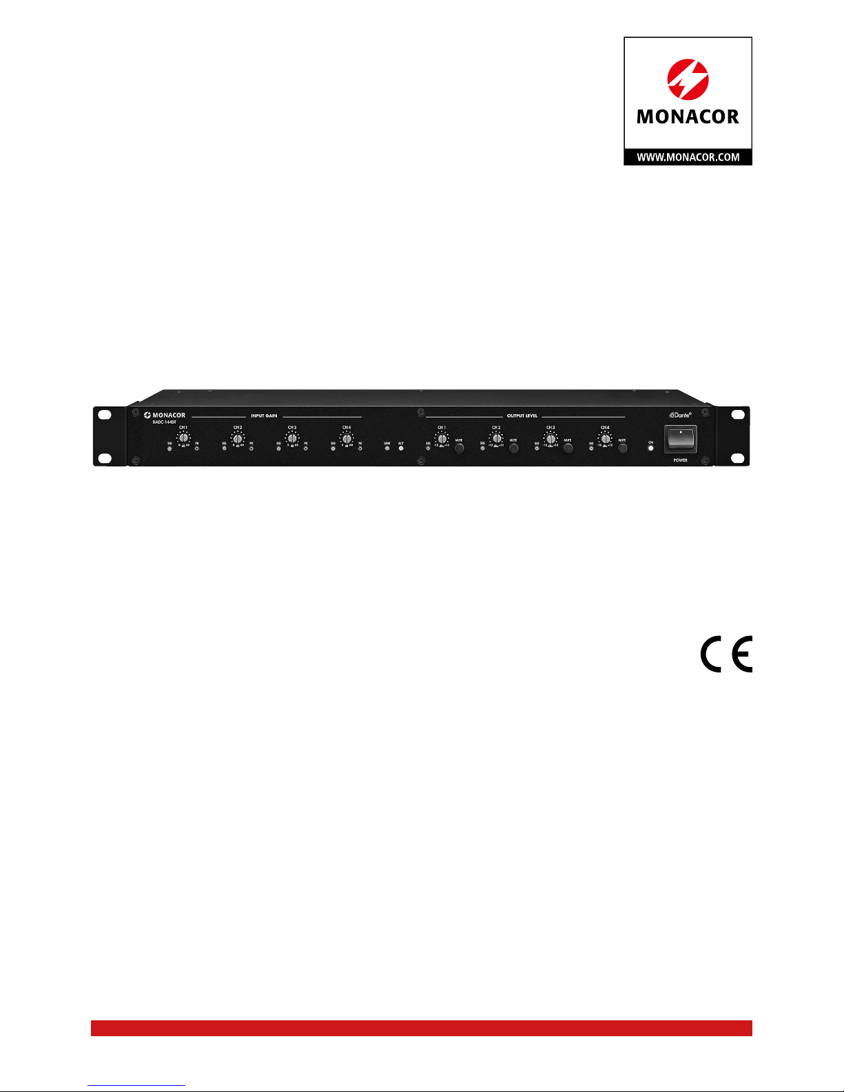
Signalwandler für DanteAudionetzwerke
Signal Converter for
Dante Audio Networks
DADC-144 DT
Bestell-Nr. • Order No. 25.7910
Page 2
2
DADC-144DT
INPUT GAIN OUTPUT LEVEL
ON
CH4
MUTE
CH3CH2CH1
CH4CH3CH2CH1
POWER
SIG LINK ACTSIG PK
dB
0 60
SIG PK
dB
0 60
SIG PK
0 60
PK
dB
0 60
SIG
dBu
-
12 +12
SIG
MUTE
dBu
-
12 +12
SIG
MUTE
dBu
-
12 +12
SIG
MUTE
dBu
-
12 +12
dB
➀
DADC-144DT
ON
CH 4
MUTE
CH 2CH 1
POWER
SIG SIG PK
0 60
PK
dB
0 60
SIG
dBu
-
12 +12
dB
Page 3

ELECTRONICS FOR SPECIALISTS ELECTRONICS FOR SPECIALISTS ELECTRONICS FOR SPECIALISTS ELECTRONICS FOR SPECIALISTS
3
Deutsch ...........Seite 4
English ............Page 8
Français ...........Page 12
Italiano............Pagina 16
Nederlands ........Pagina 20
Español ...........Página 20
Polski .............Strona 21
Dansk .............Sida 21
Svenska ...........Sidan 22
Suomi.............Sivulta 22
Page 4
DADC-144DT
INPUT GAIN OUTPUT LEVEL
ON
CH 4
MUTE
CH 3CH2CH 1
CH 4CH3CH 2CH1
POWER
SIG LINK ACTSIG PK
dB
0 60
SIG PK
dB
0 60
SIG PK
0 60
PK
dB
0 60
SIG
dBu
-
12 +1 2
SIG
MUTE
dBu
-
12 +1 2
SIG
MUTE
dBu
-
12 +1 2
SIG
MUTE
dBu
-
12 +1 2
dB
1 2 3 4 5 6 7 8 9 10
4
Deutsch
➁
Signalwandler für DanteAudionetzwerke
Diese Anleitung richtet sich an Installateure
von Audioanlagen mit Kenntnissen in der
Netzwerktechnik. Bitte lesen Sie diese Bedienungsanleitung vor dem Betrieb gründlich durch und heben Sie sie für ein späteres
Nachlesen auf.
1 Übersicht
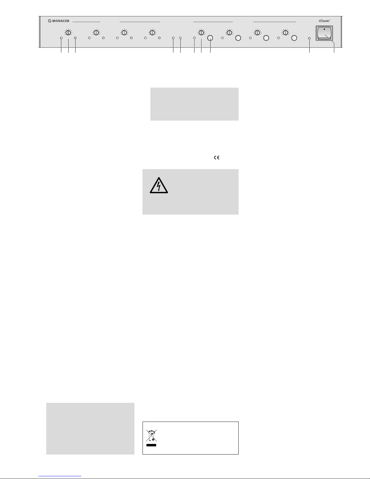
1.1 Frontseite
1
LED SIG leuchtet, wenn am jeweiligen
Eingang CH 1 bis CH 4 ein Signal anliegt
2
Regler zur Einstellung der Empfindlichkeit
des jeweiligen Eingangs CH 1 bis CH 4
3
LED PK leuchtet, wenn der maximal erlaubte Eingangspegel des jeweiligen Eingangs CH 1 bis CH 4 erreicht oder überschritten wird
Bei häufigem Aufleuchten die Eingangsverstärkung mit dem entsprechenden
Regler (2) reduzieren.
4 LED LINK zeigt eine Netzwerkverbindung
an
5 LED ACT zeigt Netzwerkaktivität an
6
LED SIG leuchtet, wenn am jeweiligen
Ausgang CH 1 bis CH 4 ein Signal anliegt
7 Regler zur Einstellung des Pegels für den
jeweiligen Ausgang CH 1 bis CH 4
8 Schalter MUTE zum Stummschalten des
jeweiligen Ausgangs CH 1 bis CH 4
9 Betriebsanzeige ON, leuchtet, sobald die
Ausgänge eingeschaltet sind
10 Ein- /Ausschalter POWER
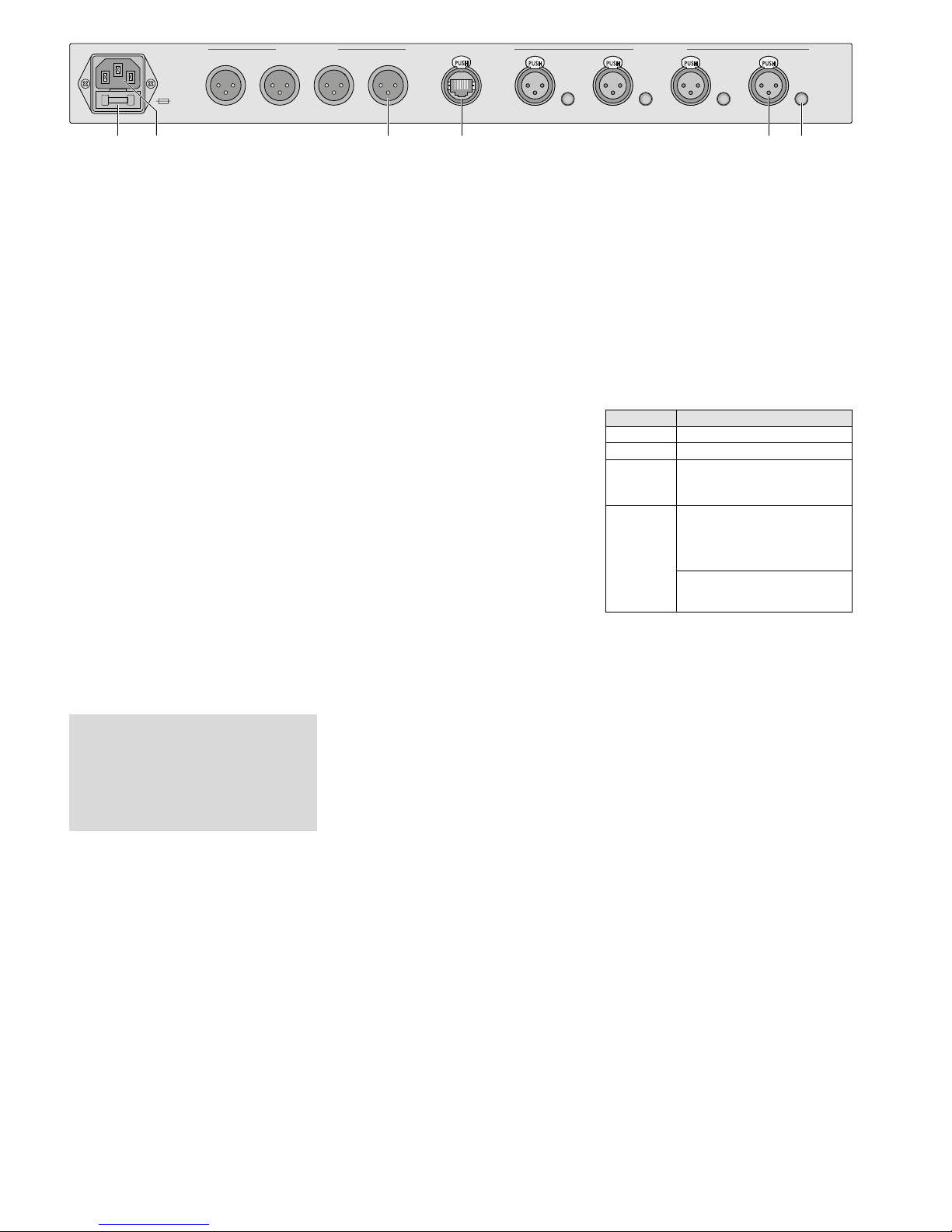
1.2 Rückseite
11 Halterung für die Netzsicherung;
eine geschmolzene Sicherung nur durch
eine gleichen Typs ersetzen
12
Netzbuchse zum Anschluss an eine Steckdose (230 V/ 50 Hz) über das beiliegende
Netzkabel
13 XLR-Ausgang jeweils für den Kanal CH 1
bis CH 4
14 RJ45-Buchse für den Netzwerkanschluss
15 XLR-Eingang jeweils für den Kanal CH 1
bis CH 4 zum Anschluss von Mikrofonen
oder Tonquellen mit Line-Pegel
Vorsicht! Bei eingeschalteter Phantomspeisung [zugehöriger Schalter (16) ist
eingerastet] wird die Buchse mit einer
48-V-Phantomspeisung versorgt. Es darf
in diesem Fall kein Mikrofon oder Audiogerät mit asymmetrischem Ausgangssignal angeschlossen sein, da dieses beschädigt werden kann.
16
Schalter PH. PWR zum Einschalten der
48-V-Phantomspeisung für den jeweiligen
Eingang CH 1 bis CH 4 (15)
Vorsicht! Die Schalter nur bei ausgeschaltetem Gerät betätigen, um Schaltgeräusche zu vermeiden. Bitte beachten Sie auch den Vorsichtshinweis der
Position 15.
2 Hinweise
fürdensicherenGebrauch
Das Gerät entspricht allen relevanten Richtlinien der EU und ist deshalb mit gekennzeichnet.
WARNUNG
Das Gerät wird mit lebensgefähr licher Netzspannung
versorgt. Nehmen Sie deshalb nie selbst Eingriffe daran
vor. Durch unsachgemäßes
Vorgehen besteht die Gefahr
eines elektrischen Schlages.
•
Verwenden Sie das Gerät nur im Innenbereich. Schützen Sie es vor Tropf- und
Spritzwasser sowie vor hoher Luftfeuchtigkeit. Der zulässige Einsatztemperaturbereich beträgt 0 – 40 °C.
•
Stellen Sie keine mit Flüssigkeit gefüllten
Gefäße, z. B. Trinkgläser, auf das Gerät.
•
Nehmen Sie das Gerät nicht in Betrieb und
ziehen Sie sofort den Netzstecker aus der
Steckdose:
1. wenn sichtbare Schäden am Gerät oder
am Netzkabel vorhanden sind,
2. wenn nach einem Sturz oder Ähnlichem
der Verdacht auf einen Defekt besteht,
3. wenn Funktionsstörungen auftreten.
Lassen Sie das Gerät in jedem Fall in einer
Fachwerkstatt reparieren.
•
Ziehen Sie den Netzstecker nie am Kabel
aus der Steckdose, fassen Sie immer am
Stecker an.
•
Verwenden Sie zum Reinigen nur ein trockenes, weiches Tuch, niemals Wasser oder
Chemikalien.
•
Wird das Gerät zweckentfremdet, falsch
angeschlossen, falsch bedient oder nicht
fachgerecht repariert, kann keine Haftung
für daraus resultierende Sach- oder Personenschäden und keine Garantie für das
Gerät übernommen werden.
Soll das Gerät endgültig aus dem
Betrieb genommen werden, übergeben Sie es zur umweltgerechten
Entsorgung einem örtlichen Recyclingbetrieb.
3 Einsatzmöglichkeiten
Dieser Signalwandler dient als Schnittstelle
zwischen analogen Audiogeräten und einem
Dante-Audionetzwerk. Er verfügt über vier
analoge Eingänge, an die sich Mikrofone oder
Tonquellen mit Line-Ausgangspegel anschließen lassen. Bei Bedarf kann eine 48-V-Phantomspeisung für jeden Eingang separat eingeschaltet werden. Für den Anschluss von
Lautsprecheranlagen, Aufnahmegeräten
oder Geräten zur Signalbearbeitung stehen
vier analoge Ausgänge zur Verfügung. Diese
können einzeln im Pegel angepasst und über
separate Schalter stummgeschaltet werden.
3.1 Dante
Dante ist ein von der Firma Audinate entwickeltes Audionetzwerk, bei dem es möglich
ist, bis zu 512 Audiokanäle gleichzeitig zu
übertragen. Dante (Digital Audio Network
Through Ethernet) nutzt einen verbreiteten
Ethernet-Standard und basiert auf dem Internet-Protokoll. Die Übertragung der Audiosignale erfolgt unkomprimiert, synchronisiert
und mit nur minimaler Latenz. Der Vorteil gegenüber analoger Audiosignalübertragung ist
eine kostengünstige Verbindung der Komponenten über Standard-Netzwerkkabel
und eine geringe Störanfälligkeit auch bei
langen Übertragungsstrecken. Zudem kann
die Signalführung zwischen einmal miteinander verbundenen Komponenten jederzeit
per Software geändert werden. Als Signalquellen dienen im Dante-Netzwerk Geräte,
die als Sender (Transmitter) eingerichtet sind.
Über das Programm „Dante Virtual Soundcard“ der Firma Audinate lassen sich auch
Computer als Signalquellen verwenden, um
z. B. auf dem Computer abgespielte Audiodateien in das Dante-Netzwerk einzuspeisen.
Geräte, die als Receiver eingerichtet sind (z. B.
Verstärker), empfangen die Signale aus dem
Dante-Netzwerk.
Der DADC-144DT verfügt über vier Transmitter-Kanäle (die Signale von den analogen
Eingängen) und vier Receiver-Kanäle (die
Signale zu den analogen Ausgängen). Die
Zuordnung der Transmitter und Receiver im
Dante-Netzwerk erfolgt über das Dante-Konfigurationsprogramm „Dante Controller“
(☞Kap. 7).
Die Konfiguration der Ethernet-Schnittstelle erfolgt ebenfalls über das Programm
„Dante Controller“ (☞Kap. 7.2). Für die
korrekte Einrichtung sind unbedingt Netzwerktechnik-Kenntnisse erforderlich.
Dante™ ist eine Handelsmarke von Audinate Pty Ltd.
Page 5
5
Deutsch
PUSH
1 2
3
1 2
3
1 2
3
1 2
3
2 1
3
PUSH
2 1
3
PUSH
2 1
3
PUSH
2 1
3
PUSH
230V~
50Hz
FUSE
OUTPUT SECTION NETWORK
CH 1
CH 4
CH 2CH 3CH 4
INPUT SECTION
CH 1CH 2CH 3
PH.PWR
MIC4
PH.PWR
MIC3
PH.PWR
MIC2
PH.PWR
MIC1
2 1
3
PUSH
2 1
3
PUSH
2 1
3
PUSH
2 1
3
PUSH
1211 13 14 15 16
➂
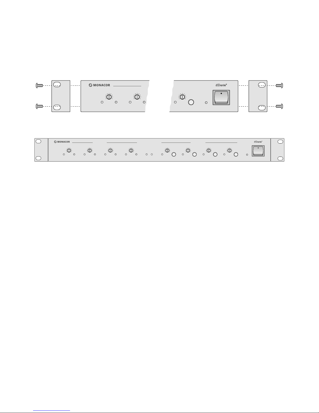
4 Aufstellen des Geräts
Das Gerät ist für den Einschub in ein Rack
(482 mm / 19”) vorgesehen, kann aber auch
als Tischgerät verwendet werden.
4.1 Rackeinbau
Für den Einbau in ein Rack die beiden mitgelieferten Montagewinkel an die Geräteseiten anschrauben (☞Abbildung 1). Im
Rack wird für das Gerät eine Höheneinheit
HE =44,45 mm benötigt.
5 Geräte anschließen
Alle Anschlüsse sollten bei ausgeschalteten
Geräten vorgenommen werden!
5.1 Eingänge
An die Eingangsbuchsen INPUT SECTION
(15) Mikrofone oder Tonquellen mit LineSig nalpegel (z. B. CD-Spieler, Vorverstärker,
Mischpult) anschließen. Die Buchsen sind für
symmetrische Signale beschaltet. Tonquellen
mit asymmetrischen Signalen können über
einen XLR-Stecker angeschlossen werden, bei
dem die Kontakte 1 und 3 verbunden sind.
Mit den Schaltern PH. PWR (16) kann für
jede Buchse eine 48-V-Phantomspeisung eingeschaltet werden, die für den Betrieb einiger
Mikrofone (z. B. Kondensatormikrofone) erforderlich ist. Zum Einschalten der Phantomspeisung den Schalter hineindrücken. Den
Schalter ausrasten, wenn die Tonquelle nicht
ausdrücklich Phantomspeisung benötigt.
Vorsicht! Bei eingeschalteter Phantomspeisung darf kein Mikrofon oder Audio gerät
mit asymmetrischem Ausgangs signal angeschlossen sein, da dieses beschädigt werden
kann. Die Schalter nur bei ausgeschaltetem
Gerät betätigen, um Schaltgeräusche zu vermeiden.
5.2 Ausgänge
An die Ausgänge OUTPUT SECTION (13) lassen sich Geräte mit Line-Pegel-Eingängen anschließen, z. B. Verstärker, Aktivlautsprecher,
Mischpulte, Aufnahmegeräte oder Geräte
zur Signalbearbeitung. Die Buchsen liefern
symmetrische Signale.
5.3 Netzwerk
Für den Anschluss an ein Dante-Netzwerk
die RJ45-Buchse NETWORK (14) mit einem
Ethernet-Switch verbinden, der mindestens
Fast-Ethernet (100-Mbit /s-Ethernet) unterstützt.
Die LED LINK (4) zeigt eine Netzwerkverbindung, die LED ACT (5) Netzwerkaktivität
an.
5.4 Stromversorgung
Zum Schluss das beiliegende Netzkabel zuerst in die Netzbuchse (12) und dann in eine
Steckdose (230 V/ 50 Hz) stecken.
6 Bedienung
1)
Vor dem ersten Einschalten zunächst die
Regler für die Eingangsempfindlichkeit
INPUTGAIN (2) und die Regler für den
Ausgangspegel OUTPUTLEVEL (7) mithilfe
eines kleinen Schraubendrehers auf Linksanschlag stellen.
2)
Erst die an den Eingängen (15) angeschlossenen Signalquellen einschalten, dann den
DADC-144DT mit dem Schalter POWER
(10) einschalten.
Nach dem Einschalten werden die
Ausgänge mit einer Verzögerung von
einigen Sekunden eingeschaltet. Erst dann
leuchtet die LED ON (9).
3) Die Empfindlichkeit der Eingänge mit den
Reglern INPUT GAIN (2) so einstellen, dass
die LED SIG (1) bei einem typischen Ein
gangssignal aufleuchtet und die LED PK (3)
nur bei Signalspitzen. Leuchtet die LED PK
dauernd auf, wird der Eingang übersteuert.
In diesem Fall die Eingangsempfindlichkeit
oder den Pegel der Signalquelle entsprechend reduzieren.
4)
Mit den Reglern OUTPUT LEVEL (7) den
Signalpegel der Ausgänge an die Eingangsempfindlichkeit der angeschlossenen
Geräte anpassen. Die LEDs SIG (6) leuchten, wenn ein Signal am Ausgang anliegt.
5) Mit den Schaltern MUTE (8) lassen sich die
Ausgänge einzeln stummschalten (Taste
einrasten). Zum Wiedereinschalten die
Taste wieder ausrasten.
6) Nach dem Betrieb zuerst die an den Ausgängen angeschlossenen Geräte ausschalten, danach den DADC-144DT und dann
die an den Eingängen angeschlossenen
Tonquellen.
7 Dante-Netzwerk einrichten
Die Einrichtung des DADC-144DT als Sender
und Empfänger im Dante-Netzwerk geschieht
über das Programm „Dante Controller“, das
über die Website der Firma Audinate kostenlos erhältlich ist. Die über das Programm
vorgenommenen Einstellungen werden in
den beteiligten Geräten des Dante-Netzwerks
gespeichert, sodass das Programm nur für
die Konfiguration des Netzwerks, nicht aber
während des normalen Betriebs erforderlich
ist. Für den Computer, auf dem das Programm
„Dante Controller“ laufen soll, gelten folgende System voraussetzungen:
Komponente Mindestvoraussetzungen
Prozessor 1 GHz
Arbeitsspeicher
512 MB
Netzwerk
Standard-Ethernet-Schnittstelle
(100 Mbit /s oder Gigabit) oder Wireless-
LAN-(Wi-Fi-)Schnitt stelle
Betriebssystem
Windows 7 (SP1 oder höher), 8.1 oder 10
Hinweis: Sowohl UTF-8 als auch Unicode wer-
den unterstützt, außer für Host- und Gerätenamen; der DNS-Standard unterstützt Unicode
für diese nicht.
Mac OS X 10.11.6, 10.12.6 oder 10.13
Hinweis: Nur Intel-Architektur, PPC-Architek-
tur wird nicht unterstützt.
Windows ist ein registriertes Warenzeichen der Microsoft
Corporation in den USA und anderen Ländern.
Mac OS ist ein registriertes Warenzeichen von Apple Inc.
in den USA und anderen Ländern.
7.1 Installation des Programms
„Dante Controller“
Zur Installation des Programms von der AudinateWebsite:
1) Die folgende Internet-Adresse aufrufen:
https://www.audinate.com/products/
software/dante-controller
2) Dort das Betriebssystem auswählen.
3) Den Button mit der Dante-Controller-Ver-
sion anklicken.
4) Einloggen bzw. einen Account erstellen.
5) Die Software herunterladen.
6) Die Software installieren.
Page 6
6
Deutsch
6
Deutsch
7.2 Gerätekonfiguration
mit dem Dante-Controller
1) Den Dante-Controller starten.
2) Warten, bis der DADC-144DT und die Ge-
räte, mit dem er verbunden werden soll, in
der Matrix erscheinen.
Hinweis: Ein Nichterscheinen des DADC-144DT
oder eines Verbindungspartners kann als Grund
haben, dass dasjenige Gerät
– nicht eingeschaltet ist,
– sich in einem anderen Subnetz befindet,
– sich nicht mit den anderen Dante- Geräten syn-
chronisieren kann.
Für einen der beiden zuletzt genannten Gründe
sollte das Dante-Gerät aber zumindest unter dem
Reiter „Device Info“ oder „Clock Status“ im Network-View aufgeführt werden. Ein Aus- und Wiedereinschalten des Geräts oder die Verbindungstrennung und Neuverbindung zum Switch könnte
eine schnelle Lösung des Problems bewirken. Wei
tere Informationen befinden sich im Benutzerhandbuch des Dante-Controllers von Audinate.
3)
In der Menüleiste des Dante-Controllers
„Device / Device View“ auswählen oder die
Tastenkombination Strg+D drücken. Das
Device-View-Fenster öffnet sich.
4)
In der unter der Menüleiste erscheinenden
Leiste im Drop-Down-Menü den „DADC144DT“ auswählen.
5)
In der dritten Leiste lassen sich unterschiedliche Informationen zu dem Gerät anzeigen
und Einstellungen vornehmen. Den Reiter
„Device Config“ auswählen (siehe Abbildung 4).
6)
Bei Bedarf die „Sample Rate“ an die zu
verbindenden Geräte anpassen oder eine
andere gemeinsame Sample-Rate für alle
Geräte festlegen.
7)
Im Feld „Rename Device“ kann der Name,
der im Dante-Netzwerk für das Gerät verwendet wird, geändert werden (z. B. auf
einen eindeutigen Namen mit einem Bezug
auf den Installationsort). Eine Änderung
mit „Apply“ bestätigen.
8) Über den Reiter „Network Config“ lassen
sich bei Bedarf die Netzwerkeinstellungen
für die Dante-Schnittstelle des DADC144DT ändern.
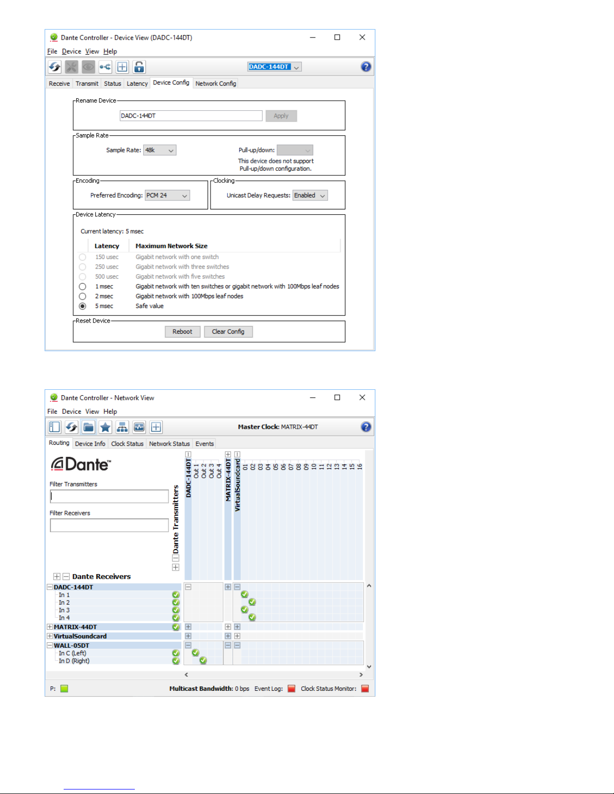
7.3 Routing mit dem Dante-Controller
Für die Zuweisung der Eingangs- und Ausgangssignale der beteiligten Geräte:
1)
Im „Network View“-Fenster unter „Routing“ die Kanäle des gewünschten Geräts
unter „Dante Transmitters“ sowie die Kanäle des gewünschten Verbindungspartners unter „Dante Receivers“ durch Klicken
auf das ⊞ öffnen (siehe Abbildung 5).
2)
Ausgehend von der Spalte des DanteTransmit-Kanals bis zur Zeile des gewünschten Dante-Receive-Kanals navigieren und
auf das Feld am Schnittpunkt klicken.
3)
Warten, bis das Feld einen grünen Kreis mit
weißem Haken ✔ anzeigt.
Für weitere Verbindungen die Schritte wiederholen.
Hinweis: Die Sendekanäle eines DADC-144DT können nicht mit den Empfangskanälen desselben Geräts
verbunden werden.
Auf der Audinate-Website kann zum DanteController ein englisches Benutzerhandbuch
(User Guide) heruntergeladen werden unter:
https://www.audinate.com/resources/
technical-documentation
8 Technische Daten
Eingänge CH1– CH 4
Empfindlichkeit: . . . . 5,7 mV – 2,3 V
Impedanz: . . . . . . . . 5,3 kΩ
Anschluss: . . . . . . . . XLR, symmetrisch
Phantomspannung: . 48 V, einzeln schalt-
bar
Ausgänge CH1– CH 4
max. Spannung: . . . . 2,3 V
Impedanz: . . . . . . . . 200 Ω
Anschluss: . . . . . . . . XLR, symmetrisch
Dante
Eingangskanäle: . . . . 4
Ausgangskanäle: . . . 4
Auflösung: . . . . . . . . 16 – 32 Bit
Abtastrate: . . . . . . . .44,1 – 96 kHz
Datenschnittstelle: . . Ethernet,
EtherCon-Buchse
RJ 45
Frequenzbereich: . . . . 20 – 20 000 Hz
Klirrfaktor: . . . . . . . . . < 0,005 %
Störabstand: . . . . . . . . > 90 dB
Einsatztemperatur: . . . 0 – 40 °C
Stromversorgung
Netzspannung: . . . . . 230 V/ 50 Hz
Leistungsaufnahme: . max. 15 VA
Abmessungen
Breite (mit Winkeln): . 434 mm (482 mm)
Höhe: . . . . . . . . . . . . 44,5 mm (1 HE)
Tiefe: . . . . . . . . . . . . 238 mm
Gewicht: . . . . . . . . . . . 3,3 kg
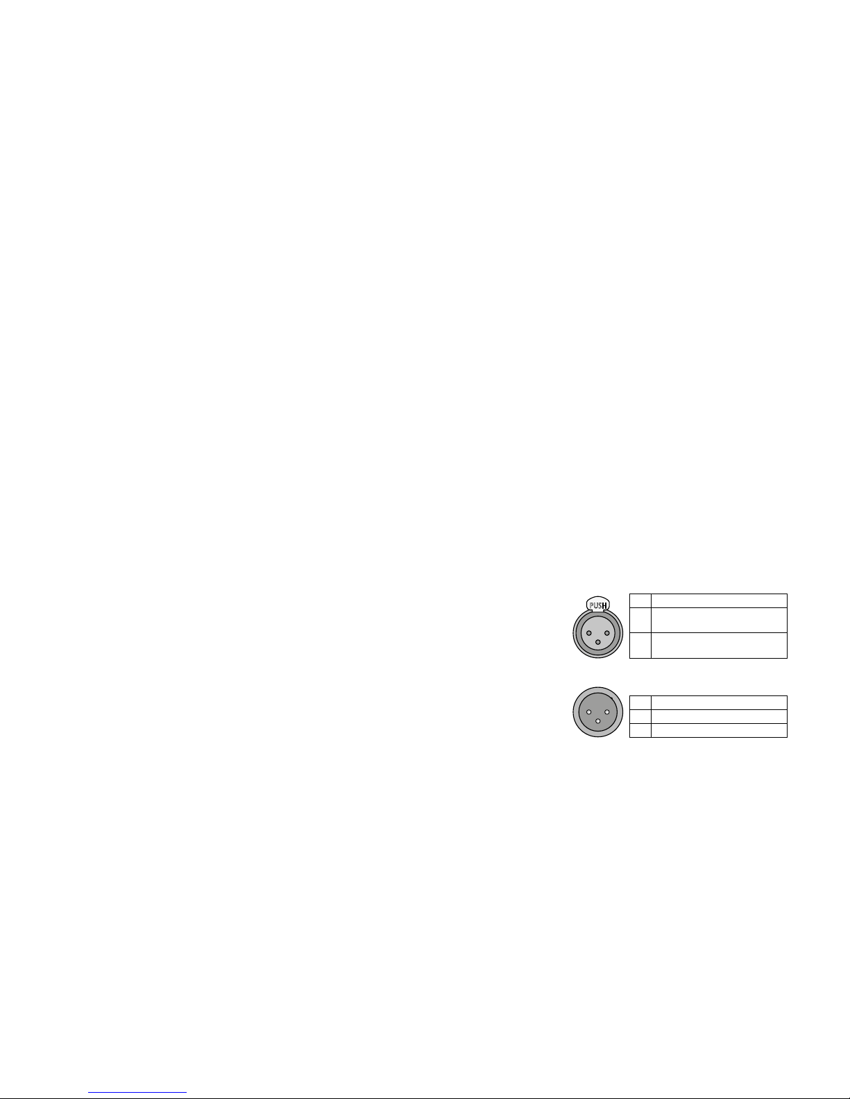
Belegung der Anschlüsse
Eingänge:
2 1
3
PUSH
1 Masse
2
Signal +, +48 V Phantomspei-
sung (schaltbar)
3
Signal −, +48 V Phantomspei-
sung (schaltbar)
Ausgänge:
1 2
3
1 Masse
2 Signal +
3 Signal −
Änderungen vorbehalten.
Page 7
7
Deutsch
7
Deutsch
➃
Device-View vom DADC-144DT
➄
Routing: „VirtualSoundcard“ ➧ „DADC-144DT“ und „DADC-144DT“ ➧ „WALL-05DT“
Diese Bedienungsanleitung ist urheberrechtlich für MONACOR ® INTERNATIONAL GmbH & Co. KG geschützt.
Eine Reproduktion für eigene kommerzielle Zwecke – auch auszugsweise – ist untersagt.
Page 8

DADC-144DT
INPUT GAIN OUTPUT LEVEL
ON
CH 4
MUTE
CH 3CH2CH 1
CH 4CH3CH 2CH1
POWER
SIG LINK ACTSIG PK
dB
0 60
SIG PK
dB
0 60
SIG PK
0 60
PK
dB
0 60
SIG
dBu
-
12 +1 2
SIG
MUTE
dBu
-
12 +1 2
SIG
MUTE
dBu
-
12 +1 2
SIG
MUTE
dBu
-
12 +1 2
dB
1 2 3 4 5 6 7 8 9 10
8
English
➁
Signal Converter for Dante
AudioNetworks
These instructions are intended for installers
of audio systems with knowledge in network
technology. Please read the instructions
carefully prior to operation and keep them
for later reference.
1 Overview
1.1 Front panel
1
LED indicator SIG, will light up when a
signal is available at the corresponding
input CH 1 to CH 4
2
Control to adjust the sensitivity of the
corresponding input CH 1 to CH 4
3 LED indicator PK, will light up when the
maximum input level allowed of the corresponding input CH 1 to CH 4 has been
reached or exceeded
When the LED indicator lights up frequently, reduce the input gain by means
of the corresponding control (2).
4 LED indicator LINK, will light up when a
network connection has been established
5
LED indicator ACT, will light up to indicate
network activity
6
LED indicator SIG, will light up when a
signal is available at the corresponding
output CH 1 to CH 4
7 Control to adjust the level for the corre-
sponding output CH 1 to CH 4
8 Switch MUTE to mute the corresponding
output CH 1 to CH 4
9 Power indicator ON, will light up as soon
as the outputs have been switched on
10 POWER switch
1.2 Rear panel
11 Support for the mains fuse;
always replace a blown fuse by one of
the same type
12
Mains jack for connection to a mains
socket (230 V/ 50 Hz) by means of the
mains cable supplied
13 XLR output, one each for channels CH 1
to CH 4
14 RJ45 jack for network connection
15 XLR input, one each for channels CH 1 to
CH 4, to connect microphones or audio
sources with line level
Caution! When the phantom power
supply is activated [corresponding
switch (16) engaged], the jack will be
supplied with 48 V phantom power.
Never connect a microphone or audio
source with unbalanced output signal
when the phantom power supply is
activated; otherwise, the microphone or
audio source may be damaged.
16
Switch PH.PWR to activate the 48 V phantom power supply for the corresponding
input CH 1 to CH 4 (15)
Caution: To prevent switching noise,
use the switches only when the unit is
switched off. Also observe the caution
note in item 15!
2 Safety Notes
The unit corresponds to all relevant directives
of the EU is therefore marked with .
WARNING
The unit uses dangerous
mains voltage. Leave servicing to skilled personnel only.
Inexpert handling of the unit
may result in electric shock.
•
The unit is suitable for indoor use only. Pro
tect it against dripping water, splash water
and high air humidity. The admissible ambient temperature range is 0 – 40 °C.
•
Do not place any vessel filled with liquid on
the unit, e. g. a drinking glass.
•
Do not operate the unit and immediately
disconnect it from the mains socket
1.
if the unit or the mains cable is visibly
damaged,
2. if a defect might have occurred after the
unit was dropped or suffered a similar
accident,
3. if malfunctions occur.
In any case the unit must be repaired by
skilled personnel.
•
Never pull the mains cable to disconnect
the mains plug from the mains socket, always seize the plug.
•
For cleaning only use a dry, soft cloth; never
use water or chemicals.
•
No guarantee claims for the unit and no liability for any resulting personal damage or
material damage will be accepted if the unit
is used for other purposes than originally
intended, if it is not correctly connected
or operated, or if it is not repaired in an
expert way.
If the unit is to be put out of operation definitively, take it to a local
recycling plant for a disposal which
is not harmful to the environment.
3 Applications
This signal converter is used as an interface
between analog audio units and a Dante
audio network. It provides four analog inputs
for the connection of microphones or audio
sources with line output level. If required, a
48 V phantom power supply can be activated
separately for each input. Four analog outputs are available to connect speaker systems,
recorders or units for signal processing; their
level can be adjusted individually and they
can be muted by means of separate switches.
3.1 Dante
Dante, an audio network developed by the
company Audinate, allows transmission of
up to 512 audio channels at the same time.
Dante (Digital Audio Network Through
Ethernet) uses a common Ethernet standard
and is based on the Internet protocol. The
transmission of audio signals is uncompressed
and synchronized, with minimum latency.
The advantage over analog audio signal
transmission is a cost-effective connection
of components via standard network cables
and low susceptibility to interference, even in
case of long transmission paths. In addition,
signal routing between components that have
once been connected can be changed by software at any time. In the Dante network, units
configured as transmitters are used as signal
sources. By means of the program “Dante
Virtual Soundcard” from the company Audinate, it is also possible to use computers as
signal sources and thus to feed audio files replayed on the computer to the Dante network.
Units configured as receivers (e. g. amplifiers)
receive the signals from the Dante network.
The signal converter DADC-144DT provides four transmitter channels (the signals of
the analog inputs) and four receiver channels
(the signals to the analog outputs). The transmitters and the receivers are assigned in the
Dante network via the Dante configuration
program “Dante Controller” (☞chapter 7).
The Ethernet interface is also configured
via the program “Dante Controller” (☞chapter 7.2). For correct configuration, knowledge
in network technology is indispensable.
Dante™ is a trademark of Audinate Pty Ltd.
Page 9

9
English
PUSH
1 2
3
1 2
3
1 2
3
1 2
3
2 1
3
PUSH
2 1
3
PUSH
2 1
3
PUSH
2 1
3
PUSH
230V~
50Hz
FUSE
OUTPUT SECTION NETWORK
CH 1
CH 4
CH 2CH 3CH 4
INPUT SECTION
CH 1CH 2CH 3
PH.PWR
MIC4
PH.PWR
MIC3
PH.PWR
MIC2
PH.PWR
MIC1
2 1
3
PUSH
2 1
3
PUSH
2 1
3
PUSH
2 1
3
PUSH
1211 13 14 15 16
➂
4 Setting up the Unit
The unit is designed for installation into a rack
(482 mm / 19”); however, it can also be used
as a tabletop unit.
4.1 Rack installation
For rack installation, screw the two mounting
brackets supplied onto the right and left sides
of the unit (☞fig. 1). In the rack, 1 rack
space (= 44.45 mm) is required.
5 Connecting Units
Prior to making any connection, switch off
the units to be connected.
5.1 Inputs
Connect microphones or audio sources with
line signal level (e. g. CD player, preamplifier,
mixer) to the input jacks INPUT SECTION (15).
The jacks are designed for balanced signals.
Audio sources with unbalanced signals can
be connected via an XLR plug where the contacts1 and 3 are connected with each other.
By means of the switches PH.PWR (16),
individual jacks can be supplied with 48 V
phantom power which some microphones
(e. g. condenser microphones) require for
operation. To activate the phantom power
supply, engage the switch. Disengage the
switch unless the audio source definitely
requires phantom power.
Caution! When the phantom power supply has been activated, make sure that no
microphone or audio unit with unbalanced
output signal has been connected to the
input; the microphone or audio unit may be
damaged. To avoid switching noise, only use
the switches when the unit is switched off.
5.2 Outputs
The inputs OUTPUT SECTION (13) can be used
to connect units with line level inputs such as
amplifiers, active speakers, mixers, recorders
or units for signal processing. The jacks provide balanced signals.
5.3 Network
For connection to a Dante network, connect
the RJ45 jack NETWORK (14) to an Ethernet
switch which supports at least Fast Ethernet
(100MBits / s Ethernet).
The LED indicator LINK (4) will light up
when a network connection has been established; the LED indicator ACT (5) will light up
to indicate network activity.
5.4 Power supply
Finally, connect the mains cable supplied to
the mains jack (12) and then to a mains socket
(230 V/ 50 Hz).
6 Operation
1)
Prior to initial switch-on, use a small screwdriver to set the controls for sensitivity adjustment INPUT GAIN (2) and the controls
OUTPUT LEVEL (7) to the left stop.
2)
First switch on the signal sources connected to the inputs (15), then switch on
the signal converter DADC-144DT with the
POWER switch (10).
After switch-on, the outputs will be
switched on with a delay of a few seconds;
then the LED indicator ON (9) will light up.
3) Use the controls INPUT GAIN (2) to adjust
the sensitivity of the inputs in such a way
that the LED indicator SIG (1) will light with
typical input signals and the LED indicator
PK (3) will only light up with signal peaks.
The LED indicator PK will light up continuously when the input is overloaded. In
this case, reduce the input sensitivity or
the level of the signal source accordingly.
4)
Use the controls OUTPUT LEVEL (7) to
match the signal level of the outputs to the
input sensitivity of the units connected. The
LED indicators SIG (6) will light up when a
signal is available at the output.
5)
Use the switches MUTE (8) to mute the
corresponding outputs (engage the button). To unmute an output, disengage the
corresponding button.
6) After operation, first switch off the units
connected to the outputs, then the signal
converter DADC-144DT and finally the
audio sources connected to the inputs.
7 Configuration of the
DanteNetwork
The signal converter DADC-144DT is set up as
transmitter and receiver in the Dante network
by means of the program “Dante Controller”,
available as a free download on the website of the company Audinate. The settings
made via the program will be saved in the
corresponding units of the Dante network so
that the program is only required for network
configuration but not for normal operation.
The following system requirements apply to
the computer on which the program “Dante
Controller” is to be executed:
Component Minimum requirements
Processor 1 GHz
RAM 512 MB
Network
Standard Ethernet interface
(100 Mbit / s or Gigabit) or wireless LAN
(WiFi) interface
Operating
system
Windows 7 (SP1 or higher), 8.1 or 10
Note: Both UTF-8 and Unicode will be sup-
ported, except for host names and names
of units; the DNS standard will not support
Unicode for them.
Mac OS X 10.11.6, 10.12.6 or 10.13
Note: Intel architecture only; PPC architecture
will not be supported.
Windows is a registered trademark of Microsoft Corporation in the USA and other countries.
Mac OS is a registered trademark of Apple Inc. in the USA
and other countries.
7.1 Installing the “Dante Controller”
To install the program from the Audinate
website:
1) Call up the following Internet address:
https://www.audinate.com/products/
software/dante-controller
2) Select the operating system.
3)
Click the button with the version of the
Dante controller.
4) Log in or create an account.
5) Download the software.
6) Install the software.
Page 10

10
English
10
English
7.2 Configuration of the unit
with the Dante Controller
1) Start the Dante Controller.
2)
Wait for the signal converter DADC-144DT
and the units to which it is to be connected
to appear in the matrix.
Note: If the signal converter DADC-144DT or a
connection partner fails to appear in the list, the
reason may be that the unit
– has not been switched on,
– is in a different subnet,
– is not able to synchronize with the other Dante
units.
However, if one of the two last-mentioned reasons
applies, the Dante unit should at least appear under
the tab “Device Info” or “Clock Status” in the network view. A fast solution of this problem may be
to switch the unit off and on or to disconnect and
re-establish the connection to the network switch.
For further information please refer to the user
manual of the Dante Controller from Audinate.
3) In the menu bar of the Dante Controller,
select “Device / Device View” or use the
shortcut Ctrl+D. The Device View window
will open.
4)
Select “DADC-144DT” in the bar of the
drop-down menu appearing beneath the
menu bar.
5)
The third bar can be used to indicate information on the unit and to make settings.
Select the tab “Device Config” (see fig. 4).
6) Adjust the “Sample Rate” to the desired
connection partner or set a different common sample rate for both units, if required.
7)
In the field “Rename Device”, the name
used for the unit in the Dante network
can be changed (e. g. to a specific name
referring to the place of installation). Click
“Apply” to confirm the change.
8) Use the tab “Network Config” to change
the network settings for the Dante interface of DADC-144DT, if required.
7.3 Routing with the Dante Controller
To assign the input signals and output signals
of the corresponding units:
1)
Under “Routing” in the window “Network
View”, click ⊞ to open the channels of the
desired unit under “Dante Transmitters”
and the channels of the desired connection partner under “Dante Receivers” (see
fig.5).
2)
Navigate from the column of the Dante
transmit channel to the line of the desired
Dante receive channel and click the field
at the intersection point.
3)
Wait for the field to show a green circle
with a white check mark ✔.
Repeat the steps for additional connections.
Note: The transmitting channels of a DADC-144DT
cannot be connected to the reception channels of
the same unit.
An English user guide for the Dante Controller
is available for download on the Audinate
website:
https://www.audinate.com/resources/
technical-documentation
8 Specifications
Inputs CH 1 – CH 4
Sensitivity: . . . . . . . . 5.7 mV – 2.3 V
Impedance: . . . . . . . 5.3 kΩ
Connection: . . . . . . . XLR, balanced
Phantom power: . . . . 48 V, can be acti-
vated separately for
each input
Outputs CH 1 – CH 4
Max. voltage: . . . . . . 2.3 V
Impedance: . . . . . . . 200 Ω
Connection: . . . . . . . XLR, balanced
Dante
Input channels: . . . . . 4
Output channels: . . . 4
Resolution: . . . . . . . .16 – 32 bit
Sampling rate: . . . . . 44.1 – 96 kHz
Data interface: . . . . . Ethernet,
EtherCon jack RJ 45
Frequency range: . . . . 20 – 20 000 Hz
THD: . . . . . . . . . . . . . . < 0.005 %
S / N ratio: . . . . . . . . . . > 90 dB
Ambient temperature: 0 – 40 °C
Power supply
Mains voltage: . . . . . 230 V/ 50 Hz
Power consumption: . 15 VA max.
Dimensions
Width
(with brackets): . . . . . 434 mm (482 mm)
Height: . . . . . . . . . . . 44.5 mm (1 RS)
Depth: . . . . . . . . . . . 238 mm
Weight: . . . . . . . . . . . 3.3 kg
Pin configuration
Inputs:
2 1
3
PUSH
1 Ground
2
Signal +, +48 V phantom
power (can be activated)
3
Signal −, +48 V phantom
power (can be activated)
Outputs:
1 2
3
1 Ground
2 Signal +
3 Signal −
Subject to technical modification.
Page 11

11
English
11
English
➃
Device View of DADC-144DT
➄
Routing: “VirtualSoundcard” ➧ “DADC-144DT” and “DADC-144DT” ➧ “WALL-05DT”
All rights reserved by MONACOR ® INTERNATIONAL GmbH & Co. KG.
No part of this instruction manual may be reproduced in any form or by any means forany commercial use.
Page 12

DADC-144DT
INPUT GAIN OUTPUT LEVEL
ON
CH 4
MUTE
CH 3CH2CH 1
CH 4CH3CH 2CH1
POWER
SIG LINK ACTSIG PK
dB
0 60
SIG PK
dB
0 60
SIG PK
0 60
PK
dB
0 60
SIG
dBu
-
12 +1 2
SIG
MUTE
dBu
-
12 +1 2
SIG
MUTE
dBu
-
12 +1 2
SIG
MUTE
dBu
-
12 +1 2
dB
1 2 3 4 5 6 7 8 9 10
12
Français
➁
Convertisseur de signal pour
réseau audio Dante
Cette notice s’adresse aux installateurs de
systèmes audio avec des connaissances en
technologie réseau. Veuillez lire la présente
notice avec attention avant le fonctionnement
et conservez-la pour pouvoir vous y reporter
ultérieurement.
1 Présentation
1.1 Face avant
1
LED SIG : brille lorsqu’un signal est présent
à l’entrée correspondante CH 1 à CH 4
2 Réglage de la sensibilité de l’entrée cor-
respondante CH 1 à CH 4
3 LED PK : brille lorsque le niveau d’entrée
maximal de l’entrée correspondante CH 1
à CH 4 est atteint ou dépassé
Si la LED brille fréquemment, diminuez le
niveau d’entrée avec le réglage (2) correspondant.
4 LED LINK : indique une connexion réseau
5 LED ACT : indique une activité réseau
6
LED SIG : brille lorsqu’un signal est présent
à la sortie correspondante CH 1 à CH 4
7 Réglage du niveau pour la sortie corres-
pondante CH 1 à CH 4
8
Interrupteur MUTE pour couper le son de
la sortie correspondante CH 1 à CH 4
9
Témoin de fonctionnement ON : brille dès
que les sorties sont allumées
10 Interrupteur Power Marche /Arrêt
1.2 Face arrière
11 Porte fusible :
tout fusible fondu doit impérativement
être remplacé par un fusible de même
type
12
Prise secteur à brancher, via le cordon secteur livré, à une prise 230 V/ 50 Hz
13 Sortie XLR respectivement pour le canal
CH 1 à CH 4
14 Prise RJ45 pour la connexion réseau
15 Entrée XLR respectivement pour le canal
CH 1 à CH 4 pour brancher des microphones ou sources de signal avec niveau
ligne
Attention ! Lorsque l’alimentation
fantôme est activée [interrupteur correspondant (16) enclenché], la prise est
alimentée par une alimentation fantôme
48 V. En aucun cas, vous ne devez brancher de microphone ou appareil audio
avec un signal de sortie asymétrique car
il peut être endommagé.
16
Interrupteur PH.PWR pour allumer l’alimentation fantôme 48 V pour l’entrée
correspondante CH 1 à CH 4 (15)
Attention ! N’activez les interrupteurs
que lorsque l’appareil est éteint pour
éviter tous les bruits de commutation.
Reportez-vous au conseil du point 15.
2 Conseils d’utilisation et
desécurité
L’appareil répond à toutes les directives nécessaires de l’Union européenne et porte donc
le symbole .
AVERTISSEMENT L’appareil est alimenté par
une tension dangereuse.
Ne touchez jamais l’intérieur de l’appareil car, en
cas de mauvaise manipulation, vous pouvez subir
une décharge électrique.
•
L’appareil n’est conçu que pour une utilisation en intérieur. Protégez-le des éclaboussures, de tout type de projections d’eau et
d’une humidité d’air. La température ambiante admissible est de 0 – 40 °C.
•
En aucun cas, vous ne devez pas poser
d’objet contenant du liquide ou un verre
sur l’appareil.
•
Ne faites pas fonctionner l’appareil et débranchez-le immédiatement du secteur
dans les cas suivants :
1. l’appareil ou le cordon secteur présente
des dommages visibles.
2.
après une chute ou accident similaire,
vous avez un doute sur l’état de l’appareil.
3. des dysfonctionnements apparaissent.
Dans tous les cas, les dommages doivent
être réparés par un technicien spécialisé.
•
Ne débranchez jamais l’appareil en tirant
sur le cordon secteur ; retirez toujours le
cordon secteur en tirant la fiche.
•
Pour le nettoyage, utilisez un chiffon sec et
doux, en aucun cas de produits chimiques
ou d’eau.
•
Nous déclinons toute responsabilité en
cas de dommages corporels ou matériels
résultants si l’appareil est utilisé dans un
but autre que celui pour lequel il a été
conçu, s’il n’est pas correctement branché
ou utilisé ou s’il n’est pas réparé par une
personne habilitée ; en outre, la garantie
deviendrait caduque.
Lorsque l’appareil est définitivement
retiré du service, vous devez le déposer dans une usine de recyclage
de proximité pour contribuer à son
élimination non polluante.
3 Possibilités d’utilisation
Ce convertisseur de signal sert d’interface
entre les appareils audio analogiques et un
réseau audio Dante. Il dispose de quatre
entrées analogiques sur lesquelles on peut
brancher des microphones ou sources de signal avec niveau de sortie ligne. Si besoin,
une alimentation fantôme 48 V peut être allumée séparément pour chaque entrée. Pour le
branchement d’installations de haut-parleurs,
enregistreurs ou appareils pour le traitement
de signal, quatre sorties analogiques sont
prévues. Leur niveau peut être réglé individuellement et le son peut être coupé via des
interrupteurs séparés.
3.1 Dante
Dante est un réseau audio développé par la
société Audinate avec lequel il est possible
de transmettre simultanément jusqu’à 512
canaux audio. Dante (Digital Audio Network
Through Ethernet) utilise un standard Ethernet répandu et se base sur le protocole Internet. La transmission des signaux audio se fait
de manière non compressée, synchronisée et
avec une latence minimale. L’avantage par
rapport à une transmission analogique de signal audio est la connexion des composants
via un câble réseau standard à un prix faible et
une faible sensibilité aux interférences même
pour de longues distances. De plus, la transmission du signal entre les composants reliés
entre eux peut à tout moment être modifiée
via le logiciel. Dans le réseau Dante, les appareils installés comme émetteurs (Transmitter)
servent de source de signal. Via le programme
«Dante Virtual Soundcard» de la société
Audinate, on peut également utiliser des
ordinateurs comme sources de signal, pour,
par exemple, insérer dans le réseau Dante, des
fichiers audio lus sur l’ordinateur. Les appareils installés comme récepteur (Receiver), par
exemple amplificateurs, reçoivent les signaux
du réseau Dante.
Le DADC-144DT dispose de quatre canaux Transmitters (les signaux des entrées
analogiques) et de quatre canaux Receivers
(les signaux vers les sorties analogiques). L’attribution des Transmitters et Receivers dans
le réseau Dante se fait via le programme
de configuration Dante «Dante Controller»
(☞chapitre 7).
La configuration de l’interface Ethernet
se fait également via le programme «Dante
Controller» (☞chapitre 7.2). Pour une configuration correcte, des connaissances réseau
sont indispensables.
Dante™ est une marque déposée de Audinate Pty Ltd.
Page 13

13
Français
PUSH
1 2
3
1 2
3
1 2
3
1 2
3
2 1
3
PUSH
2 1
3
PUSH
2 1
3
PUSH
2 1
3
PUSH
230V~
50Hz
FUSE
OUTPUT SECTION NETWORK
CH 1
CH 4
CH 2CH 3CH 4
INPUT SECTION
CH 1CH 2CH 3
PH.PWR
MIC4
PH.PWR
MIC3
PH.PWR
MIC2
PH.PWR
MIC1
2 1
3
PUSH
2 1
3
PUSH
2 1
3
PUSH
2 1
3
PUSH
1211 13 14 15 16
➂
4 Positionnement de l’appareil
L’appareil est prévu pour une installation dans
un rack 482 mm, 19”, il peut également être
posé sur une table.
4.1 Installation en rack
Pour un montage en rack, vissez les deux
étriers de montage livrés sur les côtés de l’appareil (☞schéma 1). Dans le rack, 1 unité
(1unité = 44,5 mm) est nécessaire pour l’appareil.
5 Branchements des appareils
Tous les branchements ne doivent être effectués que lorsque les appareils sont éteints !
5.1 Entrées
Reliez des microphones ou sources audio
avec niveau de sortie ligne (p. ex. lecteur CD,
préamplificateur, table de mixage) aux prises
d’entrée INPUT SECTION (15). Les prises sont
prévues pour des signaux symétriques. Il est
possible de relier des sources audio avec signaux asymétriques via une fiche XLR sur
laquelle les contacts 1 et 3 sont reliés.
Avec les interrupteurs PH.PWR (16), il est
possible d’activer pour chaque prise, une alimentation fantôme 48 V indispensable pour le
fonctionnement de certains microphones (par
exemple microphones à condensateur). Pour
allumer l’alimentation fantôme, appuyez sur
l’interrupteur ; si la source audio ne nécessite
pas d’alimentation fantôme impérativement,
désenclenchez l’interrupteur.
Attention ! Lorsque l’alimentation fantôme
est allumée, ne branchez aucun microphone
ou appareil audio avec signal de sortie asymétrique car il peut être endommagé. N’activez les interrupteurs que lorsque l’appareil
est éteint pour éviter tout bruit fort de commutation.
5.2 Sorties
On peut relier aux sorties OUTPUT SECTION
(13) des appareils avec entrées niveau ligne,
par exemple amplificateur, enceinte active,
table de mixage, enregistreurs ou appareils
pour traitement de signal. Les prises délivrent
des signaux symétriques.
5.3 Réseau
Pour le branchement à un réseau Dante, reliez
la prise RJ45 NETWORK (14) avec un Switch
Ethernet acceptant Fast Ethernet (Ethernet
100 Mbits/s) au moins.
La LED LINK (4) indique une connexion réseau, la LED ACT (5) indique l’activité réseau.
5.4 Alimentation
Pour terminer, reliez le cordon secteur livré à la
prise secteur (12) et à une prise 230 V/ 50 Hz.
6 Utilisation
1)
Avant la première mise sous tension,
mettez tout d’abord les réglages pour la
sensibilité d’entrée INPUT GAIN (2) et les
réglages pour le niveau de sortie OUTPUT
LEVEL (7) sur la butée de gauche en vous
aidant d’un petit tournevis.
2) Allumez tout d’abord les sources de signal
reliées aux entrées (15), puis allumez le
DADC-144DT avec l’interrupteur POWER
(10).
Après l’allumage, les sorties sont allumées avec une temporisation de quelques
secondes. Ensuite la LED ON (9) brille.
3)
Réglez la sensibilité des entrées avec les
réglages INPUT GAIN (2) de telle sorte que
la LED SIG (1) brille pour un signal d’entrée
typique et que la LED PK (3) ne brille que
pour des pointes de signal. Si la LED PK
brille en continu, l’entrée est en surcharge.
Dans ce cas, diminuez la sensibilité d’entrée ou le niveau de la source de signal en
conséquence.
4)
Avec les réglages OUTPUT LEVEL (7), adaptez le niveau du signal des sorties à la sensibilité d’entrée des appareils reliés. Les LEDs
SIG (6) brillent lorsqu’un signal est présent
à la sortie.
5) Avec les interrupteurs MUTE (8), on peut
couper séparément le son des sorties
(touche enfoncée). Pour réactiver le son,
désenclenchez la touche.
6)
Après le fonctionnement, éteignez tout
d’abord les appareils reliés aux sorties,
puis le DADC-144DT et ensuite les sources
audio reliées aux entrées.
7 Créer un réseau Dante
L’installation du DADC-144DT comme émetteur et récepteur dans le réseau Dante se fait
via le programme «Dante Controller» disponible gratuitement via le site internet de
la société Audinate. Les réglages effectués
via le programme sont mémorisés dans les
émetteurs et récepteurs participants du réseau Dante de telle sorte que le programme
ne soit nécessaire que pour la configuration
du réseau et pas pendant le fonctionnement
normal. Pour l’ordinateur, sur lequel le programme «Dante Controller» doit fonctionner, il faut suivre les configurations système
suivantes :
Composants Configuration minimale
Processeur 1 GHz
Mémoire de
travail
512 MBytes
Réseau
Interface Ethernet standard
(100 Mbit /s ou Gigabit) ou
interface LAN sans fil (Wi-Fi)
Système
d’exploitation
Windows 7 (SP1 ou supérieur), 8.1 ou 10
Remarque : UTF-8 et Unicode supportés, sauf
pour nom hôte et nom appareil ; le standard
DNS n’accepte pas Unicode pour ceux-ci.
Mac OS X 10.11.6, 10.12.6 ou 10.13
Remarque : uniquement architecture Intel,
architecture PCC non acceptée.
Windows est une marque déposée de Microsoft Corporation aux Etats-Unis et dans les autres pays.
Mac OS est une marque déposée de Apple Inc. aux EtatsUnis et dans les autres pays.
7.1 Installer le programme
«DanteController»
Pour installer le programme depuis le site
internet de Audinate :
1) Allez à l’adresse internet suivante :
https://www.audinate.com/products/
software/dante-controller
2) Sélectionnez le système d’exploitation.
3)
Cliquez sur le bouton avec la version du
contrôleur Dante.
4) Connectez-vous ou créez un compte.
5) Téléchargez le logiciel.
6) Installez le logiciel.
Page 14

14
Français
14
Français
7.2 Configurer l’appareil avec
leDanteController
1) Démarrez le Dante Controller.
2) Attendez jusqu’à ce que le DADC-144DT
et les appareils auxquels il doit être relié,
s’affichent dans la matrice.
Remarque : Si le DADC-144DT ou un partenaire
de connexion n’apparaît pas, la raison peut être :
– l’appareil n’est pas allumé,
– se trouve dans un autre sous-réseau,
– ne peut pas être synchronisé avec les autres ap-
pareils Dante.
Pour une des deux raisons citées en dernier, il faut
que l’appareil Dante soit présenté au moins dans
la visualisation Network sous l’onglet «Device
Info» ou «Clock Status». Arrêter puis redémarrer
ou couper la liaison vers le Switch puis la réactiver
pourrait être une solution rapide au problème. Vous
trouverez des informations complémentaires dans
la notice du Dante Controller de Audinate.
3) Dans la barre de menu du Dante Controller, sélectionnez «Device/Device View» ou
appuyez sur la combinaison de touches
Ctrl+D. La fenêtre «Device View» s’affiche.
4) Dans la barre s’affichant sous la barre de
menu, dans le menu déroulant, sélectionnez le «DADC-144DT».
5) Dans la troisième barre, différentes informations sur l’appareil s’affichent et on
peut effectuer des réglages. Sélectionnez
l’onglet «Device Config» (voir schéma 4).
6)
Si besoin, adaptez le «Sample Rate» au
partenaire de connexion souhaité ou définissez un autre Sample Rate (taux d’échantillonnage) commun pour les deux appareils.
7)
Dans le champ «Rename Device», il est
possible de modifier le nom utilisé pour
l’appareil dans le réseau Dante (par
exemple un nom unique en rapport avec
le lieu d’installation). Confirmez toute modification avec «Apply».
8) Via l’onglet «Network Config», vous pouvez si besoin modifier les réglages réseau
pour l’interface Dante du DADC-144DT.
7.3 Routage avec le Dante Controller
Pour attribuer les signaux d’entrée et de sortie
des appareils correspondants :
1)
Dans la fenêtre «Network View», sous
«Routing», ouvrez les canaux de l’appareil
souhaité sous «Dante Transmitters» et les
canaux du partenaire de connexion souhaité sous «Dante Receivers», en cliquant
sur le symbole ⊞ (voir schéma 5).
2) Naviguez à partir de la colonne du canal
Dante Transmit jusqu’à la ligne du canal
Dante Receiver souhaité et cliquez sur le
champ au point d’intersection.
3) Attendez jusqu’à ce que le champ affiche
un cercle vert coché en blanc ✔.
Pour d’autres connexions, répétez les étapes.
Conseil : les canaux d’émission d’un DADC-144DT
ne peuvent pas être reliés aux canaux de réception
du même appareil.
Sur le site de Audinate, il est possible de
télécharger un manuel d’utilisation en anglais
du Dante Controller :
https://www.audinate.com/resources/
technical-documentation
8 Caractéristiques techniques
Entrées CH 1 – CH 4
Sensibilité : . . . . . . . . 5,7 mV – 2,3 V
Impédance : . . . . . . . 5,3 kΩ
Branchement : . . . . . XLR, symétrique
Alimentation
fantôme : . . . . . . . . . 48 V, commutable
séparément
Sorties CH 1 – CH 4
Tension max. : . . . . . 2,3 V
Impédance : . . . . . . . 200 Ω
Branchement : . . . . . XLR, symétrique
Dante
Canaux d’entrée : . . . 4
Canaux de sortie : . . 4
Résolution : . . . . . . . 16 – 32 bits
Taux échantillonnage :
44,1 – 96 kHz
Interface : . . . . . . . . . Ethernet, prise
EtherCon RJ 45
Bande passante : . . . . . 20 – 20 000 Hz
Taux de distorsion : . . . < 0,005 %
Rapport signal / bruit : . > 90 dB
Température fonc. : . . . 0 – 40 °C
Alimentation
Tension : . . . . . . . . . . 230 V/ 50 Hz
Consommation : . . . . max. 15 VA
Dimensions
Largeur
(avec étriers) : . . . . . . 434 mm (482 mm)
Hauteur : . . . . . . . . . 44,5 mm (1 U)
Profondeur : . . . . . . . 238 mm
Poids : . . . . . . . . . . . . . 3,3 kg
Configuration des branchements
Entrées :
2 1
3
PUSH
1 Masse
2
Signal +, alimentation
fantôme +48 V (commutable)
3
Signal −, alimentation
fantôme +48 V (commutable)
Sorties :
1 2
3
1 Masse
2 Signal +
3 Signal −
Tout droit de modification réservé.
CARTONS ET EMBALLAGE
PAPIER À TRIER
Page 15

15
Français
15
Français
➃
Device View du DADC-144DT
➄
Routage: «VirtualSoundcard» ➧ «DADC-144DT» et «DADC-144DT» ➧ «WALL-05DT»
Notice d’utilisation protégée par le copyright de MONACOR ® INTERNATIONAL GmbH & Co. KG.
Toute reproduction même partielle à des fins commerciales est interdite.
Page 16

DADC-144DT
INPUT GAIN OUTPUT LEVEL
ON
CH 4
MUTE
CH 3CH2CH 1
CH 4CH3CH 2CH1
POWER
SIG LINK ACTSIG PK
dB
0 60
SIG PK
dB
0 60
SIG PK
0 60
PK
dB
0 60
SIG
dBu
-
12 +1 2
SIG
MUTE
dBu
-
12 +1 2
SIG
MUTE
dBu
-
12 +1 2
SIG
MUTE
dBu
-
12 +1 2
dB
1 2 3 4 5 6 7 8 9 10
16
Italiano
➁
Convertitore di segnale per
retiaudio Dante
Queste istruzioni sono destinate agli installatori di sistemi audio con conoscenza della
tecnologia di rete. Si prega di leggere attentamente le istruzioni prima dell’uso e conservarle per riferimenti futuri.
1 Panoramica
1.1 Pannello frontale
1 Indicatore LED SIG, si accenderà quando
un segnale è disponibile all’ingresso corrispondente da CH 1 a CH 4
2
Controllo per regolare la sensibilità del
corrispondente ingresso da CH 1 a CH 4
3 Indicatore LED PK, si accenderà quando
il livello di ingresso massimo consentito
dall’ingresso corrispondente da CH 1 a
CH 4 è stato raggiunto o superato
Quando l’indicatore LED si accende frequentemente, ridurre il guadagno in
ingresso tramite il controllo corrispondente(2).
4
Indicatore LED LINK, si accenderà quando
viene stabilita una connessione di rete
5 Indicatore LED ACT, si accenderà per in-
dicare l’attività di rete
6 Indicatore LED SIG, si accenderà quando
un segnale è disponibile sull’uscita corrispondente da CH 1 a CH 4
7
Controllo per regolare il livello per l’uscita
corrispondente da CH 1 a CH 4
8
Interruttore MUTE per silenziare l’uscita
corrispondente da CH 1 a CH 4
9
Indicatore di accensione ON, si accenderà
non appena le uscite sono state accese
10 Interruttore POWER
1.2 Pannello posteriore
11 Supporto per il fusibile di rete;
sostituire sempre un fusibile bruciato con
uno dello stesso tipo
12
Presa di rete per il collegamento a una
presa di rete (230 V/ 50 Hz) tramite il cavo
di rete in dotazione
13
Uscita XLR, una per canali da CH 1 a CH 4
14 Jack RJ45 per connessione di rete
15 Ingressi XLR, uno ciascuno per i canali da
CH 1 a CH 4, per collegare microfoni o
sorgenti audio Line
Attenzione! Quando l’alimentazione
phantom è attivata [interruttore corrispondente (16) attivato], il jack sarà
alimentato con alimentazione phantom 48 V.
Non collegare mai un micro-
fono o una sorgente audio con segnale
di uscita sbilanciato quando l’alimentazione phantom è attivata; in caso contrario, il microfono o la sorgente audio
potrebbero essere danneggiati.
16
Commutare PH.PWR per attivare l’alimentazione phantom 48 V per l’ingresso
corrispondente da CH 1 a CH 4 (15)
Attenzione! Per evitare il rumore di
commutazione, utilizzare gli interruttori solo quando l’unità è spenta. Osservare anche la nota di attenzione nella
voce15!
2 Note sulla sicurezza
L’unità corrisponde a tutte le direttive pertinenti dell’UE è quindi contrassegnata con .
ATTENZIONE L’unità utilizza una tensione
di rete pericolosa. Lasciare la
manutenzione solo a personale qualificato. La gestione
inadeguata dell’unità può
provocare scosse elettriche.
•
L’unità è adatta solo per uso interno. Proteggerla dall’acqua, dagli spruzzi e dall’alta
umidità dell’aria. L’intervallo di temperatura ambiente consentito è compreso tra
0 e40 °C.
•
Non collocare nessun recipiente pieno di
liquido sull’unità, ad es. un bicchiere.
•
Non utilizzare l’unità e scollegarla immediatamente dalla presa di corrente:
1. se l’unità o il cavo di alimentazione sono
visibilmente danneggiati,
2.
se un difetto si è verificato dopo che
l’unità è stata sganciata o ha subito un
incidente simile,
3. se si verificano malfunzionamenti.
In ogni caso l’unità deve essere riparata da
personale qualificato.
•
Non tirare mai il cavo di alimentazione per
scollegare la spina dalla presa di corrente,
afferrare sempre la spina.
•
Per la pulizia usare solo un panno asciutto
e morbido; non usare mai acqua o prodotti
chimici.
•
Nessuna richiesta di garanzia per l’unità e
nessuna responsabilità per eventuali danni
personali o danni materiali saranno accettate se l’unità viene utilizzata per scopi diversi da quelli originariamente previsti, se
non è collegata o utilizzata correttamente,
o se non viene riparata in un modo esperto.
Se l’unità deve essere messa fuori
servizio definitivamente, portarla a
un impianto di riciclaggio locale per
uno smaltimento che non sia dannoso per l’ambiente.
3 Applicazioni
Questo convertitore di segnale viene utilizzato
come interfaccia tra unità audio analogiche
e una rete audio Dante. Fornisce quattro
ingressi analogici per la connessione di microfoni o sorgenti audio con livello di linea. Se
necessario, è possibile attivare separatamente
un’alimentazione phantom a 48 V per ciascun ingresso. Sono disponibili quattro uscite
analogiche per collegare sistemi di altoparlanti, registratori o unità per l’elaborazione
del segnale; il loro livello può essere regolato
individualmente e possono essere disattivati
mediante interruttori separati.
3.1 Dante
Dante, una rete audio sviluppata dalla società
Audinate, consente di trasmettere fino a 512
canali audio contemporaneamente. Dante
(Digital Audio Network Through Ethernet)
utilizza uno standard Ethernet comune e si
basa sul protocollo Internet. La trasmissione
di segnali audio è non compressa e sincronizzata, con una latenza minima. Il vantaggio
rispetto alla trasmissione del segnale audio
analogico è una connessione economica dei
componenti tramite cavi di rete standard e
bassa suscettibilità alle interferenze, anche in
caso di lunghi percorsi di trasmissione. Inoltre, il routing dei segnali tra i componenti
che sono stati collegati una volta può essere
modificato dal software in qualsiasi momento.
Nella rete Dante, le unità configurate come
trasmettitori vengono utilizzate come sorgenti
di segnale. Tramite il programma “Dante
Virtual Soundcard” della società Audinate,
è anche possibile utilizzare i computer come
sorgenti di segnale e quindi inoltrare file audio
dal computer nella rete Dante. Le unità configurate come ricevitori (ad esempio amplificatori) ricevono i segnali dalla rete Dante.
Il convertitore di segnale DADC-144DT
fornisce quattro canali di trasmissione (i segnali degli ingressi analogici) e quattro canali
di ricezione (i segnali alle uscite analogiche).
I trasmettitori e i ricevitori vengono assegnati nella rete Dante tramite il programma
di configurazione Dante “Dante Controller”
(☞capitolo 7).
Anche l’interfaccia Ethernet viene configurata tramite il programma “Dante Controller” (☞capitolo 7.2). Per una corretta configurazione, la conoscenza della tecnologia di
rete è indispensabile.
DanteTM è un marchio registrato di Audinate Pty Ltd.
Page 17

17
Italiano
PUSH
1 2
3
1 2
3
1 2
3
1 2
3
2 1
3
PUSH
2 1
3
PUSH
2 1
3
PUSH
2 1
3
PUSH
230V~
50Hz
FUSE
OUTPUT SECTION NETWORK
CH 1
CH 4
CH 2CH 3CH 4
INPUT SECTION
CH 1CH 2CH 3
PH.PWR
MIC4
PH.PWR
MIC3
PH.PWR
MIC2
PH.PWR
MIC1
2 1
3
PUSH
2 1
3
PUSH
2 1
3
PUSH
2 1
3
PUSH
1211 13 14 15 16
➂
4 Impostazione dell’unità
L’unità è progettata per l’installazione in un
rack (482 mm / 19”); tuttavia, può anche essere utilizzato come unità da tavolo.
4.1 Installazione in rack
Per l’installazione su rack, avvitare le due
staffe di montaggio fornite sui lati destro e
sinistro dell’unità (☞fig. 1). Nel rack è richiesto 1 spazio rack (= 44,45 mm).
5 Collegamento dell’unità
Prima di effettuare qualsiasi connessione,
spegnere le unità da collegare.
5.1 Ingressi
Collegare microfoni o sorgenti audio con
livello del segnale di linea (ad esempio lettore CD, preamplificatore, mixer) alle prese
d’ingresso INPUT SECTION (15). I jack sono
progettati per segnali bilanciati. Le sorgenti
audio con segnali sbilanciati possono essere
collegate tramite una spina XLR dove i contatti 1 e 3 sono collegati tra loro.
Mediante gli interruttori PH.PWR (16), i
singoli connettori possono essere alimentati
con alimentazione phantom 48 V che alcuni
microfoni (ad esempio microfoni a condensatore) richiedono per il funzionamento. Per
attivare l’alimentazione phantom, attivare
l’interruttore. Disattivare l’interruttore a meno
che la sorgente audio non richieda l’alimentazione phantom.
Attenzione! Quando l’alimentazione
phantom è stata attivata, assicurarsi che
nessun microfono o unità audio con segnale di uscita sbilanciato sia stato collegato all’ingresso; il microfono o l’unità audio
potrebbero essere danneggiati. Per evitare
il rumore di commutazione, utilizzare gli
interruttori solo quando l’unità è spenta.
5.2 Uscite
Gli ingressi OUTPUT SECTION (13) possono
essere utilizzati per collegare unità con ingressi a livello di linea come amplificatori, altoparlanti attivi, mixer, registratori o unità per
l’elaborazione del segnale. I jack forniscono
segnali bilanciati.
5.3 Rete
Per il collegamento a una rete Dante, collegare la presa RJ45 NETWORK (14) a uno
switch Ethernet che supporti almeno Fast
Ethernet (100 MBits / s Ethernet).
L’indicatore LED LINK (4) si accende
quando viene stabilita una connessione di
rete; l’indicatore LED ACT (5) si accenderà
per indicare l’attività di rete.
5.4 Alimentazione elettrica
Infine, collegare il cavo di alimentazione in
dotazione alla presa di rete (12) e quindi a
una presa di rete (230 V/ 50 Hz).
6 Funzionamento
1)
Prima dell’accensione iniziale, utilizzare un
piccolo cacciavite per impostare i controlli
per la regolazione della sensibilità INPUT
GAIN (2) e i controlli OUTPUT LEVEL (7).
2)
Prima accendere le sorgenti di segnale collegate agli ingressi (15), quindi accendere il
convertitore di segnale DADC-144DT con
l’interruttore POWER (10).
Dopo l’accensione, le uscite si accenderanno con un ritardo di alcuni secondi;
quindi si accenderà l’indicatore LED ON (9).
3) Utilizzare i controlli INPUT GAIN (2) per regolare la sensibilità degli ingressi in modo
che l’indicatore LED SIG (1) si accenda con
i tipici segnali di ingresso e l’indicatore
LED PK (3) si accenda solo con i picchi del
segnale. L’indicatore LED PK si accenderà
continuamente quando l’ingresso è sovraccarico. In questo caso, ridurre la sensibilità
di ingresso o il livello della sorgente del
segnale di conseguenza.
4) Utilizzare i controlli OUTPUT LEVEL (7) per
abbinare il livello del segnale delle uscite
alla sensibilità di ingresso delle unità collegate. Gli indicatori LED SIG (6) si accendono
quando è disponibile un segnale in uscita.
5)
Utilizzare gli interruttori MUTE (8) per
silenziare le uscite corrispondenti (inserire
il pulsante). Per riattivare un’uscita, disinnestare il pulsante corrispondente.
6)
Dopo il funzionamento, spegnere prima
le unità collegate alle uscite, quindi il convertitore di segnale DADC-144DT e infine
le sorgenti audio collegate agli ingressi.
7 Configurazione della rete Dante
Il convertitore di segnale DADC-144DT è
configurato come trasmettitore e ricevitore
nella rete Dante tramite il programma “Dante
Controller”, disponibile come download gratuito sul sito Web della società Audinate. Le
impostazioni effettuate tramite il programma
verranno salvate nelle unità corrispondenti
della rete Dante in modo che il programma
sia necessario solo per la configurazione di
rete ma non per il normale funzionamento.
I seguenti requisiti di sistema si applicano al
computer su cui deve essere eseguito il programma “Dante Controller”:
Componente Requisiti minimi
Processore 1 GHz
RAM 512 MB
Rete
Interfaccia Ethernet standard
(100 Mbit / s o Gigabit) o interfaccia LAN
wireless (WiFi)
Sistema
operativo
Windows 7 (SP1 o versioni successive),
8.1 o 10
Nota: saranno supportati sia UTF-8 che Unicode, ad eccezione dei nomi host e dei nomi
delle unità; lo standard DNS non supporta
Unicode per loro.
Mac OS X 10.11.6, 10.12.6 o 10.13
Nota: solo architettura Intel; l’architettura PPC
non sarà supportata.
Windows è un marchio registrato di Microsoft Corporation
negli Stati Uniti e in altri paesi.
Mac OS è un marchio registrato di Apple Inc. negli Stati
Uniti e in altri paesi.
7.1 Installazione di “Dante Controller”
Per installare il programma dal sito Web di
Audinate:
1) Collegare al seguente indirizzo Internet:
https://www.audinate.com/products/
software/dante-controller
2) Selezionare il sistema operativo.
3)
Fare clic sul pulsante con la versione del
controller Dante.
4) Accedere o creare un account.
5) Scaricare il software.
6) Installare il software.
Page 18

18
Italiano
18
Italiano
7.2 Configurazione dell’unità con il
controller Dante
1) Avviare il controller Dante.
2)
Attendere che il convertitore di segnale
DADC-144DT e le unità a cui deve essere
collegato appaiano nella matrice.
Nota: se il convertitore di segnale DADC-144DT o
un componente non compare nell’elenco, il motivo
potrebbe essere che l’unità
– non è stata accesa,
– è in una sottorete diversa,
–
non è in grado di sincronizzarsi con le altre unità
Dante.
Tuttavia, se si presenta uno dei due motivi citati
per ultimi, l’unità Dante dovrebbe apparire almeno nella scheda “Device Info” o “Clock Status”
nella vista di rete. Una soluzione rapida a questo
problema potrebbe essere quella di spegnere e
riaccendere l’unità o di scollegare e ristabilire
la connessione allo switch di rete. Per ulteriori
informazioni consultare il manuale utente di Dante
Controller di Audinate.
3) Nella barra dei menu del controller Dante,
selezionare “Device / Device View” o utilizzare la scorciatoia Ctrl+D. Si aprirà la
finestra Device View.
4)
Selezionare “DADC-144DT” nella barra del
menu a discesa visualizzato sotto la barra
dei menu.
5) La terza barra può essere utilizzata per indicare le informazioni sull’unità e per effettuare le impostazioni. Selezionare la scheda
“Device Config” (vedere la figura 4).
6) Regolare la “Sample Rate” sul partner di
connessione desiderato o impostare una
frequenza di campionamento comune diversa per entrambe le unità, se necessario.
7) Nel campo “Rename Device”, il nome utilizzato per l’unità nella rete Dante può essere modificato (ad esempio con un nome
specifico che si riferisce al luogo di installazione). Fare clic su “Apply” per confermare
la modifica.
8)
Utilizzare la scheda “Network Config”
per modificare le impostazioni di rete per
l’interfaccia Dante di DADC-144DT, se necessario.
7.3 Routing con il controllerDante
Per assegnare i segnali di ingresso e i segnali
di uscita delle unità corrispondenti:
1)
Sotto “Routing” nella finestra “Network
View”, fare clic su ⊞ per aprire i canali
dell’unità desiderata sotto “Dante Transmitters” e i canali del partner di connessione desiderato sotto “Dante Receivers”
(vedere la figura 5).
2)
Spostarsi dalla colonna del canale di trasmissione Dante alla linea del canale di
ricezione Dante desiderato e fare clic sul
campo nel punto di intersezione.
3) Attendere che il campo mostri un cerchio
verde con un segno di spunta bianco ✔.
Ripetere i passaggi per le connessioni aggiuntive.
Nota: i canali di trasmissione di un DADC-144DT non
possono essere collegati ai canali di ricezione della
stessa unità.
Una guida per l’utente in inglese per Dante
Controller è disponibile per il download sul
sito Web di Audinate:
https://www.audinate.com/resources/
technical-documentation
8 Specifiche
Ingressi CH1– CH 4
Sensibilità: . . . . . . . . 5,7 mV – 2,3 V
Impedenza: . . . . . . . 5,3 kΩ
Connessione: . . . . . . XLR, bilanciata
Alimentazione
phantom: . . . . . . . . .48 V, può essere atti-
vata separatamente
per ciascun ingresso
Uscite CH1– CH 4
Max. tensione: . . . . . 2,3 V
Impedenza: . . . . . . . 200 Ω
Connessione: . . . . . . XLR, bilanciata
Dante
Canali di input: . . . . . 4
Canali di uscita: . . . . 4
Risoluzione: . . . . . . . 16 – 32 bit
Frequenza di
campionamento: . . . 44,1 – 96 kHz
Interfaccia dati: . . . . . Ethernet,
jack EtherCon RJ45
Banda passante: . . . . . 20 – 20 000 Hz
Fattore di distorsione: . < 0,005 %
Rapporto S / R: . . . . . . . > 90 dB
Temperatura ambiente: 0 – 40 °C
Alimentazione elettrica
Tensione di rete: . . . . 230 V/ 50 Hz
Potenza assorbita: . . 15 VA max.
Dimensioni
Larghezza
(con staffe): . . . . . . . 434 mm (482 mm)
Altezza: . . . . . . . . . . 44,5 mm (1 RS)
Profondità: . . . . . . . .238 mm
Peso: . . . . . . . . . . . . . . 3,3 kg
Configurazione pin
Ingressi:
2 1
3
PUSH
1 Terra
2
Segnale +, +48 V alimenta-
zione phantom (attivabile)
3
Segnale −, alimentazione
phantom +48 V (attivabile)
Uscite:
1 2
3
1 Terra
2 Segnale +
3 Segnale −
Soggetto a modifiche tecniche.
Page 19

19
Italiano
19
Italiano
➃
Device View del DADC-144DT
➄
Routing: “VirtualSoundcard” ➧ “DADC-144DT” e “DADC-144DT” ➧ “WALL-05DT”
La MONACOR ® INTERNATIONAL GmbH & Co. KG si riserva ogni diritto di elaborazione in qualsiasi forma delle presenti istruzioni per l’uso.
La riproduzione – anche parziale – per propri scopi commerciali è vietata.
Page 20

20
NederlandsEspañol
Lea atentamente las notas de seguridad siguientes antes de utilizar el aparato. Si informaciones adiconales son necesarias para
el funcionamiento del aparato, consulte los
otros idiomas de estas instrucciones.
Notas de Seguridad
El aparato cumple con todas las directivas relevantes de la UE y por lo tanto está marcado
con el símbolo .
ADVERTENCIA El aparato utiliza un voltaje
peligroso. ¡Deje el mantenimiento en manos del personal cualificado! El manejo
inexperto o la modificación
del aparato pueden provocar una descarga.
•
El aparato está adecuado para utilizarse
sólo en interiores. Protéjalo de goteos,
salpicaduras y elevada humedad del aire.
Rango de temperatura ambiente admisible:
0 – 40 °C.
•
No coloque ningún recipiente lleno de líquido encima del aparato, como por ejemplo un vaso.
•
No utilice el aparato y desconéctelo inmediatamente de la corriente si:
1. El aparato o el cable de corriente están
visiblemente dañados.
2. El aparato ha sufrido daños después de
una caída o accidente similar.
3. No funciona correctamente.
Sólo el personal cualificado puede reparar
el aparato bajo cualquier circunstancia.
•
No tire nunca del cable de corriente para
desconectarlo de la toma, tire siempre del
conector.
•
Para limpiar el aparato, utilice un trapo seco
y suave; no utilice nunca ni productos químicos ni agua.
•
No podrá reclamarse garantía o responsabilidad alguna por cualquier daño personal o material resultante si el aparato
se utiliza para otros fines diferentes a los
originalmente concebidos, si no se conecta
o utiliza adecuadamente o si no se repara
por expertos.
Si va a poner el aparato definitivamente fuera de servicio, llévelo a la
planta de reciclaje más cercana para
que su eliminación no sea perjudicial
para el medioambiente.
Manual de instrucciones protegido por el copyright de MONACOR ® INTERNATIONAL GmbH & Co. KG.
Toda reproducción mismo parcial para fines comerciales está prohibida.
Deze gebruiksaanwijzing is door de auteurswet be schermd eigendom van MONACOR ® INTERNATIONAL
GmbH & Co. KG. Een reproductie – ook gedeeltelijk – voor eigen commerciële doeleinden is verboden.
Lees aandachtig de onderstaande veiligheidsvoorschriften, alvorens het apparaat in gebruik te nemen. Voor meer informatie over
de bediening van het apparaat raadpleegt u
de anderstalige handleidingen.
Veiligheidsvoorschriften
Dit apparaat is in overeenstemming met alle
relevante EU-Richtlijnen en is daarom gekenmerkt met .
WAARSCHUWING
De netspanning van het
apparaat is levensgevaarlijk. Open het apparaat
niet, want door onzorgvuldige ingrepen loopt u
het risico van elektrische
schokken.
•
Het apparaat is enkel geschikt voor gebruik
binnenshuis. Vermijd druip- en spatwater
en plaatsen met een hoge vochtigheid.
Toegestaan omgevingstemperatuurbereik:
0 – 40 °C.
•
Plaats geen bekers met vloeistof zoals
drinkglazen etc. op het apparaat.
•
Schakel het apparaat niet in resp. trek onmiddellijk de stekker uit het stopcontact:
1.
wanneer het apparaat of het netsnoer
zichtbaar beschadigd zijn,
2. wanneer er een defect zou kunnen optreden nadat het apparaat bijvoorbeeld
gevallen is,
3.
wanneer het apparaat slecht functioneert.
Het apparaat moet in elk geval hersteld
worden door een gekwalificeerd vakman.
•
Trek de stekker nooit met het snoer uit het
stopcontact, maar met de stekker zelf.
•
Verwijder het stof met een droge, zachte
doek. Gebruik zeker geen water of chemicaliën.
•
In geval van ongeoorloofd of verkeerd
gebruik, ver keerde aansluiting, foutieve
bediening of van herstelling door een
niet-gekwalificeerd persoon vervalt de
garantie en de verantwoordelijkheid voor
hieruit resulterende materiële of lichamelijke schade.
Wanneer het apparaat definitief uit
bedrijf wordt genomen, bezorg het
dan voor milieuvriendelijke verwerking aan een plaatselijk recyclagebedrijf.
Page 21

21
PolskiDansk
Læs nedenstående sikkerhedsoplysninger
opmærksomt igennem før ibrugtagning af
enheden. Bortset fra sikkerhedsoplysningerne
henvises til den engelske tekst.
Vigtige sikkerhedsoplysninger
Denne enhed overholder alle relevante EUdirektiver, og er derfor mærket med .
ADVARSEL
Enheden benytter livsfarlig
net spæn d ing. For at undgå
fare for elek trisk stød må
kabinettet ikke åbnes. Overlad servicering til auto riseret
personel.
•
Enheden er kun beregnet til indendørs
brug. Be skyt den mod vanddråber og
-stænk, høj luft fug tig hed og varme (tilladt
omgivelses tem pera tur 0 – 40 °C).
•
Undgå at placere væskefyldte genstande,
som f. eks. glas, ovenpå enheden.
•
Tag ikke enheden i brug og tag straks stikket ud af stikkontakten i følgende tilfælde:
1. hvis der er synlig skade på enheden eller
net kablet,
2.
hvis der kan være opstået skade, efter at
en heden er tabt eller lignende,
3. hvis der forekommer fejlfunktion.
Enheden skal altid repareres af autoriseret
per sonel.
•
Tag aldrig stikket ud af stikkontakten ved
at trække i kablet, tag fat i selve stikket.
•
Til rengøring må kun benyttes en tør, blød
klud; der må under ingen omstændigheder
benyttes ke mikalier eller vand.
•
Hvis enheden benyttes til andre formål, end
den oprindeligt er beregnet til, hvis den
ikke er korrekt tilsluttet, hvis den betjenes
forkert, eller hvis den ikke repareres af autoriseret personel, omfattes eventuelle skader
ikke af garantien.
Hvis enheden skal tages ud af drift
for bestandigt, skal den bringes til
en lokal genbrugsstation for bortskaffelse.
Przed obsługą urządzenia należy wcześniej
zapoznać się z następującymi uwagami odnośnie środków bezpieczeństwa. Więcej
informacji dotyczących obsługi urządzenia
znajduje się w innych wersjach językowych
niniejszej instrukcji obsługi.
Środki bezpieczeństwa
Urządzenie spełnia wszelkie dyrektywy Unii
Europejskiej i dlatego jest oznaczone znakiem .
UWAGA Urządzenie zasilane jest prą-
dem elektrycznym o napięciu. Wszelkie naprawy powinny być przeprowadzane
tylko przez osoby do tego
upoważnione. Nieostrożne
obchodzenie się z urządzeniem może spowodować
porażenie prądem.
•
Urządzenie przeznaczone jest do użytku
tylko wewnątrz pomieszczeń. Należy chronić je przed za laniem i wilgocią oraz wysoką
temperaturą (dopuszczalna temperatura
otoczenia pracy to 0 – 40 °C).
•
Nie wolno stawiać na urządzeniu żadnych
naczyń wypełnionych cieczami, np.: szklanek z napojami.
•
Nie wolno używać oraz należy natychmiast
odłączyć urządzenie od zasilania:
1.
jeżeli widoczne są jakiekolwiek uszkodzenia urządzenia lub kabla zasilającego,
2. jeżeli urządzenie upadło lub uległo podobnemu wypadkowi, który mógł spowodować jego uszkodzenie,
3.
jeżeli występują nieprawidłowości w
działaniu urządzenia.
W każdym z powyższych przypadków
urządzenie musi zostać poddane naprawie
przez odpowiednio wyszkolony personel.
•
Nie wolno odłączać urządzenia z gniazda
sieciowego ciągnąc za kabel zasilający, należy zawsze chwytać za wtyczkę.
•
Do czyszczenia urządzenia zawsze używać
czystego i suchego kawałka materiału;
nigdy nie należy używać wody, ani środków chemicznych.
•
Dostawca oraz producent nie ponoszą
odpowiedzialności za ewentualnie wynikłe szkody materialne lub uszczerbki na
zdrowiu, jeśli urządzenie było używane
niezgodnie z przeznaczeniem, zostało niepoprawnie zainstalowane lub obsługiwane
oraz było poddawane naprawom przez nie
-
autoryzowany personel.
Jeśli urządzenie nie będzie już nigdy
więcej używane, wskazane jest przekazanie go do miejsca utylizacji odpadów, aby zostało zniszczone bez
szkody dla środowiska.
Alle rettigheder til denne brugsvejledning tilhører MONACOR ® INTERNATIONAL GmbH & Co. KG. Ingen
dele af denne vejledning må reproduceres under ingen omstændigheder til kommerciel anvendelse.
Instrukcje obsługi są chronione prawem copyright for MONACOR ® INTERNATIONAL GmbH & Co. KG.
Przetwarzanie całości lub części instrukcji dla osobistych korzyści finansowych jest zabronione.
Page 22

22
SvenskaSuomi
Ole hyvä ja tutustu seuraaviin ohjeisiin varmistaaksesi tuotteen turvallisen käytön. Tarvitessasi lisätietoja tuotteen käytöstä löydät
ne muun kielisistä käyttöohjeista.
Turvallisuudesta
Tämä laite täyttää kaikki siihen kohdistuvat
EU-direktiivit ja sille on myönnetty hyväksyntä.
VAROITUS
Tämä laite toimii hengenvaarallisella 230 V~ jännitteellä.
Välttääksesi sähköiskun, älä
avaa laitteen koteloa. Jätä
huoltotoimet valtuutetulle,
ammattitaitoiselle huoltoliikkeelle.
•
Tämä laite soveltuu vain sisätilakäyttöön.
Suojele laitetta kosteudelta, vedeltä ja
kuumuudelta (sallittu ympäröivä lämpötila
0 – 40 °C).
•
Älä sijoita laitteen päälle mitään nestettä
sisältävää, kuten vesilasia tms.
•
Irrota virtajohto pistorasiasta, äläkä käynnistä laitetta jos:
1. laitteessa tai virtajohdossa on havaittava
vaurio
2.
putoaminen tai muu vastaava vahinko
on saattanut aiheuttaa vaurion
3. laitteessa esiintyy toimintahäiriöitä
Kaikissa näissä tapauksissa laite tulee toimittaa valtuutettuun huoltoliikkeeseen.
•
Älä koskaan irrota virtajohtoa pistorasiasta
johdosta vetämällä.
•
Käytä puhdistamiseen pelkästään kuivaa,
pehmeää kangasta. Älä käytä kemikaaleja
tai vettä.
•
Laitteen takuu raukeaa, eikä valmistaja,
maahantuoja tai myyjä ota vastuuta mahdollisista välittömistä tai välillisistä vahingoista, jos laitetta on käytetty muuhun kuin
alkuperäiseen käyttötarkoitukseen, laitetta
on taitamattomasti käytetty tai kytketty tai
jos laitetta on huollettu muussa kuin valtuutetussa huollossa.
Kun laite poistetaan lopullisesti käytösta, vie se paikalliseen kierrätyskeskukseen jälkikäsittelyä varten.
Ge akt på säkerhetsinformationen innan enheten tas i bruk. Skulle ytterliggare information behövas kan den återfinnas i Manualen
för andra språk.
Säkerhetsföreskrifter
Enheten uppfyller relevanta Eu-direktiv och
har därför försetts med symbolen .
VARNING Enheten använder högspän-
ning internt. For att undvika
en elektrisk stöt, öppna aldrig chassit på egen hand utan
överlåt all service till auktoriserad verkstad.
•
Enheten är endast avsedd för inomhusbruk.
Skydda enheten mot vätskor, hög luftfuktighet och hög värme (tillåten omgivningstemperatur 0 – 40 °C).
•
Placera inte föremål innehållande vätskor,
t. ex. dricksglas, på enheten.
•
Använd inte enheten och ta omedelbart
kontakten ur eluttaget om något av följande fel uppstår:
1.
Enheten eller elsladden har synliga
skador.
2. Enheten är skadad av fall ed.
3. Enheten har andra felfunktioner.
Enheten skall lämnas till auktoriserad verkstad för service.
•
Dra aldrig ut kontakten genom att dra i
sladden utan ta tag i kontaktkroppen.
•
Rengör endast med en mjuk och torr trasa,
använd aldrig kemikalier eller vatten vid
rengöring.
•
Om enheten används på annat sätt än som
avses, om den inte kopplas in ordentligt,
om den används på fel sätt eller inte repareras av auktoriserad personal upphör
alla garantier att gäll. I dessa fall tas inget
ansvar för uppkommen skada på person
eller materiel.
Om enheten ska tas ur drift slutgiltigt, ta den till en lokal återvinningsanläggning för en avyttring som inte
är skadligt för miljön.
Kaikki oikeudet pidätetään MONACOR ® INTERNATIONAL GmbH & Co. KG. Mitään tämän käyttöohjeen
osaa ei saa jäljentää miltään osin käytettäväksi mihinkään kaupallisiin tarkoituksiin.
Alla rättigheter är reserverade av MONACOR ® INTERNATIONAL GmbH & Co. KG. Ingen del av denna
instruktionsmanual får eftertryckas i någon form eller på något sätt användas i kommersiellt syfte.
Page 23

MONACOR INTERNATIONAL GmbH & Co. KG • Zum Falsch 36 • 28307 Bremen • Germany
Copyright© by MONACOR INTERNATIONAL. All rights reserved.
A-1929.99.01.10.2018
 Loading...