

Page 1

BEDIENUNGSANLEITUNG
INSTRUCTION MANUAL
MODE D’EMPLOI
ISTRUZIONI PER L’USO
GEBRUIKSAANWIJZING
HANDLEIDING
MANUAL DE INSTRUCCIONES
BRUGSANVISNING
BRUKSANVISNING
KÄYTTÖOHJE
®
KOMPONENTEN FÜR EINE
VIDEOÜBERWACHUNGSANLAGE
COMPONENTS FOR A VIDEO MONITORING SYSTEM
CDM-1440
Best.-Nr. 19.5410
CDM-1740
Best.-Nr. 19.5420
TVCCD-40
Best.-Nr. 19.5430
TV-40LS
Best.-Nr. 19.5440
TV-40RM
Best.-Nr. 19.5450
Page 2

2
Bevor Sie einschalten ...
Wir wünschen Ihnen viel Spaß mit Ihrem neuen Gerät
von MONACOR. Dabei soll Ihnen diese Bedienungsanleitung helfen, alle Funktionsmöglichkeiten kennenzulernen. Die Beachtung der Anleitung vermeidet außerdem Fehlbedienungen und schützt Sie und Ihr Gerät vor
eventuellen Schäden durch unsachgemäßen Gebrauch.
Den deutschen Text finden Sie auf den Seiten 4–11.
Before you switch on ... ...
We wish you much pleasure with your new unit by
MONACOR. With these operating instructions you will
be able to get to know all functions of the unit. By following these instructions false operations will be avoided,
and possible damage to you and your unit due to improper use will be prevented.
You will find the English text on the pages 4–11.
D
A
CH
GB
Avant toute mise en service ...
Nous vous remercions d’avoir choisi un appareil
MONACOR et vous souhaitons beaucoup de plaisir à
l’utiliser. Cette notice a pour objectif de vous aider à
mieux connaître les multiples facettes de l’appareil et à
vous éviter toute mauvaise manipulation.
La version française se trouve pages 12–19.
Prima di accendere ...
Vi auguriamo buon divertimento con il Vostro nuovo apparecchio MONACOR. Le istruzioni per l’uso Vi possono
aiutare a conoscere tutte le possibili funzioni. E
rispettando quanto spiegato nelle istruzioni, evitate di
commettere degli errori, e così proteggete Voi stessi, ma
anche l’apparecchio, da eventuali rischi per uso improprio.
Il testo italiano lo potete trovare alle pagine 12–19.
F
B
CH
I
Voordat u inschakelt ...
Wij wensen u veel plezier met uw nieuw toestel van
MONACOR. Lees de veiligheidsvoorschriften, alvorens
het toestel in gebruik te nemen. Door de veiligheidsvoorschriften op te volgen zal een slechte werking vermeden
worden, en zal een eventueel letsel aan uzelf en schade
aan uw toestel tengevolge van onzorgvuldig gebruik
worden voorkomen.
U vindt de veiligheidsvoorschriften op pagina 24.
Antes de cualquier instalación ...
Tenemos de agradecerle el haber adquirido un aparato
MONACOR y le deseamos un agrable uso. Este manual
quiere ayudarle a conocer las multiples facetas de este
aparato y evitar cualquier uso inadecuado.
La versión española se encuentra en las páginas
20–23.
NL
B
E
Inden De tænder for apparatet ...
Vi ønsker Dem god fornøjelse med Deres nye MONACOR
apparat. Læs oplysningerne for en sikker brug af apparatet før ibrugtagning. Følg sikkerhedsoplysningerne for at
undgå forkert betjening og for at beskytte Dem og Deres
apparat mod skade på grund af forkert brug.
Sikkerhedsoplysningerne finder De på side 24.
Förskrift
Vi önskar dig mycket nöje med din nya enheten från
MONACOR. Läs gärna säkerhetsinstruktionerna innan
du använder enheten. Genom att följa säkerhetsinstruktionerna kan många problem undvikas, vilket annars kan
skada enheten.
Du finner säkerhetsinstruktionerna på sidan 25.
DK
S
Ennen virran kytkemistä…
Toivomme, että uusi MONACOR-laitteesi tuo sinulle paljon iloa ja hyötyä. Ole hyvä ja lue käyttöohjeet ennen laitteen käyttöönottoa. Luettuasi käyttöohjeet voit käyttää
laitetta turvallisesti ja vältyt laitteen väärinkäytöltä.
Käyttöohjeet löydät sivulta 25.
FIN
wwwwww..mmoonnaaccoorr..ccoomm
Page 3
3
2 3 4 5 6 7 8 9 10 11 12
VOLUME H-HOLD BRIGHT CONTRAST
®
CDM-1440
MENU
NEXT
Q/A
1
2
3
4
VCR
TALK
FULL/FREEZE CALL
VOLUME H-HOLD BRIGHT CONTRAST
®
CDM-1440
MENU
NEXT
Q/A
1
2
3
4
VCR
TALK
FULL/FREEZE CALL
1
2 3 4 5 6 7 8 9 10 11 12
MENU
NEXT
Q/A
1
2
3
4
VCR
TALK
FULL/FREEZE
CALL
MIC
POWER
®
CDM-1740
VOLUME H-HOLD BRIGHT CONTRAST
MENU
NEXT
Q/A
1
2
3
4
VCR
TALK
FULL/FREEZE
CALL
MIC
POWER
®
CDM-1740
VOLUME H-HOLD BRIGHT CONTRAST
CDM-1440 CDM-1740
1
BELL
ON
OFF
OUT IN
1
2
3
4
CA1
CA2
CA3
CA4
VCR OUT VCR IN
QUAD VCR
ALARM
OUT
NO
C
NC
R
-
F
ON
OFF
REMOCON
V
-
HOLD V-HEG.V-HOLD
V
-
LIN.
MAIN
POWER
ON OFF
BELL
ON
OFF
OUT IN
1
2
3
4
CA1
CA2
CA3
CA4
VCR OUT VCR IN
QUAD VCR
ALARM
OUT
NO
C
NC
R
-
F
ON
OFF
REMOCON
V
-
HOLD V-HEG.V-HOLD
V
-
LIN.
MAIN
POWER
ON OFF
20 21 22 23 24 25 26 27
13
15
16
18
19
14
17
CDM-1440
Q/A
1
4
TALK
F
U
L
L
F
R
E
E
Z
E
2
3
TV-40RM
TV-40LS
MONITOR INTERPHONE
TVCCD-40
28 29 30 31 32
33
34
35
36
37
1
6
4
3
1 2
3
4
5 6
Page 4

Bitte klappen Sie die Seite 3 heraus. Sie sehen
dann immer die beschriebenen Bedienelemente
und Anschlüsse.
Inhalt
1 Übersicht der Bedienelemente und
Anschlüsse . . . . . . . . . . . . . . . . . . . . . . . . 4
1.1 Frontseite des Monitors . . . . . . . . . . . . . . . .4
1.2 Rückseite des Monitors . . . . . . . . . . . . . . . . 4
1.3 Gegensprechanlage TV-40LS . . . . . . . . . . . 5
1.4 Kamera TVCCD-40 . . . . . . . . . . . . . . . . . . . 5
1.5 Fernbedienung TV-40RM . . . . . . . . . . . . . . 5
2 Hinweise für den sicheren Gebrauch . . . 5
3 Einsatzmöglichkeiten . . . . . . . . . . . . . . . . 6
4 Installation . . . . . . . . . . . . . . . . . . . . . . . . . 6
4.1 Mikrofon der Kamera TVCCD-40 abschalten 6
4.2 Aufstellung bzw. Montage der Geräte . . . . . 6
4.3 Anschlüsse . . . . . . . . . . . . . . . . . . . . . . . . . 7
4.3.1 Kameras . . . . . . . . . . . . . . . . . . . . . . . . . . 7
4.3.2 Gegensprechanlagen . . . . . . . . . . . . . . . . 7
4.3.3 Videorecorder und zusätzliche Monitore . 7
4.3.4 Alarmverbindungen . . . . . . . . . . . . . . . . . 7
4.3.5 Fernbedienung und Stromversorgung . . . 7
5 Bedienung . . . . . . . . . . . . . . . . . . . . . . . . . 8
5.1 Grundeinstellungen am Monitor . . . . . . . . . 8
5.2 Videoüberwachung . . . . . . . . . . . . . . . . . . . 8
5.2.1 Quad-Betrieb . . . . . . . . . . . . . . . . . . . . . . 8
5.2.2 Automatischer Umschaltbetrieb . . . . . . . . 8
5.2.3 Vollbilddarstellung eines Kamerakanals . . 9
5.3 Wiedergabe einer Aufzeichnung . . . . . . . . . 9
5.4 Audiofunktionen . . . . . . . . . . . . . . . . . . . . . 9
5.4.1 Audioüberwachung . . . . . . . . . . . . . . . . . 9
5.4.2 Betrieb der Gegensprechanlage . . . . . . . . 9
6 Alarmfunktionen . . . . . . . . . . . . . . . . . . . 10
7 Programmieren des Monitors . . . . . . . . 10
7.1 Menüseite 1: Datum und Uhrzeit einstellen 10
7.2 Menüseite 2: Bild-Verweildauer und
Alarmdauer einstellen . . . . . . . . . . . . . . . .10
7.3 Menüseite 3: Kameratitel festlegen . . . . . . 11
8 Technische Daten . . . . . . . . . . . . . . . . . . 11
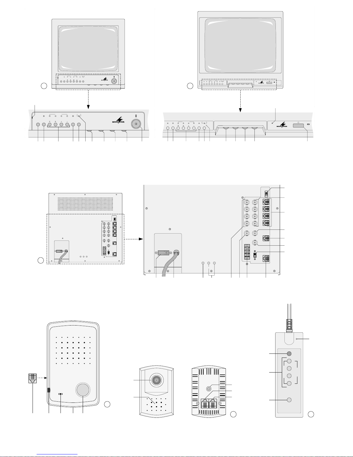
1 Übersicht der Bedienelemente und
Anschlüsse
1.1 Frontseite des Monitors
Abb. 1: Modell CDM-1440, Abb. 2: Modell CDM-1740
1 Mikrofon
2 Taste „MENU NEXT“ zum Aufrufen der drei Sei-
ten des Bildschirm-Menüs und zum anschließenden Abspeichern der Menüeinstellungen
3 Taste „Q/A“ zum Umschalten zwischen Quad-
Betrieb und automatischem Umschaltbetrieb
4 Tasten „1–4“ für die Kamerakanäle 1– 4;
die T asten dienen
-
im Quad-Betrieb dazu, das Bild eines Kamerakanals „einzufrieren“ bzw. „aufzutauen“
-
im Umschaltbetrieb dazu, das Bild eines Kamerakanals als Vollbild dauerhaft auf dem
Bildschirm darzustellen
-
bei aufgerufenem Bildschirm-Menü zum Durchführen der Menüeinstellungen (siehe Kap. 7)
5 Taste „VCR“ zum Ein-/Ausschalten des Recor-
der-Wiedergabebetriebs
6 Taste „TALK“ für die Audiofunktionen (Kap. 5.4)
a Die Taste dient im Quad-Betrieb zum Anwäh-
len desjenigen Kamerakanals, dessen Audiofunktionen aktiviert werden sollen: Die Taste
„TALK“ gedrückt halten, und die entsprechende Taste „1–4“ (4) für den Kamerakanal
drücken (für den gewählten Kanal blinkt die
Einblendung „A“).
b Sind für einen Kamerakanal die Audiofunktio-
nen aktiviert (bei Vollbilddarstellung des Kanals bzw. wenn im Quad-Betrieb „A“ im Bild
des Kamerakanals aufblinkt), ermöglicht die
Taste die Tonübertragung zur Gegensprechanlage TV-40LS, die an diesem Kanal angeschlossen ist: Die Taste „TALK“ während des
Sprechens in das Mikrofon (1) gedrückt halten.
7 Alarmleuchte „CALL“; blinkt bei Alarmauslösung
über einen angeschlossenen Alarmmelder oder
über die Ruftaste (32) der Gegensprechanlage
8 Lautstärkeregler „VOLUME“
9 Regler „H-HOLD“ für die Zeilensynchronisation
10 Helligkeitsregler „BRIGHT“
11 Kontrastregler „CONTRAST“
12 Ein-/Ausschalter für den Bildschirm
1.2 Rückseite des Monitors
Abb. 3: Modell CDM-1440 (Anschlüsse und Bedienelemente des Modells CDM-1740 sind identisch)
13 Schalter „BELL“ zum Aktivieren/Deaktivieren
des Summers
14 BNC-Videoeingänge „IN 1–4“ zum Anschluß
von bis zu vier Kameras mit BNC-Videoausgang
15 6polige Westernbuchsen „CA1 – CA4“ zum An-
schluß von bis zu vier Kameras TVCCD-40
16 BNC-Videoeingang „VCR IN“ für die Videorecor-
der-Wiedergabe: Anschluß an den Video-Wiedergabeausgang des Recorders
17 6polige Westernbuchse „VCR“ für den Anschluß
eines Videorecorders zur Aufzeichnung und Wiedergabe von Ton und Bild; zur Kontaktbelegung
der Buchse siehe Kap. 4.3.3
18 BNC-Videoausgang „QUAD“ für den Anschluß
eines zweiten Monitors bzw. Videorecorders zur
Darstellung oder Aufzeichnung der Kamerabilder
nur im Quad-Betrieb
Please unfold page 3. Then you can always see the
operating elements and connections described.
Contents
1 Operating Elements and Connections . . 4
1.1 Front panel of the monitor . . . . . . . . . . . . . . 4
1.2 Rear panel of the monitor . . . . . . . . . . . . . . 4
1.3 Two-way intercom system TV-40LS . . . . . . 5
1.4 Camera TVCCD-40 . . . . . . . . . . . . . . . . . . . 5
1.5 Remote control TV-40RM . . . . . . . . . . . . . . 5
2 Safety Notes . . . . . . . . . . . . . . . . . . . . . . . 5
3 Applications . . . . . . . . . . . . . . . . . . . . . . . . 6
4 Installation . . . . . . . . . . . . . . . . . . . . . . . . . 6
4.1 Switching off the microphone of
camera TVCCD-40 . . . . . . . . . . . . . . . . . . . 6
4.2 Setting up or assembling the units . . . . . . . 6
4.3 Connections . . . . . . . . . . . . . . . . . . . . . . . . 6
4.3.1 Cameras . . . . . . . . . . . . . . . . . . . . . . . . . . 7
4.3.2 Two-way intercom systems . . . . . . . . . . . 7
4.3.3 Video recorders and additional monitors . 7
4.3.4 Alarm connections . . . . . . . . . . . . . . . . . . 7
4.3.5 Remote control and power supply . . . . . . 7
5 Operation . . . . . . . . . . . . . . . . . . . . . . . . . . 7
5.1 Basic adjustments on the monitor . . . . . . . . 8
5.2 Video monitoring . . . . . . . . . . . . . . . . . . . . . 8
5.2.1 Quad mode . . . . . . . . . . . . . . . . . . . . . . . . 8
5.2.2 Automatic change-over mode . . . . . . . . . . 8
5.2.3 Full screen display of a camera channel . 8
5.3 Reproduction of recordings . . . . . . . . . . . . . 8
5.4 Audio functions . . . . . . . . . . . . . . . . . . . . . . 9
5.4.1 Audio monitoring . . . . . . . . . . . . . . . . . . . . 9
5.4.2 Operation of the two-way intercom system 9
6 Alarm Functions . . . . . . . . . . . . . . . . . . . . 9
7 Programming the Monitor . . . . . . . . . . . 10
7.1 Menu page 1: Setting the date and the time 10
7.2 Menu page 2: Setting the dwell time
of the pictures and the alarm duration . . . . 10
7.3 Menu page 3: Defining the camera titles . . 11
8 Specifications . . . . . . . . . . . . . . . . . . . . . 11
1 Operating Elements and Connections
1.1 Front panel of the monitor
Fig. 1: Model CDM-1440, Fig. 2: Model CDM-1740
1 Microphone
2 Button “MENU NEXT” for calling the three pages
of the screen menu and for subsequent storage
of the menu settings
3 Button “Q /A” for switching from quad mode to
automatic change-over mode and vice versa
4 Buttons “1 to 4” for the camera channels 1 to 4;
the buttons have the following functions:
-
in quad mode: to “freeze” or to “unfreeze” the
picture of a camera channel
-
in change-over mode: to display the picture of
a camera channel permanently on the screen
as full screen picture
-
with the screen menu called: to carry out the
menu settings (see chap. 7)
5 Button “VCR” for switching on and off video
recorder reproduction
6 Button “TALK” for the audio functions (chap. 5.4)
a In quad mode, the button serves for selecting
the camera channel of which the audio functions are to be activated: Keep the button
“TALK” pressed and press the corresponding
button “1 to 4” (4) for the camera channel (a
flashing “A” will appear for the selected channel)
b If the audio functions for a camera channel are
activated (in case of full screen display of the
channel or in case of “A” flashing in the picture
of the camera channel in quad mode), the button allows the sound transmission to the twoway intercom system TV-40LS connected to
this channel: Keep the button “TALK” pressed
while speaking into the microphone (1).
7 Alarm LED “CALL”; flashes in case of an alarm
triggered via a connected alarm device or via the
call button (32) of the two-way intercom system
8 Volume control
9 Control “H-HOLD” for horizontal synchronization
10 Brightness control “BRIGHT”
11 Contrast control
12 Power switch for the screen
1.2 Rear panel of the monitor
Fig. 3: Model CDM-1440 (connections and operating
elements of model CDM-1740 are identical)
13 “BELL” switch to activate/deactivate the buzzer
14 BNC video inputs “IN 1 to 4” to connect up to four
cameras with BNC video output
15 6-pole western jacks “CA1 to CA4” to connect up
to four cameras TVCCD-40
16 BNC video input “VCR IN” for video recorder
reproduction: connection to the recorder’s video
reproduction output
17 6-pole western jack “VCR” to connect a video
recorder for recording and reproducing sound
and picture; for pin configuration of the jack see
chap. 4.3.3
18 BNC video output “QUAD” to connect a second
monitor or a video recorder for displaying or
recording the camera pictures in quad mode only
19 Switch “R –F” to synchronize the cameras in
automatic change-over mode
Position “ON” no vertical rolling of the picture
at the moment of change-over
between the cameras;
but: instable quad picture at the
output “QUAD” (18)
4
GB
D
A
CH
Page 5

19 Schalter „R–F“ zum Synchronisieren der Kame-
ras im automatischen Umschaltbetrieb
Position „ON“ kein vertikaler Bilddurchlauf im
Moment des Umschaltens zwischen den Kameras;
aber: instabiles Quad-Bild am
Ausgang „QUAD“ (18)
Position „OFF“ stabiles Quad-Bild am Ausgang
„QUAD“ (18);
aber: vertikaler Bilddurchlauf im
Moment des Umschaltens zwischen den Kameras
20 Netzschalter „MAIN POWER“ zum Ein-/Aus-
schalten des Gerätes
21 Netzkabel für den Anschluß an 230V~/50Hz
22 Regler „V-HOLD“ für die Bildsynchronisation
(Bei Modell CDM-1440 ist der Regler als versenktes Trimmpotentiometer ausgeführt und darf
nur von qualifiziertem Fachpersonal verstellt werden.)
23 Trimmpotentiometer „V-LIN.“ (für die vertikale
Linearität) und „V-HEG.“ (für die Bildhöhe); nur
für den Service in einer Fachwerkstatt bestimmt
24 BNC-Videoausgänge „OUT 1 – 4“ zum Heraus-
führen der durchgeschleiften Videoeingangssignale der angeschlossenen Kameras: Anschluß
von zusätzlichen Monitoren, Videorecordern etc.
25 BNC-Videoausgang „VCR OUT“ für die Video-
recorder-Aufzeichnung: Anschluß an den VideoAufnahmeeingang des Recorders
26 Alarmausgang „ALARM OUT“ (Relais mit NO-
und NC-Kontakt) zum Aktivieren angeschlossener Geräte (z.B. Videorecorder, Alarmgeber) im
Alarmfall
27 8polige Western-Buchse „REMOCON“ zum An-
schluß der Fernbedienung TV-40RM
1.3 Gegensprechanlage TV-40LS (Abb. 4)
28 6polige Westernbuchse zum Anschluß an die
Kamera TVCCD-40
29 Lautstärkeregler
30 Mikrofon
31 Verbindungsschraube der beiden Gehäuseteile
32 Ruftaste zum Schalten des Monitors auf Emp-
fang der Gegensprechanlage:
Bei Drücken der Taste schaltet der Monitor in
den Alarmmodus und damit auf Vollbilddarstellung des Kamerakanals, an dem die Gegensprechanlage angeschlossen ist. Damit sind die
Audiofunktionen für diesen Kanal aktiviert, die
Tonübermittlung zwischen Monitor und Gegensprechanlage ist jetzt möglich.
1.4 Kamera TVCCD-40 (Abb. 5)
33 Fixfokus-Objektiv
34 Mikrofon
35 Fotogewinde (6,3 mm/
1
/4") zum Montieren der
Kamera auf den Kamerahalter
36 6polige Westernbuchse „MONITOR“ für den An-
schluß der Kamera an eine der Buchsen
„CA1–CA4“ (15) des Monitors
37 6polige Westernbuchse „INTERPHONE“ zum
Anschluß der Gegensprechanlage TV-40LS oder
eines Alarmmelders mit NO-Kontakt (z.B. Bewegungsmelder)
1.5 Fernbedienung TV-40RM (Abb. 6)
Die Bedienelemente der Fernbedienung entsprechen in ihren Funktionen jeweils den Bedienelementen am Monitor (siehe Kap. 1.1).
Ausnahme: Über die Tasten „1–4“ (4) auf der Fernbedienung können keine Programmierungen über
das Bildschirm-Menü (siehe Kap. 7) durchgeführt
werden.
2 Hinweise für den sicheren Gebrauch
Die Geräte (CDM-1440, CDM-1740, TVCCD-40, TV40LS und TV-40RM) entsprechen der Richtlinie für
elektromagnetische Verträglichkeit 89/336/EWG. Die
Monitore CDM-1440 und CDM-1740 entsprechen zusätzlich der Niederspannungsrichtlinie 73/23/EWG.
Der Monitor wird mit lebensgefährlicher Netzspannung (230 V~) versorgt. Nehmen Sie deshalb nie
selbst Eingriffe in diesem Gerät vor. Durch unsachgemäßes Vorgehen besteht die Gefahr eines elektrischen Schlages. Werden der Monitor, die Gegensprechanlage oder die Fernbedienung geöffnet,
erlischt jeglicher Garantieanspruch.
Beachten Sie auch unbedingt die folgenden Punkte:
●
Vorsicht! Die Bildröhre des Monitors ist luftleer.
Bei mechanischer Beschädigung besteht Implosionsgefahr und Verletzungsgefahr durch herumfliegende Glassplitter.
●
Verwenden Sie die Geräte nur im Innenbereich,
und schützen Sie sie vor Feuchtigkeit und Hitze
[zulässiger Einsatztemperaturbereich: von 0°C
bis +35°C (Monitor) bzw. +40°C (übrige Geräte)].
●
Die im Monitor und in der Kamera entstehende
Wärme muß durch Luftzirkulation abgegeben werden. Decken Sie darum die Lüftungslöcher des Gehäuses nicht mit irgendwelchen Gegenständen ab.
●
Stecken Sie nichts durch die Lüftungslöcher des
Monitor- bzw. Kameragehäuses! Dabei kann es zu
einem elektrischen Schlag kommen.
●
Achten Sie darauf, daß die Kabel der Überwachungsanlage keiner starken mechanischen Belastung ausgesetzt werden. Heftiges Ziehen, Knikken oder Verdrehen kann zu Beschädigungen an
den Kabeln und ihren Anschlüssen führen.
●
Nehmen Sie den Monitor nicht in Betrieb bzw. ziehen Sie sofort den Netzstecker aus der Steckdose, wenn:
1. sichtbare Schäden am Monitor , an seiner Netzanschlußleitung oder an den angeschlossenen
Geräten vorhanden sind,
2. nach einem Sturz oder ähnlichem der V erdacht
auf einen Defekt besteht,
Position “OFF” stable quad picture at the output
“QUAD” (18);
but: vertical rolling of the picture
at the moment of change-over
between the cameras
20 Mains switch “MAIN POWER” for switching on
and off the unit
21 Mains cable for connection to 230V~/50Hz
22 Control “V-HOLD” for vertical synchronization
(In case of model CDM-1440, the control is provided as a recessed trimming potentiometer to
be adjusted by skilled personnel only.)
23 Trimming potentiometers “V-LIN.” (for vertical
linearity) and “V-HEG.” (for picture height); provided for service by skilled personnel only
24 BNC video outputs “OUT 1 to 4” to route out the
fed-through video input signals of the connected
cameras: connection of additional monitors, video
recorders, etc.
25 BNC video output “VCR OUT” for recordings by
a video recorder: connection to the recorder’s
video recording input
26 Alarm output “ALARM OUT” (relay with NO and
NC contact) to activate connected units (e. g.
video recorder, alarm devices) in case of alarm
27 8-pole western jack “REMOCON” to connect the
remote control TV-40RM
1.3 Two-way intercom system TV-40LS (Fig. 4)
28 6-pole western jack to connect the camera
TVCCD-40
29 Volume control
30 Microphone
31 Connecting screw of the two housing parts
32 Call button to switch the monitor to reception of
the two-way intercom system:
When the button is pressed, the monitor switches
to alarm mode and thus to full screen display of
the camera channel to which the two-way intercom system is connected. This activates the
audio functions of this channel, and then allows
sound transmission between the monitor and the
two-way intercom system.
1.4 Camera TVCCD-40 (Fig. 5)
33 Fixfocus lens
34 Microphone
35 Thread (6.3mm/
1
/
4") to mount the camera on the
camera holder
36 6-pole western jack “MONITOR” to connect the
camera to one of the jacks “CA1 to CA4” (15) of
the monitor
37 6-pole western jack “INTERPHONE” to connect
the two-way intercom system TV-40LS or an
alarm device with NO contact (e. g. motion detector)
1.5 Remote control TV-40RM (Fig. 6)
The functions of the operating elements on the
remote control correspond to those of the operating
elements on the monitor (see chap. 1.1).
Exception: The buttons “1 to 4” (4) on the remote
control do not allow programming via the screen
menu (see chap. 7).
2 Safety Notes
The units (CDM-1440, CDM-1740, TVCCD-40, TV40LS, and TV-40RM) correspond to the directive
for electromagnetic compatibility 89/336/EEC. The
monitors CDM-1440 and CDM-1740 additionally
correspond to the low voltage directive 73/23/EEC.
The monitor is supplied with hazardous mains voltage (230V~). Leave servicing to skilled personnel
only. Inexpert handling may cause an electric
shock hazard. Furthermore, any guarantee claim
will expire if the monitor, the two-way intercom system, or the remote control have been opened.
Please observe the following items in any case:
●
Caution! The picture tube of the monitor is vacuous. In case of mechanical damage, there is an
implosion hazard and scattered glass may cause
injuries.
●
The units are suitable for indoor use only. Protect
them against humidity and heat [admissible
ambient temperature range: from 0 °C to +35 °C
(monitor) or +40°C (other units)].
●
The heat generated within the monitor and the
camera must be carried off by air circulation.
Therefore, do not cover the air vents of the housing with any objects.
●
Do not insert anything through the air vents of the
monitor housing or the camera housing! An electric shock may result.
●
T ake care that the cables of the monitoring system
are not subjected to severe mechanical stress.
Intense tearing, buckling, or twisting may result in
damage to the cables and their connections.
●
Do not operate the monitor or immediately disconnect the plug from the mains socket
1. if there is visible damage to the monitor, to its
mains cable or to the connected units,
2. if a defect might have occurred after a unit was
dropped or suffered a similar accident,
3. if malfunctions occur.
In any case the units must be repaired by skilled
personnel.
●
A damaged mains cable of the monitor must be
replaced by the manufacturer or by skilled personnel only.
●
Never pull the mains cable of the monitor to disconnect the mains plug from the socket.
●
For cleaning only use a dry, soft cloth, by no
means chemicals or water.
●
If the units are used for other purposes than originally intended, if they are not connected or operated in the correct way or not repaired by skilled
personnel, no liability for any damage will be
accepted.
●
If the units are to be put out of operation permanently, take them to a local recycling plant for disposal.
5
GB
D
A
CH
Page 6
3. Funktionsstörungen auftreten.
Geben Sie die Geräte in jedem Fall zur Reparatur
in eine Fachwerkstatt.
●
Eine beschädigte Netzanschlußleitung des Monitors darf nur durch den Hersteller oder durch eine
autorisierte Fachwerkstatt ersetzt werden.
●
Ziehen Sie den Netzstecker des Monitors nie an
der Zuleitung aus der Steckdose.
●
Verwenden Sie für die Reinigung nur ein trockenes, weiches Tuch, auf keinen Fall Chemikalien
oder Wasser.
●
Werden die Geräte zweckentfremdet, falsch angeschlossen, nicht richtig bedient oder nicht fachgerecht repariert, kann für eventuelle Schäden
keine Haftung übernommen werden.
●
Sollen die Geräte endgültig aus dem Betrieb genommen werden, übergeben Sie sie zur Entsorgung einem örtlichen Recyclingbetrieb.
3 Einsatzmöglichkeiten
Der Monitor CDM-1440 bzw. CDM-1740 sowie seine
Zubehörgeräte TVCCD-40, TV-40LS und TV-40RM
sind für den Einsatz in Videoüberwachungsanlagen
konzipiert.
Bei dem Gerät CDM-1440 bzw. CDM-1740 handelt es sich um einen S/ W-Monitor mit integriertem
Quad-Prozessor. Die Bedienung des Monitors kann
direkt über die Bedienelemente am Gerät oder über
die Fernbedienung TV-40RM erfolgen.
Der Quad-Prozessor des Gerätes ermöglicht die
Darstellung von bis zu vier Kamerabildern:
1. zusammen als verkleinerte Bilder auf dem in vier
Segmente unterteilten Bildschirm im Quad-
Betrieb
2. als Vollbilder, entweder ständig als Dauerbild ei-
nes Kamerakanals oder nacheinander im auto-
matischen Umschaltbetrieb
Der Lautsprecher und das eingebaute Mikrofon des
Monitors erlauben sowohl eine Audioüberwachung
am Kamerastandort als auch den Betrieb mit der
Gegensprechanlage TV-40LS. Außerdem bietet das
Gerät die Möglichkeit, zusätzliche Überwachungsgeräte, wie z. B. einen zweiten Monitor oder einen
Videorecorder zur Aufzeichnung und Wiedergabe
der Kamerabilder, anzuschließen. Für jeden der vier
Kamerakanäle ist ein NO-Alarmeingang vorhanden.
Bei Alarmauslösung über einen dieser Eingänge
schaltet das Gerät auf Vollbilddarstellung des betreffenden Kanals, und es erfolgt eine optische und
akustische Alarmmeldung. Zusätzlich schaltet ein
Alarmrelais (NO / NC-Kontakt) und kann somit z. B
einen angeschlossenen Videorecorder starten oder
weitere Signalelemente aktivieren.
Für den Anschluß an den Monitor CDM-1440 bzw .
CDM-1740 eignen sich speziell die S/ W-Kameras
TVCCD-40 mit Fixfokus-Objektiv und eingebautem
Mikrofon (ausschaltbar). Es ist jedoch auch möglich,
Kameras eines anderen Typs zu verwenden.
4 Installation
Die Installation aller Komponenten der Überwachungsanlage sollte nur von qualifiziertem Fachpersonal durchgeführt werden.
4.1 Mikrofon der Kamera TVCCD-40
abschalten
Das Mikrofon der Kamera TVCCD-40 kann bei
Bedarf ausgeschaltet werden. Die in Kap. 5.4.1
beschriebene Audioüberwachung ist dann nicht
mehr möglich. Die Gegensprechanlage TV-40LS
kann jedoch auch bei ausgeschaltetem Kameramikrofon betrieben werden.
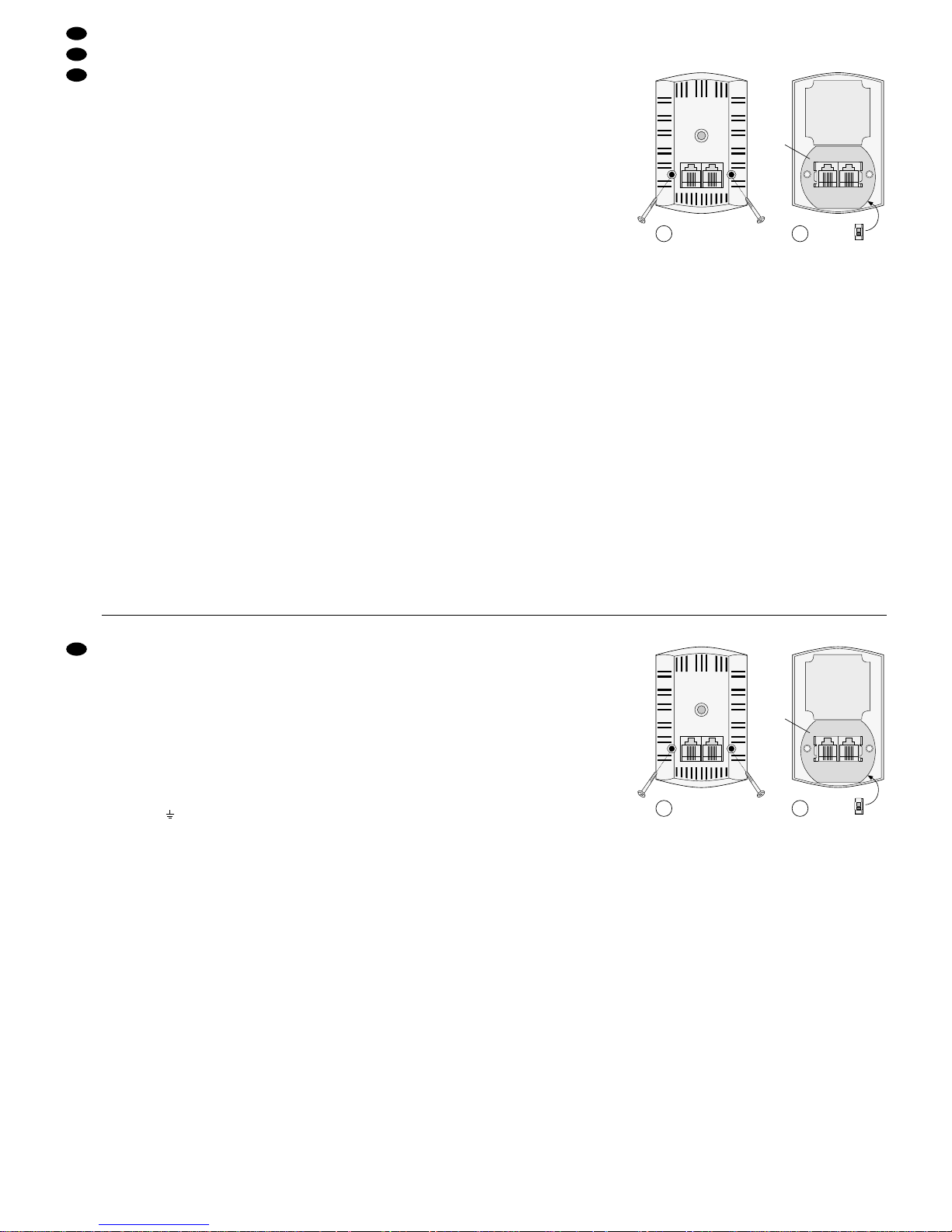
1) Die beiden Schrauben auf der Kamerarückseite
lösen (siehe Abb. 7), und die Rückseite nach oben
wegklappen (Vorsicht, nicht die Kabel abreißen!).
2) Die untere Leiterplatte [(a) in Abb. 8] vorsichtig
aus dem Gehäuse herausheben und leicht her-
umdrehen, so daß der Schalter „SW101“ auf der
Rückseite der Leiterplatte zugänglich ist.
3) Den Schalter „SW101“ auf Position „OFF“ stellen
(siehe Abb. 8). Das Mikrofon ist jetzt ausgeschal-
tet.
4) Die Leiterplatte in ihre Ausgangslage zurücksetzen, und die Kamerarückseite wieder auflegen
und mit den beiden Schrauben befestigen.
4.2 Aufstellung bzw. Montage der Geräte
1) Den Monitor CDM-1440 bzw. CDM-1740 am gewünschten Standort aufstellen. Zur Vermeidung
von Wärmestaus muß der Stellplatz des Monitors
so gewählt werden, daß bei Betrieb eine ausreichende Luftzirkulation gewährleistet ist.
2) Die Kamera TVCCD-40 über ihre Gewindebohrung (35) auf den beiliegenden Kamerahalter oder
auf eine andere Kamerahalterung mit Fotogewinde (6,3mm/
1
/4") aufschrauben.
Bei Verwendung des beiliegenden Halters diesen mit drei Schrauben an der gewünschten
Stelle anbringen. Zum Ausrichten der Kamera auf
den Überwachungsbereich die Feststellschraube
am Halter lösen, die Kamera in die gewünschte
Positon bringen und durch Anziehen der Feststellschraube arretieren. Beim Ausrichten der Kamera
darauf achten, daß das Objektiv nicht direkter
Sonneneinstrahlung ausgesetzt ist.
3) Um die Gegensprechanlage TV-40LS zu montieren, die Schraube (31) lösen. Die rückseitige
Gehäuseschale abnehmen und über die beiden
Montagebohrungen an der Wand befestigen.
Nach dem Verlegen des Anschlußkabels das vordere Gehäuseteil auf die Gehäuseschale setzen,
a
SW101
ON
OFF
MONITOR INTERPHONE
●
Important for U.K. Customers!
The wires in the mains lead of the monitor are
coloured in accordance with the following code:
green/yellow = earth,
blue = neutral
brown = live
As the colours of the wires in the mains lead of this
appliance may not correspond with the coloured
markings identifying the terminals in your plug,
proceed as follows:
1. The wire which is coloured green and yellow
must be connected to the terminal in the plug
which is marked with the letter E or by the earth
symbol , or coloured green or green and
yellow.
2. The wire which is coloured blue must be connected to the terminal which is marked with the
letter N or coloured black.
3. The wire which is coloured brownmust be connected to the terminal which is marked with the
letter L or coloured red.
Warning
-
This appliance must be earthed.
3 Applications
The monitor CDM-1440 (or CDM-1740) and its accessory units TVCCD-40, TV-40LS, and TV-40RM
have been designed for use in video monitoring systems.
CDM-1440 (or CDM-1740) is a B/W monitor with
integrated quad processor. The monitor can be operated directly via the operating elements on the unit
or via the remote control TV-40RM.
The quad processor of the unit allows the display
of up to four camera pictures:
1. together as reduced pictures on the screen di-
vided into four segments in quad mode
2. as full screen pictures, either continuously as
permanent picture of a camera channel or suc-
cessively in automatic change-over mode
The speaker and the integrated microphone of the
monitor allow both an audio monitoring at the camera
location and an operation with the two-way intercom
system TV-40LS. Furthermore, the unit permits
connection of additional monitoring units, e.g. a second monitor or a video recorder for recording and
reproducing the camera pictures. An NO alarm input
is provided for each of the four camera channels. If
an alarm is triggered via one of these inputs, the unit
switches to full screen display of the corresponding
channel and both a visible and an audible alarm signal is triggered. Additional switching of an alarm relay
(NO/ NC contact) allows e. g. to start a connected
video recorder or to activate further signal elements.
The B/W cameras TVCCD-40 with fixfocus lens
and integrated microphone (can be switched off) are
particularly suitable for connecting to the monitor
CDM-1440 (or CDM-1740). However, it is also possible to use cameras of a different type.
4 Installation
Installation of all components of the monitoring system should be performed by skilled personnel only.
4.1 Switching off the microphone of camera
TVCCD-40
The microphone of camera TVCCD-40 can be
switched off, if required. In this case, the audio
monitoring described in chap. 5.4.1 is no longer possible. However, the two-way intercom system TV40LS can be operated even with the camera microphone switched off.
1) Unscrew the two screws on the rear side of the
camera (see fig. 7) and fold the rear side
upwards (Caution: Do not tear off the cables!).
2) Carefully remove the lower PCB [(a) in fig. 8)]
from the housing and slightly turn it around so
that the switch “SW101” on the rear side of the
PCB is accessible.
3) Set the switch “SW101” to the position “OFF”
(see fig. 8). The microphone is now switched off.
4) Put the PCB back to its initial position, replace
the rear side of the camera and fasten it with the
two screws.
4.2 Setting up or assembling the units
1) Set up the monitor CDM-1440 (or CDM-1740) at
the desired location. To avoid heat accumulation,
the location of the monitor must allow a sufficient
air circulation during operation.
2) Screw the camera TVCCD-40 via its threaded
hole (35) onto the supplied camera holder or another camera holder with thread 6.3mm/
1
/4".
If the supplied holder is used, mount it to the
desired location by means of three screws. To
align the camera to the monitoring area, release
the setscrew on the holder, set the camera to the
desired position and lock it by tightening the setscrew. When aligning the camera, take care that
the lens is not exposed to direct sunlight.
3) To mount the two-way intercom system TV-40LS,
release the screw (31). Remove the rear housing
shell and fix it to the wall by means of the two
mounting holes. After laying the connecting cable,
place the front part of the housing on the housing
shell until it locks into place and tighten the
connecting screw to join the two parts.
4.3 Connections
●
Prior to connecting units or to changing existing
connections, always switch off the monitor with
the mains switch “MAIN POWER” (20).
a
SW101
ON
OFF
MONITOR INTERPHONE
6
GB
D
A
CH
7
8
7 8
Page 7
so daß es einrastet, und die beiden Teile mit der
Verbindungsschraube wieder verschrauben.
4.3 Anschlüsse
●
Schalten Sie vor dem Anschließen von Geräten
bzw. vor dem Ändern bestehender Anschlüsse
den Monitor immer mit dem Netzschalter „MAIN
POWER“ (20) aus.
●
Verwenden Sie keine Telefonanschlußkabel, um
die Kabel der Überwachungsanlage zu verlängern. Der Monitor und/oder die Kameras könnten
beschädigt werden.
4.3.1 Kameras
Der Monitor besitzt vier Kamerakanäle zum Anschluß von bis zu vier Kameras. Pro Kanal immer
nur eine Kamera anschließen, entweder an die We-
stern-Buchse oder an die BNC-Buchse des Kanals.
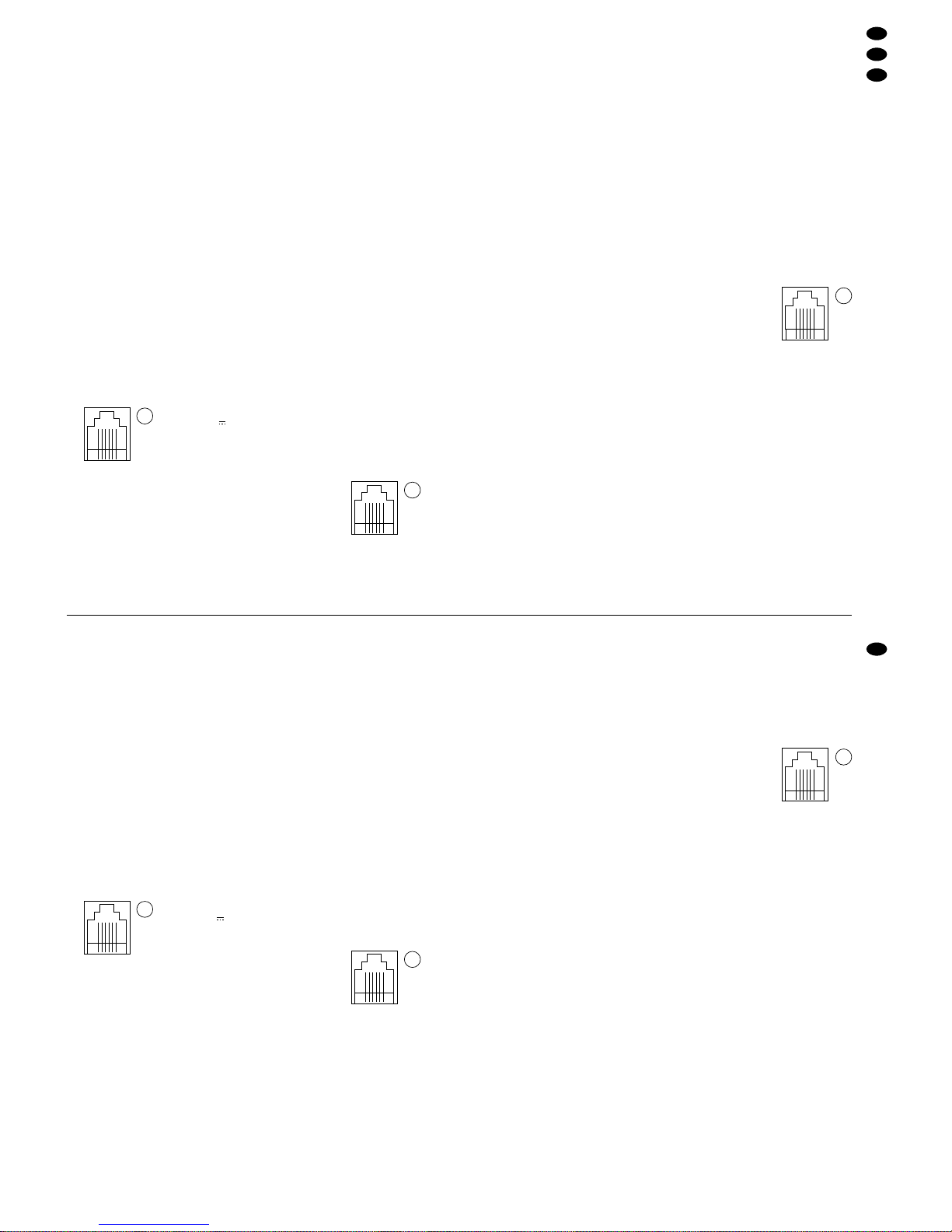
1) Zum Anschluß einer Kamera TVCCD-40 das der
Kamera beiliegende Kabel in die Buchse „MONITOR“ (36) stecken, und die Kamera über das
Kabel mit einer der Western-Buchsen „CA1–CA4“
(15) verbinden.
Über diese Buchse laufen alle Audio- und Videoverbindungen zwischen Monitor und Kamera
(und eventuell angeschlossener Gegensprechanlage TV-40LS) sowie mögliche Alarmverbindungen und die Stromversorgung der Kamera
(siehe Kontaktbelegung der Buchse in Abb. 9).
Pin 1 = Klingel-/Alarmimpuls
Pin 2 = 15V
Pin 3 = Audiosignal vom Monitor
Pin 4 = Videosignal
Pin 5 = Audiosignal von der Kamera
Pin 6 = Masse
Bei Bedarf kann das Anschlußkabel mit dem
Kabel TV-20CW und dem Adapter TV-40AW von
MONACOR verlängert werden.
2) Kameras mit BNC-Videoausgang an die BNCBuchsen „IN 1 –4“ (14) anschließen. Über die
BNC-Buchse erhält der Monitor nur das Videosignal der Kamera.
Sollen auch die Audio- und Alarmfunktionen
des Kamerakanals genutzt werden (z.B. bei Instal-
lation eines Mikrofons oder Alarmmelders am Kamerastandort), empfiehlt es sich, die Kamera über
den Adapter TV-40JB und das Kabel TV-20CW
von MONACOR an die entsprechende WesternBuchse des Kanals anzuschließen. In diesem Fall
den Videoausgang der Kamera mit der BNCBuchse des Adapters verbinden und die Audiound Alarmverbindungen über die Klemmanschlüsse durchführen.
4.3.2 Gegensprechanlagen
An je eine Kamera TVCCD-40 kann eine Gegensprechanlage TV-40LS angeschlossen werden. Dazu das der Gegensprechanlage beiliegende Anschlußkabel in die rückseitige Buchse (28) stecken,
und die Gegensprechanlage über das Kabel mit der
Buchse „INTERPHONE“ (37) der Kamera verbinden.
4.3.3 Videorecorder und zusätzliche Monitore
1) Zur Aufzeichnung und anschließender Wiedergabe kann ein Videorecorder wahlweise entweder über die beiden BNC-Buchsen „VCR OUT“
(25) und „VCR IN“ (16) oder über die WesternBuchse „VCR“ (17) angeschlossen werden.
Über die BNC-Buchsen wird nur das Videosignal übertragen. Bei Verwendung der BNCBuchsen den Video-Aufnahmeeingang des
Recorders an die Buchse „VCR OUT“ und den
Video-Wiedergabeausgang des Recorders an
die Buchse „VCR IN“ anschließen.
Über die Westernbuchse „VCR“ ist die Aufzeichnung und Wiedergabe der Video- und Audiosignale möglich. Die Ein- und Ausgänge für Video
und Audio am Recorder über entsprechende
Adapter mit der Buchse verbinden. Zur Kontaktbelegung der Buchse siehe Abb. 10.
Pin 1 = Masse
Pin 2 = Audioausgang
Pin 3 = Videoausgang
Pin 4 = Audioeingang
Pin 5 = Videoeingang
Pin 6 = Masse
2) Ein weiterer Monitor oder ein Videorecorder zur
Aufzeichnung kann an die BNC-Buchse „QUAD“
(18) angeschlossen werden. An diesem Ausgang
wird immer das Quad-Bild herausgeführt, unabhängig vom eingestellten Betriebsmodus am Gerät CDM-1440 bzw. CDM-1740.
Das Quad-Bild an diesem Ausgang erscheint
ohne Einblendungen (wie z. B. Datum, Uhrzeit,
Kameratitel etc.).
3) An den BNC-Buchsen „OUT 1 – 4“ (24) werden
die durchgeschleiften Videosignale der Kameraeingänge herausgeführt. Hier lassen sich weitere
Monitore oder Videorecorder anschließen.
Wichtig! Keine unbenutzten Kabel in den Ausgangsbuchsen „OUT 1 – 4“ stecken lassen, weil
dann die automatische Impedanzumschaltung
(75Ω/ hochohmig) für die Kameraeingangsbuchsen nicht korrekt arbeitet.
4.3.4 Alarmverbindungen
1) Es besteht die Möglichkeit, pro Kamerakanal des
Monitors einen Alarmmelder mit NO-Kontakt (z.B.
Bewegungsmelder) anzuschließen:
Bei Verwendung der Kamera
TVCCD-40 den Alarmmelder an
Pin 1 (Alarmimpuls) und Pin 6
(Masse) der Buchse „INTERPHONE“ (37) anschließen (siehe Abb. 11).
Wird bei Verwendung einer Kamera mit BNCBuchse der Adapter TV-40JB von MONACOR
genutzt (siehe Kap. 4.3.1, Punkt 2), den Melder
an die Alarm-Klemmanschlüsse des Adapters anschließen (siehe Kontaktbelegung des Adapters).
2) Der Alarmausgang „ALARM OUT“ (26) ist ein
Relais mit NO- und NC-Kontakt, das bei Alarmauslösung schaltet und somit angeschlossene
Geräte aktiviert. Der Alarmausgang kann z.B. an
den Alarmeingang des Videorecorders angeschlossen werden – um die Aufnahme zu starten
bzw. den Recorder im Alarmfall von Timelapseauf Echtzeit-Aufnahme zu schalten – oder mit
weiteren Alarmgebern verbunden werden.
4.3.5 Fernbedienung und Stromversorgung
Die Fernbedienung TV-40RM für den Monitor an die
Western-Buchse „REMOCON“ (27) anschließen.
1
6
1
6
●
Do not use telephone connection cables to extend
the cables of the monitoring system. The monitor
and/or the cameras might be damaged.
4.3.1 Cameras
The monitor has four camera channels for connecting up to four cameras. Connect one camera only
per channel, either to the western jack or to the BNC
jack of the channel.
1) To connect a camera TVCCD-40, connect the
cable supplied with the camera to the jack “MONITOR” (36), and connect the camera to one of the
western jacks “CA1 to CA4” (15) via the cable.
All audio and video connections between the
monitor and the camera (and the two-way intercom system TV-40LS that may be connected) as
well as any possible alarm connections and the
power supply of the camera are made via this
jack (see pin configuration of the jack in fig. 9).
Pin 1 = bell/alarm pulse
Pin 2 = 15V
Pin 3 = audio signal from the monitor
Pin 4 = video signal
Pin 5 = audio signal from the camera
Pin 6 = ground
If required, the connecting cable can be extended
with the cable TV-20CW and the adapter TV40AW by MONACOR.
2) Connect cameras with BNC video output to the
BNC jacks “IN 1 to 4” (14). Via the BNC jack, the
monitor only receives the video signal of the camera.
If the audio and alarm functions of the camera
channel are to be used as well (e. g. in case of
installation of a microphone or an alarm device at
the camera location), it is recommeded to connect the camera to the corresponding western
jack of the channel via the adapter TV-40JB and
the cable TV-20CW by MONACOR. In this case,
connect the video output of the camera to the
BNC jack of the adapter and make the audio and
alarm connections via the terminals.
4.3.2 Two-way intercom systems
A two-way intercom system TV-40LS can be
connected to a camera TVCCD-40 each. For this
purpose, connect the cable supplied with the twoway intercom system to the rear jack (28) and
connect the two-way intercom system to the jack
“INTERPHONE” (37) of the camera via the cable.
4.3.3 Video recorders and additional monitors
1) For recording and subsequent reproduction, a
video recorder can be connected either via the
two BNC jacks “VCR OUT” (25) and “VCR IN”
(16) or via the western jack “VCR” (17).
Via the BNC jacks, only the video signal is
transmitted. When using the BNC jacks, connect
the video recording input of the recorder to the
jack “VCR OUT”, and the video reproduction output of the recorder to the jack “VCR IN”.
Recording and reproduction of the video and
audio signals is possible via the western jack
“VCR”. Connect the video and audio inputs and
outputs on the recorder to the jack via corresponding adapters. For pin configuration of the jack see
fig. 10.
Pin 1 = ground
Pin 2 = audio output
Pin 3 = video output
Pin 4 = audio input
Pin 5 = video input
Pin 6 = ground
2) A further monitor or a video recorder for recording
can be connected to the BNC jack “QUAD” (18).
The quad picture is always routed out at this output, independent of the operating mode adjusted
on the unit CDM-1440 (or CDM-1740).
The quad picture at this output is displayed
without any further information (e. g. date, time,
camera title, etc.).
3) At the BNC jacks “OUT 1 to 4” (24), the fedthrough video signals of the camera inputs are
routed out. Further monitors or video recorders
can be connected there.
Important! Do not leave unused cables in the
output jacks “OUT 1 to 4” as the automatic im-
pedance switching (75 Ω/ high impedance) for
the camera input jacks will not operate correctly
in this case.
4.3.4 Alarm connections
1) It is possible to connect an alarm device with NO
contact (e. g. motion detector) to each camera
channel of the monitor:
In case of camera TVCCD-40,
connect the alarm device to
pin 1 (alarm pulse) and pin 6
(ground) of the jack “INTERPHONE” (37) (see fig. 11).
If the adapter TV-40JB by MONACOR is used for
a camera with BNC jack (see chap. 4.3.1, item 2),
connect the device to the alarm terminals of the
adapter (see pin configuration of the adapter).
2) The alarm output “ALARM OUT” (26) is a relay
with NO and NC contact which responds in case
of alarm triggering and thus activates connected
units. The alarm output can be connected, e.g. to
the alarm input of the video recorder (to start the
recording or to switch the recorder from time
lapse recording to real time recording in case of
alarm) or it can be connected to further alarm
devices.
4.3.5 Remote control and power supply
Connect the remote control TV-40RM for the monitor to the western jack “REMOCON” (27).
After all components of the video monitoring sys-
tem have been connected, connect the plug of the
mains cable (21) to a mains socket (230V~/50Hz).
5 Operation
During initial operation of the monitor, the basic
adjustments programmed by the manufacturer are
activated. Via a screen menu, the unit can be reprogrammed according to your own requirements. For
programming the unit see chap. 7.
The functions of the operating elements on the
remote control TV-40RM (fig. 6) correspond to those
1
6
1
6
7
GB
D
A
CH
9
9
10
10
11
1
6
11
1
6
Page 8
Nach dem Anschluß aller Komponenten der Videoüberwachungsanlage den Stecker des Netzkabels
(21) in eine Netzsteckdose (230V~/50Hz) stecken.
5 Bedienung
Bei der ersten Inbetriebnahme des Monitors sind die
vom Hersteller einprogrammierten Grundeinstellungen aktiviert. Über ein Bildschirm-Menü kann das
Gerät nach eigenen Wünschen neu programmiert
werden. Zum Programmieren des Gerätes siehe
Kap. 7.
Die Bedienelemente der Fernbedienung TV40RM (Abb. 6) entsprechen in ihren Funktionen
jeweils den Bedienelementen (1), (3), (4) und (6) am
Monitor. Folglich können alle Bedienschritte, die
über diese Bedienelemente durchgeführt werden,
wahlweise über den Monitor oder die Fernbedienung laufen.
Ausnahme: Mit den Tasten „1 – 4“ (4) auf der Fernbedienung sind keine Programmierungen über das
Bildschirm-Menü möglich.
5.1 Grundeinstellungen am Monitor
1) Den Monitor mit dem Schalter „MAIN POWER“
(20) auf der Geräterückseite einschalten. Das
Gerät ist jetzt betriebsbereit und befindet sich im
Quad-Betrieb (siehe Kap. 5.2.1)
2) Den Bildschirm mit dem Schalter (12) einschal-
ten. Die Bildschirm-Betriebsanzeige leuchtet,
und nach einigen Sekunden erscheint das Quad-
Bild.
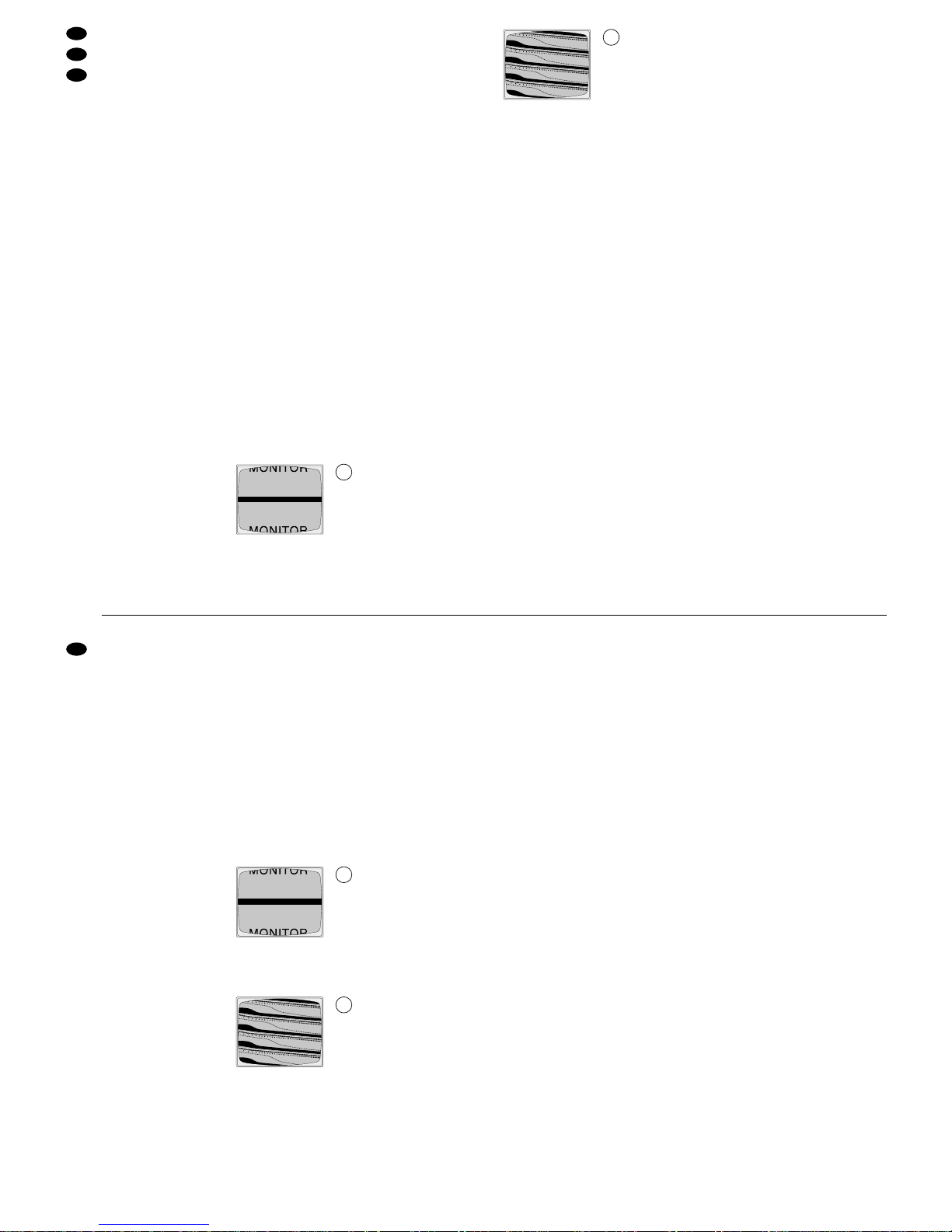
3) Nur für Modell CDM-
1740: Läuft das Bild
durch (Abb. 12), mit
dem Regler „V-HOLD“
(22) ein stabiles Bild
einstellen.
(Bei Modell CDM-1440 ist der Regler „V-HOLD“
als versenktes Trimmpotentiometer ausgeführt
und darf nur von qualifiziertem Fachpersonal ver-
stellt werden.)
4) Wenn die Zeilen nicht
synchronisiert werden
(Abb. 13), das Bild mit
dem Regler „H-HOLD“
(9) stabilisieren.
5) Mit dem Helligkeitsregler „BRIGHT“ (10) und
dem Kontrastregler „CONTRAST“ (11) ein optimales Bild einstellen.
6) Um im automatischen Umschaltbetrieb (siehe
Kap. 5.2.2) ein vertikales Durchlaufen des Bildes
im Moment des Umschaltens zu verhindern, den
Schalter „R–F“ (19) auf Positon „ON“ stellen.
Hinweis! Die Schalterstellung „ON“ beeinflußt
die Stabilität des Quad-Bildes, das am Videoausgang „QUAD“ (18) abgegeben wird: Wenn sich
der Monitor im automatischen Umschaltbetrieb
befindet, kann es im Moment des Umschaltens
zu einem „Hüpfen“ des Quad-Bildes am Ausgang
„QUAD“ kommen. Soll dieser Effekt vermieden
werden, den Schalter „R–F“ auf „OFF“ stellen.
7) Soll keine Live-Videoüberwachung über den Monitor stattfinden, empfiehlt es sich, den Bildschirm
mit dem Schalter (12) abzuschalten (BildschirmBetriebsanzeige erlischt). Dies schont den Bildschirm und erhöht damit die Lebensdauer des
Gerätes. Auf die Videoausgänge hat die Bildschirmabschaltung keinen Einfluß, so werden
z.B. Bildaufzeichnungen über einen angeschlossenen Videorecorder nicht unterbrochen.
Zum Ausschalten des kompletten Geräts (Video-Quad-Prozessor und Bildschirm) den Netzschalter „MAIN POWER“ (20) auf „OFF“ stellen.
5.2 Videoüberwachung
5.2.1 Quad-Betrieb
Mit der Taste „Q/A“ (3) wird zwischen Quad-Betrieb
und automatischem Umschaltbetrieb (siehe Kap.
5.2.2) umgeschaltet. Im Quad-Betrieb wird der Bildschirm des Monitors zur Darstellung von bis zu vier
Kamerabildern gleichzeitig in vier Segmente unterteilt. Sind weniger als vier Kameras angeschlossen,
werden die entsprechenden Segmente auf dem
Monitor dunkelgeschaltet, und es erscheint die Meldung „NO VIDEO“.
Zur Anzeige dieses Betriebsmodus leuchtet die
rote LED über der Taste „Q/A“. Für jeden im QuadModus dargestellten Kameraeingang leuchtet die
grüne LED über der entsprechenden T aste „1–4“ (4).
„Einfrieren“ der Kamerabilder
Zum „Einfrieren“ eines Kamerabildes, d. h. Abspeichern als Standbild, die jeweilige T aste „1– 4“ (4) des
betreffenden Kamerakanals drücken. Die LED über
der T aste blinkt, und für das eingefrorene Kamerabild
wird die Meldung „FROZEN“ eingeblendet. Das eingefrorene Bild wird nur im Quad-Betrieb dargestellt,
und bleibt auch erhalten, wenn zwischendurch in
einen anderen Betriebsmodus umgeschaltet wird.
Soll das Bild wieder „aufgetaut“ werden, im QuadBetrieb die Taste des Kamerakanals erneut drücken.
Hinweis: Bei Unterbrechung der Stromversorgung
und/oder der Videosignalleitung einer Kamera (z.B. bei Manipulationen an der
Überwachungsanlage), wird das zuletzt
vor der Unterbrechung erfaßte Kamerabild in der Quad-Darstellung ebenfalls
„eingefroren“. Zusätzlich blinkt in dem entsprechenden Quadranten die Meldung
„NO VIDEO“.
5.2.2 Automatischer Umschaltbetrieb
Mit der Taste „Q/A“ (3) wird zwischen Quad-Betrieb
(siehe Kap. 5.2.1) und automatischem Umschaltbetrieb umgeschaltet. In diesem Betriebsmodus
werden das Quad-Bild und die Vollbilder aller angeschlossenen Kameras in festgelegten Schaltintervallen nacheinander auf dem Bildschirm dargestellt.
(Zum Festlegen der Schaltintervalle siehe Kap. 7.2.)
Folgende Schaltsequenz wird durchlaufen:
Vollbild Kamera 1
Vollbild Kamera 2
Vollbild Kamera 3
Vollbild Kamera 4
Quad-Darstellung
of the operating elements (1), (3), (4), and (6) on the
monitor. Consequently , all operating steps performed
via these operating elements can be made either via
the monitor or via the remote control.
Exception: The buttons “1 to 4” (4) on the remote
control do not allow programming via the screen
menu.
5.1 Basic adjustments on the monitor
1) Switch on the monitor with the switch “MAIN
POWER” (20) on the rear side of the unit. The
unit is now ready for operation and is in quad
mode (see chap. 5.2.1).
2) Switch on the screen with the switch (12). The
operating LED of the screen lights up and after a
few seconds the quad picture appears.
3) For model CDM-1740
only: If the picture rolls
up or down (fig. 12),
adjust a stable picture
by means of the control “V-HOLD” (22).
(In case of model CDM-1440, the control
“V-HOLD” is provided as a recessed trimming
potentiometer to be adjusted by skilled personnel
only.)
4) If there is no horizontal synchronization
(fig. 13), stabilize the
picture by means of
the control “H-HOLD”
(9).
5) Adjust an optimum picture by means of the
brightness control “BRIGHT” (10) and the “CONTRAST” control (11).
6) To prevent vertical rolling of the picture in automatic change-over mode (see chap. 5.2.2) at the
moment of change-over, set the switch “R –F”
(19) to the position “ON”.
Note! The switch position “ON” affects the
stability of the quad picture delivered to the video
output “QUAD” (18): With the monitor in automatic
change-over mode, at the moment of changeover, “skipping” of the quad picture may result at
the “QUAD” output. To avoid this effect, set the
switch “R–F” to “OFF”.
7) If no live video monitoring via the monitor is required, it is recommeded to switch off the screen
with the switch (12). (Operating LED of the screen
extinguishes.) This will save the screen and thus
increase the life of the unit. Switching off the
screen does not affect the video outputs, e. g.
video recordings via a connected video recorder
are not interrupted.
To switch off the complete unit (video quad
processor and screen), set the mains switch
“MAIN POWER” (20) to “OFF”.
5.2 Video monitoring
5.2.1 Quad mode
The button “Q/A” (3) switches from quad mode to
automatic change-over mode (see chap. 5.2.2) and
vice versa. In quad mode, the screen of the monitor
is divided into four segments to display up to four
camera pictures at the same time. If less than four
cameras are connected, the corresponding segments on the monitor remain dark and the message
“NO VIDEO” appears.
To indicate this operating mode, the red LED
above the button “Q/A” lights up. For each camera
input displayed in the quad mode, the green LED
above the corresponding button “1 to 4” (4) lights up.
“Freezing” of camera pictures
To “freeze” a camera picture, i.e. to store it as a still
picture, press the corresponding button “1 to 4” (4)
of the respective camera channel. The LED above
the button will flash, and the message “FROZEN” is
displayed for the frozen camera picture. The frozen
picture is displayed in quad mode only, and it is
maintained even if a different operating mode was
selected in the meantime. To “unfreeze” the picture,
press the button of the camera channel once again
in quad mode.
Note: In case of interruption of the power supply
and/or the video signal line of a camera (e. g.
in case of tampering actions on the monitoring
system), the last camera picture taken before
the interruption is also “frozen” in quad mode.
In addition, the message “NO VIDEO” is flashing in the corresponding quadrant.
5.2.2 Automatic change-over mode
The button “Q/A” (3) switches from quad mode (see
chap. 5.2.1) to automatic change-over mode and
vice versa. In this operating mode, the quad picture
and the full screen pictures of all connected cameras are successively displayed on the screen in
defined switching intervals. (For defining the switching intervals see chap. 7.2.)
The switching sequence will be as follows:
Full screen display of camera 1
Full screen display of camera 2
Full screen display of camera 3
Full screen display of camera 4
Quad display
The procedure is then repeated. Camera channels
that are not connected are skipped.
In automatic change-over mode, the red LED
above the button “Q/A” will flash, and the green LED
above the button “1 to 4” (4) corresponding to the
displayed camera picture will light up.
5.2.3 Full screen display of a camera channel
Each camera picture can be permanently displayed
as full screen picture. For this purpose, the unit must
be in the automatic change-over mode [press the
button “Q/A” (3), if required]. To select one of the
four camera channels, press the corresponding button “1 to 4” (4). The LED above the button will light
up as an optical indication of the selected camera.
5.3 Reproduction of recordings
To reproduce a recording by a video recorder, press
the button “VCR” (5): The recorded pictures will appear on the screen. The red LED above the button
will light up to indicate the reproduction. Press the
button “VCR” once again to stop the reproduction.
8
GB
D
A
CH
12
12
13
13
Page 9

Anschließend wiederholt sich der Vorgang. Nicht angeschlossene Kamerakanäle werden übersprungen.
Im automatischen Umschaltbetrieb blinkt die rote
LED über der Taste „Q/A“, und über der Taste „1–4“
(4), die dem gerade dargestellten Kamerabild entspricht, leuchtet die grüne LED.
5.2.3 Vollbilddarstellung eines Kamerakanals
Jedes Kamerabild kann als Vollbild dauerhaft auf
dem Bildschirm dargestellt werden. Dazu muß sich
das Gerät im automatischen Umschaltbetrieb befinden [ggf. die Taste „Q/A“ (3) drücken]. Zum
Anwählen eines der vier Kamerakanäle die entsprechende Taste „1–4“ (4) drücken. Zur optischen
Anzeige der gewählten Kamera leuchtet die LED
über der Taste.
5.3 Wiedergabe einer Aufzeichnung
Zur Wiedergabe einer Aufzeichnung von einem
Videorecorder die Taste „VCR“ (5) drücken: Die aufgezeichneten Bilder erscheinen auf dem Bildschirm.
Zur Anzeige der Wiedergabe leuchtet die rote LED
über der Taste. Zum Beenden der Wiedergabe die
Taste „VCR“ erneut drücken.
Auch während der Recorder-Wiedergabe behält
der Monitor seinen für die Live-Überwachung eingestellten Betriebsmodus bei (d.h. keine Unterbrechung der Darstellung bzw. Aufzeichnung für die
angeschlossenen Geräte) und kann über die Tasten
wie gewünscht bedient werden.
Hinweis: Bei Alarmauslösung während einer Wie-
dergabe wird die Wiedergabe nicht unterbrochen, d. h. der Bildschirm des Monitors schaltet nicht auf Vollbilddarstellung
der betreffenden Kamera um (siehe auch
Kap. 6). In diesem Fall durch Drücken der
Taste „VCR“ die Wiedergabe beenden.
5.4 Audiofunktionen
Das Mikrofon der Kamera TVCCD-40 kann – falls
erwünscht – ausgeschaltet werden. Siehe dazu
Kap. 4.1. Eine Audioüberwachung über die Kamera
ist dann nicht mehr möglich. Die Gegensprechan-
lage TV-40LS kann jedoch auch bei ausgeschaltetem Kameramikrofon betrieben werden.
5.4.1 Audioüberwachung
Jede Kamera TVCCD-40 bietet über ein integriertes
Mikrofon (34) die Möglichkeit, Audiosignale am
Kamerastandort aufzunehmen. Diese werden über
den Lautsprecher des Monitors wiedergegeben.
Der Monitor ist immer dann auf Tonempfang einer
Kamera geschaltet, wenn
-
die betreffende Kamera als Vollbild auf dem Bildschirm dargestellt ist.
-
im Quad-Betrieb für die betreffende Kamera die
Einblendung „A“ aufblinkt.
Tonübermittlung von der Kamera:
1) Ist der Monitor nicht auf Tonempfang der Kamera
geschaltet, entweder die Vollbilddarstellung des
betreffenden Kamerakanals einstellen (siehe Kap.
5.2.3) oder im Quad-Betrieb die Taste „TALK“ (6)
gedrückt halten, und mit der entsprechenden Taste „1 – 4“ (4) die betreffende Kamera anwählen
(im Segment der angewählten Kamera blinkt „A“).
2) Am Monitor mit dem Regler „VOLUME“ (8) die
gewünschte Lautstärke einstellen.
5.4.2 Betrieb der Gegensprechanlage
Pro Kamera TVCCD-40 kann eine Gegensprechanlage TV-40LS angeschlossen werden (siehe Kap.
4.3.2). Das Mikrofon (30) der Gegensprechanlage ist
dann mit dem Kameramikrofon (34) parallelgeschaltet, d.h. es wird sowohl der T on vom Kamerastandort
als auch der Ton vom Standort der Gegensprechanlage aufgenommen und über den Monitorlautsprecher wiedergegeben.
A Tonübermittlung von der Gegensprechanlage
Für die Tonübermittlung von der Gegensprechanlage
zum Monitor muß der Monitor auf T onempfang derjenigen Kamera geschaltet sein, an der die Gegensprechanlage angeschlossen ist (siehe Kap. 5.4.1).
1) Ist der Monitor nicht auf Tonempfang der Kamera
geschaltet, an der Gegensprechanlage die Ruftaste (32) drücken:
Bei aktiviertem Summer [Schalter „BELL“ (13)
auf „ON“] ertönt für 4 Sekunden ein Signalton,
und der Monitor schaltet in den Alarmmodus: Auf
dem Bildschirm erscheint das Vollbild der betreffenden Kamera und die Meldung „ALARM“ blinkt
auf. Am Monitor blinkt die rote LED „CALL“ (7)
sowie die LED der Taste (4), die dem Kamerakanal entspricht. Das Alarmrelais (26) schaltet.
Zum Sprechen möglichst nahe an das Mikro-
fon (30) herantreten.
2) Am Monitor bzw. an der Fernbedienung entweder
die entsprechende Taste „1–4“ (4) des betreffenden Kamerakanals drücken oder mit der Taste
„Q/A“ (3) in den Quad-Betrieb schalten, dann die
T aste „TALK“ (6) gedrückt halten, und mit der entsprechenden Taste (4) die betreffende Kamera
anwählen (für die angewählte Kamera blinkt „A“).
Der Alarm schaltet sich sofort bei Drücken der
Taste „Q/A“ bzw. einer der Tasten „1–4“ ab.
3) Wenn an Monitor oder Fernbedienung keine der
Tasten „Q /A“ bzw. „1 – 4“ gedrückt wird, erlischt
der Alarm nach Ablauf der im Bildschirm-Menü
eingestellten Alarmdauer (siehe Kap. 7.2), und
der Monitor schaltet in seinen vorherigen
Betriebszustand zurück.
Soll eine Alarmabschaltung nach Ablauf der
Alarmdauer verhindert werden, die Taste (32) an
der Gegensprechanlage gedrückt halten.
B Tonübermittlung zur Gegensprechanlage
Für die Tonübermittlung vom Monitor/von der Fernbedienung zur Gegensprechanlage muß der Monitor auf Tonempfang derjenigen Kamera geschaltet
sein, an der die Gegensprechanlage angeschlossen
ist (siehe Kap. 5.4.1).
1) Ist der Monitor nicht auf Tonempfang der Kamera
geschaltet, die in Kap. 5.4.1, Punkt 1 aufgeführten Bedienschritte durchführen.
2) Die Taste „TALK“ (6) gedrückt halten, und in das
Mikrofon (1) sprechen. Solange die Taste „TALK”
gedrückt ist, wird der Ton von der Gegensprechanlage empfangen.
3) An der Gegensprechanlage den Regler (29) je
nach gewünschter Lautstärke aufdrehen.
During the reproduction by the recorder, the monitor
maintains its operating mode selected for live monitoring (i.e. no interruption of the display or recording
for the connected units) and can be operated via the
buttons as desired.
Note: In case of alarm triggering during reproduc-
tion, the reproduction is not interrupted, i. e.
the screen of the monitor does not switch to
full screen display of the corresponding camera (also see chap. 6). In this case, stop the
reproduction by pressing the button “VCR”.
5.4 Audio functions
The microphone of camera TVCCD-40 can be
switched off, if desired. For this purpose see
chap. 4.1. Audio monitoring via the camera is then
no longer possible. However, the two-way intercom
system TV-40LS can be operated even with the
camera microphone switched off.
5.4.1 Audio monitoring
Each camera TVCCD-40 allows picking up of audio
signals at the camera location by means of an integrated microphone (34). These signals are then
reproduced by the speaker of the monitor.
The monitor is always switched to sound reception
from a camera
-
if the corresponding camera is displayed as full
screen picture,
-
if a flashing “A” appears for the corresponding
camera in quad mode.
Sound transmission from the camera:
1) If the monitor is not switched to sound reception
from the camera, either adjust the full screen
display of the corresponding camera channel
(see chap. 5.2.3) or keep the button “TALK” (6)
pressed in quad mode, and select the corresponding camera with the respective button “1 to
4” (4) (a flashing “A” will appear in the segment of
the selected camera).
2) Adjust the desired volume on the monitor with the
“VOLUME” control (8).
5.4.2 Operation of the two-way intercom system
A two-way intercom system TV-40LS can be connected to each camera TVCCD-40 (see chap. 4.3.2).
The microphone (30) of the two-way intercom system is then connected in parallel with the camera
microphone (34), i.e. both the sound at the camera
location and the sound at the location of the two-way
intercom system will be picked up and then reproduced by the speaker of the monitor.
A Sound transmission from the two-way intercom
system
For sound transmission from the two-way intercom
system to the monitor, the monitor must be switched
to sound reception of the camera to which the twoway intercom system is connected (see chap. 5.4.1).
1) If the monitor is not switched to sound reception
of the camera, press the call button (32) on the
two-way intercom system:
In case of activated buzzer [“BELL” switch
(13) set to “ON”], a signal will sound for 4 seconds, and the monitor will switch to alarm mode:
The full screen picture of the respective camera
will appear on the screen and the message
“ALARM” will flash. The red LED “CALL” (7) will
flash on the monitor as well as the LED of the button (4) corresponding to the camera channel. The
alarm relay (26) responds.
For speaking, move as close to the microphone (30) as possible.
2) On the monitor or on the remote control, either
press the corresponding button “1 to 4” (4) of the
respective camera channel or switch to quad
mode with the button “Q/A” (3), then keep the
button “TALK” (6) pressed and select the corresponding camera with the respective button (4)
(“A” flashing for the selected camera).
The alarm is immediately switched off after
pressing the button “Q/A” or one of the buttons
“1 to 4”.
3) If none of the buttons “Q/A” or “1 to 4” is pressed
on the monitor or on the remote control, the alarm
will stop after the alarm duration set in the screen
menu is expired (see chap. 7.2), and the monitor
will switch back to its former operating mode.
To prevent switching-off of the alarm after the
alarm duration is expired, keep the button (32) on
the two-way intercom system pressed.
B Sound transmission to the two-way intercom
system
For sound transmission from the monitor/ from the
remote control to the two-way intercom system, the
monitor must be switched to sound reception of the
camera to which the two-way intercom system is
connected (see chap. 5.4.1).
1) If the monitor is not switched to sound reception
of the camera, perform the operating steps
described in chap. 5.4.1, item 1.
2) Keep the button “TALK” (6) pressed and speak
into the microphone (1). As long as the button
“TALK” is pressed, the sound is received by the
two-way intercom system.
3) Adjust the desired volume on the two-way intercom system by means of the control (29).
6 Alarm Functions
An alarm device with NO contact can directly be
connected to a camera TVCCD-40 or, in case of a
different camera used, connected to a camera channel of the monitor (see chap. 4.3.4) by means of the
MONACOR adapter TV-40JB available as an accessory.
In case of alarm triggering, the unit switches to
the alarm mode:
-
If the buzzer is activated [“BELL” switch (13) set
to “ON”], a signal will sound for 4 seconds.
-
In case of alarm triggering via one alarm device,
the monitor switches to full screen display of the
corresponding camera.
In case of alarm triggering via several alarm devices, the unit switches between the full screen pictures of the corresponding cameras every 2 seconds [until for every camera concerned the alarm
9
GB
D
A
CH
Page 10

6 Alarmfunktionen
Ein Alarmmelder mit NO-Kontakt kann direkt mit
einer Kamera TVCCD-40 verbunden oder – bei Verwendung einer anderen Kamera – über den optional
erhältlichen Adapter TV-40JB an einen Kamerakanal des Monitors angeschlossen werden (siehe
Kap. 4.3.4).
Bei Alarmauslösung schaltet das Gerät in den
Alarmmodus:
-
Ist der Summer aktiviert [Schalter „BELL“ (13) auf
„ON“], ertönt für 4 Sekunden ein Signalton.
-
Bei Alarmauslösung über einen Alarmmelder,
schaltet der Monitor auf Vollbilddarstellung der
betreffenden Kamera.
Bei Alarmauslösung über mehrere Alarmmelder,
schaltet das Gerät alle 2 Sekunden zwischen den
Vollbildern der betreffenden Kameras hin und her
[solange bis für jede der betroffenen Kameras die
im Bildschirm-Menü eingestellte Alarmdauer (siehe Kap. 7.2) abgelaufen ist].
-
Für den betreffenden Kamerakanal blinkt die
Meldung „ALARM“ auf dem Bildschirm.
-
Die rote LED „CALL“ (7) und die LED für den
betreffenden Kamerakanal blinken.
-
Das Alarmrelais (26) schaltet und aktiviert die am
Alarmausgang angeschlossenen Geräte (z.B.
Videorecorder, Alarmgeber).
Beendigung des Alarms
Der Alarm erlischt nach Ablauf der im BildschirmMenü eingestellten Alarmdauer (siehe Kap. 7.2),
und der Monitor schaltet in seinen vorherigen
Betriebszustand zurück. Er läßt sich aber auch vorzeitig durch Drücken der Taste „Q/A“ (3) bzw. einer
der Tasten „1–4“ (4) abschalten.
7 Programmieren des Monitors
Zum Aufrufen des dreiseitigen Bildschirm-Menüs die
Taste „MENU NEXT“ (2) drücken: die Menüseite 1
wird auf dem Bildschirm eingeblendet.
Hinweis: Befindet sich das Gerät beim Aufrufen
des Bildschirm-Menüs im automatischen
Umschaltbetrieb, erfolgt keine Umschaltung der Kamerabilder, solange das Me-
nü aufgerufen ist.
Das Bildschirm-Menü wird automatisch beendet,
wenn nach Ablauf von 2 Minuten keine Einstellung
vorgenommen wurde. Das Gerät schaltet dann in
seinen vorherigen Betriebsmodus zurück.
Alle Einstellungen im Bildschirm-Menü werden über
die vier Tasten , ,
+ und
-
(4) auf der Geräte-
vorderseite durchgeführt:
Mit den Cursor-Tasten und werden die Eingabefelder angewählt:
Taste : Cursor bewegt sich vertikal über die Ein-
gabefelder der Menüseite
Taste : Cursor bewegt sich horizontal über die
Eingabefelder der Menüseite
Das gerade aktivierte Eingabefeld blinkt und signalisiert somit, daß die Einstellung dieses Feldes über
die Taste
+ (Durchlauf der Werte in aufsteigender
Reihenfolge) oder die T aste
-
(Durchlauf der Werte in
absteigender Reihenfolge) verändert werden kann.
7.1 Menüseite 1: Datum und Uhrzeit einstellen
1) Für die Überwachung über den Monitor CDM-
1440 bzw. CDM-1740 und die Aufzeichnung über
einen Recorder an der Buchse „VCR OUT“ (25)
bzw. „VCR“ (17) können Datum und Uhrzeit auf
dem Bildschirm eingeblendet werden.
Zum Einblenden von Datum und Uhrzeit das
Eingabefeld in der Zeile „DISPLAY“ auf „ON“ stellen. Ist eine Einblendung nicht erwünscht, muß
das Eingabefeld auf „OFF“ stehen. Mit der Taste
+ oder
-
kann zwischen „ON“ und „OFF“ umge-
schaltet werden.
2) Zum Einstellen des Formats, mit dem das Datum
angezeigt wird, die Zeile „DATE FORMAT“ anwählen. Mit der T aste
+ oder
-
kann zwischen den
drei verfügbaren Formaten umgeschaltet werden:
USA-Format „US“ =
MM-DD-YY (Monat-Tag- Jahr)
Europa-Format „EURO“ =
DD-MM-YY (Tag-Monat-Jahr)
Asien-Format „ASIA“ =
YY-MM-DD (Jahr- Monat-Tag)
Beispiel: Der 1. Dezember 1999 würde in den drei
Formaten folgendermaßen dargestellt werden:
„US“ = 12-01-99
„EURO“ = 01-12-99
„ASIA“ = 99-12-01
3) Zum Einstellen der Uhrzeit in die Zeile „TIME“
springen, und den Teil der Zeitangabe anwählen,
der geändert werden soll („HH“ = Stunden, „MM“
= Minuten, „SS“ = Sekunden). Durch Drücken der
Taste
+ oder
-
die aktuelle Uhrzeit einstellen.
4) Zum Einstellen des Datums in die Zeile „DATE“
springen, und den Teil der Datumsangabe anwählen, der geändert werden soll. (Die Datumsangabe erfolgt gemäß dem in der Zeile „DATE
FORMAT“ eingestellten Format.) Durch Drücken
der T aste
+ oder
-
das aktuelle Datum einstellen.
Nach dem Durchführen der Einstellungen auf Menüseite 1 durch Drücken der Taste „MENU NEXT“ (2)
die nächste Menüseite aufrufen.
7.2 Menüseite 2: Bild-Verweildauer und Alarm-
dauer einstellen
1) Die Bild-Verweildauer im automatischen Umschaltbetrieb (siehe Kap. 5.2.2) kann separat für
D
E
D
W
LL,
CA
1
:
03
CA
2
:
03
CA
3
:
03
CA
4
:
03
Q
U
A
:
03
ALA
TI
M
E
R
M
ALA
TI
M
E
R
M
:
20
N
E
X
T
-
+
DA
TE
DA
TE
:
DATE,
:
O
N
:
F
O
R
M
AT
EUR
O
TIME
:
TI
M
E
N
E
X
T
-
+
::
--
D
I
S
PLAY
HH MM SS
DD MM YY
duration set in the screen menu (see chap 7.2) is
expired].
-
On the screen, the message “ALARM” is flashing
for the corresponding camera channel.
-
The red LED “CALL” (7) and the LED for the
corresponding camera channel are flashing.
-
The alarm relay (26) responds and activates the
units connected to the alarm output (e. g. video
recorder, alarm devices).
End of the alarm
The alarm stops after the alarm duration set in the
screen menu is expired (see chap. 7.2), and the
monitor switches back to its former operating mode.
However, it can also be switched off earlier by pressing the button “Q/A” (3) or one of the buttons “1 to 4”
(4).
7 Programming the Monitor
For calling the three-page screen menu, press the
button “MENU NEXT” (2): menu page 1 is displayed
on the screen.
Note: If the unit is in the automatic change-over
mode when the screen menu is called, no
change-over of the camera pictures will take
place as long as the menu is displayed.
The screen menu is automatically cleared from the
screen if no adjustment has been made after 2 minutes. The unit then switches back to its former operating mode.
Any adjustment in the screen menu is made by
means of the four buttons , ,
+ and
-
(4) at the
front of the unit:
By means of the cursor buttons and , the
input fields are selected:
Button : Cursor moves vertically across the input
fields on the menu page
Button : Cursor moves horizontally across the
input fields on the menu page
The input field currently activated is flashing to
signalize that the adjustment of this field can be
changed via the button
+ (values in ascending
order) or the button
-
(values in descending order).
7.1 Menu page 1:
Setting the date and the time
1) For surveillance via the monitor CDM-1440 (or
CDM-1740) and recording via a recorder at the
jack “VCR OUT” (25) or “VCR” (17), the date and
the time can be displayed on the screen.
To display the date and the time, set the input
field in line “DISPLAY” to “ON”. If a display is not
desired, the input field must be set to “OFF”. The
button
+ or
-
switches from “ON” to “OFF” and
vice versa.
2) For setting the format in which the date is indicated, select the line “DATE FORMAT”. The button
+ or
-
switches between three available for-
mats:
American format “US” =
MM-DD-YY (month-day-year)
European format “EURO” =
DD-MM-YY (day-month-year)
Asian format “ASIA” =
YY-MM-DD (year-month-day)
Example: December 1st, 1999 would be indicated
in the three formats as follows:
„US“ = 12-01-99
„EURO“ = 01-12-99
„ASIA“ = 99-12-01
3) For setting the time, go to line “TIME” and select
the part of the time indication which is to be
changed (“HH” = hours, “MM” = minutes, “SS” =
seconds). Set the current time by pressing the
button
+ or
-
.
4) For setting the date, go to line “DATE” and select
the part of the date indication which is to be
changed. (The date indication is made according
to the format selected in the line “DATE FORMAT”.) Set the current date by pressing the button
+ or
-
.
After the adjustments on menu page 1 have been
made, call the next menu page by pressing the button “MENU NEXT” (2).
7.2 Menu page 2: Setting the dwell time of the
pictures and the alarm duration
1) The dwell time of the pictures in automatic
change-over mode (see chapter 5.2.2) can be
adjusted separately for each camera channel,
and the quad picture from 0 to 60 seconds.
For camera 1 (“CA1”), adjust the desired dwell
time by pressing the button
+ or
-
. Then select
the other cameras (“CA2 to CA4”) and the quad
picture (“QUAD”) successively, and adjust the
dwell time for each picture. If a picture is to be
skipped, enter 0 seconds into the corresponding
input field.
2) The alarm duration, i. e. the period of time for
which the unit is in alarm mode after an alarm
triggering (see chapter 6), can be adjusted from
4 to 60 seconds.
For setting the alarm duration, go to line
“ALARM TIME” and adjust the desired value with
the button
+ or
-
.
After the adjustments on menu page 2 have been
made, call the next menu page by pressing the button “MENU NEXT” (2).
D
E
D
W
LL,
CA
1
:
03
CA
2
:
03
CA
3
:
03
CA
4
:
03
Q
U
A
:
03
ALA
TI
M
E
R
M
ALA
TI
M
E
R
M
:
20
N
E
X
T
-
+
DA
TE
DA
TE
:
DATE,
:
O
N
:
F
O
R
M
AT
EUR
O
TIME
:
TI
M
E
N
E
X
T
-
+
::
--
D
I
S
PLAY
HH MM SS
DD MM YY
10
GB
D
A
CH
14
14
15
15
Page 11

jeden Kamerakanal und das Quad-Bild von
0–60 Sekunden eingestellt werden.
Für die Kamera 1 („CA1“) durch Drücken der
Taste
+ oder
-
die gewünschte Verweildauer einstellen. Dann nacheinander die übrigen Kameras
(„CA2 – CA4“) und das Quad-Bild („QUAD“) anwählen, und für jedes Bild die Verweilzeit einstellen. Soll ein Bild übersprungen werden, für das
entsprechende Eingabefeld 0 Sekunden einstellen.
2) Die Alarmdauer, d. h. die Zeitspanne in der sich
das Gerät nach einer Alarmauslösung im Alarmmodus (siehe Kap. 6) befindet, kann von 4 – 60
Sekunden eingestellt werden.
Zum Einstellen der Alarmdauer in die Zeile
„ALARM TIME“ springen, und mit der Taste
+
oder -den gewünschten Wert einstellen.
Nach dem Durchführen der Einstellungen auf Menüseite 2 durch Drücken der Taste „MENU NEXT“ (2)
die nächste Menüseite aufrufen.
7.3 Menüseite 3: Kameratitel festlegen
1) Für die Überwachung über den Monitor CDM1440 bzw. CDM-1740 und die Aufzeichnung über
einen Recorder an der Buchse „VCR OUT“ (25)
bzw. „VCR“ (17) kann jedem Kamerakanal ein
Titel, d.h. eine aus acht Zeichen bestehende
Kennzeichnung, zugeordnet werden.
Zum Einblenden der Titel auf dem Bildschirm
das Eingabefeld in der Zeile „DISPLAY“ auf „ON“
stellen. Ist die Einblendung nicht erwünscht, muß
das Eingabefeld auf „OFF“ stehen. Mit der Taste
+ oder
-
kann zwischen „ON“ und „OFF“ umge-
schaltet werden.
2) Die gewünschten Titel für die angeschlossenen
Kameras „1–4“ werden in den Zeilen „1:–4:“ eingegeben. Jede der vier Zeilen besitzt acht Eingabefelder, die mit einem Zeichen belegt werden
können. Folgender Zeichensatz steht zur Verfügung (41 Zeichen):
Leerzeichen , 0, 1, 2, ... 7, 8, 9,
A, B, C, ... X, Y, Z, - , : , / , +
Zur Titelgenerierung von Kamera 1 das erste
der acht Eingabefelder in der Zeile „1:“ anwählen.
Durch Drücken der Taste
+ oder
-
das gewünschte Zeichen eingeben. Dann das nächste
Eingabefeld der Zeile anwählen und das gewünschte Zeichen eingeben. Diesen Vorgang für
alle Eingabefelder der Zeile wiederholen.
3) Um für Kamera 2–4 die Titel festzulegen, wie bei
Kamera 1 verfahren.
Nach dem Durchführen der Einstellungen auf Menüseite 3 die Taste „MENU NEXT“ (2) drücken. Alle
Menüeinstellungen sind jetzt abgespeichert. Das
Gerät schaltet zurück in seinen vorherigen Betriebszustand.
8 Technische Daten
Monitor CDM-1440 bzw. CDM-1740
Bildröhre
CDM-1440: . . . . . . . . . . 35 cm (14") sichtbare Diagonale
CDM-1740: . . . . . . . . . . 43 cm (17") sichtbare Diagonale
Auflösung:. . . . . . . . . . . . . > 700 Linien
Synchronisation: . . . . . . . . hor. 15625Hz, vert. 50Hz (CCIR)
Videoein-/ ausgänge: . . . . 1 Vss, 75 Ω
Einsatztemperatur: . . . . . . 0 – 35 °C
Stromversorgung: . . . . . . . 230 V~/50Hz
Leistungsaufnahme: . . . . . 55 VA
Abmessungen (B x H x T)
CDM-1440: . . . . . . . . . . 328 x 317 x 320 mm
CDM-1740: . . . . . . . . . . 415 x 385 x 390 mm
Gewicht
CDM-1440: . . . . . . . . . . 10,5 kg
CDM-1740: . . . . . . . . . . 16 kg
Anschlüsse
Kameras: . . . . . . . . . . . 4 x BNC-Videoeingang,
4 x 6pol. Western für die Kameras
TVCCD-40
Videorecorder: . . . . . . . 1 x BNC-Videoeingang,
1 x BNC-Videoausgang,
1 x 6pol. Western (Ein- und Ausgang für Video und Audio)
zusätzl. Videoausgänge: 4 x BNC (zum Durchschleifen der
Kameraeingangssignale)
1 x BNC (für das Quad-Bild)
Alarmausgang (Relais): 1 x Schraubanschluß
(Umschalter NO/ NC)
Fernbedienung: . . . . . . 1 x 8pol. Western
Kamera TVCCD-40
Bildabtaster: . . . . . . . . . . . 8,5-mm-CCD-Chip (
1
/3")
Synchronisation: . . . . . . . . hor. 15625Hz, vert. 50Hz (CCIR)
Anzahl der Bildpunkte: . . . hor. 512 x vert. 582
Auflösung:. . . . . . . . . . . . . > 350 Linien
Fixfokus-Objektiv: . . . . . . . 1 : 3,8/ 3,6mm
Mindestbeleuchtung: . . . . 2 Lux
Signal-Rausch-Abstand:. . 46 dB
Videoausgang: . . . . . . . . . 1 Vss, 75 Ω
Audioausgang: . . . . . . . . . 600 Ω
Einsatztemperatur: . . . . . . 0 – 40 °C
Stromversorgung: . . . . . . . 15 V
(über Monitor)
Leistungsaufnahme: . . . . . 2 W max.
Abmessungen, Gewicht:. . 81 x 50 x 40 mm, 72 g
Anschlüsse: . . . . . . . . . . . 1 x 6pol. Western für den Monitor,
1 x 6pol. Western für die Gegensprechanlage TV-40LS oder einen
NO-Alarmmelder
Laut Angaben des Herstellers.
Änderungen vorbehalten.
1
D
I
S
PLAY
:
O
N
:
N
E
X
T
-
+
CA
M
E
RA TI ETL
2
:
3
:
4
:
7.3 Menu page 3: Defining the camera titles
1) For surveillance via the monitor CDM-1440 (or
CDM-1740) and recording via a recorder at the
jack “VCR OUT” (25) or “VCR” (17), a title, i.e. an
identification consisting of eight characters, can
be assigned to each camera channel.
To display the titles on the screen, set the
input field in line “DISPLAY” to “ON”. If a display
is not desired, the input field must be set to
“OFF”. The button
+ or
-
switches from “ON” to
“OFF” and vice versa.
2) The desired titles for the connected cameras “1
to 4” are entered into the lines “1: to 4:”. Each of
the four lines offers eight input fields which can
be filled with a character. The following set of
characters is available (41 characters):
blank character , 0, 1, 2, ... 7, 8, 9,
A, B, C, ... X, Y, Z, - , : , / , +
To generate the title for camera 1, select the
first of the eight input fields in line “1:”. Enter the
desired character by pressing the button
+ or
-
.
Then select the next input field of the line and
enter the desired character. Repeat this procedure for all input fields of the line.
3) To define the titles for cameras 2 to 4, proceed as
for camera 1.
After the adjustments on menu page 3 have been
made, press the button “MENU NEXT” (2). All menu
adjustments are then stored. The unit switches back
to its former operating mode.
8 Specifications
Monitor CDM-1440 or CDM-1740
Picture tube
CDM-1440: . . . . . . . . . . 35 cm (14") visible diagonal
CDM-1740: . . . . . . . . . . 43 cm (17") visible diagonal
Resolution: . . . . . . . . . . . . > 700 lines
Synchronization: . . . . . . . . hor. 15625Hz, vert. 50Hz (CCIR)
Video inputs/outputs: . . . . 1 Vpp, 75 Ω
Ambient temperature: . . . . 0 –35 °C
Power supply: . . . . . . . . . . 230 V~/50Hz
Power consumption: . . . . . 55 VA
Dimensions (W x H x D)
CDM-1440: . . . . . . . . . . 328 x 317 x 320 mm
CDM-1740: . . . . . . . . . . 415 x 385 x 390 mm
Weight
CDM-1440: . . . . . . . . . . 10.5 kg
CDM-1740: . . . . . . . . . . 16 kg
Connections
cameras:. . . . . . . . . . . . 4 x BNC video input,
4 x 6-pole western jack for
the cameras TVCCD-40
video recorder: . . . . . . . 1 x BNC video input,
1 x BNC video output,
1 x 6-pole western jack (input and
output for video and audio)
add. video outputs: . . . . 4 x BNC (for feed-through of cam-
era input signals)
1 x BNC (for the quad picture)
alarm output (relay): . . . 1 x screw connection
(NO/ NC selector switch)
remote control: . . . . . . . 1 x 8-pole western jack
Camera TVCCD-40
Image sensor:. . . . . . . . . . 8.5 mm CCD chip (
1
/3")
Synchronization: . . . . . . . . hor. 15625Hz, vert. 50Hz (CCIR)
Number of pixels: . . . . . . . hor. 512 x vert. 582
Resolution: . . . . . . . . . . . . > 350 lines
Fixfocous lens. . . . . . . . . . 1 : 3.8 /3.6 mm
Minimum illumination: . . . . 2 Lux
S/ N ratio:.. . . . . . . . . . . . . 46 dB
Video output: . . . . . . . . . . 1 Vpp, 75 Ω
Audio output: . . . . . . . . . . 600 Ω
Ambient temperature: . . . . 0 –40 °C
Power supply: . . . . . . . . . . 15 V
(via monitor)
Power consumption: . . . . . 2 W max.
Dimensions, weight: . . . . . 81 x 50 x 40 mm, 72 g
Connections:. . . . . . . . . . . 1 x 6-pole western jack for the
monitor,
1 x 6-pole western jack for the
two-way intercom system TV-40LS
or an NO alarm device
According to the manufacturer.
Subject to change.
1
D
I
S
PLAY
:
O
N
:
N
E
X
T
-
+
CA
M
E
RA TI ETL
2
:
3
:
4
:
11
GB
D
A
CH
16
16
Page 12

Ouvrez le présent livret page 3 de manière à
visualiser les éléments et branchements.
Table des matières
1 Eléments et branchements . . . . . . . . . . 12
1.1 Face avant du moniteur . . . . . . . . . . . . . . 12
1.2 Face arrière du moniteur . . . . . . . . . . . . . . 12
1.3 Interphone TV-40LS . . . . . . . . . . . . . . . . . 13
1.4 Caméra TVCCD-40 . . . . . . . . . . . . . . . . . . 13
1.5 Télécommande TV-40RM . . . . . . . . . . . . . 13
2 Conseils d’utilisation . . . . . . . . . . . . . . . 13
3 Possibilités d’utilisation . . . . . . . . . . . . . 14
4 Installation . . . . . . . . . . . . . . . . . . . . . . . . 14
4.1 Déconnecter le micro de la caméra
TVCCD-40 . . . . . . . . . . . . . . . . . . . . . . . . . 14
4.2 Montage des appareils . . . . . . . . . . . . . . . 14
4.3 Branchements . . . . . . . . . . . . . . . . . . . . . . 15
4.3.1 Caméras . . . . . . . . . . . . . . . . . . . . . . . . . 15
4.3.2 Interphones . . . . . . . . . . . . . . . . . . . . . . . 15
4.3.3 Magnétoscope et moniteurs
supplémentaires . . . . . . . . . . . . . . . . . . . 15
4.3.4 Connexions d’alarme . . . . . . . . . . . . . . . 15
4.3.5 Télécommande et alimentation . . . . . . . 15
5 Fonctionnement . . . . . . . . . . . . . . . . . . . 16
5.1 Réglages de base sur le moniteur . . . . . . 16
5.2 Surveillance vidéo . . . . . . . . . . . . . . . . . . . 16
5.2.1 Mode Quad . . . . . . . . . . . . . . . . . . . . . . . 16
5.2.2 Commutation automatique . . . . . . . . . . . 16
5.2.3 Image plein écran d’un canal . . . . . . . . . 16
5.3 Lecture d’un enregistrement . . . . . . . . . . . 17
5.4 Fonctions audio . . . . . . . . . . . . . . . . . . . . . 17
5.4.1 Surveillance audio . . . . . . . . . . . . . . . . . 17
5.4.2 Fonctionnement de l’interphone . . . . . . . 17
6 Fonctions alarme . . . . . . . . . . . . . . . . . . 17
7 Programmation du moniteur . . . . . . . . . 18
7.1 Page menu 1: réglage date et heure . . . . . 18
7.2 Page menu 2: réglage durée d’alarme et
durée d’affichage des images . . . . . . . . . . 18
7.3 Page menu 3: définition du titre caméra . . 19
8 Caractéristiques techniques . . . . . . . . . 19
1 Eléments et branchements
1.1 Face avant du moniteur
schéma 1: modèle CDM-1440,
schéma 2: modèle CDM-1740
1 Microphone
2 Touche ”MENU NEXT“ pour appeler les trois
pages du menu écran et pour mémoriser les
réglages du menu ensuite
3 Touche “Q/A”: commutation entre mode Quad et
commutation automatique et vice-versa
4 Touches “1–4”pour les canaux 1–4;
les touches servent
-
en mode Quad: pour activer ou désactiver le
“gel” de l’image d’un canal de caméra
-
en mode commutation: pour afficher de manière permanente l’image d’un canal de caméra en image plein écran
-
avec le menu sur l’écran: pour effectuer les
réglages (voir chapitre 7)
5 Touche “VCR”: marche/arrêt du mode lecture
magnétoscope
6 Touche “TALK” pour les fonctions audio
(chapitre 5.4):
a La touche sert, en mode Quad, pour sélection-
ner le canal de caméra dont les fonctions audio
doivent être activées: maintenez la touche
“TALK” enfoncée et enfoncez la touche “1 – 4”
(4) correspondante pour le canal (pour le canal
correspondant, “A” clignote).
b Si pour un canal de caméra, les fonctions au-
dio sont activées (en image plein écran du
canal ou si, en mode Quad, “A” clignote dans
l’image du canal), la touche permet la transmission audio vers l’interphone TV-40LS relié
à ce canal: maintenez la touche “TALK” enfoncée pendant l’annonce dans le micro (1).
7 LED d’alarme “CALL”: clignote en cas de déclen-
chement d’alarme par un détecteur d’alarme
connecté ou via la touche d’appel (32) de l’interphone
8 Réglage de volume
9 Réglage “H-HOLD” pour la synchronisation des
lignes
10 Réglage de luminosité “BRIGHT”
11 Réglage de contraste “CONTRAST”
12 Interrupteur Marche/Arrêt pour l’écran
1.2 Face arrière du moniteur
schéma 3: modèle CDM-1440 (les branchements et
éléments du CDM-1740 sont identiques)
13 Interrupteur “BELL”: activation / désactivation du
buzzer
14 Entrées vidéo BNC “IN 1–4” pour brancher jus-
qu’à 4 caméras avec sortie vidéo BNC
15 Prises modulaires 6 pôles “CA1–CA4” pour
brancher jusqu’à 4 caméras TVCCD-40
16 Entrée vidéo BNC “VCR IN” pour la lecture ma-
gnétoscope: branchement à la sortie lecture vidéo du magnétoscope
17 Prise modulaire 6 pôles “VCR” pour brancher un
magnétoscope: enregistrement et lecture du son
et de l’image; pour la configuration des contacts
de la prise voir chapitre 4.3.3
Vi preghiamo di aprire completamente la pagina 3. Così vedrete sempre gli elementi di comando e i collegamenti descritti.
Indice
1 Elementi di comando e collegamenti . . 12
1.1 Pannello frontale del monitor . . . . . . . . . . 12
1.2 Retro del monitor . . . . . . . . . . . . . . . . . . . .12
1.3 Interfono TV-40LS . . . . . . . . . . . . . . . . . . . 13
1.4 Videocamera TVCCD-40 . . . . . . . . . . . . . . 13
1.5 Telecomando TV-40RM . . . . . . . . . . . . . . . 13
2 Avvertenze di sicurezza . . . . . . . . . . . . . 13
3 Possibilità d’impiego . . . . . . . . . . . . . . . 14
4 Installazione . . . . . . . . . . . . . . . . . . . . . . . 14
4.1 Disattivare il microfono della videocamera
TVCCD-40 . . . . . . . . . . . . . . . . . . . . . . . . . 14
4.2 Collocazione e montaggio delle
apparecchiature . . . . . . . . . . . . . . . . . . . . 14
4.3 Collegamenti . . . . . . . . . . . . . . . . . . . . . . . 14
4.3.1 Videocamere . . . . . . . . . . . . . . . . . . . . . 14
4.3.2 Impianti interfono . . . . . . . . . . . . . . . . . . 15
4.3.3 Videoregistratore ed altri monitor . . . . . . 15
4.3.4 Allarmi . . . . . . . . . . . . . . . . . . . . . . . . . . . 15
4.3.5 Telecomando e alimentazione . . . . . . . . 15
5 Funzionamento . . . . . . . . . . . . . . . . . . . . 15
5.1 Impostazioni base sul monitor . . . . . . . . . .15
5.2 Sorveglianza video . . . . . . . . . . . . . . . . . . 16
5.2.1 Funzionamento quad . . . . . . . . . . . . . . . 16
5.2.2 Commutazione automatica . . . . . . . . . . . 16
5.2.3 Immagine a schermo intero per
un canale . . . . . . . . . . . . . . . . . . . . . . . . 16
5.3 Riproduzione di una registrazione . . . . . . .16
5.4 Funzioni audio . . . . . . . . . . . . . . . . . . . . . . 17
5.4.1 Sorveglianza audio . . . . . . . . . . . . . . . . . 17
5.4.2 Funzionamento interfono . . . . . . . . . . . . 17
6 Funzioni d’allarme . . . . . . . . . . . . . . . . . . 17
7 Programmazione del monitor . . . . . . . . 17
7.1 Pagina menù 1: impostare data ed ora . . . 18
7.2 Pagina menù 2: impostare durata
immagine e allarme . . . . . . . . . . . . . . . . . .18
7.3 Pagina menù 3: stabilire nomi per
videocamere . . . . . . . . . . . . . . . . . . . . . . . 18
8 Dati tecnici . . . . . . . . . . . . . . . . . . . . . . . . 19
1 Elementi di comando e collegamenti
1.1 Pannello frontale del monitor
fig. 1: modello CDM-1440
fig. 2: modello CDM-1740
1 Microfono
2 Tasto “MENU NEXT” per chiamare le tre pagine
del menù sul monitor e per memorizzare le impostazioni dei menù
3 Tasto “Q/A” per commutare fra funzionamento
quad e commutazione automatica
4 Tasti “1 – 4” per i canali delle videocamere 1 – 4;
i tasti servono
-
nel funzionamento quad per bloccare e sbloccare l’immagine di un canale
-
nel funzionamento a commutazione automatica per rappresentare un’immagine permanentemente a schermo intero
-
dal menù per eseguire le impostazioni dal
menù (vedi cap. 7)
5 Tasto “VCR” per accendere/spegnere la riprodu-
zione del videoregistratore
6 Tasto “Talk” per le funzioni audio (vedi cap. 5.4):
a Nel funzionamento quad, il tasto serve per sele-
zionare il canale le cui funzioni audio si vogliono attivare: tenere premuto il tasto “TALK” e
premere il tasto “1–4” (4) del canale desiderato
(si vede lampeggiare “A” per il relativo canale)
b Se per un canale sono attivate le funzioni
audio (immagine a schermo intero oppure –
con funzionamento quad – nell’immagine del
canale si vede lampeggiare “A”), questo tasto
permette la trasmissione audio verso l’impianto interfono TV-40LS collegato con questo canale. Mentre si parla nel microfono (1) tenere
premuto il tasto “TALK”.
7 Spia allarme “CALL”, lampeggia se è scattato un
allarme attraverso un sensore collegato o attraverso il tasto di chiamata (32) dell’impianto interfono
8 Regolatore volume
9 Regolatore “H-HOLD” per la sincronizzazione
delle righe
10 Regolatore luminosità “BRIGHT”
11 Regolatore contrasto “CONTRAST”
12 Interruttore On/Off per lo schermo
1.2 Retro del monitor
fig. 3: modello CDM-1440 (i collegamenti e comandi del
modello CDM-1740 sono identici)
13 Interruttore “BELL” per attivare/disattivare il buz-
zer
14 Ingressi video BNC “IN 1–4” per il collegamento
di un massimo di 4 videocamere con uscita video
BNC
15 Prese RJ a 6 poli “CA1–CA4” per il collegamen-
to di un massimo di 4 videocamere TVCCD-40
16 Ingresso video BNC “VCR IN” per la riprodu-
zione del videoregistratore: collegamento con
l’uscita video del registratore
17 Presa RJ a 6 poli “VCR” per il collegamento di un
videoregistratore per la registrazione e la riproduzione audio e video; per la pedinatura della
presa vedi cap. 4.3.3
12
I
F
B
CH
Page 13

18 Sortie vidéo BNC “QUAD” pour brancher un se-
cond moniteur ou magnétoscope pour visualiser
ou enregistrer les images uniquement en mode
Quad
19 Interrupteur “R – F”: synchronisation des camé-
ras en mode commutation automatique
position “ON”: aucun déplacement vertical de
l’image lors de la commutation
des caméras;
mais: l’image “Quad” divisée à la
sortie “QUAD” (18) est instable
position “OFF”: l’image “Quad” divisée à la sor-
tie “Quad” (18) est stable;
mais: déplacement vertical de
l’image au moment de la commutation des caméras
20 Interrupteur secteur “MAIN POWER”: Marche/
Arrêt de l’appareil
21 Cordon secteur pour la connexion à 230V~/50Hz
22 Potentiomètre de réglage “V-HOLD” pour la syn-
chronisation d’image
(sur le modèle CDM-1440, le réglage de ce potentiomètre-trimm encastré ne doit être effectué
que par un technicien spécialisé)
23 Potentiomètre-trimm “V-LIN.” (pour la linéarité
verticale) et “V-HEG.” (pour la hauteur d’image);
le réglage ne doit être réalisé que par un technicien habilité
24 Sorties vidéo BNC “OUT 1 – 4”: pour récupérer
les signaux vidéo passés des caméras reliées:
branchement d’autres moniteurs, magnétoscopes, etc.
25 Sortie vidéo BNC “VCR OUT” pour l’enregistre-
ment vidéo: branchement à l’entrée d’enregistrement vidéo du magnétoscope
26 Sortie alarme “ALARM OUT” (relais avec contact
NO et NC) pour activer les appareils reliés (par
exemple détecteur d’alarme, magnétoscope) en
cas d’alerte
27 Prise modulaire 8 pôles “REMOCON” pour bran-
cher la télécommande TV-40RM
1.3 Interphone TV-40LS (schéma 4)
28 Prise modulaire 6 pôles pour brancher la caméra
TVCCD-40
29 Réglage de volume
30 Microphone
31 Vis de connexion des deux éléments du boîtier
32 Touche d’appel pour allumer le moniteur sur
réception de l’interphone
En enfonçant la touche, le moniteur commute en
mode alarme et donc sur visualisation plein écran
du canal de la caméra sur lequel l’interphone est
connecté. Par cela les fonctions audio pour ce
canal sont activées, la transmission audio entre le
moniteur et l’interphone est désormais possible.
1.4 Caméra TVCCD-40 (schéma 5)
33 Objectif à focale fixe
34 Microphone
35 Filetage 6,35 mm (
1
/4
") pour monter la caméra
sur le support
36 Prise modulaire 6 pôles “MONITOR” pour bran-
cher la caméra à une des prises “CA1 – CA4”
(15) du moniteur
37 Prise modulaire 6 pôles “INTERPHONE” pour
brancher l’interphone TV-40LS ou un détecteur
d’alarme avec contact NO (par exemple détecteur
de mouvements)
1.5 Télécommande TV-40RM (schéma 6)
Les éléments de la télécommande correspondent
dans leurs fonctions aux éléments du moniteur (voir
chapitre 1.1)
Exception: via les touches “1 – 4” (4) sur la télécommande, il n’est pas possible d’effectuer de programmations sur le menu de l’écran (voir chapitre 7).
2 Conseils d’utilisation
Les appareils (CDM-1440, CDM-1740, TVCCD-40,
TV-40LS, TV-40RM) répondent à la norme européenne relative à la compatibilité électromagnétique
89/336/CEE; les moniteurs CDM-1440 et CDM1740 répondent supplémentairement à la norme
73/ 23 /CEE portant sur les appareils à basse tension.
Le moniteur est alimenté par une tension très dangereuse 230V~ . Ne touchez jamais l’intérieur de
cet appareil car en cas de mauvaise manipulation,
vous pourriez subir une décharge électrique mortelle. En outre, l’ouverture du moniteur, de l’interphone ou de la télécommande rendent tout droit à
la garantie caduque.
Respectez scrupuleusement les points suivants:
●
Attention: Le tube du moniteur est vide d’air; en
cas de dommage mécanique, le risque d’implosion existe pouvant engendrer des blessures par
les éclats de verre.
●
Les divers appareils ne sont conçus que pour une
utilisation en intérieur, protégez-les de l’humidité et
de la chaleur [température ambiante admissible
0–35°C (moniteur) et 0–40°C (autres appareils)].
●
La chaleur dégagée par le moniteur et la caméra
doit être évacuée par une circulation d’air suffisante. En aucun cas, les ouïes de ventilation du
boîtier ne doivent être obturées par quelque objet
que ce soit.
●
N‘introduisez rien dans les ouïes de ventilation du
boîtier du moniteur ou de la caméra; vous pourriez
subir une décharge électrique!
●
Veillez à ce que les câbles de la centrale de surveillance ne soient pas soumis à des forces mécaniques importantes; les câbles et leurs connexions
peuvent être endommagés s’ils sont tirés, pliés ou
tordus.
●
Ne faites jamais fonctionner le moniteur et débranchez-le immédiatement lorsque:
1. des dommages apparaissent sur le moniteur,
son cordon secteur ou les appareils reliés.
18 Uscita video BNC “QUAD” per il collegamento di
un secondo monitor o di un secondo videoregistratore per la rappresentazione o registrazione
delle immagini solo durante il funzionamento
quad
19 Interruttore “R–F” per sincronizzare le videoca-
mere durante la commutazione automatica
Posizione “ON”: nessun scrolling verticale al
momento della commutazione
fra le videocamere:
in compenso: immagine quad
instabile all’uscita “QUAD” (18)
Posizione “OFF”: immagine quad stabile all’u-
scita “QUAD” (18);
in compenso: scrolling verticale al momento della commutazione fra le videocamere
20 Interruttore rete “MAIN POWER” per accende-
re/spegnere l’apparecchio
21 Cavo rete per il collegamento con 230V~/50Hz
22 Regolatore “V-HOLD” per la sincronizzazione
dell’immagine
(nel modello CDM-1440 il regolatore è un potenziometro incassato e può essere maneggiato
solo da persone qualificate)
23 Potenziometri “V-LIN.” (per la linearità verticale) e
“V-HEG.” (per l’altezza dell’immagine); destinati
solo all’assistenza nel laboratorio specializzato
24 Uscite video BNC “OUT 1–4” per far uscire i se-
gnali video delle videocamere collegate: collegamento di monitor supplementari, di videoregistratori ecc.
25 Uscita video BNC “VCR OUT” per la registra-
zione con un videoregistratore: collegamento
con l’ingresso registrazione del videoregistratore
26 Uscita allarme “ALARM OUT” (relè con contatti
NA e NC) per attivare gli apparecchi collegati
(p. es. videoregistratore, sensore d’allarme) nel
caso d’allarme
27 Presa RJ a 8 poli “REMOCON” per collegare il
telecomando TV-40RM
1.3 Interfono TV-40LS (fig. 4)
28 Presa RJ a 6 poli per il collegamento della video-
camera TVCCD-40
29 Regolatore volume
30 Microfono
31 Vite di collegamento per le due parti della custodia
32 Tasto di chiamata per attivare sul monitor la rice-
zione dell’interfono:
Premendo il tasto, il monitor passa nella modalità d’allarme con immagine a schermo intero del
canale con il quale è collegato l’interfono. Sono
così attivate le funzioni audio per quel canale ed
è possibile la trasmissione audio fra monitor e
impianto interfono.
1.4 Videocamera TVCCD-40 (fig. 5)
33 Obiettivo a fuoco fisso
34 Microfono
35 Filettatura tipo macchina fotografica (6,3mm/
1
/4")
per montare la videocamera sul suo supporto
36 Presa RJ a 6 poli “MONITOR” per collegare la
videocamera con una della prese “CA1 – CA4”
(15) del monitor
37 Presa RJ a 6 poli “INTERPHONE” per collegare
l’impianto interfono TV-40LS oppure un sensore
d’allarme con contatto NA (p. es. sensore di movimento)
1.5 Telecomando TV-40RM (fig. 6)
Le funzioni dei comandi del telecomando corrispondono a quelle del monitor (vedi cap. 1.1).
Eccezione: Con i tasti “1 – 4” (4) del telecomando
non sono possibili programmazioni tramite il menù
(vedi cap. 7).
2 Avvertenze du sicurezza
Gli apparecchi (CDM-1440, CDM-1740, TVCCD-40,
TV-40LS e TV-40RM) corrispondono alla direttiva
CE 89/ 336/ CEE sulla compatibilità elettromagne-
tica. I monitor CDM-1440 e CDM-1740 corrispondono inoltre alla direttiva 73/23/CEE per apparecchi
a bassa tensione.
Il monitor funziona con tensione di rete di 230 V~.
Non intervenire mai al suo interno; la manipolazione
scorretta può provocare delle scariche pericolose.
Se il monitor, l’impianto interfono o il telecomando
vengono aperti, cessa ogni diritto di garanzia.
Si devono osservare assolutamente i seguenti punti:
●
Attenzione! Il tubo catodico del monitor è sotto
vuoto. Nel caso di danno meccanico esiste il pericolo d’implosione con schegge volanti pericolosi.
●
Far funzionare gli apparecchi solo all’interno di
locali e proteggerli dall’umidità e dal calore [temperatura d’impiego ammessa 0 – 35 °C (monitor)
oppure 0–40°C (gli altri apparecchi)].
●
Dev’essere garantita la libera circolazione dell’aria per dissipare il calore che viene prodotto all’interno del monitor e della videocamera. Non coprire in nessun modo le fessure d’aerazione.
●
Non inserire oggetti nelle fessure d’aerazione del
monitor o della videocamera! Altrimenti si potrebbe provocare una scarica elettrica.
●
Non sottoporre i cavi dell’impianto di sorveglianza
a forti sollecitazioni meccaniche. I cavi e i contatti
possono subire dei danni se vengono tirati, piegati
e contorti.
●
Non mettere in funzione il monitor e staccare subito la spina rete se:
1. il monitor, il cavo rete o gli apparecchi collegati
presentano dei danni visibili;
2. dopo una caduta o dopo eventi simili sussiste il
sospetto di un difetto;
3. l’apparecchiatura non funziona correttamente.
Per la riparazione rivolgersi sempre ad un’officina
competente.
●
Il cavo rete del monitor, se danneggiato, deve essere sostituito solo dal costruttore o da un laboratorio autorizzato.
●
Staccare il cavo rete del monitor afferrando la spina, senza tirare il cavo.
●
Nel caso d’uso improprio, d’impiego scorretto, di
collegamenti sbagliati o di riparazione scorretta
13
I
F
B
CH
Page 14

2. après une chute ou un cas similaire, vous avez
un doute sur l’état de l’appareil.
3. des défaillances apparaissent.
Seul un technicien habilité peut effectuer les réparations.
●
Seul le constructeur ou un technicien habilité peut
remplacer le cordon secteur endommagé du moniteur.
●
Ne débranchez jamais le moniteur en tirant directement sur son cordon secteur.
●
Pour nettoyer les appareils, n’utilisez qu’un chiffon
sec et doux, en aucun cas des produits chimiques
ou d’eau.
●
Nous déclinons toute responsabilité en cas de
dommage si les appareils sont utilisés dans un but
autre que celui pour lequel ils ont été conçus, s’ils
ne sont pas correctement branchés ou utilisés, ou
s’ils ne sont pas réparés par un technicien habilité.
●
Lorsque les appareils sont définitivement retirés
du service, vous devez les déposer dans une usine de recyclage adaptée.
3 Possibilités d’utilisation
Le moniteur CDM-1440/CDM-1740 et ses accessoires TVCCD-40, TV-40LS et TV-40RM sont conçus
pour une utilisation dans des centrales de surveillance vidéo.
Le CDM-1440/CDM-1740 est un moniteur noir et
blanc avec processeur “Quad” intégré. L’utilisation
du moniteur peut se faire directement via les élements de fonctions sur l’appareil ou via la télécommande TV-40RM.
Le processeur Quad permet de visualiser les
images de jusqu’à 4 caméras:
1. ensemble sur l’écran divisé en 4 parties, images
réduites: mode Quad
2. image plein écran soit en image continue d’une
caméra soit en défilement en mode de commuta-
tion automatique
Le haut-parleur et le micro intégré du moniteur permettent une surveillance audio à l’endroit où se
trouve la caméra et un fonctionnement avec l’interphone TV-40LS. En outre, l’appareil permet de connecter des appareils de surveillance supplémentaires comme un second moniteur ou un magnétoscope pour l’enregistrement et la lecture des images
des caméras. Pour chacun des 4 canaux des caméras, une entrée d’alarme NO est prévue. En cas
de déclenchement d’alarme via une de ces entrées,
l’appareil commute en image plein écran pour le canal concerné, une alarme acoustique et optique se
déclenche. De plus, un relais d’alarme (contact
NO/NC) permet de démarrer, par exemple, un magnétoscope connecté ou d’activer d’autres éléments
de signaux.
Pour le branchement au moniteur CDM-1440/
CDM-1740, la caméra noir et blanc TVCCD-40 à
objectif à focale fixe et micro intégré (commutable
M/A) est spécialement conçue. Il est également possible d’utiliser des caméras d’un autre type.
4 Installation
Seul un technicien habilité devrait effectuer l’installation de tous les composants du systéme de surveillance.
4.1 Déconnecter le micro de la caméra
TVCCD-40
Si besoin, vous pouvez déconnecter le micro de la
caméra TVCCD-40. La surveillance audio décrite au
chapitre 5.4.1 n’est dès lors, plus possible. L’interphone TV-40LS peut, en revanche, fonctionner
même si le micro de la caméra est déconnecté.
1) Desserrez les deux vis (voir schéma 7) de la face
arrière de la caméra et poussez la face arrière
vers le haut (attention aux câbles, ne les déchirez
pas!).
2) Sortez la platine inférieure [(a) schéma 8] avec
précaution du boîtier, tournez-la légèrement de
telle sorte que l’interrupteur “SW101” sur la face
arrière de la platine soit accessible.
3) Mettez l’interrupteur “SW101” sur OFF (voir
schéma 8). Le micro est désormais déconnecté.
4) Remettez la platine dans sa position initiale, replacez la face arrière de la caméra et revissez-la
avec les deux vis.
4.2 Montage des appareils
1) Placez le moniteur CDM-1440/CDM-1740 à l’endroit souhaité. Pour éviter toute accumulation de
chaleur, sélectionnez le lieu de montage du moniteur de telle sorte que lors du fonctionnement,
la circulation d’air soit suffisante.
2) Vissez la caméra TVCCD-40 via le trou fileté (35)
sur le support livré ou sur un autre support de
caméra doté d’un filetage 6,3mm (
1
/4
").
Si vous utilisez le support livré, fixez-le à l’endroit souhaité avec les trois vis. Pour orienter la
caméra dans la zone de surveillance, desserrez
la vis d’arrêt sur le support, mettez la caméra sur
la position souhaitée, verrouillez la vis d’arrêt;
lorsque vous dirigez la caméra, veillez à ce que
l’objectif ne soit pas directement exposé à la
lumière du soleil.
3) Pour monter l’interphone TV-40LS, desserrez la
vis (31); retirez le capot arrière du boîtier, fixez-le
au mur grâce aux deux trous de perçage. Lorsque le câble de connexion est placé, mettez la
a
SW101
ON
OFF
MONITOR INTERPHONE
non si assume nessuna responsabilità per eventuali danni.
●
Per la pulizia usare solo un panno morbido ed
asciutto; non impiegare prodotti chimici o acqua
●
Se si desidera eliminare gli apparecchi definitivamente, consegnarli per lo smaltimento ad un’istituzione locale per il riciclaggio.
3 Possibilità d’impiego
I monitor CDM-1440 e CDM-1740 nonché gli apparecchi TVCCD-40, TV-40LS e TV-40RM sono stati
realizzati per l’impiego in impianti di sorveglianza.
I monitor CDM-1440 e CDM-1740 sono dei monitor b/n con processore quad integrato. I comandi si
trovano sui monitor stessi, ma anche sul telecomando TV-40RM.
Il processore quad permette la rappresentazione
di un massimo di quattro immagini provenienti dalle
videocamere:
1. tutti contemporaneamente come immagini pic-
cole sullo schermo diviso in quattro parti (funzio-
namento quad)
2. immagine a schermo intero, permanentemente o
in successione (funzionamento a commutazione
automatica)
L’altoparlante e il microfono incorporato del monitor
permettono la sorveglianza audio sul luogo di collocamento della videocamera, ma anche il funzionamento con l’impianto interfono TV-40LS. Esiste inoltre la possibilità di collegare altri apparecchi di sorveglianza, come un secondo monitor o un videoregistratore per registrare e riprodurre le immagini delle
videocamere. Ogni canale dei quattro canali possiede un ingresso d’allarme NA. Se su uno di questi
ingressi scatta l’allarme, viene attivata l’immagine a
schermo intero di quel canale con segnalazione
d’allarme visiva ed acustica. Si attiva anche un relè
(contatto NA/NC) che può così avviare un videoregistratore collegato o attivare altri segnalatori d’allarme.
Per i monitor CDM-1440 e CDM-1740 sono particolarmente consigliabili le videocamere b/n TVCCD40 con obiettivo a fuoco fisso e con microfono incor-
porato (disattivabile). Tuttavia è possibile collegare
anche delle videocamere diverse.
4 Installazione
L’installazione di tutti i componenti dell’impianto di
sorveglianza dovrebbe essere eseguita soltanto da
personale specializzato e qualificato.
4.1 Disattivare il microfono della videocamera
TVCCD-40
Se necessario, si può disattivare il microfono della
videocamera TVCCD-40. In questo caso, la sorveglianza audio, descritta nel cap. 5.4.1 non è più possibile. L’impianto interfono TVS-40LS invece funziona
anche con il microfono della videocamera disattivato.
1) Allentare le due viti sul retro della videocamera
(vedi fig. 7) e ribaltare il retro verso l’alto (fare
attenzione a non strappare i cavi!).
2) Staccare il circuito stampato inferiore [(a) in fig. 8]
delicatamente dalla custodia e girarlo leggermente in modo che lo switch “SW101” sul retro
del circuito stampato sia accessibile.
3) Portare “SW101” in posizione “OFF” (vedi fig. 8).
A questo punto il microfono è disattivato.
4) Riportare il circuito stampato nella posizione ori-
ginale, rimettere il retro della custodia e stringere
le due viti.
4.2 Collocazione e montaggio delle
apparecchiature
1) Collocare il monitor CDM-1440 o CDM-1740 sul
luogo desiderato. Per evitare un accumulo di calore scegliere una posizione che garantisca una
circolazione sufficiente dell’aria.
2) Avvitare la videocamera TVCCD-40 con la filetta-
tura (35) al supporto in dotazione oppure ad un
altro supporto con filettatura 6,3mm (
1
/4").
Se si utilizza il supporto in dotazione, fissarlo
sul luogo desiderato servendosi delle tre viti. Per
girare la videocamera verso la zona da sorvegliare, allentare la vite di bloccaggio sul supporto,
portare la videocamera nella posizione richiesta
e quindi stringere la vite di bloccaggio. Fare
attenzione che l’obiettivo non sia rivolto direttamente verso il sole.
3) Per montare l’impianto interfono TV-40LS, allentare la vite (31). T ogliere il retro della custodia e fissarlo alla parete attraverso i due fori di montaggio.
Dopo aver sistemato il cavo di collegamento, incastrare la parte anteriore della custodia sulla base e
unire le due parti con la vite di collegamento.
4.3 Collegamenti
●
Prima di effettuare o modificare il collegamento di
apparecchi, spegnere sempre il monitor con l’interruttore rete “MAIN POWER” (20).
●
Per allungare i cavi dell’impianto di sorveglianza,
non usare cavi per il telefono. Il monitor e/o le
videocamere potrebbero subire dei danni.
4.3.1 Videocamere
Il monitor è equipaggiato con quattro canali per il
collegamento di quattro videocamere. Ad ogni canale si può collegare una sola videocamera, a scelta
mediante la presa RJ o la presa BNC.
1) Per collegare una videocamera TVCCD-40, inserire il cavo in dotazione nella presa “MONITOR”
(36) e collegare la videocamera con una delle
prese RJ “CA1–CA4” (15).
In queste prese sono concentrati tutti i colle-
gamenti audio e video fra monitor e telecamera
a
SW101
ON
OFF
MONITOR INTERPHONE
14
I
F
B
CH
7
8
7 8
Page 15

partie avant du boîtier sur le capot jusqu’à enclenchement et vissez les deux parties.
4.3 Branchements
●
Avant d’effectuer ou modifier tout branchement,
déconnectez toujours le moniteur en mettant l’interrupteur secteur “MAIN POWER” (20) sur “OFF”.
●
N’utilisez pas de câbles téléphone pour prolonger
les câbles de la centrale de surveillance. Le moniteur et/ou les caméras pourraient être endommagés.
4.3.1 Caméras
Le moniteur possède 4 canaux pour brancher jusqu`à 4 caméras. Ne reliez qu’une caméra par canal,
soit à la prise modulaire soit à la prise BNC du canal.
1) Pour brancher une caméra TVCCD-40, reliez le
câble livré avec la caméra à la prise “MONITOR”
(36) et reliez la caméra via le câble, à une des
prises modulaires “CA1–CA4” (15).
Via cette prise, l’ensemble des liaisons audio
et vidéo entre le moniteur et la caméra (et le cas
échéant avec l’interphone TV-40LS branché) est
effectué de même que les connexions d’alarme
possibles et l’alimentation de la caméra (voir la
configuration des contacts de la prise, schéma 9).
Pin 1 = impulsion alarme/sonnerie
Pin 2 = 15V
Pin 3 = signal audio du moniteur
Pin 4 = signal vidéo
Pin 5 = signal audio de la caméra
Pin 6 = masse
Si besoin, il est possible de prolonger le câble
avec le câble TV-20CW et l’adaptateur TV-40AW
de MONACOR.
2) Reliez les caméras dotées d’une sortie vidéo
BNC aux prises BNC “IN 1–4” (14); le moniteur
ne reçoit que le signal vidéo de la caméra via la
prise BNC.
Si les fonctions audio et alarme du canal de caméra doivent également être utilisées (par exemple, pour l’installation d’un micro ou d’un détecteur d’alarme sur le lieu de surveillance), il est re-
commandé, de connecter la caméra via l’adaptateur TV-40JB et le câble TV-20CW de MONACOR à la prise modulaire correspondante du
canal. Dans ce cas, reliez la sortie vidéo de la
caméra à la prise BNC de l’adaptateur et faites
passer les connexions audio et alarme via les
bornes.
4.3.2 Interphones
Il est possible de connecter à chaque caméra
TVCCD-40 un interphone TV-40LS; pour ce faire,
connectez le câble livré avec l’interphone à la prise
arrière (28) et reliez l’interphone via le câble à la
prise “INTERPHONE” (37) de la caméra.
4.3.3 Magnétoscope et moniteurs
supplémentaires
1) Pour l’enregistrement et la lecture suivante, il est
possible de brancher un magnétoscope soit via
les deux prises BNC “VCR OUT” (25) et “VCR IN”
(16) soit via la prise modulaire “VCR” (17).
Seul le signal vidéo est transmis via les prises
BNC; si les prises BNC sont utilisées, reliez l’entrée enregistrement vidéo du magnétoscope à la
prise “VCR OUT” et la sortie lecture vidéo du
magnétoscope à la prise “VCR IN”.
La prise modulaire “VCR” permet l’enregistre-
ment et la lecture des signaux audio et vidéo;
reliez les entrées et sorties pour l’audio et la
vidéo du magnétoscope à la prise via des adaptateurs correspondants. Reportez-vous au schéma 10 pour voir la configuration des prises.
Pin 1 = masse
Pin 2 = sortie audio
Pin 3 = sortie vidéo
Pin 4 = entrée audio
Pin 5 = entrée vidéo
Pin 6 = masse
2) Vous pouvez relier un autre moniteur ou un ma-
gnétoscope pour l’enregistrement à la prise BNC
“QUAD” (18); l’image “Quad” est toujours récuperée à cette sortie, indépendamment du mode
de fonctionnement sélectionné sur le moniteur
CDM-1440/CDM-1740.
L’image en mode Quad à cette sortie apparaît
sans message (comme heure, date, titre caméras, etc).
3) Les signaux vidéo passés des entrées de caméra se trouvent aux prises BNC “OUT 1 – 4” (24); il
est possible de relier ici d’autres moniteurs ou
magnétoscopes.
Important: ne laissez jamais aucun câble inutilisé dans les prises de sortie “OUT1–4”, car dans
ce cas la commutation automatique d’impédance
(75Ω/ haute impédance) pour les prises d’entrée
des caméras ne fonctionnerait pas correctement.
4.3.4 Connexions d‘alarme
1) Il est possible de connecter par canal de caméra
du moniteur un détecteur d’alarme avec contact
NO (par exemple, détecteur de mouvement):
Si vous utilisez la caméra
TVCCD-40, connectez le détecteur d’alarme au pin 1 (impulsion d’alarme) et au pin 6
(masse) de la prise “INTERPHONE” (37) (voir schéma 11).
Si vous utilisez l’adaptateur TV-40JB de
MONACOR pour une caméra avec prise BNC
(voir chapitre 4.3.1, point 2), vous devez connecter le détecteur aux bornes de l’adaptateur (voir
configuration des contacts de l’adaptateur).
2) La sortie d’alarme “ALARM OUT” (26) est un relais avec contact NO et NC qui lors d’un déclenchement d’alarme commute et active ainsi les
appareils reliés. La sortie alarme peut, par exemple, être reliée à l’entrée alarme du magnétoscope (pour démarrer l’enregistrement ou commuter
le magnétoscope, en cas d’alerte, du mode enregistrement différé sur enregistrement durée réelle) ou être reliée à d’autres détecteurs d’alarme.
4.3.5 Télécommande et alimentation
Reliez la télécommande TV-40RM pour le moniteur
à la prise modulaire “REMOCON” (27).
Une fois tous les composants du système de sur-
veillance vidéo branchés, reliez la prise du cordon
secteur (21) à une prise secteur 230V~/50Hz.
1
6
1
6
(compreso eventualmente l’impianto interfono
TV-40LS), gli eventuali collegamenti di allarmi e
l’alimentazione della videocamera (vedi la pedinatura delle prese in fig. 9).
pin 1 = impulso campanello/allarme
pin 2 = 15V
pin 3 = segnale audio dal monitor
pin 4 = segnale video
pin 5 = segnale audio dalla video-
camera
pin 6 = massa
Se necessario, il cavo di collegamento può essere prolungato con il cavo TV-20CW insieme
all’adattatore TV-40AW della MONACOR.
2) Collegare le videocamere con uscita video BNC
con le prese BNC “IN 1–4” (14). La presa BNC
trasporta solo il segnale video della videocamera.
Se si vogliono sfruttare anche le funzioni audio e allarme del canale della videocamera (per
esempio per installare un microfono o un segnalatore d’allarme sul luogo di collazione della videocamera), è consigliabile collegare la videocamera con la presa RJ del relativo canale
servendosi dell’adattatore TV-40JB e del cavo
TV-20CW della MONACOR. In questo caso collegare l’uscita video della videocamera con la
presa BNC dell’adattatore ed utilizzare i morsetti
per i collegamenti audio e d’allarme.
4.3.2 Impianti interfono
Ogni videocamera può essere collegata con un impianto interfono TV-40LS. Per fare ciò, inserire il cavo di collegamento, che fa parte della dotazione
interfono, nella presa (28) sul retro e collegare l’impianto interfono stesso con la presa “INTERPHONE” (37) della videocamera.
4.3.3 Videoregistratore ed altri monitor
1) Per la registrazione e la successiva riproduzione
è possibile collegare un videoregistratore a scelta con le due prese BNC “VCR OUT” (25) e “VCR
IN” (16) oppure con la presa RJ “VCR” (17).
Le prese BNC trasmettono soltanto il segnale
video: collegare l’ingresso registrazione video del
videoregistratore con la presa “VCR OUT” e l’uscita riproduzione video del videoregistratore con
la presa “VCR IN”.
La presa RJ “VCR” permette la registrazione e
la riproduzione dei segnali video ed audio. Collegare gli ingressi e le uscite video ed audio del
videoregistratore con la presa servendosi d’appositi adattatori. Per la pedinatura della presa
vedi fig. 10.
Pin 1 = massa
Pin 2 = uscita audio
Pin 3 = uscita video
Pin 4 = ingresso audio
Pin 5 = ingresso video
Pin 6 = massa
2) Un altro monitor o un altro videoregistratore possono essere collegati con la presa BNC “QUAD” (18).
Tale uscita trasferisce sempre l’immagine quad,
indipendentemente dal modo di funzionamento
impostato sui monitor CDM-1440 o CDM-1740.
L’immagine quad di questa uscita non fornisce
informazioni supplementari (come p.es. data, ora,
nome della videocamera).
3) I segnali video provenienti dagli ingressi delle
videocamere escono alle prese “OUT 1 – 4” (24)
dove e possibile collegare altri monitor o videoregistratori.
Importante! Non lasciare cavi non utilizzati
nelle prese “OUT 1 – 4”, perché in questo caso la
commutazione automatica dell’impedenza (75Ω/
alta impedenza) per i ingressi delle videocamere
non funzionerebbe correttamente.
4.3.4 Allarmi
1) Esiste la possibilità di collegare ad ogni canale
del monitor un segnalatore d’allarme con contatto NA (p. es. sensore di movimento):
Utilizzando la videocamera
TVCCD-40, collegare il segnalatore d’allarme con il pin 1 (impulso d’allarme) e con il pin 6
(massa) della presa “INTERPHONE” (37), come illustra la
fig. 11.
Se con una videocamera con presa BNC si utilizza l’adattatore TV-40JB della MONACOR (vedi
cap. 4.3.1, punto 2), collegare il segnalatore con
i morsetti allarme dell’adattatore (vedi pedinatura
dell’adattatore).
2) L’uscita allarme “ALARM OUT” (26) è un relè con
contatti NA e NC che reagisce se scatta un allarme, e attiva quindi gli apparecchi collegati. L’uscita allarme può essere collegata per esempio con
l’ingresso allarme del videoregistratore – per avviare la registrazione oppure per cambiare da
registrazione timelapse a registrazione a tempo
reale – oppure con altri segnalatori d’allarme.
4.3.5 Telecomando e alimentazione
Collegare il telecomando TV-40RM per il monitor
con la presa RJ “REMOCON” (27).
Dopo aver collegato tutti i componenti dell’im-
pianto di sorveglianza video inserire la spina del
cavo rete (21) in una presa di rete (230V~/50Hz).
5 Funzionamento
Al momento della prima messa in funzione sono
attive le impostazioni base del costruttore. Con una
programmazione sullo schermo è possibile regolare
l’apparecchio secondo i propri desideri. Per la programmazione vedi il capitolo 7.
Le funzioni dei comandi del telecomando TV-
40RM (fig. 6) corrispondono a quelle degli elementi
di comando (1), (3), (4) e (6) sul monitor. Pertanto,
tutte le operazioni possibili mediante questi elementi
possono essere eseguite attraverso il monitor o il
telecomando.
Eccezione: Con i tasti “1 – 4” (4) del telecomando
non sono possibili le programmazioni attraverso il
menù sullo schermo.
5.1 Impostazioni base sul monitor
1) Accendere il monitor con l’interruttore “MAIN
POWER” (20) sul retro dell’apparecchio. Il moni-
1
6
1
6
15
I
F
B
CH
9
10
11
1
6
9
10
11
1
6
Page 16

5 Fonctionnement
Lors de la première mise en service du moniteur, les
réglages de base du fabricant sont activés. Grâce
au menu déroulant sur l’écran, il est possible de reprogrammer l’appareil comme souhaité. Pour programmer l’appareil voir chapitre 7.
Les éléments de la télécommande TV-40RM
(schéma 6) correspondent aux éléments (1), (3), (4),
(6) sur le moniteur. Il est ainsi possible, de mener les
diverses étapes soit via le moniteur, soit via la télécommande.
Exception: les touches “1 – 4” (4) de la télécommande ne permettent pas de programmer via le
menu sur l’écran.
5.1 Réglages de base sur le moniteur
1) Allumez le moniteur avec l’interrupteur “MAIN
POWER” (20) de la face arrière. L’appareil est
prêt à fonctionner et se trouve en mode Quad
(voir chapitre 5.2.1).
2) Allumez l’écran avec l’interrupteur (12). Le té-
moin de fonctionnement de l’écran brille, après
quelques secondes, l’image divisée est visible.
3) Uniquement pour le
modèle CDM-1740:
En cas de déplace-
ment vertical de l’ima-
ge (schéma 12) utilisez
le réglage “V-HOLD”
(22) pour obtenir une
image stable.
(Sur le CDM-1440, le réglage “V-HOLD” est un
potentiomètre-trimm encastré qui ne doit être
modifié que par un technicien).
4) Lorsque les lignes ne
sont pas synchroni-
sées (schéma 13), uti-
lisez le réglage “H-
HOLD” (9) pour stabi-
liser l’image.
5) Les réglages de luminosité “BRIGHT” (10) et de
contraste “CONTRAST” (11) permettent d’obtenir
une image correcte.
6) Pour éviter, en mode de commutation automatique (voir chap. 5.2.2), que l’image, au moment
de la commutation, ne subisse de déformation
verticale, mettez l’interrupteur “R– F” (19) sur la
position “ON”.
Conseil: La position de l’interrupteur “ON”
affecte la stabilité de l’image “Quad”, disponible à
la sortie vidéo “QUAD” (18): lorsque le moniteur
est en mode de commutation automatique, il est
possible que l’image Quad “saute” au moment de
la commutation. Pour éviter cet effet, mettez l’interrupteur “R–F” sur “OFF”.
7) Si aucune surveillance vidéo en direct ne doit être
effectuée, il est recommandé, de déconnecter
l’écran avec l’interrupteur (12) (la LED de l’écran
s’éteint). Cela protège l’écran et augmente la durée de vie de l’appareil. La déconnexion de l’écran
n’a aucune influence sur les sorties vidéo; ainsi
par exemple les enregistrements via un magnétoscope branché ne sont pas interrompus.
Pour déconnecter tout l’appareil (écran +
séquenceur vidéo), mettez l’interrupteur secteur
“MAIN POWER” (20) sur “OFF”.
5.2 Surveillance vidéo
5.2.1 Mode Quad
La touche “Q/A” (3) permet de passer du mode
Quad au mode commutation automatique (voir chapitre 5.2.2) et vice-versa. En mode Quad, l’écran du
moniteur est divisé en 4 segments permettant de
visualiser simultanément jusqu’à 4 images différentes. Si moins de 4 caméras sont branchées, les segments correspondants restent sombres, le message
“NO VIDEO” s’affiche.
La LED rouge au-dessus de la touche “Q/A”
brille, indiquant ce mode de fonctionnement. Pour
chaque entrée de caméra affichée en mode Quad,
la LED verte au-dessus de la touche correspondante “1–4” (4) brille.
“Gel” des images
Pour “geler” une image, c’est-à-dire l’afficher en image fixe, enfoncez la touche correspondante “1–4” (4)
du canal de caméra concerné. La LED au-dessus de
la touche clignote, le message “FROZEN” s’affiche.
L’image gelée n’est visible qu’en mode Quad; elle est
conservée même si un autre mode de fonctionnement est sélectionné entre-temps. Pour désactiver
cette fonction, enfoncez une nouvelle fois le bouton
du canal de caméra, en mode Quad.
Conseil: En cas de coupure d’alimentation et /ou
du câble de liaison vidéo d’une caméra
(par exemple, sabotages sur la centrale),
la dernière image saisie avant la coupure
est gelée en mode Quad. Le message
“NO VIDEO” clignote supplémentairement dans le segment correspondant.
5.2.2 Commutation automatique
La touche “Q/A” (3) permet de passer du mode Quad
au mode commutation automatique (voir chapitre
5.2.1) et vice versa. L’image divisée “Quad” et les
images plein écran des caméras reliées sont affichées à tour de rôle selon des intervalles définis. (Sur
ce point, voir chapitre 7.2.)
La séquence suivante est réalisée:
Image plein écran caméra 1
Image plein écran caméra 2
Image plein écran caméra 3
Image plein écran caméra 4
Image Quad
Le processus se répète, les canaux non reliés sont
sautés.
En mode de commutation automatique, la LED
rouge au-dessus de la touche “Q/A” clignote et la
LED verte, au-dessus de la touche “1–4” (4) correspondant à l’image affichée, brille.
5.2.3 Image plein écran d’un canal
Il est possible d’afficher de manière permanente chaque image en image plein écran. L’appareil doit être
en mode de commutation automatique; si besoin,
enfoncez la touche “Q/A” (3). Pour sélectionner un
tor è pronto per l’uso e si trova in modalità quad
(vedi cap. 5.2.1).
2) Accendere lo schermo con l’interruttore (12). Si
accende la spia di funzionamento dello schermo,
e dopo alcuni secondi appare l’immagine quad.
3) Solo per il modello
CDM-1740: se l’immagine scorre in verticale
(figura 12), fissarla con
il regolatore “V-HOLD”
(22).
(Nel modello CDM-1440 il regolatore “V-HOLD” è
un potenziometro incassato e può essere maneggiato solo da una persona specializzata ed
autorizzata).
4) Se le righe non vengono sincronizzate (figura 13), stabilizzare
l’immagine con il regolatore “H-HOLD” (9).
5) Impostare l’immagine ottimale con i regolatori
della luminosità “BRIGHT” (10) e del contrasto
“CONTRAST” (11).
6) Per escludere lo scrolling automatico dell’immagine al momento della commutazione della
modalità di commutazione automatica (vedi
cap. 5.2.2), portare l’interruttore “R – F” (19) in
posizione “ON”.
N.B.! La posizione “ON” dell’interruttore determina la stabilità dell’immagine quad all’uscita
video “QUAD” (18): se il monitor si trova in modalità di commutazione automatica, al momento
della commutazione si possono verificare dei
“salti” dell’immagine all’uscita “QUAD”. Per evitare
tale effetto, portare l’interruttore “R–F” su “OFF”.
7) Se non è richiesta una sorveglianza video dal
vivo attraverso il monitor, è consigliabile spegnere lo schermo con l’interruttore (12) (la spia di
funzionamento dello schermo si spegne). Ciò aumenta la durata di vita del monitor. Lo spegnimento dello schermo non ha importanza per le
uscite video; per esempio, le registrazioni attra-
verso un videoregistratore non vengono interrotte.
Per spegnere l’intero apparecchio (processore video quad e schermo) portare l’interruttore
rete “MAIN POWER” (20) su “OFF”.
5.2 Sorveglianza video
5.2.1 Funzionamento quad
Con il tasto “Q/A” (3) si cambia fra funzionamento
quad e commutazione automatica (vedi cap. 5.2.2).
Nel funzionamento quad, lo schermo è suddiviso in
quattro segmenti per rappresentare fino a quattro
immagini. Se sono collegate meno di quattro videocamere, i relativi segmenti sullo schermo rimangono
bui e appare l’indicazione “NO VIDEO”.
Per indicare il funzionamento quad si accende il
LED rosso sopra il tasto “Q/A”. Per ogni canale attivo si accende il LED verde sopra il relativo tasto
“1–4” (4).
“Bloccare le immagini”
Per bloccare un’immagine, cioè per memorizzarla
come immagine fissa, premere il relativo tasto
“1–4” (4) del canale. Il LED sopra il canale lampeggia e si legge il messaggio “FROZEN”. L’immagine
bloccata viene rappresentata soltanto nel funzionamento quad, anche se nel frattempo si è passati
ad un’altra modalità. Per “scongelare” l’immagine,
premere di nuovo il tasto del canale in modalità
quad.
N.B.: Se viene interrotta l’alimentazione di corrente
e/o il cavo del segnale video di una videocamera (p. es. in seguito ad una manipolazione), l’ultima immagina rilevata prima dell’interruzione viene bloccata in modalità quad. In
più lampeggia il messaggio “NO VIDEO” del
relativo segmento dello schermo.
5.2.2 Commutazione automatica
Con il tasto “Q/A” (3) si cambia fra funzionamento
quad (vedi cap. 5.2.1) e commutazione automatica.
In questa modalità, l’immagine quad e le immagini a
schermo intero vengono rappresentate sullo scher-
mo in successione prestabilita (per impostare gli
intervalli vedi cap. 7.2).
La sequenza è la seguente:
Immagine a schermo intero videocamera 1
Immagine a schermo intero videocamera 2
Immagine a schermo intero videocamera 3
Immagine a schermo intero videocamera 4
Rappresentazione quad
Quindi, la sequenza viene ripetuta. I canali non col-
legati vengono saltati.
Nella modalità di commutazione automatica, il
LED rosso sopra il tasto “Q/A” lampeggia, e il LED
verde sopra il tasto “1–4” (4) che corrisponde all’immagine rappresentata in quel momento, è acceso.
5.2.3 Immagine a schermo intero per un canale
Ogni immagine di una videocamera può essere rappresentata permanentemente a schermo intero. In
questo caso, dev’essere attiva la modalità di commutazione automatica [eventualmente premere il
tasto “Q/A” (3)]. Per selezionare il canale premere il
relativo tasto “1 – 4” (4): si accende il LED sopra il
tasto selezionato.
5.3 Riproduzione di una registrazione
Per riprodurre la registrazione di un videoregistratore premere il tasto “VCR” (5): le immagini registrate appaiono sullo schermo e si accende il LED
rosso sopra il tasto. Per terminare la riproduzione
premere di nuovo il tasto “VCR”.
Anche durante la riproduzione, il monitor conserva il suo modo di funzionamento impostato (cioè
nessuna interruzione della rappresentazione o registrazione per gli apparecchi collegati). I comandi attraverso i tasti funzionano normalmente.
N.B.: Nel caso d’allarme durante una riproduzione,
la riproduzione non viene interrotta; cioè lo
schermo del monitor non passa alla rappresentazione a schermo intero della videocamera interessata (vedi anche cap. 6). In questo caso conviene terminare la riproduzione
premendo di nuovo il tasto “VCR”.
16
I
F
B
CH
12
13
12
13
Page 17

des quatre canaux, enfoncez la touche “1–4” (4) correspondante. La LED au-dessus de la touche brille.
5.3 Lecture d’un enregistrement
Enfoncez la touche “VCR” (5) pour lire un enregistrement d’un magnétoscope: les images enregistrées s’affichent sur l’écran. La LED rouge au-dessus de la touche brille pour indiquer la lecture;
enfoncez à nouveau la touche “VCR” pour terminer
la lecture.
Pendant la lecture du magnétoscope, le moniteur
conserve son propre mode de fonctionnement réglé
pour la surveillance en direct (c’est-à-dire aucune
interruption de la visualisation/de l’enregistrement
pour les appareils reliés) et peut être réglé via les
touches comme souhaité.
Remarque: en cas de déclenchement d’alarme pen-
dant la lecture, cette dernière n’est pas
interrompue; c’est-à-dire l’écran du moniteur ne passe pas sur la visualisation
plein écran de la caméra correspondante. Dans ce cas, arrêtez la lecture
par une pression sur la touche “VCR”.
5.4 Fonctions audio
Le microphone de la caméra TVCCD-40 peut, si souhaité, être déconnecté. Pour cela, voir chapitre 4.1.
T oute surveillance audio via la caméra est désormais
impossible. L’interphone TV-40LS peut cependant
fonctionner même si le micro de la caméra est éteint.
5.4.1 Surveillance audio
Chaque caméra TVCCD-40 dispose d’un micro intégré (34) pour capter les signaux audio à l’endroit où
se trouve la caméra. Ces signaux sont reproduits via
le haut-parleur du moniteur.
Le moniteur est branché sur la réception audio
d’une caméra lorsque:
-
l’image de la caméra correspondante est affichée
en plein écran.
-
en mode Quad, “A” clignote pour la caméra cor-
respondante.
Transmission audio de la caméra
1) Si le moniteur n’est pas branché sur la réception
audio de la caméra, réglez soit la visualisation
plein écran du canal de caméra concerné (voir
chapitre 5.2.3) ou, en mode Quad, maintenez la
touche “TALK” (6) enfoncée et sélectionnez avec
la touche “1 – 4” (4) la caméra correspondante
(dans le segment de la caméra sélectionnée “A”
s’affiche).
2) Sur le moniteur, réglez le volume avec le réglage
“VOLUME” (8).
5.4.2 Fonctionnement de l’interphone
Un interphone TV-40LS peut être branché à chaque
caméra TVCCD-40 (voir chapitre 4.3.2). Dans ce
cas, le micro (30) de l’interphone est branché en parallèle avec le micro de la caméra (34): c’est-à-dire le
son du lieu de positionnement de la caméra ainsi que
le son de celui de l’interphone sont captés et diffusés
sur le haut-parleur moniteur.
A Transmission audio de l’interphone
Pour la transmission audio de l’interphone vers le
moniteur, le moniteur doit être branché sur la réception audio de la caméra, à laquelle est reliée l’interphone (voir chapitre 5.4.1).
1) Si le moniteur n’est pas branché sur la réception
audio de la caméra, enfoncez la touche d’appel
(32) de l’interphone:
lorsque le buzzer est activé [interrupteur
“BELL” (13) sur “ON”], un signal sonore est émis
pendant 4 secondes, le moniteur passe en mode
Alarme: sur l’écran, l’image plein écran de la
caméra correspondante s’affiche, le message
“ALARM” clignote. Sur le moniteur, la LED rouge
“CALL” (7) clignote, de même que la LED de la
touche (4) qui correspond au canal de la caméra.
Le relais d’alarme (6) commute.
Pour parler, approchez-vous au plus près du
micro (30).
2) Sur le moniteur /la télécommande, enfoncez la
touche “1–4” (4) du canal de caméra correspondant ou commutez en mode Quad avec la touche
“Q/A” (3); ensuite maintenez la touche “TALK” (6)
enfoncée, puis sélectionnez avec la touche (4)
correspondante la caméra voulue (“A” clignote
pour la caméra sélectionnée);
L’alarme est immédiatement déconnectée dès
que la touche “Q/A” ou une des touches “1 – 4”
est enfoncée.
3) Lorsque sur le moniteur ou la télécommande, aucune des touches “Q/A” ou “1 – 4” n’est enfoncée, l’alarme s’éteint, une fois la durée réglée
dans le menu écoulée (voir chapitre 7.2); le moniteur revient à son état précédent.
Si à la fin de la durée d’alarme, vous ne souhaitez pas que la déconnexion d’alarme soit possible, maintenez la touche (32) de l’interphone
enfoncée.
B Transmission audio vers l’interphone
Pour la transmission audio du moniteur/ de la télécommande vers l’interphone, le moniteur doit être
commuté sur la réception audio de la caméra à
laquelle l’interphone est relié (voir chapitre 5.4.1).
1) Si le moniteur n’est pas branché sur la réception
audio de la caméra, suivez les instructions décrites au chapitre 5.4.1, point 1.
2) Maintenez la touche “TALK” (6) enfoncée et parlez dans le micro (1).Tant que la touche “TALK”
est enfoncée, le son est reçu par l’interphone.
3) Tournez le réglage (29) sur l’interphone selon le
volume souhaité.
6 Fonctions alarme
Un détecteur d’alarme avec contact NO peut être relié directement à une caméra TVCCD-40 ou, si vous
utilisez une autre caméra, via l’adaptateur TV-40JB
(disponible en option), à un canal de caméra du moniteur (voir chapitre 4.3.4).
En cas de déclenchement d’alarme, l’appareil commute en mode alarme:
-
Si le buzzer est activé [interrupteur “BELL” (13)
sur “ON”], un signal sonore est émis pendant
4 secondes.
5.4 Funzioni audio
Se necessario, il microfono della videocamera
TVCCD-40 può essere disattivato. Per i particolari
vedi cap. 4.1. La sorveglianza audio attraverso la
videocamera non è più possibile in questo caso. Tuttavia, l’impianto interfono funziona anche con il microfono disattivato.
5.4.1 Sorveglianza audio
Tramite il microfono integrato (34), ogni videocamera TVCCD-40 offre la possibilità di riprendere i
segnali audio sul luogo. Tali segnali vengono riprodotti attraverso l’altoparlante del monitor.
Il monitor è predisposto per il ricevimento audio se
-
la relativa videocamera è rappresentata a schermo intero,
-
durante il funzionamento quad, per la relativa
videocamere si vede lampeggiare “A”.
Trasmissione audio dalla videocamera
1) Se il monitor non è predisposto per la ricezione
audio dalla videocamera, impostare la rappresentazione a schermo intero del relativo canale
(vedi cap. 5.2.3) oppure – nel funzionamento
quad – tenere premuto il tasto “TALK” (6) e selezionare la videocamera con uno dei tasti “1 – 4”
(4) (nel segmento della videocamera selezionata
lampeggia “A”.)
2) Impostare il volume desiderato con il regolatore
“VOLUME” (8) del monitor.
5.4.2 Funzionamento interfono
Per ogni videocamera TVCCD-40 si può collegare
un impianto interfono TV-40LS (vedi cap. 4.3.2). Il
microfono (30) dell’impianto interfono è allora collegato in parallelo con il microfono (34) della videocamera. Ciò significa che l’audio viene rilevato dalla
videocamera e dall’interfono e riprodotto dall’altoparlante del monitor.
A Trasmissione audio dall’interfono
Per la trasmissione audio dall’interfono verso il monitor, il monitor dev’essere predisposto per la rice-
zione audio della videocamera alla quale è collegato
l’impianto interfono (vedi cap. 5.4.1).
1) Se il monitor non è predisposto per la ricezione
audio della videocamera, premere il tasto di chiamata dell’interfono (32):
Se è attivo il buzzer [interruttore “BELL” (13)
su “ON”], si sente per 4 secondi un segnale acustico, e il monitor passa nella modalità d’allarme.
Si vede l’immagine a schermo intero della relativa videocamera, e il messaggio “ALARM” lampeggia. Sul monitor lampeggia il LED rosso
“CALL” (7) nonché il LED del tasto (4) del canale.
Il relè d’allarme (26) reagisce.
Per parlare avvicinarsi il più possibile al microfono (30).
2) Sul monitor o sul telecomando premere uno dei
tasti “1 – 4” (4) per il relativo canale oppure attivare il funzionamento quad con il tasto “Q/A” (3)
e quindi tenere premuto il tasto “TALK” (6), e con
uno dei tasti (4) selezionare la videocamera (la
relativa “A” lampeggia).
L’allarme viene disattivato non appena si
preme il tasto “Q/A” o uno dei tasti”1 – 4”.
3) Se sul monitor o sul telecomando non si preme
nessuno dei tasti “Q/A” o “1 – 4”, l’allarme si spegne dopo la durata dell’allarme impostata (vedi
cap. 7.2) e il monitor ritorna nella modalità precedente.
Per escludere la disattivazione dell’allarme al
termine della durata impostata, tenere premuto il
tasto (32) sull’impianto interfono.
B Trasmissione audio verso l’impianto interfono
Per la trasmissione audio dal monitor/telecomando
verso l’interfono, il monitor dev’essere predisposto
per la ricezione audio della videocamera alla quale è
collegato l’impianto interfono (vedi cap. 5.4.1).
1) Se il monitor non è predisposto per la ricezione
audio della videocamera, eseguire le operazioni
descritte nel cap. 5.4.1, punto 1.
2) Tenere premuto il tasto “TALK” (6) e parlare nel
microfono (1). La voce viene ricevuta dall’impianto
interfono finché si tiene premuto il tasto “TALK”.
3) Sull’impianto interfono girare il regolatore (29)
per impostare il volume desiderato.
6 Funzioni d’allarme
Un segnalatore d’allarme con contatto NApuò essere
collegato direttamente con una videocamera TVCCD40 oppure – se si utilizza un’altra videocamera – attraverso l’adattatore opzionale TV-40JB con un canale di
videocamera del monitor (vedi cap. 4.3.4).
Se scatta l’allarme, l’apparecchio passa alla modalità d’allarme:
-
Se è attivato il buzzer [interruttore “BELL” (13) su
“ON”] si sente per 4 secondi un segnale d’allarme.
-
Se l’allarme viene dato da un segnalatore d’allarme, il monitor va nella rappresentazione a
schermo intero per la videocamera interessata.
Se l’allarme viene dato da diversi segnalatori
d’allarme, l’apparecchio rappresenta ad intervalli
di 2 secondi le immagini delle videocamere interessate a schermo intero [finché è trascorsa la
durata dell’allarme impostata per ogni videocamera (vedi cap. 7.2)].
-
Per il canale interessato lampeggia il messaggio
“ALARM” sullo schermo.
-
Lampeggiano il LED rosso “CALL” (7) e quello
del relativo canale.
-
Il relè d’allarme (26) reagisce ed attiva gli apparecchi collegati con l’uscita allarme (p.es. videoregistratore, segnalatori d’allarme).
Termine dell’allarme
L’allarme termina quando è trascorsa la durata
dell’allarme impostata (vedi cap. 7.2), e il monitor
ritorna nella modalità precedente. L’allarme può
essere disattivato anche prima, premendo il tasto
“Q/A” (3) oppure uno dei tasti “1 – 4” (4).
7 Programmazione del monitor
Per chiamare il menù a tre pagine, premere il tasto
“MENU NEXT” (2): sullo schermo appare la prima
pagina del menù.
17
I
F
B
CH
Page 18

-
Pour une alarme déclenchée via un détecteur, le
moniteur affiche, en image plein écran la caméra
correspondante.
Pour une alarme déclenchée par plusieurs détec-
teurs, l’appareil passe toutes les deux secondes
entre les images plein écran des caméras correspondantes [jusqu’à ce que pour chaque caméra
concernée, la durée d’alarme réglée dans le menu déroulant (voir chapitre 7.2) soit écoulée].
-
Pour le canal concerné, le message “ALARM”
sur l’écran clignote.
-
La LED rouge “CALL” (7) et la LED du canal de
caméra concerné clignotent.
-
Le relais d’alarme (26) commute et active les
appareils reliés à la sortie alarme (par exemple,
magnétoscope, détecteur d’alarme).
Fin de l’alarme
L’alarme s’éteint une fois la durée d’alarme réglée
écoulée (voir chapitre 7.2), le moniteur revient à son
état précédent. Il peut être déconnecté également
avant cela en enfonçant la touche “Q/A” (3) ou une
des touches “1–4” (4).
7 Programmation du moniteur
Pour appeler le menu (3 pages) sur l’écran, enfoncez la touche “MENU NEXT” (2): la page 1 est
affichée sur l’écran.
Remarque: si l’appareil est en mode de commuta-
tion automatique lorsque vous appelez
le menu, il n’y aura pas de commutation
des caméras tant que le menu est affiché.
L’affichage du menu sur l’écran disparaît automatiquement lorsque, après deux minutes, aucun réglage n’est effectué. L’appareil revient à son mode
de fonctionnement précédent.
Tous les réglages sur le menu à l’écran sont effectués via les touches , ,
+ et
-
(4) situées sur la
face avant:
Avec le curseurs et , les champs suivants
sont sélectionnés:
touche : le curseur se déplace verticalement dans
les champs proposés sur la page de
menu
touche : le curseur se déplace horizontalement
dans les champs proposés sur la page
de menu
Le champ alors activé clignote indiquant ainsi que le
réglage de ce champ peut être modifié via la touche
+ (défilement des valeurs en ordre croissant) ou
la touche
-
(défilement des valeurs en ordre dé-
croissant).
7.1 Page menu 1: réglage date et heure
1) Pour la surveillance via le moniteur CDM-1440 /
CDM-1740 et l’enregistrement sur un magnétoscope, relié à la prise “VCR OUT” (25) ou “VCR”
(17), il est possible d’afficher la date et l’heure sur
l’écran.
Pour afficher la date et l’heure, mettez le
champ dans la ligne “DISPLAY” sur “ON”. Si vous
ne souhaitez pas un affichage, le champ doit être
mis sur “OFF”. Avec la touche
+ ou
-
, il est pos-
sible de passer de “ON” à “OFF”.
2) Pour régler le format d’affichage de la date, sélectionnez la ligne “DATE FORMAT”; Avec la touche
+ ou
-
, vous avez le choix entre trois formats:
“US”: format américain
MM-DD-YY (mois-jour-année)
“EURO”: format européen
DD-MM-YY (jour-mois-année)
“ASIA”: format asiatique
YY-MM-DD (année-mois-jour)
Exemple: affichage dans les trois formats de la
date du 1 décembre 1999:
“US” = 12-01-99
“EURO” = 01-12-99
“ASIA” = 99-12-01
3) Pour régler l’heure, allez dans la ligne “TIME”, sélectionnez la partie de l’heure qui doit être modifiée
(“HH”: heures, “MM”: minutes, “SS”: secondes).
Réglez l’heure en enfonçant la touche
+ ou
-
.
4) Pour régler la date, allez à la ligne “DATE”, sélectionnez la partie de la date qui doit être modifiée
(la date dépend du format choisi dans la ligne
“DATE FORMAT”). Réglez la date en enfonçant
la touche
+ ou
-
.
Une fois les réglages de la page 1 effectués, appelez la page de menu suivante en enfonçant la touche “MENU NEXT” (2).
7.2 Page menu 2: réglage durée d’alarme et
durée d’affichage des images
1) La durée d’affichage, en mode de commutation
automatique (chapitre 5.2.2) peut être réglée
séparément pour chaque canal de caméra et l’image Quad de 0 à 60 secondes.
Pour la caméra 1 (“CA1”), réglez la durée d’af-
fichage voulue en enfonçant la touche
+ ou la
touche
-
. Sélectionnez ensuite les autres caméras (“CA2 – CA4”) et l’image Quad (“QUAD”), et
pour chaque image réglez la durée. Si une image
doit être sautée, mettez 0 dans le champ correspondant.
2) La durée d’alarme, c’est-à-dire l’intervalle de
temps pendant lequel l’appareil se trouve en
mode alarme après une alerte (voir chapitre 6),
peut se régler entre 4 et 60 secondes.
Allez à la ligne “ALARM TIME”, réglez la
valeur avec la touche
+ ou
-
.
D
E
D
W
LL,
CA
1
:
03
CA
2
:
03
CA
3
:
03
CA
4
:
03
Q
U
A
:
03
ALA
TI
M
E
R
M
ALA
TI
M
E
R
M
:
20
N
E
X
T
-
+
DA
TE
DA
TE
:
DATE,
:
O
N
:
F
O
RMAT
EUR
O
TIME
:
TI
M
E
N
E
X
T
-
+
::
--
D
I
S
PLAY
HH MM SS
DD MM YY
N.B.: Se al momento della chiamata del menù, l’ap-
parecchio si trova nella modalità di commutazione automatica, la commutazione delle immagini viene interrotta mentre è attivo il
menù.
Il menù sparisce automaticamente, se entro 2 minuti
non è stata effettuata nessuna impostazione, e
ritorna alla modalità di funzionamento precedente.
Tutte le impostazioni del menù vengono eseguite
con i quattro tasti , ,
+ e
-
(4) sul frontale
dell’apparecchio:
Con i tasti e si selezionano i campi per l’impostazione:
T asto : il cursore si muove verticalmente sui campi
Tasto : il cursore si muove orizzontalmente sui
campi.
Il campo attivo lampeggia e segnala in questo modo
che i dati di questo campo possono essere modificati con il tasto
+ (valori crescenti) o
-
(valori decre-
scenti).
7.1 Pagina menù 1: impostare data ed ora
1) Per la sorveglianza attraverso il monitor CDM-
1440 o CDM-1740 e per la registrazione attraverso un videoregistratore alla presa “VCR OUT”
(25) o “VCR” (17) si possono visualizzare sullo
schermo la data e l’ora.
Per visualizzare la data e l’ora, portare il campo d’immissione della riga “DISPLAY” su “ON”.
Se non è richiesta tale visualizzazione, il campo
deve segnalare “OFF”. Il cambio fra “ON” e
“OFF” avviene con il tasto
+ o
-
.
2) Per impostare il formato di visualizzazione della
data, selezionare la riga “DATE FORMAT”. Con il
tasto
+ o
-
si può scegliere fra tre diversi formati:
formato USA “US” =
MM-DD-YY (mese-giorno-anno)
formato Europa “EURO” =
DD-MM-YY (giorno-mese-anno)
formato Asia “ASIA” =
YY-MM-DD (anno-mese-giorno)
Esempio: Il 1° dicembre 1999 sarebbe rappresentato nei tre formati come segue:
“US” = 12-01-99
“EURO” = 01-12-99
“ASIA” = 99-12-01
3) Per impostare l’ora passare nella riga “TIME” e
selezionare quella parte che deve essere modificata (“HH” = ore, “MM” = minuti, “SS” = secondi).
Premendo il tasto
+ o
-
si può impostare l’ora
attuale.
4) Per impostare la data passare nella riga “DATE”
e selezionare quella parte che deve essere modificata (secondo il formato impostato nella riga
“DATE FORMAT”). Premendo i tasti
+ o
-
si può
impostare la data attuale.
Dopo aver terminato le impostazioni della prima
pagina del menù, premere il tasto “MENU NEXT” (2)
per chiamare la successiva pagina del menù.
7.2 Pagina menù 2:
impostare durata immagine e allarme
1) La permanenza dell’immagine nella modalità di
commutazione automatica (vedi cap. 5.2.2) può
essere impostata separatamente per ogni canale
e l’immagine quad fra 0 e 60 secondi.
Per la videocamera 1 (“CA1”) impostare la du-
rata dell’immagine premendo il tasto
+ o
-
. Quindi
selezionare gli altri canali (“CA2 – CA4”) nonché
l’immagine quad (“QUAD”) e impostare per ogni
immagine la durata della sua permanenza. Per saltare un’immagine, impostare il valore di 0 secondi.
2) La durata dell’allarme, ovvero il periodo per il
quale l’apparecchio si trova in modalità d’allarme
dopo che è scattato un allarme (vedi cap. 6), può
essere impostato fra 4 e 60 secondi.
Per impostare la durata dell’allarme andare
nella riga “ALARM TIME” e impostare il valore
desiderato con il tasto
+ o
-
.
Dopo aver terminato le impostazioni della seconda
pagina del menù, premere il tasto “MENU NEXT” (2)
per chiamare la successiva pagina del menù.
7.3 Pagina menù 3:
stabilire nomi per videocamere
1) Per la sorveglianza attraverso il monitor CDM-
1440 o CDM-1740 e per la registrazione attraverso un videoregistratore alla presa “VCR OUT”
(25) o “VCR” (17), ad ogni canale si può attribuire
un nome, cioè un codice di otto caratteri.
Per visualizzare il nome sullo schermo, impostare “ON” nella riga “DISPLAY”. Se non si
desidera avere la visualizzazione del nome, il
campo di impostazione deve segnalare “OFF”.
Con i tasti
+ e
-
si cambia fra “ON” e “OFF”.
2) I nomi delle videocamere collegate “1 – 4” vengono impostati nelle righe “1:–4:”. Ognuna delle
quattro righe ha otto campi per un carattere
ciascuno. Sono disponibili i seguenti caratteri
(41 caratteri):
spazio , 0, 1, 2, ... 7, 8, 9,
A, B, C, ... X, Y, Z, - , : , / , +
Per impostare il nome della prima video-
camera selezionare il primo campo di imposta-
1
D
I
S
PLAY
:
O
N
:
N
E
X
T
-
+
CA
M
E
RA TI ETL
2
:
3
:
4
:
D
E
D
W
LL,
CA
1
:
03
CA
2
:
03
CA
3
:
03
CA
4
:
03
Q
U
A
:
03
ALA
TI
M
E
R
M
ALA
TI
M
E
R
M
:
20
N
E
X
T
-
+
DA
TE
DA
TE
:
DATE,
:
O
N
:
F
O
RMAT
EUR
O
TIME
:
TI
M
E
N
E
X
T
-
+
::
--
D
I
S
PLAY
HH MM SS
DD MM YY
18
I
F
B
CH
14
15
16
14
15
Page 19

Une fois les réglages de la page 2 effectués, appelez la page de menu suivante en enfonçant la touche “MENU NEXT” (2).
7.3 Page menu 3: définition du titre caméra
1) Pour la surveillance via le moniteur CDM-1440 /
CDM-1740 et l’enregistrement via un magnétoscope relié à la prise “VCR OUT” (25) ou “VCR”
(17), un titre (une identification) peut être attribué
à chaque canal de caméra, sous forme de huit
symboles.
Pour afficher les titres sur l’écran, mettez le
champ “DISPLAY” sur “ON”. Si l’affichage n’est
pas souhaité, mettez le champ sur “OFF”. La touche
+ ou
-
vous permet de commuter entre “ON”
et “OFF”.
2) Saisissez les titres souhaités pour les caméras
branchées 1 à 4 dans les lignes “1:–4:”. Chaque
ligne a 8 zones de saisie pouvant contenir un
symbole (41 symboles disponibles):
symbole vide , 0, 1, 2, ... 7, 8, 9,
A, B, C, ... X, Y, Z, - , : , / , +
Pour générer le titre de la caméra 1, sélectionnez
le premier des huit champs dans la ligne “1:”. En
appuyant sur la touche
+ ou
-
, saisissez le symbole souhaité. Sélectionnez ensuite le champ
suivant, et ainsi de suite jusqu’à renseignement
de tous les champs.
3) Pour les titres des caméras 2 – 4, procédez comme décrit pour la caméra 1.
Une fois les réglages de la page de menu 3 effectués, appuyez sur la touche “MENU NEXT” (2). T ous
les réglages sont désormais mémorisés, l’appareil
revient à son mode de fonctionnement précédent.
8 Caractéristiques techniques
Moniteur CDM-1440/ CDM-1740
Tube
CDM-1440: . . . . . . . . . . 35 cm (14") diagonale visible
CDM-1740: . . . . . . . . . . 43 cm (17") diagonale visible
Résolution: . . . . . . . . . . . . > 700 lignes
Synchronisation: . . . . . . . . hor. 15625 Hz, vert 50Hz (CCIR)
Entrées/ Sorties vidéo: . . . 1 Vcc, 75 Ω
Température ambiante: . . . 0 – 35 °C
Alimentation: . . . . . . . . . . . 230 V~/ 50 Hz
Consommation . . . . . . . . . 55 VA
Dimensions (L x H x P)
CDM-1440: . . . . . . . . . . 328 x 317 x 320 mm
CDM-1740: . . . . . . . . . . 415 x 385 x 390 mm
Poids
CDM-1440: . . . . . . . . . . 10,5 kg
CDM-1740: . . . . . . . . . . 16 kg
Branchements
Caméras: . . . . . . . . . . . 4 x entrée vidéo BNC,
4 x prise modulaire 6 pôles pour
les caméras TVCCD-40
Magnétoscope: . . . . . . . 1 x entrée vidéo BNC,
1 x sortie vidéo BNC,
1 x prise modulaire 6 pôles (entrée
et sortie pour l’audio et la vidéo)
Sorties vidéo
supplémentaires: . . . . . 4 x BNC (pour le passage des
signaux d’entrée des caméras)
1 x BNC (pour l’image divisée)
Sortie d’alarme (relais) : 1 x bornier (commutateur NO/ NC)
Télécommande: . . . . . . 1 x prise modulaire 8 pôles
Caméra TVCCD-40
Puce: . . . . . . . . . . . . . . . . puce CCD 8,5 mm (
1
/3")
Synchronisation: . . . . . . . . hor. 15625Hz, vert 50Hz (CCIR)
Nombre de points: . . . . . . hor 512 x vert 582
Résolution: . . . . . . . . . . . . > 350 lignes
Objectif fixe: . . . . . . . . . . . 1 : 3,8/ 3,6 mm
Luminosité minimale: . . . . 2 Lux
Rapport signal sur bruit: . . 46 dB
Sortie vidéo : . . . . . . . . . . . 1 Vcc, 75 Ω
Sortie audio: . . . . . . . . . . . 600 Ω
Température ambiante: . . . 0 – 40 °C
Alimentation: . . . . . . . . . . . 15 V (via le moniteur)
Consommation: . . . . . . . . 2 W max.
Dimensions, poids: . . . . . . 81 x 50 x 40 mm, 72 g
Branchements: . . . . . . . . . 1 x prise modulaire 6 pôles pour le
moniteur,
1 x prise modulaire 6 pôles pour
l’interphone TV-40LS ou un détecteur d’alarme NO
d’après les données du constructeur
tout droit de modification réservé
1
D
I
S
PLAY
:
O
N
:
N
E
X
T
-
+
CA
M
E
RA TI ETL
2
:
3
:
4
:
zione della riga “1:”. Premendo il tasto + o -,
impostare il carattere desiderato. Quindi selezionare il secondo degli otto campi di impostazione
e impostare il carattere desiderato. Ripetere la
stessa operazione per tutti i campi.
3) Per le videocamere 2 – 4 procedere come descritto per la videocamera 1.
Dopo aver terminato le impostazioni della terza
pagina del menù, premere il tasto “MENU NEXT”
(2). Tutte le impostazioni sono così memorizzate.
L’apparecchio ritorna nel modo di funzionamento
precedente.
8 Dati tecnici
Monitor CDM-1440 e CDM-1740
Tubo catodico
CDM-1440: . . . . . . . . . . 35 cm (14") diagonale visibile
CDM-1740: . . . . . . . . . . 43 cm (17") diagonale visibile
Risoluzione: . . . . . . . . . . . > 700 linee
Sincronizzazione: . . . . . . . . orizz. 15 625 Hz, vert. 50 Hz (CCIR)
Ingressi/ uscite video: . . . . 1 Vpp, 75Ω
Temperatura d’impiego: . . 0 – 35 °C
Alimentazione: . . . . . . . . . 230 V~/ 50Hz
Assorbimento: . . . . . . . . . . 55 VA
Dimensioni (l x h x p)
CDM-1440: . . . . . . . . . . 328 x 317 x 320 mm
CDM-1740: . . . . . . . . . . 415 x 385 x 390 mm
Peso
CDM-1440: . . . . . . . . . . 10,5 kg
CDM-1740: . . . . . . . . . . 16 kg
Collegamenti
videocamere: . . . . . . . . 4 x ingressi video BNC,
4 x RJ a 6 poli per TVCCD-40
videoregistratore: . . . . . 1 x ingresso video BNC,
1 x uscita video BNC,
1 x RJ a 6 poli (ingresso/ uscita
per video e audio)
uscite video supplem.: . 4 x BNC (per l’attraversamento
dei segnali d’ingresso delle videocamere)
1 x BNC (per l’immagine quad)
uscita allarme (relè): . . . 1 x contatto a vite (commutazione
NA/ NC)
telecomando: . . . . . . . . 1 x RJ a 8 poli
Videocamera TVCCD-40
Sensore ottico: . . . . . . . . . chip CCD 8,5 mm (
1
/3")
Sincronizzazione: . . . . . . . orizz. 15 625Hz, vert. 50Hz (CCIR)
Numero pixel: . . . . . . . . . . orizz. 512 x vert. 582
Risoluzione: . . . . . . . . . . . > 350 linee
Obiettivo a fuoco fisso: . . . 1 : 3,8 /3,6 mm
Illuminazione minima: . . . . 2 Lux
Rapporto S/ R: . . . . . . . . . 46 dB
Uscita video: . . . . . . . . . . . 1 Vpp/75Ω
Uscita audio: . . . . . . . . . . . 600 Ω
Temperatura d’impiego: . . 0 – 40 °C
Alimentazione . . . . . . . . . . 15 V (dal monitor)
Assorbimento: . . . . . . . . . . 2 W max.
Dimensioni, peso: . . . . . . . 81 x 50 x 40 mm, 72g
Collegamenti: . . . . . . . . . . 1 x RJ a 6 poli per il monitor,
1 x RJ a 6 poli per l’interfono TV40LS oppure per un segnalatore
d’allarme NA
Dati forniti dal costruttore.
Con riserva di modifiche tecniche.
19
I
F
B
CH
16
Page 20

Abrir el presente manual en la página 3 para
poder visualizar los elementos operativos y
conexiones.
Indice de elementos
1 Elementos y conexiones . . . . . . . . . . . . 20
1.1 Parte delantera del monitor . . . . . . . . . . . . 20
1.2 Parte trasera del monitor . . . . . . . . . . . . . .20
1.3 Interfono TV-40LS . . . . . . . . . . . . . . . . . . . 20
1.4 Cámara TVCCD-40 . . . . . . . . . . . . . . . . . . 20
1.5 Mando TV-40RM . . . . . . . . . . . . . . . . . . . . 20
2 Consejos de utilización . . . . . . . . . . . . . 20
3 Posibilidades de utilización . . . . . . . . . . 21
4 Instalación . . . . . . . . . . . . . . . . . . . . . . . . 21
4.1 Desconexión del micrófono de la
cámara TVCCD-40 . . . . . . . . . . . . . . . . . . 21
4.2 Montaje de los aparatos . . . . . . . . . . . . . . 21
4.3 Conexiones . . . . . . . . . . . . . . . . . . . . . . . . 21
4.3.1 Cámaras . . . . . . . . . . . . . . . . . . . . . . . . . 21
4.3.2 Interfono . . . . . . . . . . . . . . . . . . . . . . . . . 21
4.3.3 Videocasete y otros monitores . . . . . . . . 21
4.3.4 Conexiones de alarma . . . . . . . . . . . . . . 21
4.3.5 Mando a distancia y alimentación . . . . . 21
5 Funcionamiento . . . . . . . . . . . . . . . . . . . 22
5.1 Reglajes de base en el monitor . . . . . . . . .22
5.2 Vigilancia video . . . . . . . . . . . . . . . . . . . . . 22
5.2.1 Modo Quad . . . . . . . . . . . . . . . . . . . . . . . 22
5.2.2 Conmutación automática . . . . . . . . . . . . 22
5.2.3 Imagen pantalla completa de
un canal de cámara . . . . . . . . . . . . . . . . 22
5.3 Lectura de una grabación . . . . . . . . . . . . . 22
5.4 Funciones audio . . . . . . . . . . . . . . . . . . . . 22
5.4.1 Vigilancia audio . . . . . . . . . . . . . . . . . . . 22
5.4.2 Funcionamiento del interfono . . . . . . . . . . 22
6 Funciones de alarma . . . . . . . . . . . . . . . . . 22
7 Programación del monitor . . . . . . . . . . . 23
7.1 Pág. menú 1: reglaje fecha y hora . . . . . . 23
7.2 Pág. menú 2: reglaje de la duración de
alarma y de la duración de visualización
de las imágenes . . . . . . . . . . . . . . . . . . . . .23
7.3 Pág. menú 3: definir los títulos de las
cámaras . . . . . . . . . . . . . . . . . . . . . . . . . . .23
8 Características técnicas . . . . . . . . . . . . . 23
1 Elementos y conexiones
1.1 Parte delantera del monitor
esquema 1: modelo CDM-1440,
esquema 2: modelo CDM-1740
1 Micrófono
2 Tecla “MENU NEXT” para llamar las tres páginas
del menú pantalla y para memorizar los reglajes
del menú consecutivamente
3 Tecla “Q/A”: conmutación entre modo Quad y
conmutación automática y viceversa
4 Teclas “1 – 4” para los canales de cámara 1–4;
las teclas sirven
-
en modo Quad para “congelar” o “descongelar” la imagen de un canal de cámara
-
en modo conmutación para visualizar permanente la imagen de un canal de cámara en
imagen a plena pantalla
-
con el menú en pantalla llamado: para efectuar los reglajes (ver cap. 7)
5 Tecla “VCR”: marcha/ paro del modo de lectura
videocasete
6 Tecla “TALK” para las funciones audio
(capítulo 5.4)
a La tecla sirve, en modo Quad, para seleccio-
nar el canal en que las funciones audio deben
estar activadas: Mantener la tecla “TALK” pulsada y pulsar la tecla “1 – 4” (4) correspondiente para el canal (mensaje “A” para el
canal seleccionado parpadea).
b Si para un canal, están activadas las funcio-
nes audio (en imagen pantalla completa del
canal o cuando, en modo Quad, “A” parpadea
en la imagen del canal de cámara), la tecla
permite la transmisión audio hacia el interfono
TV-40LS conectado a este canal: mantener la
tecla “TALK” pulsada durante el anuncio en el
micrófono (1).
7 LED de alarma “CALL”: parpadea en caso de
dispararse la alarma por un detector de alarma
conectado o vía la tecla de llamada (32) del
interfono
8 Reglaje del volumen “VOLUME”
9 Reglaje “H-HOLD” para la sincronización de lí-
neas
10 Reglaje del brillo “BRIGHT”
11 Reglaje del contraste “CONTRAST”
12 Interruptor marcha/paro para la pantalla
1.2 Parte trasera del monitor
esquema 3. modelo CDM-1440 (las conexiones y elementos operativos del CDM-1740 son idénticos)
13 Interruptor “BELL”: activación / desactivación del
buzzer
14 Entradas video BNC “IN 1 –4” para conectar
hasta 4 cámaras con salida video BNC
15 Tomas modulares 6 polos “CA1–CA4” para
conectar hasta 4 cámaras TVCCD-40
16 Entrada video BNC “VCR IN” para la lectura del
videocasete: conexión a la salida lectura video
del videocasete
17 Toma modular 6 polos “VCR” para conectar un
videocasete: grabación y lectura del sonido y de
la imagen; para la configuración de los contactos
de la toma ver cap. 4.3.3
18 Salida video BNC “QUAD” para conectar un se-
gundo monitor o videocasete para visualizar o
grabar las imágenes de las cámaras únicamente
en modo Quad
19 Interruptor “R–F”: sincronización de cámaras en
modo automático
posición “ON”: no hay ningún desplazamiento
vertical de la imagen en el momento de la conmutación de las
cámaras;
pero la imagen “Quad” a la salida “QUAD” (18) es inestable
posición “OFF”: la imagen “Quad” a la salida
“QUAD” (18) es estable;
mas desplazamiento vertical de
la imagen en el momento de la
conmutación de las cámaras
20 Interruptor de red “MAIN POWER”: marcha/paro
del aparato
21 Cable de red 230V~/50Hz
22 Potenciómetro de reglaje “V-HOLD” para la sin-
cronización de la imagen
(en el modelo CDM-1440, el ajuste del potenciómetro encastrado sólo puede efectuarse por un
técnico especialista)
23 Potenciómetro “V-LIN.” (para la linearización ver-
tical) y “V-HEG.” (para la altura de imagen); el
reglaje sólo debe efectuarse por un técnico habilitado
24 Salidas video BNC “OUT 1 – 4”: para recuperar
las señales video de entrada pasadas de las
cámaras conectadas: conexión de otros monitores, videocasetes, etc.
25 Salida video BNC “VCR OUT” para la grabación
video: conexión a la entrada de grabación video
del videocasete
26 Salida alarma “ALARM OUT” (relé con contacto
NO y NC) para activar los aparatos conectados
(por ejemplo detector de alarma, videocasete)
en caso de alerta
27 Toma modular 8 polos “REMOCON” para conec-
tar el mando a distancia TV-40RM
1.3 Interfono TV-40LS (esquema 4)
28 Toma modular 6 polos para conectar la cámara
TVCCD-40
29 Reglaje del volumen
30 Micrófono
31 Tornillo de conexión de los dos elementos del
recinto
32 Tecla de llamada para conectar el monitor en la
recepción del interfono
Pulsando la tecla, el monitor conmuta en modo
de alarma y visualización pantalla completa del
canal de la cámara en la cual el interfono está
conectado. Así las funciones audio para este
canal son activadas, la transmisión audio entre
el monitor y el interfono es ahora posible.
1.4 Cámara TVCCD-40 (esquema 5)
33 Objetivo de foco fijo
34 Micrófono
35 Rosca (6,35mm /
1
/4
") para montar la cámara en
el soporte
36 Toma modular de 6 polos “MONITOR” para co-
nectar la cámara a una de las tomas “CA1–CA4”
(15) del monitor
37 Toma modular 6 polos “INTERPHONE” para
conectar el interfono TV-40LS o un detector de
alarma con contacto NO (por ejemplo detector
de movimientos)
1.5 Mando TV-40RM (esquema 6)
Los elementos operativos del mando a distancia
corresponden en sus funciones a los elementos del
monitor (ver cap. 1.1)
Excepción: vía las teclas “1 – 4” (4) del mando, no
es posible efectuar programaciones en el menú de
la pantalla (ver cap. 7).
2 Consejos de utilización
Los aparatos CDM-1440, CDM-1740, TVCCD-40,
TV-40LS y TV -40RM cumplen la norma 89/336/CEE
relativa a la compatibilidad electromagnética (CE).
Los monitores CDM-1440 y CDM-1740 cumplen adicionalmente la norma 73/23/CEE relativa a los aparatos de baja tensión.
El monitor está alimentado por una tensión muy
peligrosa de 230V~ pericolosa. No tocar jamás el
interior del aparato ya que, en caso de una mala
manipulación del mismo, podría sufrir una descarga eléctrica mortal. Además, la apertura del
monitor, del interfono o del mando a distancia rescinde cualquier tipo de garantía.
Respetar también los puntos siguientes:
●
Atención: El tubo del monitor está vacío de aire;
en caso de daños mecánicos, el riesgo de explosión existe pudiendo crear heridas debido a las
pequeñas partículas de cristal.
●
Los aparatos están concebidos solamente para
una utilización en interior. Protegerlos de la humedad y del calor [temperatura de utilización
0–35ºC (monitor) o 0–40ºC (demás aparatos)].
●
El calor desprendido por el aparato y la cámara
debe evacuarse de manera correcta por circulación de aire. En ningún caso las rejillas de ventilación del recinto deben estar obstruidas por ningún
objeto.
●
¡No poner nada dentro de las rejillas de ventilación, puede subir un choque eléctrico!
●
Vigilar a que los cables de la central de vigilancia
no están sometidos a fuerzas mecánicas importantes; nunca doblar, tirar o torcer los cables porque así pueden ser generados daños a los cables
y a sus conexiones.
●
No hacer funcionar el monitor y desconectarlo de
inmediato en los siguientes casos:
1. el monitor, su cable de red o los aparatos
conectados están dañados.
2. después de una caída o accidente parecido, el
aparato presenta un defecto.
20
E
Page 21

3. aparecen disfunciones.
En cualquier caso, los daños deben ser reparados
por un técnico especializado.
●
Todo cable de red dañado del monitor debe ser
reemplazado únicamente por el constructor o un
técnico habilitado.
●
Para desconectar el monitor, no retirar nunca su
cable de red tirando del mismo.
●
Para limpiar los aparatos, utilizar solamente un
paño seco y blando, en ningún caso productos
químicos o agua.
●
Declinamos toda responsabilidad si los aparatos
son utilizados por otro fin que no sea el concebido, si las conexiones no están efectuadas correctamente, si la operación está incorrecta o si
no están reparados por una persona habilitada.
●
Cuando los aparatos se retiran definitivamente
del servicio, deben depositarse en una fábrica de
reciclaje adaptada.
3 Posibilidades de utilización
El monitor CDM-1440 o CDM-1740 y sus accesorios
TVCCD-40, TV-40LS, TV-40RM están concebidos
para una utilización en las centrales de vigilancia
video.
El CDM-1440 o CDM-1740 es un monitor blanco
y negro con procesador “Quad” integrado. La utilización del monitor puede hacerse directamente vía las
funciones en el aparato o vía el mando a distancia
TV-40RM.
El procesador Quad permite visualizar las imágenes de 4 cámaras como máximo:
1. conjunto en pantalla dividido en 4 partes, imáge-
nes reducidas: modo Quad
2. imagen pantalla completa sea en imagen conti-
nua de una cámara sea en desfile de conmuta-
ción automática
El altavoz y el micrófono integrado del monitor per-
miten una vigilancia audio en el lugar donde se
encuentra la cámara y un funcionamiento con el
interfono TV-40LS. Además, el aparato permite
conectar aparatos de vigilancia suplementarios
como un segundo monitor, un videocasete para la
grabación y la lectura de las imágenes de las cámaras. Para cada uno de los 4 canales de las cámaras,
está prevista una entrada de alarma NO. En caso de
disparo de alarma vía una de estas entradas, el
aparato conmuta en imagen pantalla completa para
el canal concebido, una alarma acústica y óptica se
dispara. Además un relé de alarma (contacto
NO/NC) permite de arrancar, por ejemplo, un videocasete conectado o activar otros elementos de
señales.
Para la conexión al monitor CDM-1440 o CDM1740, está concebida especialmente la cámara B y N
TVCCD-40 de objetivo de foco fijo y micrófono integrado (conmutable marcha/ paro). Es también posible utilizar cámaras de otro tipo.
4 Instalación
Solamente debería efectuar la instalación de todas
las componentes del sistema de vigilancia por personal cualificado.
4.1 Desconexión del micrófono de la cámara
TVCCD-40
Si es necesario, se puede desconectar el micrófono
de la cámara TVCCD-40. La vigilancia audio descrita en el capítulo 5.4.1 no está posible desde este
momento. El interfono TV-40LS puede, por el contrario, funcionar también si el micrófono de la cámara está desconectado.
1) Destornillar los dos tornillos (esquema 7) de la
parte trasera de la cámara y apretar la parte tra-
sera hacia arriba (¡atención a los cables, no cor-
tarlos!).
2) Sacar la platina inferior [(a) en esquema 8] con
precaución del recinto, girarla ligeramente de tal
manera que el interruptor “SW101” de la parte
trasera de la platina sea accesible.
3) Poner el interruptor “SW101” en “OFF” (ver es-
quema 8). Ahora, el micrófono está desconectado.
4) Poner nuevamente la platina en su posición inicial, colocarla nuevamente a la parte trasera de
la cámara y retornillarla.
4.2 Montaje de los aparatos
1) Colocar el monitor CDM-1440 o CDM-1740 en el
lugar deseado. Para evitar cualquier acumulación de calor, seleccionar el lugar de montaje del
monitor de tal manera que durante su funcionamiento, la circulación de aire sea suficiente.
2) Atornillar la cámara TVCCD-40 vía su agujero roscado (35) en el soporte de cámara entregado o
sobre otro soporte dotado de rosca 6,35mm (
1
/4").
Si se emplea el soporte entregado, fijarlo en el
lugar deseado mediante los tres tornillos. Para
orientar la cámara en la zona de vigilancia,
destornillar el tornillo de paro, poner la cámara
en la posición deseada, atornillar el tornillo de
paro; cuando se dirige la cámara, vigilar a que el
objetivo no sea directamente expuesto a la luz
del sol.
3) Para montar el interfono TV-40LS, destornillar el
tornillo (31); retirar la tapa trasera del recinto,
fijarlo en el muro mediante los dos agujeros de
fijación. Cuando el cable de conexión está colocado, poner la parte delantera del recinto en la
tapa de inserción de tal manera que se encaja y
fijar las dos partes nuevamente con el tornillo de
conexión.
a
SW101
ON
OFF
MONITOR INTERPHONE
4.3 Conexiones
●
Antes de efectuar o modificar cualquier conexión,
desconectar siempre el monitor poniendo el interruptor de red “MAIN POWER” (20) en “OFF”.
●
No utilizar cables de teléfono para prolongar los
cables de la central de vigilancia. El monitor y/ o
las cámaras podrían resultar dañadas.
4.3.1 Cámaras
El monitor posee 4 canales de cámara para conectar como máximo 4 cámaras. Conectar solamente
una cámara por canal, bien sea a la toma modular
bien sea a la toma BNC del canal.
1) Para conectar una cámara TVCCD-40, conectar
le cable entregado de la cámara a la toma
“MONITOR” (36) y conectar la cámara vía el
cable, a una de las tomas modulares “CA1–CA4”
(15).
Vía esta toma, el conjunto de conexiones
audio y video entre el monitor y la cámara (y el
interfono TV-40LS, si está conectado) se efectúa
al mismo tiempo que las conexiones de alarma
posibles y de alimentación de la cámara (ver la
configuración de contactos de la toma en la
esquema 9).
Pin 1 = impulso alarma/timbre
Pin 2 = 15V
Pin 3 = señal audio del monitor
Pin 4 = señal video
Pin 5 = señal audio de la cámara
Pin 6 = masa
Si es necesario, se puede prolongar el cable
mediante el cable TV-20CW y el adaptador TV40AW de MONACOR.
2) Conectar las cámaras dotadas de una salida
video BNC a las tomas BNC “IN 1 – 4” (14); el
monitor no recibe más que la señal video de la
cámara vía la toma BNC.
Si las funciones audio y alarma del canal de la
cámara deben utilizarse (por ejemplo, para la
instalación de un micrófono o de un detector de
alarma en el posicionamiento de la cámara), se
recomienda conectar la cámara vía el adaptador
TV-40JB y el cable TV-20CW de MONACOR a la
toma modular del canal. En este caso, conectar
la salida video de la cámara a la toma BNC del
adaptador y efectuar las conexiones audio y
alarma vía los bornes.
4.3.2 Interfono
Es posible de conectar a cada cámara TVCCD-40
un interfono TV-40LS; para hacerlo, conectar el cable entregado con el interfono a la toma trasera (28)
y conectar el interfono vía el cable a la toma
“INTERPHONE” (37) de la cámara.
4.3.3 Videocasete y otros monitores
1) Para la grabación y la lectura subsiguiente, es
posible de conectar un videocasete sea vía las
dos tomas BNC “VCR OUT” (25) y “VCR IN” (16)
sea vía la toma modular “VCR” (17).
Solamente la señal video se transmite vía las
tomas BNC; si se utilizan las tomas BNC, conectar la entrada grabación video del videocasete a
la toma “VCR OUT” y la salida lectura video del
videocasete a la toma “VCR IN”.
La toma modular “VCR” permite la grabación
y la lectura de las señales audio y video; conectar las entradas y salidas para el audio y el video
del videocasete a la toma vía los adaptadores
correspondientes. Referirse al esquema 10 para
ver la configuración de contactos de la toma.
Pin 1 = masa
Pin 2 = salida audio
Pin 3 = salida video
Pin 4 = entrada audio
Pin 5 = entrada video
Pin 6 = masa
2) Se puede conectar otro monitor u otro videocasete para la grabación a la toma BNC “QUAD”
(18); la imagen Quad está siempre en esta salida, independientemente del modo de funcionamiento seleccionado en el monitor CDM-1440 o
CDM-1740.
La imagen en modo Quad a esta salida aparece sin mensajes (como hora, fecha, título
cámaras, etc.).
3) Las señales video pasadas de las entradas de
cámara se encuentran a las tomas BNC “OUT
1 –4” (24); es posible de conectar aquí otros
monitores o videocasetes.
Importante: no dejar ningún cable inutilizado
en las tomas de salida “OUT 1 – 4” ya que en
este caso la comunicación automática de impedancia (75Ω/alta impedancia) para las tomas de
entrada de las cámaras no funcionaría correctamente.
4.3.4 Conexiones de alarma
1) Es posible conectar por canal de cámara del
monitor un detector de alarma con contacto NO
(por ejemplo, detector de movimiento):
Si se utiliza la cámara TVCCD40, conectar el detector de alarma al pin 1 (impulso de alarma)
y al pin 6 (masa) de la toma
“INTERPHONE” (37) (ver esquema 11).
Si se utiliza el adaptador TV-40JB de MONACOR para una cámara con toma BNC (ver
cap. 4.3.1, punto 2), debe conectarse el detector
a los bornes de alarma del adaptador (ver la configuración de contactos del adaptador).
2) La salida de alarma “ALARM OUT” (26) es un
relé con contacto NO y NC que cuando se dispara la alarma conmuta y activa así los aparatos
conectados. La salida alarma puede, por ejemplo, estar conectada a la entrada alarma del
videocasete (para arrancar la grabación o conmutar el videocasete, en caso de alerta, del modo de grabación diferido sobre la grabación de
duración real) o estar conectada a otros detectores de alarma.
4.3.5 Mando a distancia y alimentación
Conectar el mando a distancia TV-40RM para el
monitor a la toma modular “REMOCON” (27).
Una vez están conectados todos los componen-
tes del sistema de vigilancia video, conectar la toma
del cable de red (21) a una toma de red 230 V~ /
50Hz.
1
6
1
6
21
E
11
1
6
7 8
9
10
Page 22

5 Funcionamiento
Después de la primera puesta en funcionamiento
del monitor, se activan los reglajes de base del fabricante. Gracias a un menú que aparece en pantalla,
es posible reprogramar el aparato (para programar
el aparato, ver cap. 7) como deseado.
Los elementos operativos del mando a distancia
TV-40RM (esquema 6) corresponden a los elementos (1), (3), (4), (6) en el monitor. También es posible, de manejar las diversas etapas sea vía el monitor, sea vía el mando.
Excepción: las teclas “1 –4” (4) del mando no permiten programar vía el menú de pantalla.
5.1 Reglajes de base en el monitor
1) Conectar el monitor mediante el interruptor
“MAIN POWER” (20) de la parte trasera. El apa-
rato está preparado para funcionar y está en mo-
do Quad (ver cap. 5.2.1).
2) Conectar la pantalla mediante el interruptor (12).
El testigo de funcionamiento de pantalla se ilu-
mina, después de algunos segundos, la imagen
divisada es visible.
3) Solamente para el mo-
delo CDM-1740:
si la imagen salta (es-
quema 12), utilizar el
reglaje “V-HOLD” (22)
para obtener una ima-
gen estable.
(En el CDM-1440, el reglaje “V-HOLD” es un po-
tenciómetro encastrado que no debe modificarse
más que por un técnico).
4) Si las líneas no están
sincronizadas (esque-
ma 13), utilizar el re-
glaje “H-HOLD” (9) pa-
ra estabilizar la ima-
gen.
5) Los reglajes de brillo “BRIGHT” (10) y de contra-
ste “CONTRAST” (11) permiten obtener una ima-
gen correcta.
6) Para evitar, en modo de conmutación automática
(ver cap. 5.2.2), la imagen, en el momento de la
conmutación, no sumisa de deformación vertical,
poner el reglaje “R–F” (19) en la posición “ON”.
Consejo: La posición “ON” afecta la estabilidad de la imagen Quad, disponible a la salida
video “QUAD” (18): cuando el monitor está en
modo de conmutación automática, es posible
que la imagen Quad “salte” en el momento de la
conmutación. Para evitar este efecto, poner el
reglaje “R–F” en “OFF”.
7) Si no debe efectuarse ninguna vigilancia video
visualizada en directo vía el monitor, se recomienda, desconectar la pantalla mediante el interruptor (12) (el LED de la pantalla se apaga).
Esto protege la pantalla y aumenta la duración
de vida del aparato. La desconexión de la pantalla no tiene ninguna influencia en las salidas
video; p. ej. las grabaciones vía un videocasete
no son interrumpidas.
Para desconectar el aparato (pantalla y secuenciador video), poner el interruptor de red
“MAIN POWER” (20) en “OFF”.
5.2 Vigilancia video
5.2.1 Modo Quad
La tecla “Q/A” (3) permite pasar de modo Quad a
modo de conmutación automática (ver cap. 5.2.2) y
viceversa. En modo Quad, la pantalla del monitor se
divide en 4 segmentos que permiten visualizar simultáneamente hasta 4 imágenes de cámaras diferentes. Si las 4 cámaras no están conectadas en su
totalidad, los segmentos correspondientes quedan
oscuros, se visualiza el mensaje “NO VIDEO”.
El LED rojo encima de la tecla “Q/A” se ilumina,
indicando este modo de funcionamiento. Para cada
entrada de cámara visualizada en modo Quad, el
LED verde encima de la tecla correspondiente
“1–4” (4) se ilumina.
“Congelación” de las imágenes
Para “congelar” una imagen de cámara, es decir visualizar una imagen de manera fija, pulsar la tecla
correspondiente “1–4” (4) del canal de cámara correspondiente. El LED encima de la tecla parpadea,
se visualiza la mensaje “FROZEN” para la imagen
“congelada” de la cámara. La imagen “congelada”
solamente es visible en modo Quad; esta se conserva también si otro modo de funcionamiento se
selecciona entretiempo. Para desactivar esta función, pulsar nuevamente el botón del canal de cámara, en modo Quad.
Consejo: En caso de corte de alimentación y/o del
cable de conexión video de una cámara
(por ejemplo, sabotajes en la central), la
última imagen escogida antes del corte
resta “congelada” en modo Quad. El mensaje “NO VIDEO” parpadea adicionalmente en el segmento correspondiente.
5.2.2 Conmutación automática
La tecla “Q/A” (3) permite conmutar entre el modo
Quad (ver cap. 5.2.1) y la conmutación automática.
En este modo, las imágenes plena pantalla de todas
las cámaras conectadas y la imagen Quad se visualizan succesivamente según sean los intervalos
definidos. (Para definir los intervales, ver cap. 7.2.)
La secuencia de conmutación siguiente se realiza:
Imagen pantalla completa cámera 1
Imagen pantalla completa cámera 2
Imagen pantalla completa cámera 3
Imagen pantalla completa cámera 4
Imagen Quad
El proceso se repite, los canales no conectados se
saltan.
En modo de conmutación automática, el LED rojo encima de la tecla “Q/A” parpadea y el LED verde, encima de la tecla “1–4” (4), correspondiente a
la imagen visualizada se ilumina.
5.2.3 Imagen pantalla completa de un canal de
cámara
Es posible visualizar de manera permanente cada
imagen en pantalla completa. El aparato debe estar
en modo de conmutación automática [si es necesario, pulsar la tecla “Q/A” (3)]. Para seleccionar
uno de los cuatro canales, pulsar la tecla “1–4” (4)
correspondiente. El LED encima de la tecla brilla.
5.3 Lectura de una grabación
Pulsar la tecla “VCR” (5) para leer una grabación de
un videocasete: las imágenes grabadas se visualizan en pantalla. El LED rojo encima de la tecla se
ilumina; pulsando de nuevo la tecla “VCR” para terminar la lectura.
Durante la lectura del videocasete, el monitor
conserva su modo de funcionamiento regulado por
la vigilancia en directo (es decir, no existe ninguna
interrupción de la visualización/de la grabación para
los aparatos conectados) y puede servir vía las teclas como deseado.
Remarca: en caso de disparo de la alarma durante
la lectura, este último no se interrumpe;
es decir la pantalla del monitor no pasa
a visualización pantalla completa de la
cámara correspondiente (ver también
cap. 6). En este caso, parar la lectura
mediante una pulsación de la tecla “VCR”.
5.4 Funciones Audio
El micrófono de la cámara TVCCD-40 puede, si se
desea, ser desconectado. Por eso, ver cap. 4.1. Entonces cualquier vigilancia audio vía la cámara ya
no es posible. El interfono TV-40LS puede mientras
tanto funcionar también si el micrófono de la cámara
está apagado.
5.4.1 Vigilancia audio
Cada cámara TVCCD-40 dispone de un micrófono
integrado (34) para captar las señales audio en el
lugar donde se encuentra la cámara. Estas señales
son reproducidas vía el altavoz del monitor.
El monitor está conectado en la recepción audio de
una cámara cuando:
-
la imagen de la cámara correspondiente se vi-
sualiza en pantalla completa.
-
en modo Quad, el mensaje “A” parpadea para la
cámara correspondiente.
Transmisión audio de la cámara
1) Si el monitor no está conectado en la recepción
audio de la cámara, regular bien sea la visualización pantalla completa del canal (ver cap. 5.2.3)
o, en modo Quad, mantener pulsada la tecla
“TALK” (6) y seleccionar mediante la tecla correspondiente “1–4” (4) la cámara respectiva (en el
segmento de la cámara seleccionado, se parpadea “A”).
2) En el monitor, regular el volumen mediante el reglaje “VOLUME” (8).
5.4.2 Funcionamiento del interfono
Un interfono TV-40LS para cada cámara TVCCD-40
puede ser conectado (ver cap. 4.3.2). El micrófono
(30) del interfono está conectado en paralelo con el
micrófono de la cámara (34): es decir el sonido del
lugar de posicionamiento de la cámara y el sonido
del lugar de posicionamiente del interfono son captados, y difusados en el altavoz del monitor.
A Transmisión audio del interfono
Para la transmisión audio del interfono hacia el
monitor, el monitor debe estar conectado en la
recepción audio de la cámara, a la cual está conectado el interfono (ver cap. 5.4.1).
1) Si el monitor no está conectado en la recepción
audio de la cámara, pulsar la tecla de llamada
(32) del interfono:
cuando el buzzer está activado [interruptor
“BELL” (13) en “ON”], una señal sonora se emite
durante 4 segundos, el monitor pasa en modo
Alarma: en pantalla, se visualiza la imagen completa de la cámara correspondiente, el mensaje
“ALARM” parpadea. En el monitor, el LED rojo
“CALL” (7) parpadea, igual que el LED de la tecla
(4) que corresponde al canal de la cámara. El
relé de alarma (6) conmuta.
Para hablar, acercarse lo máximo que se
pueda del micrófono (30).
2) En el monitor/el mando a distancia, pulsar la tecla “1 – 4” (4) del canal correspondiente o conmutar en modo Quad mediante la tecla “Q/A” (3);
mantener pulsada la tecla “TALK” (6) y seleccio-
nar mediante la tecla correspondiente (4) la cámara deseada (“A” parpadea para la cámara seleccionada).
La alarma se desconecta inmediatamente
cuando la tecla “Q/A” o una de las teclas “1 – 4”
está pulsada.
3) Cuando en el monitor o en el mando a distancia,
no está pulsada ninguna de las teclas “Q/A” o
“1–4”, la alarma se para, una vez la duración de
alarma regulada en el menu ha transcurrido (ver
cap. 7.2); el monitor vuelve a su estado precedente.
Si al final de la duración de alarma, no se deseea que la desconexión de alarma sea posible,
mantener la tecla (32) del interfono pulsada.
B Transmisión audio hacia el interfono
Para transmisión audio del monitor/ del mando a
distancia hacia el interfono, el monitor debe estar
conmutado hacia la recepción audio de la cámara a
la cual el interfono está conectado (ver cap. 5.4.1).
1) Si el monitor no está conectado en la recepción
audio de la cámara, seguir las instrucciones
descritas en el capítulo 5.4.1, punto 1).
2) Mantener la tecla “TALK” (6) pulsada y hablar en
el micrófono (1). Mientras la tecla “TALK” está
pulsada, el sonido se recibe por el interfono.
3) Girar el reglaje (29) del interfono según el volumen deseado.
6 Funciones de alarma
Un detector de alarma con contacto NO puede ser
conectado directamente a una cámara TVCCD-40
o, si se utiliza otra cámara, vía el adaptador TV40JB (disponible en opción), a un canal de cámara
del monitor (ver cap. 4.3.4).
En caso de disparo de la alarma, el aparato conmuta en modo alarma:
-
Si el buzzer está activado [interruptor “BELL”
(13) en “ON”], una señal sonora se emita durante
4 segundos.
22
E
13
12
Page 23

-
Para una alarma disparada vía un detector, el
monitor visualiza, en imagen pantalla completa,
la cámara correspondiente.
Para una alarma disparada por varios detecto-
res, el aparato pasa cada dos segundos entre las
imágenes pantalla completa de las cámaras correspondientes [hasta que para cada cámara en
cuestión, la duración de alarma regulada en el
menú haya transcurrido (ver cap. 7.2)].
-
Para el canal en cuestión, parpadea en pantalla
el mensaje “ALARM”.
-
El LED rojo “CALL” (7) y el LED del canal en
cuestión parpadean.
-
El relé de alarma (26) conmuta y activa los aparatos conectados a la salida de alarma (por ejemplo, videocasete, detector de alarma).
Final de la alarma
La alarma se para una vez la duración regulada ha
transcurrido (ver cap. 7.2), y el monitor vuelve a su
estado precedente. Puede desconectarse también
antes de esto pulsando la tecla “Q/A” (3) o una de
las teclas “1–4” (4).
7 Programación del monitor
Para llamar el menú (3 páginas) en pantalla, pulsar
la tecla “MENU NEXT” (2): la página 1 se visualiza
en pantalla.
Remarca: si el aparato está en modo de conmuta-
ción automática cuando se llama el menú, no habrá conmutación de las imágenes de cámara mientras el menú esté
visualizado.
La visualización del menú en pantalla desaparece
automáticamente cuando, después de dos minutos,
no se ha efectuado ningún reglaje. El aparato vuelve a su modo de funcionamiento precedente.
Todos los reglajes en el menú de pantalla se efectúan mediante las cuatro teclas , ,
+ y
-
(4)
situadas en la parte delantera del aparato:
Mediante los cursores y , los campos de
entrada son seleccionados:
tecla : el cursor se desplaza verticalmente en
los campos de entrada en la página
tecla : el cursor se desplaza horizontalmente en
los campos de entrada en la página
El campo activado por el momento parpadea indicando así que el reglaje de este campo puede ser
modificado vía la tecla
+ (desfile de los valores en
orden creciente) o la tecla
-
(desfile de los valores
en orden decreciente).
7.1 Página menú 1: reglaje fecha y hora
1) Para la vigilancia vía el monitor CDM-1440 o
CDM-1740 y la grabación en un videocasete a la
toma “VCR OUT” (25) o “VCR” (17), es posible
visualizar la fecha y la hora en pantalla.
En la línea “DISPLAY”, poner el campo en
“ON” para visualizar la fecha y la hora. Si no se
desea visualizarlo, el campo debe ponerse en
“OFF”. Mediante la tecla
+ o
-
, es posible pasar
de “ON” a “OFF” y viceversa.
2) Para regular el formato de visualización de la
fecha, seleccionar la línea “DATE FORMAT”; mediante la tecla
+ o
-
, se puede escoger entre tres
formatos:
formato americano “US” =
MM-DD-YY (mes-día-año)
formato europeo “EURO” =
DD-MM-YY (día-mes-año)
formato asiático “ASIA” =
YY-MM-DD (año-mes-día)
Ejemplo: visualización en los tres formatos de la
fecha del 1 diciembre 1999:
„US” = 12-01-99
„EURO” = 01-12-99
„ASIA” = 99-12-01
3) Para regular la hora, ir a la línea “TIME”, seleccionar la parte de la hora que debe ser modificada
(“HH” = horas, “MM” = minutos, “SS” = segundos).
Regular la hora actual pulsando la tecla
+ o
-
.
4) Para regular la fecha, posicionarse en la línea
“DATE”, seleccionar la parte de la fecha que debe ser modificada (la fecha depende del formato
escogido en la línea “DATE FORMAT”). Regular
la fecha actual pulsando la tecla
+ o
-
.
Una vez efectuados los reglajes de la página 1, llamar la página siguiente pulsando la tecla “MENU
NEXT” (2).
7.2 Página menú 2: reglaje de la duración de
alarma y de la duración de visualización
de las imagenes
1) La duración de visualización, en modo de conmutación automático (cap. 5.2.2) puede ser
regulado separadamente para cada canal de
cámara y la imagen Quad de 0 a 60 segundos.
Para cámara 1 (“CA1”), regular la duración de
visualización deseada pulsando la tecla
+ o
-
.
Seleccionar sucesivamente las otras cámaras
(“CA2–CA4”) y la imagen Quad (“QUAD”), y para
cada imagen regular la duración. Si debe saltarse
una imagen, poner 0 en el campo correspondiente.
2) La duración de alarma, es decir el intervalo de
tiempo durante el cual el aparato está en modo
de alarma en caso de alerta (ver cap. 6), puede
regularse entre 4 y 60 segundos.
Ir a la línea “ALARM TIME”, regular el valor
mediante la tecla
+ o
-
.
Una vez los reglajes de la página 2 efectuados, llamar la página siguiente pulsando la tecla “MENU
NEXT” (2).
D
E
D
W
LL,
CA
1
:
03
CA
2
:
03
CA
3
:
03
CA
4
:
03
Q
U
A
:
03
ALA
TI
M
E
R
M
ALA
TI
M
E
R
M
:
20
N
E
X
T
-
+
DA
TE
DA
TE
:
DATE,
:
O
N
:
F
O
RMAT
EUR
O
TIME
:
TI
M
E
N
E
X
T
-
+
::
--
D
I
S
PLAY
HH MM SS
DD MM YY
7.3 Página menú 3:
definir los títulos de las cámaras
1) Para la vigilancia vía el monitor CDM-1440 o
CDM-1740 y la grabación vía un videocasete conectado a la toma “VCR OUT” (25) o “VCR” (17),
un título (una identificación) puede ser atribuido a
cada canal de cámara, bajo la forma de ocho
símbolos.
Para visualizar los títulos en pantalla, poner el
campo “DISPLAY” en “ON”. Si la visualización no
se desea, poner el campo en “OFF”. La tecla
+ o
-
permite conmutar entre “ON” y “OFF”.
2) Entrar los títulos deseados para las cámaras conectadas 1–4 en las líneas “1:–4:”. Cada de las
cuatro líneas tiene 8 zonas para escoger pudiendo contener un símbolo. 41 símbolos están disponibles:
símbolo vacío , 0, 1, 2, ... 7, 8, 9,
A, B, C, ... X, Y, Z, - , : , / , +
Para generar el título de la cámara 1, seleccionar el primero de los ocho campos de la línea
“1”; pulsando la tecla
+ o
-
, escoger el símbolo
deseado. Seleccionar seguidamente el campo
siguiente de la línea y escoger el símbolo deseado. Repetir para todos los campos de la línea.
3) Para los títulos de las cámaras 2 – 4, proceder
como se describe para la cámara 1.
Una vez los reglajes de la página 3 efectuados, llamar la página siguiente pulsando la tecla “MENU
NEXT” (2). Todos los reglajes están ahora memorizados, el aparato vuelve a su modo de funcionamiento precedente.
8 Características técnicas
Monitor CDM-1440 o CDM-1740
Tubo
CDM-1440: . . . . . . . . . . 35 cm (14") diagonal visible
CDM-1740: . . . . . . . . . . 43 cm (17") diagonal visible
Resolución: . . . . . . . . . . . .> 700 líneas
Sincronización: . . . . . . . . . hor. 15 625 Hz, vert. 50Hz (CCIR)
Entradas/ salidas video: . . 1 Vcc, 75 Ω
Temperatura de utilización: 0 – 35 °C
Alimentación: . . . . . . . . . . 230 V~/ 50Hz
Consumo: . . . . . . . . . . . . . 55 VA
Dimensiones (L x Ax P)
CDM-1440: . . . . . . . . . .328 x 317 x 320 mm
CDM-1740: . . . . . . . . . .415 x 385 x 390 mm
Peso
CDM-1440: . . . . . . . . . . 10,5 kg
CDM-1740: . . . . . . . . . . 16 kg
Conexiones
cámaras: . . . . . . . . . . . . 4 x entrada video BNC,
4 x toma modular 6 polos para las
cámaras TVCCD-40
videocasete: . . . . . . . . . 1 x entrada video BNC,
1 x salida video BNC,
1 x toma modular 6 polos (entrada
y salida para audio y video)
salidas video
suplementarias: . . . . . . 4 x BNC (para pasar las señales
de entrada de cámaras),
1 x BNC (para la imagen Quad)
salida de alarma (relé): . 1 x borne (conmutador NO /NC)
mando a distancia: . . . . 1 x toma modular 8 polos
Cámara TVCCD-40
Sensor de imagen: . . . . . . chip CCD 8,5 mm (
1
/3")
Sincronización: . . . . . . . . . hor. 15 625 Hz, vert. 50Hz (CCIR)
Número de puntos: . . . . . . hor. 512 x vert. 582
Resolución: . . . . . . . . . . . . > 350 líneas
Objetivo de foco fijo: . . . . . 1 : 3,8/ 3,6mm
Iluminación mínima: . . . . . 2 Lux
Relación señal ruido: . . . . 46 dB
Salida video: . . . . . . . . . . . 1 Vcc, 75Ω
Salida audio: . . . . . . . . . . . 600 Ω
Temperatura de utilización: 0 – 40 °C
Alimentación: . . . . . . . . . . 15 V (vía el monitor)
Consumo: . . . . . . . . . . . . . 2 W max.
Dimensiones, peso: . . . . . 81 x 50 x 40 mm, 72 g
Conexiones: . . . . . . . . . . . 1 x toma modular 6 polos para el
monitor,
1 x toma modular 6 polos para el
interfono TV-40LS o un detector
de alarma NO
Características según el fabricante.
Reservado el derecho a cualquier modificación.
1
D
I
S
PLAY
:
O
N
:
N
E
X
T
-
+
CA
M
E
RA TI ETL
2
:
3
:
4
:
23
E
14
15
16
Page 24

Componenten voor een videobewakingssysteem
Lees aandachtig de onderstaande veiligheidsvoorschriften, alvorens de apparatuur in gebruik te nemen. Mocht u bijkomende informatie over de bediening van de apparatuur nodig hebben, lees dan de
Duitse, Engelse, Franse, of Italiaanse tekst in deze
handleiding.
Veiligheidsvoorschriften
De apparatuur (CDM-1440, CDM-1740, TVCCD-40,
TV-40LS en TV -40RM) is in overeenstemming met de
EU-richtlijn 89/336/EEG voor elektromagnetische
compatibiliteit. De monitors CDM-1440 en CDM-1740
zijn bovendien in overeenstemming met de EU-richtlijn 73/23/EEG voor toestellen op laagspanning.
De netspanning (230V~) waarmee de monitor gevoed wordt is levensgevaarlijk. Open het toestel
niet, want door onzorgvuldige ingrepen loopt u het
risico van een elektrische schok. Bij eigenhandig
openen van de monitor, de intercom of de afstandsbediening vervalt elke garantie.
Let eveneens op het volgende:
●
De componenten van het bewakingssysteem mogen uitsluitend door een gekwalificeerd vakman
geïnstalleerd worden.
●
Opgelet! De beeldbuis van de monitor is vacuüm.
Bij mechanische beschadiging bestaat er gevaar
voor implosie en risico op verwondingen door
rondvliegende glassplinters.
●
De apparatuur is enkel geschikt voor gebruik binnenshuis. Vermijd uitzonderlijk warme plaatsen en
plaatsen met een hoge vochtigheid [toegestaan
omgevingstemperatuurbereik: van 0°C tot +35°C
(monitor) resp. +40°C (overige apparatuur)].
●
De warmte die in de monitor en de camera ontstaan, moet door ventilatie afgevoerd worden. Zorg
er daarom voor, dat de ventilatieopeningen aan de
zijkanten van de kast door geen enkel voorwerp
afgedekt worden.
●
Zorg ervoor dat u niets in de ventilatieopeningen
van de monitor resp. de camerabehuizing steekt!
Er bestaat immers gevaar voor elektrische schokken.
●
Schakel de monitor steeds uit, alvorens de apparatuur aan te sluiten resp. bestaande aansluitingen te wijzigen.
●
Gebruik geen telefoonkabel om de kabels van het
bewakingssysteem te verlengen. U zou de monitor en/of de camera’s immers kunnen beschadigen.
●
Controleer of de kabels van het bewakingssysteem niet aan een sterke mechanische belasting
blootgesteld worden. De kabels en de aansluitingen ervan kunnen beschadigd worden door knikken of verdraaien.
●
Schakel de monitor niet in resp. trek onmiddellijk
de stekker uit het stopcontact, wanneer:
1. de monitor, het netsnoer of de aangesloten
apparatuur zichtbaar beschadigd zijn,
2. er een defect zou kunnen optreden nadat het
toestel bijvoorbeeld gevallen is,
3. het toestel slecht functioneert.
De toestellen moeten in elk geval hersteld worden
door een gekwalificeerd vakman.
●
Een beschadigd netsnoer van de monitor mag
enkel door de fabrikant of door een gekwalificeerd
persoon hersteld worden.
●
Trek de stekker van de monitor nooit met het
snoer uit het stopcontact.
●
Gebruik voor de reiniging uitsluitend een droge,
zachte doek. Gebruik in geen geval chemicaliën
of water.
●
In geval van ongeoorloofd of verkeerd gebruik,
verkeerde aansluiting, foutieve bediening of herstelling door een niet-gekwalificeerd persoon vervalt de garantie bij eventuele schade.
●
Wanneer de toestellen definitief uit bedrijf genomen wordt, bezorg ze dan voor verwerking aan
een plaatselijk recyclagebedrijf.
Komponenter for en video
overvågningssystem
Læs nedenstående sikkerhedsoplysninger opmærksomt igennem før ibrugtagning af enhederne. Bortset fra sikkerhedsoplysningerne henvises til den
engelske, tyske, franske eller italienske tekst.
Vigtige sikkerhedsoplysninger
Dette udstyr (CDM-1440, CDM-1740, TVCCD-40, TV40LS og TV-40RM) overholder EU-direktivet vedrørende elektromagnetisk kompatibilitet 89/336/EØF og
monitorerne CDM-1440 og CDM-1740 overholder tillige lavspændingsdirektivet 73/23/EØF.
Monitoren benytter livsfarlig netspænding (230V~).
For at undgå fare for elektrisk stød må kabinettet
ikke åbnes. Overlad servicering til autoriseret personel. Desuden bortfalder enhver reklamationsret,
hvis monitoren, 2 vejs intercom systemet eller fjernbetjeningen har været åbnet.
Vær altid opmærksom på følgende:
●
Installationen af hele overvågningssystemet skal
udføres af autoriseret personel.
●
Vigtigt! Der er vakuum i monitorens billedrør. I tilfælde af fysisk skade, er der en fare for implosion
og p.g.a. glassplinter kan der opstå skader.
●
Enheden er kun beregnet til indendørs brug. Beskyt enheden mod fugt og varme [tilladt omgivelsestemperatur 0 –35ºC (monitor) og 0 –40ºC
(andre enheder)]
●
Varmen, der udvikles i monitorn og i kameraet,
skal kunne slippe ud ved hjælp af luftcirkulation.
Ventilationshullerne i kabinettet må derfor ikke
tildækkes.
●
Undlad at indføre noget i ventilationshullerne! Dette kan forårsage elektrisk stød.
●
Før tilslutning eller ændring i tilslutningen skal
monitoren altid slukkes.
●
Anvend ikke telefonkabel som forlængelses af
kablet til monitorsystemet. Monitor og/eller kameraer kan blive beskadiget.
●
Vær opmærksom på at kablet til monitorsystemet
ikke udsættes for fysisk belastning. Hårdt spændt
eller snoet kabel kan medføre skade på kabler
eller tilslutningerne.
●
Tag ikke monitoren i brug eller tag straks stikket
ud af stikkontakten i følgende tilfælde:
1. hvis der er synlig skade på monitoren eller netkablet eller de tilsluttede enheder.
2. hvis der kan være opstået skade, efter at enhederne er tabt eller lignende.
3. hvis der forekommer fejlfunktion.
Enhederne skal altid repareres af autoriseret personel.
●
Et beskadiget netkabel på monitoren må kun repareres af producenten eller af autoriseret personel.
●
Tag aldrig netkabels stikket ud af stikkontakten
ved at trække i kablet, tag fat i selve stikket.
●
Til rengøring må kun benyttes en tør, blød klud;
der må under ingen omstændigheder benyttes kemikalier eller vand.
●
Hvis enhederne benyttes til andre formål, end de
oprindeligt er beregnet til, hvis de ikke er tilsluttet
korrekt, eller hvis de ikke repareres af autoriseret
personel, omfattes eventuelle skader ikke af garantien.
●
Hvis enhederne skal tages ud af drift for bestandigt, skal de bringes til en lokal genbrugsstation
for bortskaffelse.
24
DK
NL
B
Page 25

Komponenter för video övervaknings system
Innan enheten tas i bruk observera följande säkerhetsinstruktioner. Behövs ytterligare information för
handhavande utav enheten finner Ni det i den Tyska, Engelska, Franska eller Italienska delen i manualen.
Säkerhetsföreskrifter
Enheterna (CDM-1440, CDM-1740, TVCCD-40, TV40LS, TV-40RM) uppfyller EG-direktiv 89/ 336/EEC
avseende elektromagnetiska störfält. Monitorerna
CDM-1440 och CDM-1740 motsvarar även direktiv
73/23/EEC avseende lågspänning.
Monitorn matas med livsfarligt hög spänning
230V~. Service på monitorn skall överlämnas till
behörig personal, då oauktoriserade ingrepp kan
orsaka allvarliga elektriska skador på människor.
Garanti på enheten (monitor, två vägs inter-com
system, fjärrkontroll) lämnas inte då egna ingrepp
gjorts.
Observera ovillkorligen följande punkter:
●
Installation av övervakningssystem skall utföras
av utbildad personal.
●
Varning! Bildröret på monitorn få inte utsättas för
mekaniska skador då denna kan implodera och
orsaka allvarliga skador på människor.
●
Enheterna är endast avsedd för inomhusbruk.
Skydda enheterna mot fuktighet och hög värme
(tillåten omgivnings temperatur 0–35°C för monitor, övriga enheter 0–40°C).
●
Värme strålning från monitor, kamera måste avledas på lämpligt sätt, täck därför inte över enheten
utan lämna tillräckligt utrymme för naturlig luftcirkulation.
●
Stoppa inte in något i ventilations hållen på monitorn, kamerahuset då det föreligger allvarlig risk
för elektriska skador på människor!
●
Innan kontakternas anslutes eller ska skiftas, skall
monitorn alltid stängas av.
●
Använd inte vanlig telefonkabel för att utöka räckvidden på övervakningssystemet då det föreligger
risk att monitor, kamera tar skada.
●
Se till att anslutningar, kablar inte utsätts för onaturlig mekanisk påverkan vilket kann resultera i
skador på kabel, anslutningar.
●
Använd inte enheten eller ta omedelbart kontakten ur elurtaget om något av följande fel uppstår:
1. Om det är en synlig skada på monitorn, nätkabeln eller någon annan ansluten enhet.
2. Om en skada uppstått efter att någon enhet
tappats, eller utsatts för liknande skada.
3. Om en felfunktion uppstår.
Om enheterna måste repareras av auktoriserad
personal.
●
En skada på nätkabeln till monitorn ska bytas av
auktoriserad personal.
●
Dra aldrig i nätkabeln för att koppla från anslutningen, utan använd kontaktkroppen på kabeln.
●
Använd bara torr mjuk trasa för rengöring, under
inga omständigheter kemikalier eller vatten.
●
Om enheterna används för andra ändamål än vad
den är avsedd för, felkopplad, ej handhavd på korrekt sätt gäller inte garantin, detsamma om egna
eller oauktoriserade ingrepp görs i enheten.
●
Om enheterna ska kasseras bör den lämnas till
återvinning.
Videovalvontajärjestelmän osat
Tutustu oheisiin turvallisuutta koskeviin määräyksiin
aina ennen laitteiden käyttöönottoa. Tarvitessasi
enemmän tietoa laitteiden käytöstä, ole hyvä ja tutustu tämän käyttöohjeen Saksan, Englannin, Ranskan tai Italian kieliseen osaan.
Turvallisuudesta
Laitteet CDM-1440, CDM-1740, TVCCD-40, TV-40LS
ja TV-40RM vastaavat direktiiviä 89/336 /EEC sähkömagneettisesta yhteensopivuudesta sekä näytöt
CDM-1440 ja CDM-1740 vastaavat lisäksi matalajännitedirektiiviä 73/23/EEC.
Nämä näytöt toimivat hengenvaarallisella jännitteellä (230V~). Jätä huoltotoimet valtuutetun huoltoliikken tehtäväksi. Asiantuntematon käsittely saattaa aiheuttaa sähköiskun vaaran. Huomioi myös,
että takuu raukeaa, jos näyttö, kaksisuuntainen erillispuhelinjärjestelmä tai kaukosäätölaite on avattu.
Huomioi aina seuraavat seikat:
●
Valvontajärjestelmän asennus tulisi jättää ammattitaitoisen henkilön tehtäväksi.
●
Varoitus! Näytön kuvaputki on ilmatyhjä. Sen kolhiintuminen voi aiheuttaa kuvaputken räjähdysvaaran ja lasin sirpaleet saattavat aiheuttaa henkilövahinkoja.
●
Nämä laitteet soveltuvat vain sisätilakäyttöön.
Suojele niitä kosteudelta ja kuumuudelta (sallittu
näytön ympäröivä lämpötila on 0 – 35 ºC ja muilla
laitteilla 0 –40ºC).
●
Näytössä ja kamerassa kehittyvä lämpö täytyy
poistaa ilmanvaihdolla. Tämän vuoksi laitteen tuuletusaukkoja ei saa peittää.
●
Älä työnnä mitään esinettä näytön tai kameran
tuuletusaukoista sisään! Sähköiskun vaara.
●
Kytke aina virta pois näytöstä ennen laitteiden kytkemistä tai kytkentöjen muuttamista.
●
Älä käytä puhelinjohtoa jatkaaksesi valvontajärjestelmän kaapelia. Näyttö tai kamera voivat vaurioitua.
●
Huolehdi, etteivät valvontajärjestelmän johdot joudu kovan mekaanisen rasituksen kohteeksi. Kova
veto, taipuminen tai kiertyminen voivat vahingoittaa kaapelia ja sen liittimiä.
●
Irrota virtajohto pistorasiasta, äläkä käynnistä
näyttöä, jos:
1. näytössä, sen virtajohdossa tai kytketyissä laitteissa on havaittava vaurio
2. putoaminen tai muu vastaava vahinko on saattanut aiheuttaa vaurion
3. laitteessa esiintyy toimintahäiriöitä
Kaikissa näissä tapauksissa laite tulee toimittaa
valtuutettuun huoltoliikkeeseen.
●
Vahingoittunut virtajohto tulee vaihdattaa valmistajalla tai valtuutetussa huoltoliikkeessä.
●
Älä koskaan irrota virtajohtoa pistorasiasta johdosta vetämällä.
●
Käytä puhdistamiseen pelkästään kuivaa, pehmeää kangasta. Älä käytä kemikaaleja tai vettä.
●
Maahantuoja ja valmistaja eivät vastaa mahdollisesta vahingosta, jos laitetta käytetään muuhun
tarkoitukseen kuin se alun perin on suunniteltu, se
on väärin asennettu, sitä on väärin käytetty tai
huollatettu muualla kuin valtuutetussa huoltoliikkeessä.
●
Kun laite poistetaan lopullisesti käytöstä, huolehdi, että laite hävitetään asianmukaisesti jätteenkäsittelylaitoksessa.
25
FIN
S
Page 26

Copyright©by INTER-MERCADOR GmbH & Co. KG, Bremen, Germany.
All rights reserved.
MONACAOR
®
International www.monacor.com 03.00.01
 Loading...