

Page 1

HPB-602
Best.-Nr. 14.2480
HPB-1502
Best.-Nr. 14.2470
Montageanleitung • Mounting instructions
Notice d’utilisation • Istruzioni per il montaggio
Manual de instrucciones •
Instrukcja montazowa
Installations anvisningar • Veiligheidsvoorschriften
Sikkerhedsoplysninger • Turvallisuudesta
2-Kanal-Car-HiFi-Endstufe
2-Channel Car HiFi Power Amplifier
Amplificateur Hi-Fi embarquée 2 canaux
Finale di potenza hifi a 2 canali per auto
•
Page 2

2
Vor der Montage ...
Wir wünschen Ihnen viel Spaß mit dem neuen Gerät von
CARPOWER. Bitte lesen Sie diese Montageanleitung
vor dem Betrieb gründlich durch. Die Anleitung soll Ihnen
eine schnelle und einfache Montage ermöglichen. Sie
finden dazu hier alle nötigen Informationen. Durch die
Beachtung der Anleitung werden außerdem eventuelle
Schäden am Gerät durch unsachgemäße Montage vermieden. Heben Sie die Anleitung für ein späteres Nachlesen auf.
Der deutsche Text beginnt auf der Seite 4.
Prior to Mounting ...
We wish you much pleasure with the new unit by CARPOWER. Please read these mounting instructions
carefully prior to operating the unit. With the mounting instructions a quick and easy mounting will be possible.
You will find all necessary information here. By following
these instructions possible damage to the unit due to
improper mounting will be prevented. Please keep the
mounting instructions for later use.
The English text starts on page 4.
D
A
CH
GB
Avant toute installation ...
Nous vous souhaitons beaucoup de plaisir à utiliser cet
appareil CARPOWER. Lisez cette notice d’utilisation entièrement avant toute utilisation. La notice a pour objectif
de faciliter le montage. Vous y trouverez toutes les informations nécessaires. En outre, en respectant les conseils donnés, vous éviterez tout mauvais montage et
donc d’endommager l’appareil. Conservez la notice pour
pouvoir vous y reporter ultérieurement.
La version française se trouve page 8.
Prima del montaggio ...
Vi auguriamo buon divertimento con il vostro nuovo
apparecchio CARPOWER. Leggete attentamente le
istruzioni prima di mettere in funzione l'apparecchio. Le
istruzioni che contengono tutte le informazioni necessarie Vi permettono un montaggio rapido e semplice. Rispettando quanto spiegato nelle istruzioni evitate eventuali danni all’apparecchio in seguito ad un montaggio non
a regola d’arte. Conservate le istruzioni per poterle consultare anche in futuro.
Il testo italiano inizia a pagina 8.
F
B
CH
I
Przed uruchomieniem ...
Życzymy Państwu zadowolenia z nowego produktu
CARPOWER. Dzięki tej instrukcji montażu, będą państwo w stanie poznać wszystkie funkcje tego urządzenia. Dzięki tej instrukcji obsługi będą Państwo w stanie
poznać wszystkie funkcje urządzenia. Stosując się do
instrukcji unikną państwo błędów i ewentualnego uszkodzenia urządzenia na skutek nieprawidłowego
użytkowania. Prosimy zachować instrukcję.
Tekst polski zaczyna się na stronie 12.
Antes del montaje …
Tenemos de agradercerle el haber acquirido un equipo
CARPOWER y le deseamos un agradable a montar este
equipo fácilmente. Por favor, lea esta manual de instrucciones atentamente antes de hacer funcionar el aparato.
Todos los informaciones necesarios están incluidos.
Para observar las instrucciones daños por un montaje
inadecuado están evitados. Por favor, guarde las
instrucciones para una futura utilización.
El texto en español empieza en la página 12.
PL
E
Voordat u inschakelt ...
Wij wensen u veel plezier met uw nieuw toestel van
CARPOWER. Lees de veiligheidsvoorschriften, alvorens
het toestel in gebruik te nemen. Door de veiligheidsvoorschriften op te volgen zal een slechte werking vermeden
worden, en zal een eventueel letsel aan uzelf en schade
aan uw toestel tengevolge van onzorgvuldig gebruik
worden voorkomen. Bewaar de handleiding voor latere
raadpleging.
U vindt de veiligheidsvoorschriften op pagina 18.
Inden De tænder for apparatet ...
Vi ønsker Dem god fornøjelse med Deres nye CARPOWER apparat. Læs oplysningerne for en sikker brug af
apparatet før ibrugtagning. Følg sikkerhedsoplysningerne
for at undgå forkert betjening og for at beskytte Dem og
Deres apparat mod skade på grund af forkert brug. Gem
venligst denne betjeningsvejledning til senere brug.
Du finder sikkerhedsanvisningen på side 18.
DK
Förskrift
Vi önskar dig mycket nöje med din nya enhet från CARPOWER. Genom att läsa denna manual först kan en
enkel och snabb montering göras. Samtidigt förebyggs
fel som kan uppstå genom felaktig montering och
användning. Spara instruktionerna för framtida användning.
Den svenska texten återfinnns på sidan 16.
S
Ennen virran kytkemistä…
Toivomme, että uusi CARPOWER -laitteesi tuo sinulle
paljon iloa ja hyötyä. Ole hyvä ja lue käyttöohjeet ennen
laitteen käyttöönottoa. Luettuasi käyttöohjeet voit käyttää laitetta turvallisesti ja vältyt laitteen väärinkäytöltä.
Ole hyvä ja säilytä käyttöohjeet myöhempää tarvetta varten.
Turvallisuusohjeet löytyvät sivulta 19.
FIN
wwwwww..ccaarrppoowweerr..ccoomm
NL
B
Page 3
OUTPUT INPUT
RIGHT
LEFT
LEVEL
MIN MAX
BASS EQ
0dB 12dB
CROSSOVER OUTPUT
MONO STEREOFULL HPLP
HP
40Hz 500Hz
FILTER
LP
40Hz 300Hz
MODE
3
12 3 4 5678
➀
91011 121314 15
➁
OUTPUT INPUT
RIGHT
LEFT
LEVEL
MIN MAX
BASS EQ
0dB 12dB
CROSSOVER OUTPUT
MONO STEREOFULL HPLP
HP
40Hz 500Hz
FILTER
LP
40Hz 300Hz
MODE
POWER IN
+12VGND REM
FUSE
SPEAKER
BRIDGE
LR
POWER PROT.
Radio
Speaker L
min. 2Ω
Speaker R
min. 2Ω
Battery
Fuse
30 A – HPB-602
60 A – HPB-1502
Chassis
Chassis
On = 12V
RL
1 2 3 4 5 6 7 8
TP
Bass
Tre
EJECT CD/RADIO
AM
FM
CD
Menu
D 2-Kanalbetrieb
GB 2-channel operation
F Mode 2 canaux
I Funzionamento a 2 canali
E Modo de 2 canales
PL Praca dwukanałowa
S 2-kanalskoppling
➂
OUTPUT INPUT
RIGHT
LEFT
LEVEL
MIN MAX
BASS EQ
0dB 12dB
CROSSOVER OUTPUT
MONO STEREOFULL HPLP
HP
40Hz 500Hz
FILTER
LP
40Hz 300Hz
MODE
POWER IN
+12VGND REM
FUSE
SPEAKER
BRIDGE
LR
POWER PROT.
Radio
Speaker
min. 4Ω
Battery
Fuse
30 A – HPB-602
60 A – HPB-1502
Chassis
Chassis
On = 12VR (L)
1 2 3 4 5 6 7 8
TP
Bass
Tre
EJECT CD/RADIO
AM
FM
CD
Menu
D Brückenbetrieb
GB Bridge operation
F Mode bridgé
I Funzionamento a ponte
E Modo punteado
PL Praca w układzie mostka
S Bryggkoppling
➃
OUTPUT INPUT
RIGHT
LEFT
LEVEL
MIN MAX
BASS EQ
0dB 12dB
CROSSOVER OUTPUT
MONO STEREOFULL HPLP
HP
40Hz 500Hz
FILTER
LP
40Hz 300Hz
MODE
OUTPUT INPUT
RIGHT
LEFT
LEVEL
MIN MAX
BASS EQ
0dB 12dB
CROSSOVER OUTPUT
MONO STEREOFULL HPLP
HP
40Hz 500Hz
FILTER
LP
40Hz 300Hz
MODE
POWER IN
+12VGND REM
FUSE
SPEAKER
BRIDGE
LR
POWER PROT.
Radio
Speaker L
min. 2Ω
Speaker R
min. 2Ω
Battery
Fuse
Chassis
Chassis
On = 12V
RL
1 2 3 4 5 6 7 8
TP
Bass
Tre
EJECT CD/RADIO
AM
FM
CD
Menu
AMP 1
POWER IN
+12VGND REM
FUSE
SPEAKER
BRIDGE
LR
POWER PROT.
Chassis
RL
AMP 2
Bass
Speaker L
min. 2Ω
Speaker R
min. 2Ω
Mid-high range
D Betrieb mit 2 Verstärkern
GB Operation with 2 amplifiers
F Fonctionnement avec deux amplificateurs
I Funzionamento con due amplificatori
E Funcionamiento con 2 amplificadores
PL Praca 2 wzmacniaczy
S Att använda 2 förstärkare
➄
POWER IN
+12VGND REM
FUSE
SPEAKER
BRIDGE
LR
POWER PROT.
Page 4
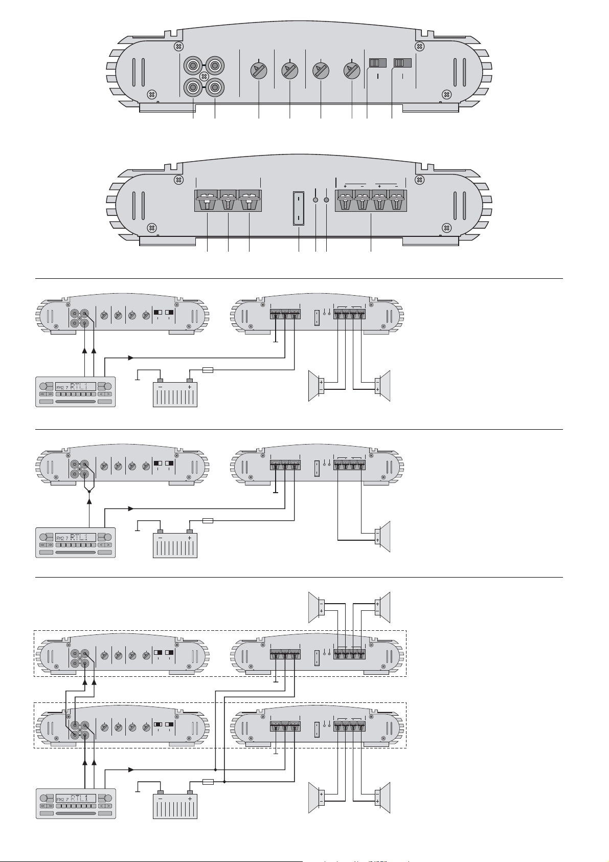
Bitte klappen Sie die Seite 3 heraus. Sie sehen
dann immer die beschriebenen Bedienelemente
und Anschlüsse.
1 Übersicht der Bedienelemente und
Anschlüsse
1.1 Frontseite
1 Line-Ausgänge OUTPUT;
hier liegt das durchgeschleifte Eingangssignal
der Buchsen INPUT (2) an (über 1 kΩ entkoppelt)
2 Cinch-Buchsen INPUT für das Eingangssignal
3 Regler LEVEL zur Eingangspegelanpassung
4 Regler BASS EQ zur Bassanhebung bis 12 dB
bei 50 Hz
5 Regler HP zum Einstellen der Trennfrequenz des
Hochpasses
6 Regler LP zum Einstellen der Trennfrequenz des
Tiefpasses
7 Schalter CROSSOVER zur Auswahl der Filter
FULL für Full-Range-Lautsprecher, kein Filter
eingeschaltet
LP für Basslautsprecher oder einen Sub-
woofer, Tiefpass eingeschaltet
HP für Mittelhochtöner, Hochpass einge-
schaltet
8 Schiebeschalter OUTPUT zum Umschalten zwi-
schen Mono- und Stereobetrieb
1.2 Rückseite
9 Masseanschluss GND
10 Steuereingang REM zum Einschalten der End-
stufe über eine 12-V-Spannung
11 Anschluss für die Versorgungsspannung +12V
12 Sicherungen
HPB-602: 1 x 30 A
HPB-1502: 2 x 30 A
Eine durchgebrannte Sicherung nur durch eine
gleichen Typs ersetzen!
13 Betriebsanzeige POWER
14 Anzeige PROT. leuchtet bei aktivierter Schutz-
schaltung:
1. wenn an einem der Lautsprecherausgänge
(15) ein Kurzschluss aufgetreten ist
2. wenn die Endstufe überhitzt ist
15 Lautsprecheranschlüsse SPEAKER
2 Sicherheitshinweise
Die Endstufe entspricht der Kfz-Richtlinie. Die Prüfnummer ist in den technischen Daten angeben.
●
Beim Anschluss der Car-HiFi-Endstufe an die Autobatterie ist besondere Sorgfalt geboten. Bei Kurzschlüssen können sehr gefährlich hohe Ströme
fließen. Schrauben Sie deshalb unbedingt vor dem
Anschluss die Minusklemme der Autobatterie ab.
●
Die Endstufe muss fest und fachgerecht an einer
mechanisch stabilen Stelle im Auto montiert werden, damit sie sich nicht löst und zu einem gefährlichen Geschoss wird.
●
Während des Betriebs kann das Gerät sehr heiß
werden. Platzieren Sie darum keine hitzeempfindlichen Gegenstände in der Nähe und berühren Sie
die Endstufe nicht während des Betriebs.
●
Verwenden Sie für die Reinigung nur ein trockenes, weiches Tuch, auf keinen Fall Chemikalien
oder Wasser.
●
Wird das Gerät zweckentfremdet, nicht richtig angeschlossen, falsch bedient oder nicht fachgerecht
repariert, kann keine Haftung für daraus resultierende Sach- oder Personenschäden und keine
Garantie für das Gerät übernommen werden.
3Vorsicht bei hohen Lautstärken
●
Stellen Sie die Lautstärke nie sehr hoch ein.
Extrem hohe Lautstärken können das Gehör
schädigen.
●
Das menschliche Ohr gewöhnt sich an hohe Lautstärken und empfindet sie nach einiger Zeit als
nicht mehr so hoch. Erhöhen Sie darum eine einmal eingestellte hohe Lautstärke nach der Gewöhnung nicht weiter.
●
Während des Autofahrens dürfen Signaltöne, z.B.
von einem Rettungswagen, nicht durch eine zu
hohe Lautstärke der Car-HiFi-Anlage übertönt
werden.
●
Bei ausgeschaltetem Motor sollte die Car-HiFiAnlage nicht längere Zeit mit hoher Lautstärke
betrieben werden. Die Autobatterie wird schnell
entladen und liefert dann eventuell nicht mehr genügend Energie zum Starten.
4 Einsatzmöglichkeiten
Die Endstufen HPB-602 und HPB-1502 sind speziell
für Car-HiFi-Anlagen konzipiert und können zwei
Full-Range-Lautsprecher (2- oder 3-Wege-Lautsprecher) antreiben. Durch die integrierten Frequenzweichen lässt sich mit einer zusätzlichen Endstufe auch ein 2-Wege-Aktivsystem mit zwei
Mittelhochtönern und zwei Basslautsprechern oder
einem Subwoofer realisieren (Bi-Amping). Um eine
größere Ausgangsleistung zu erhalten, kann die
Endstufe im Brückenbetrieb einen Lautsprecher
antreiben.
5 Montage
Bei der Auswahl des Montageplatzes unbedingt die
folgenden Punkte beachten:
●
Das 12-V-Stromversorgungskabel von der Batterie zur Car-HiFi-Endstufe sollte so kurz wie möglich sein. Es ist günstiger, längere Lautsprecherkabel zu verwenden und dafür ein kürzeres
Stromversorgungskabel.
Soll das Gerät endgültig aus dem Betrieb genommen werden, übergeben Sie
es zur umweltgerechten Entsorgung einem örtlichen Recyclingbetrieb.
Please unfold page 3. Then you can always see
the operating elements and connections described.
1 Operating Elements and Connections
1.1 Front panel
1 Line OUTPUT jacks;
the fed-through input signal of the jacks INPUT (2)
is present at these outputs (decoupled via 1 kΩ)
2 Phono jacks INPUT for the input signal
3 Control LEVEL for input level matching
4 Control BASS EQ for bass boosting up to 12 dB
at 50 Hz
5 Control HP for adjusting the crossover frequency
of the high pass
6 Control LP for adjusting the crossover frequency
of the low pass
7 Switch CROSSOVER for selecting the filters
FULL for full range speakers, no filter switched
on
LP for bass speakers or a subwoofer, low
pass switched on
HP for mid-high range speakers, high pass
switched on
8 Sliding switch OUTPUT for switching between
mono and stereo operation
1.2 Rear panel
9 Ground terminal GND
10 Control input REM for switching on the power
amplifier via a 12 V voltage
11 Terminal for the supply voltage +12 V
12 Fuses
HPB-602: 1 x 30 A
HPB-1502: 2 x 30 A
Only replace a blown fuse by one of the same
type!
13 POWER LED
14 LED PROT. lights up with activated protective
circuit:
1. if a short circuit has occurred at one of the
speaker outputs (15)
2. if the power amplifier is overheated
15 SPEAKER terminals
2 Safety Notes
The power amplifier corresponds to the directive for
automobiles. The test number is indicated in the
specifications.
●
When connecting the car HiFi power amplifier to
the car battery, be especially careful. In case of
short circuits there may be dangerously high currents. Therefore, prior to the connection, it is indispensable to screw off the negative terminal of the
car battery.
●
The power amplifier must be mounted to a
mechanically stable place in the car. It must be
skilfully fixed so that it does not get loose and turn
into a dangerous projectile.
●
During operation the unit may become very hot.
Therefore, do not place any objects sensitive to
heat near it and do not touch the power amplifier
while in operation.
●
For cleaning only use a dry, soft cloth, by no
means chemicals or water.
●
No guarantee claims for the unit and no liability for
any resulting personal damage or material
damage will be accepted if the unit is used for
other purposes than originally intended, if it is not
correctly connected or operated, or not repaired in
an expert way.
3 Caution in Case of High Volumes
●
Never adjust the volume very high. Extremely high
volumes may damage your hearing.
●
The human ear gets accustomed to high volumes
which do not seem to be so high any more after
some time. Therefore, do not increase a high
volume which has once been adjusted after getting used to it.
●
While driving in the car, signal sounds, e.g. by an
ambulance, must not be drowned by the volume
of the car HiFi system which has been adjusted
too high.
●
With the motor switched off, the car HiFi system
should not be in operation at high volume for a
longer period of time. The car battery will quickly
be discharged, and then it may not be capable any
more of supplying sufficient energy for starting the
car.
4 Applications
The power amplifiers HPB-602 and HPB-1502 have
especially been designed for car HiFi systems and
are able to drive two full range speakers (2-way or
3-way speakers). Due to the integrated crossover
networks, with an additional power amplifier it is also
possible to realize a 2-way active system with two
mid-high range speakers and two bass speakers or
a subwoofer (bi-amping). To obtain a higher output
power, the power amplifier can drive one speaker in
bridge operation.
5 Mounting
When choosing the place of mounting, always observe the following items in any case:
●
The 12 V power supply cable from the battery to
the car HiFi power amplifier should be as short as
possible. It is better to use longer speaker cables
and a shorter power supply cable instead.
If the unit is to be put out of operation
definitively, take it to a local recycling
plant for disposal which is not harmful to
the environment.
4
GB
D
A
CH
Page 5

●
Die Masseleitung von der Endstufe zum Fahrzeugchassis sollte ebenfalls so kurz wie möglich sein.
●
Um die entstehende Wärme der Car-HiFi-Endstufe ableiten zu können, muss eine ausreichende
Belüftung gewährleistet sein.
●
Wegen der beim Bremsen auftretenden Kräfte
muss die Endstufe an einer mechanisch stabilen
Stelle fest angeschraubt werden.
●
Die Sicherungen und die Regler müssen zugänglich sein.
Die Endstufe sollte elektrisch isoliert vom Fahrzeugchassis montiert werden. Die Endstufe mit den vier
Befestigungswinkeln an geeigneter Stelle festschrauben.
6 Endstufe anschließen
●
Der Anschluss der Car-HiFi-Endstufe an das Bordnetz darf nur durch qualifiziertes Fachpersonal
erfolgen.
●
Unbedingt vor dem Anschluss die Minusklemme
der Autobatterie abschrauben, um bei einem
eventuellen Kurzschluss während der Installation
Schäden zu vermeiden.
●
Die erforderlichen Kabel so verlegen, dass deren
Isolierung nicht beschädigt werden kann.
Der gesamte Anschluss ist in den Abbildungen 3 – 5
auf der Seite 3 dargestellt.
6.1 Stromversorgung
6.1.1 Betriebsspannung
Den Anschluss „+12V“ (11) über ein Starkstromkabel
mit der Plusklemme der Autobatterie verbinden. Um
den Spannungsverlust durch das Kabel gering zu
halten, sollte ein Kabel mit mindestens folgendem
Querschnitt verwendet werden:
HPB-602: 4 mm
2
, z. B. CPC-40 / RT*
HPB-1502: 10 mm
2
, z. B. CPC-100 / RT*
Um die neu verlegte 12-V-Leitung gegen einen
Kurzschluss abzusichern, muss eine Vorsicherung
in unmittelbarer Nähe der Batterie zwischengesetzt
werden (max. Kabellänge zur Batterie 20 cm):
HPB-602: 30 A
HPB-1502: 60 A
Zur Stabilisierung der Betriebsspannung für die
Endstufe und der damit verbundenen Leistungssteigerung sowie Klangverbesserung wird ein PowerKondensator empfohlen (z. B. CAP-…*).
6.1.2 Masseanschluss
Den Masseanschluss GND (9) über ein Starkstromkabel mit der Masse des Autos oder besser direkt
mit der Minusklemme der Autobatterie verbinden.
Der Querschnitt des Massekabels sollte mindestens
so groß sein wie der des Pluskabels:
HPB-602: 4 mm
2
, z. B. CPC-40 / SW*
HPB-1502: 10 mm
2
, z. B. CPC-100 / SW*
Hinweise
1. Bei Verwendung der Karosserie als Masseanschluss muss die verwendete Stelle einen guten
elektrischen Kontakt zur Hauptkarosserie aufweisen (z. B. durch ausreichend viele Schweißpunkte). Eventueller Lack am Kontaktpunkt muss
vollständig entfernt werden.
2. Zur Vermeidung von Masseschleifen muss die
Masse des Autoradios an die Stelle gelegt werden, an der auch die Endstufe an Masse liegt.
6.1.3 Steuerspannung zum Einschalten
Die Car-HiFi-Endstufe wird durch eine Steuerspannung von +12 V am Anschluss REM (10) ein- und
ausgeschaltet. Den Anschluss REM mit dem 12-VSchaltausgang vom Autoradio verbinden (z.B. Anschluss für eine Motorantenne, eventuell mit der
Motorantenne parallel schalten).
6.2 Eingänge
Die beiden Eingangsbuchsen INPUT (2) über CinchKabel mit den entsprechenden Line-Ausgängen am
Autoradio verbinden. Sind am Autoradio keine LineAusgänge vorhanden, können die Lautsprecherausgänge des Autoradios über einen Audio-Übertrager
(z. B. FGA-22HQ*) mit den Eingängen der Endstufe
verbunden werden.
6.2.1 Brückenbetrieb für den linken oder rechten Kanal
Soll die Endstufe im Brückenbetrieb einen Lautsprecher für den rechten oder linken Kanal antreiben,
die beiden Eingangsbuchsen INPUT (2) gemeinsam
über ein Y-Kabel (z. B. CBA-25 / SW*) mit dem LineAusgang des rechten bzw. linken Kanals am Autoradio verbinden – siehe auch Abb. 4.
6.2.2 Brückenbetrieb für einen Subwoofer
Soll im Brückenbetrieb ein Mono-Subwoofer angetrieben werden, eine der beiden folgenden Anschlussmöglichkeiten anwenden:
1. Sind am Autoradio Ausgänge für einen Subwoo-
fer-Verstärker vorhanden, diese mit den beiden
Eingangsbuchsen INPUT (2) verbinden.
2. Bei Autoradios ohne Subwoofer-Ausgang die
Line-Ausgänge für den linken und rechten Kanal
getrennt an die beiden Eingangsbuchsen INPUT,
wie in Abb. 3 dargestellt, anschließen.
6.3 Line-Ausgänge
Wird in der Car-HiFi-Anlage eine zweite Endstufe
eingesetzt, lassen sich deren Eingänge an die Ausgänge OUTPUT (1) anschließen (siehe Abb. 5), um
z. B. ein 2-Wege-Aktivsystem mit Mittelhochtönern
und Basslautsprechern oder einem Subwoofer zu
realisieren. An diesen Ausgängen liegt das gleiche
Signal an, welches auf die Eingänge INPUT (2)
gegeben wird.
●
The ground cable from the power amplifier to the
chassis of the car should also be as short as possible.
●
For carrying off the heat being generated by the
car HiFi power amplifier, a sufficient ventilation
has to be ensured.
●
As forces occur during braking, the power amplifier must tightly be screwed to a mechanically stable place.
●
The fuses and the controls must be accessible.
The power amplifier should be mounted electrically insulated from the car chassis. Tightly screw the amplifier with the four fixing brackets at a suitable place.
6 Connection of the Power Amplifier
●
The connection of the car HiFi power amplifier to
the electric system of the car must only be carried
out by authorized personnel.
●
To prevent damage in case of a possible short circuit during installation, prior to the connection it is
indispensable to screw off the negative terminal of
the car battery.
●
Lay the necessary cables so that their insulation
cannot be damaged.
The complete connection is shown in figs. 3 to 5 on
page 3.
6.1 Power supply
6.1.1 Operating voltage
Connect the terminal “+12V” (11) via a high current
cable to the positive terminal of the car battery. To
keep the voltage loss by the cable as low as possible, a cable with the minimum cross section as follows should be used:
HPB-602: 4 mm
2
, e. g. CPC-40 / RT*
HPB-1502: 10 mm
2
, e. g. CPC-100 / RT*
To protect the newly laid 12V cable against a short
circuit, insert an additional fuse very close to the battery (max. cable length to the battery 20 cm):
HPB-602: 30 A
HPB-1502: 60 A
To stabilize the operating voltage for the power
amplifier and thus the resulting power increase and
sound improvement, a power capacitor is recommended (e. g. CAP-…*).
6.1.2 Ground connection
Connect the ground terminal GND (9) via a high current cable to the ground of the car or better directly
to the negative terminal of the car battery. The cross
section of the ground cable should at least be the
same as that of the positive cable:
HPB-602: 4 mm
2
, e. g. CPC-40 / SW*
HPB-1502: 10 mm
2
, e. g. CPC-100 / SW*
Notes
1. When using the chassis as a ground connection,
the place used must have a good electrical
contact to the main chassis (e. g. by a sufficient
number of welding points). Any lacquer at the
point of contact must completely be removed.
2. To avoid ground loops, the ground of the car
radio must be applied at the place where also the
power amplifier is grounded.
6.1.3 Control voltage for switching-on
The car HiFi power amplifier is switched on and off
by a control voltage of +12 V at the terminal REM
(10). Connect the terminal REM to the 12 V control
output of the car radio (e. g. connection for a motor
antenna, if necessary, to be connected in parallel to
the motor antenna).
6.2 Inputs
Connect the two jacks INPUT (2) via cables with
phono connectors to the corresponding line outputs
at the car radio. If the car radio is not equipped with
line outputs, the speaker outputs of the car radio can
be connected via an transformer (e. g. FGA-22HQ*)
to the inputs of the power amplifier.
6.2.1 Bridge operation for the left channel or
right channel
If the power amplifier in bridge operation is to drive a
speaker for the right channel or left channel,
connect the two jacks INPUT (2) in common via a Y
cable (e. g. CBA-25 / SW*) to the line output of the
right channel or left channel at the car radio – also
see fig. 4.
6.2.2 Bridge operation for a subwoofer
If a mono subwoofer is to be driven in bridge operation, use one of the two following possibilities of
connection:
1. If the car radio is equipped with outputs for a sub-
woofer amplifier, connect them to the two jacks
INPUT (2).
2. For car radios without subwoofer output connect
the line outputs for the left channel and right
channel separately to the two jacks INPUT, as
shown in fig. 3.
6.3 Line outputs
If a second power amplifier is used in the car HiFi
system, the inputs of this amplifier can be connected
to the jacks OUTPUT (1) [see fig. 5] to realize e. g. a
2-way active system with mid-high range speakers
and bass speakers or a subwoofer. At these outputs
the same signal is present which is fed to the jacks
INPUT (2).
5
GB
D
A
CH
* von CARPOWER
* by CARPOWER
Page 6

6.4 Lautsprecher
Es lassen sich Full-Range-Lautsprecher (2- oder 3Wege-Lautsprecher), Mittelhochtöner, Basslautsprecher oder ein Subwoofer betreiben. Im 2-Kanalbetrieb kann die Endstufe die Lautsprecher für den
linken und rechten Kanal antreiben oder im
Brückenbetrieb mit erhöhter Ausgangsleistung den
Lautsprecher für einen Kanal oder einen Subwoofer.
6.4.1 2-Kanalbetrieb
Die größte Ausgangsleistung wird beim Anschluss
von 2-Ω-Lautsprechern oder einer Lautsprechergruppe mit einer Gesamtimpedanz von 2 Ω pro
Kanal erreicht (z. B. zwei 4-Ω-Lautsprecher parallel
geschaltet). Es können jedoch auch einzelne 4-Ω-
Lautsprecher angeschlossen werden, wobei sich die
Ausgangsleistung etwas verringert. Die Lautsprecher an die Klemmen SPEAKER (15) anschließen –
siehe auch Abb. 3:
L+ = Pluspol linker Lautsprecher
L
-
= Minuspol linker Lautsprecher
R+ = Pluspol rechter Lautsprecher
R
-
= Minuspol rechter Lautsprecher
6.4.2 Brückenbetrieb
Im Brückenbetrieb darf die Impedanz des angeschlossenen Lautsprechers bzw. die Gesamtimpedanz einer Lautsprechergruppe 4 Ω nicht unterschreiten! Den Lautsprecher an die Klemmen
SPEAKER (15) anschließen. Dabei die Beschriftung
BRIDGE beachten – siehe auch Abb. 4:
L+ = Pluspol
L
-
= bleibt frei
R+ = bleibt frei
R
-
= Minuspol
7 Inbetriebnahme
Für die meisten Anwendungen muss der Schalter
OUTPUT (8) in die Position STEREO geschoben
werden. Nur wenn die Endstufe zwei Lautsprecher
für den rechten oder linken Kanal antreiben soll und
nur eine Eingangsbuchse INPUT RIGHT oder LEFT
(2) angeschlossen ist, den Schalter auf MONO stellen.
7.1 Filter auswählen und Trennfrequenz einstellen
Je nach angeschlossenem Lautsprechertyp mit dem
Schalter CROSSOVER (7) das Filter auswählen.
Für Full-Range-Lautsprecher den Schalter ganz
nach links in die Position FULL schieben. Die Endstufe gibt den gesamten Frequenzbereich wieder.
Für Basslautsprecher oder einen Subwoofer den
Schalter in die Position LP schieben. Der Tiefpass
ist eingeschaltet und die mittleren sowie hohen Frequenzen werden unterdrückt. Die Trennfrequenz mit
dem Regler LP (6) zunächst grob einstellen.*
Für Mittelhochtöner den Schalter in die Position
HP schieben. Der Hochpass ist eingeschaltet und
die tiefen Frequenzen werden damit unterdrückt.
Die Trennfrequenz mit dem Regler HP (5) zunächst
grob einstellen.*
7.2 Pegel und Bassanhebung einstellen
1) Den Regler LEVEL (3) ganz nach links in die
Position MIN drehen.
2) Die Car-HiFi-Anlage komplett einschalten. Die
grüne Betriebsanzeige POWER (13) leuchtet.
Die Endstufe bleibt jedoch noch für ca. 3 Sekunden stumm geschaltet (Einschaltverzögerung).
3) Die Signalquelle, z. B. das Autoradio, auf maximale, nicht verzerrende Lautstärke einstellen.
4) Den Regler LEVEL (3) maximal so weit aufdrehen, dass keine Verzerrungen auftreten.
5) Bei Bedarf lassen sich die Bässe mit dem Regler
BASS EQ (4) anheben (max. 12 dB / 50 Hz).
6) Sind in der Car-HiFi-Anlage weitere Endstufen
eingesetzt, zur Anpassung der Lautstärke aller
Kanäle untereinander die jeweils zu lauten
Kanäle im Pegel reduzieren.
8 Fehlerbeseitigung
Ist nach dem Einschalten der Car-HiFi-Anlage kein
Ton zu hören, den Fehler mithilfe der beiden LEDs
POWER (13) und PROT. (14) näher lokalisieren.
Die LED POWER leuchtet nicht
1) Die Sicherungen (12) der Car-HiFi-Endstufe
HPB-602: 1 x 30 A
HPB-1502: 2 x 30 A
und die Vorsicherung an der Autobatterie
HPB-602: 30 A
HPB-1502: 60 A
überprüfen. Defekte Sicherungen auswechseln.
Nur Sicherungen mit den angegebenen Werten
Tipp Um Störeinstrahlungen durch die Autoelek-
trik so gering wie möglich zu halten, sollte
der Ausgangspegel der Signalquelle min.
1,5 V betragen.
Wichtig!
Vor dem ersten Einschalten das Filter mit dem
Schalter CROSSOVER (7) auswählen und die
Trennfrequenz grob einstellen (Kap. 7.1), damit die
Lautsprecher nicht durch einen eventuell zu
großen Frequenzbereich überlastet werden. Auch
sollte die komplette Verdrahtung der Car-HiFiEndstufe noch einmal auf Richtigkeit überprüft
werden. Erst danach die Minusklemme der Autobatterie wieder anschließen.
Wichtig!
Alle Lautsprecher müssen 2-polig angeschlossen
werden, d. h. ohne gemeinsamen Masseanschluss.
Bei der Auswahl geeigneter Lautsprecher unbedingt deren mechanische und elektrische Belastbarkeit im Zusammenhang mit der genutzten
Endstufenleistung berücksichtigen (siehe auch
technische Daten der Endstufe auf Seite 7).
6.4 Speakers
It is possible to use full range speakers (2-way or
3-way speakers), mid-high range speakers, bass
speakers, or a subwoofer. In 2-channel operation
the power amplifier can drive the speakers for the
left channel and right channel or in bridge operation
with increased output power it can drive the speaker
for one channel or a subwoofer.
6.4.1 2-channel operation
The highest output power is reached when connecting 2 Ω speakers or a speaker group with a total
impedance of 2 Ω per channel (e. g. two 4Ω speakers connected in parallel). However, it is also possible to connect individual 4 Ω speakers in which
case the output power is slightly reduced. Connect
the speakers to the terminals SPEAKER (15) – also
see fig. 3:
L+ = positive pole left speaker
L
-
= negative pole left speaker
R+ = positive pole right speaker
R
-
= negative pole right speaker
6.4.2 Bridge operation
In bridge operation the impedance of the connected
speaker or the total impedance of a speaker group
must not fall below 4 Ω! Connect the speaker to the
terminals SPEAKER (15). Pay attention to the lettering BRIDGE – also see fig. 4:
L+ = positive pole
L
-
= remains unconnected
R+ = remains unconnected
R
-
= negative pole
7 Setting into Operation
For most applications the switch OUTPUT (8) must
be set to the position STEREO. Only if the power
amplifier is to drive two speakers for the right channel or the left channel and only one jack INPUT
RIGHT or LEFT (2) is connected, set the switch to
MONO.
7.1 Selecting the filter and adjusting the
crossover frequency
Depending on the speaker type connected, select
the filter with the switch CROSSOVER (7).
For full range speakers set the switch to the left
stop to position FULL. The power amplifier reproduces the entire frequency range.
For bass speakers or a subwoofer set the switch
to position LP. The low pass is switched on and the
medium and high frequencies are suppressed. For
the time being, coarsely adjust the crossover frequency with the control LP (6).*
For mid-high range speakers set the switch to
position HP. The high pass is switched on and the
low frequencies are thus suppressed. For the time
being, coarsely adjust the crossover frequency with
the control HP (5).*
7.2 Adjusting the level and the bass boosting
1) Turn the control LEVEL (3) to the left stop to position MIN.
2) Switch on the car HiFi system completely. The
green POWER LED (13) lights up. However, the
power amplifier is muted for approx. 3 seconds
(switch-on delay).
3) Adjust the signal source, e. g. the car radio, to the
maximum, non-distorting volume.
4) Turn up the control LEVEL (3) so far as a maximum that no distortions occur.
5) If required, the bass frequencies can be boosted
with the control BASS EQ (4) [max. 12 dB/ 50 Hz].
6) If further power amplifiers are used in the car HiFi
system, reduce in each case the levels of the
channels which are too high to match the volumes of all channels with each other.
8Trouble Shooting
If there is no sound after switching on the car HiFi
system, locate the fault more precisely by means of
the two LEDs POWER (13) and PROT. (14).
The LED POWER does not light up
1) Check the fuses (12) of the car HiFi power amplifier
HPB-602: 1 x 30 A
HPB-1502: 2 x 30 A
and the additional fuse at the car battery
HPB-602: 30 A
HPB-1502: 60 A
Replace defective fuses. Only use fuses with the
indicated values. Do not insert a fuse of a higher
Hint To keep the interference by the electric
system of the car as low as possible, the output level of the signal source should be 1.5 V
as a minimum.
Important!
Prior to the first switching-on, select the filter with
the switch CROSSOVER (7) and coarsely adjust
the crossover frequency (chapter 7.1) so that the
speakers will not be overloaded by a frequency
range that might be too wide. It is also recommended to check the entire wiring of the car HiFi power
amplifier once again for correctness before connecting the negative terminal of the car battery
again.
Important!
All speakers must be connected with 2 poles, i. e.
without common ground connection. When choosing suitable speakers, pay in any case attention to
their mechanical and electrical capability in connection with the power used of the power amplifier
(also see specifications of the power amplifier on
page 7).
6
GB
D
A
CH
*Zur Orientierung den Frequenzbereich der eingesetzten
Lautsprecher beachten. Die Feineinstellung erfolgt nach
der Pegeleinstellung mit entsprechenden Messgeräten.
*For a guidance, observe the frequency range of the
speakers used. The fine adjustment is made with corresponding meters after the level adjustment.
Page 7

verwenden. Auf keinen Fall einen höheren Wert
einsetzen. Die Endstufe kann beschädigt werden
und die Garantie erlischt.
2) Das 12-V-Stromversorgungskabel sowie das
Massekabel auf korrekten Anschluss und Unterbrechung kontrollieren.
3) An der Klemme REM (10) der Endstufe messen,
ob +12 V anliegt. Wenn nicht, die Leitung an der
Klemme REM entfernen und vorübergehend die
Klemmen REM und „+12V“ (11) überbrücken.
Schaltet die Endstufe jetzt ein, liegt der Fehler in
der fehlenden Steuerspannung. Den 12-V-Schaltausgang des Autoradios und das entsprechende
Anschlusskabel zur Endstufe überprüfen.
Die LED POWER leuchtet
1) Die Cinch-Leitungen von der Signalquelle zur
Car-HiFi-Endstufe überprüfen. Sind die Stecker
richtig eingesteckt? Sind die Leitungen unterbrochen?
2) Die Signalquelle überprüfen. Ist die Signalquelle
eingeschaltet? Sind die richtigen Ausgänge verwendet worden? Ist die Signalquelle defekt?
3) Die Lautsprecherkabel auf Unterbrechung überprüfen.
4) Die angeschlossenen Lautsprecher überprüfen.
Die LED PROT. leuchtet
Die Endstufe ist mit einer Schutzschaltung gegen
Kurzschluss an den Lautsprecherausgängen und
gegen Überhitzung gesichert. Ist die Schutzschaltung aktiviert, leuchtet die Anzeige PROT. (14). Bei
einer Überhitzung schaltet die Endstufe nach dem
Abkühlen automatisch wieder ein. Bei einem Kurzschluss an den Lautsprecherausgängen muss nach
der Fehlerbeseitigung zum Zurücksetzen der
Schutzschaltung die 12-V-Steuerspannung kurz
abgeschaltet werden (z. B. Autoradio ausschalten).
9Technische Daten
value in any case. The power amplifier may be
damaged and the guarantee expires.
2) Check the 12 V power supply cable and the
ground cable for correct connection and for interruption.
3) Check at the terminal REM (10) of the power
amplifier if +12 V is present. If not, remove the
cable at the terminal REM and for a short time
short-circuit the terminals REM and “+12V” (11).
If the power amplifier switches on now, the fault is
due to the missing control voltage. Check the
12 V control output of the car radio and the corresponding connection cable to the power amplifier.
The LED POWER lights up
1) Check the cables with phono connectors from the
signal source to the car HiFi power amplifier. Are
the plugs correctly connected? Are the cables
interrupted?
2) Check the signal source. Is the signal source
switched on? Have the correct outputs been
used? Is the signal source defective?
3) Check the speaker cables for interruption.
4) Check the connected speakers.
LED PROT. lights up
The power amplifier is protected with a protective
circuit against short circuit at the speaker outputs
and against overheating. If the protective circuit is
activated, the LED PROT. (14) lights up. In case of
overheating the power amplifier automatically
switches on again after cooling down. In case of a
short circuit at the speaker outputs, after eliminating
the error, the 12V control voltage must shortly be
switched off (e. g. switch off the car radio) to reset
the protective circuit.
9 Specifications
7
GB
D
A
CH
Diese Bedienungsanleitung ist urheberrechtlich für MONACOR®INTERNATIONAL GmbH & Co. KG
geschützt. Eine Reproduktion für eigene kommerzielle Zwecke – auch auszugsweise – ist untersagt.
All rights reserved by MONACOR
®
INTERNATIONAL GmbH & Co. KG. No part of this instruction manual
may be reproduced in any form or by any means for any commercial use.
Änderungen vorbehalten.
Subject to technical modification.
HPB-602 HPB-1502
Ausgangsleistung
Gesamtleistung
2-Kanalbetrieb an 2-Ω-Lautsprecher
2-Kanalbetrieb an 4-Ω-Lautsprecher
Brückenbetrieb an 4-Ω-Lautsprecher
350 W
MAX
2 x 100 WRMS
2 x 70 WRMS
1 x 225 WRMS
750 WMAX
2 x 250 WRMS
2 x 175 WRMS
1 x 500 WRMS
Frequenzbereich 20 – 20 000 Hz 20 – 20 000 Hz
minimale Lautsprecherimpedanz
2-Kanalbetrieb
Brückenbetrieb
2 Ω
4 Ω
2 Ω
4 Ω
Eingänge
0,4 – 4 V/20 kΩ 0,4 – 4 V/20 kΩ
Kanaltrennung > 45 dB > 50 dB
Störabstand > 94 dB (bewertet) > 89 dB (bewertet)
Klirrfaktor < 0,2 % < 0,2 %
Filter
Tiefpass
Hochpass
40 – 300 Hz, 6dB/Okt.
40 – 500 Hz, 6dB/Okt.
40 – 300 Hz, 6dB/Okt.
40 – 500 Hz, 6dB/Okt.
Bassanhebung 0 – 12 dB/50 Hz 0 – 12 dB/50 Hz
zulässige Einsatztemperatur 0 –40 °C 0 – 40 °C
Abmessungen (B x H x T) 252 x 62 x 243 mm 252 x 62 x 363 mm
Gewicht 2 kg 3,5 kg
Prüfnummer e24 020984 e24 021068
Stromversorgung
10 – 16 V /22A
10 – 16 V /45A
HPB-602 HPB-1502
Output power
Total power
2-channel operation with 2 Ω speakers
2-channel operation with 4 Ω speakers
Bridge operation with 4 Ω speakers
350 W
MAX
2 x 100 WRMS
2 x 70 WRMS
1 x 225 WRMS
750 W
MAX
2 x 250 WRMS
2 x 175 WRMS
1 x 500 WRMS
Frequency range 20– 20000 Hz 20 –20 000Hz
Minimum speaker impedance
2-channel operation
Bridge operation
2 Ω
4 Ω
2 Ω
4 Ω
Inputs
0.4 – 4 V/20 kΩ 0.4 – 4 V/20 kΩ
Channel separation > 45 dB > 50 dB
S/N ratio
> 94 dB (weighted) > 89 dB (weighted)
THD < 0.2 % < 0.2 %
Filters
Low pass
High pass
40 – 300 Hz, 6dB/oct.
40 – 500 Hz, 6dB/oct.
40 – 300 Hz, 6dB/oct.
40 – 500 Hz, 6dB/oct.
Bass boosting 0 – 12 dB/50 Hz 0 – 12 dB/50 Hz
Admissible ambient temperature 0 – 40 °C 0 – 40 °C
Dimensions (W x H x D) 252 x 62 x 243 mm 252 x 62 x 363 mm
Weight 2 kg 3.5 kg
Test number e24 020984 e24 021068
Power supply
10 – 16 V /22A
10 – 16 V /45A
Page 8

Ouvrez le présent livret page 3 de manière à
visualiser les éléments et branchements.
1 Eléments et branchements
1.1 Face avant
1 Sorties Ligne OUTPUT ;
le signal d’entrée repiqué des prises INPUT (2)
est présent (découplé via 1 kΩ)
2 Prises RCA INPUT pour le signal d’entrée
3 Potentiomètre de réglage LEVEL pour l’adapta-
tion de niveau d’entrée
4 Potentiomètre de réglage BASS EQ pour l’aug-
mentation des graves jusqu’à 12 dB à 50 Hz
5 Potentiomètre de réglage HP pour régler la fré-
quence de coupure du passe-haut
6 Potentiomètre de réglage LP pour régler la fré-
quence de coupure du passe-bas
7 Interrupteur CROSSOVER pour sélectionner les
filtres :
FULL pour haut-parleurs Full Range, aucun fil-
tre allumé
LP pour haut-parleurs de grave ou un sub-
woofer, passe-bas allumé
HP pour haut-parleurs de médium-aigu,
passe-haut allumé
8 Potentiomètre à glissières OUTPUT pour com-
muter entre mode mono et stéréo
1.2 Face arrière
9 Branchement masse GND
10 Entrée de commande REM pour allumer l’ampli-
ficateur via une tension 12 V
11 Branchement pour la tension d’alimentation +12 V
12 Fusibles
HPB-602 : 1 x 30 A
HPB-1502 : 2 x 30 A
Tout fusible fondu doit être remplacé uniquement
par un fusible de même type!
13 Témoin de fonctionnement POWER
14 Affichage PROT. : brille si le circuit de protection
est activé :
1. Si un court-circuit est survenu à une des sorties haut-parleurs (15)
2. Si l’amplificateur est en surchauffe
15 Bornes haut-parleurs SPEAKER
2 Conseils d’utilisation et de sécurité
Cet amplificateur répond à la directive sur les véhicules. Le numéro de test est indiqué dans les caractéristiques techniques.
●
Lorsque vous reliez l’amplificateur à la batterie de
la voiture, soyez très prudent ; en cas de court-circuit, des courants très élevés et donc dangereux
peuvent circuler. C’est pourquoi avant tout branchement, n’oubliez pas de dévisser la borne
moins de la batterie.
●
L’appareil doit être solidement fixé dans un endroit
mécaniquement stable pour éviter qu’il ne se
dévisse et ne se transforme en projectile dangereux.
●
Pendant son fonctionnement, il peut devenir très
chaud ; ne placez pas à proximité d’objets sensibles à la chaleur et ne le touchez pas pendant son
fonctionnement.
●
Pour le nettoyer, utilisez un chiffon sec et doux, en
aucun cas de produits chimiques ou d’eau.
●
Nous déclinons toute responsabilité en cas de
dommages matériels ou corporels résultants si
l’appareil est utilisé dans un but autre que celui
pour lequel il a été conçu, s’il n’est pas correctement branché, utilisé ou n’est pas réparé par une
personne habilitée, en outre, la garantie deviendrait caduque.
3 Mises en garde en cas de volume
élevé
●
Ne réglez jamais le volume trop fort. Des volumes
extrêmement élevés peuvent endommager l’ouïe.
●
L’oreille humaine s’habitue à des volumes élevés
et, après un certain temps, ne les perçoit plus de
la même manière. C’est pourquoi n’augmentez
pas le volume une fois que vous y êtes habitué.
●
Pendant la conduite, les bruits extérieurs, par
exemple, une ambulance, ne doivent pas être
masqués par un volume trop fort de l’installation
de Hi-Fi embarquée.
●
Lorsque le véhicule est éteint, le système de Hi-Fi
embarquée ne devrait pas fonctionner trop longtemps avec un volume élevé ; la batterie du véhicule se déchargerait rapidement et ne serait plus
en mesure de fournir une puissance suffisante
pour démarrer.
4 Possibilités d’utilisation
Les amplificateurs HPB-602 et HPB-1502 sont spécialement conçus pour une installation dans des
systèmes de Hi-Fi embarquée et peuvent faire fonctionner deux haut-parleurs Full Range (système 2 ou
3 voies). Grâce aux filtres de fréquences intégrés et
avec un amplificateur supplémentaire, il est également possible d’obtenir un système actif 2 voies
avec deux haut-parleurs médium aigu et deux hautparleurs de grave ou un subwoofer (bi-amplification). Pour obtenir une plus grande puissance de
sortie, l’amplificateur peut faire fonctionner un hautparleur en mode bridgé.
5 Montage
Lorsque vous choisissez le lieu d’installation de l’appareil, respectez impérativement les points suivants :
●
Le cordon d’alimentation 12 V reliant la batterie à
l’amplificateur devrait être aussi court que possible ;
il est préférable d’utiliser des câbles haut-parleurs
plus longs et un cordon d’alimentation plus court.
Lorsque l’appareil est définitivement
retiré du circuit de distribution, vous
devez le déposer dans une usine de
recyclage adaptée pour contribuer à son
élimination non polluante.
Vi preghiamo di aprire completamente la pagina 3.
Così vedrete sempre gli elementi di comando e i
collegamenti descritti.
1 Elementi di comando e collegamenti
1.1 Pannello frontale
1 Uscita Line OUTPUT;
qui è presente il segnale d’ingresso di attraversamento delle prese INPUT (2) [disaccoppiato
oltre 1 kΩ]
2 Prese RCA INPUT per il segnale d’ingresso
3 Regolatore LEVEL per l’adattamento del livello
d’ingresso
4 Regolatore BASS EQ per aumentare i bassi fino
a 12 dB a 50 Hz
5 Regolatore HP per impostare la frequenza di
taglio del passaalto
6 Regolatore LP per impostare la frequenza di ta-
glio del passabasso
7 Selettore CROSSOVER per scegliere il filtro
FULL per altoparlanti a larga banda, nessun fil-
tro attivato
LP per woofer o un subwoofer, passabasso
attivato
HP per tweeter/midrange, passaalto attivato
8 Cursore OUTPUT per cambiare fra funziona-
mento mono e stereo
1.2 Pannello posteriore
9 Contatto di massa GND
10 Ingresso di comando REM per attivare lo stadio
finale tramite una tensione 12 V
11 Collegamento per la tensione di alimentazione
+12 V
12 Fusibili
HPB-602: 1 x 30 A
HPB-1502: 2 x 30 A
Sostituire un fusibile difettoso sempre con uno
dello stesso tipo!
13 Spia di funzionamento POWER
14 Spia PROT., è accesa quando il circuito di prote-
zione è attivato:
1. se ad una delle uscite per altoparlanti (15) è
presente un cortocircuito
2. se lo stadio finale è surriscaldato
15 Contatti per altoparlanti SPEAKER
2Avvertenze di sicurezza
Il finale di potenza è conforme alla direttiva per autovetture. Il numero di omologazione è indicato fra i
dati tecnici.
●
Usare particolare cura nel collegare il finale di
potenza hifi con la batteria dell’auto. Nel caso di
cortocircuiti ci possono essere delle correnti molto
alte. Prima del collegamento scollegare assolutamente il polo negativo della batteria.
●
Il finale dev’essere montato in un modo solido e
corretto in un posto meccanicamente sicuro dell’auto per evitare che si possa staccare, diventando pericoloso in caso di incidente.
●
Durante il funzionamento, l’amplificatore può riscaldarsi molto. Non mettere nelle sue vicinanze
oggetti sensibili al calore e non toccare l’amplificatore.
●
Per la pulizia usare solo un panno asciutto e seco;
non impiegare in nessun caso prodotti chimici o
acqua.
●
Nel caso di uso improprio, di comandi sbagliati, di
collegamenti errati o di riparazione scorretta non
si assume nessuna responsabilità per eventuali
danni consequenziali a cose o persone e non si
assume nessuna responsabilità per l’apparecchio.
3 Attenzione col volume alto
●
Non alzare troppo il volume. Il volume troppo alto
può danneggiare l’udito.
●
L’orecchio si abitua al volume alto e dopo un certo
periodo non se ne accorge più. Pertanto conviene
non aumentare il volume alto impostato inizialmente.
●
Mentre si guida l’auto, i segnali di ambulanze ecc.
non devono essere coperti dal volume dell’impianto audio.
●
Non fare funzionare l’impianto hifi dell’auto col
volume alto mentre il motore è spento. La batteria
dell’auto si scarica velocemente con il rischio di
non poter fornire energia sufficiente per l’avvio
della macchina.
4 Possibilità d’impiego
I finali di potenza HPB-602 e HPB-1502 sono previsti specialmente per impianti hi-fi nelle auto e possono comandare due altoparlanti a larga banda (sistemi a 2 o 3 vie). Con i filtri integrati e con un finale
supplementare è possibile realizzare anche un
sistema attivo a 2 vie con due midrange/ tweeter e
due woofer o un subwoofer (bi-amping). Per aumentare la potenza d’uscita, l’amplificatore può, con collegamento a ponte, pilotare un solo altoparlante.
5 Montaggio
Nella scelta di un posto per il montaggio occorre
assolutamente considerare i seguenti punti:
●
Il cavo di alimentazione 12 V dalla batteria al finale
hifi deve essere il più corto possibile. È preferibile
usare lunghi cavi per gli altoparlanti e tenere corto
il cavo di alimentazione.
●
Anche il cavo della massa dal finale al telaio della
macchina deve essere il più corto possibile.
●
Per poter dissipare il calore sprigionato dal finale
deve essere garantita una ventilazione sufficiente.
Se si desidera eliminare l’apparecchio
definitivamente, consegnarlo per lo
smaltimento ad un’istituzione locale per
il riciclaggio.
8
I
F
B
CH
Page 9

●
Le câble de la masse reliant l’amplificateur au
châssis du véhicule devrait être aussi court que
possible.
●
Pour permettre une évacuation correcte de la chaleur dégagée par l’amplificateur, veillez à assurer
une ventilation suffisante.
●
Acause des forces résultantes lors d’un freinage,
l’amplificateur doit être vissé correctement à un
endroit mécaniquement stable.
●
Les fusibles et les réglages doivent être faciles
d’accès.
Il convient de brancher l’amplificateur de manière
électriquement isolée du châssis du véhicule. Vissez l’amplificateur avec les quatre étriers de fixation
à l’endroit adéquat.
6 Branchements
●
Le branchement de l’amplificateur à l’alimentation
du véhicule ne doit être effectué que par un technicien habilité.
●
Pour éviter tout dégât, en cas de court-circuit
éventuel lors de l’installation, dévissez impérativement la borne moins de la batterie de la voiture.
●
Placez les câbles nécessaires de telle sorte que
leur isolation ne soit pas endommagée.
Les schémas 3 à 5, page 3, présentent l’ensemble
des branchements.
6.1 Alimentation
6.1.1 Tension de fonctionnement
Reliez la borne “+12V” (11) via un cordon courants
forts à la borne plus de la batterie du véhicule. Pour
que les pertes de tension générées par le câble
soient les plus faibles possibles, la section minimale
du câble utilisé devrait être de :
HPB-602 : 4 mm
2
, par exemple CPC-40/ RT*
HPB-1502 : 10 mm
2
, par exemple CPC-100/ RT*
Pour protéger le cordon 12 V nouvellement installé
contre tout court-circuit, il faut insérer à proximité
immédiate de la batterie un fusible (longueur maximale du câble à la batterie 20 cm) :
HPB-602 : 30 A
HPB-1502 : 60 A
Pour stabiliser la tension de fonctionnement pour
l’amplificateur, l’augmentation de puissance résultante et l’amélioration du son, il est recommandé
d’utiliser un condensateur de puissance (par exemple CAP-…*).
6.1.2 Branchement masse
Reliez la borne masse GND (9) via un cordon courants forts à la masse du véhicule ou encore mieux,
directement à la borne moins de la batterie de la voiture. La section du câble de masse devrait être au
moins aussi grande que celle du câble plus :
HPB-602 : 4 mm
2
, par exemple CPC-40/ SW*
HPB-1502 : 10 mm
2
, par exemple CPC-100/ SW*
Conseils :
1. Si vous utilisez la carrosserie comme branchement masse, l’endroit utilisé doit avoir un bon
contact électrique avec la carrosserie principale
(par exemple avec un nombre de points de soudure suffisant). Il faut enlever tout point de laque
sur le point de contact.
2. Pour éviter tout bouclage de masse, la masse de
l’autoradio doit être placée à l’endroit où l’amplificateur est aussi à la masse.
6.1.3 Tension de commande pour allumer
L’amplificateur de Hi-Fi embarquée est allumé et
éteint par une tension de commande de +12 V à la
borne REM (10). Reliez la borne REM à la sortie
12 V de l’autoradio (p. ex. branchement pour une
antenne motorisée, si nécessaire à brancher en parallèle à l’antenne motorisée).
6.2 Entrées
Reliez les deux prises d’entrée INPUT (2) via des
cordons RCA aux sorties Ligne correspondantes sur
l’autoradio. Si l’autoradio n’est pas doté de sorties
Ligne, les sorties haut-parleurs de l’autoradio peuvent être reliées aux entrées de l’amplificateur via
un transformateur adapté (par ex. FGA-22HQ*).
6.2.1 Mode bridgé pour le canal gauche ou droit
Si l’amplificateur en mode bridgé doit faire fonctionner un haut-parleur pour le canal droit ou le
canal gauche, reliez les deux prises d’entrée INPUT
(2) ensemble via un cordon en Y (par exemple
CBA-25/ SW*) avec la sortie Ligne du canal droit ou
gauche sur l’autoradio – voir également schéma 4.
6.2.2 Mode bridgé pour un subwoofer
Si en mode bridgé un subwoofer mono doit fonctionner, utilisez une des deux possibilités de montage suivantes :
1. Si sur l’autoradio des sorties pour un amplificateur subwoofer sont prévues, reliez-les aux deux
prises d’entrée INPUT (2).
2. Pour des autoradios sans sortie subwoofer, reliez
les sorties Ligne pour le canal droit et le canal
gauche séparément aux deux prises d’entrée
INPUT, comme décrit sur le schéma 3.
6.3 Sorties Ligne
Si dans l’installation de Hi-Fi embarquée, un second
amplificateur est installé, ses entrées peuvent être
reliées aux sorties OUTPUT (1) [voir schéma 5] pour
réaliser par exemple un système actif deux voies
avec haut-parleurs de médium-aigu et haut-parleurs
de grave ou avec un subwoofer. Le même signal
que celui appliqué aux entrées INPUT (2), est présent à ces sorties.
●
Per le forze che si manifestano nelle frenate, il
punto di montaggio deve essere meccanicamente
stabile.
●
I fusibili e i regolatori devono essere accessibili.
Il finale deve essere montato con isolamento
elettrico dal telaio della vettura. Avvitare lo stadio
finale in un posto adatto servendosi dei quattro
angoli di fissaggio.
6 Collegare il finale
●
Il collegamento del finale con la rete di bordo
dev’essere eseguito solo da personale qualificato.
●
Per evitare eventuali cortocircuiti durante l’installazione con danni conseguenti, prima del montaggio scollegare il polo negativo della batteria auto.
●
Sistemare i cavi in modo tale che l’isolamento non
possa subire danni.
Le figure 3 – 5 a pagina 3 illustrano tutti i collegamenti.
6.1 Alimentazione
6.1.1 Tensione d’esercizio
Collegare il contatto “+12V” (11) con il positivo della
batteria dell’auto per mezzo di un cavo per corrente
forte. Per ridurre la perdita di tensione per mezzo del
cavo, si dovrebbe usare un cavo con la seguente
sezione minima:
HPB-602: 4 mm
2
, p. es. CPC-40 / RT*
HPB-1502: 10 mm
2
, p. es. CPC-100 / RT*
Per proteggere la nuova linea 12 V contro i cortocircuiti, occorre inserire un fusibile supplementare
nella diretta vicinanza della batteria (lunghezza
massima del cavo verso la batteria 20 cm):
HPB-602: 30 A
HPB-1502: 60 A
Per stabilizzare la tensione d’esercizio per il finale e
quindi l’aumento di potenza nonché il miglioramento
sonoro, si consiglia l’uso di un condensatore di
potenza (p. es. CAP-…*).
6.1.2 Collegamento della massa
Collegare il contatto della massa GND (9) con la
massa dell’auto, o meglio, direttamente con il polo
negativo della batteria. La sezione del cavo di
massa dovrebbe essere non inferiore a quella del
cavo positivo:
HPB-602: 4 mm
2
, p. es. CPC-40 / SW*
HPB-1502: 10 mm
2
, p. es. CPC-100 / SW*
N.B.:
1. Usando la carrozzeria come massa, il punto
usato deve presentare un buon contatto elettrico
con la carrozzeria principale (p. es. tramite un
numero sufficiente di punti di saldatura). La vernice eventualmente presente deve essere tolta
completamente.
2. Per evitare l’effetto di anelli di terra, la massa
dell’autoradio deve essere collegata allo stesso
punto in cui è collegata la massa del finale.
6.1.3 Tensione di comando per l’accensione
Il finale di potenza hifi per auto si accende e si
spegne tramite una tensione di comando di +12 V al
contatto REM (10). Collegare il contatto REM con
l’uscita di commutazione di 12 V dell’autoradio
(p. es. collegamento di un’antenna motorizzata;
eventualmente collegare in parallelo con l’antenna).
6.2 Ingressi
Collegare le due prese d’ingresso INPUT (2) con le
uscite Line dell’autoradio usando cavi RCA. Se l’autoradio non possiede nessun’uscita Line, le uscite
per gli altoparlanti dell’autoradio possono essere
collegate con gli ingressi del finale per mezzo di un
adattatore audio (p. es. FGA-22HQ*).
6.2.1 Funzionamento a ponte per il canale sinistro o destro
Se l’amplificatore collegato a ponte deve pilotare un
altoparlante per il canale di destra oppure di sinistra, collegare le due prese d’ingresso INPUT (2)
insieme con l’uscita Line del canale destro o sinistro
dell’autoradio, servendosi di un cavo ad Y (p.es.
CBA-25/ SW*) – vedi anche fig. 4.
6.2.2 Funzionamento a ponte per un subwoofer
Se con un collegamento a ponte viene usato un subwoofer mono, si può scegliere fra una delle due possibilità di collegamento:
1. se l’autoradio possiede delle uscite per un ampli-
ficatore per subwoofer, collegarle con le due
prese d’ingresso INPUT (2);
2. nel caso di un’autoradio senza uscita subwoofer,
collegare le uscite Line per il canale di sinistra e
di destra separatamente con le due prese d’ingresso INPUT come illustrato in fig. 3.
6.3 Uscite Line
Se nell’impianto car-hifi si impiega un secondo stadio finale, i suoi ingressi si possono collegare con le
uscite OUTPUT (1) [vedi fig. 5], per esempio per
realizzare un sistema attivo a 2 vie con dei midrange/ tweeter e un woofer o subwoofer. A queste
uscite è presente il segnale che viene applicato agli
ingressi INPUT (2).
9
I
F
B
CH
* de CARPOWER
* di CARPOWER
Page 10

6.4 Haut-parleurs
Il est possible d’utiliser des haut-parleurs Full Range
(systèmes 2 voies ou 3 voies), de médium aigu, de
grave ou un subwoofer. En mode deux canaux,
l’amplificateur peut faire fonctionner les haut-parleurs pour le canal droit et le canal gauche ou en
mode bridgé avec une puissance de sortie plus élevée, le haut-parleur pour un canal ou un subwoofer.
6.4.1 Mode deux canaux
La puissance de sortie la plus grande est atteinte
lorsque des haut-parleurs 2 Ω ou un groupe de hautparleurs avec une impédance totale de 2 Ω par
canal sont branchés (par exemple deux haut-parleurs 4 Ω branchés en parallèle). Il est possible de
brancher des haut-parleurs 4 Ω individuels mais
dans ce cas, la puissance de sortie est un peu diminuée. Reliez les haut-parleurs aux bornes SPEAKER (15) – voir également schéma 3 :
L+ = pôle plus haut-parleur gauche
L
-
= pôle moins haut-parleur gauche
R+ = pôle plus haut-parleur droit
R
-
= pôle moins haut-parleur droit
6.4.2 Mode bridgé
En mode bridgé, l’impédance du haut-parleur relié
ou l’impédance totale d’un groupe de haut-parleurs
ne doit pas être inférieure à 4 Ω. Reliez le haut-parleur aux bornes SPEAKER (15) en respectant l’inscription BRIDGE (schéma 4) :
L+ = pôle plus
L
-
= libre
R+ = libre
R
-
= pôle moins
7 Fonctionnement
Pour la majorité des utilisations, l’interrupteur OUTPUT (8) doit être sur la position STEREO ; mettez-le
sur MONO uniquement si l’amplificateur doit faire
fonctionner deux haut-parleurs pour le canal droit ou
gauche et si uniquement une prise d’entrée INPUT
RIGHT ou LEFT (2) est reliée.
7.1 Sélection du filtre et réglage de la fréquence de coupure
Selon le type de haut-parleurs reliés, sélectionnez le
filtre avec l’interrupteur CROSSOVER (7).
Pour des haut-parleurs Full Range, mettez l’inter-
rupteur entièrement à gauche sur la position FULL.
L’amplificateur restitue la bande de fréquence en
totalité.
Pour des haut-parleurs de grave ou un subwoo-
fer, mettez l’interrupteur sur la position LP. Le
passe-bas est allumé et les fréquences médianes et
hautes sont éliminées. Réglez la fréquence de
coupure avec le réglage LP (6) tout d’abord de
manière grossière.*
Pour des haut-parleurs de médium aigu, mettez
l’interrupteur sur la position HP. Le passe-haut est
allumé et les fréquences graves sont éliminées.
Réglez la fréquence de coupure avec le réglage HP
(5) tout d’abord de manière grossière.*
7.2 Réglage de phase et augmentation des
graves
1) Tournez le potentiomètre de réglage LEVEL (3)
entièrement à gauche sur la position MIN.
2) Allumez complètement l’installation Hi-Fi. La
LED verte POWER (13), témoin de fonctionnement brille. L’amplificateur reste muet pendant
3 secondes environ (temporisation d’allumage).
3) Réglez la source audio, par exemple l’autoradio,
sur le volume maximal ne présentant pas de
distorsion.
4) Tournez le réglage LEVEL (3) au maximum tant
qu’il n’y a pas de distorsion.
5) Si besoin, les graves peuvent être augmentés
(12 dB/50 Hz max.) avec le réglage BASS EQ (4).
6) Si plusieurs amplificateurs sont présents dans
l’installation, réduisez les niveaux des canaux
trop forts pour adapter le volume de l’ensemble
des canaux entre eux.
8 Solution des problèmes
Si après l’allumage de l’installation, aucun son n’est
audible, vous pouvez localiser le problème avec
plus de précision à l’aide des deux LEDs POWER
(13) et PROT. (14).
La LED POWER ne brille pas
1) Vérifiez les fusibles (12) de l’amplificateur :
HPB-602 : 1 x 30 A
HPB-1502 : 2 x 30 A
et le fusible supplémentaire de la batterie de la
voiture :
Remarque Pour réduire au mieux les interféren-
ces générées par le système électrique du véhicule, le niveau de sortie de
la source audio devrait être de 1,5 V
au moins.
Important!
Avant la première mise sous tension, sélectionnez
le filtre avec l’interrupteur CROSSOVER (7) et
réglez la fréquence de coupure grossièrement
(chapitre 7.1) de manière à éviter toute surcharge
des haut-parleurs par une plage de fréquences
trop grande. Vérifiez l’ensemble du câblage de
l’amplificateur, reconnectez ensuite la borne moins
de la batterie.
Important!
Tous les haut-parleurs doivent être reliés avec
deux pôles, c’est-à-dire sans branchement masse
commun. Lors de la sélection des haut-parleurs,
veillez à prendre en compte la capacité mécanique
et électrique du haut-parleur selon la puissance
appliquée de l’amplificateur. (Voir également caractéristiques techniques de l’amplificateur page 11).
6.4 Altoparlanti
Si possono usare altoparlanti a larga banda (sistemi
a 2 o 3 vie), midrange/ tweeter, woofer o un subwoofer. In caso di collegamento a 2 canali, il finale
può pilotare gli altoparlanti per i canali di destra e di
sinistra; con funzionamento a ponte invece può pilotare, con potenza d’uscita aumentata, l’altoparlante
di un canale oppure un subwoofer.
6.4.1 Funzionamento a 2 canali
La massima potenza d’uscita si ottiene collegando
altoparlanti a 2 Ω oppure un gruppo di altoparlanti
con un’impedenza globale di 2 Ω per canale (p. es.
due altoparlanti a 4 Ω collegati in parallelo). Tuttavia,
si possono collegare anche singoli altoparlanti a
4 Ω, ma in questo caso la potenza d’uscita risulta
leggermente ridotta. Collegare gli altoparlanti ai
morsetti SPEAKER (15) – vedi anche fig. 3:
L+ = positivo altoparlante sinistro
L
-
= negativo altoparlante sinistro
R+ = positivo altoparlante destro
R
-
= negativo altoparlante destro
6.4.2 Funzionamento a ponte
Nel funzionamento a ponte, l’impedenza dell’altoparlante collegato o l’impedenza globale di un
gruppo di altoparlanti non deve essere inferiore a
4 Ω! Collegare l’altoparlante ai morsetti SPEAKER
(15), tenendo conto della scritta BRIDGE – vedi
anche fig. 4:
L+ = positivo
L
-
= libero
R+ = libero
R
-
= negativo
7 Messa in funzione
Per la maggior parte delle applicazioni occorre
spostare il cursore OUTPUT (8) in posizione STEREO. Solo se lo stadio finale deve pilotare due altoparlanti per il canale destro o sinistro e se è collegata solo una presa d’ingresso INPUT RIGHT o
LEFT (2), spostare il cursore su MONO.
7.1 Selezionare il filtro ed impostare la frequenza di taglio
A seconda del tipo di altoparlante, selezionare il filtro
con il selettore CROSSOVER (7).
Per gli altoparlanti a larga banda portare il selettore completamente a sinistra in posizione FULL. Il
finale riproduce l’intera banda di frequenze.
Per un woofer o un subwoofer, portare il selettore
in posizione LP. È attivato il passa-basso, e le frequenze medie e alte vengono soppresse. Impostare
la frequenza di taglio per il momento in modo grossolano con il regolatore LP (6)*.
Per i midrange, portare il selettore in posizione HP.
È attivato il passa-alto e le frequenze basse vengono soppresse. Impostare la frequenza di taglio
per il momento in modo grossolano con il regolatore
HP (5)*.
7.2 Adattare livello e aumento dei bassi
1) Girare il regolatore LEVEL (3) tutto a sinistra in
posizione MIN.
2) Accendere completamente l’impianto hi-fi dell’auto. Si accende la spia verde di funzionamento
POWER (13). Il finale rimane comunque muto
per 3 secondi ca. (ritardo dell’accensione).
3) Regolare la sorgente, p. es. l’autoradio, sul volume massimo senza che vi siano delle distorsioni.
4) Aprire il regolatore LEVEL (3) al punto da escludere eventuali distorsioni.
5) Se necessario, con il regolatore BASS EQ (4) si
possono alzare o abbassare i bassi (max. 12 dB /
50 Hz).
6) Se l’impianto hi-fi contiene altri finali, ridurre il
livello dei canali troppo forti per adattare il volume
di tutti i canali.
8 Eliminazione di difetti
Se dopo l’accensione dell’impianto audio dell’automobile non si sente niente, si può localizzare il difetto
osservando i due LED POWER (13) e PROT. (14).
Il LED POWER non si accende
1) Controllare i fusibili (12) del finale per car-hifi
HPB-602: 1 x 30 A
HPB-1502: 2 x 30 A
e quello vicino alla batteria dell’auto
HPB-602: 30 A
HPB-1502: 60 A
Sostituire i fusibili difettosi. Usare solo fusibili con
i valori indicati. Non inserire in nessun caso un
Un consiglio
Per tener possibilmente bassi i disturbi provocati
dal sistema elettrico della macchina, il livello d’uscita della sorgente dovrebbe essere non inferiore
a 1,5 V.
Importante!
Prima della prima accensione, selezionare il filtro
con il selettore CROSSOVER (7) ed impostare in
modo grossolano la frequenza di taglio (cap. 7.1)
per non sovraccaricare gli altoparlanti con una
banda eventualmente troppo larga. Inoltre controllare l’intero cablaggio del finale. Solo allora
ricollegare il polo negativo della batteria auto.
Importante!
Tutti gli altoparlanti devono essere collegati a due
poli, cioè senza massa comune! Nella scelta degli
altoparlanti adatti occorre fare assolutamente
attenzione alla loro potenza meccanica e elettrica
in relazione alla potenza finale usata (vedi anche i
dati tecnici del finale a pagina 11).
10
I
F
B
CH
*Pour vous aider, tenez compte de la bande passante des
haut-parleurs utilisés. Le réglage précis s’effectue après le
réglage de niveau avec les appareils de mesure adéquats.
*Per orientarsi meglio, tener conto della banda passante
degli altoparlanti usati. La regolazione fine avverrà al termine dell’impostazione del livello con l’aiuto di appositi
strumenti di misura.
Page 11

HPB-602 : 30 A
HPB-1502 : 60 A
Remplacez tout fusible défectueux. N’utilisez que
des fusibles avec les valeurs indiquées, en
aucun cas de valeur supérieure. L’amplificateur
peut être endommagé, dans ce cas, la garantie
devient caduque.
2) Contrôlez le cordon d’alimentation 12 V et le
câble masse ; vérifiez les connexions et la solidité du câble.
3) Vérifiez si la tension +12 V est bien présente à la
borne REM (10) de l’amplificateur. Si ce n’est pas
le cas, retirez le câble de la borne REM et bridgez brièvement les bornes REM et “+12V” (11).
Si l’amplificateur s’allume, le problème réside
dans l’absence de tension d’alimentation : vérifiez la sortie 12 V de l’autoradio et le cordon de
liaison à l’amplificateur.
La LED POWER brille
1) Vérifiez les cordons RCA de la source de signal
vers l’amplificateur. Les fiches sont-elles bien
insérées ? Les cordons sont-il interrompus ?
2) Vérifiez la source. La source est-elle allumée ?
Les sorties sont-elles correctement utilisées ? La
source est-elle défectueuse ?
3) Vérifiez si les câbles haut-parleur ne sont pas
interrompus.
4) Vérifiez les haut-parleurs reliés.
La LED PROT. brille
L’amplificateur est protégé par un circuit de protection contre les courts-circuits aux sorties haut-parleurs et les surchauffes. Si le circuit de protection est
activé, la LED PROT. (14) brille. En cas de surchauffe, l’amplificateur se rallume automatiquement
après le refroidissement de l’appareil. En cas de
court-circuit aux sorties haut-parleur, il faut, une fois
le problème résolu, éteindre brièvement la tension
de commande 12 V (par exemple éteindre l’autoradio) pour réinitialiser le circuit de protection.
9 Caractéristiques techniques
valore maggiore. Il finale potrebbe subire dei
danni e la garanzia non sarebbe più valida.
2) Controllare il cavo di alimentazione +12 V nonché
il cavo di massa. I collegamenti devono essere
corretti e non ci deve essere nessun’interruzione.
3) Verificare se al morsetto REM (10) del finale è
presente una tensione di +12 V. In caso negativo,
staccare il cavo dal morsetto REM e ponticellare
brevemente i morsetti REM e “+12V” (11). Se il
finale si accende ora, significa che manca la tensione di comando. Controllare l’uscita 12 V dell’autoradio nonché il relativo cavo di collegamento verso il finale.
Il LED POWER è acceso
1) Controllare i cavi RCA dalla sorgente fino al
finale. I connettori sono inseriti bene? È interrotto
il collegamento?
2) Controllare la sorgente. È accesa? Le uscite
sono quelle giuste? È difettosa la sorgente?
3) Controllare se ci sono interruzioni nei cavi degli
altoparlanti.
4) Controllare gli altoparlanti collegati.
Il LED PROT. è acceso
L’amplificatore è equipaggiato con un circuito di protezione contro i cortocircuiti alle uscite per altoparlanti nonché contro il surriscaldamento. Se il circuito
di protezione è stato attivato, la spia PROT. (14) si
accende. In caso di surriscaldamento, il finale si riaccende automaticamente dopo il raffreddamento. Nel
caso di cortocircuito alle uscite per gli altoparlanti,
dopo l’eliminazione del difetto staccare brevemente
la tensione di comando di 12 V (p.es. spegnere l’autoradio) per resettare il circuito di protezione.
11
I
F
B
CH
HPB-602 HPB-1502
Puissance de sortie
Puissance totale
Mode 2 canaux avec HP 2 Ω
Mode 2 canaux avec HP 4 Ω
Mode bridgé avec HP 4 Ω
350 W
MAX
2 x 100 WRMS
2 x 70 WRMS
1 x 225 WRMS
750 WMAX
2 x 250 WRMS
2 x 175 WRMS
1 x 500 WRMS
Bande passante 20 – 20 000 Hz 20 – 20 000 Hz
Impédance minimale HP
Mode 2 canaux
Mode bridgé
2 Ω
4 Ω
2 Ω
4 Ω
Entrées
0,4 –4V/20kΩ 0,4 – 4 V/20 kΩ
Séparation canaux > 45 dB > 50 dB
Rapport signal/ bruit > 94 dB (pondéré) > 89 dB (pondéré)
Taux de distorsion < 0,2 % < 0,2 %
Filtres
Passe-bas
Passe-haut
40 – 300 Hz, 6dB/oct.
40 – 500 Hz, 6dB/oct.
40 – 300 Hz, 6dB/oct.
40 – 500 Hz, 6dB/oct.
Augmentation graves 0 – 12 dB/50 Hz 0 – 12 dB/50 Hz
Température fonc. autorisée 0 –40 °C 0 –40 °C
Dimensions (L x H x P) 252 x 62 x 243 mm 252 x 62 x 363 mm
Poids 2 kg 3,5 kg
Numéro test e24 020984 e24 021068
Alimentation
10 – 16 V /22A
10 – 16 V /45A
HPB-602 HPB-1502
Potenza d’uscita
Potenza globale
Funzionamento a 2 canali con altoparlanti a 2 Ω
Funzionamento a 2 canali con altoparlanti a 4 Ω
Funzionamento a ponte con altoparlanti a 4 Ω
350 W
MAX
2 x 100 WRMS
2 x 70 WRMS
1 x 225 WRMS
750 WMAX
2 x 250 WRMS
2 x 175 WRMS
1 x 500 WRMS
Gamma di frequenza 20 – 20 000 Hz 20 – 20 000 Hz
Impedenza minima degli altoparlanti
Funzionamento a 2 canali
Funzionamento a ponte
2 Ω
4 Ω
2 Ω
4 Ω
Ingressi
0,4 – 4 V/20 kΩ 0,4 – 4 V/20 kΩ
Separazione canali > 45 dB > 50 dB
Rapporto S/ R
> 94 dB (valutato) > 89 dB (valutato)
Fattore di distorsione < 0,2 % < 0,2 %
Filtri
Passabasso
Passaalto
40 – 300 Hz, 6dB/ott.
40 – 500 Hz, 6dB/ott.
40 – 300 Hz, 6dB/ott.
40 – 500 Hz, 6dB/ott.
Aumento bassi 0 –12 dB/50 Hz 0 – 12 dB/50 Hz
Temperatura d’impiego ammessa 0 – 40 °C 0 – 40 °C
Dimensioni (l x h x p) 252 x 62 x 243 mm 252 x 62 x 363 mm
Peso 2 kg 3,5 kg
Numero di omologazione e24 020984 e24 021068
Alimentazione
10 – 16 V /22A
10 – 16 V /45A
Tout droit de modification réservé.
Con riserva di modifiche tecniche.
La MONACOR
®
INTERNATIONALGmbH & Co. KG si riserva ogni diritto di elaborazione in qualsiasi forma
delle presenti istruzioni per l’uso. La riproduzione – anche parziale – per propri scopi commerciali è vietata.
Notice d’utilisation protégée par le copyright de MONACOR
®
INTERNATIONAL GmbH & Co. KG. Toute
reproduction même partielle à des fins commerciales est interdite.
9 Dati tecnici
Page 12

Abrir el presente libro página 3 de manera a
visualizar los elementos y las conexiones.
1 Elementos operativos y conexiones
1.1 Parte delantera
1 Salidas línea OUTPUT;
la señal de entrada de las tomas INPUT (2) se encuentra en estas salidas (desacoplado vía 1 kΩ)
2 Tomas RCA INPUT para la señal de entrada
3 Potenciómetro LEVEL para adaptar el nivel de
entrada
4 Potenciómetro BASS EQ para aumentar los gra-
ves hasta 12 dB a 50 Hz
5 Potenciómetro HP para ajustar la frecuencia de
transición del pasa alto
6 Potenciómetro LP para ajustar la frecuencia de
transición del pasa bajo
7 Selector CROSSOVER para seleccionar los filtros
FULL para altavoces de larga banda, ningún
filtro conectado
LP para altavoces de bajos o un subwoofer,
pasa bajo conectado
HP para altavoces de medios-altos, pasa
alto conectado
8 Potenciómetro deslizante OUTPUT para conmu-
tar entre la función mono y estéreo
1.2 Parte trasera
9 Terminal de masa GND
10 Entrada de control REM para conectar el ampli-
ficador vía un voltaje de 12 V
11 Terminal para el voltaje de +12 V
12 Fusibles
HPB-602: 1 x 30 A
HPB-1502: 2 x 30 A
¡Sólo reemplazar un fusible fundido por uno del
mismo tipo!
13 POWER LED
14 LED PROT. se ilumina cuando se activa el cir-
cuito de protección:
1. si hay un cortocircuito en una de las salidas
de los altavoces (15)
2. si el amplificador se sobrecalienta
15 Terminales de altavoces SPEAKER
2 Notas de seguridad
El amplificador cumple la norma de automóviles.
El número del test está indicado en las especificaciones.
●
Cuando se conecta el amplificador a la batería del
coche, ser muy prudente; en caso de cortocircuitos, circulan corrientes muy peligrosos. Es por
eso que antes de cualquier conexión, no debe
olvidarse de sacar el borne negativo de la batería.
●
El aparato debe estar fijado de manera sólida en
un lugar mecánicamente estable en el coche para
evitar que pueda salir disparada y convertirse en
un peligroso proyectil.
●
Durante su funcionamiento, se puede calentar
bastante; se recomienda no emplazarlo cerca de
objetos sensibles al calor y de no tocarlo durante
su funcionamiento.
●
Para limpiarlo, utilizar un paño seco y blando, en
ningún caso productos químicos o agua.
●
Rechazamos cualquier responsabilidad en caso
de daños materiales o corporales resultandos si el
aparato se utiliza en otro fin para el cual ha sido
fabricado, si no está correctamente conectado,
utilizado o reparado por una persona habilitada;
por estos mismos motivos carecería todo tipo de
garantía.
3 Puesta en guardia contra los volú-
menes elevados
●
No regular nunca el volumen muy elevado. Los volúmenes muy elevados pueden perjudicar el oído.
●
El oído humano se habitúa a los volúmenes elevados, después de un cierto tiempo, y no los percibe de la misma manera. Es por todo eso que
aconsejamos de no aumentar el volumen una vez
que esté habituado.
●
No regular nunca el volumen del sistema audio
muy fuerte cuando lleva el coche: debe poder
siempre oírse los ruidos exteriores, por ejemplo,
una ambulancia.
●
Cuando el motor está cortado, no dejar funcionar
el amplificador mucho tiempo a pleno régimen, la
batería del vehículo se descarga rápidamente,
pudiendo de esta manera agotar y no arrancar el
mismo.
4 Aplicaciones
Los amplificadores HPB-602 y HPB-1502 han sido
diseñados especialmente para sistemas de car
audio y pueden controlar dos altavoces de larga
banda (altavoces de 2 o 3 vías). Gracias a los filtros
de frecuencia integrados, con un amplificador adicional, es posible realizar también un sistema activo
de 2 vías con dos altavoces de medios-altos y dos
altavoces de bajos o un subwoofer (bi-amping). Para
obtener una mayor potencia de salida, el amplificador puede controlar un altavoz en modo punteado.
5 Montaje
Cuando se escoja el lugar de montaje, siempre
tener en cuenta los siguientes puntos:
●
El cable de alimentación de 12 V desde la batería
hasta el amplificador de car audio, debe ser tan
corto como sea posible. Es mejor utilizar cables
de altavoces más largos y un cable corto para el
amplificador.
Cuando la unidad está definitivamente
retirada del servicio, debe depositarla en
una fábrica de reciclaje próxima para
contribuir a su eliminación no contaminante.
Prosimy o otworzenie instrukcji na stronie 3,
gdzie znajdą Państwo opisywane elementy
sterujące i gniazda połączeniowe.
1 Elementy użytkowe i złącza
1.1 Panel przedni
1 Gniazda wyjść liniowych OUTPUT;
Podawany jest tam sygnał z wejścia INPUT (2)
(przez rezystor 1kΩ)
2 Gniazda chinch INPUT, sygnału wejściowego
3 Regulator LEVEL, regulacja poziomu sygnału
wejściowego
4 Regulator BASS EQ, regulacja podbicia basu,
maksymalnie 12 dB dla 50Hz
5 Regulator HP, regulacja częstotliwości podziału
zwrotnicy filtru górnoprzepustowego
6 Regulator LP, regulacja częstotliwości podziału
zwrotnicy filtru dolnoprzepustowego
7 Przełącznik CROSSOVER, wybór rodzaju filtru:
FULL dla głośników pełnopasmowych, wyłą-
czony filtr
LP dla głośników niskotonowych lub sub-
woofera, włączony filtr niskotonowy
HP dla głośników średniowysokotonowych,
włączony filtr górnoprzepustowy
8 Przełącznik suwakowy OUTPUT, przełączanie
pomiędzy pracą w trybie mono lub stereo
1.2 Panel tylni
9 Zacisk masy GND
10 Zacisk wejściowy REM do podłączenia napięcia
12 V sterującego włączeniem wzmacniacza
11 Zaciski do podłączenia napięcia zasilającego
+12 V
12 Bezpieczniki:
HPB-602: 1 x 30 A
HPB-1502: 2 x 30A
Zastępować jedynie bezpiecznikami o identycznych parametrach!
13 Wskaźnik zasilania POWER
14 Wskaźnik PROT.: zapalony przy włączonym
obwodzie zabezpieczającym:
1. przy zwarciu na jednym z wyjść głośnikowych
(15)
2. przy przegrzaniu wzmacniacza
15 Zaciski głośnikowe
2 Środki bezpieczeństwa
Wzmacniacz mocy jest zgodny z normami
samochodowymi. Numer testu zamieszczono w
specyfikacji technicznej.
●
Należy zachować szczególna ostrożność przy
podłączaniu wzmacniacza do akumulatora. W
przypadku zwarcia mogą popłynąć niebezpieczne dla życia prądy. Dlatego też, przed
podłączeniem należy odłączyć przewód masowy
akumulatora.
●
Wzmacniacz mocy należy pewnie i stabilnie
zamocować (przykręcić) w samochodzie.
●
Podczas pracy urządzenie może się znacznie
nagrzewać. Dlatego też, nie wolno w pobliżu
wzmacniacza umieszczać żadnych przedmiotów
wrażliwych na temperaturę ani go dotykać w
trakcie pracy.
●
Do czyszczenia należy używać jedynie suchej,
miękkiej ściereczki bez dodatków wody lub środków chemicznych.
●
Nie ponosi się odpowiedzialności za wynikłe uszkodzenia sprzętu lub obrażenia użytkownika w
przypadku, gdy urządzenie jest wykorzystywane
w innych celach niż to się przewiduje lub, jeśli
jest nieodpowiednio zainstalowane, użytkowane
lub naprawiane.
3 Uwagi dotyczące wysokiego poziomu
dźwięku
●
Nigdy nie ustawiać bardzo dużej głośności!
Stały, bardzo wysoki poziom dźwięku może uszkodzić narząd słuchu.
●
Ucho ludzkie adaptuje się do dużych głośności,
które po pewnym czasie nie są już percepowane
jako wysokie. Dlatego też, nie wolno przekraczać
raz już ustawionego maksymalnego poziomu
głośności.
●
Podczas prowadzenia samochodu, sygnały
dźwiękowe takie jak np. sygnał karetki nie mogą
być zagłuszane przez dźwięki systemu car audio.
●
Nie powinno się używać systemu car audio z
ustawionym wysokim poziomem głośności przez
dłuższy czas przy wyłączonym silniku. Może to
spowodować rozładowanie się akumulatora i
problemy z ponownym uruchomieniem auta.
4 Zastosowanie
Wzmacniacze mocy HPB-602 oraz HPB-1502
zostały specjalnie zaprojektowane do użytku w
systemach car audio i są w stanie napędzić dwa
pełnopasmowe głośniki (dwu lub trójdrożne
zestawy głośnikowe). Wzmacniacz posiada także
wbudowane zwrotnice, co pozwala po podłączeniu
dodatkowego wzmacniacza mocy na stworzenie
dwudrożnego aktywnego systemu z dwoma
głośnikami średniowysokotonowymi oraz dwoma
niskotonowymi lub subwooferem (bi-amping). Aby
uzyskać wyższą moc wyjściową wzmacniacz
można zmostkować.
Aby nie zaśmiecać środowiska po
całkowitym zakończeniu eksploatacji
urządzenia należy je oddać do punktu
recyklingu.
12
E
PL
Page 13

●
El cable de masa del amplificador hasta el chasis
del coche debería ser también tan corto como sea
posible.
●
Para poder sacar el calor generado por el amplificador de car audio, debe asegurarse una ventilación suficiente.
●
Debido a las fuerzas que se realizan con el frenado, el amplificador debe atornillarse de manera
sólida en un lugar mecánicamente estable.
●
Los fusibles y los potenciómetros deben ser accesibles.
El amplificador debe montarse eléctricamente aislado del chasis del coche. Atornillar fuertemente el
amplificador con los cuatro soportes a un lugar
apropiado.
6 Conexión del amplificador
●
La conexión del amplificador al sistema eléctrico
del vehículo debe efectuarse solo por un técnico
especialista.
●
Para evitar cualquier posible cortocircuito durante
su instalación y así cualquier daño, desconectar
imperativamente el borne negativo de la batería
del vehículo.
●
Colocar los cables necesarios de tal manera que
no pueda dañarse su aislamiento.
La conexión completa se muestra en las figuras 3 a
5 en la página 3.
6.1 Alimentación
6.1.1 Voltaje operativo
Conectar el terminal “+12V” (11) vía un cable de alta
corriente al terminal positivo de la batería del coche.
Para mantener las pérdidas de voltaje por el cable al
mínimo, debería utilizarse un cable con la sección
siguiente como mínimo, tal como se indica a continuación:
HPB-602: 4 mm
2
, p. ej. CPC-40 / RT*
HPB-1502: 10 mm
2
, p. ej. CPC-100 / RT*
Para proteger el cable de 12 V de cortocircuito, insertar un fusible adicional muy cercano a la batería
(máx. longitud del cable a la batería 20 cm):
HPB-602: 30 A
HPB-1502: 60 A
Para estabilizar el voltaje operativo para el amplificador y así aumentar la potencia final y el sonido,
se recomienda un capacitor de potencia (p. ej.
CAP-...*).
6.1.2 Conexión de masa
Conectar el terminal de masa GND (9) vía un cable
de alto corriente a la masa del coche o mejor directamente al terminal negativo de la batería del coche.
La sección del cable de masa debería ser como
mínimo la misma que la del cable positivo:
HPB-602: 4 mm
2
, p. ej. CPC-40 / SW*
HPB-1502: 10 mm
2
, p. ej. CPC-100 / SW*
Notas:
1. Cuando se utiliza el chasis como conexión de
masa, el lugar utilizado debe tener un buen contacto eléctrico hacia el chasis principal (p. ej. con
suficientes puntos de soldadura). Debe eliminar
completamente la laca posible al punto de contacto.
2. Para evitar bucles de masa, la masa de la radio
del coche debe aplicarse donde el amplificador
está también conectado a la masa.
6.1.3 Voltaje de control para conectar
El amplificador de car audio se conecta y desconecta con un voltaje de control de +12 V al terminal REM (10). Conectar el terminal REM a la salida
de control de 12 V de la radio del coche (p. ej. conexión para una antena a motor, si es necesario,
conectar en paralelo a la antenna de motor).
6.2 Entradas
Conectar las dos tomas de entrada INPUT (2) vía
cables con conectores RCA a las correspondientes
salidas línea de la radio del coche. Si la radio del
coche no está equipada con salidas línea, las salidas de los altavoces de la radio del coche pueden
conectarse vía un transformador de audio (p. ej.
FGA-22HQ*) a las entradas del amplificador.
6.2.1 Modo punteado para el canal derecho o
izquierdo
Si el amplificador en modo punteado debe controlar
un altavoz por el canal derecho o izquierdo, conectar las dos tomas de entrada INPUT (2) en una vía
común con un cable en Y (p.ej. CBA-25/SW*) a la
salida línea del canal derecho o izquierdo de la radio
del coche – ver también figura 4.
6.2.2 Modo punteado para un subwoofer
Si un subwoofer mono debe trabajar en modo punteado, utilizar una de las dos siguientes posibilidades de conexión:
1. Si la radio del coche está equipada con salidas
para un amplificador para subwoofer, conectarlas a las dos tomas de entrada INPUT (2).
2. Para radios de coche sin salida de subwoofer,
conectar las salidas línea para el canal izquierdo
y derecho separadamente a las dos tomas de
entrada INPUT, como se muestra en la fig. 3.
6.3 Salidas línea
Si un segundo amplificador se utiliza en un sistema
de car audio, las entradas del amplificador pueden
conectarse a las salidas OUTPUT (1) [ver fig. 5]
para realizar ej. un sistema activo de 2 vías con altavoces de medios-altos y altavoces de bajos o un
subwoofer. A estas salidas llega la misma señal que
alimenta las entradas INPUT (2).
5 Montaż
Przy wyborze miejsca montażu wzmacniacza
należy brać pod uwagę następujące czynniki:
●
Połączenie pomiędzy akumulatorem a wzmacniaczem powinno być maksymalnie krótkie.
Lepszym rozwiązaniem jest zastosowanie dłuższych przewodów głośnikowych niż dłuższych
przewodów zasilających.
●
Także przewód uziemniający pomiędzy wzmacniaczem a masą auta powinien być maksymalnie
krótki.
●
Należy zapewnić wystarczającą ilość miejsca
wokół wzmacniacza do jego schłodzenia.
●
Wzmacniacz powinien być stabilnie i pewnie
umocowany w samochodzie, aby uniknąć niebezpiecznych sytuacji przy hamowaniu.
●
Należy zapewnić łatwy dostęp do bezpieczników.
Montaż wzmacniacza powinien zapewnić izolację
elektryczną od karoserii auta. Przykręcić wzmacniacz wykorzystując cztery otwory w obudowie.
6 Podłączanie wzmacniacza mocy
●
Połączeń między wzmacniaczem mocy a instalacją elektryczną samochodu może dokonywać jedynie wyspecjalizowany personel.
●
Aby uniknąć uszkodzeń sprzętu przy instalacji w
wyniku zwarcia, przed podłączeniem wzmacniacza należy odłączyć przewód masowy akumulatora.
●
Używane kable połączeniowe nie mogą mieć
uszkodzonej izolacji.
Schemat połączeń przedstawiono na rys. 3 do 5 na
stronie 3.
6.1 Zasilanie
6.1.1 Napięcie zasilające
Podłączyć zacisk “+12V” (11) do zacisku plusowego akumulatora. Aby zminimalizować straty
napięcia spowodowane dużą rezystancją przewo-
dów połączeniowych, powinny mieć one przekrój
co najmniej:
HPB-602: 4 mm
2
, np. CPC-40/ RT*
HPB-1502: 10 mm
2
, np. CPC-100/ RT*
Aby zabezpieczyć nowo położony kabel 12 V przed
zwarciem, wsadzić dodatkowy bezpiecznik maksymalnie blisko akumulatora (maks. długość przewodu do akumulatora 20cm):
HPB-602: 30 A
HPB-1502: 60 A
Dla stabilizacji napięcia zasilającego wzmacniacza,
a w rezultacie poprawienia jakości dźwięku, można
zastosować kondensator mocy (np. z serii CAP-…*).
6.1.2 Podłączenie masy
Podłączyć zacisk masy GND (9) do masy
samochodu lub najlepiej bezpośrednio do zacisku
ujemnego akumulatora za pomocą przewodu o
przekroju co najmniej:
HPB-602: 4 mm
2
, np. CPC-40/ SW*
HPB-1502: 10 mm
2
, np. CPC-100/ SW*
Uwagi:
1. W przypadku kiedy przewód masy jest podłączany do karoserii samochodu, należy zapewnić dobry styk. Z miejsca styku należy usunąć
całkowicie lakier.
2. Aby uniknąć powstania pętli masy, radio samochodowe oraz wzmacniacz powinny być podłączone do masy w tym samym miejscu.
6.1.3 Napięcie sterujące włączaniem wzmac-
niacza
Wzmacniacz można włączyć/ wyłączyć podłączając napięcie sterujące +12 V do gniazda REM (10).
Podłączyć wyjście sterujące radia (gniazdo podłączenia elektrycznie wysuwanej anteny samochodowej) do gniazda REM.
6.2 Wejścia
Podłączyć wyjście liniowe radia samochodowego z
wejściem INPUT (2). Jeżeli radio nie posiada
wyjścia liniowego można zastosować specjalny
transformator (np. FGA-22HQ*) i sygnał wyprowadzić bezpośrednio z gniazd głośnikowych.
6.2.1 Praca w trybie mostka dla lewego lub
prawego kanału
Jeśli wzmacniacz będzie pracował w układzie
mostka dla napędzenia lewego lub prawego
kanału, należy zsumować wejścia INPUT (2)
wykorzystując przejściówkę Y (np. CBA-25/ SW*) i
podłączyć ją do wyjść liniowych prawego lub
lewego kanału radia – zob. rys. 4.
6.2.2 Praca w trybie mostka dla subwoofera
Aby wykorzystać wzmacniacz w układzie mostka
do napędzenia subwoofera mono można zastosować jedno z rozwiązań:
1. Jeżeli radio jest wyposażone w specjalne
wyjścia dla wzmacniacza subwoofera, podłączyć je do wejść INPUT (2).
2. Jeżeli radio nie posiada takich wyjść, podłączyć
wyjścia liniowe lewego i prawego kanału do
odpowiednich wejść INPUT wzmacniacza, jak to
pokazano na rys. 3.
6.3 Wyjścia liniowe
Aby podłączyć jeszcze dodatkowy wzmacniacz w
systemie nagłaśniającym należy wykorzystać
wyjścia OUTPUT (1) [zob. rys. 5]. Podawany jest na
nie sygnał z wejścia INPUT (2). W ten sposób
można zrealizować dwudrożny aktywny system z
dwoma głośnikami średniowysokotonowymi oraz
dwoma niskotonowymi lub subwooferem.
13
E
PL
* de CARPOWER
*
z produktów CARPOWER
Page 14

6.4 Altavoces
Es posible utilizar altavoces de larga banda (altavoces de 2 o 3 vías), altavoces de medios-altos, altavoces de bajos, o un subwoofer. En un funcionamiento a 2 canales, el amplificador puede llevar
los altavoces por el canal izquierdo y derecho o en
modo punteado con un aumento de la potencia de
salida, puede llevar el altavoz por un canal o un subwoofer.
6.4.1 Funcionamiento 2 canales
La mayor potencia de salida se consigue cuando se
conectan altavoces de 2 Ω o un grupo de altavoces
con una impedancia total de 2 Ω por canal (p. ej. dos
altavoces de 4 Ω conectados en paralelo). Aún así,
es también posible conectar altavoces individuales
de 4 Ω, en este caso la potencia de salida se reduce
levemente. Conectar los altavoces a los terminales
SPEAKER (15) – ver también fig. 3:
L+ = polo positivo altavoz izquierdo
L
-
= polo negativo altavoz izquierdo
R+ = polo positivo altavoz derecho
R
-
= polo negativo altavoz derecho
6.4.2 Modo punteado
¡En modo punteado la impedancia del altavoz
conectado o la impedancia total de un grupo de altavoces no debe ser inferior a 4 Ω! Conectar el altavoz
a los terminales SPEAKER (15). Poner atención a la
inscripción BRIDGE – ver también fig. 4:
L+ = polo positivo
L
-
= permanece desconectado
R+ = permanece desconectado
R
-
= polo negativo
7 Funcionamiento
Para más aplicaciones el selector OUTPUT (8)
debe estar en posición STEREO. Sólo si el amplificador lleva dos altavoces para el canal derecho o
izquierdo y sólo una toma de entrada INPUT RIGHT
o LEFT (2) está conectada, colocar el interruptor en
MONO.
7.1 Selección del filtro y ajuste de la frecuencia de transición
Según el tipo de altavoz conectado, seleccionar el
filtro con el selector CROSSOVER (7).
Para altavoces de larga banda colocar el selector
totalmente a la izquierda a la posición FULL. El
amplificador reproduce el rango completo de frecuencia.
Para altavoces de bajos o un subwoofer colocar
el selector en posición LP. El pasa bajo está conectado y las frecuencias medias y bajas se suprimen.
Por el momento, ajustar la frecuencia de transición
con el potenciómetro LP (6) de manera grosera.*
Para altavoces de medios-bajos colocar el selector en posición HP. El pasa alto está conectado y las
bajas frecuencias están así suprimidas. Por el
momento, ajustar la frecuencia de transición con el
potenciómetro HP (5) de manera grosera.*
7.2 Ajustar el nivel y el aumento de los bajos
1) Girar el potenciómetro LEVEL (3) totalmente a la
izquierda a la posición MIN.
2) Conectar completamente el sistema de car audio. El LED POWER (13) verde se ilumina. Aún
así, el amplificador se mantiene mudo durante
3 segundos aprox. (temporización de conexión).
3) Ajustar la fuente de señal, ej. la radio del coche,
a un volumen máximo que no distorsione.
4) Girar el potenciómetro LEVEL (3) hasta al
máximo posible sin crear distorsiones.
5) Si es necesario, las frecuencias bajas pueden
ser alzadas con el potenciómetro BASS EQ (4)
[máx. 12 dB / 50 Hz].
6) Si se utilizan más amplificadores en el sistema de
car audio, reducir en cada caso los niveles de los
canales que están demasiado altos para adaptar
el volumen de todos los canales entre ellos.
8 Eliminación de averías
Si no hay sonido después de conectar el sistema de
car audio, localizar el error de forma más precisa a
través de los dos LEDs POWER (13) y PROT. (14).
El LED POWER no se ilumina
1) Comprobar los fusibles (12) del amplificador del
sistema de car audio:
HPB-602: 1 x 30 A
HPB-1502: 2 x 30 A
y el fusible adicional de la batería del coche:
Consejo Para mantener la interferencia del
sistema eléctrico del coche tan baja
como sea posible, el nivel de salida de la
fuente de señal debería ser de 1,5 V
como mínimo.
¡Importante!
Antes de la primera conexión, seleccionar el filtro
con el interruptor CROSSOVER (7) y de manera
grosera ajustar la frecuencia de transición (capítolo 7.1) para que los altavoces no se sobrecarguen
con un rango de frecuencia demasiado ancho.
También es recomendable comprobar el cableado
del amplificador de car audio. Sólo después conectar el terminal negativo de la batería del coche.
Importante!
Todos los altavoces deben conectarse con 2 polos,
es decir sin conexión de masa. Cuando se escoja
los altavoces apropiados, en todo caso poner atención a su capacidad mecánica y eléctrica en relación a la potencia utilizada del amplificador (ver también especificaciones del amplificador en la pag.15).
6.4 Głośniki
Do wzmacniacza można podłączyć następujące
typy głośników (systemy dwu lub trójdrożne):
pełnopasmowe, średniowysokotonowe, niskotonowe lub subwoofer. Przy pracy dwukanałowej
wzmacniacz może obsłużyć głośniki dla lewego i
prawego kanału, natomiast w trybie mostkowym
(przy zwiększonej mocy wyjściowej) jeden kanał
lub subwoofer.
6.4.1 Praca dwukanałowa
Największą moc wyjściową można uzyskać
podłączając głośniki o impedancji 2 Ω lub system
głośników o łącznej impedancji 2 Ω na kanał (np.
dwa głośniki 4 Ω połączone równolegle). Możliwe
jest oczywiście podłączenie głośników o większej
impedancji (np. 4 Ω), jednak spadnie wtedy nieznacznie moc wyjściowa. Na rys. 3 przedstawiono
sposób podłączania głośników do gniazd SPEAKER (15):
L+ = styk dodatni głośnik lewy
L
-
= styk ujemny głośnik lewy
P+ = styk dodatni głośnik prawy
P
-
= styk ujemny głośnik prawy
6.4.2 Praca w układzie mostka
W przypadku pracy wzmacniacza w układzie
mostka impedancja podłączanych głośników nie
może spaść poniżej 4 Ω! Podłączyć głośniki do
gniazd SPEAKER (15). Zwrócić uwagę na oznaczenie BRIDGE – zob. także rys. 4:
L+ = styk dodatni
L
-
= niepodłączone
P+ = niepodłączone
P
-
= styk ujemny
7 Przygotowanie do pracy
Dla większości zastosowań przełącznik OUTPUT
(8) należy ustawić w pozycji STEREO. W przypadku
kiedy wzmacniacz będzie wykorzystywany do
napędzania dwóch głośników prawego lub lewego
kanału oraz sygnał wejściowy będzie podawany
jedynie na wejście prawego lub lewego kanału:
INPUT RIGHT lub LEFT (2) przełącznik należy ustawić w pozycji MONO.
7.1 Wybór filtru, ustawianie częstotliwości
podziału zwrotnicy
W zależności od typu podłączanych głośników
wybrać rodzaj filtru za pomocą przełącznika
CROSSOVER (7).
Dla głośników pełnopasmowych ustawić przełącznik na pozycję FULL (maksymalnie w lewo).
Wzmacniacz będzie przetwarzał pełne pasmo sygnału.
W przypadku podłączania subwoofera lub głoś-
ników niskotonowych przełącznik należy ustawić
w pozycji LP. Sygnał podawany na głośniki będzie
ograniczony przez filtr dolnoprzepustowy, którego
częstotliwość graniczną można wstępnie ustawić
regulatorem LP (6).*
Dla głośników średniowysokotonowych ustawić
przełącznik na pozycję HP. Sygnał na głośniki
będzie ograniczony przez filtr górnoprzepustowy,
którego częstotliwość graniczną można wstępnie
ustawić regulatorem HP (5).*
7.2 Ustawianie poziomu oraz podbicia w
zakresie basu
1) Przekręcić regulator LEVEL (3) maksymalnie w
lewo na pozycję MIN.
2) Włączyć całkowicie system audio. Zapali się zielony wskaźnik POWER (13). Przez pierwsze
3 sekundy wzmacniacz zostanie wyciszony
(miękki start).
3) Ustawić maksymalny, niezniekształcony poziom
sygnału źródła.
4) Przekręcić regulator LEVEL (3) do momentu aż
nie wystąpią zniekształcenia sygnału.
5) W razie potrzeby za pomocą regulatora BASS
EQ (4) można podbić najniższe częstotliwości
[maks. 12 dB/50 Hz].
6) Jeśli w systemie audio wykorzystywane są jeszcze inne wzmacniacze mocy, dopasować odpowiednio ich poziomy.
8 Wykrywanie i usuwanie usterek
Na podstawie wskaźnika POWER (13) oraz PROT.
(14) można określić rodzaj usterki wzmacniacza.
Wskaźnik POWER nie świeci:
1) Sprawdzić bezpieczniki (12) wzmacniacza:
HPB-602: 1 x 30 A
HFB-1502: 2 x 30 A
Oraz dodatkowe na akumulatorze:
HPB-602: 30 A
HFB-1502: 60 A
Wymienić uszkodzone bezpieczniki na nowe o
identycznych parametrach. W żadnym wypadku
nie wolno używać bezpieczników na większy
Wskazówka Aby obniżyć maksymalnie poziom
zakłóceń z instalacji elektrycznej,
poziom sygnału wejściowego powinien wynosić co najmniej 1,5 V.
Ważne!
Przed pierwszym uruchomieniem wzmacniacza,
wybrać tryb pracy przełącznikiem CROSSOVER
(7) i wstępnie ustawić częstotliwości podziału
zwrotnicy (rozdz. 7.1) aby nie przesterować
podłączanych głośników (podanie zbyt szerokiego pasma częstotliwości). Sprawdzić także
poprawność połączeń wzmacniacza (kable
sygnałowe i zasilające).
Ważne!
Głośniki należy podłączać wykorzystując ich dwa
styki, tj. bez podłączania do wspólnej masy. Przy
wyborze głośników należy zwrócić uwagę na ich
parametry techniczne i ich zdolność współpracy
ze wzmacniaczem mocy (zob. dane techniczne
wzmacniacza na str. 15).
14
E
PL
*Como guía, observar el rango de frecuencia de los alta-
voces utilizados. El ajuste fino se hace con los instrumentos de medición correspondientes después del ajuste
del nivel.
*Pomocne będą dane techniczne używanych głośników.
Dokładne ustawienia można dokonać po pomiarach.
Page 15

HPB-602: 30 A
HPB-1502: 60 A
Cambiar los fusibles defectuosos. Sólo utilizar
fusibles con los valores indicados. Nunca insertar un fusible de valor superior. El amplificador
puede dañarse y la garantía no es válida.
2) Comprobar el cable de alimentación de 12 V y el
cable de masa para una conexión correcta y para
una interrupción.
3) Comprobar el terminal REM (10) del amplificador
si hay +12 V. Si no es el caso, sacar el cable del
terminal REM y durante poco tiempo cortocircuitar los terminales REM y “+12V” (11). Si el amplificador se conecta ahora, el error es debido a un
voltaje de control que falta. Comprobar la salida
de control de 12 V de la radio del coche y la correspondiente conexión hasta el amplificador.
El LED POWER se ilumina
1) Comprobar los cables con los conectores RCA
de la fuente de señal hasta el amplificador de car
audio. ¿Están las tomas conectadas correctamente? ¿Están los cables interumpidos?
2) Comprobar la fuente de señal. ¿Está conectada?
¿Se han utilizadas las salidas correctas? ¿La
señal es defectuosa?
3) Comprobar los cables del altavoz para interrupción.
4) Comprobar los altavoces conectados.
LED PROT. se ilumina
El amplificador está protegido con un circuito de protección contra los cortocircuitos a las salidas de los
altavoces y también contra el sobrecalentamiento.
Si el circuito de protección se activa, el LED PROT.
(14) se ilumina. En caso de sobrecalentamiento el
amplificador automáticamente se conecta de nuevo
después de enfriarse. En caso de un cortocircuito en
las salidas de los altavoces, después de eliminar el
error, el voltaje de control de 12V debe ser desconectado brevemente (p. ej. apagar la radio del
coche) para reiniciar el circuito de protección.
prąd. Może to spowodować uszkodzenie wzmacniacza i wygaśnięcie gwarancji.
2) Sprawdzić kable zasilające: plusowy oraz
masowy oraz styki połączeniowe.
3) Sprawdzić czy na zacisku REM (10) wzmacniacza nie występuje napięcie +12 V. Jeśli nie,
odłączyć kabel z tego gniazda i przez chwilę
zewrzeć gniazda REM oraz “+12V” (11). Jeśli
wzmacniacz teraz uruchomi się, powodem jest
brak napięcia sterującego. Sprawdzić 12V napięcie sterujące na wyjściu radia oraz połączenie pomiędzy nim a wzmacniaczem.
Wskaźnik POWER świeci:
1) Sprawdzić kable połączeniowe pomiędzy
źródłem sygnału a wzmacniaczem. Czy wtyki są
dobrze podłączone? Czy kable nie są uszkodzone?
2) Sprawdzić źródło sygnału. Czy źródło jest
włączone? Czy kable podłączone są do odpowiednich gniazd wyjściowych? Czy źródło jest
sprawne?
3) Sprawdzić kable głośnikowe.
4) Sprawdzić głośniki.
Wskaźnik PROT. świeci:
Wzmacniacz posiada układ zabezpieczający przed
zwarciem na wyjściach głośnikowych oraz przed
przegrzaniem. Zapalony wskaźnik PROT. (14)
świadczy o włączeniu się układu zabezpieczającego. W przypadku przegrzania, wzmacniacz sam
automatycznie się włączy po schłodzeniu. W przypadku zwarcia na wyjściach głośnikowych, należy
po usunięciu przyczyny odłączyć napięcie sterujące 12 V (np. przez wyłączenie radia), aby zresetować układ zabezpieczający.
15
E
PL
HPB-602 HPB-1502
Potencia de salida
Potencia total
Funcionamiento 2 canales con altavoces de 2 Ω
Funcionamiento 2 canales con altavoces de 4 Ω
Modo punteado con altavoces de 4 Ω
350 W
MAX
2 x 100 W
RMS
2 x 70 WRMS
1 x 225 WRMS
750 WMAX
2 x 250 W
RMS
2 x 175 WRMS
1 x 500 WRMS
Rango de frecuencia 20 – 20 000 Hz 20 – 20 000 Hz
Impedancia mínima de los altavoces
Funcionamiento 2 canales
Modo punteado
2 Ω
4 Ω
2 Ω
4 Ω
Entradas
0,4 – 4 V/20 kΩ 0,4 –4V/20kΩ
Separación de canales > 45 dB > 50 dB
Relación S/ N
> 94 dB (evaluado) > 89 dB (evaluado)
Tasa de distorsión < 0,2 % < 0,2 %
Filtros
Pasa bajo
Pasa alto
40 – 300 Hz, 6 dB/oct.
40 – 500 Hz, 6 dB/oct.
40 – 300 Hz, 6 dB/oct.
40 – 500 Hz, 6 dB/oct.
Aumento de bajos 0 – 12dB/50 Hz 0 – 12 dB/50 Hz
Temperatura ambiente admisible 0 – 40 °C 0 – 40 °C
Dimensiones (L x Ax P) 252 x 62 x 243 mm 252 x 62 x 363 mm
Peso 2 kg 3,5 kg
Número de test e24 020984 e24 021068
Alimentación
10 – 16 V /22A
10 – 16 V /45A
HPB-602 HPB-1502
Moc wyjściowa
Moc całkowita
Praca dwukanałowa z głośnikami 2 Ω
Praca dwukanałowa z głośnikami 4 Ω
Praca w układzie mostka z głośnikami 4 Ω
350 W
MAX
2 x 100 WRMS
2 x 70 WRMS
1 x 225 WRMS
750 WMAX
2 x 250 WRMS
2 x 175 WRMS
1 x 500 WRMS
Pasmo przenoszenia
20 – 20 000 Hz 20 – 20 000 Hz
Minimalna impedancja głośników
Praca dwukanałowa
Praca w układzie mostka
2 Ω
4 Ω
2 Ω
4 Ω
Wejścia
0,4 –4V/20kΩ 0,4 –4V/20kΩ
Separacja kanałów
> 45 dB > 50 dB
Stosunek S/N
> 94 dB (ważony)> 89 dB (ważony)
THD
< 0,2 % < 0,2 %
Filtry
Dolnoprzepustowy
Górnoprzepustowy
40 – 300 Hz, 6 dB/okt.
40 – 500 Hz, 6 dB/okt.
40 – 300 Hz, 6 dB/okt.
40 – 500 Hz, 6 dB/okt.
Podbicie basu
0–12dB/50Hz 0– 12dB/50Hz
Temperatura otoczenia
0–40°C 0–40°C
Wymiary
252 x 62 x 243 mm 252 x 62 x 363 mm
Waga
2kg 3,5 kg
Numer testu
e24 020984 e24 021068
Zasilanie
10 – 16 V /22A
10 – 16 V /45A
Sujeto a modificaciones técnicas.
Z zastrzeżeniem do możliwych zmian.
9 Especificaciones
9 Dane techniczne
Manual de instrucciones protegido por el copyright de MONACOR®INTERNATIONAL GmbH & Co. KG.
Toda reproducción incluida parcial con fines comerciales está prohibida.
Instrukcje obsługi są chronione prawem copyright for MONACOR®INTERNATIONAL GmbH & Co. KG.
Przetwarzanie całości lub części instrukcji dla osobistych korzyści finansowych jest zabronione.
Page 16

Ha sidan 3 uppslagen för att åskådliggöra hänvisningarna i manualen.
1 Funktioner och anslutningar
1.1 Frontpanel beskrivning
1 Line out anslutningar
Signalen från ingången (2) ligger på dessa utgångar, dämpade med 1kΩ
2 RCA anslutning INPUT för ingångssignalen
3 Nivåkontroll LEVEL för anpassning av ingångs-
signalen
4 BASS EQ för förstärkning av basen med upp till
12 dB vid 50 Hz
5 HP kontroll för anpassning av delningsfrekven-
sen till högpasset
6 LP kontroll för anpassning av delningsfrekven-
sen till lågpasset
7 Omkopplare CROSSOVER (delning) för val av
filtertyp
FULL Bredbandshögtalare
LP Lågpass för bashögtalare
HP Högpass för diskant och mellanregister-
högtalare
8 Skjutomkopplare för val mono eller stereo på
utgångarna
1.2 Bakre panelen
9 Jordanslutning GND
10 Kontroll REM för anslutning av fjärrstyrning av
påslaget av förstärkaren med 12 V+
11 Terminal för anslutning av arbetsspänning 12 V+
12 Säkringar
HPB-602 = 1 x 30 Ampere
HPB-1502 = 2 x 30 Ampere
Ersätt endast med säkring av samma typ!
13 LED indikator för strömmen
14 LED PROT tänds då skyddskretsen aktiveras
1. om kortslutning uppstår på högtalarutgångarna
2. om förstärkaren blir överhettad
15 Anslutning för högtalare
2 Säkerhetsföreskrifter
Effektförstärkaren uppfyller kraven för bilelektronik.
Testnumret anges i specifikationerna
●
Var särskilt noggrann då enheten ansluts till bilens
batteri. Om kortslutning uppstår kan mycket höga
strömrusningar ge upphov till värme och brandrisk. Koppla därför ur batteriets minuspol INNAN
några installationer görs.
●
Effektförstärkaren måste monteras på ett stabilt
underlag så att den inte kastas omkring vid en
kraftig inbromsning och orsakar skador.
●
Vid användning kan förstärkaren bli mycket varm.
Placera inte föremål som är känsliga för värme
nära förstärkaren. Ta inte i förstärkaren då den är
i drift, av samma anledning.
●
Rengör endast med en ren och torr trasa, använd
aldrig vätskor i någon form då dessa kan rinna in
och orsaka kortslutning.
●
Alla garantier upphör att gälla om egna eller oauktoriserade ingrepp görs i enheten, eller om den
används på annat sätt än som avses.
3Varning vid spelning med hög volym
●
Ställ inte in ljudnivån för högt, då detta kan skada
hörseln permanent.
●
Örat vänjer sig vid hög volym efterhand. Höj därför
inte volymen när en passande nivå ställts in.
●
Vid körning bör nivån anpassas så att ljud från
yttre källor, som sirener från utryckningsfordon
kan höras i kupén.
●
Då motorn är avstängd bör inte spelning på hög
nivå ske, då detta kan ladda ur batteriet och omöjliggöra att bilen startar.
4 Användningsområden
Högeffektsförstärkarna HPB-602 och HPB-1502 är
speciellt framtagna för användning med bilstereo
och kan driva antingen 2 eller 3 vägshögtalare,
såväl som bredbandshögtalare med hjälp av det
inbyggda delningsfiltret. Med hjälp av ytterligare
effektslutsteg kan aktiva 2 eller 3-vägssystem skapas. För att erhålla ännu högre uteffekt kan slutstegen även bryggkopplas.
5 Montering
Vid val av monteringsplats för slutsteget bör följande
iaktagas.
●
12 voltssladden från batteriet till slutsteget skall
hållas så kort som möjligt. Det är bättre med långa
högtalarkablar än strömkablar.
●
Jordkabeln från slutsteget skall också hållas så
kort som möjligt.
●
För att skydda slutsteget från värmeskador, skall
utrymme finnas runt steget så att luften kan cirkulera fritt.
●
Slutsteget skall monteras så det inte lossnar vid
kraftiga inbromsningar eller vid en kollision.
●
Säkringar och kontrollerna skall vara åtkomliga.
Slutsteget skall monteras isolerat från bilens chassi.
Montera med de medföljande brickorna och skruvarna på erforderligt ställe.
Om enheten skall kasseras bör den lämnas till återvinning.
6 Anslutning av effektslutsteget
●
Anslutning av ström och signalkablage skall
utföras av person med vana av installationer i bil.
●
För att undvika skador på utrustningen skall batteriets minuspol lossas från batteriet innan några
andra anslutningar görs.
●
Lägg kablaget så att isoleringen på enskild kabel
inte skadas.
Det kompletta schemat för installation visas i fig. 3
tom. 5 på sidan 3.
6.1 Strömförsörjning
6.1.1 Arbetsspänning
Anslut 12 v-anslutning (11) på slutsteget till 12 pluspolen på bilens batteri. För att hålla spänningsfallet
till ett minimum skall en tvärsnittsarea av följande
mått användas.
HPB-602: 4 mm
2
(t. ex. CPC-40 / RT*)
HPB-1502: 10 mm
2
(t. ex. CPC-100 / RT*)
För att skydda nylagd 12 V kabel mot kortslutningar
så placera en extra säkring nära batteriet (max.
kabel längd 20 cm).
HPB-602: 30 A
HPB-1502: 60 A
För att hålla spänningen jämn vid olika förhållanden
rekommenderas att en strömkondensator monteras
i spänningskedjan (t. ex. CAP-…*).
6.1.2 Jordanslutningar
Anslut jordkabeln märkt GND (9) men kabel av
erforderlig dimension till bilens jord (
-
) eller direkt till
batteriets minuspol. Tvärsnittsarean skall vara minst
samma som den till pluspolen.
HPB-602: 4 mm
2
(t. ex. CPC-40 / SW*)
HPB-1502: 10 mm
2
(t. ex. CPC-100 / SW*)
OBS!
1. Då bilens chassi används som jordpunkt måste
eventuell färg och rost förs skrapas bort så att en
fullgod jordkontakt erhålls.
2. För att undvika stående jordvågor med tillhörande brum skall bilstereons jordplan anslutas
på samma ställe som effektstegets jordplan.
6.1.3 Kontrollspänning för fjärrstyrt påslag
Slutsteget slås på med hjälp av en kontrollspänning
på +12 volt som ansluts till terminalen REM (10).
Anslut kabeln till bilstereons uttag för fjärrstyrning
eller till uttaget för elektrisk radioantenn.
6.2 Ingångar
Anslut signalen till INPUT (2) med RCA kablar av
passande längd med bilstereons lågnivåutgångar.
Om lågnivå saknas på bilstereon kan även högtalaranslutningarna användas om en tranformator (t. ex.
FGA-22HQ*) används mellan högtalarutgången och
signalkabeln.
6.2.1 Bryggad inkoppling av vänster eller höger
kanal
Om ett slutsteg skall användas för att driva enbart
höger eller vänster kanal skall båda anslutas till
INPUT (2) via en Y-kabel (t. ex. CBA-25 / SW*) och
till vänster eller höger kanal på bilstereon. Se även
fig. 4.
6.2.2 Bryggkoppling för bashögtalare
Om en sub-bas skall användas skall endast en av
de 2 beskrivna sätten användas:
1. Om bilstereon är utrustad med uttag för subwoofer, anslut signalkablaget till denna utgång och till
ingång INPUT (2).
2. För bilstereo utan sub-basutgång skall anslutning
göras separat till de 2 ingångarna INPUT (2) som
visas i fig.3.
6.3 Lineutgångar
Om ytterligare ett slutsteg skall användas i ljudsystemet, kan ingångarna på denna anslutas till
utgångarna OUTPUT (1) se fig. 5 för att se hur
anslutningen för ett 2 eller 3-vägssystem eller med
en subwoofer. Denna utgång är direktkopplad till
ingångarna INPUT (2).
6.4 Högtalare
Det är möjligt att använda bredbandshögtalare såväl
som 2 och 3vägssystem eller subbassystem. Förstärkaren kan även bryggkopplas för högre uteffekt
tillsammans med en subbas (se specifikationerna
på sidan 17).
6.4.1 2-kanalskoppling
Högst uteffekt fås när totalt utimpedans är 2 Ohm
antingen i ett eller flera element i gruppkoppling. Det
är dock möjligt att ansluta 4 Ohm’s högtalare, då
med något reducerad effekt. Anslut elementen till
terminalen SPEAKERS (15). Se även fig. 3.
L+ = vänster plus
L
-
= vänster minus
R+ = höger plus
R
-
= höger minus
6.4.2 Bryggkoppling
Då slutsteget bryggkopplas får impedansen totalt för
varje kanal inte bli míndre än 4 Ohm! Anslut högtalaren till terminalen SPEAKER (15). Var noggrann
med att beakta texten BRIDGE på terminalen. Se
även fig. 4.
L+ = positive (pluspol)
L
-
= används inte
R+ = används inte
R
-
= Negativ (minuspol)
16
S
* från CARPOWER
Page 17

7 Inkoppling
För de flesta applikationer skall omkopplaren OUTPUT (8) stå i läget STEREO. Bara om systemet skall
användas för att driva 2 högtalare för vänster eller
höger kanal och bara en ingångskontakt INPUT
RIGHT eller LEFT (2) används, skall omkopplaren
stå i läge MONO.
7.1 Val av filter och inställning av delningsfrekvens
Beroende på anslutna högtalare skall filtret ställas in
med omkopplaren CROSSOVER (7).
För bredbandshögtalare skall omkopplaren stå i
det vänstra läget, märkt FULL.
För bas och sub-bashögtalare skall omkopplaren
stå i läge LP. Detta undertrycker mellan och diskantregistret. Ställ därefter in delningsfrekvensen med
kontrollen LP (6).*
För mellan och diskantregister, ställ omkopplaren
i läge HP. Detta dämpar basregistret. Ställ in delningsfrekvensen med kontrollen HP (5).*
7.2 Justering av nivå samt basförstärkning
1) Vrid kontrollen LEVEL (3) åt vänster till läge MIN.
2) Slå på bilstereon. Den gröna dioden POWER
LED (13) tänds. Dock är signalen dämpad i ca:
3 sekunder (tillslagsfördröjning)
3) Justera signalkällan (bilstereon) till högsta nivå
utan distortion.
4) Vrid upp kontrollen LEVEL(3) till högsta nivå utan
distortion.
5) Om så erfordras kan bassignalen förstärkas med
kontrollen BASS EQ (4) med max. 12 dB vid
50 Hz.
6) Om ytterligare effektslutsteg skall användas skall
nivån mellan de olika enheterna matchas med
kontrollen LEVEL på respektive enhet för att få
en jämn ljudbild.
8 Felsökning
Om det inte kommer något ljud när stereon är påslagen, Lokalisera felet mer precist med de 2 dioderna
POWER (13) och PROT. (14).
Dioden POWER tänds inte
1) Kontrollera säkringarna (12) på slutsteget
HPB-602: 1 x 30 A
HPB-1502: 2 x 30 A
Samt skyddssäkringen vid batteriet
HPB-602: 30 A
HPB-1502: 60 A
Ersätt trasiga säkringar endast med rätt värde
och spänning. Använd aldrig starkare säkring än
som anges. Detta kan leda till permanenta skador på enheten och att garantin upphör att gälla.
2) Kontroller kablaget för spänning och jordanslutning mot eventuella avbrott.
3) Kontrollera att anslutningen REM (10) har 12
spänning. Om inte, ta bort sladden till denna
funktion och anslut en kort kabel direkt mellan
REM och “+12V” (11). Om stereon nu startar
beror felet på att det inte finns någon spänning till
fjärromkopplingen. Kontrollera då anslutningen
på bilstereon så att den lämnar 12+ spänning.
Dioden LED POWER tänds
1) Kontrollera RCA kablarna från signalkällan till förstärkaren. Är anslutningarna riktiga? Är det avbrott på kablarna?
2) Kontrollera signalkällan. Är den påslagen? Har
rätt utgång valts? Är signalkällan defekt?
3) Kontrollera högtalarkablarna så dessa inte är
urkopplade eller skadade.
4) Kontrollera högtalarna.
LED PROT. tänds
Slutsteget skyddas mot kortslutning överslag och
överhettning. När skyddskretsen aktiveras tänds
dioden LED PROT. (14). Om skyddskretsen löser ut
av överhettning, slås den automatiskt på när temperaturen sjunkit igen. Om kretsen löst ut pga. Kortslutning i högtalarna, så måste förstärkaren slås ifrån
och på igen för att kretsen skall nollställas.
Tips För att hålla störningarna från bilens eget
elsystem så lågt som möjligt bör signalnivån
från bilstereon vara 1,5 volt minimum.
Viktigt!
Innan första påslag av förstärkaren välj filtret
CROSSOVER (delning) (7) och ställ försiktigt in en
delningfrekvens som inte skadar anslutna högtalare (kapitel 7.1). Vi rekommenderar också att
hela kopplingsschemat gås igen en extra gång
innan systemet tas i drift efter installation. Sätt först
därefter på batteriets minuspol igen.
9 Specifikationer
17
S
*Som vägledning. Kontrollera respektive högtalares frek-
vensomfång. Finjustering kan göras med mätinstrument
efter att nivåerna ställts in.
Alla rättigheter är reserverade av MONACOR ®INTERNATIONAL GmbH & Co. KG. Ingen del av denna
instruktionsmanual får eftertryckas i någon form eller på något sätt användas i kommersiellt syfte.
HPB-602 HPB-1502
Uteffekt
Total uteffekt
2-kanalsanvändning med 2 Ohm’s högtalare
2-kanalsanvändning med 4 Ohm’s högtalare
bryggkopplat med 4 Ohm’s högtalare
350 WMAX
2 x 100 WRMS
2 x 70 WRMS
1 x 225 WRMS
750 WMAX
2 x 250 WRMS
2 x 175 WRMS
1 x 500 WRMS
Frekvensomfång 20 –20 000Hz 20 –20 000Hz
Strömförsörjning
10 – 16 V /22A
10 – 16 V /45A
Minimum högtalarimpedans
2-kanalsfunktion
Bryggad funktion
2 Ω
4 Ω
2 Ω
4 Ω
Ingångar
0,4 – 4 V/20 kΩ 0,4 – 4 V/20 kΩ
Kanalseparation > 45 dB > 50 dB
Störavstånd > 94 dB (vägt) > 89 dB (vägt)
Distortion < 0,2 % < 0,2 %
Filter
Lågpass
Högpass
40 – 300 Hz, 6 dB/oct.
40 – 500 Hz, 6 dB/oct.
40 – 300 Hz, 6 dB/oct.
40 – 500 Hz, 6 dB/oct.
Basförstärkning 0 – 12 dB/50 Hz 0 – 12 dB/50 Hz
Arbetstemperatur 0 – 40 °C 0 – 40 °C
Dimensioner (B x H x D) 252 x 62 x 243 mm 252 x 62 x 363 mm
Vikt 2 kg 3,5 kg
Testnummer e24 020984 e24 021068
Rätt till ändringar förbehålles tillverkaren.
Page 18

18
HPB-602 en HPB-1502
Lees aandachtig de onderstaande veiligheidsvoorschriften, alvorens de apparatuur in gebruik te
nemen. Mocht u bijkomende informatie over de
bediening van de apparatuur nodig hebben, lees
dan de Duitse, Engelse, Franse, of Italiaanse tekst
van deze handleiding.
1Veiligheidsvoorschriften
De uitgangsversterker is in overeenstemming met
de richtlijn voor motorvoertuigen. Het keuringsnummer staat vermeld in de technische gegevens.
●
De aansluiting van de eindversterker van de autoinstallatie op de autobatterij dient zorgvuldig te
gebeuren. Bij kortsluiting kunnen gevaarlijk hoge
stromen ontstaan. Maak daarom voor de aansluiting van de versterker de negatieve klem van de
autobatterij in ieder geval los.
●
De eindversterker moet vast en deskundig op een
mechanisch stabiele plaats in de auto gemonteerd worden, zodat hij niet kan loskomen en op
die manier een gevaarlijk projectiel gaat vormen.
●
Tijdens het gebruik kan de eindversterker zeer
warm worden. Plaats daarom geen warmtegevoelige voorwerpen in de buurt, en raak de eindversterker tijdens het gebruik niet aan.
●
Gebruik voor de reiniging uitsluitend een droge,
zachte doek. Gebruik in geen geval chemicaliën
of water.
●
In geval van ongeoorloofd of verkeerd gebruik,
verkeerde aansluiting, foutieve bediening of van
herstelling door een niet-gekwalificeerd persoon
vervalt de garantie en de verantwoordelijkheid
voor hieruit resulterende materiële of lichamelijke
schade.
2 Opgelet bij hoge geluidsvolumes
●
Stel het volume nooit te hoog in. Uitzonderlijk
hoge volumes kunnen het gehoor beschadigen.
●
Het gehoor raakt aangepast aan hoge volumes
die na een tijdje niet meer zo hoog lijken. Draai het
volume daarom niet verder open, zelfs nadat u
eraan gewend bent.
●
Zorg ervoor dat het geluidsvolume van de hifiinstallatie in de auto niet te hoog staat, waardoor
geluidssignalen, bijvoorbeeld die van een ambulance, niet meer hoorbaar zouden zijn.
●
Bij uitgeschakelde motor kan het audiosysteem niet
lang met een hoog geluidsvolume gebruikt worden.
De autobatterij raakt snel leeg en de kans bestaat
dat er te weinig energie is om de auto te starten.
3 Montage
Hou bij de keuze van de montageplaats in elk geval
rekening met de volgende punten:
●
De voedingsspanningskabel (12 V) van de batterij
naar de eindversterker van de auto-installatie
moet zo kort mogelijk zijn. Het is voordeliger om
langere luidsprekerkabels te gebruiken en een
kortere voedingsspanningskabel.
●
Zorg er ook voor dat de massakabel van de eindversterker naar het koetswerk zo kort mogelijk is.
●
Zorg voor voldoende ventilatie om de hitte die in
de eindversterker ontstaat, af te voeren.
●
Door de krachten die tijdens het remmen optreden, moet de eindversterker op een mechanisch
stabiele plaats vastgeschroefd worden.
●
De zekeringen en de regelaar moeten makkelijk
toegankelijk zijn.
De uitgangsversterker moet elektrisch geïsoleerd
van het koetswerk worden gemonteerd. Schroef de
uitgangsversterker met de vier hoekbeugels op een
geschikte plaats vast.
4 Aansluitingen
●
De eindversterker mag uitsluitend door gekwalificeerd personeel op het elektrische circuit van de
auto aangesloten worden.
●
Om schade door eventuele kortsluiting tijdens de
installatie te vermijden, koppelt u best de negatieve klem los van de autobatterij, alvorens de
aansluiting uit te voeren.
●
Breng de nodige kabels zo aan, dat de isolatie
ervan niet beschadigd kan worden.
De volledige aansluiting vindt u terug in figuur 3 – 5
op pagina 3.
Wanneer het toestel definitief uit bedrijf
genomen wordt, bezorg het dan voor
milieuvriendelijke verwerking aan een
plaatselijk recyclagebedrijf.
HPB-602 og HPB-1502
Læs nedenstående sikkerhedsoplysninger opmærksomt igennem før ibrugtagning af enheden. Bortset
fra sikkerhedsoplysningerne henvises til den engelske, tyske, franske eller italienske tekst.
1Vigtige sikkerhedsoplysninger
Denne forstærker overholder direktiverne for automobiler. Test nummeret findes i specifikationerne.
●
Vær særligt forsigtig, når HiFi-forstærkeren skal
tilsluttes bilens batteri. Der kan i tilfælde af kortslutning opstå store strømme, som kan være farlige. Det er derfor absolut nødvendigt, at forbindelsen til den negative pol på bilens batteri
afbrydes før tilslutning af enheden.
●
For at sikre, at forstærkeren ikke ryster løs og ved
for eksempel hård opbremsning bliver til et farligt
projektil, skal den fastspændes sikkert og solidt i
bilen på et mekanisk stabilt sted.
●
Forstærkeren kan blive meget varm under drift.
Undlad derfor at placere varmefølsomme objekter
i nærheden af den eller at røre ved den under drift.
●
Til rengøring må der kun benyttes en tør, blød
klud; der må under ingen omstændigheder benyttes kemikalier eller vand.
●
Hvis forstærkeren benyttes til andre formål, end
den oprindeligt er beregnet til, hvis den ikke er tilsluttet korrekt, hvis den betjenes forkert, eller hvis
den ikke repareres af autoriseret personel, omfattes eventuelle skader ikke af garantien.
2 Forsigtighed ved høje volumen
●
Der må aldrig skrues for højt op for volumen.
Meget kraftig lyd kan beskadige hørelsen.
●
Menneskets hørelse vænner sig til kraftig lyd, så
lyden efter et stykke tid ikke opleves så kraftig.
Undlad derfor at skrue mere op for lyden efter tilvænning til den indstillede volumen.
●
Volumen for bilens HiFi-system må aldrig justeres
til et så højt niveau, at signallyde såsom sirenen
fra en ambulance ikke kan høres.
●
Lydsystemet bør ikke indstilles til høj volumen i
længere tid, når bilens motor er slukket. Bilens batteri aflades hurtigt og kan derfor blive ude af stand
til at levere tilstrækkelig strøm til start af motoren.
3 Montering
Vær altid opmærksom på følgende punkter ved valg
af monteringssted:
●
12 V strømforsyningskablet fra batteriet til HiFiforstærkeren bør være så kort som muligt. Det er
bedre at benytte lange højttalerkabler og et kort
strømforsyningskabel.
●
Kablet for tilslutning af stel, som forbinder forstærkeren til bilens stel, bør ligeledes være så kort
som muligt.
●
Sørg for at sikre tilstrækkelig ventilation for at kunne
bortlede den varme, der dannes i forstærkeren.
●
Forstærkeren skal monteres på et mekanisk stabilt sted for at kunne modstå den energi, der dannes i forbindelse med opbremsning.
●
Der skal være fri adgang til sikringer og betjeningselementer.
Denne forstærker skal monteres elektrisk isoleret fra
bilens chassis. Fastgør forstærkeren ved hjælp af
de 4 monteringsbeslag, på et egnet sted.
4Tilslutninger
●
Tilslutning af HiFi-forstærkeren til bilens elektriske
system må kun foretages af autoriseret personel.
●
Det er absolut nødvendigt at afbryde forbindelsen
til den negative pol på bilens batteri før tilslutning
for at undgå beskadigelse ved en eventuel kortslutning.
●
Placér de nødvendige kabler på en sådan måde,
at deres isolering ikke kan blive beskadiget.
Den komplette tilslutning er vist på figur 3 – 5 side 3.
Hvis enheden skal tages ud af drift for
bestandigt, skal den bringes til en lokal
genbrugsstation for bortskaffelse.
NL
B
DK
Page 19

19
FIN
HPB-602 ja HPB-1502
Ole hyvä ja huomioi aina seuraavat turvallisuutta
koskevat ohjeet ennen laitteen käyttöön ottoa. Katso
käyttöön liittyviä ohjeita Saksan, Englannin, Ranskan tai Italian kielisistä ohjeista, jos tarvitset lisää
tietoa laitteen käytöstä.
1Turvallisuudesta
Vahvistin vastaa ajoneuvodirektiiviä. Testausnumero
löytyy teknisistä tiedoista.
●
Ole erityisen varovainen kytkiessäsi virtaa auto
HiFi vahvistimeen. Oikosulku voi aiheuttaa vaarallisen korkean jännitteen. Sen vuoksi on ehdottoman välttämätöntä irrottaa akun maadoitusjohto
(
-
) ennen virran kytkemistä.
●
Vahvistin tulee asentaa autossa turvalliseen paikkaan ammattitaidolla, ettei se pääse irtoamaan ja
aiheuta sinkoutuessaan vaaraa.
●
Käytön aikana vahvistin voi kuumeta paljonkin.
Sen vuoksi älä sijoita mitään herkästi kuumenevia
esineitä lähelle vahvistinta, äläkä kosketa sitä.
●
Puhdistukseen käytä vain kuivaa, pehmeää kangasta ilman kemikaaleja tai vettä.
●
Laitteen takuu raukeaa, eikä valmistaja, maahantuoja tai myyjä ota vastuuta mahdollisista välittömistä tai välillisistä vahingoista, jos laitetta on
käytetty muuhun kuin alkuperäiseen käyttötarkoitukseen, laitetta on taitamattomasti käytetty tai
kytketty tai jos laitetta on huollettu muussa kuin
valtuutetussa huollossa.
2Varoitus suuresta äänenvoimak-
kuudesta
●
Älä koskaan aseta äänenvoimakkuutta erityisen
voimakkaaksi, sillä se saattaa vahingoittaa kuuloa.
●
Ihmiskorva tottuu kovaan äänenvoimakkuuteen,
joka jonkun ajan kuluttua ei enää tunnu niin voimakkaalta. Sen tähden älä lisää äänenvoimakkuutta enää siitä, mitä kerran olet alkanut käyttää.
●
Ajon aikana äänen voimakkuus ei saa estää
kuulemasta esim. ambulanssin hälytysääntä.
●
Auton moottorin ollessa pois käynnistä, älä kuuntele äänentoistolaitteistoa suurella voimakkuudella kovin pitkää aikaa, koska akku tällöin purkautuu nopeasti, eikä siitä mahdollisesti riitä
energiaa auton käynnistämiseksi.
3 Kiinnitys
Kiinnityspaikkaa valittaessa on seuraavat seikat
joka tapauksessa huomioitava:
●
Akulta tulevan 12 V virtajohdon tulisi olla niin lyhyt
kuin mahdollista. Pidemmät kaiutinkaapelit ja
lyhyempi virtakaapeli tulevat edullisimmaksi.
●
Käytä mahdollisimman lyhyttä maadoituskaapelia
vahvistimen ja auton rungon välillä.
●
Varmista riittävä tuuletus vahvistimen aiheuttaman lämmön takia.
●
Kiinnitä vahvistin lujasti kestävälle alustalle, ettei
vahvistin irtoa äkkijarrutuksessa.
●
Sulake ja hallintalaitteet asennetaan siten, että ne
ovat helposti saatavilla.
Vahvistin tulee kiinnittää autoon niin, että vahvistimen runko ja auton kori ovat sähköisesti eristetyt
toisistaan. Kiinnitä vahvistin tukevasti neljällä kiinnikkeellään sopivaan paikkaan autossa.
4 Liitännät
●
HiFi vahvistin täytyy aina asentaa auton sähköjärjestelmään valtuutetussa huollossa.
●
Mahdollisen oikosulun aiheuttaman vahingon välttämiseksi on aina asennuksen ajaksi irrotettava
maadoituskaapeli akun miinusnavasta.
●
Aseta välttämättömät kaapelit niin, etteivät niiden
eristeet vaurioidu.
Täydelliset liitännät on esitetty kuvassa 3 – 5 sivulla 3.
Kun laite poistetaan lopullisesti käytösta,
vie se paikalliseen kierrätyskeskukseen
jälkikäsittelyä varten.
Page 20

Copyright©by MONACOR INTERNATIONAL GmbH & Co. KG, Bremen, Germany. All rights reserved. A-0277.99.02.04.2005
®
 Loading...