

Page 1

HPB-250
Best.-Nr. 14.1750
Montageanleitung • Mounting Instructions
Notice d’utilisation • Istruzioni per il montaggio
Montage-instructie • Montagerichtlijnen
Manual de instrucciones • Monteringsanvisning
Installations Anvisningar • Asennusohjeet
2kanalige Car-HiFi-Endstufe
2-Channel Car HiFi Booster
Amplificateur HiFi embarquée,
2 canaux
Booster HiFi a 2 canali per auto
Page 2

2
Voor u inschakelt ...
Deze handleiding zal u in staat stellen alle
mogelijkheden van dit toestel te doorgronden.
Door de instructies nauwgezet op te volgen,
vermijdt u bovendien dat het toestel slecht
functioneert of dat u door ondeskundige handelingen uzelf of het toestel schade toebrengt.
De Nederlandse tekst begint op pagina 16.
NL
B
Vor der Montage ...
Wir wünschen Ihnen viel Spaß mit dem neuen
Gerät von CARPOWER. Diese Anleitung soll
Ihnen eine schnelle und einfache Montage
ermöglichen. Sie finden dazu hier alle nötigen
Informationen. Durch die Beachtung der Anleitung werden außerdem eventuelle Schäden am Gerät durch unsachgemäße Montage
vermieden.
Der deutsche Text beginnt auf der Seite 4.
D
A
CH
Prior to Mounting ...
We wish you much pleasure with the new unit
by CARPOWER. With these operating instructions a quick and easy mounting will be
possible. You will find all necessary information here. By following these instructions possible damage to the unit due to improper
mounting will be prevented.
The English text starts on page 7.
GB
Avant toute installation ...
Nous vous souhaitons beaucoup de plaisir à
utiliser cet appareil CARPOWER. Cette
notice a pour objectif de faciliter le montage.
Vous y trouverez toutes les informations
nécessaires. En outre, en respectant les conseils donnés, vous éviterez tout mauvais
montage et donc d’endommager l’appareil.
La version française commence pages 10.
F
B
CH
Prima del montaggio ...
Vi auguriamo buon divertimento con il vostro
nuovo apparecchio CARPOWER. Le istruzioni che contengono tutte le informazioni
necessarie Vi permettono un montaggio
rapido e semplice. Rispettando quanto spiegato nelle istruzioni evitate eventuali danni
all’apparecchio in seguito ad un montaggio
non a regola d’arte.
Il testo italiano inizia a pagina 13.
I
Antes del montaje …
Tenemos de agradercerle el haber acquirido
un equipo CARPOWER y le deseamos un
agradable a montar este equipo fácilmente.
Todos los informaciones necesarios están
incluidos. Para observar las instrucciones
daños por un montaje inadecuado están evitados.
La versión española comienza en la página 19.
Inden De tænder for apparatet ...
Vi ønsker Dem god fornøjelse med Deres
nye apparat. Denne monteringsanvisning
muliggør en hurtig og enkel indbygning. Alle
nødvendige oplysninger findes her. Følg vejledningen for at undgå forkert betjening og
for at beskytte Dem og Deres apparat mod
skade på grund af forkert brug.
Den danske tekst finder De på side 22–24.
DK
E
S
Före montering …
Vi önskar mycket nöje med din nya enhet
från CARPOWER. Genom att läsa denna
manual först kan en enkel och snabb montering göras. Samtidigt förebyggs fel som kan
uppstå genom felaktig montering och användning.
Den svenska texten finns på sidan 25–27.
Ennen kuin kytket …
Toivomme, että uudesta CARPOWER-lailleestasi on paljon hyötyä ja iloa. Asennat laittesi
helposti ja nopeasti näiden ohjeiden avulla,
mistä löydät kaikki tarvitsemasi tiedot. Seuraamalla huolellisesti käyttöohjeita vältyt virheiltä ja mahdollisilta väärinkäytön aikaansaamilta vahingoilta.
Löydät suomenkielisen ohjeen sivuilta 28– 30.
FIN
wwwwww..mmoonnaaccoorr..ccoomm
Page 3
HP•XOVER•LP
3
➀
➁
123 4 5 6
789 10 11
➂
350
30
Hz
INPUT
POWER
350
30
Hz
HP
ST
LEVEL
LP
MO
ST
LRINPUT
POWER
RMT
+12VGND
FUSE
SPEAKER
+
LR
Speaker
min. 2Ω
+
Speaker
min. 2Ω
POWER
LRINPUT
INPUT
POWER
300
300
30
30
Hz
Hz
LEVEL
LP
HP
MO
ST
ST
RMT +
FUSE
+12VGND
SPEAKER
+
LR
Chassis
Fuse 25A
Chassis
Radio
Battery
Page 4

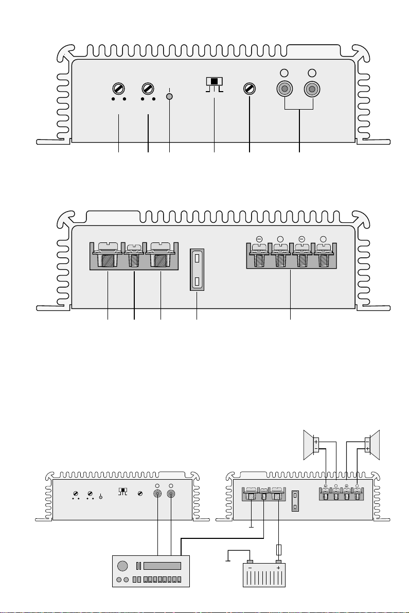
Bitte klappen Sie die Seite 3 heraus. Sie sehen
dann immer die beschriebenen Bedienelemente
und Anschlüsse.
1 Übersicht der Bedienelemente und An-
schlüsse
1 Trimmregler für die T rennfrequenz des Hochpasses
2 Trimmregler für die Trennfrequenz des Tiefpasses
3 Betriebsanzeige
4 Umschalter für den Betriebsmodus
HP/ST = Satellitenlautsprecherbetrieb
ST = Vollbereichslautsprecherbetrieb
LP/MO = Subwoofer-Betrieb
5 Regler zur Eingangspegelanpassung
6 Line-Eingänge (L/R)
7 Masseanschluß GND
8 Steuereingang RTM zum Einschaltender Car-HiFi-
Endstufe über eine 12-V-Spannung
9 Anschluß für die Versorgungsspannung +12V
10 Sicherung 25A
11 Lautsprecheranschlüsse
2 Sicherheitshinweise
Das Gerät entspricht der Richtlinie 89/ 336 /EWG für
elektromagnetische Verträglichkeit.
!
Beim Anschluß der Car-HiFi-Endstufe an die Autobatterie ist besondere Sorgfalt geboten. Bei Kurzschlüssen können sehr gefährlich hohe Ströme
fließen. Schrauben Sie deshalb unbedingt vor dem
Anschluß die Minusklemme der Autobatterie ab.
!
Die Endstufe muß fest und fachgerecht an einer
mechanisch stabilen Stelle im Auto montiert werden,
damit sie sich nicht löst und zu einem gefährlichen
Geschoß wird.
!
Während des Betriebs kann das Gerät sehr heiß
werden. Plazieren Sie darum keine hitzeempfindlichen Gegenstände in der Nähe, und berühren Sie
die Endstufe nicht während des Betriebs.
!
Verwenden Sie für die Reinigung nur ein trockenes,
weiches Tuch, auf keinen Fall Chemikalien oder
Wasser.
!
Wird das Gerät zweckentfremdet, falsch bedient,
nicht richtig angeschlossen oder nicht fachgerecht
repariert, kann für eventuelle Schäden keine Haftung übernommen werden.
!
Soll das Gerät endgültig aus dem Betrieb genommen werden, übergeben Sie es zur Entsorgung einem örtlichen Recyclingbetrieb.
3 Vorsicht bei hohen Lautstärken
!
Stellen Sie die Lautstärke nie sehr hoch ein. Extrem
hohe Lautstärken können das Gehör schädigen.
!
Das menschliche Ohr gewöhnt sich an große Lautstärken und empfindet sie nach einiger Zeit als nicht
mehr so hoch. Erhöhen Sie darum eine einmal eingestellte hohe Lautstärke nach der Gewöhnung
nicht weiter.
!
Während des Autofahrens dürfen Signaltöne, z. B.
von einem Rettungswagen, nicht durch eine zu große
Lautstärke der Car-HiFi-Anlage übertönt werden.
4 Einsatzmöglichkeiten
Die Endstufe HPB-250 ist speziell für Car-HiFi-Anlagen konzipiert. Mit ihr lassen sich zwei Vollbereichslautsprecher betreiben. Durch die integrierten
Frequenzweichen läßt sich eine bereits vorhandene
Anlage aber auch durch zwei Satellitenlautsprecher
oder zwei Baßlautsprecher bzw. einem Subwoofer ergänzen.
5 Montage
Bei der Auswahl des Montageplatzes unbedingt die
folgenden Punkte beachten:
!
Das 12-V-Stromversorgungskabel von der Batterie
zur Car-HiFi-Endstufe sollte so kurz wie möglich
sein. Es ist günstiger, längere Lautsprecherkabel zu
verwenden und dafür ein kürzeres Stromversorgungskabel.
!
Die Masseleitung von der Endstufe zum Fahrzeugchassis sollte ebenfalls so kurz wie möglich sein.
!
Um die entstehende Wärme der Car-HiFi-Endstufe
ableiten zu können, muß eine ausreichende Belüftung gewährleistet sein.
!
Wegen der beim Bremsen auftretenden Kräfte muß
die Endstufe an einer mechanisch stabilen Stelle angeschraubt werden.
!
Die Sicherung und die Regler müssen zugänglich
sein.
Zur Montage die vier Bohrungen am Kühlkörper verwenden. Die Car-HiFi-Endstufe an geeigneter Stelle
mit vier Schrauben fest montieren.
6 Anschlüsse
!
Der Anschluß der Car-HiFi-Endstufe an das Bordnetz darf nur durch qualifiziertes Fachpersonal erfolgen.
!
Um bei einem eventuellen Kurzschluß während der
Installation Schäden zu vermeiden, schrauben Sie
unbedingt vor dem Anschluß die Minusklemme der
Autobatterie ab.
!
Verlegen Sie die erforderlichen Kabel so, daß deren
Isolierung nicht beschädigt werden kann.
Der gesamte Anschluß ist in Abb.3 dargestellt.
6.1 Stromversorgung
6.1.1 Anschluß RMT (8)
Die Car-HiFi-Endstufe wird durch eine Steuerspannung
von +12V am Anschluß RMT ein- und ausgeschaltet.
Den Anschluß RMTmit dem 12-V-Ausgang vom Autoradio verbinden (Anschluß für eine Motorantenne,
eventuell mit der Motorantenne parallelschalten).
Wenn kein 12-V-Ausgang am Autoradio vorhanden
ist, muß der Anschluß RMT +12 V über das Zündschloß oder über einen separaten Schalter erhalten.
D
A
CH
4
Page 5

6.1.2 Anschluß +12V (9)
Den Anschluß +12 V über ein Kabel mit einem Querschnitt von mindestens 10mm
2
(z.B. CPC-100/RTvon
CARPOWER) mit der Plusklemme der Autobatterie
verbinden. Um die neu verlegte 12-V-Leitung gegen einen Kurzschluß abzusichern, unbedingt eine 25-A-Vorsicherung in unmittelbarer Nähe der Batterie zwischensetzen (Abb.3).
Zur Stabilisierung der Betriebsspannung für die
Endstufe und der damit verbundenen Leistungssteigerung sowie Klangverbesserung wird ein Power-Kondensator empfohlen (z. B. CPS-500 oder CPS-1000
von CARPOWER).
6.1.3 Anschluß GND (7)
Den Masseanschluß GND über ein Kabel mit einem
Querschnitt von mindestens 10mm
2
(z.B. CPC100/SW von CARPOWER) mit der Masse des Autos
oder direkt mit der Minusklemme der Autobatterie verbinden. Zur Vermeidung von Masseschleifen muß die
Masse des Autoradios an die Stelle gelegt werden, an
der auch die Endstufe an Masse liegt.
6.2 Eingänge
Die beiden Eingänge INPUT (6) über Cinch-Kabel mit
den entsprechenden Line-Ausgängen am Autoradio
verbinden. Sind am Autoradio keine Line-Ausgänge
vorhanden, alternativ die Lautsprecherausgänge des
Autoradios über einen entsprechenden Übertrager
(z. B. FGA-20 von CARPOWER) mit den Eingängen
der Endstufe verbinden.
6.3 Lautsprecher
Es können Vollbereichs-, Satelliten- oder Baßlautsprecher bzw. ein Subwoofer betrieben werden. Die größte
Ausgangsleistung wird beim Anschluß von 2-Ω-Laut-
sprechern oder einer Lautsprechergruppe mit einer
Gesamtimpedanz von 2Ω pro Kanal erreicht (z. B.
zwei 4-Ω-Lautsprecher oder vier 8-Ω-Lautsprecher
parallelgeschaltet). Es können jedoch auch einzelne
4-Ω- oder 8-Ω-Lautsprecher angeschlossen werden,
wobei sich die Ausgangsleistung verringert.
Wichtig! Alle Lautsprecher müssen 2polig ange-
schlossen werden, d.h. ohne gemeinsamen Masseanschluß.
Bei der Auswahl geeigneter Lautsprecher
unbedingt deren mechanische und elektrische Belastbarkeit im Zusammenhang mit
der genutzten Endstufenleistung berücksichtigen (siehe auch technische Daten der
Endstufe Seite 6).
6.3.1 Baßlautsprecher oder Subwoofer
Da sich die tiefen Töne vom menschlichen Ohr nicht
räumlich orten lassen, arbeiten Subwoofer im MonoBetrieb. Für den Betrieb mit Baßlautsprechern bzw.
einem Subwoofer den Schiebeschalter (4) in die Position LP/MO stellen.
Anschlüsse der Lautsprecher an den Klemmen
SPEAKER (11):
L+ = + linker Baßlautsprecher bzw. + Subwoofer*
L
-
= -linker Baßlautsprecher bzw. -Subwoofer*
R+ = + rechter Baßlautsprecher
R
-
= -rechter Baßlautsprecher
*Durch die unterschiedlichen Laufzeiten der Schallwellen
vom Subwoofer und von den übrigen Lautsprechern zum
Hörplatz kann es erforderlich sein, den Subwoofer umzupolen, d.h. die Plus- und Minusanschlüsse zu vertauschen.
Mit dem Regler LP (2) die Trennfrequenz für die
Baßlautsprecher bzw. für den Subwoofer im Bereich
30–350Hz einstellen (je niedriger die obere Grenzfrequenz, desto schwerer die akustische Ortung eines
Subwoofers; je höher die Grenzfrequenz, desto stärker die Baßunterstützung). Zur Orientierung die technischen Daten der eingesetzen Lautsprecher beachten.
6.3.2 Vollbereichslautsprecher
Für den Betrieb mit Vollbereichslautsprechern den
Schiebeschalter (4) in die Position ST stellen, und die
Lautsprecher an die Klemmen SPEAKER (11) anschließen:
L+ = + linker Lautsprecher
L
-
= -linker Lautsprecher
R+ = + rechter Lautsprecher
R
-
= -rechter Lautsprecher
6.3.3 Satellitenlautsprecher
Für dem Betrieb mit Satellitenlautsprechern den
Schiebeschalter (4) in die Position HP/ST stellen, und
die Lautsprecher an die Klemmen SPEAKER (11) anschließen:
L+ = + linker Lautsprecher
L
-
= -linker Lautsprecher
R+ = + rechter Lautsprecher
R
-
= -rechter Lautsprecher
Mit dem Regler HP (1) die Trennfrequenz für die Satel-
litenlautsprecher im Bereich 30–350Hz einstellen. Es
sollte ca. der gleiche Wert wie für den Subwoofer eingestellt werden. Bei einer zu hohen Trennfrequenz
kommt es sonst in einem bestimmten Frequenzbereich zu einem Pegeleinbruch bzw. bei einer zu
niedrigen Trennfrequenz im Bereich der Überschneidung von Subwoofer und Satellitenlautsprechern zu
einer Pegelüberhöhung. In beiden Fällen entsteht eine
Klangverfärbung.
7 Pegelanpassung
Vor dem Einschalten sollte die komplette Verdrahtung der Car-HiFi-Endstufe noch einmal auf Richtigkeit überprüft werden. Erst danach die Minusklemme der Autobatterie wieder anschließen.
Tip: Um Störeinstrahlungen durch die Autoelektrik so
gering wie möglich zu halten, sollte der Ausgangspegel der Signalquelle min. 1,5V betragen.
1) Den Regler INPUT LEVEL (5) entgegen dem Uhr-
zeigersinn auf Minimum stellen.
2) Die Signalquelle, z. B. das Autoradio, auf maximale,
nicht verzerrende Lautstärke einstellen (meistens
ca.
3
/4 vom Maximum).
3) Den Regler INPUT LEVEL (5) so weit aufdrehen,
daß gerade keine Verzerrungen auftreten.
4) Wird die Endstufe zur Erweiterung der vorhande-
nen Car-HiFi-Anlage eingesetzt, zur Anpassung der
D
A
CH
5
Page 6

Lautstärke aller Kanäle untereinander die jeweils zu
lauten Kanäle im Pegel reduzieren. (Sollte dann die
Gesamtlautstärke den gewünschten Pegel nicht erreichen, in die zu schwachen Kanäle kräftigere
Endstufen einsetzen.)
8 Fehlerbeseitigung
Ist nach dem Einschalten der Car-HiFi-Anlage kein
Ton zu hören, den Fehler mit Hilfe der roten LED
POWER (3) für die Betriebsanzeige näher lokalisieren.
8.1 LED leuchtet nicht
1) Die Sicherung (10) an der Car-HiFi-Endstufe (25 A)
und die Vorsicherung an der Autobatterie (25A)
überprüfen. Defekte Sicherungen auswechseln.
Nur Sicherungen mit den angegebenen Werten
verwenden. Auf keinen Fall einen höheren Wert
einsetzen. Die Endstufe kann beschädigt werden,
und die Garantie erlischt.
2) Das 12-V-Stromversorgungskabel sowie das Massekabel auf korrekten Anschluß und Unterbrechung
kontrollieren.
3) An der Anschlußklemme RMT (8) der Car-HiFiEndstufe messen, ob +12V anliegt. Wenn nicht, die
Leitung an der Klemme RMT entfernen und kurzzeitig die Klemmen RMT (8) und +12 V (9) überbrücken. Schaltet die Car-HiFi-Endstufe jetzt ein,
liegt der Fehler in der fehlenden Steuerspannung.
Den 12-V-Ausgang des Autoradios (bzw. den separaten Schalter oder das Zündschloß) und das
entsprechende Anschlußkabel zur Endstufe überprüfen.
4) Die Endstufe ist mit einer Schutzschaltung gegen
Überlast und Kurzschluß an den Lautsprecherausgängen sowie gegen Überhitzung (85°C) gesichert.
Spricht die Schutzschaltung an, erlischt die LED
POWER. Nach der Fehlerbeseitigung oder nach
dem Abkühlen schaltet die Endstufe automatisch
wieder ein.
Bei sich wiederholendem Ein- und Ausschalten
die Lautsprecherkabel auf Kurzschluß und die Lautsprecher auf ihre Impedanz überprüfen (min. 2 Ω
pro Kanal). Die Ursache kann auch an einer nicht
ausreichenden Wärmeableitung (Belüftung) liegen.
8.2 LED leuchtet
1) Die Verbindungskabel von der Signalquelle zur
Car-HiFi-Endstufe überprüfen. Sind die Stecker
richtig eingesteckt? Ist die Leitung unterbrochen?
2) Die Signalquelle überprüfen. Ist die Signalquelle
eingeschaltet? Sind die richtigen Ausgänge verwendet worden? Ist die Signalquelle defekt?
3) Die Lautsprecherkabel auf Unterbrechung überprüfen.
9 Technische Daten
Max. Ausgangsleistung: . . 2 x 100W an 4Ω
Ausgangsleistung Sinus: . . 2 x 80W an 2Ω
2 x 50W an 4Ω
2 x 30W an 8Ω
Frequenzbereich: . . . . . . . 20 – 20 000 Hz
Eingänge, 2 x Line: . . . . . . einstellbar von 0,3 bis 5V
Trennfrequenz
Tiefpaß: . . . . . . . . . . . . . 30 – 350 Hz; 12 dB/Okt.
Hochpaß: . . . . . . . . . . . 30–350Hz; 12dB/Okt.
Kanaltrennung: . . . . . . . . . > 60dB
Störabstand: . . . . . . . . . . . > 90dB
Klirrfaktor: . . . . . . . . . . . . . < 0,1 %
Eingangsimpedanz: . . . . . 10 kΩ
Ausgangsimpedanz: . . . . . 2 x 2 Ω
Stromversorgung
(Chassis Minus): . . . . . . . . 11–16V , max. 25A
Einsatztemperatur: . . . . . . 0–40°C
Abmessungen: . . . . . . . . . 260 x 183 x 53 mm
Gewicht: . . . . . . . . . . . . . . 2,6 kg
Laut Angaben des Herstellers.
Änderungen vorbehalten.
D
A
CH
6
Page 7

Please unfold page3. Then you can always see the
operating elements and connections described.
1 Operating Elements and Connections
1 Trimming control for the crossover frequency of the
high pass
2 Trimming control for the crossover frequency of the
low pass
3 POWER indication
4 Selector switch for the operating mode
HP/ST = satellite speaker operation
ST = full range speaker operation
LP/MO = subwoofer operation
5 Control for input level matching
6 Line inputs (L/R)
7 Ground terminal GND
8 Control input RTM for switching on the car HiFi
booster via a 12V voltage
9 Connection for the supply voltage +12V
10 Fuse 25A
11 Speaker terminals
2 Safety Notes
The unit corresponds to the directive 89/336/EEC for
electromagnetic compatibility.
!
When connecting the car HiFi booster to the car battery, be especially careful. In case of short circuits
there may be very dangerously high currents. Therefore, prior to the connection it is absolutely necessary to screw off the negative terminal of the car battery.
!
The booster must be mounted to a mechanically
stable place in the car. It must be skilfully fixed so
that it does not get loose and turn into a dangerous
projectile.
!
During operation the booster can become very hot.
Therefore, do not place any objects sensitive to heat
near the booster and do not touch it while in operation.
!
For cleaning only use a dry, soft cloth, by no means
chemicals or water.
!
If the booster is used for purposes other than originally intended, if it is not correctly operated or
connected or not repaired by authorized personnel,
no liability can be taken over for any possible
damage.
!
If the unit is to be put out of operation definitively, it
must be disposed of in a local recycling plant.
3 Caution in Case of High Volumes
!
Never adjust the volume very high. Extremely high
volumes may damage the hearing.
!
The human ear gets accustomed to high volumes
which do not seem to be so high any more after
some time. Therefore, do not increase a high volume
which has once been adjusted after getting used to it.
!
While driving in the car, signal sounds, e. g. by an
ambulance, must not be drowned by the volume of
the car HiFi system adjusted too high.
4 Applications
The booster HPB-250 has especially been designed
for car HiFi systems. Two full range speakers can be
operated with this booster. Due to the integrated crossover networks, an existing system can also be completed by two satellite speakers or two bass speakers
resp. a subwoofer.
5 Mounting
When choosing the place of mounting, always observe
the following items in any case:
!
The 12V power supply cable from the battery to the
car HiFi booster should be as short as possible. It is
more advantageous to use longer speaker cables
and a shorter power supply cable instead.
!
The ground cable from the booster to the chassis of
the car should also be as short as possible.
!
For carrying off the heat being generated in the
booster, a sufficient ventilation has to be ensured.
!
Because of the forces occurring during braking, the
booster must be screwed to a mechanically stable
place.
!
The fuse and the controls must be accessible.
For mounting use the four drill holes at the heat sink.
Firmly mount the car HiFi booster to a suitable place
with four screws.
6 Connections
!
The connection of the car HiFi booster to the electric
system of the car must only be carried out by authorized personnel.
!
T o prevent damage in case of a possible short circuit
during installation, prior to connection it is absolutely
necessary to screw off the negative terminal of the
car battery.
!
Lay the necessary cables so that their insulation
cannot be damaged.
The complete connection is shown in fig. 3.
6.1 Power supply
6.1.1 Terminal RMT (8)
The car HiFi booster is switched on and off by a +12V
control voltage at the terminal RMT . Connect the terminal RMT to the 12 V output of the car radio (connection
for a motor antenna, if necessary to be connected in
parallel with the motor antenna).
If no 12 V output is provided at the car radio, the
terminal RMT must get +12V via the ignition lock or a
separate switch.
6.1.2 Terminal +12V (9)
Connect the terminal +12 V via a cable with a cross
section of min. 10 mm
2
(e. g CPC-100/ RT by CAR-
POWER) to the positive terminal of the car battery. To
GB
7
Page 8

GB
8
protect the newly laid 12V cable against short circuit,
insert in any case an additional 25A fuse very near to
the battery (fig. 3).
To stabilize the operating voltage for the booster
and the resulting power increase as well as sound improvement, a power capacitor is recommended (e. g.
CPS-500 or CPS-1000 by CARPOWER).
6.1.3 Terminal GND (7)
Connect the ground terminal GND via a cable of a
cross section of min. 10 mm
2
(e. g. CPC-100 /SW by
CARPOWER) to the ground of the car or directly to the
negative terminal of the car battery. To avoid ground
loops, the ground of the car radio must be placed at the
point where also the booster is grounded.
6.2 Inputs
Connect both inputs INPUT (6) via cables with phono
connectors to the corresponding line outputs of the car
radio. If no line outputs are provided on the car radio,
alternatively connect the speaker outputs of the car
radio via a corresponding transformer (e.g. FGA-20 by
CARPOWER) to the booster inputs.
6.3 Speakers
Full range speakers, satellite speakers or bass
speakers resp. a subwoofer can be used. The greatest
output power is obtained with the connection of 2 Ω
speakers or a speaker group with a total impedance of
2Ω per channel (e. g. two 4 Ω speakers or four 8 Ω
speakers connected in parallel). However, individual
4Ω or 8 Ω speakers may also be connected whereby
the output power is reduced.
Important! All speakers must be connected with
2 poles, i.e. without common ground
connection.
When choosing suitable speakers, pay in
any case attention to their mechanical
and electrical capability in connection
with the booster power applied (also see
specifications of the booster page 9).
6.3.1 Bass speakers or subwoofer
As the low frequencies cannot be located by the human ear, subwoofers operate in mono operation. For
the operation with bass speakers or a subwoofer, set
the sliding switch (4) to position LP/MO.
Connections of the speakers to the terminals
SPEAKER (11):
L+ = + left bass speaker or + subwoofer*
L
-
= -left bass speaker or -subwoofer*
R+ = + right bass speaker
R
-
= -right bass speaker
* Due to the different delay times of the sound waves from
the subwoofer and from the remaining speakers to the
place of hearing it may be necessary to change the polarity
of the subwoofer, i.e. to reverse the positive and the negative connections.
Adjust with the control LP (2) the crossover frequency
for the bass speakers or for the subwoofer in the range
30 – 350 Hz (the lower the upper limit frequency, the
more difficult the acoustic location of a subwoofer; the
higher the limit frequency, the more powerful the bass
support). As a guidance observe the specifications of
the speakers used.
6.3.2 Full range speakers
For the operation with full range speakers set the
sliding switch (4) to position ST, and connect the
speakers to the terminals SPEAKER (11):
L+ = + left speaker
L
-
= -left speaker
R+ = + right speaker
R
-
= -right speaker
6.3.3 Satellite speakers
For the operation with satellite speakers set the sliding
switch (4) to position HP/ST, and connect the speakers
to the terminals SPEAKER (11):
L+ = + left speaker
L
-
= -left speaker
R+ = + right speaker
R
-
= -right speaker
With the control HP (1) adjust the crossover frequency
for the satellite speakers in the range 30–350Hz.
Approx. the same value as for the subwoofer should
be adjusted. Otherwise, if the crossover frequency is
too high, the level will fall in a certain frequency range,
or if the crossover frequency is too low, the level will
increase too much in the overlapping range of subwoofer and satellite speakers. In both cases there will
be a sound discolouration.
7 Level Matching
Prior to switching on, the complete wiring of the car
HiFi booster should be checked once again for correct connection. Only then connect the negative terminal of the car battery again.
Hint: To keep the interfering radiation by the electric
system of the car as low as possible, the output
level of the signal source should be min. 1.5V.
1) Set the control INPUT LEVEL (5) counter-clockwise
to minimum.
2) Adjust the signal source, e. g. the car radio, to the
max. volume which is not distorted (mainly to approx.
3
/4 of the maximum).
3) Turn up the control INPUT LEVEL (5) so that just no
distortions occur.
4) If the booster is used for the extension of the exist-
ing car HiFi system, reduce the levels of the channels which are too high to match the volumes of all
channels with each other. (In case the total volume
should not reach the desired level, insert more
powerful boosters into the channels which are too
poor.)
Page 9

8 Trouble Shooting
If there is no sound after switching on the car HiFi system, locate the fault more precisely by means of the
red LED POWER (3) for operating indication.
8.1 LED does not light up
1) Check the fuse (10) on the car HiFi booster (25 A)
and the additional fuse on the car battery (25 A).
Replace defective fuses. Only use fuses with the
values as indicated. Do not insert fuses with a
higher value under any circumstances. The booster
can be damaged, and the guarantee will be cancelled.
2) Check the 12 V power supply cable as well as the
ground cable for correct connection and interruption.
3) Check if +12 V is present at the terminal RMT (8) of
the car HiFi booster. If not, remove the cable at the
terminal RMT and bridge the terminals RMT (8) and
+12 V (9) for a short time. If the car HiFi booster
switches on now, the error is due to the missing
control voltage. Check the 12 V output of the car
radio (or the separate switch or the ignition lock)
and the corresponding cable to the booster.
4) The booster is protected at the speaker outputs with
a protection circuit against overload and short circuit as well as against overheating (85 °C). If the
protection circuit responds, the LED POWER extinguishes. After the error has been eliminated or after
cooling-down, the booster automatically switches
on again.
In case of repeated switching on and off, check
the speaker cables for short circuit and the impedance of the speakers (min. 2 Ω per channel). This
may also due to the fact that the heat dissipation
(ventilation) is not sufficient.
8.2 LED lights up
1) Check the connection cable from the signal source
to the car HiFi booster. Are the plugs correctly
connected? Is the cable interrupted?
2) Check the signal source. Is the signal source
switched on? Have the correct outputs been used?
Is the signal source defective?
3) Check the speaker cables for interruption.
9 Specifications
Max. output power: . . . . . . 2 x 100 W at 4 Ω
Output power rms: . . . . . . 2 x 80 W at 2 Ω
2 x 50W at 4Ω
2 x 30W at 8Ω
Frequency range: . . . . . . . 20–20000Hz
Inputs, 2 x line: . . . . . . . . . adjustable from
0.3 up to 5V
Crossover frequency
Low pass: . . . . . . . . . . . 30 – 350 Hz; 12 dB/oct.
High pass: . . . . . . . . . . . 30 – 350 Hz; 12 dB/oct.
Channel separation: . . . . . > 60dB
S/N ratio: . . . . . . . . . . . . . > 90dB
THD: . . . . . . . . . . . . . . . . . < 0.1 %
Input impedance: . . . . . . . 10 kΩ
Output impedance: . . . . . . 2 x 2Ω
Power supply
(chassis minus): . . . . . . . . 11–16V , max. 25A
Ambient temperature: . . . . 0 – 40 °C
Dimensions: . . . . . . . . . . . 260 x 183 x 53mm
Weight: . . . . . . . . . . . . . . . 2.6kg
According to the manufacturer.
Subject to change.
GB
9
Page 10

Ouvrez le présent livret page 3 de manière à visualiser les éléments et branchements.
1 Eléments et branchements
1 Réglage de la fréquence de coupure du passe-
haut
2 Réglage de la fréquence de coupure du passe-bas
3 Témoin de fonctionnement
4 Sélecteur du mode de fonctionnement
HP/ST = mode satellite
ST = mode large bande
LP/MO = mode subwoofer
5 Potentiomètre de réglage pour l’adaptation de ni-
veau
6 Entrées Ligne (D/G)
7 Branchement masse GND
8 Entrée commande RTM pour allumer l’amplifica-
teur pour HiFi embarquée via une tension 12V
9 Connexion pour la tension d’alimentation +12V
10 Fusible 25A
11 Connexions haut-parleurs
2 Conseils d’utilisation
Cet amplificateur répond à la norme européenne 89/
336/CEE relative à la compatibilité électromagnétique.
!
Lorsque vous reliez l’amplificateur pour HiFi embarquée à la batterie de la voiture, soyez très prudent;
en cas de court-circuit, des courants très élevés et
donc dangereux circulent. C’est pourquoi avant tout
branchement, n’oubliez pas de dévisser la borne
moins de la batterie de la voiture.
!
L’appareil doit être solidement fixé dans un endroit
méchaniquement stable pour éviter qu’il ne se
dévisse et ne se transforme en projectile dangereux.
!
Pendant son fonctionnement, il peut devenir très
chaud; il est recommandé de ne pas placer à proximité d’objets sensibles à la chaleur et de ne pas le
toucher pendant son fonctionnement.
!
Pour le nettoyer, utilisez un chiffon sec et doux, en
aucun cas de produits chimiques ou d’eau.
!
Nous déclinons toute responsabilité en cas de dommage si l’appareil est utilisé dans un but autre que
celui pour lequel il a été conçu, s’il n’est pas correctement utilisé ou branché ou s’il n’est pas réparé par
un technicien qualifié.
!
Lorsque l’appareil est définitivement retiré du circuit
de distribution, vous devez le déposer dans une
usine de recyclage adaptée.
3 Attention: Volumes élevés
!
Ne réglez jamais le volume trop fort. Des volumes
trop élevés peuvent endommager l’ouïe.
!
L’oreille humaine s’habitue à des volumes élevés et,
après un certain temps, ne les perçoit plus de la
même manière. C’est pourquoi nous vous recommandons de ne pas augmenter le volume une fois
que vous y êtes habitué.
!
Ne réglez jamais le volume du système audio trop
fort: vous devez pouvoir toujours entendre les bruits
extérieurs, par exemple, une ambulance.
4 Utilisations
L’amplificateur HPB-250 est spécialement conçu pour
la HiFi embarquée. Il permet de faire fonctionner deux
haut-parleurs de large bande; les filtres intégrés permettent de compléter une installation déjà existante
avec deux haut-parleurs satellite ou deux haut-parleurs de grave ou un subwoofer.
5 Montage
Lorsque vous choisissez le lieu d’installation de l’appareil, respectez en tous cas les points suivants:
!
Le cordon d’alimentation de 12V reliant la batterie à
l’amplificateur devrait être aussi court que possible;
il est préférable d’utiliser des câbles haut-parleurs
plus longs et par contre un cordon d’alimentation
plus court.
!
Le câble de la masse reliant l’amplificateur au châssis du véhicule devrait être aussi court que possible.
!
Pour permettre une évacuation correcte de la chaleur dégagée par l’amplificateur, veillez à assurer
une ventilation suffisante.
!
A cause des forces qui résultent lors du freinage, il
peut se transformer en projectile dangereux, veillez
à le fixer correctement à un endroit mécaniquement
stable.
!
Le fusible et les composants doivent être faciles
d’accès.
Pour le montage user les 4 trous de fixation prévus sur
le dissipateur. Montez-le à l’endroit appropié en fixant
les 4 vis livrées.
6 Branchements
!
Le branchement de l’amplificateur au systém électrique de la voiture ne doit être effectué que par un
technicien habilité.
!
Pour éviter tout court-circuit éventuel lors de l’installation, et ainsi tout dégât, dévissez impérativement
la borne moins de la batterie de la voiture.
!
Placez les câbles de telle sorte que leur isolation ne
soit pas endommagée.
Le schéma 3 présente l’ensemble des branchements.
6.1 Alimentation
6.1.1 Branchement RMT (8)
L’amplificateur est allumé/ éteint par une tension en
+12 V à la borne RMT. Reliez la borne RMT à la sortie
12 V de l’autoradio (branchement pour une antenne de
moteur, éventuellement branché en parallèle à l’antenne de moteur).
Si l’autoradio n’a pas de sortie 12V , vous devez appliquer une tension +12V à la borne RMT à partir de la
clé de contact ou d’un interrupteur séparé.
F
B
CH
10
Page 11

6.1.2 Branchement +12 V (9)
Le branchement +12V à la borne Plus de la batterie doit
être effectué avec un câble d’une section de 10mm
2
au
moins (p.ex. CPC-100/RT de CARPOWER); pour
protéger le nouveau câble 12V contre tout court-circuit,
vous devez impérativement insérer un fusible 25Asupplémentaire à proximité immédiate de la batterie
(schéma 3).
Pour stabiliser la tension de fonctionnement pour
l’amplificateur et l’augmentation de puissance relié
ainsi que la meilleure restitution sonore, il est recommandé d’utiliser un condensateur de puissance (p.ex.
CPS-1000 ou CPS-500 de CARPOWER).
6.1.3 Branchements GND (7)
Avec un câble d’une section de 10mm
2
au moins
(p.ex. CPC-100/SW de CARPOWER), reliez la borne
de masse GND à la masse du véhicule ou directement
à la borne Moins de la batterie de la voiture. Pour éviter
tout bouclage de masse, la masse de l’autoradio doit
être placée là où la masse de l’amplificateur est située.
6.2 Entrées
Reliez les deux entrées INPUT (6) avec des cordons
RCA aux sorties Ligne correspondantes de l’autoradio.
Si l’autoradio n’a pas de sorties Ligne, vous pouvez relier les sorties haut-parleurs de l’autoradio alternativement aux entrées de l’amplificateur avec un transformateur correspondant (p.ex. FGA-20 de CARPOWER).
6.3 Haut-parleurs
Il est possible d’utiliser des haut-parleurs large bande,
satellite, graves ou un subwoofer. La puissance de
sortie est maximale lorsqu’on branche des haut-parleurs en 2Ω ou un groupe de haut-parleurs avec une
impédance totale de 2Ω par canal (p. ex. 2 haut-parleurs 4 Ω ou 4 haut-parleurs 8 Ω branchés en parallèle). Il est possible de brancher des haut-parleurs individuels de 4 Ω ou 8 Ω, la puissance de sortie est
alors diminuée.
Important: Tous les haut-parleurs doivent être bran-
chés avec 2 pôles, c’est-à-dire sans con-
nexion de masse commune.
Lors de la sélection des haut-parleurs appropiés, veillez à prendre en compte la capacité mécanique et électrique du haut-parleur selon la puissance appliquée de l’amplificateur (voir aussi les charactéristiques
techniques de l’amplificateur, page 12).
6.3.1 Haut-parleurs de grave ou subwoofer
Dans la mesure où les sons graves ne peuvent pas
être localisés par l’oreille humaine, le subwoofer travaille en mode mono. Pour le fonctionnement avec des
haut-parleurs de grave ou un subwoofer, mettez le
sélecteur (4) sur la position LP/MO.
Branchements des haut-parleurs aux bornes SPEAKER
(11):
L+ = + HP grave gauche ou + subwoofer*
L
-=-
HP grave gauche ou – subwoofer*
R+ = + HP grave droit
R
-=-
HP grave droit
*De par les différentes durées d’ondulation du subwoofer et
des autres haut-parleurs vers le lieu d’écoute, il peut être
nécessaire de modifier la polarité du subwoofer, c’est-à-dire
d’inverser les branchements plus et moins.
Avec le réglage LP(2), réglez la fréquence de coupure
pour les haut-parleurs de grave ou le subwoofer dans
la plage 30 – 350 Hz (plus la fréquence limite supérieure est faible, plus la localisation acoustique d’un
subwoofer est ardue; plus la fréquence limite des élevée, plus la part des graves est importante). Observer
les charactéristiques techniques pour les haut-parleurs utilisés.
6.3.2 Haut-parleurs large bande
Dans ce cas, mettez le sélecteur (4) sur la position ST,
reliez les haut-parleurs aux bornes SPEAKER (11):
L+ = + HP gauche
L
-=-
HP gauche
R+ = + HP droit
R
-=-
HP droit
6.3.3 Haut-parleurs satellite
Mettez le sélecteur (4) sur la position HP/ST et reliez
les haut-parleurs aux bornes SPEAKER (11):
L+ = + HP gauche
L
-=-
HP gauche
R+ = + HP droit
R
-
=-HP droit
Avec le réglage HP(1), réglez la fréquence de coupure
pour les haut-parleurs satellite dans la plage
30– 350 Hz. La valeur devrait être quasi-identique à
celle du subwoofer. Si la fréquence de coupure est trop
élevée, dans une bande de fréquence donnée, le niveau chute; pour une fréquence de coupure trop faible,
le niveau va trop augmenter dans la partie qui se chevauche du subwoofer et des haut-parleurs satellites;
dans les deux cas, il y aura décoloration du son.
7 Adaptation de niveaux
Avant d’allumer l’amplificateur, le câblage complet
de l’amplificateur doit être vérifié. Seulement après
reliez la borne Moins de la batterie de la voiture de
nouveau.
Astuce: pour minimiser les risques d’interférences
électriques dues au système électrique du
véhicule, le niveau de sortie de la source devrait être de 1,5V au moins.
1) Tournez le réglage INPUT LEVEL (5) vers le mini-
mum dans le sens inverse des aiguilles d’une montre.
2) Réglez la source, par exemple l’autoradio, sur le
volume maximal n’entraînant pas de distorsion
(généralement
3
/4 env. du maximum).
3) Tournez le réglage INPUTLEVEL (5) jusqu’au point
où des distorsions ne résultent pas encore.
4) Si l’amplificateur est utilisé comme extension de
l’installation HiFi existante, pour adapter le volume
de tous les canaux entre eux, réduisez le niveau
des canaux trop forts (si le volume général ne devrait pas atteindre le niveau souhaité, insérez dans
les canaux trop faibles des amplificateurs plus puissants).
F
B
CH
11
Page 12

8 Eliminer des problèmes
Si lors de l’allumage de l’installation, aucun son n’est
audible, la LED rouge POWER (3) témoin de fonctionnement peut vous aider à localiser le problème.
8.1 La LED ne brille pas
1) Vérifiez le fusible (10) sur l’amplificateur (25 A) et le
fusible supplémentaire de la batterie de la voiture
(25 A). Remplacez tout fusible défectueux. N’utilisez que des fusibles avec les valeurs indiquées, en
aucun cas de valeur supérieure. L’amplificateur
peut être endommagé, dans ce cas, la garantie devient caduque.
2) Contrôlez le cordon d’alimentation 12 V et le câble
masse; vérifiez les connexions et la solidité du
câble.
3) Mesurez si la tension +12 V est bien présente à la
borne RMT (8) de l’amplificateur. Si ce n’est pas le
cas, retirez le câble de la borne RMT et bridgez
brièvement les bornes RMT(8) et +12V (9). Si l’amplificateur s’allume maintenant, le problème réside
dans l’absence de tension d’alimentation: vérifiez la
sortie 12 V de l’autoradio (ou l’interrupteur séparé
ou la clé) et le cordon de liaison correspondant à
l’amplificateur.
4) Aux sorties haut-parleurs, l’amplificateur est
protégé avec un circuit de protection, de toute
surcharge, court-circuit et surchauffes (85°C). Si le
circuit de protection répond, la LED POWER s’éteint; une fois le problème résolu et l’amplificateur
refroidi, l’amplificateur redémarre automatiquement.
En cas d’arrêt et redémarrage répétés, vérifiez
les câbles haut-parleurs s’il y a des courts-circuits,
et vérifiez l’impédance des haut-parleurs (2Ω mini-
mum par canal). La cause peut également résider
dans un refroidissement insuffisant (ventilation) de
l’appareil.
8.2 La LED brille
1) Vérifiez le câble de liaison entre l’amplificateur et la
source. Les fiches sont-elles bien insérées? Le
câble est-il interrompu?
2) Vérifiez la source. La source est-elle allumée? Les
sorties sont-elles correctement utilisées? La source
est-elle défectueuse?
3) Vérifiez si les câbles haut-parleur ne présentent
pas de défaut.
9 Caractéristiques techniques
Puissance de sortie
maximale: . . . . . . . . . . . . . 2 x 100 W/4Ω
Puissance de sortie RMS: . 2 x 80 W/2Ω
2 x 50W/4 Ω
2 x 30W/8 Ω
Bande passante: . . . . . . . . 20–20 000 Hz
Entrées, 2 x Ligne: . . . . . . réglable de 0,3 à 5 V
Fréquence de coupure
Passe-bas: . . . . . . . . . . 30–350Hz, 12dB/oct.
Passe-haut: . . . . . . . . . . 30–350 Hz, 12 dB/oct.
Séparation des canaux: . . > 60 dB
Rapport signal/bruit: . . . . . > 90dB
Taux de distorsion: . . . . . . < 0,1%
Impédance d’entrée: . . . . . 10kΩ
Impédance de sortie: . . . . 2 x 2 Ω
Alimentation
(moins au châssis): . . . . . . 11–16V , 25 A max.
Température d’utilisation: . 0 – 40 °C
Dimensions: . . . . . . . . . . . 260 x 183 x 53mm
Poids: . . . . . . . . . . . . . . . . 2,6 kg
D’après les données du constructeur.
Tout droit de modification réservé.
F
B
CH
12
Page 13

Vi preghiamo di aprire completamente la pagina 3.
Così vedrete sempre gli elementi di comando e i
collegamenti descritti.
1 Elementi di comando e collegamenti
1 Potenziometro per la frequenza di taglio del filtro
passaalto
2 Potenziometro per la frequenza di taglio del filtro
passabasso
3 Spia di funzionamento
4 Commutatore per il modo d’esercizio
HP/ST = altoparlanti satellite
ST = altoparlanti che coprono tutta la gamma
sonora
LP/MO = subwoofer
5 Regolatore per adattamento livello
6 Ingressi Line (L/R)
7 Massa (GND)
8 Ingresso RTM per attivare il booster mediante una
tensione di 12V
9 Collegamento tensione +12V
10 Fusibile 25A
11 Collegamenti degli altoparlanti
2 Avvertenza di sicurezza
Quest’apparecchio corrisponde alla direttiva CE 89/
336/CEE sulla compatibilità elettromagnetica.
!
Usare particolare cura nel collegamento con la batteria dell’auto. Nel caso di cortocircuiti ci possono
essere delle correnti molto alte. Prima del collegamento scollegare il polo negativo della batteria.
!
Prevedere un posto solido e montare il booster con
cura per evitare che si possa staccare, diventando
pericoloso in caso di incidente.
!
Durante il funzionamento, il booster può riscaldarsi
molto. Non mettere nelle sue vicinanze oggetti sensibili al calore e non toccare il booster.
!
Per la pulizia usare solo un panno asciutto e morbido; non impiegare in nessun caso prodotti chimici
o acqua.
!
Nel caso di uso improprio, di collegamenti sbagliati o
di riparazione scorretta non si assume nessuna responsabilità per eventuali danni.
!
Se si desidera eliminare l’apparecchio definitivamente, consegnarlo per lo smaltimento ad un’istituzione locale per il riciclaggio.
3 Attenzione col volume alto
!
Non alzare troppo il volume. Il volume troppo alto
può danneggiare l’udito.
!
L’orecchio si abitua al volume alto e dopo un certo
periodo non se ne accorge più. Pertanto conviene
non aumentare il volume alto impostato inizialmente.
!
Mentre si guida l’auto, i segnali di ambulanze ecc.
non devono essere coperti dal volume dell’impianto
audio.
4 Possibilità d’impiego
Il booster HPB-250 è previsto per impianti hifi nelle
auto e può pilotare due altoparlanti a gamma sonora
completa. Grazie ai crossover integrati, l’impianto già
esistente può essere integrato con due altoparlanti satelliti oppure con due woofer o un subwoofer.
5 Montaggio
Prima di scegliere un posto per il montaggio occorre
considerare i seguenti punti:
!
Il cavo di alimentazione 12V dalla batteria al booster
deve essere il più corto possibile. E’preferibile usare
lunghi cavi per gli altoparlanti e tenere corto il cavo di
alimentazione.
!
Anche il cavo della massa dal booster al telaio della
macchina deve essere il più corto possibile.
!
Per poter dissipare il calore sprigionato dal booster
deve essere garantita una ventilazione sufficiente.
!
Per le forze che si manifestano nelle frenate, il punto
di montaggio deve essere meccanicamente stabile.
!
Il fusibile e i regolatori devono essere accessibili.
Per il montaggio usare i quattro fori nel dissipatore.
Montare il booster saldamente usando quattro viti.
6 Collegamenti
!
Il collegamento del booster con la rete di bordo dev’
essere eseguito da personale qualificato.
!
Per evitare cortocircuiti durante l’installazione, prima
del montaggio scollegare il polo negativo della batteria auto.
!
Sistemare i cavi in modo tale che l’isolamento non
possa subire danni.
La figura 3 illustra il collegamento completo.
6.1 Alimentazione corrente
6.1.1 Collegamento RMT (8)
Il booster viene acceso e spento da una tensione di comando +12 V tramite l’ingresso RMT. Collegare l’ingresso RMT con l’uscita +12V dell’autoradio (collegamento per un’antenna motorizzata; eventualmente collegamento in parallelo con tale antenna).
Se l’autoradio non presenta nessun’uscita +12 V,
collegare l’ingresso RMT con l’accensione della
macchina o con un interruttore separato.
6.1.2 Collegamento +12V (9)
Collegare l’ingresso +12 V con il polo positivo della
batteria auto usando un cavo di 10mm
2
minimo (p.es.
CPC-100/RT del programma CARPOWER). Per proteggere il nuovo cavo +12V contro i cortocircuiti inserire assolutamente un fusibile 25A nella diretta vicinanza della batteria (fig. 3).
Per stabilizzare la tensione d’esercizio per il booster e quindi l’aumento di potenza nonché il miglioramento sonoro, si consiglia l’uso di un condensatore di
potenza (p.es. CPS-500 o CPS-1000 del programma
CARPOWER).
I
13
Page 14

6.1.3 Collegamento GND (7)
Collegare l’ingresso GND con la massa dell’auto o direttamente con il polo negativo della batteria, usando
un cavo di 10 mm
2
minimo (p. es. CPC-100/ SW del
programma CARPOWER). Per evitare l’effetto di anelli
di terra, la massa dell’autoradio deve essere collegata
allo stesso punto in cui è collegata la massa del booster.
6.2 Ingressi
Collegare i due ingressi INPUT (6) del booster con le
uscite Line dell’autoradio usando cavi cinch. Se l’autoradio non possiede nessun’uscita Line, le uscite per gli
altoparlanti possono essere collegate con gli ingressi
del booster mediante un trasformatore (p.es. FGA-20
del programma CARPOWER).
6.3 Altoparlanti
Si possono usare altoparlanti a gamma sonora completa, satelliti o woofer o un subwoofer. La massima
potenza di uscita si raggiunge con altoparlanti a 2 Ω
oppure con un gruppo di altoparlanti con impedenza
globale per ogni canale di 2Ω (p. es. due altoparlanti a
4Ω o 4 altoparlanti a 8Ω, collegati in parallelo). Ma si
possono collegare anche altoparlanti singoli a 4 o 8Ω;
in tal caso, la potenza di uscita è ridotta.
Importante! Tutti gli altoparlanti devono essere colle-
gati a due poli, cioè senza massa comune!
Nella scelta degli altoparlanti adatti occorre fare assolutamente attenzione alla
loro potenza meccanica e elettrica in relazione alla potenza finale usata (vedi
anche i dati tecnici del booster a pagina
15).
6.3.1 Woofer o subwoofer
Poiché l’orecchio umano non riesce a localizzare le
frequenze basse, i subwoofer lavorano in funzionamento mono. Nel caso di uso di woofer o di un subwoofer portare il commutatore (4) in posizione LP/MO.
Contatti degli altoparlanti ai morsetti SPEAKER (11):
L+ = + woofer sin. oppure + subwoofer*
L
-=-
woofer sin. oppure – subwoofer*
R+ = + woofer dx.
R-=-woofer dx.
*In seguito al diverso tempo impiegato dalle onde sonore dal
subwoofer e dagli altri altoparlanti verso il posto di ascolto,
può rendersi necessario cambiare polarità del subwoofer,
scambiando il contatti positivo e negativo.
Con il regolatore LP (2) si imposta la frequenza di taglio
per i woofer o per il subwoofer nel range 30– 350 Hz
(più bassa è il limite superiore, più difficile è la localizzazione acustica di un subwoofer; più alta è il limite, più
forti sono i bassi). Rispettare i dati tecnici degli altoparlanti impiegati.
6.3.2 Altoparlanti a gamma sonora completa
Per il funzionamento di altoparlanti a gamma sonora
completa portare il commutatore (4) in posizione ST e
collegare gli altoparlanti con i morsetti SPEAKER (11):
L+ = + altoparlante sin.
L
-
=-altoparlante sin.
R+ = + altoparlante dx.
R
-=-
altoparlante dx.
6.3.3 Altoparlanti satelliti
Per il funzionamento di altoparlanti satelliti portare il
commutatore (4) in posizione HP/ST e collegare gli altoparlanti con i morsetti SPEAKER (11):
L+ = + altoparlante sin.
L
-=-
altoparlante sin.
R+ = + altoparlante dx.
R
-=-
altoparlante dx.
Con il regolatore HP (1) si imposta la frequenza di ta-
glio per gli altoparlanti satelliti nel range 30–350Hz. Si
dovrebbe impostare all’incirca lo stesso valore come
per il subwoofer. Se la frequenza di taglio è troppo alta,
in un determinato range si può verificare una caduta o
un aumento del livello nella zona di sovrapposizione
fra subwoofer e satelliti. In entrambi i casi viene alterato il suono.
7 Adattamento del livello
Prima dell’accensione controllare l’intero cablaggio
del booster. Quindi ricollegare il polo negativo della
batteria auto.
Un consiglio: Per tener possibilmente bassi i disturbi
provocati dal sistema elettrico della
macchina, il livello d’uscita della sorgente dovrebbe essere non inferiore a
1,5V.
1) Girare il regolatore INPUT LEVEL (5) in senso anti-
orario sul minimo.
2) Regolare la sorgente, p. es. l’autoradio, sul volume
massimo senza che vi siano delle distorsioni (generalmente a
3
/4 del massimo).
3) Aprire il regolatore INPUT LEVEL (5) al punto da
escludere appena delle distorsioni.
4) Se il booster serve per integrare l’impianto hifi esi-
stente, ridurre il livello dei canali troppo forti per
adattare il volume fra tutti i canali. (Se il volume globale non dovesse raggiungere il livello desiderato,
occorre inserire degli stadi finali più forti nei canali
troppo deboli.)
8 Eliminazione di difetti
Se dopo l’accensione dell’impianto audio dell’automobile non si sente niente, si può localizzare il difetto osservando il LED rosso POWER (3) sul booster:
8.1 Il LED non si accende
1) Controllare il fusibile (10) sul booster (25 A) e quello
vicino alla batteria dell’auto (25A). Sostituire i fusibili difettosi. Usare solo fusibili con i valori indicati.
Non inserire in nessun caso un valore maggiore. Il
booster potrebbe subire dei danni e la garanzia non
sarebbe più valida.
2) Controllare il cavo di alimentazione +12 V nonché il
cavo di massa. I collegamenti devono essere corretti e non ci deve essere nessun’interruzione.
I
14
Page 15

3) Verificare se al morsetto RMT (8) del booster è presente una tensione di +12V . In caso negativo, staccare il cavo dal morsetto RMT e ponticellare brevemente i morsetti RMT (8) e +12V (9). Se il booster
si accende ora, significa che manca la tensione di
comando. Controllare l’uscita +12 V dell’autoradio
(oppure l’interruttore separato o l’accensione della
macchina) nonché il cavo di collegamento verso il
booster.
4) Il booster è equipaggiato con un circuito di protezione contro i sovraccarichi e i cortocircuiti nonché
contro il surriscaldamento (85 °C). Se il circuito di
protezione reagisce, il LED POWER si spegne.
Dopo l’eliminazione del difetto oppure dopo il raffreddamento, il booster si riaccende automaticamente.
Se si ripetano accensione e spegnimento, occorre cercare un eventuale cortocircuito nei cavi
degli altoparlanti e controllare l’impedenza degli altoparlanti (min. 2 Ω per canale). La causa può essere anche una ventilazione insufficiente.
8.2 Il LED si accende
1) Controllare i cavi di collegamento dalla sorgente
fino al booster. I connettori sono inseriti bene? È interrotto il collegamento?
2) Controllare la sorgente. È accesa? Le uscite sono
quelle giuste? È difettosa la sorgente?
3) Controllare se ci sono interruzioni nei cavi degli altoparlanti.
9 Dati tecnici
Potenza d’uscita max.: . . . 2 x 100W con 4Ω
Potenza efficace: . . . . . . . 2 x 80 W con 2 Ω
2 x 50W con 4Ω
2 x 30W con 8Ω
Banda passante: . . . . . . . . 20 – 20 000 Hz
Ingressi, 2 x Line: . . . . . . . regolabili da 0,3 a 5 V
Frequenza di taglio
passabasso: . . . . . . . . . 30 – 350 Hz; 12 dB/oct.
passaalto: . . . . . . . . . . . 30–350Hz; 12dB/oct.
Separazione canali: . . . . . > 60 dB
Rapporto S/R: . . . . . . . . . . > 90dB
Fattore di distorsione: . . . . < 0,1 %
Impedenza d’ingresso: . . . 10kΩ
Impedenza d’uscita: . . . . . 2 x 2 Ω
Alimentazione
(altoparlante negativo): . . . 11–16V , 25A max.
Temperatura d’impiego: . . 0–40°C
Dimensioni: . . . . . . . . . . . . 260x183x53 mm
Peso: . . . . . . . . . . . . . . . . . 2,6kg
Dati forniti dal costruttore.
Con riserva di modifiche tecniche.
I
15
Page 16

Vouw bladzijde 3 helemaal open, zodat u steeds
een overzicht hebt van de bedieningselementen en
de aansluitingen.
1 Bedieningselementen en aansluitingen
1 Trimregelaar voor de scheidingsfrequentie van het
hoogdoorlaatfilter
2 Trimregelaar voor de scheidingsfrequentie van het
laagdoorlaatfilter
3 POWER-LED
4 Keuzeschakelaar voor de bedrijfsmodus
HP/ST = satellietluidsprekermodus
ST = breedbandluidsprekermodus
LP/MO = subwoofer-modus
5 Regelaar voor aanpassing van het ingangsniveau
6 Lijningang (L/R)
7 Massaverbinding GND
8 Besturingsingang RTM om de eindversterker van
de auto-installatie in te schakelen via een voedingsspanning van 12V
9 Aansluiting voor de voedingsspanning +12V
10 Zekering 25A
11 Luidsprekeraansluitingen
2 Veiligheidsvoorschriften
Het toestel is in overeenstemming met de EU-Richtlijn
89/336/EEG voor elektromagnetische compatibiliteit.
!
De aansluiting van de eindversterker van de auto-installatie op de autobatterij dient zorgvuldig te gebeuren. Bij kortsluiting kunnen gevaarlijk hoge stromen
ontstaan. Maak daarom voor de aansluiting van de
versterker de negatieve klem van de autobatterij in
ieder geval los.
!
De eindversterker moet vast en deskundig op een
mechanisch stabiele plaats in de auto gemonteerd
worden, zodat hij niet kan loskomen en op die manier een gevaarlijk projectiel gaat vormen.
!
Tijdens het gebruik kan de eindversterker zeer warm
worden. Plaats daarom geen warmtegevoelige voorwerpen in de buurt, en raak de eindversterker tijdens
het gebruik niet aan.
!
Gebruik voor de reiniging uitsluitend een droge,
zachte doek. Gebruik in geen geval chemicaliën of
water.
!
In geval van ongeoorloofd of verkeerd gebruik, foutieve bediening, verkeerde aansluiting of herstelling
door een niet-gekwalificeerd persoon vervalt de garantie bij eventuele schade.
!
Wanneer het toestel definitief uit bedrijf genomen
wordt, bezorg het dan voor verwerking aan een
plaatselijk recyclagebedrijf.
3 Opgelet bij hoge geluidsvolumes
!
Stel het volume nooit te hoog in. Uitzonderlijk hoge
volumes kunnen het gehoor beschadigen.
!
Het gehoor raakt aangepast aan hoge volumes die
na een tijdje niet meer zo hoog lijken. Draai het vo-
lume daarom niet verder open, zelfs nadat u eraan
gewoon bent.
!
Zorg ervoor dat het geluidsvolume van de hifi-installatie in de auto niet te hoog staat, waardoor geluidssignalen, bijvoorbeeld die van een ambulance, niet
meer hoorbaar zouden zijn.
4 Toepassingen
De eindversterker HPB-250 is speciaal ontworpen
voor toepassingen in auto-installaties. Hij moet twee
breedbandluidsprekers kunnen uitsturen. Een bestaande installatie kan door de ingebouwde scheidingsfilters, maar ook door twee satellietluidsprekers
of twee basluidsprekers resp. een subwoofer aangevuld worden.
5 Montage
Hou bij de keuze van de montageplaats in elk geval rekening met de volgende punten:
!
De voedingsspanningskabel (12 V) van de batterij
naar de eindversterker van de auto-installatie moet
zo kort mogelijk zijn. Het is voordeliger om langere
luidsprekerkabels te gebruiken en een kortere voedingsspanningskabel.
!
Zorg er ook voor dat de massakabel van de eindversterker naar het koetswerk zo kort mogelijk is.
!
Zorg voor voldoende ventilatie om de hitte die in de
eindversterker ontstaat, af te voeren.
!
Door de krachten die tijdens het remmen optreden,
moet de eindversterker op een mechanisch stabiele
plaats vastgeschroefd worden.
!
De zekering en de regelaar moeten makkelijk toegankelijk zijn.
Gebruik voor de montage de vier boringen van de koelplaat. Monteer de eindversterker van de auto-installatie
met vier schroeven op een geschikte plaats vast.
6 Aansluitingen
!
De eindversterker mag uitsluitend door gekwalificeerd personeel op het elektrische circuit van de
auto aangesloten worden.
!
Om schade door eventuele kortsluiting tijdens de installatie te vermijden, koppelt u best de negatieve
klem los van de autobatterij, alvorens de aansluiting
uit te voeren.
!
Breng de nodige kabels zo aan, dat de isolatie ervan
niet beschadigd kan worden.
De volledige aansluiting vindt u terug in figuur 3.
6.1 Voedingsspanning
6.1.1 De RMT-aansluiting (8)
De eindversterker van de auto-installatie wordt in- en
uitgeschakeld door een voedingsspanning van +12 V
aan de RMT-aansluiting. Verbind de RMT-aansluiting
met de 12V-uitgang van de autoradio (aansluiting voor
een motorantenne, eventueel in parallelschakeling
met de motorantenne).
NL
B
16
Page 17

Indien de autoradio niet over een 12 V-uitgang beschikt, moet de RMT-aansluiting via het startcontact of
via een afzonderlijke schakelaar met +12 V gevoed
worden.
6.1.2 Aansluiting +12V (9)
Verbind de aansluiting +12 V via een kabel met een
doorsnede van minstens 10mm
2
(bv. CPC-100/RT
van CARPOWER) met de positieve klem van de autobatterij. Om een kortsluiting op de nieuwe 12 V-kabel
te vermijden, moet u in elk geval een zekering van 25A
kortbij de batterij in de kring schakelen (figuur 3).
Voor de stabilisering van de bedrijfsspanning aan
de eindversterker en de hiermee gepaard gaande rendementsverhoging en klankverbetering wordt een
Power-condensator aanbevolen (bv. CPS-500 of CPS1000 van CARPOWER).
6.1.3 GND-aansluiting (7)
Verbind de massaklem GND via een kabel met minimumdoorsnede van 10 mm
2
(bv. CPC-100/SW van
CARPOWER) met de massa van de auto of rechtstreeks met de negatieve klem van de autobatterij. Om
aardlussen te vermijden, moet u de massa van de autoradio verbonden worden met hetzelfde punt waarmee de eindversterker met de massa verbonden is.
6.2 Ingangen
Verbind de beide INPUT -ingangen (6) via cinch-kabels
met de betreffende lijnuitgangen van de autoradio. Indien de radio geen lijnuitgangen heeft, dan kunt u de
luidsprekeruitgangen van autoradio ook via een aangepaste transformator (bv. FGA-20 van CARPOWER)
met de ingangen van de eindversterker verbinden.
6.3 De luidsprekers
U kunt zowel breedband-, satelliet- of basluidsprekers
resp. een subwoofer gebruiken. Het grootste uitgangsvermogen wordt bereikt bij de aansluiting van luidsprekers van 2 Ω of een luidsprekergroep met een totale
impedantie van 2Ω per kanaal (bv. twee luidsprekers
van 4 Ω of vier luidsprekers van 8 Ω, parallelgeschakeld). U kunt evenwel ook afzonderlijke luidsprekers
van 4Ω of 8Ω aansluiten, waarbij het uitgangsvermogen lager ligt.
Belangrijk!Alle luidsprekers moeten een dubbelpo-
lige aansluiting hebben met de eindversterker, d.w.z. zonder gemeenschappe-
lijke massaverbinding.
Bij de keuze van een geschikte luidspreker moet u in ieder geval rekening houden
met de mechanische en elektrische belastbaarheid ervan in combinatie met het
gebruikte eindversterkervermogen (zie
ook technische gegevens van de eindversterker op pagina 18).
6.3.1 Basluidsprekers of subwoofer
Omdat het menselijke oor lage tonen ruimtelijk niet kan
localiseren, functioneren subwoofers steeds in monomodus. Indien u basluidsprekers resp. een subwoofer
gebruikt, plaats de schuifschakelaar (4) dan in de
stand LP/MO.
Luidsprekeraansluitingen op de klemmen SPEAKER
(11):
L+ = + linker basluidspreker resp. + subwoofer*
L
-= -
linker basluidspreker resp.
-
subwoofer*
R+ = + rechter basluidspreker
R
-= -
rechter basluidspreker
*Omdat de geluidsgolven van de subwoofer en van de over-
ige luidsprekers een verschillende looptijd hebben, dient de
subwoofer eventueel omgepoold te worden. Dit betekent
dat u de positieve en negatieve aansluitingen moet omwisselen.
Stel met de regelaar LP (2) de scheidingsfrequentie
voor de basluidsprekers resp. voor de subwoofer in op
het bereik 30– 350 Hz (hoe lager de bovenste grensfrequentie, hoe moeilijker een subwoofer akoestisch
gelokaliseerd kan worden; hoe hoger de grensfrequentie, hoe sterker de basondersteuning). Lees de
technische gegevens van de gebruikte luidsprekers
voor correct gebruik.
6.3.2 Breedbandluidsprekers
Indien u breedbandluidsprekers gebruikt, plaats de
schuifschakelaar (4) dan in de stand ST, en sluit de
luidsprekers aan op de klemmen SPEAKER (11):
L+ = + linker luidspreker
L
-= -
linker luidspreker
R+ = + rechter luidspreker
R
-= -
rechter luidspreker
6.3.3 Satellietluidsprekers
Indien u satellietluidsprekers gebruikt, plaats de
schuifschakelaar (4) dan in de stand HP/ST, en sluit de
luidsprekers aan op de klemmen SPEAKER (11):
L+ = + linker luidspreker
L
-= -
linker luidspreker
R+ = + rechter luidspreker
R
-= -
rechter luidspreker
Stel met de regelaar HP (1) de scheidingsfrequentie
voor de satellietluidsprekers in op het bereik
30–350Hz. Stel ongeveer dezelfde waarde in als voor
de subwoofer. Immers, een te hoge scheidingsfrequentie leidt in een bepaald frequentiebereik tot vermindering van het vermogen resp. een te lage scheidingsfrequentie in het overlappingsbereik van subwoofer en satellietluidsprekers leidt tot klipping. In beide
gevallen vindt een klankverkleuring plaats.
7 Niveauregeling
Controleer de volledige bedrading van de eindversterker van de auto-installatie nog een keer op correcte aansluiting, alvorens het toestel in te schakelen. Sluit pas daarna de negatieve klem van de autobatterij opnieuw aan.
Tip: Om interfererende stralingen van het elektrische
circuit van de auto zo veel mogelijk te beperken,
moet het uitgangsniveau van de signaalbron minimum 1,5V bedragen.
1) Draai de regelaar INPUT LEVEL (5) naar links in de
minimumstand.
2) Stel de signaalbron, bv. de autoradio, in op het
hoogste niet-vervormende volume (meestal ca.
3
/4
van het maximum).
NL
B
17
Page 18

3) Draai de regelaar INPUT LEVEL (5) zo ver open tot
er net geen vervormingen optreden.
4) Indien u de eindversterker gebruikt als uitbreiding
van de bestaande auto-installatie, moet u telkens
het niveau van de te luide kanalen dempen om het
geluidsvolume van alle kanalen onderling aan te
passen. (Mocht het totale geluidsvolume het gewenste niveau nu niet bereiken, gebruik dan krachtiger eindversterkers voor de te zwakke kanalen.)
8 Foutenopsporing
Indien u geen klank hoort na inschakelen van de autoinstallatie, moet u de fout aan de hand van de rode
POWER-LED (3) nauwkeuriger lokaliseren.
8.1 De LED licht niet op
1) Controleer de zekering (10) aan de eindversterker
van de auto-installatie (25 A) en de extra zekering
aan de autobatterij (25A). Vervang defecte zekeringen. Gebruik uitsluitend zekeringen met de vermelde waarden. Gebruik in geen geval zekeringen
met een hogere waarde. De eindversterker kan immers beschadigd worden, en de garantie vervalt.
2) Controleer de 12 V-voedingskabel en de aardleiding op correcte aansluiting en onderbreking.
3) Controleer of er een spanning van 12 V gemeten
kan worden aan de RMT-aansluiting (8) van de
eindversterker. Is dit niet het geval, koppel dan de
kabel los van de RMT-aansluiting en verbind kortstondig de RMT (8) en +12 V-aansluitingen (9). Indien de eindversterker van de auto-installatie nu inschakelt, ontstaat de fout door de afwezige stuurspanning. Controleer de 12V-uitgang van de
autoradio (resp. de aparte schakelaar of het startcontact) en de overeenkomstige aansluitingskabel
naar de eindversterker.
4) De eindversterker wordt door een beveiligingscircuit beschermd tegen overbelasting en kortsluiting
van de luidsprekeruitgangen evenals tegen oververhitting (85 °C). Bij inschakelen van het beveiligingscircuit gaat de POWER-LED uit. Na de foutenopsporing of na het afkoelen schakelt de eindversterker automatisch weer in.
Bij herhaald in- en uitschakelen, moet u de luidsprekerkabels op kortsluiting en de luidsprekers op
hun impedantie (min. 2 Ω per kanaal) controleren.
De oorzaak kan ook te wijten zijn aan onvoldoende
warmteafleiding (ventilatie).
8.2 De LED licht op
1) Controleer de verbindingskabels van de signaalbron naar de eindversterker van de auto-installatie.
Zijn de stekkers correct ingeplugd? Is de kabel onderbroken?
2) Controleer de signaalbron. Is de signaalbron ingeschakeld? Zijn de juiste ingangen gebruikt? Is de
signaalbron defect?
3) Controleer of de luidsprekerkabels niet onderbroken zijn.
9 Technische gegevens
Max. uitgangsvermogen: . . 2 x 100W op 4Ω
Uitgangsvermogen RMS: . 2 x 80W op 2Ω
2 x 50W op 4Ω
2 x 30W op 8Ω
Frequentiebereik: . . . . . . . 20–20 000 Hz
Ingangen, 2 x Line: . . . . . . instelbaar tussen
0,3V tot 5V
Scheidingsfrequentie
Laagdoorlaatfilter: . . . . . 30–350Hz; 12dB/oct.
Hoogdoorlaatfilter: . . . . . 30–350Hz; 12dB/oct.
Kanaalscheiding: . . . . . . . . > 60dB
Signaal/Ruis-verhouding: . > 90dB
THD: . . . . . . . . . . . . . . . . . < 0,1 %
Ingangsimpedantie: . . . . . . 10kΩ
Uitgangsimpedantie: . . . . . 2 x 2Ω
Voedingsspanning
(chassis negatief): . . . . . . . 11–16V , max. 25A
Omgevings-
temperatuurbereik: . . . . . . 0–40°C
Afmetingen (B x H x D): . . 260 x 183 x 53mm
Gewicht: . . . . . . . . . . . . . . 2,6 kg
Opgemaakt volgens de gegevens van de fabrikant.
Deze behoudt zich het recht voor de technische gegevens te veranderen.
NL
B
18
Page 19

Abrir el manual página 3 para visualizar los elementos y las conexiones.
1 Elementos y conexiones
1 Ajuste de la frecuencia de corte del pasa alto
2 Ajuste de la frecuencia de corte del pasa bajo
3 Testigo de funcionamiento
4 Selector del modo de funcionamiento
HP/ST = modo satélite
ST = modo larga banda
LP/MO = modo subwoofer
5 Potenciómetro de ajuste para el adaptación de ni-
vel
6 Entradas líneas (D/G)
7 Conexión masa GND
8 Entrada mando RTM para encender el amplificador
HiFi para coche vía una tensión 12V
9 Conexión para la tensión de alimentación +12V
10 Fusible 25A
11 Conexiones altavoces
2 Consejos de utilización
Este amplificador cumple la norma europea 89/ 336 /
CEE relativa a la compatibilidad electromagnética.
!
Cuando se conecta el amplificador HiFi movible a la
batería del coche, tener mucho cuidado, en caso de
cortocircuito, corrientes muy elevadas y entonces
muy peligrosos circulan. Por eso antes toda conexión, no olvidar de destornillar la borne negativa de
la batería del coche.
!
El aparato tiene que estar fijado sólidamente dentro
un sitio mecánicamente estable para evitar que no
se destornilla y no se transforma en un proyectil peligroso.
!
Durante su funcionamiento, se puede volver muy
caliente; está recomendado de no ponerlo cerca cosas sensibles al calor y no tocarlo durante su funcionamiento.
!
Para limpiarlo, utilizar un trapo seco y blando, en
ningún caso productos químicos o agua.
!
Declinamos toda responsabilidad en caso de daños
si el aparato está utilizado por un uso diferente de su
concepción, si no está correctamente utilizado o cableado o no está reparado por un técnico autorizado.
!
Cuando el aparato está definitivamente retirado del
circuito de distribución, se tiene que depositarlo dentro una fábrica de reciclaje adaptada.
3 Atención: Volúmenes elevados
!
No ajustar nunca el volumen demasiado fuerte. Volúmenes demasiados elevados pueden dañar el oído.
!
El oído humano se acostumbre a volúmenes elevados y, después un cierto tiempo, no los perciben de
la misma manera. Es por eso que os recomendamos de no aumentar el volumen una vez acostumbrado.
!
No ajustar nunca el volumen del sistema audio demasiado elevado: se tendrá siempre poder oír los
ruidos exteriores, por ejemplo, una ambulancia.
4 Utilizaciones
El amplificador HiFi HPB-250 está fabricado especialmente para instalaciones HiFi movibles. Permite hacer
funcionar dos altavoces de larga banda; los filtros integrados permiten completar una instalación existente
con dos altavoces satélites o dos altavoces de grave o
un subwoofer.
5 Montaje
Cuando se elige el lugar de instalación del aparato,
respetar en todo caso los puntos siguientes:
!
El cable de alimentación de 12V conectando la batería al amplificador debería ser el más corto posible; es preferible utilizar cables de altavoces más
largos y un cable de alimentación más corto.
!
El cable de masa conectando el amplificador al chasis del coche debería ser el más corto posible.
!
Para permitir una correcta ventilación del calor generado por el amplificador, asegurarse de una ventilación suficiente.
!
A causa de las fuerzas durante el frenaje, se puede
transformar en un proyectil peligroso. Por eso, fijarlo
correctamente a un sitio mecánicamente estable.
!
El fusible y los componentes tienen que estar fácil
de acceso.
Para el montaje usar los 4 agujeros al disipador de calor. Montar el amplificador al sitio apropiado fijando los
4 tornillos entregados.
6 Conexiones
!
La conexión del amplificador al sistema eléctrico del
coche sólo se puede hacer por un técnico habilitado.
!
Para evitar todo cortocircuito cuando se instala, y
por eso todo daño, destornillar en todo caso la borne
negativa de la batería del coche antes la conexión.
!
Poner los cables de tal manera que su aislamiento
no sea dañado.
El esquema 3 presente el conjunto de las conexiones.
6.1 Alimentación
6.1.1 Conexión RMT (8)
El amplificador está encendido/apagado por una tensión de +12V a la borne RMT. Conectar la borne RMT
a la salida 12V del autorradio (conexión para una antena de motor, conectar en paralelo a la antena de motor, si necesario).
Si el autorradio no tiene salida 12 V, se tiene que
aplicar una tensión +12V a la borne RMT a partir de la
llave de contacto o de un interruptor separado.
6.1.2 Conexión +12 V (9)
La conexión +12V a la borne positiva de la batería del
coche tiene que estar efectuada con un cable con una
E
19
Page 20

sección de 10 mm2al menos (p. ej. CPC-100 /RT de
CARPOWER); para proteger el nuevo cable de 12 V
contra todo cortocircuito, se tiene que insertar un fusible 25A suplementario a proximidad de la batería (esquema 3).
Para estabilizar la tensión de funcionamiento para
el amplificador y el aumento de potencia resultando
así como la restitución mejor del sonido, está recomendado utilizar un condensador de potencia (p. ej.
CPS-1000 o CPS-500 de CARPOWER).
6.1.3 Conexión GND (7)
Con un cable con una sección de 10 mm
2
al menos
(p.ej. CPC-100/SW de CARPOWER), conectar la
borne de masa GND a la masa del coche o directamente a la borne negativa de la batería del coche.
Para evitar todo bucle de masa, la masa del autorradio
tiene que estar puesta al sitio donde la masa del amplificador esta situada.
6.2 Entradas
Conectar las dos entradas INPUT (6) con cables RCA
a las salidas líneas correspondientes del autorradio. Si
el autorradio no tiene salidas líneas, se puede conectar las salidas de los altavoces del autorradio alternativamente a las entradas del amplificador con un transformador correspondiente (p.ej. FGA-20 de CARPOWER).
6.3 Altavoces
Es posible utilizar altavoces larga banda, satélite, graves o un subwoofer. La potencia de salida es al máximo cuando se conecta altavoces con 2Ω o un grupo
de altavoces con una impedancia total de 2Ω por canal (por ejemplo 2 altavoces 4 Ω o 4 altavoces 8 Ω
conectados en paralelo). Es posible conectar altavoces individuales de 4 Ω o 8 Ω, la potencia de salida
está entonces disminuida.
¡Importante! Todos los altavoces tienen que estar
conectados con dos polos, es decir sin
conexión de masa comuna.
Cuando se selecciona altavoces apropiados, tener en cuenta la capacidad
mecánica y eléctrica del altavoz según la
potencia aplicada del amplificador (ver
también las características técnicas del
amplificador, página 21).
6.3.1 Altavoces de grave o subwoofer
Como los sonidos graves no pueden estar localizados
por el oído humano, el subwoofer trabaja en modo
mono. Para su funcionamiento con altavoces de grave
o un subwoofer, poner el selector deslizante (4) sobre
la posición LP/MO.
Conexiones de los altavoces a las bornes SPEAKER
(11):
L+ = + altavoz grave izquierdo o + subwoofer*
L
-=-
altavoz grave izquierdo o – subwoofer*
R+ = + altavoz grave derecho
R
-=-
altavoz grave derecho
* Como el subwoofer y los otros altavoces tienen diferentes
tiempo de ondulación, puede ser necesario modificar la polaridad del subwoofer, es decir invertir las conexiones positivo y negativo.
Con el ajuste LP (2), ajustar la frecuencia de corte
para los altavoces de grave o el subwoofer dentro el
rango 30–350Hz (más la frecuencia limite superior es
débil, más la localización acústica de un subwoofer es
difícil; más la frecuencia limite es elevada, más la
parte de los graves es importante). Observar las características técnicas de los altavoces utilizados.
6.3.2 Altavoces larga banda
En este caso, poner el selector deslizante (4) sobre la
posición ST, conectar los altavoces a las bornes
SPEAKER (11):
L+ = + altavoz izquierdo
L
-=-
altavoz izquierdo
R+ = + altavoz derecho
R
-
=
-
altavoz derecho
6.3.3 Altavoces satélites
Poner el selector deslizante (4) sobre la posición HP/ST
y conectar los altavoces a las bornes SPEAKER (11):
L+ = + altavoz izquierdo
L
-=-
altavoz izquierdo
R+ = + altavoz derecho
R
-=-
altavoz derecho
Con el ajuste HP (1), ajustar la frecuencia de corte
para los altavoces satélite dentro el rango 30–350Hz.
El valor debería estar apróx. idéntico al valor del subwoofer. Si la frecuencia de corte está demasiada elevada, dentro un rango de frecuencia dado, el nivel cae;
para una frecuencia de corte demasiada débil, el nivel
va aumentar demasiado dentro la parte de transición
del subwoofer y de los altavoces satélites; en los dos
casos, tendremos una deformación del sonido.
7 Adaptación de los niveles
Antes de encender el amplificador, el cableo completo del amplificador tiene que estar verificado.
Sólo después conectar la borne negativa de la batería del coche de nuevo.
Aviso: para minimizar los riesgos de interferencias
debidas al sistema eléctrico del coche, el nivel
de salida de la fuente debería estar de 1,5V
al menos.
1) Girar el ajuste INPUT LEVEL (5) al mínimo en la di-
rección contraria de las agujas de un reloj.
2) Ajustar la fuente, por ejemplo el autorradio, sobre el
volumen máximo no generando distorsiones (generalmente apróx.
3
/4 del máximo).
3) Girar el ajuste INPUT LEVEL (5) hasta el punto
donde todavía no aparecen distorsiones.
4) Si el amplificador está utilizado como extensión de
la instalación HiFi existente, para adaptar el volumen de todos los canales entre ellos, reducir el nivel de los canales demasiados elevados (si el volumen general no debería llegar al volumen deseado,
insertar dentro los canales débiles amplificadores
más potentes).
E
20
Page 21

8 Eliminación de problemas
Si cuando se enciende, ningún sonido se oye, el LED
rojo POWER (3), testigo de funcionamiento, puede
ayudaros a localizar el problema.
8.1 El LED no se enciende
1) Verificar el fusible (10) sobre el amplificador HiFi
del coche (25A) y el fusible suplementario de la batería del coche (25A). Reemplazar todo fusible defectuoso. Utilizar solamente fusibles con los valores
indicados, en ningún caso valores superiores. El
amplificador puede estar dañado, en este caso, la
garantía está anulada.
2) Controlar el cable de alimentación 12 V y el cable
de masa; verificar si las conexiones están correctas
y los cables no tienen interrupciones.
3) Medir si la tensión +12 V está presente a la borne
RMT (8) del amplificador HiFi. Si no es el caso, quitar el cable a la borne RMT y puntear un poco
tiempo las bornes RMT (8) y +12V (9). Si ahora el
amplificador se enciende, el problema es una falta
de tensión de alimentación: verificar la salida 12V
del autorradio (o el interruptor separado o la llave) y
el cable de conexión correspondiente al amplificador.
4) A las salidas de los altavoces, el amplificador está
protegido con un circuito de protección, de toda
sobrecarga, cortocircuito y sobrecalentamiento
(85 °C). Si el circuito de protección responde, el
LED POWER se apaga; una vez el problema solucionado o el amplificador resfriado, el amplificador
arranque automáticamente.
En caso de paro y arranque repetidos, verificar
si hay un cortocircuito en los cables de los altavoces y verificar la impedancia de los altavoces (2Ω
mínimo por canal). La causa puede igualmente ser
un resfriado insuficiente (ventilación) del aparato.
8.2 El LED se enciende
1) Verificar el cable de conexión entre el amplificador
y la fuente. Las tomas están bien insertadas? el cable está cortado?
2) Verificar la fuente. La fuente está encendida? Las
salidas están correctamente utilizadas? La fuente
está defectuosa?
3) Verificar si los cables de los altavoces no presente
ninguno defecto.
9 Características técnicas
Potencia de salida
máximo: . . . . . . . . . . . . . . 2 x 100 W/4Ω
Potencia de salida RMS: . . 2 x 80W/2Ω
2 x 50W/4 Ω
2 x 30W/8 Ω
Banda pasante: . . . . . . . . . 20–20000Hz
Entradas, 2 x línea: . . . . . . ajustable de 0,3 a 5 V
Frecuencia de corte
Pasa bajo: . . . . . . . . . . . 30 – 350 Hz, 12 dB/oct
Pasa alto: . . . . . . . . . . . 30–350Hz, 12dB/oct
Separación de los canales: > 60dB
Relación señal/ruido: . . . . > 90 dB
Nivel de distorsión: . . . . . . < 0,1 %
Impedancia de entrada: . . 10 kΩ
Impedancia de salida: . . . . 2 x 2 Ω
Alimentación
(menos al chasis): . . . . . . . 11–16 V , 25A max.
Temperatura de utilización: 0–40°C
Dimensiones: . . . . . . . . . . 260 x 183 x 53mm
Peso: . . . . . . . . . . . . . . . . . 2,6kg
Datos constructor.
Sujeto al cambio.
E
21
Page 22

Fold side 3 ud. Så kan De altid se de beskrevne
betjeningselementer og tilslutninger.
1 Betjeningselementer og tilslutninger
1 Kontrol for regulering af højpasfilterets delefre-
kvens
2 Kontrol for regulering af lavpasfilterets delefre-
kvens
3 Driftindikatoren POWER
4 Omskifter for valg af driftstatus
HP/ST = drift med satellithøjttalere
ST = drift med fuldtonehøjttalere
LP/MO = drift med subwoofer
5 Kontrol for tilpasning af indgangsniveau
6 Linieindgange (L/R)
7 Terminalen GND for tilslutning til stel
8 Styreindgangen RMT; bruges til at tænde for HiFi-
forstærkeren via en 12V spænding
9 Tilslutning for +12V forsyningsspænding
10 25A sikring
11 Højttalerterminaler
2 Vigtige sikkerhedsoplysninger
Enheden overholder EU-direktivet vedrørende elektromagnetisk kompatibilitet 89/336/EØF.
!
Vær særligt forsigtig, når HiFi-forstærkeren skal tilsluttes bilens batteri. Der kan i tilfælde af kortslutning
opstå store strømme, som kan være farlige. Det er
derfor absolut nødvendigt, at forbindelsen til den negative pol på bilens batteri afbrydes før tilslutning af
enheden.
!
For at sikre, at forstærkeren ikke ryster løs og ved for
eksempel hård opbremsning bliver til et farligt projektil, skal den fastspændes sikkert og solidt i bilen
på et mekanisk stabilt sted.
!
Forstærkeren kan blive meget varm under drift. Undlad derfor at placere varmefølsomme objekter i nærheden af den eller at røre ved den under drift.
!
Til rengøring må der kun benyttes en tør, blød klud;
der må under ingen omstændigheder benyttes kemikalier eller vand.
!
Hvis forstærkeren benyttes til andre formål, end den
oprindeligt er beregnet til, hvis den betjenes forkert,
hvis den ikke er korrekt tilsluttet, eller hvis den ikke
repareres af autoriseret personel, omfattes eventuelle skader ikke af garantien.
!
Hvis enheden skal tages ud af drift for bestandigt,
skal den bringes til en lokal genbrugsstation for
bortskaffelse.
3 Forsigtighed ved høje volumener
!
Der må aldrig skrues for højt op for volumen. Meget
kraftig lyd kan beskadige hørelsen.
!
Menneskets hørelse vænner sig til kraftig lyd, så lyden efter et stykke tid ikke opleves så kraftig. Undlad
derfor at skrue mere op for lyden efter tilvænning til
den indstillede volumen.
!
Volumen for bilens HiFi-system må aldrig justeres til
et så højt niveau, at signallyde såsom sirenen fra en
ambulance ikke kan høres.
4 Funktioner
Forstærkeren HPB-250 er specielt konstrueret til brug i
HiFi-systemer i biler. Det er muligt at benytte to fuldtonehøjttalere med denne forstærker. De indbyggede delefiltre gør det desuden muligt at benytte enheden til
fuldt at udbygge et eksisterende lydsystem med to satellithøjttalere eller to bashøjttalere resp. en subwoofer.
5 Montering
Vær altid opmærksom på følgende punkter ved valg af
monteringssted:
!
12 V strømforsyningskablet fra batteriet til HiFi-forstærkeren bør være så kort som muligt. Det er bedre
at benytte lange højttalerkabler og et kort strømforsyningskabel.
!
Kablet for tilslutning af stel, som forbinder forstærkeren til bilens stel, bør ligeledes være så kort som muligt.
!
Sørg for at sikre tilstrækkelig ventilation for at kunne
bortlede den varme, der dannes i forstærkeren.
!
Forstærkeren skal monteres på et mekanisk stabilt
sted for at kunne modstå den energi, der dannes i
forbindelse med opbremsning.
!
Der skal være fri adgang til sikringer og betjeningselementer.
Brug de fire udborede huller i køleribben til montering.
Fastgør HiFi-forstærkeren på et passende sted med
fire skruer.
6 Tilslutninger
!
Tilslutning af HiFi-forstærkeren til bilens elektriske
system må kun foretages af autoriseret personel.
!
Det er absolut nødvendigt at afbryde forbindelsen til
den negative pol på bilens batteri før tilslutning for at
undgå beskadigelse ved en eventuel kortslutning.
!
Placér de nødvendige kabler på en sådan måde, at
deres isolering ikke kan blive beskadiget.
Den komplette tilslutning er vist på figur 3.
6.1 Strømforsyning
6.1.1 Terminalen RMT (8)
HiFi-forstærkeren tændes og slukkes via terminalen
RMT ved hjælp af en +12 V styrespænding. Forbind
terminalen RMT med 12 V udgangen på bilradioen
(tilslutning for en motorantenne; tilslutningen kan om
nødvendigt ske i parallel med en eksisterende motorantenne).
Hvis bilradioen ikke har en 12V udgang, skal terminalen RMT forsynes med +12 V, så enheden kan tændes via tændingslåsen eller via en separat omskifter.
6.1.2 Terminalen +12 V (9)
Forbind terminalen +12V til den positive pol på bilens
batteri via et kabel med et tværsnit på 10mm
2
(f.eks.
DK
22
Page 23

CPC-100/RT fra CARPOWER). For at beskytte mod
kortslutning i det netop trukne 12V kabel skal der under alle omstændigheder indskydes en ekstra 25Asikring meget tæt på batteriet (se figur 3).
For at stabilisere driftspændingen for forstærkeren
og den resulterende effektforøgelse og lydforbedring
anbefales brug af en effektkondensator (f. eks. CPS500 eller CPS-1000 fra CARPOWER).
6.1.3 Terminalen GND (7)
Forbind terminalen GND for tilslutning til stel til bilens
stel eller direkte til den negative pol på bilens batteri
via et kabel med et tværsnit på 10 mm
2
(f. eks. CPC100/ SW fra CARPOWER). For at undgå stelsløjfer
skal bilradioens stelforbindelse etableres på samme
sted af bilens stel som forstærkerens stelforbindelse.
6.2 Indgange
Tilslut de to indgange INPUT (6) til de relevante linieudgange på bilradioen via kabler med phonostik.
Har bilradioen ingen linieudgange, kan dens højttalerudgange tilsluttes forstærkerens indgange via en passende transformator (f.eks. FGA-20 fra CARPOWER).
6.3 Højttalere
Det er muligt at benytte fuldtonehøjttalere, satellithøjttalere eller bashøjttalere resp. en subwoofer. Den største udgangseffekt opnås ved tilslutning af 2 Ω højtta-
lere eller en højttalergruppe med en samlet impedans
på 2Ω pr. kanal (f.eks. to 4Ω højttalere eller fire 8Ω
højttalere, som er tilsluttet parallelt). Det er dog også
muligt at tilslutte individuelle 4 Ω eller 8 Ω højttalere;
men i så fald reduceres udgangseffekten.
Vigtigt! Alle højttalere skal altid tilsluttes med 2 po-
ler, dvs. uden tilslutning til fælles stel.
Vær altid opmærksom på den mekaniske
og elektriske ydeevne set i forhold til den leverede forstærkereffekt for valg af passende højttalere (se desuden de tekniske
specifikationer for forstærkeren på side 24).
6.3.1 Bashøjttalere eller subwoofer
Da det menneskelige øre ikke er i stand til at stedfæste
dybe frekvenser, fungerer subwoofere i monodrift. Sæt
skydeomskifteren (4) til positionen LP/MO ved brug af
bashøjttalere eller en subwoofer.
Tilslut højttalerne til terminalerne SPEAKER (11) på
følgende måde:
L+ = + venstre bashøjttaler eller + subwoofer*
L
-=-
venstre bashøjttaler eller -subwoofer*
R+ = + højre bashøjttaler
R
-=-
højre bashøjttaler
*Det kan på grund af den forskellige forsinkelsestid for lyd-
bølgerne fra subwooferen og fra de resterende højttalere til
lyttepositionen være nødvendigt at ændre polariteten for
subwooferen, dvs. bytte om på tilslutningen for den positive
og negative pol.
Justér delefrekvensen for bashøjttalerne eller subwooferen i området 30–350Hz ved hjælp af kontrollen LP
(2) – jo lavere den øvre delefrekvens indstilles, desto
sværere bliver det akustisk at stedfæste subwooferen;
jo højere den øvre delefrekvens indstilles, desto krafti-
gere bliver basgengivelsen. Se de tekniske specifikationer for de benyttede højttalere for korrekt indstilling.
6.3.2 Fuldtonehøjttalere
Når der benyttes fuldtonehøjttalere, skal skydeomskifteren (4) sættes til positionen ST; tilslut højttalerne til
terminalerne SPEAKER (11) på følgende måde:
L+ = + venstre højttaler
L
-=-
venstre højttaler
R+ = + højre højttaler
R
-=-
højre højttaler
6.3.3 Satellithøjttalere
Når der benyttes satellithøjttalere, skal skydeomskifteren (4) sættes til positionen HP/ST; tilslut højttalerne til
terminalerne SPEAKER (11) på følgende måde:
L+ = + venstre højttaler
L
-=-
venstre højttaler
R+ = + højre højttaler
R
-=-
højre højttaler
Justér delefrekvensen for satellithøjttalerne i området
30–350Hz med kontrollen HP (1). Delefrekvensen bør
indstilles til omtrent samme værdi som delefrekvensen
for subwooferen. Ellers vil niveauet – hvis delefrekvensen sættes for højt – falde i et vist frekvensområde, eller niveauet vil – hvis delefrekvensen sættes for lavt –
blive for kraftigt i det område, hvor delefrekvenserne
for subwooferen og satellithøjttalerne overlapper hinanden. Lydbilledet vil i begge tilfælde blive forvrænget.
7 Niveautilpasning
Før der tændes for enheden, bør hele kablingen for
HiFi-forstærkeren igen kontrolleres for korrekt tilslutning. Først herefter må den negative pol på bilens batteri tilsluttes igen.
Tip: For at mindske den interfererende stråling fra bi-
lens elektriske system mest muligt bør udgangsniveauet for signalkilden være minimum 1,5V.
1) Drej kontrollen INPUT LEVEL (5) venstre om (mod
uret) til minimum.
2) Justér volumen for signalkilden, f. eks. bilradioen, til
det maksimale niveau, hvor der ikke forekommer
forvrængning (normalt cirka
3
/4
af maksimum).
3) Skru op for kontrollen INPUT LEVEL (5) til et ni-
veau, hvor der lige netop ikke forekommer forvrængning.
4) Hvis forstærkeren bruges til at udbygge det eksiste-
rende HiFi-system i bilen, skal niveauet for kanaler,
som er for kraftige, sænkes, så det passer til volumen for alle øvrige kanaler (hvis den samlede volumen herefter ikke er tilstrækkeligt kraftig, skal der
indsættes kraftigere forstærkere i de kanaler, hvor
niveauet er for lavt).
DK
23
Page 24

8 Fejlfinding
Hvis der ikke kommer nogen lyd, efter at der er tændt
for HiFi-systemet, kan fejlen findes mere præcist ved
hjælp af den røde lysdiode POWER (3) for indikation af
drift.
8.1 Lysdioden lyser ikke
1) Kontrollér HiFi-forstærkerens (25 A) sikring (10) og
(25A) sikringen for bilens batteri. Udskift defekte sikringer. Brug kun sikringer med den angivne værdi.
Undlad under alle omstændigheder at indsætte sikringer med en højere værdi. Forstærkeren kan i så
fald blive beskadiget, og garantien vil bortfalde.
2) Kontrollér 12 V strømforsyningskablet samt kablet
for tilslutning til stel; sørg for, at kablerne er korrekt
tilsluttet og fri for brud.
3) Kontrollér, at der ligger +12V på HiFi-forstærkerens
terminal RMT (8). Er dette ikke tilfældet, skal kablet
tages af terminalen RMT, hvorefter terminalerne
RMT (8) og +12 V (9) skal brokobles kortvarigt. Hvis
der herefter tændes for HiFi-forstærkeren, skyldes
fejlen en manglende styrespænding. Kontrollér
12 V udgangen på bilradioen (eller den separate
omskifter eller tændingslås) og det tilhørende kabel, som er tilsluttet forstærkeren.
4) Forstærkeren er på højttalerudgangene beskyttet
mod overbelastning og kortslutning samt overophedning (85 °C) ved hjælp af et beskyttelseskredsløb. Hvis beskyttelseskredsløbet aktiveres, slukkes
den røde lysdiode POWER. Når fejlen er fjernet, eller når enheden er nedkølet, tændes der automatisk
for forstærkeren igen.
Hvis enheden slukkes og tændes gentagne
gange, skal højttalerkablerne kontrolleres for kortslutning; kontrollér desuden højttalernes impedans
(minimum 2Ω pr. kanal). Fejlen kan også skyldes,
at varmen ikke bortledes tilstrækkeligt (utilstrækkelig ventilation).
8.2 Lysdioden lyser
1) Kontrollér tilslutningskablet mellem signalkilden og
HiFi-forstærkeren. Er stikkene korrekt tilsluttet? Er
der brud på kablet?
2) Kontrollér signalkilden. Er der tændt for signalkilden? Er de korrekte udgange benyttet? Er der fejl
på signalkilden?
3) Kontrollér højttalerkablerne for brud.
9 Tekniske specifikationer
Maks. udgangseffekt: . . . . 2 x 100W i 4Ω
RMS udgangseffekt: . . . . . 2 x 80 W i 2 Ω
2 x 50W i 4Ω
2 x 30W i 8Ω
Frekvensområde: . . . . . . . 20–20 000 Hz
Indgange, 2 x line: . . . . . . . Kan justeres fra 0,3 til 5V
Delefrekvens
Lavpas: . . . . . . . . . . . . . . 30–350 Hz; 12 dB/oktav
Højpas: . . . . . . . . . . . . . . 30–350 Hz; 12 dB/oktav
Kanaladskillelse: . . . . . . . . > 60dB
Signal/støj forhold: . . . . . . > 90dB
THD: . . . . . . . . . . . . . . . . . < 0,1 %
Indgangsimpedans: . . . . . . 10kΩ
Udgangsimpedans: . . . . . . 2 x 2 Ω
Strømforsyning
(minus til stel): . . . . . . . . . . 11–16V , maks. 25A
Tilladt temperatur i drift: . . 0–40°C
Dimensioner: . . . . . . . . . . . 260 x 183 x 53mm
Vægt: . . . . . . . . . . . . . . . . 2,6 kg
Ifølge producenten.
Ret til ændringer forbeholdes.
DK
24
Page 25

Ha sidan 3 uppslagen för att åskådliggöra hänvisningarna i texten.
1 Funktioner och anslutningar
1 Trimkontroll för delningsfiltret till diskant
2 Trimkontroll för deliningsfiltret till bas
3 Funktionsindikering POWER
4 Omkopplare för funktionslägen
HP/ST = Satellit högtalare
ST = Stereo fullregister
LP/MO = Subbas högtalare
5 Kontroll för innivåns anpassning
6 Line ingångar (L/R)
7 Jordanslutning GND
8 Kontroll RTM för slå på slutsteget med 12 kontroll-
kabel (från bilstereon)
9 Anslutning för +12V
10 Säkring 25A
11 Högtalarterminaler
2 Säkerhetsföreskrifter
Enheten uppfyller EG-direktiv 89/336/EWG avseende
elektromagnetiska störfält.
!
Vid anslutning till bilbatteri, var extra försiktig så att
inte kortslutning uppstår. Koppla först loss minuspolen på batteriet innan några inkopplingar görs.
!
Slutsteget skall monteras så att ventilationen inte
förhindras. Det skall skruvas fast så att det inte lossnar vid ev. olycka.
!
Slutsteget kan bli mycket varmt vid användning, se
till att placeringen ger utrymme för luftcirkulation runt
slutsteget. Placera inte värmekänsliga föremål nära
slutsteget. Rör heller inte slutsteget vid användning.
!
Rengör endast med en ren och torr trasa, använd
inte vätskor i någon form då dessa kan rinna in och
orsaka kortslutning.
!
Om slutsteget skall kasseras bör det lämnas till återvinning.
!
Om slutsteget används på annat sätt än som avses,
upphör alla garantier att gälla. Detsamma gäller om
egna eller oauktoriserade ingrepp görs i enheten.
3 Varning vid spel på hög volym
!
Spel på väldigt hög nivå kan skada hörseln.
!
Justera inte volymen för högt då örat vänjer sig och
inte förmår avgöra den sanna volymen efter en
stunds högspel.
!
Volymen bör ställas så att yttre ljud som ex. vis från
utryckningsfordon kan höras.
4 Användningsområden
Slutsteg HPB-250 är främst avsedd för bilstereosystem. 2 st. fullregisterhögtalare kan anslutas till slutsteget. Genom det inbyggda delningsfiltret kan ett be-
fintligt system uppdateras med satellitsystem eller 2 st.
bashögtalare eller en sub-bas.
5 Montering
Följande rekommendationer gäller vid montering i bil:
!
12V kabeln från batteriet skall vara så kort som möjligt. Det är bättre med långa högtalarkablar än en
lång elkabel.
!
Jordkabeln från slutsteg till kaross skall också vara
så kort som möjligt
!
Tillräckligt utrymme måste lämnas runt slutsteget för
kylning genom självcirkulering av luften.
!
Slutsteget skall skruvas fast så att det inte lossnar
vid kraftig inbromsning od.
!
Säkringarna skall vara lätt åtkomliga.
Skruva fast slutsteget med genom de 4 skruvhålen i
kylprofilen med stadiga skruvar.
6 Anslutning
!
Anslutning till bilens elsystem skall göras av behörig
fackman.
!
För att förhindra skador vid felkoppling skall batteriets minuspol först lossas från batteriet.
!
Lägg kablarna så att isoleringen inte skadas.
Kopplingsschema visas i fig. 3.
6.1 Strömförsörjning
6.1.1 Anslutning RMT (8)
Slutsteget slås på resp. stängs av med 12V kontrollkabel vid terminal RMT. Anslut till 12 V utgången från
bilstereo. Där separat uttag inte finns kan anslutningen
för automatisk bilradioantenn användas. Ev. parallellt
med denna. Om inget av detta finns kan en separat
omkopplare för till/frånslag monteras.
6.1.2 Anslutning +12V (9)
Anslut terminalen +12 V med en kabelarea på minst
10mm
2
(t.ex. CPC-100/RT från CARPOWER) till batteriets pluspol. För att skydda bilens elsystem från skador vid kortslutning skall en säkring på 25A monteras
på strömkabeln så nära batteriet som möjligt. (fig. 3).
För att stabilisera spänningen och ge en jämn
strömmatning kan en kondensator t.ex. typ CPS-500
eller CPS-1000 från CARPOWER monteras.
6.1.3 Jordanslutning
Anslut jordpunkten på slutsteget till bilchassit med
10mm
2
kabel (t.ex. CPC-100/SW ur CARPOWER
sortimentet) så nära slutsteget som möjligt. Slutsteget
och kabeln skall jordas på samma ställe för att undvika
stående jordvågor.
6.2 Ingångar
Anslut båda ingångarna INPUT (6) med phonokontakter till line-utgången på bilstereon. Om det inte finns
några line-utgångar kan anslutning göras till stereon
högtalarutgångar via lämplig omformare (t.ex. FGA-20
från CARPOWER).
S
25
Page 26

6.3 Högtalare
Fullregisterhögtalare eller satelliter alternativ Sub-bas
högtalare kan anslutas. Största uteffekten fås med 2Ω
högtalare per kanal (2 st. 4Ω högtalare parallellt eller
4st. 8Ω hötalare parallellt). Dock kan individuella system med en 4 eller 8Ω högtalare anslutas, dock med
reducerad effekt.
Viktigt! Alla högtalare måste anslutas till båda pole-
rna. DVS. ingen flytande jord är tillåten.
Vid val av högtalare bör hänsyn tas till hög-
talarnas effekttålighet så att den ligger något över effektslutstegets uteffekt i resp.
last. Se även specifikationerna på sidan 27.
6.3.1 Bashögtalare eller Sub-bas system
Då de lägsta frekvenserna inte kan lokaliseras, arbetar
sub-basar i mono. Vid användning som bas eller subbasförstärkare, ställ skjutomkopplaren (4) i position
LP/MO.
Anslutningar för högtalarna till anslutningen SPEAKER
(11):
L+ = + Vänster högtalare
L
-=-
Vänster högtalare
R+ = + Höger högtalare
R
-=-
Höger högtalare
* Beroende på skillnaden i tid på ljudet från basen jämfört
med det övriga ljudsystemet kan det vara nödvändigt att
fasvända bashögtalarens + och - pol.
Ställ med kontrollen LP (2) delningsfrekvensen för
bashögtalaren eller för sub-basen i områden 30 - 350
Hz (ju lägre den övre frekvensen för delning är, desto
kraftigare blir basförstärkningen). Se specifikationerna
för resp. högtalare.
6.3.2 Fullregisterhögtalare
För användning med fullregisterhögtalare, ställ skjutomkopplaren (4) i position ST och anslut högtalarna
enligt följande i den terminalen SPEAKER (11):
L+ = + vänster högtalare
L
-= -
vänster högtalare
R+ = + höger högtalare
R
-
= -höger högtalare
6.3.3 Satellithögtalare
För användning med satellithögtalare, ställ skjutomomkopplaren (4) i position HP/ST och anslut högtalarna till den terminalen SPEAKER (11) enligt följande:
L+ = + vänster högtalare
L
-= -
vänster högtalare
R+ = + höger högtalare
R
-= -
höger högtalare
Ställ med kontrollen HP (1) delningsfrekvensen för sa-
tellithögtalarna inom området 30 - 350 Hz. Samma
frekvens som används för sub-basen bör ställas in för
satelliterna. Om delningen ställs för högt blir resultatet
en ”lucka” i delningen och om delningen ställs för lågt
blir resultatet en överlappning i frekvens. I båda fallen
blir ljudet ”missfärgat”.
7 Nivåanpassning
Innan enheten slås på bör en sista kontroll göras så
att allt är korrekt inkopplat. Anslut därefter minuskabeln till bilbatteriet igen.
Tip: För att störningar från elsystemet inte skall
påverka ljudet bör signalnivån från bilstereon
vara minst 1,5V.
1) Ställ kontrollen INPUT LEVEL (5) moturs till minimiposition.
2) Vrid upp volymen på bilstereon till max. men inte så
högt att distortion uppstår. Ungefärligt värde är
3
/4
av max volym.
3) Vrid upp slutstegets kontroller INPUT LEVEL (5).
Så att ingen distortion hörs.
4) Om slutsteget används som tillägg till en befintlig
anläggning, kan anpassning göras med känslighetskontrollerna INPUT LEVEL (5) så att systemet
blir balanserat. Om det inte går att få tillräckligt hög
totalvolym i systemet bör det slutsteg som är för effektklena bytas ut mot kraftigare slutsteg.
8 Problemsökning
Om ljudet inte hörs efter påslag kan felet sökas mer
exakt med hjälp av den röda dioden LED POWER (3).
8.1 Dioden tänds inte
1) Kontrollera säkringen (10) på slutsteget (25 A) samt
säkringen vid batteriet (25A). Byt ut ev. trasiga säkringar. Byt endast mot samma säkringstyp som tidigare. Byte till säkring med högre kapacitet kan resultera i kabelbrand. För klen säkring kan brinna av
innan slutstegets hela effekt är uppvriden. Skador
till följd av felaktiga säkringar omfattas inte av fabriksgarantin.
2) Kontrollera elkabeln från batteriet samt jordkabeln.
3) Kontrollera om det finns spänning vid anslutningen
RTM (8) vid slutsteget. Ta i så fall bort RTM kabeln
och anslut tillfälligt en brygga mellan +12V (9) och
RTM (8). Om slutsteget startar är felet styrspänningen via RTM kabeln som då skall bytas ut. Kontrollera också 12V utgången från bilstereon (eller den
separata strömbrytaren) samt resp. kablage vid
slutsteget.
4) Slutsteget skyddas på högtalarutgångarna av säkring mot kortslutning samt överhettning (85 °C).
Om skyddskretsen löser ut slocknar LED POWER
dioden. När felet avhjälpts eller slutsteget har kallnat slår slutsteget på automatiskt igen.
Om felet återkommer flera gånger i följd, kontrollera då högtalarkablaget så att de inte är kortslutna.
Kontrollera att impedansen per kanal är minst 2Ω.
Kontroller att luftcirkulationen inte försvåras av
monteringsplaceringen eller att slutsteget är övertäckt.
S
26
Page 27

8.2 Diode tänds
1) Kontrollera kablaget för signalen från bilstereon till
Slutsteget. Sitter kablaget rätt? Är det ev. avbrott i
signalvägarna?
2) Kontrollera signalkällan. Är signalkällan påslagen?
Är rätt utgång ansluten? Är det fel på signalkällan?
3) Kontrollera högtalakablaget.
9 Specifikationer
Max. uteffekt: . . . . . . . . . . 2 x 100 W; 4Ω
RMS uteffekt: . . . . . . . . . . 2 x 80W; 2 Ω
2 x 50W; 4 Ω
2 x 30W; 8 Ω
Frekvensomfång: . . . . . . . 20–20 000 Hz
Ingångar, 2 x line: . . . . . . . ställbart från 0,3 till 5 V
Delningsfrekvenser
Lågpass: . . . . . . . . . . . . 30–350 Hz; 12 dB/oct.
Högpass: . . . . . . . . . . . . 30–350 Hz; 12 dB/oct.
Kanalseparation: . . . . . . . . > 60 dB
Störavstånd: . . . . . . . . . . . > 90dB
Distortion: . . . . . . . . . . . . . < 0,1%
Ingångsimpedans: . . . . . . . 10kΩ
Utgångsimpedans: . . . . . . 2 x 2 Ω
Strömförsörjning
(Chassi jord): . . . . . . . . . . . 11–16V , max. 25A
Arbetstemperatur: . . . . . . . 0–40°C
Dimensioner: . . . . . . . . . . . 260 x 183 x 53mm
Vikt: . . . . . . . . . . . . . . . . . . 2,6 kg
Enligt tillverkaren.
Reservation för tekniska förändringar.
S
27
Page 28

Asentaessasi ota aina esille sivu 3, josta näet
asennettavat laitteet ja kytkennät.
1 Laitteet ja niiden kytkennät
1 Ylipäästön jakotaajuuden asetus
2 Alipäästön jakotaajuuden asetus
3 “POWER” – virta kytketty- merkkivalo
4 Toimintatilan valintakytkin
HP/ST = satelliitti kaiutin toiminta
ST = täysialainen kaiutin toiminta
LP/MO = subwoofer toiminta
5 Sisääntulo signaalin tason säätö
6 Sisääntulo linjat (L/R) Vasen/Oikea
7 Maadoitus liitin GND
8 RMT = Auto Hifi vahvistimen heräte-virran +12 V
sisäänmeno kytkentä
9 Käyttöjännitteen + 12V kytkentä
10 Sulake 25A
11 Kaiutin liitännät
2 Turvallisuudesta
Yksikkö vastaa direktiivin 89/336/EEC vaatimuksia
sähkömagneettisesta yhteensopivuudesta.
!
Ole erityisen varovainen kytkiessäsi virtaa auto HiFi
vahvistimeen. Oikosulku voi aiheuttaa vaarallisen
korkean jännitteen. Sen vuoksi on ehdottoman välttämätöntä irrottaa akun maadoitusjohto (
-
) ennen
virran kytkennän suorittamista.
!
Vahvistin tulee asentaa autossa turvalliseen paikkaan ammattitaidolla, ettei se pääse irtoamaan ja aiheuta siten vaaraa.
!
Käytön aikana vahvistin voi kuumeta paljonkin. Sen
vuoksi älä sijoita mitään herkästi kuumenevia esineitä lähelle vahvistinta, äläkä kosketa sitä.
!
Puhdistukseen käytä vain kuivaa, pehmeää kangasta ilman kemikaaleja tai vettä.
!
Jos vahvistinta käytetään muuhun kuin alkuperäiseen tarkoitukseen, jos sitä ei ole käytetty tai asennettu oikein tai ei ole korjattu valtuutetussa huollossa, mitään vastuuta mahdollisista vahingoista ei
voida ottaa.
!
Jos laite poistetaan lopullisesti käytöstä, se tulee antaa jätteenkäsittelylaitoksen hävitettäväksi.
3 Varoitus suuresta äänenvoimakkuu-
desta
!
Älä koskaan aseta äänenvoimakkuutta erityisen voimakkaaksi, sillä se saattaa vahingoittaa kuuloa.
!
Ihmiskorva näyttää tottuvan kovaan voimakkuuteen,
joka jonkun ajan kuluttua ei enää tunnu niin voimakkaalta. Sen tähden älä lisää äänenvoimakkuutta
enää siitä, mitä kerran olet alkanut käyttää.
!
Ajon aikana äänen voimakkuus ei saa estää kuulemasta esim. ambulanssin hälytysääntä.
4 Käyttötarkoitukset
Vahvistin HPB-250 on erikoisesti suunniteltu auto HiFi
käyttöön. Tähän vahvistimeen voidaan kytkeä kaksi
täysialaista kaiutinta. Käytössä oleva jakotaajuuspiiri
mahdollistaa kahden satelliittikaiuttimen tai kahden
basso-kaiuttimen käytön korvaamaan subwooferia.
5 Kiinnitys
Kiinnityspaikkaa valittaessa on seuraavat seikat joka
tapauksessa huomioitava:
!
Akulta tulevan 12 V virtajohdon tulisi olla niin lyhyt
kuin mahdollista. Pidemmät kaiutinkaapelit tulevat
edullisimmaksi.
!
Käytä mahdollisimman lyhyttä maadoituskaapelia
vahvistimen ja auton rungon välillä.
!
Varmista riittävä tuuletus vahvistimen aiheuttaman
lämmön takia.
!
Kiinnitä vahvistin lujasti kestävälle alustalle, ettei
vahvistin irtoa äkkijarrutuksessa.
!
Sulake ja hallintalaitteet asennetaan siten, että ne
ovat helposti saatavilla.
Kiinnitä HiFi vahvistin lujasti sopivaan alustaan neljällä
ruuvilla, joille on reiät vahvistimen jäähdytyslevyissä.
6 Liitännät
!
HiFi vahvistin täytyy aina asentaa valtuutetussa
huollossa auton sähköjärjestelmään.
!
Mahdollisen oikosulun aiheuttaman vahingon välttämiseksi on aina asennuksen ajaksi irrotettava maadoituskaapeli akun miinusnavasta.
!
Aseta välttämättömät kaapelit niin, ettei niiden eristeet vaurioidu.
Täydelliset liitännät on esitetty kuvassa 3.
6.1 Virtalähde
6.1.1 RMT-liitin (8)
RMT liittimeen tuleva +12 V ohjausvirta avaa ja sulkee
HiFi vahvistimen. Kytke RMT-liittimeen virta autoradion +12 V ulostulosta (liitäntä moottoriantennille, jos
välttämätöntä, kytke rinnakkain moottoriantennin
kanssa).
Jos radiossa ei ole +12 V ulostuloa, otetaan virta
RMT liittimelle auton virtalukosta tai erilliseltä kytkimeltä.
6.1.2 Liitin +12V (9)
Kytke vähintään 10mm
2
kaapelilla (esim. CPC-100/RT/
CAR-POWER) + liitin auton akkuun. Tätä uutta +12 V
kaapelia oikosuluilta suojaamaan asennetaan hyvin
lähelle auton akkua ylimääräinen 25 Asulake (kuva 3).
Suositellaan jännitekondensaattorin asentamista
(esim. CPS-500 tai CPS-1000/CARPOWER) tasapainottamaan vahvistimen käyttöjännitettä ja seuraavaa
tehon kasvua yhtä hyvin kuin äänen korjausta.
6.1.3 Maadoitusliitin GND (7)
Kytke maadoitusliitin GND vähintään 10 mm
2
(esim.
CPC-100/ SW/CARPOWER) auton runkoon tai suo-
FIN
28
Page 29

raan akun miinusnapaan. Maasilmukoiden muodostumisen estämiseksi autoradion maadoitus täytyy sijoittaa samaan pisteeseen, mihin vahvistin on maadoitettu.
6.2 Sisääntulot
Kytke molemmat sisääntulot INPUT(6) phono-liittimillä
varustetuilla kaapeleilla autoradion rinnakkaisiin linjaulostuloihin. Jos autoradiossa ei ole linjaulostuloja,
kytke vaihtoehtoisesti vahvistimen sisääntulot autoradion kaiutinulostuloihin rinnakkaisen muuntimen
(esim. FGA-20/CARPOWER) kautta.
6.3 Kaiuttimet
Käytettävät kaiuttimet ovat täysialaiset, satelliittikaiuttimet tai bassokaiuttimet mukaan lukien subwoofer. Suurin ulostuloteho saavutetaan kytkettäessä 2 Ω kaiuttimet ryhmään, jonka kokonaisimpedanssi on 2Ω kanavaa kohti (esim. kaksi 4Ω kaiutinta tai neljä 8 Ω
kaiutinta kytkettyinä rinnakkain), Voidaan kytkeä myös
erilliset 4 Ω tai 8 Ω kaiuttimet, jolloin kuitenkin ulostuloteho alenee.
Tärkeää! Kaikki kaiuttimet täytyy kytkeä kaksinapai-
sesti, t.s. ilman yhteistä maadoitus (
-
) kyt-
kentää.
Kiinnitä joka tapauksessa huomiota kaiutti-
mia valitessasi niiden mekaaniseen ja sähköiseen yhteensopivuuteen vahvistimen tehon kanssa. (katso myös vahvistimen teknisiä tietoja sivulla 30)
6.3.1 Bassokaiuttimet ja subwoofer
Koska ihmiskorva ei pysty paikantamaan matalia taajuuksia, subwooferit toimivat monofoonisesti. Kytke liukukytkin (4) asentoon LP/MO, jolloin bassokaiuttimet
tai subwoofer ovat toiminnassa.
Kaiuttimien kytkentä liittimeen SPEAKER (11):
L+ = + vasen bassokaiutin tai + subwoofer*
L
-=-
vasen bassokaiutin tai – subwoofer*
R+ = + oikea bassokaiutin
R
-=-
vasen bassokaiutin
*Koska ääniaaltojen viiveaika subwooferilta ja muilta kaiutti-
milta kuuntelukohtaan on erilainen, subwooferin napaisuuden vaihtaminen, ts. vaihtaa + ja
-
napojen kytkentä kes-
kenään.
Aseta bassokaiuttimien tai subwooferin jako-taajuusasetus LP (2) alueelle 30–350 Hz (mitä alempi taajuusarvo, sen vaikeampi löytää subwooferille akustisesti
oikea paikka; mitä korkeampi taajuusarvo, sen voimakkaampi bassotoisto). Käytä apuna valitsemiesi
kaiuttimien teknisiä tietoja.
6.3.2 Kokoäänialan kaiuttimet
Kokoäänialan kaiuttimien kytkemiseksi aseta liukukytkin (4) asentoon ST, ja kytke kaiuttimet liittimeen
SPEAKER (11):
L + = + vasen kaiutin
L
-= -
vasen kaiutin
R+ = + oikea kaiutin
R
-= -
oikea kaiutin
6.3.3 Satelliittikaiuttimet
Kun kytket satelliittikaiuttimet, aseta liuku-kytkin (4)
asentoon HP/ST ja kytke kaiuttimet liittimeen
SPEAKER (11):
L + = + vasen kaiutin
L
-= -
vasen kaiutin
R+ = + oikea kaiutin
R
-= -
oikea kaiutin
Säädä satelliittikaiuttimien jakotaajuus säätimestä HP
(1) alueella 30–350Hz, likimäärin sama arvo kuin subfoowerille. Muutoin, jos jakotaajuus on liian korkea,
taso tahtoo laskea tietyllä taajuus alueella, tai jakotaajuus on liian matala, taso tahtoo nousta liian paljon
subwooferin ja satelliittikaiuttimien limittäisellä toiminta-alueella.
7 Tason säätö
Tarkista HiFi vahvistimen kaikki johdotukset vielä
kerran oikeiden kytkentöjen varmistamiseksi ennen
vahvistimen ottamista käyttöön. Vasta sitten kytke
auton akun miinusnapa.
Vihje: Jotta auton sähköjärjestelmän aiheuttamat häi-
riöt olisivat niin pieniä kuin mahdollista, signaalilähteen ulostulotaso pitäisi olla vähintään
1,5V.
1) Käännä säätimestä INPUT LEVEL(5) vastapäivään
sen minimiasetus.
2) Aseta signaalilähde, esim. autoradio suurimalle te-
holle, jossa ääni ei vääristy (yleensä
3
/4 maksimite-
hosta).
3) Käännä säädintä INPUT LEVEL (5) ylöspäin sen
verran, ettei säröä esiinny.
4) Jos vahvistinta käytetään jo olemassa olevan Hifi
järjestelmän laajennukseen, alenna kaikkien kanavien liian korkeat kanavien tasot vastaamaan toisiaan. Jos voimakkuuden säädöllä ei saavuteta toivottua tasoa, liitä tehokkaampi vahvistin liian heikkoihin kanaviin.
8 Vian etsintä
Kytkettyäsi HiFi vahvistimen toimimaan eikä mitään
kuulu, paikallista vika tarkimmin punaisen LED
POWER (3) toimintaa o-soittavan merkkivalon avulla.
8.1 Merkkivalo LED ei pala
1) Tarkista sulake (10) HiFi vahvistimesta (25A) ja
lisäsulake akun vieressä (25A). Vaihda vialliset sulakkeet. Käytä vain ohjeen mukaisia sulakkeita. Älä
missään olosuhteissa asenna suurempia sulakkeita, koska vahvistin voi vaurioitua ja takuu lakkaa.
2) Tarkista +12V virtakaapeli ja maadoitus-kaapeli,
että ne on asennettu oikein ja etteivät ne aiheuta
häiriöitä.
3) Tarkista, että liittimeen RMT (8) tulee +12 V heräte-
virta. Jos ei, ota johto pois liittimestä RMT (8) ja siltaa liitin RMT (8) ja +12 V (9) vähäksi aikaa. Jos
vahvistin toimii nyt, vika on puuttuvassa herätevirrassa. Tarkista 12V ulostulo autoradiossa (tai erilli-
FIN
29
Page 30

Copyright©by INTER-MERCADOR GMBH & CO. KG, Bremen, Germany. All rights reserved.
MONACOR®International www.monacor.com 02.00.01
sessä kytkimessä tai virtalukossa) sekä vahvistimelle tuleva kaapeli.
4) Vahvistimen kaiutinliitännät on suojattu ylikuormituksen, oikosulun ja ylikuumenemisen (85 °C) varalta. Jos suojapiiri reagoi, LED POWER merkkivalo
sammuu. Kun vika on korjattu tai vahvistin on jäähtynyt, se automaattisesti kytkeytyy jälleen toimimaan.
Jos vahvistin kytkeytyy toistuvasti päälle ja pois,
tarkista kaiutinkaapelit oikosulun varalta ja tarkista
kaiuttimien impedanssi (minimi 2Ω kanavaa kohti).
Tämä voi olla myös seurausta siitä, että vahvistimen jäähdytys (tuuletus) ei ole riittävä.
8.2 LED merkkivalo palaa
1) Tarkista kaapeli ohjelmalähteeltä HiFi vahvistimelle.
Onko liittimet oikein kiinnitetty? Onko kaapeli vioittunut?
2) Tarkista ohjelmalähde. Onko ohjelmalähde kytketty
toimimaan? Onko käytetty oikeita ulostuloliittimiä?
Onko ohjelmalähde viallinen?
3) Tarkista, ovatko kaiutinkaapelit ehjät.
9 Tekniset tiedot
Suurin ulostuloteho: . . . . . 2 x 100 W/4Ω
Ulostuloteho RMS: . . . . . . 2 x 80 W/2Ω
2 x 50W/4Ω
2 x 30W/8Ω
Taajuusvaste: . . . . . . . . . . 20–20 000 Hz
Sisääntulot, 2 linjaa: . . . . . säädettävissä 0,3 – 5V
Jakotaajuudet
Alipäästö: . . . . . . . . . . . 30–350 Hz; 12 dB/oct.
Ylipäästö: . . . . . . . . . . . 30–350 Hz; 12 dB/oct.
Kanavaerottelu: . . . . . . . . . > 60dB
S/N kohinasuhde: . . . . . . . > 90 dB
THD: . . . . . . . . . . . . . . . . . < 0,1 %
Sisääntulo impedanssi: . . . 10 kΩ
Ulostulo impedanssi: . . . . . 2 x 2Ω
Käyttöjännite
(runko miinus): . . . . . . . . . 11–16V , maks. 25A
Ulkolämpötila: . . . . . . . . . . 0 – 40 °C
Mitat: . . . . . . . . . . . . . . . . . 260 x 183 x 53mm
Paino: . . . . . . . . . . . . . . . . 2,6kg
Tiedot valmistajan mukaan.
Oikeus muutoksiin pidätetään.
FIN
 Loading...