

Page 1

Wanted-5/380
Best.-Nr. 14.2020
Montageanleitung • Mounting instructions
Notice d’utilisation • Istruzioni per il montaggio
Manual de instrucciones • Veiligheidsvoorschriften
Sikkerhedsoplysninger • Säkerhetsföreskrifter
Turvallisuudesta
5kanalige Car-HiFi-Endstufe
5-Channel Car HiFi Power Amplifier
Amplificateur HiFi Embarquée, 5 Canaux
Booster HiFi a 5 Canali per Auto
Page 2

2
Vor der Montage ...
Wir wünschen Ihnen viel Spaß mit dem neuen Gerät von
CARPOWER. Diese Anleitung soll Ihnen eine schnelle
und einfache Montage ermöglichen. Sie finden dazu hier
alle nötigen Informationen. Durch die Beachtung der Anleitung werden außerdem eventuelle Schäden am Gerät
durch unsachgemäße Montage vermieden.
Den deutschen Text finden Sie auf den Seiten 4–8.
Prior to Mounting ...
We wish you much pleasure with the new unit by CARPOWER. With these operating instructions a quick and
easy mounting will be possible. You will find all necessary information here. By following these instructions
possible damage to the unit due to improper mounting
will be prevented.
You will find the English text on the pages 4–8.
D
A
CH
GB
Avant toute installation ...
Nous vous souhaitons beaucoup de plaisir à utiliser cet
appareil CARPOWER. Cette notice a pour objectif de
faciliter le montage. Vous y trouverez toutes les informations nécessaires. En outre, en respectant les conseils
donnés, vous éviterez tout mauvais montage et donc
d’endommager l’appareil.
La version française se trouve pages 9–13.
Prima del montaggio ...
Vi auguriamo buon divertimento con il vostro nuovo
apparecchio CARPOWER. Le istruzioni che contengono
tutte le informazioni necessarie Vi permettono un montaggio rapido e semplice. Rispettando quanto spiegato
nelle istruzioni evitate eventuali danni all’apparecchio in
seguito ad un montaggio non a regola d’arte.
Il testo italiano lo potete trovare alle pagine 8–13.
F
B
CH
I
Voordat u inschakelt ...
Wij wensen u veel plezier met uw nieuw toestel van
CARPOWER. Lees de veiligheidsvoorschriften, alvorens
het toestel in gebruik te nemen. Door de veiligheidsvoorschriften op te volgen zal een slechte werking vermeden
worden, en zal een eventueel letsel aan uzelf en schade
aan uw toestel tengevolge van onzorgvuldig gebruik
worden voorkomen.
U vindt de veiligheidsvoorschriften op pagina 16.
Antes de cualquier instalación ...
Tenemos de agradecerle el haber adquirido un equipo
de CARPOWER y le deseamos un agrable uso. Por
favor lee las instrucciones de seguridad antes del uso.
La observación de las instrucciones de seguridad evita
operaciones erróneas y protege Vd. y vuestro aparato
contra todo daño posible por cualquier uso inadecuado.
La versión española se encuentra en las páginas
14–16.
NL
B
E
Inden De tænder for apparatet ...
Vi ønsker Dem god fornøjelse med Deres nye CARPOWER apparat. Læs oplysningerne for en sikker brug af
apparatet før ibrugtagning. Følg sikkerhedsoplysningerne
for at undgå forkert betjening og for at beskytte Dem og
Deres apparat mod skade på grund af forkert brug.
Sikkerhedsoplysningerne finder De på side 17.
Förskrift
Vi önskar dig mycket nöje med din nya enhet från CARPOWER. Läs gärna säkerhetsinstruktionerna innan du
använder enheten. Genom att följa säkerhetsinstruktionerna kan många problem undvikas, vilket annars kan
skada enheten.
Du finner säkerhetsinstruktionerna på sidan 17.
DK
S
Ennen virran kytkemistä…
Toivomme, että uusi CARPOWER -laitteesi tuo sinulle
paljon iloa ja hyötyä. Ole hyvä ja lue käyttöohjeet ennen
laitteen käyttöönottoa. Luettuasi käyttöohjeet voit käyttää laitetta turvallisesti ja vältyt laitteen väärinkäytöltä.
Käyttöohjeet löydät sivulta 17.
FIN
Page 3
CH1+2
R
L
FUSE
GND
POWER
RMT
BATT
+B
FUSE FUSE
SPEAKER
CH3(L) CH4(R) SUBCH2(R)CH1(L)
BRIDGED BRIDGED
INPUT
CH3+4
SUB
POWER
PROTECTION
FREQ LP
40 220
LEVEL
8v 100mv
LEVEL LEVEL
8v 100mv 8v 100mv
CH1+2 CH 3+4
SUB
40 220
FREQ HP
FLAT LP FLAT HP
40 220
40~150Hz to 150Hz
SUB
LEVEL CONTROL
OFFON
FREQ HP
HP B.P FLAT
2CH 4CH
INPUT
SELECT
3.4CH SUB
SUB
SELECT
3
1234567891011121314151617
➀
18 19 20 21 22
➁
CH1+2
R
L
INPUT
CH3+4
SUB
POWER
PROTECTION
FREQ LP
40 220
LEVEL
8v 100mv
LEVEL LEVEL
8v 100mv 8v 100mv
CH1+2 CH3+4SUB
40 220
FREQ HP
FLAT LP FLAT HP
40 220
40~150Hz to 150Hz
SUB
LEVEL CONTROL
OFFON
FREQ HP
HP B.P FLAT
2CH 4CH
INPUT
SELECT
3.4CH SUB
SUB
SELECT
FUSE
GND
POWER
RMT
BATT
+B
FUSE FUSE
SPEAKER
CH3(L) CH4(R) SUBCH2(R)CH1(L)
BRIDGED BRIDGED
Radio
Speaker L
min. 2Ω
Speaker R
min. 2Ω
Battery
Fuse
100A
Chassis
Chassis
On = 12V
R Rear
L
Rear
Speaker L
min. 2Ω
Speaker R
min. 2Ω
R
Front L
Subwoofer
min. 2Ω
max.
20cm
Front
INPUT
SELECT
SUB
SELECT
2CH 4CH 3.4CH SUB
➂
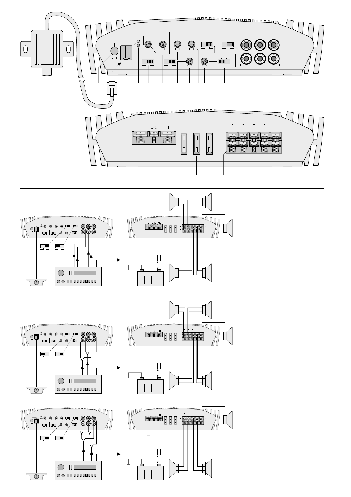
5-Kanalbetrieb
5-channel operation
Mode 5 canaux
Funzionamento a 5 canali
CH1+2
R
L
INPUT
CH3+4
SUB
POWER
PROTECTION
FREQ LP
40 220
LEVEL
8v 100mv
LEVEL LEVEL
8v 100mv 8v 100mv
CH1+2 CH3+4SUB
40 220
FREQ HP
FLAT LP FLAT HP
40 220
40~150Hz to 150Hz
SUB
LEVEL CONTROL
OFFON
FREQ HP
HP B.P FLAT
2CH 4CH
INPUT
SELECT
3.4CH SUB
SUB
SELECT
FUSE
GND
POWER
RMT
BATT
+B
FUSE FUSE
SPEAKER
CH3(L) CH4(R) SUBCH2(R)CH1(L)
BRIDGED BRIDGED
Radio
Speaker L
min. 4Ω
Speaker R
min. 4Ω
On = 12V
R
L
Subwoofer
min. 2Ω
Battery
Fuse
100A
Chassis
Chassis
max.
20cm
2CH 4CH 3.4CH SUB
➄
Brückenbetrieb
Bridge operation
Mode bridgé
Funzionamento a ponte
CH1+2
R
L
INPUT
CH3+4
SUB
POWER
PROTECTION
FREQ LP
40 220
LEVEL
8v 100mv
LEVEL LEVEL
8v 100mv 8v 100mv
CH1+2 CH3+4SUB
40 220
FREQ HP
FLAT LP FLAT HP
40 220
40~150Hz to 150Hz
SUB
LEVEL CONTROL
OFFON
FREQ HP
HP B.P FLAT
2CH 4CH
INPUT
SELECT
3.4CH SUB
SUB
SELECT
FUSE
GND
POWER
RMT
BATT
+B
FUSE FUSE
SPEAKER
CH3(L) CH4(R) SUBCH2(R)CH1(L)
BRIDGED BRIDGED
Radio
Speaker L
min. 2Ω
Speaker R
min. 2Ω
On = 12V
R
kick bass
Speaker L
min. 2Ω
Speaker R
min. 2Ω
L
Subwoofer
min. 2Ω
mid-high
range
Battery
Fuse
100A
Chassis
Chassis
max.
20cm
2CH 4CH 3.4CH SUB
➃
Bi-Amping:
aktiver Kickbaß und Mittelhochtöner
active kick bass and mid-high range speakers
HP de grave actif (kickbass) et HP demédium aigu
woofer (kickbass) attivo e midrange/ tweeter
Page 4

Bitte klappen Sie die Seite 3 heraus. Sie sehen
dann immer die beschriebenen Bedienelemente
und Anschlüsse.
Inhalt
1 Übersicht der Bedienelemente und
Anschlüsse . . . . . . . . . . . . . . . . . . . . . . . . . 4
1.1 Frontseite . . . . . . . . . . . . . . . . . . . . . . . . . . . 4
1.2 Rückseite . . . . . . . . . . . . . . . . . . . . . . . . . . . 4
2 Sicherheitshinweise . . . . . . . . . . . . . . . . . . 5
3 Vorsicht bei hohen Lautstärken . . . . . . . . 5
4 Einsatzmöglichkeiten . . . . . . . . . . . . . . . . . 5
5 Montage . . . . . . . . . . . . . . . . . . . . . . . . . . . . 5
6 Endstufe anschließen . . . . . . . . . . . . . . . . 5
6.1 Stromversorgung . . . . . . . . . . . . . . . . . . . . . 5
6.1.1 Anschluß BATT . . . . . . . . . . . . . . . . . . . . . 5
6.1.2 Anschluß GND . . . . . . . . . . . . . . . . . . . . . . 6
6.1.3 Anschluß RMT . . . . . . . . . . . . . . . . . . . . . . 6
6.2 Eingänge . . . . . . . . . . . . . . . . . . . . . . . . . . . 6
6.2.1 5-Kanalbetrieb . . . . . . . . . . . . . . . . . . . . . . 6
6.2.2 Brückenbetrieb . . . . . . . . . . . . . . . . . . . . . 6
6.3 Lautsprecher . . . . . . . . . . . . . . . . . . . . . . . . . 6
6.3.1 Subwoofer . . . . . . . . . . . . . . . . . . . . . . . . . 6
6.3.2 Breitbandlautsprecher . . . . . . . . . . . . . . . . 6
6.3.3 Kick-Baßlautsprecher und Mittelhochtöner 7
6.3.4 Brückenbetrieb . . . . . . . . . . . . . . . . . . . . . 7
6.4 Pegelregler für den Subwoofer . . . . . . . . . . . 7
7 Inbetriebnahme . . . . . . . . . . . . . . . . . . . . . . 7
7.1 Filter einschalten und
Trennfrequenzen einstellen . . . . . . . . . . . . . 7
7.2 Pegel anpassen . . . . . . . . . . . . . . . . . . . . . . 7
8 Fehlerbeseitigung . . . . . . . . . . . . . . . . . . . . 8
8.1 Keine LED leuchtet . . . . . . . . . . . . . . . . . . . . 8
8.2 Grüne LED POWER leuchtet . . . . . . . . . . . . 8
8.3 Rote LED PROTECTION leuchtet . . . . . . . . 8
9 Technische Daten . . . . . . . . . . . . . . . . . . . . 8
1 Übersicht der Bedienelemente und
Anschlüsse
1.1 Frontseite
1 Pegelregler für den Subwoofer zur Bedienung
vom Fahrersitz aus
2 Ein-/Ausschalter für den externen Pegelregler (1)
des Subwoofers
3 Steckkontakt für den externen Pegelregler (1)
des Subwoofers
4 Betriebsanzeige POWER
5 Anzeige PROTECTION leuchtet bei aktivierter
Schutzschaltung:
1. wenn einer der Lautsprecherausgänge (22)
kurzgeschlossen ist
2. wenn der Verstärker überhitzt ist
6 Schalter für den Tiefpaß im Subwoofer-Kanal
FLAT Tiefpaß ausgeschaltet
LP Tiefpaß eingeschaltet
7 Trimmregler FREQ LP für die Trennfrequenz des
Tiefpasses im Subwoofer-Kanal
8 Trimmregler LEVEL zur Eingangspegelanpas-
sung des Subwoofer-Kanals
9 Schalter für die Hochpässe der Kanäle 1 und 2
FLAT Hochpässe ausgeschaltet
HP Hochpässe eingeschaltet
10 Trimmregler LEVEL zur Eingangspegelanpas-
sung der Kanäle 1 und 2
11 Trimmregler FREQ HPfür die Trennfrequenz der
Hochpässe in den Kanälen 1 und 2
12 Trimmregler LEVEL zur Eingangspegelanpas-
sung der Kanäle 3 und 4
13 Trimmregler FREQ HP für die Filter in den
Kanälen 3 und 4;
Funktion abhängig vom Schiebeschalter (15):
Position HP
Trennfrequenz der Hochpässe einstellbar
Position B.P
untere Grenzfrequenz der Bandpässe einstellbar
14 Eingangswahlschalter INPUT SELECT für die
Line-Eingänge (17) der Kanäle 1– 4
2CH Die Signale an den Buchsen CH1+2 wer-
den sowohl auf die Kanäle 1 und 2 als
auch auf die Kanäle 3 und 4 gegeben;
die Buchsen CH3+4 sind abgeschaltet
4CH Die Kanäle 1 und 2 sowie 3 und 4 wer-
den getrennt über die Buchsen CH1+2
und CH3+4 angesteuert
15 Schalter für die Filter in den Kanälen 3 und 4
FLAT Filter ausgeschaltet
B.P Bandpässe eingeschaltet
HP Hochpässe eingeschaltet
16 Eingangswahlschalter SUB SELECT für die
Line-Eingänge (17) des Subwoofer-Kanals
3.4CH Der Subwoofer-Kanal wird über die
Buchsen CH3+4 angesteuert;
die Buchsen SUB sind abgeschaltet
SUB Der Subwoofer-Kanal wird über die
Buchsen SUB angesteuert
17 Line-Eingänge
1.2 Rückseite
18 Masseanschluß GND
19 Steuereingang RMT zum Einschalten der Car-
HiFi-Endstufe über eine 12-V-Spannung
20 Anschluß BATT für die Betriebsspannung +12V
21 Sicherungen (3 x 30A);
eine durchgebrannte Sicherung nur durch eine
gleichen Typs ersetzen
22 Lautsprecheranschlüsse
Please unfold page 3. Then you can always see
the operating elements and connections described.
Contents
1 Operating Elements and Connections . . . 4
1.1 Front side . . . . . . . . . . . . . . . . . . . . . . . . . . . 4
1.2 Rear side . . . . . . . . . . . . . . . . . . . . . . . . . . . 4
2 Safety Notes . . . . . . . . . . . . . . . . . . . . . . . . 5
3 Caution in Case of High Volumes . . . . . . . 5
4 Applications . . . . . . . . . . . . . . . . . . . . . . . . 5
5 Mounting . . . . . . . . . . . . . . . . . . . . . . . . . . . 5
6 Connection of the Power Amplifier . . . . . . 5
6.1 Power supply . . . . . . . . . . . . . . . . . . . . . . . . 5
6.1.1 Terminal BATT . . . . . . . . . . . . . . . . . . . . . . 5
6.1.2 Terminal GND . . . . . . . . . . . . . . . . . . . . . . 5
6.1.3 Terminal RMT . . . . . . . . . . . . . . . . . . . . . . 6
6.2 Inputs . . . . . . . . . . . . . . . . . . . . . . . . . . . . . . 6
6.2.1 5-channel operation . . . . . . . . . . . . . . . . . . 6
6.2.2 Bridge operation . . . . . . . . . . . . . . . . . . . . 6
6.3 Speakers . . . . . . . . . . . . . . . . . . . . . . . . . . . 6
6.3.1 Subwoofer . . . . . . . . . . . . . . . . . . . . . . . . . 6
6.3.2 Full range speakers . . . . . . . . . . . . . . . . . . 6
6.3.3 Kick bass speakers and
mid-high range speakers . . . . . . . . . . . . . . 6
6.3.4 Bridge operation . . . . . . . . . . . . . . . . . . . . 7
6.4 Level control for the subwoofer . . . . . . . . . . 7
7 Setting into Operation . . . . . . . . . . . . . . . . 7
7.1 Switching on the filters and adjusting the
crossover frequencies . . . . . . . . . . . . . . . . . 7
7.2 Level matching . . . . . . . . . . . . . . . . . . . . . . 7
8 Trouble Shooting . . . . . . . . . . . . . . . . . . . . 8
8.1 No LED lights up . . . . . . . . . . . . . . . . . . . . . . 8
8.2 Green LED POWER lights up . . . . . . . . . . . . 8
8.3 Red LED PROTECTION lights up . . . . . . . . 8
9 Specifications . . . . . . . . . . . . . . . . . . . . . . . 8
1 Operating Elements and Connections
1.1 Front side
1 Level control for the subwoofer for the operation
from the driver’s seat
2 On/ off switch for the external level control (1) of
the subwoofer
3 Plug-in contact for the external level control (1) of
the subwoofer
4 Operating LED POWER
5 LED PROTECTION lights up in case of activated
protection circuit:
1. if one of the speaker outputs (22) is short-circuited
2. if the amplifier is overheated
6 Switch for the low pass in the subwoofer channel
FLAT low pass switched off
LP low pass switched on
7 Trimming control FREQ LP for the crossover fre-
quency of the low pass in the subwoofer channel
8 Trimming control LEVEL for input level matching
of the subwoofer channel
9 Switch for the high passes in channels 1 and 2
FLAT high passes switched off
HP high passes switched on
10 Trimming control LEVEL for the input level
matching of channels 1 and 2
11 Trimming control FREQ HP for the crossover fre-
quency of the high passes in channels 1 and 2
12 Trimming control LEVEL for the input level
matching of channels 3 and 4
13 Trimming control FREQ HP for the filters in chan-
nels 3 and 4;
function depending on the sliding switch (15):
position HP
crossover frequency of the high passes can
be adjusted
position B.P
lower limit frequency of the band passes can
be adjusted
14 Input selector switch INPUT SELECTfor the line
inputs (17) of channels 1 to 4
2CH the signals at jacks CH1+2 are fed to
channels 1 and 2 as well as to channels
3 and 4; jacks CH3+4 are switched off
4CH Channels 1 and 2 as well as 3 and 4 are
separately controlled via jacks CH1+2
and CH3+4
15 Switch for the filters in channels 3 and 4
FLAT filters switched off
B.P band passes switched on
HP high passes switched on
16 Input selector switch SUB SELECT for the line
inputs (17) of the subwoofer channel
3.4CH The subwoofer channel is controlled via
jacks CH3+4; jacks SUB are switched off
SUB The subwoofer channel is controlled via
jacks SUB
17 Line inputs
1.2 Rear side
18 Ground connection GND
19 Control input RMT to switch on the car HiFi
power amplifier via a 12V voltage
20 Terminal BATT for the operating voltage +12 V
21 Fuses (3 x 30A);
only replace a blown fuse by one of the same
type
22 Speaker connections
4
GB
D
A
CH
Page 5
2 Sicherheitshinweise
Das Gerät entspricht der Richtlinie 89/336/EWG für
elektromagnetische Verträglichkeit.
●
Beim Anschluß der Car-HiFi-Endstufe an die Autobatterie ist besondere Sorgfalt geboten. Bei Kurzschlüssen können sehr gefährlich hohe Ströme
fließen. Schrauben Sie deshalb unbedingt vor dem
Anschluß die Minusklemme der Autobatterie ab.
●
Die Endstufe muß fest und fachgerecht an einer
mechanisch stabilen Stelle im Auto montiert werden, damit sie sich nicht löst und zu einem gefährlichen Geschoß wird.
●
Während des Betriebs kann das Gerät sehr heiß
werden. Plazieren Sie darum keine hitzeempfindlichen Gegenstände in der Nähe, und berühren
Sie die Endstufe nicht während des Betriebs.
●
Verwenden Sie für die Reinigung nur ein trockenes, weiches Tuch, auf keinen Fall Chemikalien
oder Wasser.
●
Wird das Gerät zweckentfremdet, falsch bedient,
nicht richtig angeschlossen oder nicht fachgerecht
repariert, kann für eventuelle Schäden keine Haftung übernommen werden.
●
Soll das Gerät endgültig aus dem Betrieb genommen werden, übergeben Sie es zur Entsorgung
einem örtlichen Recyclingbetrieb.
3 Vorsicht bei hohen Lautstärken
●
Stellen Sie die Lautstärke nie sehr hoch ein.
Extrem hohe Lautstärken können das Gehör
schädigen.
●
Das menschliche Ohr gewöhnt sich an hohe Lautstärken und empfindet sie nach einiger Zeit als
nicht mehr so hoch. Erhöhen Sie darum eine einmal eingestellte hohe Lautstärke nach der
Gewöhnung nicht weiter.
●
Während des Autofahrens dürfen Signaltöne, z.B.
von einem Rettungswagen, nicht durch eine zu
hohe Lautstärke der Car-HiFi-Anlage übertönt
werden.
●
Bei ausgeschaltetem Motor sollte die Car-HiFiAnlage nicht längere Zeit mit hoher Lautstärke
betrieben werden. Die Autobatterie wird schnell
entladen und liefert dann eventuell nicht mehr genügend Energie zum Starten.
4 Einsatzmöglichkeiten
Die Endstufe WANTED-5/ 380 mit fünf Verstärkerkanälen ist speziell für Car-HiFi-Anlagen konzipiert.
Vier Kanäle können Breitbandlautsprecher antreiben
bzw. durch die zuschaltbaren Hochpässe auch Mittelhochtöner. Alternativ sind in den Kanälen 3 und 4
Bandpässe für Kick-Baßlautsprecher zuschaltbar.
Um eine größere Ausgangsleistung für zwei Kanäle
zu erhalten, lassen sich je zwei Kanäle in Brücke
zusammenschalten. Ein separater Kanal mit zuschaltbarem Tiefpaß dient zum Anschluß eines Subwoofers.
5 Montage
Bei der Auswahl des Montageplatzes unbedingt die
folgenden Punkte beachten:
●
Das 12-V-Stromversorgungskabel von der Batterie zur Car-HiFi-Endstufe sollte so kurz wie möglich sein. Es ist günstiger, längere Lautsprecherkabel zu verwenden und dafür ein kürzeres
Stromversorgungskabel.
●
Die Masseleitung von der Endstufe zum Fahrzeugchassis sollte ebenfalls so kurz wie möglich sein.
●
Um die entstehende Wärme der Car-HiFi-Endstufe ableiten zu können, muß eine ausreichende
Belüftung gewährleistet sein.
●
Wegen der beim Bremsen auftretenden Kräfte
muß die Endstufe an einer mechanisch stabilen
Stelle angeschraubt werden.
●
Die Sicherungen und die Regler müssen zugänglich sein.
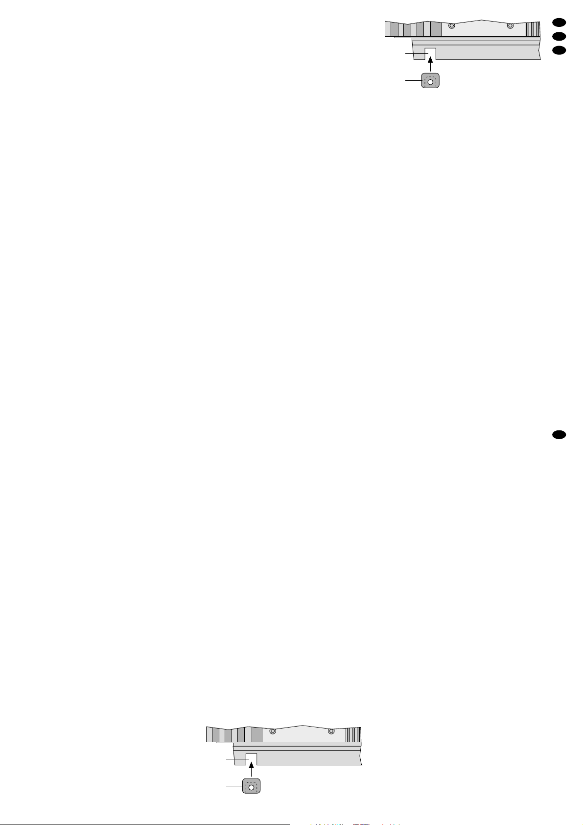
1) In die vier Aussparungen (a) der beiden Befestigungswinkel je eine der beiliegenden Kunststoffbuchsen (b) einsetzen (Abb. 5).
Einsetzen einer Kunststoffbuchse
➄
2) Die Car-HiFi-Endstufe über die Kunststoffbuchsen an geeigneter Stelle mit vier Schrauben fest
montieren.
6 Endstufe anschließen
●
Der Anschluß der Car-HiFi-Endstufe an das Bordnetz darf nur durch qualifiziertes Fachpersonal
erfolgen.
●
Unbedingt vor dem Anschluß die Minusklemme
der Autobatterie abschrauben, um bei einem
eventuellen Kurzschluß während der Installation
Schäden zu vermeiden.
●
Die erforderlichen Kabel so verlegen, daß deren
Isolierung nicht beschädigt werden kann.
Der gesamte Anschluß ist in den Abbildungen 3–5
auf der Seite 3 dargestellt.
6.1 Stromversorgung
6.1.1 Anschluß BATT (20)
Den Anschluß BATT über ein entsprechendes Kabel
mit der Plusklemme der Autobatterie verbinden. Um
den Spannungsverlust durch das Kabel gering zu
halten, sollte mindestens ein Querschnitt von
20mm
2
verwendet werden, z.B. CPC-200/RT*. Um
die neu verlegte 12-V-Leitung gegen einen Kurzschluß abzusichern, muß eine 100-A-Vorsicherung
(z.B. CPF-100GF*) in unmittelbarer Nähe der Batterie zwischengesetzt werden (Abb.3 – 5).
Zur Stabilisierung der Betriebsspannung für die
Endstufe und der damit verbundenen Leistungsstei-
*von CARPOWER
a
b
2 Safety Notes
The unit corresponds to the directive 89/ 336 / EEC
for electromagnetic compatibility.
●
When connecting the car HiFi power amplifier to the
car battery, be especially careful. In case of short
circuits there may be dangerously high currents.
Therefore, prior to the connection it is indispensable
to screw off the negative terminal of the car battery .
●
The power amplifier must be mounted to a
mechanically stable place in the car. It must be
skilfully fixed so that it does not get loose and turn
into a dangerous projectile.
●
During operation the unit may become very hot.
Therefore, do not place any objects sensitive to
heat near it and do not touch the power amplifier
while in operation.
●
For cleaning only use a dry, soft cloth, by no
means chemicals or water.
●
If the unit is used for purposes other than originally
intended, if it is not correctly operated or connected or not repaired in a qualified way, no liability can be taken over for any possible damage.
●
If the unit is to be put out of operation definitively,
it must be disposed of in a local recycling plant.
3 Caution in Case of High Volumes
●
Never adjust the volume very high. Extremely high
volumes may damage your hearing.
●
The human ear gets accustomed to high volumes
which do not seem to be so high any more after
some time. Therefore, do not increase a high
volume which has once been adjusted after getting used to it.
●
While driving in the car, signal sounds, e.g. by an
ambulance, must not be drowned by the volume
of the car HiFi system which has been adjusted
too high.
●
With the motor switched off, the car HiFi system
should not be in operation for a longer period of
time. The car battery will quickly be discharged,
and then it may not be capable any more of supplying sufficient energy for starting the car.
4 Applications
The power amplifier WANTED-5/ 380 with five amplifier channels is especially designed for car HiFi
systems. Four channels can drive full range
speakers or, due to switchable high passes, midhigh range speakers as well. As an alternative, it is
possible to switch on band passes for kick bass
speakers in channels 3 and 4. To obtain a greater
output power for two channels, bridge connection of
two channels each is possible. A separate channel
with switchable low pass serves for the connection
of a subwoofer.
5 Mounting
When choosing the place of mounting, always observe the following items in any case:
●
The 12 V power supply cable from the battery to
the car HiFi power amplifier should be as short as
possible. It is more advantageous to use longer
speaker cables and a shorter power supply cable
instead.
●
The ground cable from the power amplifier to the
chassis of the car should also be as short as
possible.
●
For carrying off the heat being generated in the
car HiFi power amplifier, a sufficient ventilation
has to be ensured.
●
As forces occur during braking, the power amplifier
must be screwed to a mechanically stable place.
●
The fuses and the controls must be accessible.
1) Insert one of the supplied plastic jacks each (b)
into the four cutouts (a) of the two fixing brackets.
Insertion of a plastic jack
➄
2) Firmly mount the car HiFi power amplifier with
four screws via the plastic jacks at a suitable
place.
6 Connection of the Power Amplifier
●
The connection of the car HiFi power amplifier to
the electric system of the car must only be carried
out by authorized personnel.
●
To prevent damage in case of a possible short circuit during installation, prior to the connection it is
indispensable to screw off the negative terminal of
the car battery.
●
Lay the necessary cables so that their insulation
cannot be damaged.
The complete connection is shown in figs. 3– 5 on
page 3.
6.1 Power supply
6.1.1 Terminal BATT (20)
Connect the terminal BATT via a corresponding
cable to the positive terminal of the car battery. To
keep the voltage loss by the cable as low as possible, a cross section of 20mm
2
should be used as a
minimum, e.g. CPC-200/RT*. To protect the newly
laid 12V cable against short circuit, a 100 Aadditional fuse (e. g. CPF-100GF*) must be inserted very
close to the battery (figs. 3– 5).
To stabilize the operating voltage for the power
amplifier and the resulting power increase as well as
sound improvement, a power capacitor is recommended, e.g. CPS-1000*.
6.1.2 Terminal GND (18)
Connect the ground terminal GND via a cable with a
cross section of min. 20 mm
2
(e. g. CPC-200 / SW*)
to the ground of the car or directly to the negative
terminal of the car battery. To avoid ground loops,
the ground of the car radio must be placed at the
spot where also the power amplifier is grounded.
* by CARPOWER
a
b
5
GB
D
A
CH
Page 6

gerung sowie Klangverbesserung wird ein PowerKondensator empfohlen, z.B. CPS-1000*.
6.1.2 Anschluß GND (18)
Den Masseanschluß GND über ein Kabel mit einem
Querschnitt von mindestens 20mm
2
(z.B. CPC200/SW*) mit der Masse des Autos oder direkt mit
der Minusklemme der Autobatterie verbinden. Zur
Vermeidung von Masseschleifen muß die Masse
des Autoradios an die Stelle gelegt werden, an der
auch die Endstufe an Masse liegt.
6.1.3 Anschluß RMT (19)
Die Car-HiFi-Endstufe wird durch eine Steuerspannung von +12V am Anschluß RMT ein- und ausgeschaltet. Den Anschluß RMTmit dem 12-V-Ausgang
vom Autoradio verbinden (Anschluß für eine Motorantenne, eventuell mit der Motorantenne parallelschalten).
Wenn kein 12-V-Ausgang am Autoradio vorhanden ist, muß der Anschluß RMT eine 12-V-Spannung über das Zündschloß oder über einen separaten Schalter erhalten.
6.2 Eingänge
Die Endstufe wird über Cinch-Kabel mit den LineAusgängen am Autoradio verbunden. Sind am Autoradio jedoch keine Line-Ausgänge vorhanden, können die Lautsprecherausgänge des Autoradios über
einen entsprechenden Übertrager (z. B. FGA-20*)
mit den Line-Eingängen der Endstufe verbunden
werden. Der genaue Anschluß richtet sich nach der
gewünschten Betriebsart der Endstufe:
6.2.1 5-Kanalbetrieb (Abb. 3)
Die Ausgänge des Autoradios mit den Eingängen
INPUT (17) der folgenden Kanäle verbinden:
Front Links auf Kanal 1 (linke weiße Buchse)
Front Rechts auf Kanal 2 (linke rote Buchse)
Rear Links auf Kanal 3 (mittlere weiße Buchse)
Rear Rechts auf Kanal 4 (mittlere rote Buchse)
Den Schalter INPUT SELECT (14) in die Position
4CH stellen.
*von CARPOWER
Sind am Autoradio auch Ausgänge für einen Subwoofer-Kanal vorhanden, diese mit den Buchsen
SUB verbinden und den Schalter SUB SELECT (16)
in die Position SUB stellen.
Sind keine Ausgänge für einen Subwoofer-Kanal
vorhanden, den Schalter SUB SELECT (16) in die
Position 3.4CH stellen. Dadurch erhält der Subwoofer-Kanal das Signal der Buchsen CH3+4.
Sind am Autoradio weder Ausgänge für die hinteren
Kanäle (Rear) noch Ausgänge für den SubwooferKanal vorhanden, den Ausgang des linken Kanals
über ein Y -Kabel (z.B. CBA-25/SW*) mit den beiden
weißen Buchsen für die Kanäle 1 und SUB verbinden und den Ausgang des rechten Kanals über ein
weiteres Y-Kabel mit den roten Buchsen für die
Kanälen 2 und SUB (siehe auch Abb. 4). Den Schalter INPUT SELECT (14) in die Position 2CH stellen
und den Schalter SUB SELECT (16) in die Position
SUB.
6.2.2 Brückenbetrieb (Abb. 5)
1) Den linken Ausgang des Autoradios über zwei Y-
Kabel (z.B. CBA-25/SW*) mit den folgenden Ein-
gängen INPUT (17) der Endstufe verbinden:
Kanal 1 und 2 sowie untere weiße Buchse SUB.
2) Den rechten Ausgang des Autoradios über zwei
Y-Kabel mit den folgenden Eingängen der End-
stufe verbinden:
Kanal 3 und 4 sowie obere rote Buchse SUB.
3) Den Schalter INPUT SELECT (14) in die Position
4CH stellen und den Schalter SUB SELECT (16)
in die Position SUB.
6.3 Lautsprecher
Es können vier Breitbandlautsprecher und ein Subwoofer betrieben werden oder anstelle der Breitbandlautsprecher in den Kanälen 1 und 2 bei eingeschalteten Hochpaßfiltern je ein Mittelhochtöner
sowie in den Kanälen 3 und 4 bei eingeschalteten
Bandpässen je ein Kick-Baßlautsprecher. Im Brükkenbetrieb stehen zwei Kanäle mit erhöhter Ausgangsleistung zur Verfügung.
6.3.1 Subwoofer
Die größte Ausgangsleistung wird beim Anschluß
eines 2-Ω-Subwoofers oder einer Lautsprechergruppe mit einer Gesamtimpedanz von 2 Ω (z.B.
zwei 4-Ω-Lautsprecher oder vier 8-Ω-Lautsprecher
parallelgeschaltet) erreicht. Es können jedoch auch
einzelne 4-Ω- oder 8-Ω-Subwoofer angeschlossen
werden, wobei sich die Ausgangsleistung verringert.
Den Subwoofer an die Klemmen SPEAKER SUB
(22) anschließen – siehe auch Abb. 3–5:
SUB+ = Pluspol Subwoofer
SUB
-
= Minuspol Subwoofer
6.3.2 Breitbandlautsprecher
Die größte Ausgangsleistung wird beim Anschluß
von 2-Ω-Lautsprechern oder einer Lautsprechergruppe mit einer Gesamtimpedanz von 2Ω pro
Kanal erreicht (z.B. zwei 4-Ω-Lautsprecher oder
vier 8-Ω-Lautsprecher parallelgeschaltet). Es können jedoch auch einzelne 4-Ω- oder 8-Ω-Lautsprecher angeschlossen werden, wobei sich die Ausgangsleistung verringert.
Die Lautsprecher an die Klemmen SPEAKER CH1
bis CH4 (22) anschließen – siehe auch Abb. 3:
CH1(L)+ = Pluspol Lautsprecher links vorne
CH1(L)
-
= Minuspol Lautsprecher links vorne
CH2(R)+ = Pluspol Lautsprecher rechts vorne
CH2(R)
-
= Minuspol Lautsprecher rechts vorne
CH3(L)+ = Pluspol Lautsprecher links hinten
CH3(L)
-
= Minuspol Lautsprecher links hinten
CH4(R)+ = Pluspol Lautsprecher rechts hinten
CH4(R)
-
= Minuspol Lautsprecher rechts hinten
Wichtig! Alle Lautsprecher müssen 2polig ange-
schlossen werden, d. h. ohne gemeinsamen Masseanschluß.
Bei der Auswahl geeigneter Lautsprecher unbedingt deren mechanische und
elektrische Belastbarkeit im Zusammenhang mit der genutzten Endstufenleistung berücksichtigen (siehe auch
technische Daten der Endstufe Seite 8).
6.1.3 Terminal RMT (19)
The car HiFi power amplifier is switched on and off
by a control voltage of +12 V at the terminal RMT.
Connect the terminal RMT to the 12V output of the
car radio (connection for a motor antenna, if necessary, connect in parallel with the motor antenna).
If no 12V output is provided on the car radio, the
terminal RMTmust get a 12V voltage via the ignition
lock or a separate switch.
6.2 Inputs
The power amplifier is connected via cables with
phono connectors to the line outputs at the car radio.
If, however, no line outputs are provided at the car
radio, the speaker outputs of the car radio can be
connected via a corresponding transformer (e.g.
FGA-20* to the line inputs of the power amplifier.
The exact connection depends on the desired
operating mode of the power amplifier:
6.2.1 5-channel operation (fig. 3)
Connect the outputs of the car radio to the INPUTs
(17) of the following channels:
front left to channel 1 (left white jack)
front right to channel 2 (left red jack)
rear left to channel 3 (middle white jack)
rear right to channel 4 (middle red jack)
Set switch INPUT SELECT (14) to position 4CH.
If the car radio is also provided with outputs for a sub-
woofer channel, connect them to jacks SUB and set
switch SUB SELECT (16) to position SUB.
If no outputs are provided for a subwoofer channel, set switch SUB SELECT (16) to position 3.4CH.
Thus, the subwoofer channel receives the signal of
jacks CH3+4.
* by CARPOWER
If the car radio is neither equipped with outputs for
the rear channels nor with outputs for the subwoofer
channel, connect the output of the left channel via a
Y cable (e.g. CBA-25/ SW*) to the two white jacks
for channels 1 and SUB and the output of the right
channel via another Y cable to the red jacks for
channels 2 and SUB (also see fig. 4). Set switch
INPUT SELECT (14) to position 2CH and switch
SUB SELECT (16) to position SUB.
6.2.2 Bridge operation (fig. 5)
1) Connect the left output of the car radio via two Y
cables (e. g. CBA-25/ SW*) to the following INPUTs (17) of the power amplifier:
channels 1 and 2 as well as lower white jack
SUB.
2) Connect the right output of the car radio via two Y
cables to the following inputs of the power amplifier:
channels 3 and 4 as well as upper red jack SUB.
3) Set switch INPUT SELECT (14) to position 4CH
and switch SUB SELECT (16) to position SUB.
6.3 Speakers
It is possible to operate four full range speakers and
a subwoofer or instead of the full range speakers in
channels 1 and 2 with the high pass filters switched
on one mid-high range speaker each and in channels 3 and 4 with band passes switched on one kick
bass speaker each. In bridge operation two channels are available with increased output power.
6.3.1 Subwoofer
The greatest output power is reached if a 2Ω subwoofer or a speaker group with a total impedance of
2Ω (e. g. two 4Ω speakers or four 8 Ω speakers
connected in parallel). However, it is also possible to
connect individual 4 Ω or 8 Ω subwoofers in which
case the output power is reduced.
Connect the subwoofer to the terminals SPEAKER
SUB (22) – also see figs. 3– 5:
SUB+ = positive pole subwoofer
SUB
-
= negative pole subwoofer
6.3.2 Full range speakers
The greatest output power is reached when
connecting 2Ω speakers or a speaker group with a
total impedance of 2 Ω per channel (e. g. two 4 Ω
speakers or four 8 Ω speakers connected in parallel). However, it is also possible to connect individual
4Ω or 8Ω speakers in which case the output power
is reduced.
Connect the speakers to the terminals SPEAKER
CH1 to CH 4 (22) – also see fig. 3:
CH1(L)+ = positive pole speaker left front
CH1(L)
-
= negative pole speaker left front
CH2(R)+ = positive pole speaker right front
CH2(R)-= negative pole speaker right front
CH3(L)+ = positive pole speaker left rear
CH3(L)
-
= negative pole speaker left rear
CH4(R)+ = positive pole speaker right rear
CH4(R)
-
= negative pole speaker right rear
6.3.3 Kick bass speakers and mid-high range
speakers
The greatest output power is reached when
connecting 2Ω speakers or a speaker group with a
total impedance of 2 Ω per channel (e. g. two 4 Ω
speakers or four 8 Ω speakers connected in parallel). However, it is also possible to connect individual
4Ω or 8Ω speakers in which case the output power
is reduced.
Connect the speakers to the terminals SPEAKER
CH1 to CH 4 (22) – also see fig. 4:
Important! All speakers must be connected with
2 poles, i.e. without common ground
connection.
When choosing suitable speakers, pay
in any case attention to their mechanical and electrical capability in connection with the applied power of the
power amplifier (also see specifications of the power amplifier on page 8).
6
GB
D
A
CH
Page 7

6.3.3 Kick-Baßlautsprecher und Mittelhochtöner
Die größte Ausgangsleistung wird beim Anschluß
von 2-Ω-Lautsprechern oder einer Lautsprechergruppe mit einer Gesamtimpedanz von 2Ω pro
Kanal erreicht (z.B. zwei 4-Ω-Lautsprecher oder
vier 8-Ω-Lautsprecher parallelgeschaltet). Es können jedoch auch einzelne 4-Ω- oder 8-Ω-Lautsprecher angeschlossen werden, wobei sich die Ausgangsleistung verringert.
Die Lautsprecher an die Klemmen SPEAKER CH1
bis CH4 (22) anschließen – siehe auch Abb. 4:
CH1(L)+ = Pluspol Mittelhochtöner links
CH1(L)
-
= Minuspol Mittelhochtöner links
CH2(R)+ = Pluspol Mittelhochtöner rechts
CH2(R)
-
= Minuspol Mittelhochtöner rechts
CH3(L)+ = Pluspol Kick-Baßlautsprecher links
CH3(L)
-
= Minuspol Kick-Baßlautsprecher links
CH4(R)+ = Pluspol Kick-Baßlautsprecher rechts
CH4(R)
-
= Minuspol Kick-Baßlautsprecher rechts
6.3.4 Brückenbetrieb
Im Brückenbetrieb darf die Impedanz der angeschlossenen Lautsprecher bzw. die Gesamtimpedanz einer Lautsprechergruppe 4Ω nicht unterschreiten! Die Lautsprecher an die Klemmen
SPEAKER CH1 bis CH4 (22) anschließen, wobei
die Beschriftung „BRIDGED“ zu beachten ist – siehe
auch Abb. 5:
CH1(L)+ = Pluspol Lautsprecher links
CH1(L)
-
= bleibt frei
CH2(R)+ = bleibt frei
CH2(R)
-
= Minuspol Lautsprecher links
CH3(L)+ = Pluspol Lautsprecher rechts
CH3(L)
-
= bleibt frei
CH4(R)+ = bleibt frei
CH4(R)
-
= Minuspol Lautsprecher rechts
6.4 Pegelregler für den Subwoofer
Den Pegelregler (1) für den Subwoofer in Fahrerreichweite montieren. Das Anschlußkabel in die
Buchse SUB LEVEL CONTROL (3) stecken.
7 Inbetriebnahme
7.1 Filter einschalten und Trennfrequenzen
einstellen
Je nach verwendetem Lautsprechertyp mit den
Schaltern (6, 9, 15) das benötigte Filter einschalten.
Für Breitbandlautsprecher die Schalter (9 und 15)
in die Position FLATschieben. Die Kanäle 1– 4 verstärken den gesamten Frequenzbereich. Die Regler
FREQ HP (11 und 13) sind ohne Funktion.
Für Mittelhochtöner die Schalter (9 und 15) in die
Position HP schieben. In den Kanälen 1 – 4 sind die
Hochpässe eingeschaltet, und die tiefen Frequenzen werden damit unterdrückt. Die Trennfrequenzen
mit den Reglern FREQ HP (11 und 13) zunächst
grob einstellen.*
Für Kick-Baßlautsprecher den Schalter (15) in die
Position B.P schieben. In den Kanälen 3 und 4 sind
die Bandpässe eingeschaltet. Die hohen und die
ganz tiefen Frequenzen werden damit unterdrückt.
Die untere Grenzfrequenz mit dem Regler FREQ
HP (13) zunächst grob einstellen.* Die obere Grenzfrequenz liegt fest bei 150Hz.
Für den Subwoofer den Schalter (6) in die Position
LP schieben. Der Tiefpaß ist eingeschaltet, und die
mittleren sowie hohen Frequenzen werden im Subwoofer-Kanal unterdrückt. Die Trennfrequenz mit
dem Regler FREQ LP (7) zunächst grob einstellen.*
* Zur Orientierung den Frequenzbereich der eingesetzten
Lautsprecher beachten. Die Feineinstellung erfolgt nach
der Pegeleinstellung mit entsprechenden Meßgeräten.
7.2 Pegel anpassen
1) Die drei Regler LEVEL(8, 10, 12) ganz nach links
in die Position „8v“ drehen. Den externen Pegelregler (1) für den Subwoofer in die Mittelstellung
drehen, und die T aste SUB LEVELCONTROL(2)
drücken.
2) Die Car-HiFi-Anlage komplett einschalten. Die
grüne LED POWER (4) und der Schriftzug CARPOWER im Fenster auf der Geräteoberseite
leuchten. Der Ton ist jedoch für ca. 3 Sekunden
stummgeschaltet (Einschaltverzögerung).
3) Die Signalquelle, z. B. das Autoradio, auf maximale, nicht verzerrende Lautstärke einstellen
(meistens ca.
3
/4 vom Maximum).
4) Die beiden Regler LEVEL (10 und 12) für die
Kanäle 1– 4 so weit aufdrehen, daß gerade keine
Verzerrungen auftreten.
Beim 5-Kanalbetrieb läßt sich mit diesen Reglern auch die Balance zwischen den vorderen
und hinteren Lautsprechern einstellen, falls am
Autoradio dafür kein Regler vorhanden ist.
Beim Bi-Amping-Betrieb mit den Reglern eine
natürliche oder bewußt verstärkte Kick-Baßwiedergabe einstellen: Sind die Bässe zu leise, die
Kanäle für die Mittelhochtöner im Pegel reduzieren [Regler CH1+2 LEVEL (10)]. Bei einem zu
kräftigen Baß die Lautstärke der Kick-Baßkanäle
verringern [Regler CH3+4 LEVEL (12)].
5) Den Regler SUB LEVEL (8) für den Subwoofer
so weit aufdrehen, daß eine natürliche Baßwiedergabe erreicht wird. Der Baß darf aber nicht
verzerren. In diesem Fall den Regler SUB LEVEL
entsprechend zurückdrehen. Sollte die Baßwiedergabe dann zu schwach sein, die Regler
LEVEL (10 und 12) in den Kanälen 1 –4 entsprechend zurückdrehen.
Tip Um Störeinstrahlungen durch die Autoelektrik
so gering wie möglich zu halten, sollte der
Ausgangspegel der Signalquelle min. 1,5 V
betragen.
!
Vor dem ersten Einschalten die entsprechenden Filter einschalten und die Trennfrequenzen grob einstellen (Kap. 7.1), damit die Lautsprecher nicht durch einen eventuellen zu
großen Frequenzbereich überlastet werden.
Auch sollte die komplette Verdrahtung der
Car-HiFi-Endstufe noch einmal auf Richtigkeit
überprüft werden. Erst danach die Minusklemme der Autobatterie wieder anschließen.
CH1(L)+ = pos. pole mid-high range speaker left
CH1(L)
-
= neg. pole mid-high range speaker left
CH2(R)+ = pos. pole mid-high range speaker right
CH2(R)-= neg. pole mid-high range speaker right
CH3(L)+ = positive pole kick bass speaker left
CH3(L)
-
= negative pole kick bass speaker left
CH4(R)+ = positive pole kick bass speaker right
CH4(R)
-
= negative pole kick bass speaker right
6.3.4 Bridge operation
In bridge operation the impedance of the connected
speakers or the total impedance of a speaker group
must not be lower than 4Ω! Connect the speakers to
the terminals SPEAKER CH1 to CH 4 (22) and pay
attention to the lettering “BRIDGED” – also see fig. 5:
CH1(L)+ = positive pole speaker left
CH1(L)
-
= remains unconnected
CH2(R)+ = remains unconnected
CH2(R)
-
= negative pole speaker left
CH3(L)+ = positive pole speaker right
CH3(L)
-
= remains unconnected
CH4(R)+ = remains unconnected
CH4(R)-= negative pole speaker right
6.4 Level control for the subwoofer
Mount the level control (1) for the subwoofer in
driver’s reach. Plug the connection cable into the
jack SUB LEVEL CONTROL (3).
7 Setting into Operation
7.1 Switching on the filters and adjusting the
crossover frequencies
According to speaker type used, switch on the
necessary filter with the switches (6, 9, 15).
For full range speakers slide the switches (9 and
15) to position FLAT. The channels 1 to 4 amplify the
entire frequency range. The controls FREQ HP (11
and 13) have no function.
For mid-high range speakers slide the switches (9
and 15) to position HP . In the channels 1 to 4 the high
passes are switched on, and the low frequencies are
thus suppressed. First coarsely adjust the crossover
frequencies with the controls FREQ HP (11 and 13).*
For kick bass speakers set switch (15) to position
B.P. The band passes are switched on in channels 3
and 4. Thus, the high and the very low frequencies
are suppressed. First coarsely adjust the lower limit
frequency with control FREQ HP (13).* The upper
limit frequency is fixed at 150 Hz.
For the subwoofer slide the switch (6) to position
LP. The low pass is switched on, and the medium as
well as high frequencies in the subwoofer channel
are suppressed. First coarsely adjust the crossover
frequency with the control FREQ LP (7).*
*For a guidance observe the frequency range of the
speakers used. The fine adjustment is made with the corresponding meters after the level adjustment.
7.2 Level matching
1) Turn the three controls LEVEL (8, 10, 12) to the
left end position “8v”. Turn the external level control (1) for the subwoofer to the mid-position, and
press the button SUB LEVEL CONTROL (2).
2) Switch on the car HiFi system completely. The
green LED POWER (4) and lettering CARPOWER in the window on the upper side of the
unit light up. However, the sound is muted for
approx. 3 seconds (switch-on delay).
3) Adjust the signal source, e.g. the car radio, to the
maximal not distorting volume (in most cases
approx.
3
/4 of the maximum).
4) Turn up the two controls LEVEL(10 and 12) for the
channels 1 to 4 so that just no distortions occur.
In case of 5-channel operation it is possible to
adjust also the balance between the front and the
rear speakers with these controls if no control is
provided on the car radio for this purpose.
For bi-amping operation adjust a natural or
deliberately amplified kick bass reproduction with
the controls: if the volume of the bass frequencies is too low, reduce the levels of the channels
for the mid-high range speakers [control CH1+2
LEVEL (10)]. If the volume of the bass frequencies is too high, reduce the volume of the kick
bass channels [control CH3+4 LEVEL (12)].
5) Turn up the control SUB LEVEL (8) for the subwoofer so that a natural bass reproduction is
reached. However, the bass frequencies must
not be distorted. In this case turn back the control
SUB LEVEL correspondingly. If the bass reproduction should be too poor in this case, turn back
the controls LEVEL (10 and 12) in channels 1 to
4 correspondingly.
For an emphasized or moderate bass repro-
duction it is now possible to correct the bass level
Note To keep the interfering radiation by the elec-
tric system of the car as low as possible, the
output level of the signal source should be
1.5V as a minimum.
!
Prior to the first switching-on, switch on the
corresponding filters and coarsely adjust the
crossover frequencies (chapter 7.1) so that
the speakers are not overloaded by a frequency range that might be too large. It is also
recommended to check the complete wiring of
the car HiFi power amplifier once again for
correctness. Not until then connect the negative terminal of the car battery again.
7
GB
D
A
CH
Page 8

Für eine betonte oder dezente Baßwiedergabe
läßt sich jetzt mit dem externen Regler (1) vom
Fahrersitz aus je nach Musikstück und persönlichem Empfinden der Baßpegel korrigieren.
6) Sind in der Car-HiFi-Anlage weitere Endstufen
eingesetzt, zur Anpassung der Lautstärke aller
Kanäle untereinander die jeweils zu lauten
Kanäle im Pegel reduzieren. (Sollte dann die
Gesamtlautstärke den gewünschten Pegel nicht
erreichen, in die zu schwachen Kanäle kräftigere
Endstufen einsetzen.)
8 Fehlerbeseitigung
Ist nach dem Einschalten der Car-HiFi-Anlage kein
Ton zu hören, den Fehler mit Hilfe der beiden LEDs
POWER (4) und PROTECTION (5) näher lokalisieren.
8.1 Keine LED leuchtet
1) Die Sicherungen (21) an der Car-HiFi-Endstufe
(3 x 30A) und die Vorsicherung an der Autobatterie (100A) überprüfen. Defekte Sicherungen auswechseln. Nur Sicherungen mit den angegebenen Werten verwenden. Auf keinen Fall einen
höheren Wert einsetzen. Die Endstufe kann
beschädigt werden, und die Garantie erlischt.
2) Das 12-V-Stromversorgungskabel sowie das
Massekabel auf korrekten Anschluß und Unterbrechung kontrollieren.
3) An der Klemme RMT (19) der Car-HiFi-Endstufe
messen, ob +12 V anliegt. Wenn nicht, die Leitung an der Klemme RMT entfernen und kurzzeitig die Klemmen RMT (19) und BATT (20)
überbrücken. Schaltet die Car-HiFi-Endstufe jetzt
ein, liegt der Fehler in der fehlenden Steuerspannung. Den 12-V-Ausgang des Autoradios (bzw.
den separaten Schalter oder das Zündschloß)
und das entsprechende Anschlußkabel zur Endstufe überprüfen.
8.2 Grüne LED POWER leuchtet
1) Die Verbindungskabel von der Signalquelle zur
Car-HiFi-Endstufe überprüfen. Sind die Stecker
richtig eingesteckt? Sind die Leitungen unterbrochen?
2) Die Signalquelle überprüfen. Ist die Signalquelle
eingeschaltet? Sind die richtigen Ausgänge verwendet worden? Ist die Signalquelle defekt?
3) Die Lautsprecherkabel auf Unterbrechung überprüfen.
4) Die angeschlossenen Lautsprecher überprüfen.
8.3 Rote LED PROTECTION leuchtet
Die Endstufe ist mit einer Schutzschaltung gegen
Kurzschluß an den Lautsprecherausgängen und
gegen Überhitzung gesichert. Spricht die Schutzschaltung an, leuchtet die rote LED PROTECTION
(5). Bei einer Überhitzung schaltet die Endstufe
nach dem Abkühlen automatisch wieder ein. Bei
einem Kurzschluß an den Lautsprecherausgängen
muß nach der Fehlerbeseitigung zum Zurücksetzen
der Schutzschaltung die Endstufe von der Betriebsspannung getrennt werden (z.B. Vorsicherung kurzzeitig herausnehmen).
9 Technische Daten
Ausgangsleistung
Gesamtleistung: . . . . . . . . . 750W
MAX
Kanäle 1– 4
Brückenbetrieb an 4Ω: . . 2 x 140 W
RMS
4-Kanalbetrieb an 2Ω: . . . 4 x 75WRMS
4-Kanalbetrieb an 4Ω: . . . 4 x 50WRMS
Subwoofer-Kanal
an 2-Ω-Lautsprecher: . . . . 1 x 250 WRMS
an 4-Ω-Lautsprecher: . . . . 1 x 180 WRMS
Frequenzbereich: . . . . . . . . . . 10–30 000 Hz,
-
0,5dB
min. Lautsprecherimpedanz
Kanäle 1– 4
4-Kanalbetrieb: . . . . . . . . . 4 x 2 Ω
Brückenbetrieb: . . . . . . . . 2 x 4 Ω
Subwoofer-Kanal: . . . . . . . . 1 x 2Ω
Line-Eingänge: . . . . . . . . . . . . 6 x Cinch
Empfindlichkeit: . . . . . . . . . . 0,11– 8,8 V
Impedanz: . . . . . . . . . . . . . . 20 kΩ
Filter
Tiefpaß: . . . . . . . . . . . . . . . . 40 – 220Hz,
24dB/Okt.
Hochpaß: . . . . . . . . . . . . . . 40– 220 Hz,
18dB/Okt.
Bandpaß
untere Grenzfrequenz: . . . 40– 150 Hz,
18dB/Okt.
obere Grenzfrequenz: . . . 150Hz, 18dB/Okt.
Kanaltrennung: . . . . . . . . . . . . 81dB
Störabstand: . . . . . . . . . . . . . . 101dB
Klirrfaktor: . . . . . . . . . . . . . . . . < 0,1%
Stromversorgung: . . . . . . . . . . 11– 16 V /90A
Einsatztemperatur: . . . . . . . . . 0 – 40 °C
Abmessungen: . . . . . . . . . . . . 245x65 x 545 mm
Gewicht: . . . . . . . . . . . . . . . . . 6kg
Laut Angaben des Herstellers.
Änderungen vorbehalten.
from the driver’s seat with the external control (1)
according to music piece and personal feeling.
6) If further power amplifiers are used in the car HiFi
system, reduce the levels of the channels which
are too high to match the volumes of all channels
with each other. (In case the total volume should
not reach the desired level, insert more powerful
amplifiers into the channels which are too poor.)
8 Trouble Shooting
If there is no sound after switching on the car HiFi
system, locate the fault more precisely by means of
the two LEDs POWER (4) and PROTECTION (5).
8.1 No LED lights up
1) Check the fuses (21) on the car HiFi power amplifier (3 x 30A) and the additional fuse on the car
battery (100 A). Replace defective fuses. Only
use fuses with the values as indicated. Do not
insert a fuse of a higher value under any circumstances. The power amplifier may be damaged,
and the guarantee will expire.
2) Check the 12V power supply cable as well as the
ground cable for interruption and correct connection.
3) Check at the terminal RMT (19) of the car HiFi
power amplifier if +12V is present. If not, remove
the cable at the terminal RMT, and shortly bridge
the terminals RMT (19) and BATT (20). If the car
HiFi power amplifier switches on now, the error is
due to the missing control voltage. Check the
12V output of the car radio (or the separate
switch or the ignition lock) and the corresponding
connection cable to the power amplifier.
8.2 Green LED POWER lights up
1) Check the connection cable from the signal source
to the car HiFi power amplifier. Are the plugs correctly connected? Is the cable interrupted?
2) Check the signal source. Is the signal source
switched on? Have the correct outputs been
used? Is the signal source defective?
3) Check the speaker cables for interruption.
4) Check the connected speakers.
8.3 Red LED PROTECTION lights up
The power amplifier is protected with a protection
circuit against short circuit at the speaker outputs
and against overheating. If the protection circuit responds, the red LED PROTECTION (5) lights up. In
case of overheating the power amplifier switches on
again automatically after cooling-off. In case of a
short circuit at the speaker outputs, after eliminating
the error, the power amplifier must be separated
from the operating voltage to reset the protection circuit (e.g. shortly remove additional fuse).
9 Specifications
Output power
Total power: . . . . . . . . . . . . . 750 W
MAX
Channels 1– 4
bridge operation at 4Ω: . . 2 x 140W
RMS
4-channel oper. at 2Ω: . . . 4 x 75 WRMS
4-channel oper. at 4Ω: . . . 4 x 50 WRMS
Subwoofer channel
at 2Ω speaker: . . . . . . . . . 1 x 250 WRMS
at 4Ω speaker: . . . . . . . . . 1 x 180 WRMS
Frequency range: . . . . . . . . . . 10 – 30 000Hz,
-
0.5dB
Min. speaker impedance
Channels 1– 4
4-channel operation: . . . . 4 x 2 Ω
bridge operation: . . . . . . . 2 x 4Ω
Subwoofer channel: . . . . . . 1 x 2 Ω
Line inputs: . . . . . . . . . . . . . . . 6 x phono
Sensitivity: . . . . . . . . . . . . . . 0.11– 8.8 V
Impedance: . . . . . . . . . . . . . 20 kΩ
Filters
Low pass: . . . . . . . . . . . . . . 40 – 220 Hz,
24dB/oct.
High pass: . . . . . . . . . . . . . . 40– 220 Hz,
18dB/oct.
Band pass
lower limit frequency: . . . . 40 – 150 Hz,
18dB/oct.
upper limit frequency: . . . . 150 Hz, 18 dB/oct.
Channel separation: . . . . . . . . 81 dB
S/N ratio: . . . . . . . . . . . . . . . . 101 dB
THD: . . . . . . . . . . . . . . . . . . . . < 0.1%
Power supply: . . . . . . . . . . . . . 11– 16 V /90A
Ambient temperature: . . . . . . . 0 – 40°C
Dimensions: . . . . . . . . . . . . . . 245 x 65 x 545mm
Weight: . . . . . . . . . . . . . . . . . . 6 kg
According to the manufacturer.
Subject to change.
8
GB
D
A
CH
Page 9

Ouvrez le présent livret page 3 de manière à
visualiser les éléments et branchements.
Table des matières
1 Eléments et branchements . . . . . . . . . . . . 9
1.1 Face avant . . . . . . . . . . . . . . . . . . . . . . . . . . 9
1.2 Face arrière . . . . . . . . . . . . . . . . . . . . . . . . . 9
2 Conseils de sécurité . . . . . . . . . . . . . . . . . 10
3 Attention: Volumes élevés . . . . . . . . . . . . 10
4 Possibilités d’utilisation . . . . . . . . . . . . . 10
5 Montage . . . . . . . . . . . . . . . . . . . . . . . . . . . 10
6 Branchements . . . . . . . . . . . . . . . . . . . . . . 10
6.1 Alimentation . . . . . . . . . . . . . . . . . . . . . . . . 10
6.1.1 Borne BATT . . . . . . . . . . . . . . . . . . . . . . . 10
6.1.2 Borne GND . . . . . . . . . . . . . . . . . . . . . . . 11
6.1.3 Borne RMT . . . . . . . . . . . . . . . . . . . . . . . . 11
6.2 Entrées . . . . . . . . . . . . . . . . . . . . . . . . . . . . 11
6.2.1 Mode 5 canaux . . . . . . . . . . . . . . . . . . . . 11
6.2.2 Mode bridgé . . . . . . . . . . . . . . . . . . . . . . . 11
6.3 Haut-parleurs . . . . . . . . . . . . . . . . . . . . . . . 11
6.3.1 Subwoofer . . . . . . . . . . . . . . . . . . . . . . . . 11
6.3.2 Haut-parleurs large bande . . . . . . . . . . . . 11
6.3.3 Haut-parleurs kickbass et
haut-parleurs médium-aigu . . . . . . . . . . . 12
6.3.4 Mode bridgé . . . . . . . . . . . . . . . . . . . . . . . 12
6.4 Réglage de niveau pour le subwoofer . . . . 12
7 Fonctionnement . . . . . . . . . . . . . . . . . . . . 12
7.1 Allumage des filtres et réglage des
fréquences de coupure . . . . . . . . . . . . . . . . 12
7.2 Adaptation des niveaux . . . . . . . . . . . . . . . 12
8 Solution des problèmes . . . . . . . . . . . . . . 13
8.1 Aucune LED ne brille . . . . . . . . . . . . . . . . . 13
8.2 La LED verte POWER brille . . . . . . . . . . . . 13
8.3 La LED rouge PROTECTION brille . . . . . . 13
9 Caractéristiques techniques . . . . . . . . . . 13
1 Eléments et branchements
1.1 Face avant
1 Potentiomètre de réglage pour le subwoofer
pour une utilisation depuis le siège conducteur
2 Interrupteur Marche/Arrêt pour le réglage de
niveau externe (1) du subwoofer
3 Contact pour le réglage externe (1) du subwoofer
4 LED POWER témoin de fonctionnement
5 LED PROTECTION: s’allume lorsque le circuit
de protection est activé:
1. lorsqu’une des sorties haut-parleurs (22) est
court-circuitée
2. en cas de surchauffe de l’amplificateur
6 Interrupteur pour le filtre passe-bas en canal
subwoofer
FLAT filtre passe-bas déconnecté
LP filtre passe-bas connecté
7 Potentiomètre-trimmer FREQ LP de la fré-
quence de coupure du filtre passe-bas dans le
canal subwoofer
8 Potentiomètre-trimmer LEVEL pour adapter le
niveau d’entrée du canal subwoofer
9 Interrupteur pour les filtres passe-haut dans les
canaux 1 et 2
FLAT filtres passe-haut déconnecté
HP filtres passe-bas connecté
10 Potentiomètre-trimmer LEVEL pour adapter les
niveaux d’entrée des canaux 1 et 2
11 Potentiomètre-trimmer FREQ HP de la fré-
quence de coupure des filtres passe-haut dans
les canaux 1 et 2
12 Potentiomètre-trimmer LEVEL pour adapter les
niveaux d’entrée des canaux 3 e 4
13 Potentiomètre-trimmer FREQ HP pour les filtres
dans les canaux 3 et 4;
la fonction est dépendente de l‘interrupteur (15):
position HP
fréquence de coupure des filtres passe-haut
peut être ajustée
position B.P
la fréquence limite inférieure des filtres passebande peut être ajustée
14 Sélecteur d’entrée INPUT SELECT pour les en-
trées ligne (17) des canaux 1– 4
2CH les signaux aux prises CH1+2 sont
envoyés sur les canaux 1 et 2 ainsi que
sur les canaux 3 et 4;
les prises CH3+4 sont déconnectées
4CH les canaux 1 et 2 ainsi que 3 et 4 sont
contrôlé séparément via les prises
CH1+2 et CH3+4
15 Interrupteur pour les filtres dans les canaux 3 et 4
FLAT filtres déconnectés
B.P filtres passe-bande connectés
HP filtres passe-haut connectés
16 Sélecteur d’entrée SUB SELECT pour les en-
trées ligne (17) du canal subwoofer
3.4CH le canal subwoofer est contrôlé via les
prises CH3+4;
les prises SUB sont déconnectées
SUB le canal subwoofer est contrôlé via les
prises SUB
17 Entrées Ligne
1.2 Face arrière
18 Borne masse GND
19 Entrée commande RMT pour allumer l’amplifica-
teur via une tension 12V
20 Borne BATT pour la tension de fonctionnement
+12V
21 Fusible (3 x 30A);
tout fusible fondu doit être remplacé par un fusible de même type
22 Branchements haut-parleurs
Vi preghiamo di aprire completamente la pagina 3.
Così vedrete sempre gli elementi di comando e i
collegamenti descritti.
Indice
1 Elementi di comando e collegamenti . . . . 9
1.1 Pannello frontale . . . . . . . . . . . . . . . . . . . . . . 9
1.2 Pannello posteriore . . . . . . . . . . . . . . . . . . . . 9
2 Avvertenza di sicurezza . . . . . . . . . . . . . . 10
3 Attenzione col volume alto . . . . . . . . . . . 10
4 Possibilità d’impiego . . . . . . . . . . . . . . . . 10
5 Montaggio . . . . . . . . . . . . . . . . . . . . . . . . . 10
6 Collegamenti . . . . . . . . . . . . . . . . . . . . . . . 10
6.1 Alimentazione corrente . . . . . . . . . . . . . . . . 10
6.1.1 Collegamento BATT . . . . . . . . . . . . . . . . . 10
6.1.2 Collegamento GND . . . . . . . . . . . . . . . . . 10
6.1.3 Collegamento RMT . . . . . . . . . . . . . . . . . 11
6.2 Ingressi . . . . . . . . . . . . . . . . . . . . . . . . . . . . 11
6.2.1 Funzionamento a 5 canali . . . . . . . . . . . . 1 1
6.2.2 Funzionamento a ponte . . . . . . . . . . . . . . 11
6.3 Altoparlanti . . . . . . . . . . . . . . . . . . . . . . . . . 11
6.3.1 Subwoofer . . . . . . . . . . . . . . . . . . . . . . . . 11
6.3.2 Altoparlanti a larga banda . . . . . . . . . . . . 11
6.3.3 Altoparlanti kickbass e midrange/
w
tweeter 11
6.3.4 Funzionamento a ponte . . . . . . . . . . . . . . 12
6.4 Regolatore livello per il subwoofer . . . . . . . 12
7 Messa in funzione . . . . . . . . . . . . . . . . . . . 12
7.1 Attivare i filtri ed impostare le frequenze
di taglio . . . . . . . . . . . . . . . . . . . . . . . . . . . . 12
7.2 Adattare il livello . . . . . . . . . . . . . . . . . . . . . 12
8 Eliminazione di difetti . . . . . . . . . . . . . . . . 13
8.1 Non si accende nessun LED . . . . . . . . . . . 13
8.2 Il LED verde POWER rimane acceso . . . . . 13
8.3 Il LED rosso PROTECTION rimane acceso 13
9 Dati tecnici . . . . . . . . . . . . . . . . . . . . . . . . 13
1 Elementi di comando e collegamenti
1.1 Pannello frontale
1 Regolatore livello per il subwoofer da regolare
dal posto del guidatore
2 Interruttore on /off per il regolatore esterno del
livello (1) del subwoofer
3 Contatto ad innesto per il regolatore esterno del
livello (1) del subwoofer
4 Spia di funzionamento POWER
5 Spia PROTECTION si accende con il circuito di
protezione attivato:
1. se una delle uscite per altoparlanti (22) è cortocircuitata
2. se l’amplificatore è surriscaldato
6 Interruttore per il passabasso nel canale del sub-
woofer
FLAT passabasso disattivato
LP passabasso attivato
7 Potenziometro FREQ LP per la frequenza di ta-
glio del passabasso del canale subwoofer
8 Potenziometro LEVEL per l’adattamento del
livello d’ingresso del canale subwoofer
9 Interruttore per il passaalto nei canali 1 e 2
FLAT passaalto disattivato
LP passaalto attivato
10 Potenziometro LEVEL per l’adattamento del
livello d’ingresso dei canali 1 e 2
11 Potenziometro FREQ HP per la frequenza di ta-
glio del passaalto dei canali 1 e 2
12 Potenziometro LEVEL per l’adattamento del
livello d’ingresso dei canali 3 e 4
13 Potenziometro FREQ HP per i filtri nei canali 3 e 4;
la funzione dipende dal cursore (15):
posizione HP
frequenza di taglio dei passaalto regolabile
posizione B.P
frequenza limite inferiore dei passabanda
regolabile
14 Selettore d'ingresso INPUT SELECT per gli in-
gressi Line (17) dei canali 1– 4
2CH I segnali delle prese CH1+2 vengono
inoltrati sia sui canali 1 e 2 che sui canali
3 e 4; le prese CH3+4 sono disattivate
4CH I canali 1 e 2 nonché 3 e 4 vengono pilo-
tati separatamente attraverso le prese
CH1+2 e CH3+4
15 Interruttore per i filtri nei canali 3 e 4
FLAT filtri disattivati
B.P passabanda attivati
HP passaalto attivato
16 Selettore d'ingresso SUB SELECT per gli in-
gressi Line (17) del subwoofer
3.4CH Il canale subwoofer viene pilotato attraverso le prese CH3+4;
le prese SUB sono disattivate
SUB Il canale subwoofer viene pilotato attra-
verso le prese SUB
17 Ingressi Line
1.2 Pannello posteriore
18 Contatto massa GND
19 Ingresso di comando RMT per attivare l’amplifi-
catore mediante una tensione di 12V
20 Contatto BATTper il collegamento della tensione
+12V
21 Fusibili (3 x 30A);
sostituire un fusibile bruciato solo con uno dello
stesso tipo
22 Contatti per altoparlanti
9
I
F
B
CH
Page 10

2 Conseils de sécurité
Cet amplificateur répond à la norme européenne
89/ 336/ CEE relative à la compatibilité électromagnétique.
●
Lorsque vous reliez l’amplificateur à la batterie de
la voiture, soyez très prudent; en cas de court-circuit, des courants très élevés et donc dangereux
circulent. C’est pourquoi avant tout branchement,
n’oubliez pas de dévisser la borne moins de la
batterie.
●
L’appareil doit être solidement fixé dans un endroit
mécaniquement stable pour éviter qu’il ne se
dévisse et ne se transforme en projectile dangereux.
●
Pendant son fonctionnement, l’amplificateur peut
devenir très chaud; il est recommandé de ne pas
placer à proximité d’objets sensibles à la chaleur et
de ne pas le toucher pendant son fonctionnement.
●
Pour le nettoyer, utilisez un chiffon sec et souple,
en aucun cas de produits chimiques ou d’eau.
●
Nous déclinons toute responsabilité en cas de
dommage si l’appareil est utilisé dans un but autre
que celui pour lequel il a été conçu, s’il n’est pas
correctement utilisé, branché ou réparé d’une
manière appropriée.
●
Lorsque l’appareil est définitivement retiré du service, vous devez le déposer dans une usine de
recyclage adaptée.
3 Attention: Volumes élevés
●
Ne réglez jamais le volume trop fort. Des volumes
trop élevés peuvent endommager l’ouïe.
●
L’oreille humaine s’habitue à des volumes élevés
et, après un certain temps, ne les perçoit plus de
la même manière. C’est pourquoi nous vous
recommandons de ne pas augmenter le volume
une fois que vous y êtes habitué.
●
Ne réglez jamais le volume du système audio trop
fort: vous devez pouvoir toujours entendre les
bruits extérieurs, par exemple, une ambulance.
●
Lorsque le moteur est coupé, ne faites pas fonctionner votre installation HiFi à un volume élevé
trop longtemps: la batterie du véhicule se
décharge vite et peut ne plus avoir assez de puissance pour démarrer.
4 Possibilités d’utilisation
L’amplificateur WANTED-5/380 avec 5 canaux
d’amplification est spécialement conçu pour une
installation dans des systèmes de HiFi embarquée;
4 canaux peuvent faire fonctionner des haut-parleurs large bande, ou des haut-parleurs de médiumaigu via les filtres passe-haut commutables. Alternativement des filtres passe-bande peuvent être
connectés dans les canaux 3 et 4 pour les haut-parleurs kickbass. Pour obtenir une puissance de sortie
plus importante pour deux canaux, il est possible de
commuter ensemble deux canaux en mode bridgé.
Un canal séparé avec filtre passe-bas commutable
sert à brancher un subwoofer.
5 Montage
Lorsque vous choisissez le lieu d’installation de l’appareil, respectez les points suivants:
●
Le cordon d’alimentation 12V reliant la batterie à
l’amplificateur devrait être aussi court que possible; il est préférable d’utiliser des câbles haut-parleurs plus longs et par contre un cordon d’alimentation plus court.
●
Le câble de la masse reliant l’amplificateur au châssis du véhicule devrait être aussi court que possible.
●
Pour permettre une évacuation correcte de la chaleur dégagée par l’amplificateur, veillez à assurer
une ventilation suffisante.
●
A cause des forces qui résultent lors du freinage,
veillez à fixer l’amplificateur correctement à un
endroit mécaniquement stable.
●
Les fusibles et composants doivent être faciles
d’accès.
1) Placez dans chaque des quatre encoches (a)
des deux étriers de fixation, une des prises plastiques (b).
Insertion de la prise plastique
➄
2) Montez l’amplificateur à l’endroit approprié à
l’aide des quatre vis via les jacks plastiques.
6 Branchements
●
Le branchement de l’amplificateur ne doit être
effectué que par un technicien habilité.
●
Pour éviter tout court-circuit éventuel lors de l’installation, et ainsi tout dégât, dévissez impérativement la borne moins de la batterie de la voiture.
●
Placez les câbles nécessaires de telle sorte que
leur isolation ne soit pas endommagée.
Les schémas 3 – 5, page 3, présentent l’ensemble
des branchements.
6.1 Alimentation
6.1.1 Borne BATT (20)
Reliez la borne BATTvia un câble adéquat à la borne
plus de la batterie de la voiture. Pour que les pertes
de tension générées par le câble soient les plus faibles possible, la section minimale du câble devrait
être de 20 mm
2
(par exemple CPC-200/ RT*). Pour
protéger le nouveau cordon 12 V contre tout courtcircuit, il faut insérer à proximité immédiate de la batterie un fusible supplémentaire de 100A (par exemple CPF-100GF*) – schémas 3– 5.
Pour stabiliser la tension de fonctionnement pour
l’amplificateur, et donc l’augmentation de puissance
*de CARPOWER
a
b
2 Avvertenza di sicurezza
Quest’apparecchio corrisponde alla direttiva CE
89/336/CEE sulla compatibilità elettromagnetica.
●
Usare particolare cura nel collegamento con la
batteria dell’auto. Nel caso di cortocircuiti ci possono essere delle correnti molto alte. Prima del
collegamento scollegare il polo negativo della batteria.
●
Prevedere un posto solido e montare l’amplificatore con cura per evitare che si possa staccare,
diventando pericoloso in caso di incidente.
●
Durante il funzionamento, l’amplificatore può riscaldarsi molto. Non mettere nelle sue vicinanze
oggetti sensibili al calore e non toccare l’amplificatore.
●
Per la pulizia usare solo un panno asciutto; non
impiegare in nessun caso prodotti chimici o
acqua.
●
Nel caso di uso improprio, di comandi sbagliati, di
collegamenti errati o di riparazione scorretta non
si assume nessuna responsabilità per eventuali
danni.
●
Se si desidera eliminare l’apparecchio definitivamente, consegnarlo per lo smaltimento ad un’istituzione locale per il riciclaggio.
3 Attenzione col volume alto
●
Non alzare troppo il volume. Il volume troppo alto
può danneggiare l’udito.
●
L’orecchio si abitua al volume alto e dopo un certo
periodo non se ne accorge più. Pertanto conviene
non aumentare il volume alto impostato inizialmente.
●
Mentre si guida l’auto, i segnali di ambulanze ecc.
non devono essere coperti dal volume dell’impianto audio.
●
Non fare funzionare l’impianto HiFi dell’auto col
volume alto mentre il motore è spento. La batteria
dell’auto si scarica velocemente con il rischio di
non poter fornire energia sufficiente per l’avvio
della macchina.
4 Possibilità d’impiego
L’amplificatore W ANTED-5/380 con cinque canali è
previsto per impianti HiFi nelle auto. Quattro canali
possono comandare altoparlanti a larga banda e
grazie ai passaalto attivabili anche dei midrange/
tweeter. In alternativa, nei canali 3 e 4 si possono
inserire dei passabanda per altoparlanti kickbass.
Per aumentare la potenza d’uscita per due canali,
due gruppi di 2 canali ciascuno possono essere collegati a ponte. Un canale separato con passabasso
attivabile serve per il collegamento di un subwoofer.
5 Montaggio
Prima di scegliere un posto per il montaggio occorre
considerare i seguenti punti:
●
Il cavo di alimentazione 12V dalla batteria al
amplificatore deve essere il più corto possibile. È
preferibile usare lunghi cavi per gli altoparlanti e
tenere corto il cavo di alimentazione.
●
Anche il cavo della massa dall’amplificatore al
telaio della macchina deve essere il più corto possibile.
●
Per poter dissipare il calore sprigionato dall’amplificatore deve essere garantita una ventilazione
sufficiente.
●
Per le forze che si manifestano nelle frenate, il
punto di montaggio deve essere meccanicamente
stabile.
●
I fusibili e i regolatori devono essere accessibili.
1) Inserire le 4 boccole di plastica (b) in dotazione
negli incavi (a) delle due staffe di montaggio.
Inserire una boccola di plastica
➄
2) Montare saldamente l’amplificatore in un punto
adatto servendosi delle quattro viti.
6 Collegamenti
●
Il collegamento dell’amplificatore con la rete di
bordo dev’essere eseguito da personale qualificato.
●
Per evitare danni durante l’installazione in caso di
cortocuiti possibili, prima del montaggio scollegare il polo negativo della batteria auto.
●
Sistemare i cavi in modo tale che l’isolamento non
possa subire danni.
Le figure 3 –5, pagina 3 illustrano tutti i collegamenti.
6.1 Alimentazione corrente
6.1.1 Collegamento BATT (20)
Collegare in contatto BATT con il polo positivo della
batteria auto usando un cavo adatto. Per ridurre le
perdite di tensione dovute al cavo si dovrebbero
utilizzare una sezione di 20 mm
2
min. (p. es. CPC200/RT*). Per proteggere la nuova linea +12 V contro i cortocircuiti inserire assolutamente un fusibile
100A (p.es. CPF-100GF*) nella diretta vicinanza
della batteria (figg. 3– 5).
Per stabilizzare la tensione d’esercizio per l’amplificatore e quindi l’aumento di potenza nonché il
miglioramento sonoro, si consiglia l’uso di un condensatore di potenza: p.es. CPS-1000*.
6.1.2 Collegamento GND (18)
Collegare il contatto GND con la massa dell’auto o
direttamente con il polo negativo della batteria,
usando un cavo della sezione di 20mm
2
min. (p.es.
CPC-200/SW*). Per evitare l’effetto di anelli di terra,
la massa dell’autoradio deve essere collegata allo
stesso punto in cui è collegata la massa dell’amplificatore.
* della CARPOWER
a
b
10
I
F
B
CH
Page 11

et l’amélioration du son, il est recommandé d’utiliser
un condensateur de puissance, p.ex. CPS-1000*.
6.1.2 Borne GND (18)
Reliez la borne GND via un câble de section minimale de 20mm
2
(par exemple CPC-200/SW*), à la
masse de la voiture ou directement à la borne moins
de la batterie de la voiture. Pour éviter tout bouclage
de masse, la masse de l’autoradio doit se trouver à
l’endroit où l’amplificateur est aussi à la masse.
6.1.3 Borne RMT (19)
L’amplificateur peut être allumé/ éteint via une tension de +12V à la borne RMT; reliez la borne RMTà
la sortie 12V de l’autoradio (branchement pour une
antenne moteur, si nécessaire, à brancher en parallèle à l’antenne moteur).
Si aucune sortie 12 V n’est prévue sur l’autoradio, la borne RMT doit recevoir une tension 12V
via la clé de contact ou un interrupteur séparé.
6.2 Entrées
Reliez l’amplificateur via un cordon RCA aux sorties
ligne de l’autoradio. Si aucune sortie Ligne n’est
prévue sur l’autoradio, reliez les sorties haut-parleur
de l’autoradio, via un transformateur correspondant
(p. ex. FGA-20*) aux entrées Ligne de l’amplificateur. Le mode de fonctionnement détermine le branchement définitif:
6.2.1 Mode 5 canaux (schéma 3)
Reliez les sorties de l’autoradio aux entrées INPUT
(17) des canaux suivants:
Avant gauche sur le canal 1 (prise blanche gauche)
Avant droit sur le canal 2 (prise rouge gauche)
Arrière gauche sur le canal 3 (prise blanche centrale)
Arrière droit sur le canal 4 (prise rouge centrale)
Mettez le sélecteur INPUT SELECT (14) dans la
position 4CH.
Si la radio de voiture est aussi équipée de sorties
pour un canal subwoofer, reliez-les aux prises SUB
et mettez le sélecteur SUB SELECT (16) dans la
position SUB.
*de CARPOWER
S’il n’y a pas de sorties pour un canal subwoofer,
mettez le sélecteur SUB SELECT (16) dans la position 3.4CH. Par cela le canal subwoofer reçoit le
signal des prises CH3+4.
Si la radio de voiture n’est pas équipée ni de sorties
pour les canaux arrières (Rear) ni de sorties pour le
canal subwoofer, reliez la sortie du canal gauche via
un câble en Y (p. ex. CBA-25/SW*) aux deux prises
blanches pour les canaux 1 et SUB et la sortie du
canal droit via un autre câble en Yaux prises rouges
pour les canaux 2 et SUB (voir aussi schéma 4).
Mettez le sélecteur INPUT SELECT (14) dans la
position 2CH et le sélecteur SUB SELECT (16) dans
la position SUB.
6.2.2 Mode bridgé (schéma 5)
1) Reliez la sortie gauche de la radio de voiture via
deux câbles en Y (p. ex. CBA-25 / SW*) aux entrées suivantes INPUT (17) de l’amplificateur de
puissance:
canal 1 et canal 2 ainsi que la prise blanche
inférieure SUB.
2) Reliez la sortie droite de la radio de voiture via
deux câbles en Y aux entrées suivantes de l’amplifcateur de puissance:
canal 3 et canal 4 ainsi que la prise rouge
supérieure SUB.
3) Mettez le sélecteur INPUT SELECT (14) dans la
position 4CH et le sélecteur SUB SELECT (16)
dans la position SUB.
6.3 Haut-parleurs
Il est possible de contrôler quatre haut-parleurs à
large bande et un subwoofer ou, au lieu des hautparleurs à large bande dans les canaux 1 et 2 avec
des filtres passe-haut allumés, un haut-parleur
médium-aigu dans chaque cas et, dans les canaux
3 et 4 avec des filtres passe-bande allumés, un
haut-parleur kickbass dans chaque cas. En mode
bridgé, deux canaux avec une puissance de sortie
supérieure sont disponibles.
6.3.1 Subwoofer
La puissance de sortie la plus grande est atteinte
lorsqu’un subwoofer 2Ω ou un groupe de haut-parleurs avec une impédance totale de 2Ω (par exemple deux haut-parleurs 4Ω ou quatre haut-parleurs
8Ω branchés en parallèle) est branché. Il est également possible de brancher des haut-parleurs individuels 4Ω ou 8Ω, dans ce cas la puissance de sortie
est diminuée.
Reliez le subwoofer aux bornes SPEAKER SUB
(22) – voir aussi schémas 3– 5:
SUB+ = pôle plus subwoofer
SUB
-
= pôle moins subwoofer
6.3.2 Haut-parleurs large bande
La puissance de sortie la plus grande est atteinte
lorsque des haut-parleurs 2Ω ou un groupe de hautparleurs avec une impédance totale de 2 Ω pour
chaque canal (par exemple deux haut-parleurs 4Ω
ou quatre haut-parleurs 8 Ω branchés en parallèle)
sont branchés. Il est également possible de brancher des haut-parleurs individuels 4Ω ou 8 Ω, dans
ce cas la puissance de sortie est diminuée.
Reliez les haut-parleurs aux bornes speaker CH1 à
CH4 (22) – voir schéma 3:
CH1(L)+ = pôle plus HP gauche avant
CH1(L)-= pôle moins HP gauche avant
CH2(R)+ = pôle plus HP droit avant
CH2(R)
-
= pôle moins HP droit avant
CH3(L)+ = pôle plus HP gauche arrière
CH3(L)
-
= pôle moins HP gauche arrière
CH4(R)+ = pôle plus HP droit arrière
CH4(R)
-
= pôle moins HP droit arrière
Important! Tous les haut-parleurs doivent être
reliés avec deux pôles, c’est-à-dire
sans branchement masse commun.
Lors de la sélection des haut-parleurs,
veillez à prendre en compte la capacité
mécanique et électrique du haut-parleur selon la puissance appliquée de
l’amplificateur (voir aussi caractéristiques techniques, page 13).
6.1.3 Collegamento RMT (19)
L’amplificatore viene acceso e spento da una tensione
di comando di +12V tramite il contatto RMT. Collegare
il contatto RMT con l’uscita 12 V dell’autoradio (collegamento per un’antenna motorizzata; eventualmente
collegamento in parallelo con tale antenna).
Se l’autoradio non dispone di un’uscita 12V, collegare il contatto RMT con l’accensione della
macchina o con un interruttore separato.
6.2 Ingressi
Collegare l’amplificatore con le uscite Line dell’autoradio usando cavi cinch. Se l’autoradio non possiede nessun’uscita Line, le uscite per gli altoparlanti dell’autoradio possono essere collegate con gli
ingressi Line dell’amplificatore mediante un apposito adattatore (p.es. FGA-20*). Il collegamento
esatto dipende dalla modalità di funzionamento
dell’amplificatore:
6.2.1 Funzionamento a 5 canali (fig. 3)
Collegare le uscite dell’autoradio con gli ingressi
INPUT (17) dei seguenti canali:
Front sin. sul canale 1 (presa bianca a sinistra)
Front dx. sul canale 2 (presa rossa a sinistra)
Rear sin. sul canale 3 (presa bianca in centro)
Rear dx. sul canale 4 (presa rossa in centro)
Portare il selettore INPUT SELECT (14) in posizione
4CH.
Se nell'autoradio sono previste delle uscite per un
canale subwoofer, collegarle con le prese SUB e
portare il selettore SUB SELECT (16) in posizione
SUB.
Se non esistono uscite per un canale subwoofer,
portare il selettore SUB SELECT (16) in posizione
3.4CH. In questo modo il canale subwoofer riceve il
segnale delle prese CH3+4.
* della CARPOWER
Se nell'autoradio non sono presenti uscite né per i
canali posteriori (rear) né per il canale subwoofer,
collegare l'uscita del canale sinistro con le due prese
bianche per i canali 1 e SUB, servendosi di un cavo
ad Y (p. es. CBA-25/SW*) e con un altro cavo ad Y
collegare l'uscita del canale destro con le prese
rosse per i canali 2 e SUB (vedi anche fig. 4). Portare
il selettore INPUT SELECT (14) in posizione 2CH e il
selettore SUB SELECT (16) in posizione SUB.
6.2.2 Funzionamento a ponte (fig. 5)
1) Mediante due cavi ad Y (p. es. CBA-25/SW*),
collegare l'uscita sinistra dell'autoradio con i
seguenti ingressi INPUT (17) dell'amplificatore:
canali 1 e 2 nonché la presa bianca inferiore SUB.
2) Mediante due cavi ad Y, collegare l'uscita destra
dell'autoradio con i seguenti ingressi dell'amplificatore:
canali 3 e 4 nonché la presa rossa superiore SUB.
3) Portare il selettore INPUT SELECT (14) in posizione 4CH e il selettore SUB SELECT (16) in
posizione SUB.
6.3 Altoparlanti
Si possono collegare quattro altoparlanti a larga
banda e un subwoofer, oppure, al posto degli altoparlanti a larga banda, nei canali 1 e 2 si può collegare in ciascun canale e con passaalto inseriti, un
midrange/tweeter e nei canali 3 e 4 si può collegare
in ciascun canale e con passabanda inseriti, un kickbass. In caso di collegamento a ponte sono disponibili due canali con potenza d’uscita aumentata.
6.3.1 Subwoofer
La massima potenza d’uscita si ottiene collegando
un subwoofer a 2Ω oppure un gruppo di altoparlanti
con un’impedenza globale di 2Ω (p.es. due altoparlanti a 4 Ω o 4 altoparlanti a 8 Ω, collegati in parallelo). Si possono collegare anche singoli subwoofer
a 4Ω o a 8Ω; ma in questo caso la potenza d’uscita
è ridotta.
Collegare il subwoofer ai morsetti SPEAKER SUB
(22) – vedi anche figg. 3– 5:
SUB+ = positivo subwoofer
SUB
-
= negativo subwoofer
6.3.2 Altoparlanti a larga banda
La massima potenza d’uscita si ottiene collegando
altoparlanti a 2 Ω oppure un gruppo di altoparlanti
con un’impedenza globale di 2Ω per canale (p. es.
due altoparlanti a 4Ω o 4 altoparlanti a 8Ω, collegati
in parallelo). Si possono collegare anche singoli
altoparlanti a 4 Ω o a 8 Ω; ma in questo caso la
potenza d’uscita è ridotta.
Collegare gli altoparlanti ai morsetti SPEAKER CH1
a CH4 (22) – vedi anche fig. 3:
CH1(L)+ = positivo dell’altoparlante sin. anteriore
CH1(L)
-
= negativo dell’altoparlante sin. anteriore
CH2(R)+ = positivo dell’altoparlante dx. anteriore
CH2(R)
-
= negativo dell’altoparlante dx. anteriore
CH3(L)+ = positivo dell’altoparlante sin. posteriore
CH3(L)
-
= negativo dell’altoparlante sin. posteriore
CH4(R)+ = positivo dell’altoparlante dx. posteriore
CH4(R)-= negativo dell’altoparlante dx. posteriore
6.3.3 Altoparlanti kickbass e midrange/tweeter
La massima potenza d’uscita si ottiene collegando
altoparlanti a 2 Ω oppure un gruppo di altoparlanti
con un’impedenza globale di 2Ω per canale (p. es.
due altoparlanti a 4Ω o 4 altoparlanti a 8Ω, collegati
in parallelo). Si possono collegare anche singoli
altoparlanti a 4 Ω o a 8 Ω; ma in questo caso la
potenza d’uscita è ridotta.
Collegare gli altoparlanti ai morsetti SPEAKER CH1
a CH4 (22) – vedi anche fig. 4:
Importante! Tutti gli altoparlanti devono essere
collegati a due poli, cioè senza
massa comune!
Nella scelta degli altoparlanti adatti
occorre fare assolutamente attenzione alla loro potenza meccanica e
elettrica in relazione alla potenza
finale usata (vedi anche i dati tecnici
dell’amplificatore a pagina 13).
11
I
F
B
CH
Page 12

6.3.3 Haut-parleurs kickbass et haut-parleurs
médium-aigu
La puissance de sortie la plus grande est atteinte
lorsque des haut-parleurs 2Ω ou un groupe de hautparleurs avec une impédance totale de 2 Ω pour
chaque canal (par exemple deux haut-parleurs 4Ω
ou quatre haut-parleurs 8 Ω branchés en parallèle)
sont branchés. Il est également possible de brancher des haut-parleurs individuels 4Ω ou 8 Ω, dans
ce cas la puissance de sortie est diminuée.
Reliez les haut-parleurs aux bornes speaker CH1 à
CH4 (22) – voir schéma 4:
CH1(L)+ = pôle plus HP médium-aigu gauche
CH1(L)
-
= pôle moins HP médium-aigu gauche
CH2(R)+ = pôle plus HP médium-aigu droit
CH2(R)
-
= pôle moins HP médium-aigu droit
CH3(L)+ = pôle plus HP kickbass gauche
CH3(L)
-
= pôle moins HP kickbass gauche
CH4(R)+ = pôle plus HP kickbassdroit
CH4(R)
-
= pôle moins HP kickbass droit
6.3.4 Mode bridgé
En mode bridgé, l’impédance de l’ensemble des
haut-parleurs reliés ou l’impédance totale d’un
groupe de haut-parleurs ne doit pas être inférieure à
4Ω! Reliez les haut-parleurs aux bornes SPEAKER
CH1 à CH 4 (22); respectez le repère “BRIDGED” –
voir aussi schéma 5:
CH1(L)+ = pôle plus HP gauche
CH1(L)
-
= libre
CH2(R)+ = libre
CH2(R)
-
= pôle moins HP gauche
CH3(L)+ = pôle plus HP droit
CH3(L)
-
= libre
CH4(R)+ = libre
CH4(R)
-
= pôle moins HP droit
6.4 Réglage de niveau pour le subwoofer
Fixez le réglage (1) pour le subwoofer à portée du
conducteur. Reliez le cordon à la prise SUB LEVEL
CONTROL (3).
7 Fonctionnement
7.1 Allumage des filtres et réglage des fréquences de coupure
Selon le type de haut-parleurs utilisés, allumez avec
les interrupteurs (6, 9, 15) le filtre nécessaire.
Pour les haut-parleurs large bande: mettez les
interrupteurs (9 et 15) sur la position FLAT. Les canaux 1 – 4 amplifient la totalité de la bande de fréquences. Les réglages FREQ HP (11 et 13) sont
sans fonction.
Pour les haut-parleurs de médium-aigu, mettez
les interrupteurs (9 et 15) sur la position HP. Dans
les canaux 1– 4 les filtres passe-haut sont allumés,
les fréquences graves sont ainsi supprimées. D’abord réglez les fréquences de coupure de manière
grossière avec les réglages FREQ HP (11 et 13).*
Pour des haut-parleurs kickbass mettez l’interrupteur (15) dans la position B.P. Dans les canaux 3 et
4 les filtres passe-bande sont allumés. Les fréquences hautes et très basses sont ainsi supprimées.
Ajustez d’abord grossièrement la fréquence limite
inférieure avec le réglage FREQ HP (13).* La fréquence limite supérieure est fixe à 150Hz.
Pour le subwoofer, mettez l’interrupteur (6) sur la
position LP. Le filtre passe-bas est connecté, les fréquences médianes et hautes dans le canal subwoofer sont supprimées. D’abord réglez la fréquence de coupure de manière grossière avec le
réglage FREQ LP (7).*
*Pour vous aider, reportez-vous à la bande passante des
haut-parleurs utilisés. Le réglage précis s’effectue après
le réglage de niveau avec des appareils de mesure
adéquats.
7.2 Adaptation des niveaux
1) Tournez les 3 réglages LEVEL (8, 10, 12) entièrement vers la gauche sur la position “8v”.
Tournez le réglage de niveau externe (1) pour le
subwoofer sur la position médiane et enfoncez la
touche SUB LEVEL CONTROL (2).
2) Allumez l’ensemble de l’installation. La LED verte
POWER (4) et la fenêtre avec l’inscription CARPOWER sur la face supérieure de l’amplificateur
brillent. Pourtant, le son est muet pendant 3 secondes environ (temporisation d’allumage).
3) Réglez la source audio (par exemple l’autoradio)
sur le volume maximal ne présentant pas de
distorsion (en général
3
/4 env. du maximum).
4) Tournez les deux réglages LEVEL(10 et 12) pour
les canaux 1– 4 tant qu’il n’y a pas de distorsion.
En mode 5 canaux, ces réglages permettent
également de régler la balance entre les hautparleurs avants et arrières si l’autoradio n’est pas
doté de ce réglage.
En cas de l’opération bi-amping, ajustez une
réproduction kickbass naturelle ou délibérément
amplifiée: si le volume des fréquences basses
est trop faible, réduisez le niveau des canaux
pour les haut-parleurs médium-aigus [réglage
CH1+2 LEVEL (10)]. Si le volume des fréquences graves est trop élevé, réduisez le volume des
canaux kickbass [réglage CH3+4 LEVEL (12)].
5) Tournez le réglage SUB LEVEL (8) pour le subwoofer jusqu’à obtention d’une restitution naturelle des graves mais les graves ne doivent pas
être distordus. En cas de distorsion, tournez le
potentiomètre SUB LEVEL dans l’autre sens. Si
la restitution des graves devrait être trop faible,
tournez les réglages LEVEL (10 et 12) dans les
canaux 1– 4 dans l’autre sens.
Remarque Pour réduire au mieux les interféren-
ces générées par le système électrique du véhicule, le niveau de sortie de
la source audio devrait être de 1,5V au
moins.
!
Avant la première mise sous tension, allumez
le filtre et réglez les fréquences de coupure
grossièrement (chap. 7.1) de manière à éviter
toute surcharge des haut-parleurs par une
plage de fréquences trop grande. Vérifiez l’ensemble du câblage de l’amplificateur, puis
reconnectez ensuite la borne moins de la batterie.
CH1(L)+ = polo positivo midrange/tweeter sinistro
CH1(L)
-
= polo negativo midrange/tweeter sinistro
CH2(R)+ = polo positivo midrange/tweeter destro
CH2(R)-= polo negativo midrange/tweeter destro
CH3(L)+ = polo positivo kickbass sinistro
CH3(L)
-
= polo negativo kickbass sinistro
CH4(R)+ = polo positivo kickbass destro
CH4(R)-= polo negativo kickbass destro
6.3.4 Funzionamento a ponte
Nel funzionamento a ponte, l’impedenza degli altoparlanti collegati o l’impedenza globale di un gruppo
di altoparlanti non deve essere inferiore a 4Ω! Collegare gli altoparlanti ai morsetti SPEAKER CH1 a
CH4 (22), tenendo conto della scritta “BRIDGED” –
vedi anche fig. 5:
CH1(L)+ = positivo altoparlante sinistro
CH1(L)-= libero
CH2(R)+ = libero
CH2(R)-= negativo altoparlante sinistro
CH3(L)+ = positivo altoparlante destro
CH3(L)-= libero
CH4(R)+ = libero
CH4(R)
-
= negativo altoparlante destro
6.4 Regolatore livello per il subwoofer
Montare il regolatore livello (1) per il subwoofer a
portata di mano del guidatore. Inserire il cavo di collegamento nella presa SUB LEVEL CONTROL (3).
7 Messa in funzione
7.1 Attivare i filtri ed impostare le frequenze
di taglio
A seconda del tipo di altoparlante, attivare il filtro
richiesto tramite i selettori (6, 9, 15).
Per gli altoparlanti a larga banda portare i selettori
(9 e 15) in posizione FLAT. I canali 1–4 amplificano
l’intera banda di frequenze. I regolatori FREQ HP
(11 e 13) sono senza funzione.
Per i midrange portare i selettori (9 e 15) in posizione HP. Nei canali 1– 4 è attivato il passaalto, e le
frequenze basse vengono soppresse. Impostare le
frequenze di taglio in modo grossolano con i regolatori FREQ HP (11 e 13).*
Per i kickbass spostare il commutatore (15) in posizione B.P. Nei canali 3 e 4 sono inseriti i passabanda. Le frequenze alte e quelle molto basse vengono così soppresse. Con il regolatore FREQ HP
(13) impostare dapprima in modo grossolano la frequenza limite inferiore.* La frequenza limite superiore è fissa con 150 Hz.
Per il subwoofer portare il selettore (6) in posizione
LP. È attivato il passabasso, e le frequenze medie e
alte vengono soppresse nel canale subwoofer.
Impostare la frequenza di taglio in modo grossolano
con il regolatore FREQ LP (7).*
*Tener conto della banda passante degli altoparlanti usati.
La regolazione fine avverrà al termine dell’impostazione
del livello con l’aiuto di appositi strumenti di misura.
7.2 Adattare il livello
1) Girare i tre regolatori LEVEL (8, 10, 12) tutto a
sinistra in posizione “8v”. Girare il regolatore
esterno del livello (1) per il subwoofer in posizione centrale e premere il tasto SUB LEVEL
CONTROL (2).
2) Accendere completamente l’impianto HiFi dell’
auto. Si accendono il LED verde POWER (4) e la
scritta CARPOWER nelle finestra in alto. L’audio
rimane muto per 3 secondi circa (ritardo dell’
accensione).
3) Regolare la sorgente, p.es. l’autoradio, sul
volume massimo senza che vi siano delle distorsioni (generalmente a
3
/4 del massimo).
4) Aprire i due regolatori LEVEL (10 e 12) per i canali 1– 4 al punto da escludere appena delle
distorsioni.
Nel funzionamento a 5 canali, con questi regolatori si può impostare anche il bilanciamento fra
gli altoparlanti anteriori e posteriori se l’autoradio
non dispone di un regolatore per questo scopo.
Nel funzionamento bi-amping, con i regolatori
si può impostare una riproduzione naturale o
volutamente potente dei kickbass. Se i bassi
sono troppo deboli, ridurre il livello dei canali per
i midrange/tweeter [regolatore CH1+2 LEVEL
(10)]. Se i bassi sono troppo forti, ridurre il
volume dei canali kickbass [regolatore CH3+4
LEVEL (12)].
5) Aprire il regolatore SUB LEVEL (8) per il subwoofer fino al punto da avere una riproduzione
naturale dei bassi senza che vi siano delle distorsioni. Eventualmente ridurre il livello. Se la riproduzione dei basse dovesse essere troppo debole
si possono abbassare i regolatori LEVEL (10 e
12) dei canali 1– 4.
Un consiglio Per tener possibilmente bassi i di-
sturbi provocati dal sistema elettrico
della macchina, il livello d’uscita
della sorgente dovrebbe essere
non inferiore a 1,5V.
!
Prima della prima accensione, attivare il relativo
filtro ed impostare in modo grossolano la frequenza di taglio (cap. 7.1) per non sovraccaricare gli altoparlanti con una banda eventualmente troppo grande. Inoltre controllare l’intero
cablaggio dell’impianto HiFi dell’auto. Solo
allora ricollegare il polo negativo della batteria
auto.
12
I
F
B
CH
Page 13

Pour une restitution amplifiée ou modérée des
graves, le niveau des graves peut être corrigé
depuis le siège conducteur avec le réglage
externe (1) selon la pièce de musique ou le sentiment personnel.
6) Si d’autres amplificateurs sont utilisés dans le
système HiFi, réduisez les canaux dont le niveau
serait trop élevé pour adapter le volume des
canaux entre eux. (Si le volume total ne devrait
pas atteindre le niveau souhaité, utilisez des
amplificateurs plus puissants dans les canaux
trop faibles).
8 Solution des problèmes
Si lors de l’allumage de l’installation, aucun son
n’est audible, les LEDs POWER (4) et PROTECTION (5) peuvent vous aider à localiser le problème.
8.1 Aucune LED ne brille
1) Vérifiez les fusibles (21) sur l’amplificateur
(3 x 30A) et le fusible supplémentaire de la batterie de la voiture (100A). Remplacez tout fusible
défectueux. N’utilisez que des fusibles avec les
valeurs indiquées, en aucun cas de valeur
supérieure. L’amplificateur peut être endommagé, dans ce cas, la garantie devient caduque.
2) Contrôlez le cordon d’alimentation 12V et le
câble masse; vérifiez les connexions et la solidité
du câble.
3) Vérifiez si la tension +12V est bien présente à la
borne RMT (19) de l’amplificateur. Si ce n’est pas
le cas, retirez le câble de la borne RMTet bridgez
brièvement les bornes RMT (19) et BATT (20). Si
l’amplificateur s’allume, le problème réside dans
l’absence de tension d’alimentation: vérifiez la
sortie 12V de l’autoradio (ou l’interrupteur séparé
ou la clé de contact) et également le cordon de
liaison correspondant à l’amplificateur.
8.2 La LED verte POWER brille
1) Vérifiez le câble de liaison entre l’amplificateur et
la source. Les fiches sont-elles bien insérées? Le
câble est-il interrompu?
2) Vérifiez la source. La source est-elle allumée?
Sont les sorties correctes utilisées? La source
est-elle défectueuse?
3) Vérifiez si les câbles haut-parleur ne présentent
pas d’interruption.
4) Vérifiez les haut-parleurs reliés.
8.3 La LED rouge PROTECTION brille
L’amplificateur est protégé par un circuit de protection contre les courts-circuits aux sorties haut-parleurs et contre les surchauffes. La LED rouge PROTECTION (5) s’allume lorsque ce circuit est activé.
En cas de surchauffe, l’amplificateur se rallume
automatiquement une fois qu’il a refroidi. En cas de
court-circuit aux sorties haut-parleurs, après l’émination du problème, vous devez couper l’amplificateur de la tension d’alimentation pour réinitialiser le
circuit de protection (par exemple retirez brièvement
le fusible supplémentaire).
9 Caractéristiques techniques
Puissance de sortie
Puissance totale: . . . . . . . . . 750 W
MAX
Canaux 1– 4
mode bridgé 4Ω: . . . . . . . 2 x 140W
RMS
mode 4 canaux 2Ω: . . . . . 4 x 75WRMS
mode 4 canaux 4Ω: . . . . . 4 x 50WRMS
Canal subwoofer
HP 2 Ω: . . . . . . . . . . . . . . . 1 x 250 W
RMS
HP 4 Ω: . . . . . . . . . . . . . . . 1 x 180 WRMS
Bande passante: . . . . . . . . . . 10– 30 000 Hz,
-
0,5dB
Impédance HP minimale
Canaux 1– 4
mode 4 canaux: . . . . . . . . 4 x 2Ω
mode bridgé: . . . . . . . . . . 2 x 4Ω
Canal subwoofer: . . . . . . . . 1 x 2Ω
Entrées Ligne: . . . . . . . . . . . . 6 x RCA
sensibilité: . . . . . . . . . . . . . . 0,11– 8,8 V
impédance: . . . . . . . . . . . . . 20kΩ
Filtres
passe-bas: . . . . . . . . . . . . . 40– 220 Hz,
24dB/oct.
passe-haut: . . . . . . . . . . . . . 40 – 220 Hz,
18dB/oct.
Passe-bande
fréquence limite inférieure: 40–150Hz,
18dB/oct.
fréquence limite supérieure:150 Hz, 18 dB/oct.
Séparation des canaux: . . . . . 81dB
Rapport signal/bruit: . . . . . . . . 101 dB
Taux de distorsion: . . . . . . . . . < 0,1%
Alimentation: . . . . . . . . . . . . . . 11–16 V /90 A
Température ambiante: . . . . . 0– 40 °C
Dimensions: . . . . . . . . . . . . . . 245 x 65 x 545mm
Poids: . . . . . . . . . . . . . . . . . . . 6kg
D’après les données du constructeur.
Tout droit de modification réservé.
Per una riproduzione con bassi più o meno forti,
il livello dei bassi può essere corretto con il regolatore esterno (1) a seconda del brano di musica
e del gusto personale.
6) Se l’impianto HiFi contiene altri amplificatori,
ridurre il livello dei canali troppo forti per adattare
il volume di tutti canali. (Se in questo caso, il
volume globale non dovesse raggiungere il livello
desiderato, montare degli amplificatori più potenti
nei canali troppo deboli.)
8 Eliminazione di difetti
Se dopo l’accensione dell’impianto audio dell’automobile non si sente niente, si può localizzare il
difetto osservando i due LED POWER (4) e PROTECTION (5).
8.1 Non si accende nessun LED
1) Controllare i fusibili (21) sull’amplificatore (3 x 30A)
e quello vicino alla batteria dell’auto (100A). Sostituire i fusibili difettosi. Usare solo fusibili con i valori
indicati. Non inserire in nessun caso un valore
maggiore. L’amplificatore potrebbe subire dei
danni e la garanzia non sarebbe più valida.
2) Controllare il cavo di alimentazione 12V nonché
il cavo di massa. I collegamenti devono essere
corretti e non ci deve essere nessun’interruzione.
3) Verificare se al morsetto RMT (19) dell’amplificatore è presente una tensione di +12 V. In caso
negativo, staccare il cavo dal morsetto RMT e ponticellare brevemente i morsetti RMT (19) e BATT
(20). Se l’amplificatore si accende ora, significa
che manca la tensione di comando. Controllare
l’uscita 12V dell’autoradio (oppure l’interruttore
separato o l’accensione della macchina) nonché il
cavo di collegamento verso l’amplificatore.
8.2 Il LED verde POWER rimane acceso
1) Controllare i cavi di collegamento dalla sorgente
fino all’amplificatore. I connettori sono inseriti bene? È interrotto il collegamento?
2) Controllare la sorgente. È accesa? Le uscite sono quelle giuste? È difettosa la sorgente?
3) Controllare se ci sono interruzioni nei cavi degli
altoparlanti.
4) Controllare gli altoparlanti collegati.
8.3 Il LED rosso PROTECTION rimane acceso
L’amplificatore è equipaggiato con un circuito di protezione contro i cortocircuiti alle uscite per altoparlanti nonché contro il surriscaldamento. Se il circuito
di protezione reagisce, il LED rosso PROTECTION
(5) rimane acceso. In caso di surriscaldamento,
l’amplificatore si accende automaticamente dopo il
raffreddamento. Nel caso di cortocircuito alle uscite
per gli altoparlanti, dopo l’eliminazione del difetto
separare l’amplificatore dalla tensione d’esercizio
(p.es. togliere brevemente il fusibile) per risettare il
circuito di protezione.
9 Dati tecnici
Potenza d’uscita
Potenza globale: . . . . . . . . . 750 W
MAX
Canali 1– 4
a ponte con 4Ω: . . . . . . . . 2 x 140W
RMS
a 4 canali con 2Ω: . . . . . . 4 x 75 WRMS
a 4 canali con 4Ω: . . . . . . 4 x 50 WRMS
subwoofer
con altoparlanti a 2Ω: . . . 1 x 250WRMS
con altoparlanti a 4Ω: . . . 1 x 180WRMS
Banda passante: . . . . . . . . . . 10– 30 000 Hz,
-
0,5dB
Impedenza min. altoparlanti
Canali 1– 4
a 4 canali: . . . . . . . . . . . . . 4 x 2 Ω
a ponte: . . . . . . . . . . . . . . 2 x 4Ω
canale subwoofer: . . . . . . 1 x 2 Ω
Ingressi Line: . . . . . . . . . . . . . 6 x Cinch
Sensibilità: . . . . . . . . . . . . . . 0,11–8,8 V
Impedenza: . . . . . . . . . . . . . 20 kΩ
Filtri
Passabasso: . . . . . . . . . . . . 40–220 Hz,
24dB/ott.
Passaalto: . . . . . . . . . . . . . . 40 – 220 Hz,
18dB/ott.
Passabanda
frequenza limite inferiore: . 40 – 150 Hz,
18dB/ott.
frequenza limite superiore: 150 Hz, 18 dB/ott.
Separazione canali: . . . . . . . . 81 dB
Rapporto S/R: . . . . . . . . . . . . 101dB
Fattore di distorsione: . . . . . . . < 0,1 %
Alimentazione: . . . . . . . . . . . . 11– 16 V /90A
Temperatura d’impiego
ammessa: . . . . . . . . . . . . . . . . 0 – 40°C
Dimensioni: . . . . . . . . . . . . . . . 245 x 65 x 545 mm
Peso: . . . . . . . . . . . . . . . . . . . 6 kg
Dati forniti dal costruttore.
Con riserva di modifiche tecniche.
13
I
F
B
CH
Page 14

Abrir el presente manual a la página 3 para
visualizar los elementos y conexiones
Contenido
1 Elementos y conexiones . . . . . . . . . . . . . 14
1.1 Parte delantera . . . . . . . . . . . . . . . . . . . . . . 14
1.2 Parte trasera . . . . . . . . . . . . . . . . . . . . . . . . 14
2 Consejos de seguridad . . . . . . . . . . . . . . 14
3 Atención: volúmenes elevados . . . . . . . . 14
4 Posibilidades de utilización . . . . . . . . . . . 14
5 Montaje . . . . . . . . . . . . . . . . . . . . . . . . . . . 14
6 Conexión del amplificador . . . . . . . . . . . . 14
6.1 Alimentación . . . . . . . . . . . . . . . . . . . . . . . . 14
6.1.1 Borne BATT . . . . . . . . . . . . . . . . . . . . . . . 14
6.1.2 Borne GND . . . . . . . . . . . . . . . . . . . . . . . 15
6.1.3 Borne RMT . . . . . . . . . . . . . . . . . . . . . . . 15
6.2 Entradas . . . . . . . . . . . . . . . . . . . . . . . . . . . 15
6.2.1 Modo 5 canales . . . . . . . . . . . . . . . . . . . . 15
6.2.2 Mode punteado . . . . . . . . . . . . . . . . . . . . 15
6.3 Altavoces . . . . . . . . . . . . . . . . . . . . . . . . . . 15
6.3.1 Subwoofer . . . . . . . . . . . . . . . . . . . . . . . . 15
6.3.2 Altavoces de larga banda . . . . . . . . . . . . 15
6.3.3 Altavoces graves “kickbass” y altavoces
medio agudos . . . . . . . . . . . . . . . . . . . . . 15
6.3.4 Modo punteado . . . . . . . . . . . . . . . . . . . . 15
6.4 Reglaje de nivel para el subwoofer . . . . . . 15
7 Funcionamiento . . . . . . . . . . . . . . . . . . . . 15
7.1 Encendido de los filtros y
reglaje de las frecuencias de corte . . . . . . . 15
7.2 Adaptación de los niveles . . . . . . . . . . . . . . 15
8 Eliminación de problemas . . . . . . . . . . . . 16
8.1 Ningún LED está iluminado . . . . . . . . . . . . 16
8.2 El LED verde POWER se ilumina . . . . . . . . 16
8.3 El LED rojo PROTECTION brille . . . . . . . . 16
9 Caracteristicas técnicas . . . . . . . . . . . . . 16
1 Elementos y conexiones
1.1 Parte delantera
1 Potentiómetro de reglaje para el subwoofer para
una utilización desde el asiento del conductor
2 Interruptor para el reglaje de nivel externo (1) del
subwoofer
3 Contacto para el reglaje de nivel externo (1) del
subwoofer
4 Testigo de funcionamiento POWER
5 LED PROTECTION se ilumina cuando el circuito
de protección está activo:
1. cuando una de las salidas de altavoces (22)
está cortocircuitada.
2. en caso de sobrecalientamiento del amplificador
6 Interruptor para el filtro pasa bajo en el canal
subwoofer
FLAT filtro pasa bajo desconectado
LP filtro pasa bajo conectado
7 Potenciómetro de ajuste FREQ LP de la fre-
cuencia de corte del filtro pasa bajo en el canal
subwoofer
8 Potenciómetro de ajuste LEVEL para adaptar el
nivel de entrada del canal subwoofer
9 Interruptor para los filtros pasa altos de los cana-
les 1 y 2
FLAT filtros pasa altos desconectados
HP filtros pasa altos conectados
10 Potenciómetro de ajuste LEVEL para adaptar los
niveles de entrada de los canales 1 y 2
11 Potenciómetro de ajuste FREQ HP para la fre-
cuencia de corte de los filtros pasa altos de los
canales 1 y 2
12 Potenciómetro de ajuste LEVEL para adaptar los
niveles de entrada de los canales 3 y 4
13 Potenciómetro de ajuste FREQ HP para los fil-
tros en los canales 3 y 4;
fonción dependiente del interruptor deslizante
(15):
posición HP
frecuencia de corte de los filtros pasa altos
puede ser ajustada
posición B.P
frecuencia límite inferior de los filtros de pasa
banda puede ser ajustada
14 Selector de entrada INPUT SELECT para las
entradas línea (17) de los canales 1– 4
2CH las señales a las tomas CH1+2 están
enviadas a los canales 1 y 2 así como a
los canales 3 y 4;
las tomas CH3+4 están desconectadas
4CH los canales 1 y 2 así como 3 y 4 están
controlados separadamente a través de
las tomas CH1+2 y CH3+4
15 Interruptor para los filtros en los canales 3 y 4
FLAT filtros desconectados
B.P filtros de pasa banda conectados
HP filtros pasa altos conectados
16 Selector de entrada SUB SELECT para las en-
tradas línea (17) del canal subwoofer
3.4CH el canal subwoofer está controlado a través de las tomas CH3+4;
las tomas SUB están desconectadas
SUB el canal subwoofer está controlado a tra-
vés de las tomas SUB
17 Entradas línea
1.2 Parte trasera
18 Borne masa GND
19 Entrada comanda RMT para conectar el amplifi-
cador a través de una tensión +12V
20 Borne BATT para la tensión de funcionamiento
+12V
21 Fusibles (3 x 30A);
todo fusible fundido debe de ser cambiado por
otro del mismo tipo.
22 Conexiones altavoces
2 Consejos de seguridad
Este amplificador responde a la norma europea
89/336/CEE relativa a la compatibilidad electromagnética.
●
Cuando se conecta el amplificador a la batería del
coche, ser muy prudente; en caso de cortocircuitos, corrientes muy grandes y peligrosas están
presentes. Por lo tanto antes de conectar, recordarse de desenchufar la borne negativa de la
batería del coche.
●
El aparato debe de estar bien fijado en un sitio
mecánicamente estable en el coche para evitar
que no se destornille y no pueda ser un proyectil
peligroso en caso de frenada.
●
Durante el funcionamiento, se puede volver muy
caliente, se recomienda no posicionar objetos
sensibles al calor cerca de el y de no tocarlo
durante su funcionamiento.
●
Para la limpieza utilizar un paño seco y blando, en
ningún caso productos químicos o agua.
●
En caso de daños, no nos responsabilizamos si el
aparato ha estado utilizado por otras finalidades
de las que había estado fabricado, no está utilizado o conectado correctamente o no está
arreglado por una persona inexperta.
●
Cuando el aparato esté definitivamente retirado
del servicio, hay que depositarlo en una fábrica de
reciclaje adaptada.
3 Atención: volúmenes elevados
●
No poner nunca los volúmenes demasiado fuertes; pueden dañar el oído.
●
El oído humano se acostumbra a volúmenes altos
y después de un tiempo, no los percibe de la
misma forma. Así que aconsejamos de no aumentar el volumen alto una vez acostumbrado.
●
No ajustar nunca el volumen del sistema audio
demasiado fuerte durante la conducción de
manera a poder oír siempre los ruidos exteriores
como por ejemplo una ambulancia.
●
Cuando el motor está parado, el sistema HiFi a
bordo no debería funcionar a volúmen alto mucho
tiempo ya que la batería del coche se descargaría
y no estaría capacitada para arrancar de nuevo.
4 Posibilidades de utilización
El amplificador WANTED-5/ 380 con 5 canales de
amplificación está especialmente concebido para
una instalación en sistemas HiFi enbarcados; 4 canales pueden hacer funcionar altavoces de larga
banda o también altavoces de medio agudos a través
de filtros pasa altos conmutables. Alternativamente
es posible de conectar filtros de pasa banda para
altavoces graves “kickbass” en los canales 3 y 4.
Para obtener una potencia de salida mayor para dos
canales, es posible de conmutar entre sí dos canales
en modo punteado. Un canal separado con filtro pasa
bajo conmutable sirve para conectar un subwoofer.
5 Montaje
Al seleccionar el lugar de montaje, respetar al
detalle los puntos siguientes:
●
El cable de alimentación 12V conectando el
amplificador a la batería debería de ser él más
corto posible; será más favorable utilizar los
cables de altavoz más largos y en cambio un
cable de alimentación más corto.
●
El cable de masa del amplificador hacia el chasis
del coche debería ser lo más corto posible también.
●
Asegurarse que la ventilación sea suficiente para
poder evacuar correctamente el aire desprendido
por el amplificador.
●
El amplificador debe de ser instalado en un lugar
mecánicamente estable para prevenir las fuerzas
generadas por una frenada.
●
Los fusibles y reglajes deben de ser fácilmente
asequibles.
1) Colocar en cada de los 4 anclajes (a) de los dos
angúlos de fijación, una de las conexiones de
plástico (b) – fig. 5.
Inserción de una conexión de plástico
➄
2) Montar el amplificador en el lugar deseado con
las 4 tuercas vía las conexiones de plástico de
manera fija.
6 Conexión del amplificador
●
Sólo un personal cualificado está habilitado a conectar el amplificador al sistema eléctrico del coche.
●
Antes de empezar a la conexión, pensar a desenchufar el polo negativo de la batería para evitar
todo daño en caso de cortocircuito posible
durante la instalación.
●
Colocar los cables necesarios de manera a no
dañar el aislamiento.
Los esquemas 3 – 5, página 3, presentan el conjunto de las conexiones.
6 .1Alimentación
6.1.1 Borne BATT (20)
Conectar el borne BATTa través de una cable adecuado al borne positivo de la bateria del coche. Para
que las perdidas de tension generadas por el cable
sean las más pequeñas posibles, la sección minimal
del cable debería de ser de 20 mm
2
, p. ej. CPC200/RT*. Para proteger el cable 12 V de todo cortocircuito es preciso insertar a proximidad de la
batería un fusible suplementario de 100A (p.ej.
CPF-100GF*) – esquema 3– 5.
Para estabilizar la tensión de funcionamiento
para el amplificador y la aumenta resultando de la
potencia y para obtener una imagen sonora de calidad es recomendado utilizar un filtro de potencia,
p.ej. CPS-1000*.
* de CARPOWER
a
b
14
E
Page 15

6.1.2 Borne GND (18)
Conectar el borne de masa GND a través de un cable
de sección mínima 20mm
2
(p.ej. CPC-200/SW*), a
la masa del coche o directamente al borne negativo
de la batería del coche. Para evitar todo bucle de
masa, la masa del autorradio debe de encontrarse
en el lugar donde esté la masa del amplificador.
6.1.3 Borne RMT (19)
El amplificador se puede poner en marcha o apagarse a través de una tensión de +12 V al borne
RMT; conectar el borne RMT a la salida 12 V del
autorradio (conexión para una antena de motor, si es
necesario conectar en paralelo a la antena de motor).
Si ninguna salida 12V está presente en el autorradio, el borne RMT debe recibir una tensión de
12V a través de la llave de contacto o de un interruptor separado.
6.2 Entradas
Conectar el amplificador a través de un cable RCAa
las salidas línea del autorradio. Si ninguna salida
línea está prevista en el autorradio, conectar las
salidas altavoces del autorradio, a través de un
transformador correspondiente (p.ej. FGA-20*) a
las entradas línea del amplificador. La conexión
definitiva depende del modo de funcionamiento
deseado:
6.2.1 Modo 5 canales (esquema 3)
Conectar las salidas del autorradio a las entradas
INPUT (17) de los canales siguientes:
Delantero izquierdo
sobre el canal 1 (toma blanca izquierda)
Delantero derecho
sobre el canal 2 (toma roja izquierda)
Trasero izquierdo
sobre el canal 3 (toma blanca media)
Trasero derecho
sobre el canal 4 (toma roja media)
Poner le selector INPUT SELECT (14) sobre la posición 4CH.
* de CARPOWER
Si salidas para un canal subwoofer están también
previstas en el autorradio, conectar estas con las
tomas SUB y poner el selector SUB SELECT (16)
en la posición SUB.
Si ninguna salida para un canal subwoofer está
prevista, poner el selector SUB SELECT (16) en la
posición 3.4CH. Así el canal subwoofer recibe la
señal de las tomas CH3+4.
Si en el autorradio ni salidas para los canales traseros (rear), ni salidas para el canal subwoofer
están previstas, conectar la salida del canal
izquierdo a través un cable en Y(p.ej. CBA-25/SW*)
a las dos tomas blancas para los canales 1 y SUB y
la salida del canal derecho a través otro cable en Y
a las tomas rojas para los canales 2 y SUB (ver también fig. 4). Poner el selector INPUT SELECT (14)
en la posición 2CH y el selector SUB SELECT (16)
en la posición SUB.
6.2.2 Modo punteado (fig. 5)
1) Conectar la salida izquierda del autorradio a tra-
vés dos cables en Y (p. ej. CBA-25 / SW*) a las
entradas siguientes INPUT (17) del amplificador:
canales 1 y 2 así como la toma blanca inferior
SUB.
2) Conectar la salida derecha del autorradio a tra-
vés dos cables en Ya las entradas siguientes del
amplificador:
canales 3 y 4 así como la toma roja superior SUB.
3) Poner el selector INPUTSELECT (14) en la posi-
ción 4CH y el selector SUB SELECT (16) en la
posición SUB.
6.3 Altavoces
Es posible utilizar cuatro altavoces de larga banda y
un subwoofer o en lugar de los altavoces de larga
banda en los canales 1 y 2, si los filtros pasa altos
están conectados, un altavoz de medio agudo en
cada canal así como en los canales 3 y 4, si los filtros de pasa banda están conectados, un altavoz
grave “kickbass” en cada canal. En modo punteado,
dos canales con una potencia superior son disponibles.
6.3.1 Subwoofer
La potencia de salida es máxima cuando un subwoofer 2 Ω o un grupo de altavoces con una impedancia total de 2 Ω (p. ej. dos altavoces de 4 Ω o
cuatro altavoces de 8Ω conectados en paralelo). Es
posible de conectar separadamente subwoofers de
4Ω o 8Ω pero en este caso la potencia de salida es
disminuida.
Conectar el subwoofer a los bornes SPEAKER SUB
(22) – ver también fig. 3– 5:
SUB+ = polo positivo subwoofer
SUB
-
= polo negativo subwoofer
6.3.2 Altavoces de larga banda
La potencia mayor de salida está hallada cuando
altavoces de 2Ω o un grupo de altavoces con una
impedancia total de 2Ω por canal están conectados
(p. ej. dos altavoces de 4 Ω o cuatro altavoces de
8Ω conectado en paralelo). Es posible de conectar
separadamente altavoces 4 Ω o 8 Ω pero en este
caso la potencia de salida es disminuida.
Conectar los altavoces a las conexiones SPEAKER
CH1 a CH4 (22) – ver también fig. 3:
CH1(L)+ = polo pos. altavoz izquierdo delantero
CH1(L)
-
= polo neg. altavoz izquierdo delantero
CH2(R)+ = polo positivo altavoz derecho delantero
CH2-(R) = polo negativo altavoz derecho delantero
CH3(L)+ = polo positivo altavoz izquierdo trasero
CH3(L)
-
= polo negativo altavoz izquierdo trasero
CH4(R)+ = polo positivo altavoz derecho trasero
CH4(R)
-
= polo negativo altavoz derecho trasero
¡Importante! Todos los altavoces deben de ser
conectados con dos polos, es decir
sin conexión común de masa.
Durante la selección de los altavoces apropriados tener en cuenta la
capacidad mecánica y eléctrica de
los altavoces según la potencia aplicada del amplificador (ver también
características técnicas del amplificador página 16).
6.3.3 Altavoces graves “kickbass” y altavoces
medio agudos
La potencia mayor de salida está hallado cuando
altavoces 2 Ω o un grupo de altavoces con una
impedancia total de 2Ω por canal están conectados
(p. ej. dos altavoces de 4 Ω o cuatro altavoces de
8Ω conectados en paralelo). Es posible de conectar
separadamente altavoces de 4 Ω o 8 Ω pero en
este caso la potencia de salida es disminuida.
Conectar los altavoces a las conexiones SPEAKER
CH1 a CH4 (22) – ver también fig. 4:
CH1(L)+ = polo pos. altavoz medio agudo izquierdo
CH1(L)
-
= polo neg. altavoz medio agudo izquierdo
CH2(R)+ = polo pos. altavoz medio agudo derecho
CH2(R)-= polo neg. altavoz medio agudo derecho
CH3(L)+ = polo pos. altavoz grave “kickbass” izqu.
CH3(L)
-
= polo neg. altavoz grave “kickbass” izqu.
CH4(R)+ = polo pos. altavoz grave “kickbass” der.
CH4(R)-= polo neg. altavoz grave “kickbass” der.
6.3.4 Modo punteado
En modo punteado, la impedancia del conjunto de los
altavoces o la impedancia total de un grupo de altavoces no debe de ser inferior a 4Ω. Conectar los altavoces a las bornes SPEAKER CH1 a CH4 (22); respectar la marca “BRIDGED” (ver también esquema 5):
CH1(L)+ = polo positivo altavoz izquierdo
CH1(L)
-
= libre
CH2(R)+ = libre
CH2(R)
-
= polo negativo altavoz izquierdo
CH3(L)+ = polo positivo altavoz derecho
CH3(L)
-
= libre
CH4(R)+ = libre
CH4(R)
-
= polo negativo altavoz derecho
6.4 Reglaje de nivel para el subwoofer
Fijar el reglaje (1) para el subwoofer a mano del
conductor. Conectar el cable a la toma SUB LEVEL
CONTROL (3).
7 Funcionamiento
7.1 Encendido de los filtros y reglaje de las
frecuencias de corte
Según el tipo de altavoz utilizado poner en marcha
el filtro necesario con los interruptores (6, 9, 15).
Para los altavoces de larga banda: poner los interruptores (9 y 15) en posición FLAT. Los canales 1–4
amplifican la playa de frecuencia en su totalidad. Los
reglajes FREQ HP (11 y 13) están sin función.
Para los altavoces de medio agudos poner los
interruptores (9 y 15) en la posición HP . En los canales 1– 4 los filtros pasa altos están conectados, y las
frecuencias bajas son así eliminadas; regular las
frecuencias de corte aproximadamente con los
reglajes FREQ HP (11 y 13) por el momento.*
Para los altavoces graves “kickbass” poner el
interruptor (15) en la posición B.P. En los canales 3 y
4 los filtros de banda pasa están conectados. Así las
frecuencias agudos y muy bajas están eliminadas.
Ajustar la frecuencia límite inferior aproximadamente
con el reglaje FREQ HP (13) por el momento.* La
frecuencia límite superior está fijada a 150Hz.
Para el subwoofer poner el interruptor (6) en posición LP; el filtro pasa bajo está encendido, las frecuencias medias y agudas son eliminadas en el
canal subwoofer; regular la frecuencia de corte
aproximadamente con el reglaje FREQ LP (7) por el
momento.*
* Para ayudarle referirse a la playa de frecuencias de los
altavoces utilizados. El reglaje preciso se hace después
del reglaje de nivel con instrumentos de medidas precisos.
7.2 Adaptación de los niveles
1) Girar de los tres reglajes LEVEL (8, 10, 12) completamente a la izquierda sobre la posición “8v”.
Girar el reglaje de nivel externo (1) para el subwoofer sobre la posición media y apretar la tecla
SUB LEVEL CONTROL (2).
2) Poner en marcha el conjunto de la instalación. El
LED POWER (4) verte y la inscripción CARPOWER iluminan en la ventana sobre la parte
superior del aparato, pero el sonido está cortado
para aprox. 3 segundos (temporización de
encendido).
3) Regular la fuente audio, p.ej. el autorradio, sobre
el volumen máximo sin distorsionar (en general
apróx.
3
/4 del máximo).
4) Girar los dos reglajes LEVEL (10 y 12) para los
canales 1– 4 hasta antes de que distorsione.
En modo 5 canales, estos reglajes permiten
también de regular el equilibrio entre los altavoces delanteros y traseros si el autorradio no
está equipado de reglajes para este fin.
Para el modo bi-amplificación ajustar con los
reglajes una reproducción grave “kickbass” natural o deliberadamente amplificada: si el volumen
de las frecuencias bajas está demasiado bajo,
reducir el nivel de los canales para los altavoces
medio agudos [reglajes CH1+2 LEVEL (10)]. Si
el volumen de las frecuencias graves está
demasiado elevado, reducir el volumen de los
canales de frecuencias graves [reglaje CH3+4
LEVEL (12)].
5) Para una reproducción de frecuencias graves
natural, las frecuencias graves están incrementadas con el reglaje SUB LEVEL (8) para el subwoofer. En caso de distorsión, girar el potenciometro SUB LEVEL del otro sentido. Si la
reproducción de las frecuencias graves debería
Nota Para optimizar le reducción de las interfe-
rencias generadas por el sistema eléctrico
del coche, el nivel de salida de la fuente
audio debería de ser de 1.5V por lo menos.
!
Antes de conectar por primera vez, poner en
marcha los filtros correspondientes y regular
más o menos las frecuencias de corte (cap.
7.1) par evitar toda sobrecarga de los altavoces por una playa de frecuencias demasiada
grande. Verificar el conjunto del cableado del
amplificador otra vez. Conectar luego el borne
negativo de la batería del coche.
15
E
Page 16

WANTED-5/380
Lees aandachtig de onderstaande veiligheidsvoorschriften, alvorens de apparatuur in gebruik te
nemen. Mocht u bijkomende informatie over de
bediening van de apparatuur nodig hebben, lees
dan de Duitse, Engelse, Franse, of Italiaanse tekst
van deze handleiding.
1 Veiligheidsvoorschriften
Het toestel is in overeenstemming met de EU-Richtlijn 89/336/EEG voor elektromagnetische compatibiliteit.
●
De aansluiting van de eindversterker van de autoinstallatie op de autobatterij dient zorgvuldig te
gebeuren. Bij kortsluiting kunnen gevaarlijk hoge
stromen ontstaan. Maak daarom voor de aansluiting van de versterker de negatieve klem van de
autobatterij in ieder geval los.
●
De eindversterker moet vast en deskundig op een
mechanisch stabiele plaats in de auto gemonteerd worden, zodat hij niet kan loskomen en op
die manier een gevaarlijk projectiel gaat vormen.
●
Tijdens het gebruik kan de eindversterker zeer
warm worden. Plaats daarom geen warmtegevoelige voorwerpen in de buurt, en raak de eindversterker tijdens het gebruik niet aan.
●
Gebruik voor de reiniging uitsluitend een droge,
zachte doek. Gebruik in geen geval chemicaliën
of water.
●
In geval van ongeoorloofd of verkeerd gebruik,
foutieve bediening, verkeerde aansluiting of herstelling door een niet-gekwalificeerd persoon vervalt de garantie bij eventuele schade.
●
Wanneer het toestel definitief uit bedrijf genomen
wordt, bezorg het dan voor verwerking aan een
plaatselijk recyclagebedrijf.
2 Opgelet bij hoge geluidsvolumes
●
Stel het volume nooit te hoog in. Uitzonderlijk
hoge volumes kunnen het gehoor beschadigen.
●
Het gehoor raakt aangepast aan hoge volumes
die na een tijdje niet meer zo hoog lijken. Draai het
volume daarom niet verder open, zelfs nadat u
eraan gewend bent.
●
Zorg ervoor dat het geluidsvolume van de hifiinstallatie in de auto niet te hoog staat, waardoor
geluidssignalen, bijvoorbeeld die van een ambulance, niet meer hoorbaar zouden zijn.
●
Bij uitgeschakelde motor kan het audiosysteem
niet lang met een hoog geluidsvolume gebruikt
worden. De autobatterij raakt snel leeg en de kans
bestaat dat er te weinig energie is om de auto te
starten.
3 Montage
Hou bij de keuze van de montageplaats in elk geval
rekening met de volgende punten:
●
De voedingsspanningskabel (12V) van de batterij
naar de eindversterker van de auto-installatie
moet zo kort mogelijk zijn. Het is voordeliger om
langere luidsprekerkabels te gebruiken en een
kortere voedingsspanningskabel.
●
Zorg er ook voor dat de massakabel van de eindversterker naar het koetswerk zo kort mogelijk is.
●
Zorg voor voldoende ventilatie om de hitte die in
de eindversterker ontstaat, af te voeren.
●
Door de krachten die tijdens het remmen optreden, moet de eindversterker op een mechanisch
stabiele plaats vastgeschroefd worden.
●
De zekeringen en de regelaar moeten makkelijk
toegankelijk zijn.
4 Aansluitingen
●
De eindversterker mag uitsluitend door gekwalificeerd personeel op het elektrische circuit van de
auto aangesloten worden.
●
Om schade door eventuele kortsluiting tijdens de
installatie te vermijden, koppelt u best de negatieve klem los van de autobatterij, alvorens de
aansluiting uit te voeren.
●
Breng de nodige kabels zo aan, dat de isolatie
ervan niet beschadigd kan worden.
De volledige aansluiting vindt u terug in figuur 3– 5
op pagina 3.
16
NL
B
ser demasiado flojo, girar los reglajes LEVEL (10
y 12) en los canales 1– 4 en el otro sentido.
Para una reproducción de las frecuencias graves acentuada o discreta es posible de corregir
el nivel de las frecuencias graves con el reglaje
externo (1) desde el asiento del conductor según
la pieza de música y el gusto individual.
6) Si algunos amplificadores están presentes en la
instalación, reducir los niveles de los canales
demasiado altos para el volumen del conjunto de
los canales entre ellos. (Si el volumen total no
halla el nivel deseado, colocar amplificadores
más potentes en los canales más flojos).
8 Eliminación de problemas
Si mientras la puesta en marcha de la instalación no
se oye ningún sonido, los dos LEDs POWER (4) y
PROTECTION (5) pueden ayudarle a localizar el
problema.
8.1 Ningún LED está iluminado
1) Verificar los fusibles (21) sobre el amplificador
(3 x 30 A) y el fusible suplementario de la batería
del coche (100 A). Cambiar todo fusible defectuoso y utilizar sólo fusibles con los mismos valores indicados, nunca superiores. El amplificador
se puede estropear, en este caso la garantía
caduca.
2) Controlar el cable de alimentación 12V y el cable
de masa; verificar las conexiones y la solidez del
cable.
3) Medir si la tensión +12 V está presente al borne
RMT(19) del amplificador. Si no, retirar el cable del
borne RMT y cortocircuitar los bornes RMT (19) y
BATT (20) por poco tiempo; si el amplificador se
ilumina, es que falta tensión de alimentación: verificar la salida 12V del autorradio (o del interruptor
separado o de la llave) y también el cable de conexión correspondiente al amplificador.
8.2 El LED verde POWER se ilumina
1) Verificar el cable de conexión entre el amplificador y la fuente. ¿Las conexiones están bien insertadas o no estará cortado el cable?
2) Verificar la fuente. ¿La fuente esta conectada?
¿Las salidas correctas están utilizadas? ¿No
estará la fuente defectuosa?
3) Verificar si los cables de altavoces no presentan
ninguna interrupción.
4) Verificar los altavoces conectados.
8.3 El LED rojo PROTECTION brille
El amplificador está dotado de un circuito de protección contra el cortocircuito a las salidas de los
altavoces y contra el calentamiento excesivos. Si el
circuito de protección responde, el LED rojo PROTECTION (5) se ilumina. En caso de sobrecalentamiento, el amplificador se vuelve a encender
automáticamente cuando está a la temperatura normal. En el caso de un cortocircuito sobre las salidas
de altavoces, y una vez el problema solucionado, el
amplificador debe de estar separado de la tensión
de alimentación para reinicializar el circuito de protección (p.ej. retirar el fusible complementario poco
tiempo).
9 Características técnicas
Potencia de salida
Potencia total: . . . . . . . . . . . 750 W
MAX
Canales 1– 4
modo punteado a 4Ω: . . . 2 x 140W
RMS
modo 4 canales a 2Ω: . . . 4 x 75WRMS
modo 4 canales a 4Ω: . . . 4 x 50WRMS
Canal subwoofer
a altavoz 2Ω: . . . . . . . . . . 1 x 250WRMS
a altavoz 4Ω: . . . . . . . . . . 1 x 180WRMS
Gama de frecuencias: . . . . . . 10 – 30 000 Hz,
-
0,5dB
Impedancia altavoz mínima
Canales 1– 4
modo 4 canales: . . . . . . . . 4 x 2 Ω
modo punteado: . . . . . . . . 2 x 4Ω
canal subwoofer: . . . . . . . . . 1 x 2 Ω
Entradas línea: . . . . . . . . . . . . 6 x RCA
sensibilidad: . . . . . . . . . . . . 0,11– 8,8 V
impedancia: . . . . . . . . . . . . . 20kΩ
Filtros
pasa bajo: . . . . . . . . . . . . . . 40–220 Hz,
24dB/oct.
pasa alto: . . . . . . . . . . . . . . 40– 220 Hz,
18dB/oct.
pasa banda
frecuencia límite inferior: . 40 – 150 Hz
18dB/oct.
frecuencia límite superior: 150 Hz, 18 dB/oct.
Separación de los canales: . . 81 dB
Relación señal/ruido: . . . . . . . 101dB
Tasa de distorsión: . . . . . . . . . < 0,1%
Alimentación: . . . . . . . . . . . . . 11– 16 V /90A
Temperatura
de funcionamiento: . . . . . . . . . 0– 40 °C
Dimensiones: . . . . . . . . . . . . . 245 x 65 x 545mm
Peso: . . . . . . . . . . . . . . . . . . . 6 kg
Características según el fabricante.
Reservado el derecho de modificación.
E
Page 17

WANTED-5/380
Innan enheten tas i bruk, läs först igenom säkerhetsföreskrifterna. Om ytterligare information önskas,
läs igenom den tyska, engelska, franska eller den
italienska texten som medföljer.
1 Säkerhetsföreskrifter
Enheten uppfyller EG-direktiv 89/336/EWG avseende elektromagnetiska störfält.
●
Vid anslutning i bil, var särskilt försiktig så att inte
kortslutning uppstår. Vid kortslutning rusar mycket
stora strömmar i kablaget vilket kan ge upphov till
kabelbrand. Lossa alltid minuspolen från batteriet
innan några anslutningar görs.
●
Slutsteget skall monteras på ett mekaniskt stabilt
ställe. Skruva noga fast slutsteget så att det inte
kan lossna och orsaka skador.
●
Vid användning blir slutsteget ibland mycket
varmt. Se till att luften kan cirkulera fritt runt slutsteget. Placera inte känsliga föremål i direkt närhet av slutsteget. Rör inte heller slutsteget då det
är påslaget utan låt det kallna några minuter innan
det berörs.
●
Rengör endast med en ren och torr trasa, använd
inte vätskor i någon form då dessa kan rinna in
och orsaka kortslutning.
●
Om slutsteget används för andra ändamål än
avsett, om den används på fel sätt och inte blir
reparerad av auktoriserad personal, upphör alla
serviceanspråk att gälla.
●
Om slutsteget skall kasseras bör det lämnas till
återvinning.
2 Varning vid höga volymer
●
Ställ aldrig volymen för högt. Höga volymen med
starka transienter kan ge permanenta hörselskador.
●
Örat vänjer sig vid höga volymer efter hand. Öka
inte volymen ytterligare efter att örat “ställt in sig”
på den höga volymen.
●
Under färd bör volymen inte bli högre än att trafikljud som ex.vis. signalhorn från utryckningsfordon
fortfarande kan höras.
●
Med motorn avstängd bör inte audiosystemet
användas under längre tid. Bilbatteriet urladdas
fort och kanske inte kan tillföra tillräcklig energi för
att bilen ska starta.
3 Montering
Vid placering av slutsteget är det viktigt att beakta
följande.
●
12V anslutningen till slutsteget skall vara så kort
som möjligt. Det är bättre med långa högtalarkablar än långa elkablar.
●
Jordkabel skall anslutas chassit så nära slutsteget
som möjligt.
●
För att kyla av slutsteget skall detta monteras luftigt så att ventilationen inte försämras.
●
Vid kraftiga inbromsningar kan ett slutsteg bli en
farlig projektil, montera därför stabilt med rätt antal
skruvar direkt i plåt.
●
Säkringarna och element som används måste
vara tillgängliga.
4 Anslutningar
●
Anslutning av slutsteget till bilens elsystem skall
göras av person med elvana.
●
För att undvika elskador och kabelbrand vid montering, lossa först minuspolen på bilbatteriet.
●
Lägg alla kablar så att de inte kan skadas.
Installationsskiss visas i fig. 3– 5 på sid. 3.
WANTED-5/380
Ole hyvä ja huomioi aina seuraavat turvallisuutta
koskevat ohjeet ennen laitteen käyttöön ottoa. Katso
käyttöön liittyviä ohjeita Saksan, Englannin, Ranskan tai Italian kielisistä ohjeista, jos tarvitset lisää
tietoa laitteen käytöstä.
1 Turvallisuudesta
Laite vastaa direktiivin 89/336/EEC vaatimuksia
sähkömagneettisesta yhteensopivuudesta.
●
Ole erityisen varovainen kytkiessäsi virtaa auto
HiFi vahvistimeen. Oikosulku voi aiheuttaa vaarallisen korkean jännitteen. Sen vuoksi on ehdottoman välttämätöntä irrottaa akun maadoitusjohto
(
-
) ennen virran kytkemistä.
●
Vahvistin tulee asentaa autossa turvalliseen paikkaan ammattitaidolla, ettei se pääse irtoamaan ja
aiheuta sinkoutuessaan vaaraa.
●
Käytön aikana vahvistin voi kuumeta paljonkin.
Sen vuoksi älä sijoita mitään herkästi kuumenevia
esineitä lähelle vahvistinta, äläkä kosketa sitä.
●
Puhdistukseen käytä vain kuivaa, pehmeää kangasta ilman kemikaaleja tai vettä.
●
Jos vahvistinta käytetään muuhun kuin alkuperäiseen tarkoitukseen, jos sitä ei ole käytetty tai
asennettu oikein tai ei ole korjattu valtuutetussa
huollossa, valmistaja tai maahantuoja eivät
vastaa mahdollisista vahingoista.
●
Jos laite poistetaan lopullisesti käytöstä, se tulee
antaa jätteenkäsittelylaitoksen hävitettäväksi.
2 Varoitus suuresta äänenvoimakkuu-
desta
●
Älä koskaan aseta äänenvoimakkuutta erityisen
voimakkaaksi, sillä se saattaa vahingoittaa kuuloa.
●
Ihmiskorva tottuu kovaan äänenvoimakkuuteen,
joka jonkun ajan kuluttua ei enää tunnu niin voimakkaalta. Sen tähden älä lisää äänenvoimakkuutta enää siitä, mitä kerran olet alkanut käyttää.
●
Ajon aikana äänen voimakkuus ei saa estää
kuulemasta esim. ambulanssin hälytysääntä.
●
Auton moottorin ollessa pois käynnistä, älä kuuntele äänentoistolaitteistoa suurella voimakkuudella kovin pitkää aikaa, koska akku tällöin purkautuu nopeasti, eikä siitä mahdollisesti riitä
energiaa auton käynnistämiseksi.
3 Kiinnitys
Kiinnityspaikkaa valittaessa on seuraavat seikat
joka tapauksessa huomioitava:
●
Akulta tulevan 12V virtajohdon tulisi olla niin lyhyt
kuin mahdollista. Pidemmät kaiutinkaapelit ja
lyhyempi virtakaapeli tulevat edullisimmaksi.
●
Käytä mahdollisimman lyhyttä maadoituskaapelia
vahvistimen ja auton rungon välillä.
●
Varmista riittävä tuuletus vahvistimen aiheuttaman lämmön takia.
●
Kiinnitä vahvistin lujasti kestävälle alustalle, ettei
vahvistin irtoa äkkijarrutuksessa.
●
Sulake ja hallintalaitteet asennetaan siten, että ne
ovat helposti saatavilla.
4 Liitännät
●
HiFi vahvistin täytyy aina asentaa auton sähköjärjestelmään valtuutetussa huollossa.
●
Mahdollisen oikosulun aiheuttaman vahingon välttämiseksi on aina asennuksen ajaksi irrotettava
maadoituskaapeli akun miinusnavasta.
●
Aseta välttämättömät kaapelit niin, etteivät niiden
eristeet vaurioidu.
Täydelliset liitännät on esitetty kuvassa 3– 5
sivulla 3.
17
DK
S
WANTED-5/380
Læs nedenstående sikkerhedsoplysninger opmærksomt igennem før ibrugtagning af enheden. Bortset
fra sikkerhedsoplysningerne henvises til den engelske, tyske, franske eller italienske tekst.
1 Vigtige sikkerhedsoplysninger
Enheden overholder EU-direktivet vedrørende elektromagnetisk kompatibilitet 89/336/EØF.
●
Vær særligt forsigtig, når HiFi-forstærkeren skal
tilsluttes bilens batteri. Der kan i tilfælde af kortslutning opstå store strømme, som kan være farlige. Det er derfor absolut nødvendigt, at forbindelsen til den negative pol på bilens batteri
afbrydes før tilslutning af enheden.
●
For at sikre, at forstærkeren ikke ryster løs og ved
for eksempel hård opbremsning bliver til et farligt
projektil, skal den fastspændes sikkert og solidt i
bilen på et mekanisk stabilt sted.
●
Forstærkeren kan blive meget varm under drift.
Undlad derfor at placere varmefølsomme objekter
i nærheden af den eller at røre ved den under drift.
●
Til rengøring må der kun benyttes en tør, blød
klud; der må under ingen omstændigheder benyttes kemikalier eller vand.
●
Hvis forstærkeren benyttes til andre formål, end
den oprindeligt er beregnet til, hvis den betjenes
forkert, hvis den ikke er korrekt tilsluttet, eller hvis
den ikke repareres af autoriseret personel, omfattes eventuelle skader ikke af garantien.
●
Hvis enheden skal tages ud af drift for bestandigt,
skal den bringes til en lokal genbrugsstation for
bortskaffelse.
2 Forsigtighed ved høje volumen
●
Der må aldrig skrues for højt op for volumen.
Meget kraftig lyd kan beskadige hørelsen.
●
Menneskets hørelse vænner sig til kraftig lyd, så
lyden efter et stykke tid ikke opleves så kraftig.
Undlad derfor at skrue mere op for lyden efter tilvænning til den indstillede volumen.
●
Volumen for bilens HiFi-system må aldrig justeres
til et så højt niveau, at signallyde såsom sirenen
fra en ambulance ikke kan høres.
●
Lydsystemet bør ikke indstilles til høj volumen i
længere tid, når bilens motor er slukket. Bilens
batteri aflades hurtigt og kan derfor blive ude af
stand til at levere tilstrækkelig strøm til start af
motoren.
3 Montering
Vær altid opmærksom på følgende punkter ved valg
af monteringssted:
●
12 V strømforsyningskablet fra batteriet til HiFiforstærkeren bør være så kort som muligt. Det er
bedre at benytte lange højttalerkabler og et kort
strømforsyningskabel.
●
Kablet for tilslutning af stel, som forbinder forstærkeren til bilens stel, bør ligeledes være så kort
som muligt.
●
Sørg for at sikre tilstrækkelig ventilation for at
kunne bortlede den varme, der dannes i forstærkeren.
●
Forstærkeren skal monteres på et mekanisk stabilt sted for at kunne modstå den energi, der dannes i forbindelse med opbremsning.
●
Der skal være fri adgang til sikringer og betjeningselementer.
4 Tilslutninger
●
Tilslutning af HiFi-forstærkeren til bilens elektriske
system må kun foretages af autoriseret personel.
●
Det er absolut nødvendigt at afbryde forbindelsen
til den negative pol på bilens batteri før tilslutning
for at undgå beskadigelse ved en eventuel kortslutning.
●
Placér de nødvendige kabler på en sådan måde,
at deres isolering ikke kan blive beskadiget.
Den komplette tilslutning er vist på figur 3– 5 side 3.
FIN
Page 18

Copyright©by MONACOR®International GmbH & Co. KG, Bremen, Germany. All rights reserved.
www.monacor.com 09.01.02
 Loading...