

Page 1
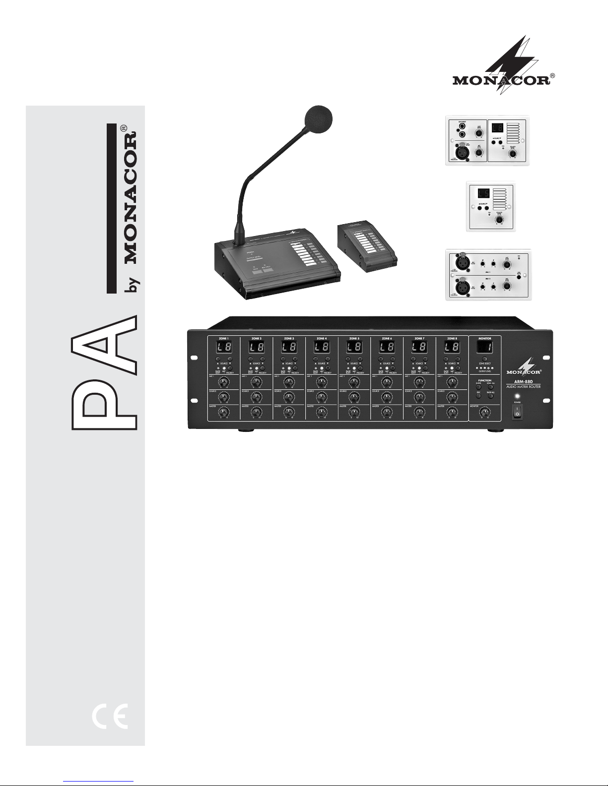
AUDIOSIGNAL-MATRIX-ROUTER
AUDIO SIGNAL MATRIX ROUTER
BEDIENUNGSANLEITUNG
INSTRUCTION MANUAL
MODE D’EMPLOI
ISTRUZIONI PER L’USO
MANUAL DE INSTRUCCIONES
INSTRUKCJA OBSŁUGI
VEILIGHEIDSVOORSCHRIFTEN
SIKKERHEDSOPLYSNINGER
SÄKERHETSFÖRESKRIFTER
TURVALLISUUDESTA
ARM-880
Bestellnummer 17.3800
ARM-880RC
Bestellnummer 17.3810
ARM-880RCE
Bestellnummer 17.3820
ARM-880WP1
Bestellnummer 17.3830
ARM-880WP2
Bestellnummer 17.3840
ARM-880WP3
Bestellnummer 17.3850
Page 2

2
Bevor Sie einschalten …
Wir wünschen Ihnen viel Spaß mit Ihrem neuen Gerät
von MONACOR. Bitte lesen Sie diese Bedienungsanleitung vor dem Betrieb gründlich durch. Nur so lernen Sie
alle Funktionsmöglichkeiten kennen, vermeiden Fehlbedienungen und schützen sich und Ihr Gerät vor eventuellen Schäden durch unsachgemäßen Gebrauch. Heben
Sie die Anleitung für ein späteres Nachlesen auf.
Der deutsche Text beginnt auf der Seite 4.
Before switching on …
We wish you much pleasure with your new MONACOR
unit. Please read these operating instructions carefully
prior to operating the unit. Thus, you will get to know all
functions of the unit, operating errors will be prevented,
and yourself and the unit will be protected against any
damage caused by improper use. Please keep the oper ating instructions for later use.
The English text starts on page 10.
Avant toute installation …
Nous vous souhaitons beaucoup de plaisir à utiliser cet
appareil MONACOR. Lisez ce mode dʼemploi entièrement avant toute utilisation. Uniquement ainsi, vous pourrez apprendre lʼensemble des possibilités de fonctionnement de lʼappareil, éviter toute manipulation erronée et
vous protéger, ainsi que lʼappareil, de dommages éventuels engendrés par une utilisation inadaptée. Conservez
la notice pour pouvoir vous y reporter ultérieurement.
La version française se trouve page 16.
Prima di accendere …
Vi auguriamo buon divertimento con il vostro nuovo
apparecchio di MONACOR. Leggete attentamente le
istruzioni prima di mettere in funzione lʼapparecchio.
Solo così potete conoscere tutte le funzionalità, evitare
comandi sbagliati e proteggere voi stessi e lʼapparecchio
da eventuali danni in seguito ad un uso improprio. Conservate le istruzioni per poterle consultare anche in
futuro.
Il testo italiano inizia a pagina 22.
D
A
CH
GB
Voor u inschakelt …
Wij wensen u veel plezier met uw nieuwe apparaat van
MONACOR. Lees de veiligheidsvoorschriften grondig
door, alvorens het apparaat in gebruik te nemen. Zo
behoedt u zichzelf en het apparaat voor eventuele
schade door ondeskundig gebruik. Bewaar de handleiding voor latere raadpleging.
De veiligheidsvoorschriften vindt u op pagina 40.
Før du tænder …
Tillykke med dit nye MONACOR produkt. Læs sikkerhedsanvisningerne nøje før ibrugtagning, for at beskytte
Dem og enheden mod skader, der skyldes forkert brug.
Gem venligst denne betjeningsvejledning til senere brug.
Sikkerhedsanvisningerne findes på side 40.
Innan du slår på enheten …
Vi önskar dig mycket glädje med din nya MONACOR
produkt. Läs igenom säkerhetsföre skrifterna innan en heten tas i bruk för att undvika skador till följd av felaktig
hantering. Behåll instruktionerna för framtida bruk.
Säkerhetsföreskrifterna återfinns på sidan 41.
Ennen kytkemistä …
Toivomme Sinulle paljon miellyttäviä hetkiä uuden
MONACOR laitteen kanssa. Ennen laitteen käyttöä pyydämme Sinua huolellisesti tutustumaan turvallisuusohjeisiin. Näin vältyt vahingoilta, joita virheellinen laitteen
käyttö saattaa aiheuttaa. Ole hyvä ja säilytä käyttöohjeet
myöhempää tarvetta varten.
Turvallisuusohjeet löytyvät sivulta 41.
F
B
CH
I
Antes de la utilización …
Le deseamos una buena utilización para su nue vo aparato MONACOR. Por favor, lea estas in s trucciones de
uso atentamente antes de ha cer funcionar el aparato. De
esta manera conocerá todas las funciones de la unidad,
se pre vendrán errores de operación, usted y el apa rato
estarán protegidos en contra de todo daño cau sado por
un uso inadecuado. Por favor, guarde las instrucciones
para una futura utilización.
La versión española comienza en la página 28.
E
NL
Przed uruchomieniem …
Życzymy zadowolenia z nowego produktu MONACOR.
Dzięki tej instrukcji obsługi będą państwo w stanie
poznać wszystkie funkcje tego urządzenia. Stosując się
do instrukcji unikną państwo błędów i ewentualnego
uszkodzenia urządzenia na skutek nieprawidłowego
użytkowania. Prosimy zachować instrukcję.
Tekst polski zaczyna się na stronie 34.
PL
DK
S
FIN
B
Page 3
3
¨
POWER
0
10
0
10
0
10
ZONE SELECT
OUTPUT LEVEL
0
10
PAGE ALL
ENTER
BGM ALL
ESC
MONITOR
SOURCE
PAGE
BUSY
MIC
1 PRIORITY
MIC 1
SOURCE
MASTER
AUDIO MATRIX ROUTER
0
10
0
10
0
10
SOURCE
PAGE
BUSY
MIC
1 PRIORITY
MIC 1
SOURCE
MASTER
0
10
0
10
0
10
SOURCE
PAGE
BUSY
MIC
1 PRIORITY
MIC 1
SOURCE
MASTER
0
10
0
10
0
10
SOURCE
PAGE
BUSY
MIC
1 PRIORITY
MIC 1
SOURCE
MASTER
0
10
0
10
0
10
SOURCE
PAGE
BUSY
MIC
1 PRIORITY
MIC 1
SOURCE
MASTER
0
10
0
10
0
10
SOURCE
PAGE
BUSY
MIC
1 PRIORITY
MIC 1
SOURCE
MASTER
0
10
0
10
0
10
SOURCE
PAGE
BUSY
MIC
1 PRIORITY
MIC 1
SOURCE
MASTER
0
10
0
10
0
10
SOURCE
PAGE
BUSY
MIC
1 PRIORITY
MIC 1
SOURCE
MASTER
0
10
0
10
0
10
SOURCE
PAGE
BUSY
MIC
1 PRIORITY
MIC 1
SOURCE
MASTER
230V~/50Hz
12345678G
COMMON
ALERT
EVAC
GND
EMC IN
TONE
OUTPUT
EMC
INPUT
GAIN GAIN GAIN GAIN
EXTENSION LINK IN
EXTENSION LINK OUT
775mV/ 10k½
LLLL
RRRR
GND
LIN
E
M
IC
PHAN
TOM
195mV—2V /22k
½
GAIN
HF
LF
PAGE
+10
-
10
+10
-
10
GND
OUTPUT
0.775V/
600
½
300mV—1.1V/10k
½
dB
dB
GND
LINE
M
IC
PHANTO
M
GND
LINE
M
IC
PHANTOM
GND
LINE
M
IC
PHAN
TO
M
LINE 350mV, MIC 5mV
GAIN GAIN
GAIN LF HF
-
8dB+8-8dB+8
5mV-300mV/ 600
½
REMOTE
WALL CTRL
ON OFF
REM.SOURCE 1
GAIN
MASTER
SLAVE
123
INPUT VOLTAGE SELECTOR
24V /2A
BATT SUPPLY
GND
GAIN
HF
LF
PAGE
+10
-
10
+10
-
10
GND
OUTPUT
0.775V/
600
½
300mV—1.1V/10k
½
dB
dB
REMOTE
WALL CTRL
ON OFF
REM.SOURCE 2
GAIN
GND
GAIN
HF
LF
PAGE
+10
-
10
+10
-
10
GND
OUTPUT
0.775V/
600
½
300mV—1.1V/10k
½
dB
dB
REMOTE
WALL CTRL
ON OFF
REM.SOURCE 3
GAIN
GND
GAIN
HF
LF
PAGE
+10
-
10
+10
-
10
GND
OUTPUT
0.775V/
600
½
300mV—1.1V/10k
½
dB
dB
REMOTE
WALL CTRL
ON OFF
REM.SOURCE 4
GAIN
GND
GAIN
HF
LF
PAGE
+10
-
10
+10
-
10
GND
OUTPUT
0.775V/
600
½
300mV—1.1V/10k
½
dB
dB
REMOTE
WALL CTRL
ON OFF
REM.SOURCE 5
GAIN
GND
GAIN
HF
LF
PAGE
+10
-
10
+10
-
10
GND
OUTPUT
0.775V/
600
½
300mV—1.1V/10k
½
dB
dB
REMOTE
WALL CTRL
ON OFF
REM.SOURCE 6
GAIN
GND
GAIN
HF
LF
PAGE
+10
-
10
+10
-
10
GND
OUTPUT
0.775V/
600
½
300mV—1.1V/10k
½
dB
dB
REMOTE
WALL CTRL
ON OFF
REM.SOURCE 7
GAIN
GND
GAIN
HF
LF
PAGE
+10
-
10
+10
-
10
GND
OUTPUT
0.775V/
600
½
300mV—1.1V/10k
½
dB
dB
REMOTE
WALL CTRL
ON OFF
REM.SOURCE 8
GAIN
GND
GAIN
HF
LF
PAGE
+10
-
10
+10
-
10
GND
OUTPUT
0.775V/
600
½
300mV—1.1V/10k
½
dB
dB
REMOTE
WALL CTRL
ON OFF
REM.SOURCE . .
GAIN
GND
ZONE SELECT
OUTPUT LEVEL
0
10
PAGE ALL
ENTER
BGM ALL
ESC
MONITOR
USE ONLY WITH A 250V FUSE
CONTACT CLOSURE
27 28 29 30 31 32 33 34 35 36 37 38 39 40 41 42
43 44 45 46 47 48 49 50
3
ARM-880
MIC
+12V PHANTOM
¨
ARM-880RC
PA REMOTE DESK MICROPHONE
POWER
CONNECT TO
ARM-880
24V
010 010
2-TONE
OFF
4-TONE
CHIMEMIC
ALL CALLTALK
POWER
OUTPUT LEVEL
SPEAKER ZONES
ARM-880RCE
EXTENSION MODULE
FOR ARM-880RC
SPEAKER ZONES
1234
DIP ON
MIC
LEVEL
LINE
LEVEL
LINE INPUT
MIC
INPUT
+15V
PHANTOM
SOURCE
ON
1
2
3
4
5
6
7
8
SOURCE
LEVEL
0
10
0
10
0
10
PUSH
SOURCE
ON
1
2
3
4
5
6
7
8
MIC
LEVEL
HF LF
HF LF
MIC
LEVEL
LINE
MUTE
ON
MIC 2
MIC 1
MIC
INPUT
MIC
INPUT
+15V
PHANTOM
+15V
PHANTOM
0
10
SOURCE
LEVEL
0
10
0
10
PUSH
PUSH
51 52 53 54 55 56 57 56 57 58 67 68 69 70 71
ARM-880RC
59 60 61 62 63 64 65 66
ARM-880RCE
ARM-880WP1
ARM-880WP2
ARM-880WP3
12
4
5
6
7
9
10
17
18
25
26
24
23
11
12
13
14
15
8
16
22
21
20
19
63 64 65 66
Page 4

4
D
A
CH
Inhalt
1 Übersicht der Bedienelemente
und Anschlüsse . . . . . . . . . . . . . . . . . . 4
1.1 Vorderseite . . . . . . . . . . . . . . . . . . . . . . . 4
1.2 Rückseite . . . . . . . . . . . . . . . . . . . . . . . . 4
1.3 Zubehör . . . . . . . . . . . . . . . . . . . . . . . . . 5
1.3.1 ARM-880RC und ARM-880RCE . . . . . 5
1.3.2 ARM-880WP1 und ARM-880WP2 . . . 5
1.3.3 ARM-880WP3 . . . . . . . . . . . . . . . . . . . 5
2 Hinweise für den sicheren Gebrauch .5
3 Einsatzmöglichkeiten . . . . . . . . . . . . . . 6
4 Matrix-Router aufstellen und
anschließen . . . . . . . . . . . . . . . . . . . . . . 6
4.1 Audiogeräte mit Line-Ausgang . . . . . . . . 6
4.2 Mikrofone . . . . . . . . . . . . . . . . . . . . . . . . 6
4.3 Alarmeingänge . . . . . . . . . . . . . . . . . . . . 6
4.4 Wandmodule . . . . . . . . . . . . . . . . . . . . . 6
4.5 Leistungsverstärker oder Aktivbox . . . . . 6
4.6 Erweiterung der Anlage
auf bis zu 32 Zonen . . . . . . . . . . . . . . . . 6
4.7 Strom- und Notstromversorgung . . . . . . 7
5 Grundeinstellungen . . . . . . . . . . . . . . . 7
6 Bedienung . . . . . . . . . . . . . . . . . . . . . . . 7
6.1 Matrix-Router ARM-880 . . . . . . . . . . . . . 7
6.1.1 Signalquellen für die Zonen wählen . . 7
6.1.2 Durchsagen über MIC 1 . . . . . . . . . . . 7
6.1.3 Abhören der Zonen über den
Lautsprecher . . . . . . . . . . . . . . . . . . . . 8
6.2 Kommandomikrofon ARM-880RC . . . . . 8
6.3 Wandmodule . . . . . . . . . . . . . . . . . . . . . 8
6.3.1 ARM-880WP1 und ARM-880WP2 . . . 8
6.3.2 ARM-880WP3 . . . . . . . . . . . . . . . . . . . 8
7 Technische Daten . . . . . . . . . . . . . . . . . 9
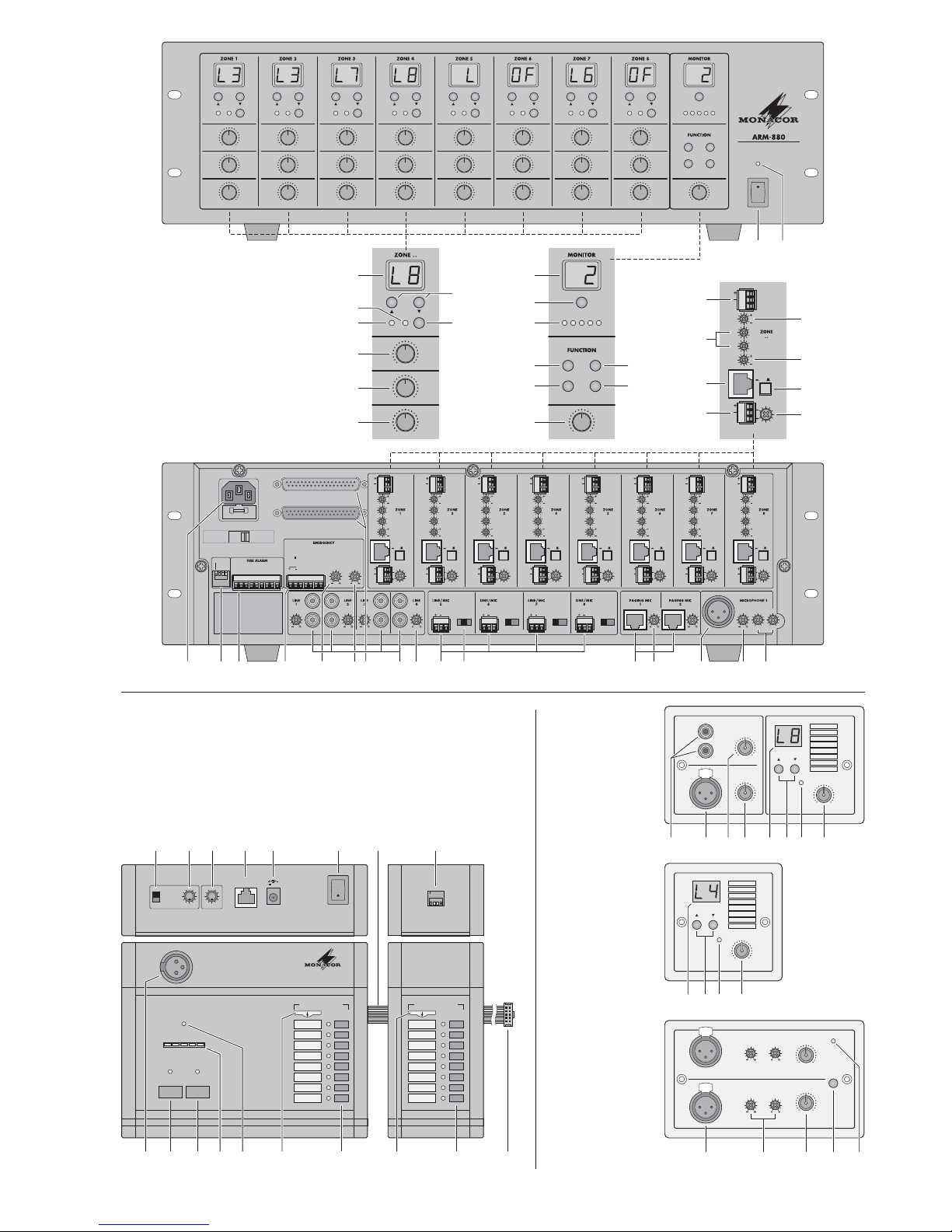
Auf der ausklappbaren Seite 3 finden Sie
alle beschriebenen Bedienelemente und An schlüsse.
1 Übersicht der Bedienelemente
und Anschlüsse
1.1 Vorderseite
1 Ein-/Ausschalter
2 Betriebsanzeige
Für jede der acht Beschallungszonen sind separate Anzeigen und Bedienelemente vorhanden,
mit denen sich die Zonen unterschiedlich konfigurieren lassen:
3 Display zur Anzeige der mit den Tasten
SOURCE (9) gewählten Signalquelle:
L 1 – L 8 = Signale der Eingänge LINE 1 – 4
(34) und LINE/ MIC 5 – 8 (36)
L = Signal vom zusätzlichen Eingang (22)
oder vom angeschlossenen Wandmodul
(ARM-880WP1, ARM-880WP3)
OF = keines dieser Signale angewählt (OFF)
4 Anzeige MIC 1: leuchtet, wenn ein an der
Buchse MICROPHONE 1 (40) angeschlossenes Mikrofon Vorrang vor anderen Signalquellen hat (Auto-Talkover); schaltbar mit der
Taste PRIORITY (10)
5 Anzeige PAGE BUSY: leuchtet, wenn eine
Durchsage über ein angeschlossenes Kommandomikrofon ARM-880RC erfolgt
6 Mischregler MIC 1 für den Pegel eines an der
Buchse MICROPHONE 1 (40) angeschlossenen Mikrofons
7 Mischregler
SOURCE
für den Pegel
der mit
den Tasten SOURCE (9) ausgewählten Signalquelle
8 Regler MASTER für die Gesamtlautstärke der
Zone
9 Tasten SOURCE zur Auswahl der Signalquelle
(Position 3)
Nach der Auswahl innerhalb von 10 Sek. die
Taste ENTER (14) zur Bestätigung drücken.
10 Taste PRIORITY, um einem an der Buchse
MICROPHONE 1 (40) angeschlossenen Mi krofon Vorrang vor anderen Signalquellen zu
geben (Auto-Talkover); bei eingeschalteter
Vorrangfunktion leuchtet die Anzeige MIC 1 (4)
Im Bedienfeld MONITOR erfolgen u. a. die Einstellungen zum Abhören der Beschallungszonen
über den eingebauten Lautsprecher:
11 Display zur Anzeige der mit der Taste ZONE
SELECT (12) gewählten Zone
12 Taste ZONE SELECT zum Wählen der Zone,
die abgehört werden soll
Nach der Auswahl innerhalb von 10 Sek. die
Taste ENTER (14) zur Bestätigung drücken.
13 Pegelanzeige für das Ausgangssignal der
gewählten Zone
14 Taste ENTER zur Bestätigung einer Auswahl
mit den Tasten SOURCE (9), ZONE SELECT
(12) oder BGM ALL (17)
15 Taste ESC, um eine mit den Tasten SOURCE
(9), ZONE SELECT (12) oder BGM ALL (17)
begonnene Auswahl abzubrechen
(Beendet das Blinken der Displays und schaltet auf die vorherige Einstellung zurück.)
16 Lautstärkeregler MONITOR für den einge-
bauten Lautsprecher
17 Taste BGM ALL, um für alle Zonen gemein-
sam die gleiche Signalquelle anzuwählen
Nach der Auswahl innerhalb von 10 Sek. die
Taste ENTER (14) zur Bestätigung drücken.
18 Taste PAGE ALL, um für alle Zonen gemein-
sam einem an der Buchse MICROPHONE 1
(40) angeschlossenen Mikrofon Vorrang vor
anderen Signalquellen zu geben
1.2 Rückseite
Die grünen Schraubklemmen (19, 22, 29, 30, 36)
lassen sich zur leichteren Handhabung beim An schließen aus ihren Steckverbindungen herausziehen.
19 Ausgang für das Audiosignal der jeweiligen
Beschallungszone zum Anschluss an einen
Leistungsverstärker
20 Klangregler für die jeweilige Zone
21 Anschluss für ein Wandmodul
(ARM-880WP…)
22 zusätzlicher Eingang für ein Audiosignal (Line-
Pegel), das nur auf die zugehörige Zone ge langt
23 Regler GAIN zur Anpassung des Zonenaus-
gangspegels an die Eingangsempfindlichkeit
des angeschlossenen Verstärkers oder zum
Einstellen der maximal zulässigen Zonenlautstärke
24 Regler PAGE zum Einstellen der Lautstärke
in jeder Zone für die Signale der angeschlossenen Kommandomikrofone
[Buchsen PAGING MIC 1 und 2 (38)]
25 Taste REMOTE WALL CTRL
Taste gedrückt: Die Signalquelle für die Zone
kann nur über ein angeschlossenes Wandmodul gewählt werden.
Taste nicht gedrückt: Die Signalquelle kann
nur am Matrix-Router gewählt werden.
26 Pegelregler für das Audiosignal des zusätz -
lichen Eingangs (22) und für das Audiosignal
eines an der Buchse (21) angeschlossenen
Wandmoduls
27 Netzbuchse zum Anschluss an eine Steck-
dose (230 V~/50Hz) über das beiliegende
Netzkabel
Darunter befindet sich die Halterung für die
Netzsicherung. Eine geschmolzene Sicherung nur durch eine gleichen Typs ersetzen.
28 DIP-Schalter zum Festlegen von Hauptgerät
und Nebengeräten, wenn mehrere Geräte
ARM-880 zusammengeschaltet werden, um
zusätzliche Beschallungszonen zu erhalten
(
Kap. 4.6)
WICHTIG! Am Hauptgerät oder wenn nur ein
ARM-880 in der Anlage eingesetzt ist, muss
der Schalter MASTER in der unteren Position
ON stehen und alle anderen Schalter in der
oberen Position. Anderenfalls werden die
Signale der Eingänge LINE 1 – 4 (34) und
LINE / MIC 5 – 8 (36) nicht auf die Zonenausgänge (19) geleitet.
29 (Feuer-) Alarmeingänge
Wird der Kontakt für eine Zone mit dem Kontakt „G“ verbunden, ertönt in der Zone ein
(Feuer-) Alarmsignal und im Display (3) blinkt
die Anzeige AL. Die Alarmlautstärke lässt
sich mit dem Regler TONE OUTPUT (31)
einstellen.
Zusätzlich oder alternativ kann auch ein Signal, das am Kontakt EMC IN der Klemme
EMERGENCY (30) anliegt, in die Zone geleitet werden. Die Signallautstärke lässt sich mit
dem Regler EMC INPUT (32) einstellen.
30 Klemmleiste EMERGENCY
Kontakte BATT SUPPLY + und
-
für eine
24-V-Notstromversorgung
Page 5
D
A
CH
5
Kontakte COMMON und ALERT verbunden:
ändert das Alarmsignal in einen pulsierenden
Signalton
Kontakte COMMON und EVAC verbunden:
ändert das Alarmsignal in ein anschwellendes Sirenensignal
Kontakte EMC IN und GND für ein Signal,
das bei einer Alarmauslösung auf die zugehörige Zone geleitet wird
31 Regler TONE OUTPUT für die Lautstärke
des Alarmsignals
32 Regler EMC INPUT für die Lautstärke des
Signals am Kontakt EMC IN der Klemme
EMERGENCY (30)
33 D-Sub-Anschlüsse (DC-37) zum Zusammen-
schalten mehrerer ARM-880, um zusätzliche
Beschallungszonen zu erhalten (max. 32),
Kap. 4.6
34 Stereo-Eingänge LINE 1 – 4 zum Anschluss
von Audiogeräten mit Line-Ausgang (z. B.
Radio, MP3- / CD-Spieler, Tape-Deck)
35 Regler GAIN zur Eingangspegelanpassung
der Eingänge LINE 1 – 4
36 Audio-Eingänge LINE / MIC 5 – 8 zum An -
schluss von Audiogeräten mit Line-Ausgang
oder zum Anschluss von Mikrofonen
37 Umschalter für die Eingänge LINE / MIC5 – 8
LINE = für ein Audiogerät mit Line-Ausgang
MIC = für ein Mikrofon
PHANTOM = für ein Mikrofon, das eine Phan-
tomspeisung (46 V) benötigt
38 RJ-45-Buchsen PAGING MIC 1 und 2 zum
Anschluss von zwei Kommandomikrofonen
ARM-880RC
39 Regler GAIN für die Empfindlichkeit der Ein-
gänge PAGING MIC 1 und 2 (38)
40 Buchse MICROPHONE 1 für ein Mikrofon
Das Mikrofonsignal kann in allen Zonen ge hört werden: Mit den Reglern MIC 1 (6) einstellbar.
41 Regler GAIN für die Empfindlichkeit des Ein-
gangs MICROPHONE 1 (40)
42 Klangregler HF (Höhen) und LF (Tiefen) für
das an der Buchse (40) angeschlossene
Mikrofon
1.3 Zubehör
Die Geräte der Abbildungen 2 – 6 sind als Zubehör erhältlich und gehören nicht zum Lieferumfang des Matrix-Routers ARM-880.
1.3.1 ARM-880RC und ARM-880RCE
Kommandomikrofon und Erweiterungsmodul
43 Gong-Schalter CHIME
2-TONE = 2-Ton-Gong
OFF = kein Gong beim Drücken der Taste
TALK (52)
4-TONE = 4-Ton-Gong
44 Regler CHIME für die Gonglautstärke
45 Regler MIC für die Mikrofonlautstärke
46 Buchse CONNECT TO ARM-880 zum An -
schluss des Mikrofons an die Buchse
PAGING MIC 1 oder 2 (38)
47 Buchse 24 V zum Anschluss des beiliegen-
den Netzgeräts
Das Netzgerät ist nur erforderlich, wenn das
Verbindungskabel zum Matrix-Router länger
als 50 m ist.
48 Ein- /Ausschalter POWER
49 Verbindungskabel für ein eventuelles Erwei-
terungsmodul ARM-880RCE (
Kap. 4.6)
50 DIP-Schalter zum Adressieren des Erweite-
rungsmoduls
Schalter 1 auf ON für Modul 1
Schalter 2 auf ON für Modul 2
Schalter 3 auf ON für Modul 3
51 Buchse MIC zum Einstecken des beiliegen-
den Schwanenhalsmikrofons
52 Sprechtaste TALK
53 Taste ALL CALL für Durchsagen in allen
Zonen
54 Anzeige für den Ausgangspegel
55 Betriebsanzeige POWER
56 herausziehbares Etikett zur Beschriftung der
Zonen
57 Tasten mit Kontroll-LED zum Einschalten der
Zonen, in denen die Durchsage zu hören sein
soll
58 Verbindungsstecker für das nächste Erweite-
rungsmodul
1.3.2 ARM-880WP1 und ARM-880WP2
Wandmodule zur Fernsteuerung einer Zone,
ARM-880WP1 zusätzlich zur Ferneinspeisung
von Audiosignalen
59 Cinch-Buchsen LINE INPUT zum Einspeisen
eines Line-Signals, das nur auf die zugehörige Zone gelangt
60 XLR-Buchse MIC INPUT zum Anschluss
eines Mikrofons*, dessen Signale nur in der
zu gehörigen Zone gehört werden können
61 Regler LINE LEVEL für die Lautstärke eines
an den Buchsen LINE INPUT (59) angeschlossenen Audiogeräts
62 Regler MIC LEVEL für die Lautstärke eines
an der Buchse MIC INPUT (60) angeschlossenen Mikrofons
63 Display zur Anzeige der mit den Tasten
SOURCE (64) gewählten Signalquelle
(siehe auch Position 3)
64
Tasten SOURCE zur Auswahl der Signalquelle
65 Betriebsanzeige ON
66 Regler SOURCE LEVEL für die Zonenlaut-
stärke
Am ARM-880 den zugehörigen Regler MASTER (8) auf die maximal zulässige Zonenlautstärke einstellen.
1.3.3 ARM-880WP3
Wandmodul zur Einspeisung der Signale von
zwei Mikro fonen in eine Zone
67 XLR-Buchsen zum Anschluss von zwei Mikro-
fonen*
68 Klangregler HF (Höhen) und LF (Tiefen) für
die angeschlossenen Mikrofone
69 Lautstärkeregler für die angeschlossenen
Mikrofone
70 Taste LINE MUTE: schaltet die am ARM-880
angewählte Signalquelle stumm, damit nur
die Mikrofonsignale des Wandmoduls zu
hören sind
71 Betriebsanzeige ON
* Vorsicht! Kein Mikrofone mit asymmetrischem Aus-
gang anschließen. Diese können beschädigt werden,
weil stets eine 15-V-Phantomspannung an den Buchsen anliegt.
2 Hinweise für den
sicheren Gebrauch
Das Gerät entspricht allen relevanten Richtlinien
der EU und ist deshalb mit gekennzeichnet.
Beachten Sie auch unbedingt die folgenden
Punkte:
G
Das Gerät ist nur zur Verwendung im Innenbe reich geeignet. Schützen Sie es vor Tropfund Spritzwasser, hoher Luftfeuchtigkeit und
Hitze (zulässiger Einsatztemperaturbereich
0 – 40°C).
G
Stellen Sie keine mit Flüssigkeit gefüllten Ge fäße, z. B. Trinkgläser, auf das Gerät.
G
Nehmen Sie das Gerät nicht in Betrieb und
ziehen Sie sofort den Netzstecker aus der
Steckdose,
1. wenn sichtbare Schäden am Gerät oder am
Netzkabel vorhanden sind,
2. wenn nach einem Sturz oder Ähnlichem der
Verdacht auf einen Defekt besteht,
3. wenn Funktionsstörungen auftreten.
Geben Sie das Gerät in jedem Fall zur Reparatur in eine Fachwerkstatt.
G
Ziehen Sie den Netzstecker nie am Kabel aus
der Steckdose, fassen Sie immer am Stecker
an.
G
Verwenden Sie für die Reinigung nur ein trockenes, weiches Tuch, niemals Wasser oder
Chemikalien.
G
Wird das Gerät zweckentfremdet, nicht richtig
angeschlossen, falsch be dient oder nicht fachgerecht repariert, kann keine Haftung für
daraus resultierende Sach- oder Personenschäden und keine Garantie für das Gerät
übernommen werden.
Soll das Gerät endgültig aus dem Be trieb genommen werden, übergeben
Sie es zur umweltgerechten Entsorgung einem örtlichen Recyclingbetrieb.
WARNUNG Das Gerät wird mit lebensge -
fährlicher Netzspannung versorgt.
Nehmen Sie deshalb nie selbst
Eingriffe am Gerät vor. Durch un sachgemäßes Vorgehen besteht
die Gefahr eines elektrischen
Schlages.
Page 6

3 Einsatzmöglichkeiten
Der ARM-880 ist ein Audiosignal-Matrix-Router,
mit dem acht verschiedene Audioquellen (Mikrofone, MP3 / CD-Spieler, Tuner, PC usw.) beliebig
auf acht Beschallungszonen geleitet werden
können. Durch Zusammenschalten von vier
ARM-880 lässt sich die Anlage auf 32 Zonen
erweitern. Für jede Zone wird ein Leistungsverstärker für die Lautsprecher benötigt.
Für weitere Funktionen sind zahlreiche An schlüsse vorhanden:
– 2 Eingänge für die Kommandomikrofone
ARM-880RC, mit denen Durchsagen auf nur
bestimmte Zonen oder auf alle Zonen erfolgen
können
– 1 Anschluss pro Zone für ein Wandmodul
ARM-880WP… zur Fernsteuerung der Zone
und / oder zur Einspeisung eines Audiosignals
für die Zone
– 1 zusätzlicher Eingang pro Zone für ein Audio-
signal, das nur auf die zugehörige Zone geleitet wird
– 1 Mikrofoneingang, dessen Signal auf alle
Zonen geleitet werden kann, mit einschalt barer Vorrangfunktion
– 1 Alarmeingang pro Zone zum Auslösen eines
Alarmsignals in der Zone oder zum Durchschalten eines separat eingespeisten Audiosignals in die Zone
– Anschlüsse für eine 24-V-Notstromversor -
gung
4 Matrix-Router aufstellen
und anschließen
Der ARM-880 ist für den Einschub in ein Rack
für Geräte mit einer Breite von 482 mm (19″)
vorgesehen, kann aber auch als Tischgerät verwendet werden. Für den Einbau in ein Rack werden 3 HE (Höheneinheiten) = 133 mm benötigt.
Vor dem Anschließen von Geräten oder dem
Ändern bestehender Anschlüsse den MatrixRouter und die anzuschließenden Geräte ausschalten. Alle Anschlüsse sollten nur durch eine
qualifizierte Fachkraft vorgenommen werden.
Die grünen Schraubklemmen (19, 22, 29,
30, 36) lassen sich zur leichteren Handhabung
beim Anschließen aus ihren Steckverbindungen
herausziehen.
4.1 Audiogeräte mit Line-Ausgang
Um Signale von Audiogeräte mit Line-Ausgang
(z. B. Radio, MP3- / CD-Spieler, Tape-Deck, PC)
beliebig auf die Beschallungszonen leiten zu
können, die Eingänge LINE 1 – 4 (34) und LINE /
MIC 5 – 8 (36) verwenden. Für die Eingänge
LINE 1 – 4 sind Cinch-Buchsen vorhanden und
für die Eingänge LINE / MIC 5 – 8 Schraubklemmen. Beim Anschluss eines Audiogerätes an die
Schraubklemmen den zugehörigen Schalter
(37) in die Position LINE stellen.
Sollen die Signale eines Audiogeräts ausschließlich auf eine bestimmte Zone geleitet
werden, kann auch der für jede Zone vorhandene Schraubklemmen-Zusatzeingang (22) verwendet werden.
Die Schraubklemmen sind für symmetrische
Signale ausgelegt. Für einen asymmetrischen
Anschluss das Signal auf den Kontakt + geben
und die Kontakte
-
und GND mit der Signal-
masse verbinden.
4.2 Mikrofone
Beim Anschluss von mehreren Mikrofonen können diese eine unterschiedliche Priorität erhalten, d. h. eine Durchsage über ein Mikrofon mit
hoher Priorität kann eine Durchsage über ein
Mikrofon mit niedrigerer Priorität automatisch
unterbrechen.
Höchste Priorität haben die Kommandomikrofone ARM-880RC, mit denen Durchsagen in nur
bestimmten Zonen oder in allen Zonen erfolgen
können. Zwei Kommandomikrofone lassen sich
an die Buchsen PAGING MIC 1 und 2 (38)
anschließen. Dazu wird ein Netzwerkkabel (z. B.
Cat-5-Kabel) mit RJ-45-Steckern benötigt. Die
Stromversorgung der Mikrofone erfolgt über den
Matrix-Router. Bei Kabellängen ab 50 m muss
jedoch das beiliegende Netzgerät verwendet
werden, das an die Buchse 24 V (47) angeschlossen wird.
Mittlere Priorität hat ein Mikrofon, das an die
Buchse MICROPHONE 1 (40) angeschlossen
wird. Das Mikrofonsignal lässt sich durch die
Regler MIC 1 (6) in die Zonen leiten und in der
Lautstärke einstellen. Soll es Priorität vor den
Signalen der Eingänge LINE 1 – 4 (34) und LINE /
MIC 5 – 8 (36) erhalten, nach dem Einschalten
des Matrix-Routers die Tasten PRIORITY (10)
der entsprechenden Zonen drücken. Die Funktion
kann auch für alle Zonen gleichzeitig mit der Taste
PAGE ALL (18) aktiviert und deaktiviert werden.
Hinweis: Die Prioritätseinstellung wird beim Ausschalten des Matrix-Routers nicht gespeichert und muss
nach dem Wiedereinschalten ggf. erneut erfolgen.
Niedrigste Priorität haben Mikrofone, die an
die Schraubklemmen der Eingänge LINE / MIC
5 – 8 (36) angeschlossen werden.
Die Schraubklemmen sind für symmetrische
Signale ausgelegt. Für einen asymmetrischen
Anschluss das Signal auf den Kontakt + geben
und die Kontakte
-
und GND mit der Signal-
masse verbinden.
Wenn das Mikrofon eine Phantomspeisung
(46 V) benötigt, den zugehörigen Schalter (37) in
die Position PHANTOM stellen. Bei Mikrofonen,
die keine Phantomspeisung benötigen, den
Schalter in die Position MIC schieben.
4.3 Alarmeingänge
An der Schraubklemme FIRE ALARM (29) ist für
jede Zone ein Kontakt (1 – 8) für eine Alarmauslösung vorhanden. Wird dieser Kontakt über einen
entsprechenden Schalter mit dem Kontakt „G“
verbunden, ertönt in der Zone ein (Feuer-) Alarmsignal und im Display (3) blinkt die Anzeige „AL“.
Ist das Wandmodul ARM-880WP1 oder ARM880WP2 angeschlossen, wird dort „Er“ angezeigt. Die Alarmlautstärke für alle Zonen
gemeinsam lässt sich mit dem Regler TONE
OUTPUT (31) einstellen. Das Alarmsignal hat
höchste Priorität und unterbricht alle anderen
Signale in der Zone.
Anstelle des Feueralarmsignals kann auch
ein pulsierender Signalton oder ein anschwellendes Sirenensignal ertönen. Für einen pulsierenden Signalton die Kontakte ALERT und
COMMON der Klemme EMERGENCY (30) verbinden oder für ein anschwellendes Sirenensignal die Kontakte EVAC und COMMON.
Zusätzlich oder alternativ kann bei einer
Alarmauslösung ein Audiosignal mit Line-Pegel,
das auf den Kontakt EMC IN der Klemme EMERGENCY (30) gegeben wird, in die zugehörige
Zone geleitet werden. Auch dabei werden alle
anderen Signale in der Zone unterbrochen. Die
Signallautstärke für alle Zonen gemeinsam lässt
sich mit dem Regler EMC INPUT (32) einstellen.
4.4 Wandmodule
Jede Beschallungszone lässt sich durch den
Anschluss des Wandmoduls ARM-880WP1
oder ARM-880WP2 fernsteuern. Zur Ferneinspeisung eines Audiosignal in eine Zone kann
das Wandmoduls ARM-880WP1 oder ARM880WP3 verwendet werden.
Die RJ-45-Buchse „Net Interface“ auf der
Rückseite des Moduls über ein Netzwerkkabel
(z. B. Cat-5-Kabel) mit RJ-45-Steckern an die
Buchse REMOTE WALL CTRL (21) der entsprechenden Zone anschließen. Die Stromversorgung der Wandmodule erfolgt über den MatrixRouter. Bei Kabellängen ab 50 m muss jedoch
ein Netzgerät (24 V , belastbar mit 500 mA) verwendet werden, das an die Kontakte 24 V und
GND der Schraubklemme auf der Rückseite des
Moduls angeschlossen wird.
Bei den Zonen, an denen ein Wandmodul
an geschlossen ist, die Taste REMOTE WALL
CTRL (25) hineindrücken. Anderenfalls lässt
sich die Zone nicht mit dem Modul fernsteuern.
Bei den Modellen ARM-880WP1 und -WP2 wird
dann im Display (63) „OF“ angezeigt.
4.5 Leistungsverstärker oder Aktivbox
Ein symmetrisches Ausgangssignal für jede
Zone liegt an den Schraubklemmen OUTPUT
(19) an. Hier jeweils den Eingang eines Leistungsverstärkers für die Lautsprecher anschließen. Ist am Verstärker nur ein asymmetrischer
Eingang vorhanden, diesen nur an die Kontakte
+ (Signal) und GND (Masse) anschließen. Alternativ können an die Zonenausgänge auch Aktivlautsprecherboxen angeschlossen werden.
4.6 Erweiterung der Anlage
auf bis zu 32 Zonen
Reichen acht Beschallungszonen nicht aus,
kann durch Verwendung von bis zu drei weiteren
Matrix-Routern ARM-880 die Anlage auf 16, 24
oder 32 Zonen erweitert werden.
Hinweis: Die Anzahl der routfähigen Eingänge wird
damit nicht erhöht. Es lassen nur die Signale der Eingänge LINE 1 – 4 (34) und LINE / MIC 5 – 8 (36) des
Hauptgeräts auf alle verfügbaren Zonen beliebig leiten.
Jedoch können die Zusatzeingänge (22) für jede Zone
und die Alarmeingänge (29, 30) an jedem ARM-880
genutzt werden. Auch lässt sich an jede weitere Zone
ein Wandmodul anschließen.
1) Den Anschluss EXTENSION LINK OUT (33)
des Hauptgeräts (an dem alle beliebig zu verteilenden Signale anliegen) über das beiliegende Kabel mit dem Anschluss EXTENSION LINK IN eines zusätzlichen MatrixRouters ARM-880 (= Nebengerät) verbinden.
2) Am Hauptgerät muss der DIP-Schalter MAS-
TER (28) in die untere Position ON gestellt
werden. Alle anderen DIP-Schalter müssen
in der oberen Position stehen.
3) Am (ersten) Nebengerät den DIP-Schalter
SLAVE 1 in die untere Position ON stellen.
Alle anderen DIP-Schalter müssen in der
oberen Position stehen.
4) Auf gleiche Weise lässt sich am ersten
Nebengerät ein zweites anschließen und am
zweiten Nebengerät ein drittes. Am zweiten
Nebengerät den DIP-Schalter SLAVE 2 in die
untere Position stellen und am dritten Nebengerät den DIP-Schalter SLAVE 3. Alle anderen DIP-Schalter müssen in der oberen Position stehen.
5) Sind in der Anlage die Kommandomikrofone
ARM-880RC eingesetzt, müssen diese für
jedes Nebengerät mit einem Erweiterungsmodul ARM-880RCE ergänzt werden, damit
auch die zusätzlichen Zonen einzeln angewählt werden können. Das Verbindungs -
D
A
CH
6
Page 7
D
A
CH
7
kabel (49) des Kommandomikrofons an die
Buchse auf der Unterseite des Erweiterungsmoduls anschließen. Bei Bedarf den Stecker
(58) des Erweiterungsmoduls in das nächste
Erweiterungsmodul stecken.
Jedes Erweiterungsmodul mit seinen DIP-
Schaltern (50) adressieren:
4.7 Strom- und Notstromversorgung
Zum Schluss das beiliegende Netzkabel zuerst
in die Netzbuchse (27) und dann in eine Steckdose (230 V~/ 50Hz) stecken.
Soll der Matrix-Router bei einem Netzausfall
weiterarbeiten, eine 24-V-Notstromeinheit (z. B.
PA-24ESP von MONACOR) an die Kontakte
BATT SUPPLY + und
-
der Schraubklemme
EMERGENCY (30) anschließen.
5 Grundeinstellungen
Für die Inbetriebnahme folgende Grundeinstellungen am Matrix-Router vornehmen. Vorerst
das Gerät noch nicht einschalten.
1) Die DIP-Schalter (28) müssen wie folgt ein-
gestellt sein:
Hinweise: Die Schalter müssen bei ausgeschaltetem Gerät betätigt werden. Bei eingeschaltetem
Gerät erfolgt keine Funktionsänderung. Ist das
Hauptgerät falsch eingestellt, lassen sich die Signale der Eingänge LINE 1 – 4 (34) und LINE / MIC
5 – 8 (36) nicht auf die Zonenausgänge (19) leiten.
2) Bei den Zonen, an denen ein Wandmodul an -
geschlossen ist, die Taste REMOTE WALL
CTRL (25) hineindrücken.
3) Bei den Eingängen LINE / MIC 5 – 8 die Schie-
beschalter (37) in die entsprechende Position
stellen:
LINE = für ein Audiogerät mit Line-Ausgang
MIC = für ein Mikrofon
PHANTOM = für ein Mikrofon, das eine Phan-
tomspeisung (46 V) benötigt
Die weiteren Bedienschritte dienen nur als Hilfestellung, es sind auch andere Vorgehensweisen
möglich.
4) Auf der Rückseite alle Regler (20, 23, 24, 26,
31, 32, 35, 39, 41, 42) in die Mittelposition
drehen, jedoch die Regler GAIN der Eingänge, die nicht verwendet werden, ganz
nach links in die Position „
-
“ drehen.
5) Vorerst in jeder Zone die Regler MIC 1 (6)
und SOURCE (7) in die Mittelposition drehen
und den Regler MASTER (8) in die Position
„0“ drehen.
6) Zuerst die angeschlossenen Audioquellen
und den Matrix-Router einschalten, danach
die an den Zonenausgängen (19) angeschlossenen Leistungsverstärker oder Aktivlautsprecherboxen.
7) In jeder Zone von den Eingängen 1 – 8 den
anwählen, der am lautesten zu hören sein
soll: Die Taste SOURCE
▲ oder ▼ (9) so oft
drücken, bis das Display (3) die Nummer des
Eingangs anzeigt (L1 … L8). Dann innerhalb
von 10 s die Auswahl mit der Taste ENTER
(14) be stätigen. Mit dem Regler MASTER (8)
und mit dem Lautstärkeregler des Leistungsverstärkers oder der Aktivlautsprecherbox
die gewünschte Lautstärke einstellen.
Hinweis: Bei den Zonen, an denen das Wand modul ARM-880WP1 oder -WP2 angeschlossen ist,
muss der Signaleingang mit der Taste BGM ALL
(17) angewählt werden oder direkt am Modul mit
den Tasten SOURCE (64).
8) Mit den Reglern GAIN (35) der Eingänge
LINE 1 – 4 lässt sich die Eingangsempfindlichkeit an den Ausgangspegel der angeschlossenen Geräte anpassen und Lautstärkeunterschiede ausgleichen, die beim Umschalten zwischen den Eingängen auftreten.
9) Mit den Reglern GAIN (23) kann für jede Zone
der Ausgangspegel an die Eingangsempfindlichkeit des angeschlossenen Leistungsverstärkers oder der Aktivbox angepasst werden. Mit den Reglern lässt sich aber auch der
Ausgangspegel begrenzen, damit nicht versehentlich eine zu hohe Lautstärke mit den
Reglern MASTER eingestellt werden kann.
10) Den Klang für jede Zone separat mit den
Reglern (20) einstellen. Der Regler HF ist für
die Höhen und Regler LF für die Tiefen.
11) Ist ein Mikrofon an der Buchse MICROPHONE 1 (40) angeschlossen, hierüber eine
Durchsage sprechen. Mit dem Regler GAIN
(41) die Eingangsempfindlichkeit einstellen
und mit den Reglern MIC 1 (6) für jede Zone
separat die gewünschte Lautstärke für die
Durchsagen. Der Klang für die Durchsagen
lässt sich mit den Reglern LF und HF (42)
einstellen.
12) Ist ein Kommandomikrofon ARM-880RC an geschlossen:
a) Am Mikrofon vorerst die Regler CHIME
(44) und MIC (45) in die Mittelposition drehen.
b) Mit dem Schalter CHIME (43) wählen, ob
beim Drücken der Taste TALK (52) vor
einer Durchsage ein Gong ertönen soll,
und wenn ja, welcher:
2-TONE = 2-Ton-Gong
OFF = kein Gong
4-TONE = 4-Ton-Gong
c) Die Taste ALL CALL (53) drücken, sodass
eine Durchsage in allen Zonen zu hören
ist.
d) Die Taste TALK gedrückt halten, eventuell
den Gong abwarten und eine Durchsage
in das Mikrofon sprechen. Mit den Reglern
PAGE (24) am Matrix-Router für jede
Zone separat die Lautstärke der Durchsage einstellen.
e) Bei Bedarf das Verhältnis zwischen Gong-
und Durchsagenlautstärke mit den Reglern CHIME (44) und MIC (45) ändern.
f) Sind zwei Kommandomikrofone ange-
schlossen, mit den Reglern GAIN (39) das
Lautstärkeverhältnis zwischen den Mikrofonen einstellen.
g) Zum Beschriften der Zonentasten (57) ist
ein Etikett (56) vorgesehen, das bei Bedarf
herausgezogen und ausgetauscht werden
kann. Das gleiche Etikett ist auch bei den
Erweiterungsmodulen ARM-880RCE vorhanden.
13) Bei den Zonen, an denen das Wandmodul
ARM-880WP1 oder -WP3 angeschlossen ist
oder der zusätzliche Audioeingang (22) verwendet wird, ein Audiosignal auf das Wandmodul geben (
Kap. 6.3) bzw. auf den
zusätzlichen Eingang. Jeweils den Eingang
mit den Tasten SOURCE (9, 64) anwählen (im
Display angezeigt durch ein „L“). Mit dem
Regler REM. SOURCE … GAIN (26) jeweils
die Lautstärke einstellen.
14) Werden die Alarmeingänge der Schraubklemme FIRE ALARM (29) genutzt, für jede
Zone einen Alarm auslösen (den Kontakt für
eine Zone und den Kontakt G überbrücken).
Mit dem Regler TONE OUTPUT (31) für alle
Zonen eines Matrix-Routers ge meinsam die
Lautstärke des Alarmsignals einstellen und /
oder mit dem Regler EMC INPUT (32) die
Lautstärke eines Audiosignals, das am Kontakt ECM IN der Klemme EMERGENCY (30)
anliegt.
6 Bedienung
6.1 Matrix-Router ARM-880
Das Gerät mit dem Schalter POWER (1) einschalten. Die Betriebsanzeige (2) leuchtet. Die
Zonendisplays (3) zeigen für jede Zone die
gewählte Signalquelle an. Das Monitordisplay
(11) zeigt die Zone an, die zum Abhören über
den eingebauten Lautsprecher angewählt ist.
6.1.1 Signalquellen für die Zonen wählen
Bei den Zonen, an denen das Wandmodul ARM880WP1 oder ARM-880WP2 angeschlossen ist,
kann die Auswahl der Signalquelle nur direkt mit
den Tasten SOURCE (64) am Modul erfolgen.
Am Matrix-Router sind die zugehörigen Tasten
SOURCE (9) ohne Funktion.
1) Durch mehrfaches Drücken oder Gedrückthalten der Taste SOURCE
▲ oder ▼ (9) die
Signalquelle auswählen. Das Display (3)
zeigt die Quelle an:
L 1 – L 8 = Signale der Eingänge LINE 1– 4
(34) und LINE/ MIC 5 – 8 (36)
L = Signal vom zusätzlichen Eingang (22)
oder vom angeschlossenen Wandmodul
(ARM-880WP1, ARM-880WP3)
OF = keines dieser Signale angewählt (OFF)
2) Nach der Auswahl blinkt die Nummer im Display 10 Sekunden lang. In dieser Zeit die
Taste ENTER (14) drücken, um die Auswahl
zu bestätigen. Anderenfalls bleibt die vorherige Auswahl erhalten. Ein Auswahlvorgang
lässt sich vorzeitig mit der Taste ESC (15)
abbrechen.
3) Wenn für alle Zonen (auch an denen ein
Wandmodul angeschlossen ist) dasselbe
Signal ausgewählt werden soll, kann das
komfortabel mit der Taste BGM ALL (17) er folgen. Nach der Auswahl die Taste ENTER
drücken.
4) Bei Bedarf die Lautstärke der gewählten Signalquelle für jede Zone separat mit dem Regler SOURCE korrigieren.
5) Die Gesamtlautstärke des Mischsignals aus
Signalquelle und Durchsagen über MIC 1
(
Kap. 6.1.2) für jede Zone separat mit
dem Regler MASTER (16) einstellen.
Tipp: Wenn in keiner Zone die Signale der Eingänge
1 – 8 zu hören sind, die Position der DIP-Schalter (28)
überprüfen (
Kapitel 5, Bedienschritt 1).
6.1.2 Durchsagen über MIC 1
Ist ein Mikrofon an der Buchse MICROPHONE 1
(40) angeschlossen, können hierüber Durchsagen für bestimmte oder für alle Zonen erfolgen.
1) In jeder Zone separat die Lautstärke für die
Durchsagen mit dem Regler MIC 1 (6) einstellen. Die Regler der Zonen auf „0“ stellen,
in denen die Durchsagen nicht zu hören sein
sollen.
Gerät
für die
Zonen
DIP-Schalter … auf
Position ON stellen
Hauptgerät 1– 8 MASTER
Nebengerät 1 9– 16 SLAVE 1
Nebengerät 2 17 – 24 SLAVE 2
Nebengerät 3 25 – 32 SLAVE 3
Modul
für die
Zonen
DIP-Schalter Nr. x auf
Position ON stellen
1 9– 16 1
2 17 – 24 2
3 25 – 32 3
Page 8

2) Das Mikrofonsignal kann mit der für jede
Zone gewählten Signalquelle gemischt werden oder das Signal der Quelle unterbrechen
(Auto-Talkover). In den Zonen, in denen das
Signal der Quelle für eine Durchsage unterbrochen werden soll, die Taste PRIORITY
(10) drücken. Die Anzeige MIC 1 (4) leuchtet
auf. Zum Einschalten der Auto-TalkoverFunktion für alle Zonen die Taste PAGE ALL
(18) drücken.
Hinweis: Nach dem Aus- und Wiedereinschalten des
Matrix-Routers ist die Auto-Talkover-Funktion ausgeschaltet. Bei Bedarf die Funktion erneut einschalten.
6.1.3 Abhören der Zonen
über den Lautsprecher
Zur Kontrolle der Zonen oder zum Auswählen
einer Signalquelle für eine Zone lässt sich jede
der acht Zonen über den eingebauten Lautsprecher abhören. Dieser gibt dann genau die Signale
wieder, die gerade in der gewählten Zone zu
hören sind.
1) Durch mehrfaches Drücken oder Gedrückthalten der Taste ZONE SELECT (12) die
Zone auswählen. Das Display (11) zeigt die
Zonennummer an.
2) Nach der Auswahl blinkt die Nummer im Display 10 Sekunden lang. In dieser Zeit die
Taste ENTER (14) drücken, um die Auswahl
zu bestätigen. Anderenfalls bleibt die vorherige Auswahl erhalten. Ein Auswahlvorgang
lässt sich vorzeitig mit der Taste ESC (15)
abbrechen.
3) Die Abhörlautstärke mit dem Regler MONITOR (16) einstellen. Die LED-Kette OUTPUT
LEVEL (13) zeigt den Signalpegel des ge wählten Zonenausgangs (19) an.
6.2 Kommandomikrofon ARM-880RC
1) Das Mikrofon mit dem Schalter POWER (48)
einschalten. Die Betriebsanzeige POWER
(55) leuchtet.
2) Zuerst die Beschallungszonen, in denen die
Durchsage zu hören sein soll, mit den Tasten
SPEAKER ZONES (57) anwählen, ggf. auch
mit den Tasten der Erweiterungsmodule
ARM-880RCE. Um alle Zonen anzuwählen
die Taste ALL CALL (53) drücken. Die angewählten Zonen werden jeweils durch eine
blau leuchtende LED angezeigt und lassen
sich auch mit der zugehörigen Taste oder der
Taste ALL CALL wieder abwählen.
Erfolgt von einem zweiten Kommando mikrofon eine Durchsage, leuchten die LEDs
der Zonen orange, in denen die Durchsage
zu hören ist. Diese Zonen können dann nicht
angewählt werden.
3) Für eine Durchsage die Taste TALK (52)
gedrückt halten, eventuell den Gong abwarten und dann sprechen. Blinkt die LED der
Taste TALK, ist keine Zone angewählt.
4) Das Mikrofonsignal wird von der LED-Kette
OUTPUT LEVEL (54) angezeigt. Die rote
LED sollte nur kurz aufleuchten. Leuchtet sie
länger, leiser sprechen, den Abstand zum
Mikrofon vergrößern oder den Regler MIC
(45) entsprechend nach links drehen.
Ist die Durchsage zu leise, den Regler entsprechend nach rechts drehen, lauter sprechen oder den Abstand zum Mikrofon verringern.
Hinweis: Die Durchsagen von einem Kommando mikrofon haben Vorrang vor anderen Signalquellen und
unterbrechen in den gewählten Zonen deren Signale.
Nur Alarmsignale haben eine noch höhere Priorität
(
Kapitel 4.3).
6.3 Wandmodule
6.3.1 ARM-880WP1 und ARM-880WP2
Sobald der Matrix-Router eingeschaltet ist,
leuchtet am Modul die Betriebsanzeige (65) und
das Display (63) zeigt die gewählte Signalquelle
an:
L 1 – L 8 = Signale der Eingänge LINE 1– 4 (34)
und LINE/ MIC 5 – 8 (36)
L = Signal vom zusätzlichen Eingang (22) oder
vom Wandmodul (
Bedienschritt 3)
OF = keines dieser Signale angewählt (OFF)
1) Um eine andere Signalquelle einzuschalten,
die Taste SOURCE
▲ oder ▼ (64) mehrfach
drücken oder gedrückt halten.
2) Die gewünschte Lautstärke mit dem Regler
SOURCE LEVEL (66) einstellen. Lässt sich
die Lautstärke nicht hoch genug einstellen,
am Matrix-Router den zugehörigen Regler
SOURCE (7) und / oder MASTER (8) entsprechend aufdrehen.
3) An das Modul ARM-880WP1 lässt sich ein
Mikrofon* an die Buchse MIC INPUT (60)
anschließen und ein Gerät mit Line-Ausgang
an die Cinch-Buchsen LINE INPUT (59), um
deren Signale in der zugehörigen Zone hören
zu können.
a) Mit der Taste SOURCE
▲ oder ▼ die Dis-
playanzeige auf „L“ schalten. Damit sind
die Buchsen LINE INPUT und MIC INPUT
angewählt.
b) Den Regler SOURCE LEVEL ungefähr in
die Mittelposition drehen und den Regler
LINE LEVEL (61) für das angeschlossene
Audiogerät und / oder den Regler MIC
LEVEL (62) für das Mikrofon soweit aufdrehen, dass die Signale gut zu hören
sind. Wenn ein Eingang nicht angeschlossen ist, den zugehörigen Regler auf „0“
drehen.
c) Die endgültige Lautstärke mit dem Regler
SOURCE LEVEL einstellen.
6.3.2 ARM-880WP3
Sobald der Matrix-Router eingeschaltet ist,
leuchtet am Modul die Betriebsanzeige (71).
1) An die Buchsen MIC INPUT (67) lassen sich
zwei Mikrofone* anschließen, um deren Signale in der zugehörigen Zone hören zu können.
2) Mit den Reglern MIC LEVEL (69) die Lautstärke für die Mikrofone einstellen. Wenn ein
Mikrofoneingang nicht angeschlossen ist,
den zugehörigen Regler auf „0“ drehen.
3) Wenn am Matrix-Router für die zugehörige
Zone eine Signalquelle angewählt ist, lassen
sich die Mikrofonsignale mit der Signalquelle
mischen. Die Signalquelle kann aber auch
mit der Taste LINE MUTE (70) stummgeschaltet werden, sodass nur die Mikrofonsignale zu hören sind.
4) Der Klang lässt sich für jedes Mikrofon separat mit den Reglern (68) einstellen. Die Regler HF sind für die Höhen und die Regler LF
für die Tiefen.
* Es lassen sich auch Mikrofone verwenden, die eine
15-V-Phantomspeisung benötigen. Es darf jedoch
kein Mikrofon mit asymmetrischem Anschluss benutzt
werden; es könnte durch die anliegende Phantomspannung beschädigt werden.
D
A
CH
8
Page 9

7 Technische Daten
ARM-880
Frequenzbereich
LINE: . . . . . . . . . . . . . 20 Hz – 20 kHz, ± 3 dB
MIC: . . . . . . . . . . . . . . 80 Hz – 18kHz, ± 3 dB
Eingangsempfindlichkeit /
Eingangsimpedanz
MIC 1: . . . . . . . . . . . . . 300 mV/ 660 Ω
PAGING MIC 1 + 2: . . 500 mV/ 10 kΩ
LINE 1 – 4: . . . . . . . . . 0,2 – 2V/ 47 kΩ
LINE 5 – 8: . . . . . . . . . 350 mV
MIC 5 – 8: . . . . . . . . . . 5 mV
Zoneneingänge (22): . 0,3 – 1,1 V/ 10 kΩ
EMC IN: . . . . . . . . . . . 775 mV/ 10 kΩ
Phantomspeisung: . . . . 46 V für MIC 5 – 8,
einzeln schaltbar
Klangregelung
Tiefen: . . . . . . . . . . . . ±10 dB /100 Hz
Höhen: . . . . . . . . . . . . ±10 dB /10 kHz
Übersprechdämpfung: . > 50 dB
Klirrfaktor: . . . . . . . . . . . < 0,07 %
Signal / Rauschabstand
MIC: . . . . . . . . . . . . . . > 65 dB
LINE: . . . . . . . . . . . . . > 85 dB
Zonenausgänge
Nennpegel: . . . . . . . . 775 mV
Impedanz: . . . . . . . . . 600 Ω
Stromversorgung
Netzbetrieb: . . . . . . . . 230 V~/ 50 Hz
Leistungsaufnahme: max. 30 VA
Notversorgung: . . . . . 24 V
Stromaufnahme: . . . 0,7 A
ohne Wandmodule
und Kommandomikro-
fone
Einsatztemperatur: . . . . 0 – 40 °C
Abmessungen: . . . . . . . 482 × 142 × 325 mm,
3HE
Gewicht: . . . . . . . . . . . . 6 kg
ARM-880RC
Phantomspeisung für das
Schwanenhalsmikrofon: 12 V
Gong: . . . . . . . . . . . . . . schaltbar 2-Ton,
4-Ton, aus
LED-Anzeigen: . . . . . . . Betrieb, Ausgangs -
pegel, gewählte
Zonen, Talk, All Call
Stromversorgung: . . . . . 24 V , 65 mA über
ARM-880 oder
ab einer Kabellänge
von 50 m über beilie-
gendes Netzgerät an
230 V~ / 50 Hz
Einsatztemperatur: . . . . 0 – 40 °C
Abmessungen
ohne Mikrofon: . . . . . . . 180 × 61 × 143 mm
Gewicht: . . . . . . . . . . . . 1,25 kg
ARM-880RCE
LED-Anzeigen: . . . . . . . gewählte Zonen
Stromversorgung: . . . . . 24 V , 10 mA
über ARM-880RC
Einsatztemperatur: . . . . 0 – 40 °C
Abmessungen: . . . . . . . 180 × 61 × 70 mm
Gewicht: . . . . . . . . . . . . 525 g
ARM-880WP1
Eingangsempfindlichkeit
MIC: . . . . . . . . . . . . . . 10 mV
LINE: . . . . . . . . . . . . . 335 mV
Phantomspeisung: . . . . 15 V für MIC INPUT
Ausgangspegel: . . . . . . 775 mV
Klirrfaktor: . . . . . . . . . . . < 1 %
Signal / Rauschabstand: . > 65 dB
LED-Anzeigen: . . . . . . . gewählte Signal-
quelle, Betrieb
Stromversorgung: . . . . . 24 V , 450 mA über
ARM-880 oder
ab einer Kabellänge
von 50 m über zusätzlich erforderliches
Netzgerät
max. Länge
des Anschlusskabels: . . 1000 m
Einsatztemperatur: . . . . 0 – 40 °C
Abmessungen: . . . . . . . 146 × 86 × 33 mm
Gewicht: . . . . . . . . . . . . 155 g
ARM-880WP2
LED-Anzeigen: . . . . . . . gewählte Signal-
quelle, Betrieb
Stromversorgung: . . . . . 24 V , 330 mA über
ARM-880 oder
ab einer Kabellänge
von 50 m über zusätzlich erforderliches
Netzgerät
max. Länge
des Anschlusskabels: . . 1000 m
Einsatztemperatur: . . . . 0 – 40 °C
Abmessungen: . . . . . . . 86 × 86 × 33 mm
Gewicht: . . . . . . . . . . . . 75 g
ARM-880WP3
Eingangsempfindlichkeit: 10 mV
Phantomspeisung: . . . . 15 V
Ausgangspegel: . . . . . . 775 mV
Klirrfaktor: . . . . . . . . . . . < 1 %
Signal / Rauschabstand: . > 70 dB
LED-Anzeigen: . . . . . . . Betrieb
Stromversorgung: . . . . . 24 V , 230 mA über
ARM-880 oder
ab einer Kabellänge
von 50 m über zusätzlich erforderliches
Netzgerät
Einsatztemperatur: . . . . 0 – 40 °C
Abmessungen: . . . . . . . 146 × 86 × 33 mm
Gewicht: . . . . . . . . . . . . 160 g
Änderungen vorbehalten.
D
A
CH
9
Diese Bedienungsanleitung ist urheberrechtlich für MONACOR
®
INTERNATIONAL GmbH & Co. KG
geschützt. Eine Reproduktion für eigene kommerzielle Zwecke – auch auszugsweise – ist untersagt.
Page 10

Contents
1 Operating Elements
and Connections . . . . . . . . . . . . . . . . 10
1.1 Front panel . . . . . . . . . . . . . . . . . . . . . . 10
1.2 Rear panel . . . . . . . . . . . . . . . . . . . . . . 10
1.3 Accessories . . . . . . . . . . . . . . . . . . . . . 11
1.3.1 ARM-880RC and ARM-880RCE . . . . 11
1.3.2 ARM-880WP1 and ARM-880WP2 . . 11
1.3.3 ARM-880WP3 . . . . . . . . . . . . . . . . . . 11
2 Safety Notes . . . . . . . . . . . . . . . . . . . . 11
3 Applications . . . . . . . . . . . . . . . . . . . . 12
4 Setting Up and
Connecting the Matrix Router . . . . . . 12
4.1 Audio units with line output . . . . . . . . . . 12
4.2 Microphones . . . . . . . . . . . . . . . . . . . . . 12
4.3 Alarm inputs . . . . . . . . . . . . . . . . . . . . . 12
4.4 Wall modules . . . . . . . . . . . . . . . . . . . . 12
4.5 Power amplifier or active system . . . . . 12
4.6 Extension of the system to up to
32 zones . . . . . . . . . . . . . . . . . . . . . . . . 12
4.7 Power supply and
emergency power supply . . . . . . . . . . . 12
5 Basic Settings . . . . . . . . . . . . . . . . . . . 13
6 Operation . . . . . . . . . . . . . . . . . . . . . . . 13
6.1 Matrix router ARM-880 . . . . . . . . . . . . . 13
6.1.1 Selecting the signal sources
for the zones . . . . . . . . . . . . . . . . . . . 13
6.1.2 Announcements via MIC 1 . . . . . . . . 13
6.13 Monitoring the zones via the speaker . . 13
6.2 Zone paging microphone ARM-880RC 14
6.3 Wall modules . . . . . . . . . . . . . . . . . . . . 14
6.3.1 ARM-880WP1 and ARM-880WP2 . . 14
6.3.2 ARM-880WP3 . . . . . . . . . . . . . . . . . . 14
7 Specifications . . . . . . . . . . . . . . . . . . . 15
All operating elements and connections de scribed can be found on the fold-out page 3.
1 Operating Elements
and Connections
1.1 Front panel
1 POWER switch
2 Power LED
For each of the eight PA zones separate LEDs
and operating elements are available which
allow different configuration of the zones:
3 Display to indicate the signal source selected
with the buttons SOURCE (9):
L1 – L8 = signals of the inputs LINE 1 – 4 (34)
and LINE / MIC 5 – 8 (36)
L = signal of the additional input (22)
or of the wall module connected
(ARM-880WP1, ARM-880WP3)
OF = none of these signals is selected (OFF)
4 LED MIC 1: lights up when a microphone
connected to the jack MICROPHONE 1 (40)
takes priority over other signal sources (automatic talkover); switchable with the button
PRIORITY (10)
5 LED PAGE BUSY: lights up when an
announcement is made via the zone paging
microphone ARM-880RC connected
6 Mixing control MIC 1 for the level of a micro-
phone connected to the jack MICROPHONE 1
(40)
7 Mixing control SOURCE for the level of the
signal source selected with the buttons
SOURCE (9)
8 Control MASTER for the overall volume of
the zone
9 Buttons SOURCE for selection of the signal
source (
item 3)
After selection, press the button ENTER (14)
within 10 seconds to confirm.
10 Button PRIORITY to give priority to a micro-
phone connected to the jack MICROPHONE 1
(40) over other signal sources (automatic
talkover); with the priority function activated,
the LED MIC 1 (4) lights up
The adjustments for monitoring the PA zones via
the integrated speaker are made in the operating
panel MONITOR, in addition to other features:
11 Display to indicate the zone selected with the
button ZONE SELECT (12)
12 Button ZONE SELECT to select the zone to
be monitored
After selection, press the button ENTER (14)
within 10 seconds to confirm.
13 Level LEDs for the output signal of the
selected zone
14 Button ENTER to confirm a selection with the
buttons SOURCE (9), ZONE SELECT (12) or
BGM ALL (17)
15 Button ESC to interrupt a selection started
with the buttons SOURCE (9), ZONE
SELECT (12) or BGM ALL (17)
(to stop the flashing of the displays and to
switch back to the previous adjustment.)
16 Volume control MONITOR for the integrated
speaker
17 Button BGM ALL to select the same signal
source together for all zones
After selection, press the button ENTER (14)
within 10 seconds to confirm.
18 Button PAGE ALL to give priority to a micro-
phone connected to the jack MICROPHONE 1
(40) over other signal sources together for all
zones
1.2 Rear panel
For easier handling when connecting, the green
screw terminals (19, 22, 29, 30, 36) can be
removed from their plug-in connections.
19 Output for the audio signal of the respective
PA zone for connection to a power amplifier
20 Tone controls for the respective zone
21 Connection for a wall module
(ARM-880WP…)
22 Additional input for an audio signal (line level)
which only arrives at the corresponding zone
23 Control GAIN for adapting the zone output
level to the input sensitivity of the connected
amplifier or to adjust the maximum admissible zone volume
24 Control PAGE to adjust the volume in each
zone for the signals of the connected zone
paging microphones
[jacks PAGING MIC 1 and 2 (38)]
25 Button REMOTE WALL CTRL
Button pressed: The signal source for the
zone can only be selected via a connected
wall module
Button not pressed: The signal source can
only be selected at the matrix router.
26 Level control for the audio signal of the addi-
tional input (22) and for the audio signal of a
wall module connected to the jack (21)
27 Mains jack for connection to a socket (230 V~/
50 Hz) via the supplied mains cable
The support for the mains fuse is located
below the mains jack. Only replace a blown
fuse by one of the same type.
28 DIP switches to define the master unit and
the slave units when several units ARM-880
are interconnected to obtain additional PA
zones (
chapter 4.6)
IMPORTANT! At the master unit or when one
ARM-880 only is used in the system, the
switch MASTER must be in the lower posi tion ON and all other switches in the upper
position. Otherwise the signals of the inputs
LINE 1 – 4 (34) and LINE / MIC 5 – 8 (36) are
not routed to the zone outputs (19).
29 (Fire) alarm inputs
If the contact for one zone is connected to the
contact “G”, a (fire) alarm signal sounds in the
zone and the indication AL flashes on the display (3). The alarm volume can be adjusted
with the control TONE OUTPUT (31).
Additionally or alternatively, a signal present
at the contact EMC IN of the terminal EMERGENCY (30) can be routed into the zone. The
signal volume can be adjusted with the control EMC INPUT (32).
30 Terminal strip EMERGENCY
Contacts BATT SUPPLY + and
-
for a 24 V
emergency power supply
Contacts COMMON and ALERT connected:
the alarm signal is converted into a pulsating
signal sound
Contacts COMMON and EVAC connected:
the alarm signal is converted into a rising
siren signal
10
GB
Page 11
Contacts EMC IN and GND for a signal
routed to the corresponding zone in case an
alarm is triggered
31 Control TONE OUTPUT for the volume of the
alarm signal
32 Control EMC INPUT for the volume of the sig-
nal at the contact EMC IN of the terminal
EMERGENCY (30)
33 D-Sub connections (DC-37) to interconnect
several units ARM-880 to obtain additional
PA zones (max. 32),
chapter 4.6
34 Stereo inputs LINE 1 – 4 for connection of
audio units with line output (e. g. radio, MP3 /
CD player, tape deck)
35 Control GAIN for input level matching of the
inputs LINE 1 – 4
36 Audio inputs LINE / MIC 5 – 8 for connection of
audio units with line output or for connection
of microphones
37 Selector switch for the inputs LINE / MIC 5 – 8
LINE = for an audio unit with line output
MIC = for a microphone
PHANTOM = for a microphone requiring a
phantom power (46 V)
38 RJ45 jacks PAGING MIC 1 and 2 for con -
nection of two zone paging microphones
ARM-880RC
39 Control GAIN for the sensitivity of the inputs
PAGING MIC 1 and 2 (38)
40 Jack MICROPHONE 1 for a microphone
The microphone signal can be heard in all
zones: to be adjusted with the controls MIC 1
(6)
41 Control GAIN for the sensitivity of the input
MICROPHONE 1 (40)
42 Tone controls HF (high frequencies) and LF
(low frequencies) for the microphone connected to the jack (40)
1.3 Accessories
The units of the figures 2 to 6 are available as
accessories and are not supplied with the matrix
router ARM-880.
1.3.1 ARM-880RC and ARM-880RCE
Zone paging microphone and extension module
43 Switch CHIME
2-TONE = 2-tone chime
OFF = no chime when pressing the button
TALK (52)
4-TONE = 4-tone chime
44 Control CHIME for the chime volume
45 Control MIC for the microphone volume
46 Jack CONNECT TO ARM-880 for connection
of the microphone to the jack PAGING MIC 1
or 2 (38)
47 Jack 24 V for connection of the power sup-
ply unit provided
The power supply unit is only required when
the connection cable to the matrix router has
a length of more than 50 m.
48 POWER switch
49 Connection cable for a possible extension
module ARM-880RCE (
chapter 4.6)
50 DIP switches to address the extension module
Switch 1 to ON for module 1
Switch 2 to ON for module 2
Switch 3 to ON for module 3
51 Jack MIC to insert the supplied gooseneck
microphone
52 Button TALK
53 Button ALL CALL for announcements in all
zones
54 Indication for the output level
55 POWER LED
56 Removable label to mark the zones
57 Buttons with indicating LED to activate the
zones intended for the announcement
58 Connection plug for the next extension module
1.3.2 ARM-880WP1 and ARM-880WP2
Wall modules for remote control of a zone
ARM-880WP1 in addition to the remote feed-in
of audio signals
59 RCA jacks LINE INPUT for feed-in of a line
signal which arrives at the corresponding
zone only
60 XLR jack MIC INPUT for connection of a
microphone* whose signals can only be
heard in the corresponding zone
61 Control LINE LEVEL for the volume of an
audio unit connected to the jacks LINE
INPUT (59)
62 Control MIC LEVEL for the volume of a
microphone connected to the jack MIC
INPUT (60)
63 Display to indicate the signal source selected
with the buttons SOURCE (64)
[also see item 3]
64 Buttons SOURCE to select the signal source
65 Power LED ON
66 Control SOURCE LEVEL for the zone volume
Adjust the corresponding control MASTER
(8) at the ARM-880 to the maximum admissible zone volume.
1.3.3 ARM-880WP3
Wall module for feeding the signals of two microphones to one zone
67 XLR jacks to connect two microphones*
68 Tone controls HF (high frequencies) and LF
(low frequencies) for the microphones connected
69 Volume control for the microphones con-
nected
70 Button LINE MUTE: to mute the signal source
selected at the ARM-880 so that only the
microphone signals of the wall module can be
heard
71 Power LED ON
* Caution! Do not connect any microphone with unbal-
anced output. It may be damaged because a 15 V
phantom power is always present at the jacks.
2 Safety Notes
The unit corresponds to all relevant directives of
the EU and is therefore marked with .
It is essential to observe the following items:
G
The unit is suitable for indoor use only. Protect
it against dripping water and splash water,
high air humidity and heat (admissible ambient temperature range 0 – 40°C).
G
Do not place any vessels filled with liquid, e. g.
drinking glasses, on the unit.
G
Do not set the unit into operation, and immediately disconnect the mains plug from the
mains socket if
1. there is visible damage to the unit or to the
mains cable,
2. a defect might have occurred after a drop or
similar accident,
3. malfunctions occur.
The unit must in any case be repaired by
skilled personnel.
G
Never pull the mains cable to disconnect the
mains plug from the mains socket, always
seize the plug.
G
For cleaning only use a dry, soft cloth, never
use chemicals or water.
G
No guarantee claims for the unit and no liability for any resulting personal damage or material damage will be accepted if the unit is used
for other purposes than originally intended, if it
is not correctly connected or operated, or not
repaired in an expert way.
If the unit is to be put out of operation
definitively, take it to a local recycling
plant for a disposal which is not harmful
to the environment.
WARNING The unit is supplied with haz-
ardous mains voltage. Leave servicing to skilled personnel only.
Inexpert handling or modification
of the unit may cause an electric
shock hazard.
11
GB
Page 12

3 Applications
The ARM-880 is an audio signal matrix router
which allows to route eight different audio
sources (microphones, MP3 / CD player, tuner,
PC, etc.) to eight PA zones as desired. By interconnecting four ARM-880 units the system can
be extended to 32 zones. A power amplifier for
the speakers is required for each zone.
Numerous connections are available for further
functions:
– 2 inputs for the zone paging microphones
ARM-880RC which allow to make announcements only to certain zones or to all zones
– 1 connection for each zone for a wall module
ARM-880WP… for remote control of the zone
and/or for feeding an audio signal to the zone
– 1 additional input for each zone for an audio
signal routed to the corresponding zone only
– 1 microphone input whose signal can be
routed to all zones, with priority function to be
activated
– 1 alarm input for each zone to trigger an alarm
signal in the zone or to feed through an audio
signal separately fed to the zone
– Connections for a 24 V emergency power sup-
ply unit
4 Setting Up and
Connecting the Matrix Router
The ARM-880 is designed for insertion into a
rack for units with a width of 482 mm (19″), but it
can also be used as a table-top unit. For installation into a rack 3 RS (rack spaces) = 133 mm
are required.
Prior to connecting units or changing existing connections switch off the matrix router and
the units to be connected. All connections should
only be made by qualified personnel.
For easier handling when connecting, the
green screw terminals (19, 22, 29, 30, 36) can be
removed from their plug-in connections.
4.1 Audio units with line output
To be able to route signals of audio units with
line output (e. g. radio, MP3 / CD player, tape
deck, PC) to the PA zones as desired, use the
inputs LINE 1 to 4 (34) and LINE/MIC 5 to 8 (36).
RCA jacks are available for the inputs LINE 1 –4
and screw terminals for the inputs LINE / MIC
5 – 8. When connecting an audio unit to the
screw terminals, set the corresponding switch
(37) to position LINE.
For routing the signals of an audio unit exclusively to a certain zone, the additional screw terminal input (22) can also be used which is available for each zone.
The screw terminals are designed for balanced signals. For an unbalanced connection
feed the signal to the contact + and connect the
contacts
-
and GND to the signal ground.
4.2 Microphones
When connecting several microphones, these
microphones may receive a different priority, i. e.
an announcement made via a microphone of
high priority may automatically interrupt an
announcement made via a microphone of lower
priority.
Highest priority is given to the zone paging
microphones ARM-880RC which allow to make
announcements in certain zones only or in all
zones. Two zone paging microphones may be
connected to the jacks PAGING MIC 1 and 2
(38). For this purpose, a network cable (e. g.
Cat 5 cable) with RJ45 plugs is required. The
power supply of the microphones is made via the
matrix router. However, for cable lengths from
50 m, the power supply unit provided must be
used which is connected to the jack 24 V (47).
Medium priority is given to a microphone connected to the jack MICROPHONE 1 (40). The
microphone signal can be routed into the zones
and volume-adjusted by the controls MIC 1 (6).
For priority of this microphone signal over the
signals of the inputs LINE 1 – 4 (34) and LINE /
MIC 5 – 8 (36), after switching on the matrix
router, press the buttons PRIORITY (10) of the
corresponding zones. The function can also be
activated and deactivated together for all zones
with the button PAGE ALL (18).
Note: The priority adjustment is not stored when
switching off the matrix router and must be made again,
if required, after switching on the matrix router again.
Lowest priority is given to microphones connected to the screw terminals of the inputs LINE/
MIC 5 – 8 (36).
The screw terminals are designed for balanced signals. For an unbalanced connection
feed the signal to the contact + and connect the
contacts
-
and GND to the signal ground.
If the microphone requires a phantom power
(46 V), set the corresponding switch (37) to position PHANTOM. For microphones which do not
require any phantom power, set the switch to
position MIC.
4.3 Alarm inputs
For each zone, a contact (1 – 8) for alarm triggering is available at the screw terminal FIRE
ALARM (29). If this contact is connected to the
contact “G” via a corresponding switch, a (fire)
alarm signal sounds in the zone and the indication
“AL” flashes on the display (3). If the wall module
ARM-880WP1 or ARM-880WP2 is connected,
“Er” is indicated there. Adjust the alarm volume
together for all zones with the control TONE OUTPUT (31). The alarm signal has highest priority
and interrupts all other signals in the zone.
Instead of the fire alarm signal a pulsating signal sound or a rising siren signal may sound. Connect the contacts ALERT and COMMON of the
terminal EMERGENCY (30) for a pulsating signal
sound or the contacts EVAC and COMMON for a
rising siren signal.
Additionally or alternatively, when an alarm
is triggered, an audio signal with line level fed to
the contact EMC IN of the terminal EMERGENCY (30) can be routed into the correspond ing zone. In this case, too, all other signals in the
zone are interrupted. The signal volume for all
zones together can be adjusted with the control
EMC INPUT (32).
4.4 Wall modules
Each PA zone can be remote-controlled by connection of the wall module ARM-880WP1 or
ARM-880WP2. For remote feed-in of an audio
signal into a zone the wall module ARM-880WP1
or ARM-880WP3 can be used.
Connect the RJ45 jack “Net Interface” on
the rear side of the module via a network cable
(e. g. Cat 5 cable) with RJ45 plugs to the jack
REMOTE WALL CTRL (21) of the correspond ing zone. The power supply of the wall modules
is made via the matrix router. However, for cable
lengths from 50 m use a power supply unit
(24 V , current rating of 500 mA) to be connected to the contacts 24 V and GND of the
screw terminal on the rear side of the module.
Press down the button REMOTE WALL
CTRL (25) for zones, a wall module is connected
to. Otherwise the zone cannot be remote-controlled with the module. For models ARM880WP1 and ARM-880WP2, “OF” will be indicated on the display (63).
4.5 Power amplifier or active system
A balanced output signal for each zone is present at the screw terminals OUTPUT (19). In each
case connect the input of a power amplifier for
the speakers to this terminal. If the amplifier is
provided with an unbalanced input only, connect
it to the contacts + (signal) and GND (ground)
only. Alternatively, active speaker systems may
be connected to the zone outputs.
4.6 Extension of the system
to up to 32 zones
If eight PA zones are not sufficient, the system
can be extended to 16, 24 or 32 zones by using
up to three further matrix routers ARM-880.
Note: Thus, the number of inputs capable of routing is
not increased. Only the signals of the inputs LINE 1 – 4
(34) and LINE / MIC 5–8 (36) of the master unit can be
routed as desired to all zones available. However, the
additional inputs (22) for each zone and the alarm
inputs (29, 30) at each ARM-880 can be used. A wall
module may be connected to each further zone.
1) Connect the terminal EXTENSION LINK OUT
(33) of the master unit (at which all signals to
be distributed as desired are present) to the
terminal EXTENSION LINK IN of an additional matrix router ARM-880 (= slave unit)
via the supplied cable.
2) The DIP switch MASTER (28) at the master
unit must be set to the lower position ON. All
other DIP switches must be in the upper position.
3) Set the DIP switch SLAVE 1 at the (first)
slave unit to the lower position ON. All other
DIP switches must be in the upper position.
4) A second slave unit may be connected to the
first in the same way and a third to the second
slave unit. Set the DIP switch SLAVE 2 at
the second slave unit and the DIP switch
SLAVE 3 at the third slave unit to the lower
position. All other DIP switches must be in the
upper position.
5) If the zone paging microphones ARM-880RC
are used in the system, these microphones
have to be completed with the extension
module ARM-880RCE for each slave unit so
that also the additional zones can individually
be selected. Connect the cable (49) of the
zone paging microphone to the jack on the
lower side of the extension module. If re quired, connect the plug (58) of the extension
module to the next extension module.
Address each extension module with its
DIP switches (50):
4.7 Power supply and
emergency power supply
Finally connect the supplied mains cable to the
mains jack (27) first and then to a socket
(230 V~/ 50 Hz).
For continuous operation of the matrix router
in case of mains failure, connect a 24 V emergency power supply unit (e. g. PA-24ESP from
MONACOR) to the contacts BATT SUPPLY +
and – of the screw terminal EMERGENCY (30).
Module
For the
zones
Set DIP switch No. x to
position ON
1 9– 16 1
2 17 – 24 2
3 25 – 32 3
12
GB
Page 13

5 Basic Settings
Make the following basic settings at the matrix
router for setting it into operation. Do not yet
switch on the unit for the time being.
1) The DIP switches (28) must be set as follows:
Notes: The switches must be actuated with the unit
switched off. When the unit is switched on, there is
no change of function. If the master unit is set in the
wrong way, the signals of the inputs LINE 1 – 4 (34)
and LINE / MIC 5 – 8 (36) cannot be routed to the
zone outputs (19).
2) Press down the button REMOTE WALL
CTRL (25) of the zones, to which a wall module is connected.
3) Set the sliding switches (37) of the inputs
LINE / MIC 5 – 8 to the corresponding position:
LINE = for an audio unit with line output
MIC = for a microphone
PHANTOM = for a microphone requiring a
phantom power (46 V)
The next steps merely serve as an aid, however,
other ways of proceeding are possible as well.
4) Set all controls (20, 23, 24, 26, 31, 32, 35, 39,
41, 42) on the rear side to mid-position, however, turn the controls GAIN of the inputs
which are not used to the left stop to position
“
-
”.
5) For the time being, set the controls MIC 1 (6)
and SOURCE (7) of each zone to mid-position and the control MASTER (8) to position
“0”.
6) First switch on the audio sources connected
and the matrix router, then the power amplifiers or active speaker systems connected to
the zone outputs (19).
7) In each zone select the input of the inputs 1
to 8 to be heard at highest volume: Press the
button SOURCE
▲ or ▼ (9) repeatedly until
the display (3) shows the number of the input
(L1 … L8). Then confirm the selection with
the button ENTER (14) within 10 seconds.
Adjust the desired volume with the control
MASTER (8) and with the volume control of
the power amplifier or the active speaker system.
Note: Select the signal input of the zones, to which
the wall module ARM-880WP1 or ARM-880WP2 is
connected, with the button BGM ALL (17) or directly
at the module with the buttons SOURCE (64).
8) The controls GAIN (35) of the inputs LINE
1 – 4 allow to adapt the input sensitivity to the
output level of the units connected and to
equalize differences in volume occurring
when switching over the inputs.
9) The controls GAIN (23) allow to adapt the
output level to the input sensitivity of the connected power amplifier or active speaker system for each zone. However, the controls
also allow to limit the output level so that an
excessive volume cannot be adjusted by mistake with the controls MASTER.
10) Adjust the sound separately for each zone
with the controls (20). The control HF is
intended for the high frequencies and the
control LF for the low frequencies.
11) If a microphone has been connected to the
jack MICROPHONE 1 (40), make an an nouncement via this microphone. Adjust the
input sensitivity with the control GAIN (41)
and the desired volume for the announcements with the controls MIC 1 (6) separately
for each zone. The sound for the announcements can be adjusted with the controls LF
and HF (42).
12) If a zone paging microphone ARM-880RC is
connected:
a) Set the controls CHIME (44) and MIC (45)
at the microphone to mid-position for the
time being.
b) Select with the switch CHIME (43) if a
chime is to sound prior to an announcement when pressing the button TALK (52),
and if so, which type:
2-TONE = 2-tone chime
OFF = no chime
4-TONE = 4-tone chime
c) Press the button ALL CALL (53) so that an
announcement can be heard in all zones.
d) Keep the button TALK pressed, possibly
wait for a chime and make an announcement via the microphone. Adjust the volume of the announcement separately for
each zone with the controls PAGE (24) at
the matrix router.
e) If required, change the volume ratio of
chime and announcement with the controls CHIME (44) and MIC (45).
f) If two zone paging microphones have
been connected, adjust the volume ratio of
the microphones with the controls GAIN
(39).
g) To mark the zone buttons (57), a label (56)
is provided which can be removed and
replaced, if required. The same label is
also available at the extension modules
ARM-880RCE.
13) Feed an audio signal to the wall module
(
chapter 6.3) or to the additional input of
the zones where the wall module ARM880WP1 or ARM-880WP3 is connected or
the additional audio input (22) is used. In
each case select the input with the buttons
SOURCE (9, 64) [shown on the display by an
“L”] and adjust the volume with the control
REM. SOURCE … GAIN (26).
14) If the alarm inputs of the screw terminal FIRE
ALARM (29) are used, trigger an alarm for
each zone (bridge the contact for one zone
and the contact G). Adjust the volume of the
alarm signal with the control TONE OUTPUT
(31) for all zones of a matrix router together
and/or the volume of an audio signal which is
present at the contact ECM IN of the terminal
EMERGENCY (30) with the control EMC
INPUT (32).
6 Operation
6.1 Matrix router ARM-880
Switch on the unit with the POWER switch (1).
The power indication (2) lights up. The zone displays (3) show the selected signal source for
each zone. The monitor display (11) shows the
zone selected for monitoring via the integrated
speaker.
6.1.1 Selecting the signal source for the zones
For the zones, to which the wall module ARM880WP1 or ARM-880WP2 is connected, the signal source can only directly be selected with the
buttons SOURCE (64) at the module. The corresponding buttons SOURCE (9) at the matrix
router have no function.
1) Press the button SOURCE
▲ or ▼ (9)
repeatedly or keep it pressed to select the
signal source. The display (3) shows the
source:
L 1– L8 = signals of the inputs LINE 1– 4 (34)
and LINE/ MIC 5 – 8 (36)
L = signal of the additional input (22)
or of the wall module connected
(ARM-880WP1, ARM-880WP3)
OF = none of these signals has been
selected (OFF)
2) After the selection the number on the display
flashes for 10 seconds. Press the button
ENTER (14) during this time to confirm the
selection. Otherwise the previous selection
is kept. A procedure of selection can be
stopped at any time with the button ESC (15).
3) For selection of the same signal for all zones
(even those to which a wall module is connected), this can be made conveniently with
the button BGM ALL (17). After selection
press the button ENTER.
4) If required, readjust the volume of the
selected signal source separately for each
zone with the control SOURCE.
5) Adjust the overall volume of the mixed signal
of signal source and announcements via MIC
1 (
chapter 6.1.2) separately for each zone
with the control MASTER (16).
Hint: When the signals of the inputs 1 to 8 cannot be
heard in any zone, check the position of the DIP
switches (28) [
chapter 5, step 1].
6.1.2 Announcements via MIC 1
If a microphone has been connected to the jack
MICROPHONE 1 (40), announcements for certain zones or for all zones can be made via this
microphone.
1) Adjust the volume for the announcements
separately in each zone with the control
MIC 1 (6). Set the controls of the zones to “0”
where the announcements are not to be
heard.
2) The microphone signal can be added to the
signal source selected for each zone or it can
interrupt the signal of the source (automatic
talkover). Press the button PRIORITY (10) for
the zones where the signal of the source is to
be interrupted for an announcement. The
LED MIC 1 (4) lights up. Press the button
PAGE ALL (18) to activate the automatic
talkover function for all zones.
Note: After switching the matrix router off and on again,
the automatic talkover function is deactivated. If re quired, reactivate the function.
6.1.3 Monitoring the zones via the speaker
To check the zones or to select a signal source
for one zone, each of the eight zones can be
monitored via the integrated speaker. This
speaker exactly reproduces the signals presently
heard in the selected zone.
1) Press the button ZONE SELECT (12) repeatedly or keep it pressed to select the zone.
The display (11) shows the zone number.
2) After selection, the number flashes on the
display for 10 seconds. Press the button
ENTER (14) during this time to confirm the
selection. Otherwise the previous selection is
maintained. A procedure of selection can be
stopped at any time with the button ESC (15).
3) Adjust the monitoring volume with the control
MONITOR (16). The LED chain OUTPUT
LEVEL (13) shows the signal level of the
selected zone output (19).
Unit
For the
zones
Set DIP switch … to
position ON
master unit 1– 8 MASTER
slave unit 1 9– 16 SLAVE 1
slave unit 2 17 – 24 SLAVE 2
slave unit 3 25 – 32 SLAVE 3
13
GB
Page 14

6.2 Zone paging microphone
ARM-880RC
1) Switch on the microphone with the POWER
switch (48). The POWER indication (55)
lights up.
2) First select the PA zones in which the
announcement is to be heard with the buttons
SPEAKER ZONES (57), if necessary use the
buttons of the extension modules ARM880RCE. To select all zones, press the button ALL CALL (53). The selected zones are in
each case indicated by an LED showing blue
and can also be deselected with the corresponding button or the button ALL CALL.
If an announcement is made from a second zone paging microphone, the LEDs of
the zones where the announcement can be
heard show orange. Then these zones cannot be selected.
3) Keep the button TALK (52) pressed for an
announcement, possibly wait for the chime,
and then speak. If the LED of the button
TALK flashes, no zone has been selected.
4) The microphone signal is shown by the LED
chain OUTPUT LEVEL (54). The red LED
should only shortly light up. If it lights up for a
longer time, speak at a lower volume,
increase the distance to the microphone or
turn the control MIC (45) counter-clockwise
accordingly.
If the volume of the announcement is too
low, turn the control clockwise accordingly,
speak at a higher volume or move closer to
the microphone.
Note: The announcements from a zone paging microphone take priority over other signal sources and interrupt their signals in the selected zones. Only alarm signals take an even higher priority (
chapter 4.3).
6.3 Wall modules
6.3.1 ARM-880WP1 and ARM-880WP2
As soon as the matrix router is switched on, the
power LED (65) of the module lights up and the
display (63) shows the selected signal source:
L 1 – L 8 = signals of the inputs LINE 1 – 4 (34)
and LINE / MIC 5 – 8 (36)
L = signal of the additional input (22) or wall
module (
step 3)
OF = none of these signals is selected (OFF)
1) To switch on another signal source, press the
button SOURCE
▲ or ▼ (64) repeatedly or
keep it pressed.
2) Adjust the desired volume with the control
SOURCE LEVEL (66). If the volume cannot
be adjusted to a sufficiently higher volume,
turn up the corresponding control SOURCE
(7) and/or MASTER (8) at the matrix router
accordingly.
3) A microphone* may be connected to the jack
MIC INPUT (60) of the module ARM-880WP1
and a unit with line output to the RCA jacks
LINE INPUT (59) to be able to hear their signals in the corresponding zone.
a) Use the button SOURCE ▲ or ▼ to switch
the display indication to “L”. Thus, the
jacks LINE INPUT and MIC INPUT are
selected.
b) Set the control SOURCE LEVEL to mid-
position approximately and turn up the
control LINE LEVEL (61) for the connected
audio unit and / or the control MIC LEVEL
(62) for the microphone so that the signals
can be heard well. If an input is not connected, set the corresponding control to
“0”.
c) Adjust the definitive volume with the con-
trol SOURCE LEVEL.
6.3.2 ARM-880WP3
As soon as the matrix router is switched on, the
power indication (71) at the module lights up.
1) Connect two microphones* to the jacks MIC
INPUT (67) to be able to hear their signals in
the corresponding zone.
2) Adjust the volume for the microphones with
the controls MIC LEVEL (69). When a microphone input has not been connected, set the
corresponding control to “0”.
3) When a signal source has been selected at
the matrix router for the corresponding zone,
the microphone signals can be added to the
signal source. The signal source can also be
muted with the button LINE MUTE (70) so
that only the microphone signals can be
heard.
4) The sound can be adjusted separately for
each microphone with the controls (68). The
controls HF are intended for the high frequencies and the controls LF for the low frequencies.
* It is also possible to use microphones requiring a 15 V
phantom power. However, no microphone with unbalanced connection must be used; it may be damaged
by the present phantom power.
14
GB
Page 15

7 Specifications
ARM-880
Frequency range
LINE: . . . . . . . . . . . . . 20 Hz – 20 kHz, ±3dB
MIC: . . . . . . . . . . . . . . 80 Hz – 18kHz, ±3 dB
Input sensitivity/
input impedance
MIC 1: . . . . . . . . . . . . . 300 mV/ 660 Ω
PAGING MIC 1 + 2: . . 500 mV/ 10 kΩ
LINE 1 – 4: . . . . . . . . . 0.2 – 2V/ 47 kΩ
LINE 5 – 8: . . . . . . . . . 350 mV
MIC 5 – 8: . . . . . . . . . . 5 mV
Zone inputs (22): . . . . 0.3 – 1.1V/ 10 kΩ
EMC IN: . . . . . . . . . . . 775 mV/ 10 kΩ
Phantom power: . . . . . . 46 V for MIC 5 – 8,
to be switched indi vidually
Tone control
Bass range: . . . . . . . . ±10 dB / 100Hz
High range: . . . . . . . . ±10 dB / 10kHz
Crosstalk: . . . . . . . . . . . > 50 dB
THD: . . . . . . . . . . . . . . . < 0.07 %
S/N ratio
MIC: . . . . . . . . . . . . . . > 65 dB
LINE: . . . . . . . . . . . . . > 85 dB
Zone outputs
Rated level: . . . . . . . . 775 mV
Impedance: . . . . . . . . 600 Ω
Power supply
Mains operation: . . . . 230 V~ / 50Hz
Power consumption: 30 VA max.
Emergency supply: . . 24 V
Current consumption: 0.7 A
w/o wall modules and
zone paging micro-
phones
Ambient temperature: . . 0 – 40 °C
Dimensions: . . . . . . . . . 482 × 142 × 325 mm,
3 RS
Weight: . . . . . . . . . . . . . 6 kg
ARM-880RC
Phantom power for the
gooseneck microphone: 12 V
Chime: . . . . . . . . . . . . . . switchable 2-tone,
4-tone, off
LED indications: . . . . . . operation, output level,
selected zones, Talk,
All Call
Power supply: . . . . . . . . 24 V , 65 mA via
ARM-880 or from a
cable length of 50 m
via PSU provided,
connected to
230 V~ / 50 Hz
Ambient temperature: . . 0 – 40 °C
Dimensions
w/o microphone: . . . . . . 180 × 61 × 143 mm
Weight: . . . . . . . . . . . . . 1.25 kg
ARM-880RCE
LED indications: . . . . . . selected zones
Power supply: . . . . . . . . 24 V , 10 mA
via ARM-880RC
Ambient temperature: . . 0 – 40 °C
Dimensions: . . . . . . . . . 180 × 61 × 70 mm
Weight: . . . . . . . . . . . . . 525 g
ARM-880WP1
Input sensitivity
MIC: . . . . . . . . . . . . . . 10 mV
LINE: . . . . . . . . . . . . . 335 mV
Phantom power: . . . . . . 15 V for MIC INPUT
Output level: . . . . . . . . . 775 mV
THD: . . . . . . . . . . . . . . . < 1 %
S / N ratio: . . . . . . . . . . . . > 65 dB
LED indications: . . . . . . selected signal
source, operation
Power supply: . . . . . . . . 24 V , 450 mA via
ARM-880 or
from a cable length of
50 m via PSU required
additionally
Max. length of the
connection cable: . . . . . 1000 m
Ambient temperature: . . 0 – 40 °C
Dimensions: . . . . . . . . . 146 × 86 × 33 mm
Weight: . . . . . . . . . . . . . 155 g
ARM-880WP2
LED indications: . . . . . . selected signal
source, operation
Power supply: . . . . . . . . 24 V , 330 mA via
ARM-880 or from a
cable length of 50 m
via PSU required
additionally
Max. length of the
connection cable: . . . . . 1000 m
Ambient temperature: . . 0 – 40 °C
Dimensions: . . . . . . . . . 86 × 86 × 33 mm
Weight: . . . . . . . . . . . . . 75 g
ARM-880WP3
Input sensitivity: . . . . . . 10 mV
Phantom power: . . . . . . 15 V
Output level: . . . . . . . . . 775 mV
THD: . . . . . . . . . . . . . . . < 1 %
S / N ratio: . . . . . . . . . . . . > 70 dB
LED indications: . . . . . . operation
Power supply: . . . . . . . . 24 V , 230 mA via
ARM-880 or from a
cable length of 50 m
via PSU required
additionally
Ambient temperature: . . 0 – 40 °C
Dimensions: . . . . . . . . . 146 × 86 × 33 mm
Weight: . . . . . . . . . . . . . 160 g
Subject to technical modification.
15
GB
All rights reserved by MONACOR®INTERNATIONAL GmbH & Co. KG. No part of this instruction
manual may be reproduced in any form or by any means for any commercial use.
Page 16

Table des matières
1 Eléments et branchements . . . . . . . . 16
1.1 Face avant . . . . . . . . . . . . . . . . . . . . . . 16
1.2 Face arrière . . . . . . . . . . . . . . . . . . . . . 16
1.3 Accessoires . . . . . . . . . . . . . . . . . . . . . 17
1.3.1 ARM-880RC et ARM-880RCE . . . . . 17
1.3.2 ARM-880WP1 et ARM-990WP2 . . . . 17
1.3.3 ARM-880WP3 . . . . . . . . . . . . . . . . . . 17
2 Conseils dʼutilisation et de sécurité .17
3 Possibilités dʼutilisation . . . . . . . . . . 18
4 Positionnement et
branchement du routeur matriciel . . 18
4.1 Appareils audio avec sortie ligne . . . . . 18
4.2 Microphones . . . . . . . . . . . . . . . . . . . . . 18
4.3 Entrées alarme . . . . . . . . . . . . . . . . . . . 18
4.4 Modules muraux . . . . . . . . . . . . . . . . . . 18
4.5 Amplificateur de puissance
ou enceinte active . . . . . . . . . . . . . . . . . 18
4.6 Agrandissement de lʼinstallation
jusquʼà 32 zones . . . . . . . . . . . . . . . . . . 18
4.7 Alimentation secteur
et alimentation de secours . . . . . . . . . . 19
5 Réglages de base . . . . . . . . . . . . . . . . 19
6 Utilisation . . . . . . . . . . . . . . . . . . . . . . 19
6.1 Routeur matriciel ARM-880
6.1.1 Sélection des sources de signal
pour les zones . . . . . . . . . . . . . . . . . . 19
6.1.2 Annonces via MIC 1 . . . . . . . . . . . . . 19
6.1.3 Ecoute des zones via le haut-parleur 20
6.2 Micro de commande ARM-880RC . . . . 20
6.3 Modules muraux . . . . . . . . . . . . . . . . . . 20
6.3.1 ARM-880WP1 et ARM-880WP2 . . . . 20
6.3.2 ARM-880WP3 . . . . . . . . . . . . . . . . . . 20
7 Caractéristiques techniques . . . . . . . 21
Ouvrez le présent livret page 3, dépliable, de
manière à visualiser les éléments et branchements.
1 Eléments et branchements
1.1 Face avant
1 Interrupteur marche / arrêt
2 Témoin de fonctionnement
Pour chacun des huit zones de sonorisation, des
LEDs et éléments de commande distincts sont
prévus, ils permettent de configurer les zones de
manière différente :
3 Affichage de la source de signal sélectionnée
avec les touches SOURCE (9) :
L 1 – L 8 = signaux des entrées LINE 1 – 4
(34) et LINE / MIC 5 – 8 (36)
L = signal pour entrée supplémentaire (22)
ou du module mural relié
(ARM-880WMP1, ARM-880WP3)
OF = aucun de ces signaux nʼest sélectionné
(OFF)
4 LED MIC 1 : brille si un micro relié à la prise
MICROPHONE 1 (40) a priorité sur les autres
sources de signal (auto-talkover) ; commutable avec la touche PRIORITY (10)
5 LED PAGE BUSY ; brille si une annonce est
effectuée via un micro de commande relié
ARM-880RC
6 Réglage de mixage MIC 1 pour le niveau dʼun
micro relié à la prise MICROPHONE 1 (40)
7 Réglage de mixage SOURCE pour le niveau
de la source de signal sélectionnée avec les
touches SOURCE (9)
8 Réglage MASTER pour le volume général de
la zone
9 Touches SOURCE pour sélectionner la
source de signal (
position 3)
Après la sélection, appuyez sur la touche
ENTER (14) en lʼespace de 10 secondes
pour confirmer.
10 Touche PRIORITY pour donner à un micro
relié à la prise MICROPHONE 1 (40), la priorité sur les autres sources de signal (autotalk over) : si la fonction priorité est activée, la
LED MIC 1 (4) brille.
Dans la zone MONITOR, on peut effectuer les
réglages pour écouter les zones de sonorisation
via le haut-parleur intégré, en plus des autres
caractéristiques :
11 Affichage pour indiquer la zone sélectionnée
avec la touche ZONE SELECT (12)
12 Touche ZONE SELECT pour sélectionner la
zone qui doit être écoutée
Après la sélection, appuyez sur la touche
ENTER (14) en lʼespace de 10 secondes
pour confirmer.
13 VU-mètre à LEDs pour le signal de sortie de
la zone sélectionnée
14 Touche ENTER pour confirmer une sélection
avec les touches SOURCE (9), ZONE
SELECT (12) ou BGM ALL (17)
15 Touche ESC pour interrompre une sélection
débutée avec les touches SOURCE (9),
ZONE SELECT (12) ou BGM ALL (17)
(pour arrêter le clignotement des affichages
et revenir au réglage précédent).
16 Réglage de volume MONITOR pour le haut-
parleur intégré
17 Touche BGM ALL pour sélectionner la même
source de signal pour toutes les zones
Après la sélection, appuyez sur la touche
ENTER (14) en lʼespace de 10 secondes
pour confirmer.
18 Touche PAGE ALL pour donner, pour toutes
les zones ensemble, la priorité à un micro
relié à la prise MICROPHONE 1 (40) par rapport aux autres sources de signal
1.2 Face arrière
Les bornes à vis vertes (19, 22, 29, 30, 36) peuvent être retirées de leur emplacement pour
effectuer les branchements plus facilement.
19 Sortie pour le signal audio de chaque zone
de sonorisation pour brancher à un amplificateur
20 Réglages de tonalité pour la zone correspon-
dante
21 Branchement pour un module mural
(ARM-880WP...)
22 Entrée supplémentaire pour un signal audio
(niveau ligne) qui arrive uniquement sur la
zone correspondante
23 Réglage GAIN pour adapter le niveau de sor-
tie de la zone à la sensibilité dʼentrée de lʼamplificateur relié ou pour régler le volume maximal autorisé de la zone
24 Réglage PAGE pour régler le volume dans
chaque zone pour les signaux des micros de
commande reliés
[prises PAGING MIC 1 et 2 (38)]
25 Touche REMOTE WALL CTRL
Touche enfoncée : la source de signal pour la
zone ne peut être sélectionnée que via un
module mural relié
touche non enfoncée : la source de signal ne
peut être sélectionnée que sur le routeur
matriciel.
26 Réglage de niveau pour le signal audio de
lʼentrée supplémentaire (22) et pour le signal
audio dʼun module mural relié à la prise (21)
27 Prise secteur à relier à une prise 230 V~ /
50 Hz via le cordon secteur livré
Le porte-fusible se trouve en dessous. Veillez
à remplacer impérativement tout fusible fondu
par un fusible de même type.
28 Interrupteurs DIP pour définir lʼappareil prin-
cipal et les appareils auxiliaires si plusieurs
ARM-880 sont branchés ensemble pour
obtenir des zones supplémentaires de sonorisation (
chapitre 4.6)
IMPORTANT ! Sur lʼappareil principal ou si
un seul ARM-880 est présent dans lʼinstallation, lʼinterrupteur MASTER doit être sur la
position inférieure ON et les autres interrupteurs sur la position supérieure. Sinon, les
signaux des entrées LINE 1 – 4 (34) et LINE /
MIC 5 – 8 (36) ne sont pas dirigés sur les sorties de zone (19).
29 Entrées alarme (incendie)
Si le contact pour une zone est relié au
contact “G”, un signal dʼalarme (incendie)
retentit dans la zone et sur lʼaffichage (3),
“AL” clignote. Vous pouvez régler le volume
dʼalerte avec le réglage TONE OUTPUT (31).
En plus ou à la place, un signal présent au
contact EMC IN de la borne EMERGENCY
(30), peut être dirigé vers la zone. Le volume
de signal se règle avec le réglage EMC
INPUT (32).
30 Barrette de branchement EMERGENCY
contacts BATT SUPPLY + et
-
pour une ali-
mentation de secours 24 V
contacts COMMON et ALERT reliés : modifie
le signal dʼalerte dans un son pulsé
16
F
B
CH
Page 17
contacts COMMON et EVAC reliés : modifie
le signal dʼalerte dans un signal de sirène
croissant
contacts EMC IN et GND pour un signal qui
est dirigé sur la zone correspondante en cas
de déclenchement dʼalarme
31 Réglage TONE OUTPUT pour le volume du
signal dʼalerte
32 Réglage EMC INPUT pour le volume du
signal à la borne EMC IN de la barrette
EMERGENCY (30)
33 Branchements Sub-D (DC-37) pour brancher
ensemble plusieurs ARM-880 pour obtenir
des zones supplémentaires de sonorisation
(32 max.),
chapitre 4.6
34 Entrées stéréo LINE 1 – 4 pour brancher des
appareils audio avec sortie ligne (par exemple radio, lecteur MP3 / CD, tape deck)
35 Réglage GAIN pour adapter le niveau dʼen-
trée des entrées LINE 1 – 4
36 Entrées audio LINE / MIC 5 – 8 pour brancher
des appareils audio avec sortie ligne ou pour
brancher des micros
37 Commutateur pour les entrées LINE / MIC 5 – 8
LINE = pour un appareil audio avec sortie
ligne
MIC = pour un micro
PHANTOM = pour un micro nécessitant une
alimentation fantôme (46 V)
38 Prises RJ-45 PAGING MIC 1 et 2 pour bran-
cher deux micros de commande ARM-880RC
39 Réglage GAIN pour la sensibilité des entrées
PAGING MIC 1 et 2 (38)
40 Prise MICROPHONE 1 pour un micro
Le signal de micro peut être écouté dans
toutes les zones : réglage avec les réglages
MIC 1 (6)
41 Réglage GAIN pour la sensibilité de lʼentrée
MICROPHONE 1 (40)
42 Egaliseur HF (aigus) et LF (graves) pour le
micro relié à la prise (40)
1.3 Accessoires
Les appareils des schémas 2 à 6 sont disponibles en option et ne sont pas livrés avec le routeur matriciel ARM-880.
1.3.1 ARM-880RC et ARM-880RCE
Micro de commande et module dʼextension
43 Interrupteur gong CHIME
2-TONE = gong 2 sons
OFF = pas de gong lorsquʼon appuie sur la
touche TALK (52)
4-TONE = gong 4 tons
44 Réglage CHIME pour le volume du gong
45 Réglage MIC pour le volume micro
46 Prise CONNECT TO ARM-880 pour bran-
cher le micro à la prise PAGING MIC 1 ou 2
(38)
47 Prise 24 V pour brancher le bloc secteur
livré
Le bloc secteur nʼest nécessaire que si le cordon de liaison vers le routeur matriciel fait
plus de 50 m.
48 Interrupteur POWER marche / arrêt
49 Cordon de liaison pour un module dʼexten-
sion éventuel ARM-880RCE (
chapitre 4.6)
50 Interrupteurs DIP pour adresser le module
dʼextension
interrupteur 1 sur ON pour module 1
interrupteur 2 sur ON pour module 2
interrupteur 3 sur ON pour module 3
51 Prise MIC pour brancher le micro col de
cygne livré
52 Touche parole TALK
53 Touche ALL CALL pour des annonces dans
toutes les zones
54 Affichage pour le niveau de sortie
55 Témoin de fonctionnement POWER
56 Etiquette, amovible, de repérage des zones
57 Touches avec LED de contrôle pour activer
les zones dans lesquelles lʼannonce doit être
entendue
58 Fiche de connexion pour le module dʼexten-
sion suivant
1.3.2 ARM-880WP1 et ARM-990WP2
Modules muraux pour une gestion à distance
dʼune zone, ARM-880WP1 en plus pour une
insertion à distance de signaux audio
59 Prises RCA LINE INPUT pour insérer un
signal ligne qui arrive uniquement sur la zone
correspondante
60 Prise XLR MIC INPUT pour brancher un
micro* dont les signaux ne peuvent être
écoutés que dans la zone correspondante
61 Réglage LINE LEVEL pour le volume dʼun
appareil audio relié aux prises LINE INPUT
(59)
62 Réglage MIC LEVEL pour le volume dʼun
micro relié à la prise MIC INPUT (60)
63 Affichage pour indiquer la source de signal
sélectionnée avec les touches SOURCE (64)
[voir également position 3]
64 Touches SOURCE pour sélectionner la
source de signal
65 Témoin de fonctionnement ON
66 Réglage SOURCE LEVEL pour le volume de
la zone
Sur le ARM-880, réglez le réglage MASTER
(8) correspondant sur le volume de zone
maximal autorisé.
1.3.3 ARM-880WP3
Module mural pour insérer les signaux de deux
micros dans une zone
67 Prises XLR pour brancher deux micros*
68 Réglage de tonalité HF (aigus) et LF (graves)
pour les micros reliés
69 Réglage de volume pour les micros reliés
70 Touche LINE MUTE : coupe la source de
signal sélectionnée sur le ARM-880 pour que
seuls les signaux micro du module mural
soient audibles
71 Témoin de fonctionnement ON
* Attention ! Ne branchez pas de microphone avec sor-
tie asymétrique. Cela peut endommager le microphone car une alimentation fantôme 15 V est toujours
présente aux prises.
2 Conseils dʼutilisation
et de sécurité
Cet appareil répond à toutes les directives
nécessaires de lʼUnion européenne et porte
donc le symbole .
Respectez scrupuleusement les points suivants:
G
Lʼappareil nʼest conçu que pour une utilisation
en intérieur. Protégez-le de tout type de projections dʼeau, des éclaboussures, dʼune
humidité élevée de lʼair et de la chaleur (plage
de température de fonctionnement autorisée :
0 – 40 °C).
G
En aucun cas, vous ne devez poser dʼobjet
contenant du liquide, p. ex. un verre, sur lʼappareil.
G
Ne faites jamais fonctionner lʼappareil et
débranchez-le immédiatement lorsque :
1. des dommages visibles apparaissent sur
lʼappareil et sur le cordon secteur,
2. après une chute ou accident similaire...,
vous avez un doute au sujet de lʼétat de
lʼappareil.
3. des dysfonctionnements apparaissent.
Dans tous les cas, les dommages doivent être
réparés par un technicien spécialisé.
G
Ne débranchez jamais lʼappareil en tirant sur
le cordon secteur, tenez-le toujours par la
fiche.
G
Pour le nettoyage, utilisez un chiffon sec et
doux, en aucun cas de produits chimiques ou
dʼeau.
G
Nous déclinons toute responsabilité en cas de
dommages matériels ou corporels résultants
si lʼappareil est utilisé dans un but autre que
celui pour lequel il a été conçu, sʼil nʼest pas
correctement branché ou utilisé ou sʼil nʼest
pas réparé par une personne habilitée, en
outre, la garantie deviendrait caduque.
Lorsque lʼappareil est définitivement retiré
du service, vous devez le déposer dans
une usine de recyclage adaptée pour
contribuer à son élimination non polluante.
AVERTISSEMENT Cet appareil est alimenté par
une tension dangereuse. Ne
touchez jamais lʼintérieur de
lʼappareil, vous pourriez subir
une décharge électrique.
17
F
B
CH
Page 18

3 Possibilités dʼutilisation
Le ARM-880 est un routeur matriciel de signaux
audio qui permet de diriger huit sources de
signal différentes (micros, lecteur MP3 / CD,
tuner, PC...) vers 8 zones de sonorisation au
choix. En branchant ensemble 4 ARM-880, on
peut agrandir lʼinstallation jusquʼà 32 zones.
Pour chaque zone, un amplificateur de puissance pour les haut-parleurs est nécessaire.
Pour dʼautres fonctions, plusieurs branchements
sont prévus :
– 2 entrées pour les micros de commande
ARM-880RC avec lesquels les annonces peuvent être effectués uniquement sur des zones
données ou sur toutes les zones
– 1 branchement par zone pour un module
mural ARM-880WP... pour une gestion à distance de la zone et / ou pour amener un signal
audio pour la zone
– 1 entrée supplémentaire par zone pour un
signal audio dirigé uniquement sur la zone
correspondante
– 1 entrée micro dont le signal peut être dirigé
sur toutes les zones, avec fonction priorité
activée
– 1 entrée alarme par zone pour déclencher un
signal dʼalerte dans la zone ou pour commuter
un signal audio amené séparément dans la
zone
– branchements pour une alimentation de
secours 24 V
4 Positionnement et branche-
ment du routeur matriciel
Le ARM-880 est prévu pour être placé dans un
rack pour appareils avec une largeur de 482 mm
(19″), il peut également être posé sur une table.
Pour le montage dans un rack, 3 unités
(= 133 mm) sont nécessaires.
Avant de brancher les appareils ou de modifier les branchements existants, éteignez le routeur et les appareils à relier. Seul un personnel
qualifié peut effectuer les branchements.
Les bornes à vis vertes (19, 22, 29, 30, 36)
peuvent être retirées de leur emplacement pour
effectuer les branchements plus facilement.
4.1 Appareils audio avec sortie ligne
Pour pouvoir diriger des signaux dʼappareils
audio avec sortie ligne (par exemple radio, lecteur MP3 / CD, tape deck, PC) sur les zones de
sonorisation au choix, utilisez les entrées LINE
1 – 4 (34) et LINE / MIC 5 – 8 (36). Pour les
entrées 1 – 4, des prises RCA sont prévues et
pour les entrées LINE / MIC 5 – 8, des bornes à
vis. Lorsque vous branchez un appareil audio
aux bornes à vis, mettez lʼinterrupteur (37) correspondant sur la position LINE.
Si les signaux dʼun appareil audio doivent
être dirigés exclusivement sur une zone donnée,
on peut utiliser également lʼentrée supplémentaire borne à vis prévue pour chaque zone (22).
Les bornes à vis sont configurées pour des
signaux symétriques. Pour un branchement asymétrique, appliquez le signal au contact + et
reliez les contacts
-
et GND à la masse du
signal.
4.2 Microphones
Lorsque vous branchez plusieurs microphones,
ils peuvent avoir une priorité différente, cʼest-àdire quʼune annonce via un micro avec priorité
élevée peut interrompre automatiquement une
annonce via un micro avec priorité inférieure.
Les microphones de commande ARM-880RC
ont la priorité la plus élevée : avec ces micros,
des annonces peuvent être effectuées uniquement dans des zones données ou dans toutes
les zones. On peut relier deux micros de commande aux prises PAGING MIC 1 et 2 (38) ; pour
ce faire, un cordon réseau (par exemple câble
Cat-5) avec fiches RJ-45 est nécessaire. Lʼalimentation des micros sʼeffectue via le routeur
matriciel. Pour des longueurs de câble à partir
de 50 m, il faut utiliser le bloc secteur livré relié à
la prise 24 V (47).
Un micro a une priorité moyenne ; il est relié
à la prise MICROPHONE 1 (40). Le signal
micro peut être dirigé dans les zones et son
volume peut être réglé via les réglages MIC 1
(6). Sʼil doit avoir priorité sur les signaux des
entrées LINE 1 – 4 (34) et LINE / MIC 5 – 8 (36),
appuyez, après lʻallumage du routeur, sur les
touches PRIORITY (10) des zones correspondantes. La fonction peut être simultanément
activée et désactivée pour toutes les zones avec
la touche PAGE ALL (18).
Note : le réglage de priorité nʼest pas mémorisé lorsque
le routeur est éteint et doit être effectué à nouveau, si
besoin, après avoir redémarré le routeur.
Les micros ont la priorité la plus faible, reliés
aux bornes à vis des entrées LINE / MIC 5 – 8 (36).
Les bornes à vis sont configurées pour des
signaux symétriques. Pour un branchement asymétrique, appliquez le signal au contact + et
reliez les contacts -et GND à la masse du
signal.
Si le micro a besoin dʼune alimentation fantôme (46 V), mettez lʼinterrupteur correspondant
(37) sur la position PHANTOM. Pour des micros
ne nécessitant pas dʼalimentation fantôme, mettez lʼinterrupteur sur la position MIC.
4.3 Entrées alarme
Un contact (1 – 8) pour un déclenchement
dʼalarme est prévu pour chaque zone à la borne
FIRE ALARM (29). Si ce contact est relié via un
interrupteur correspondant au contact “G”, un
signal dʼalerte (incendie) retentit dans la zone et
sur lʼaffichage (3), “AL” clignote. Si le module
mural ARM-880WP1 ou ARM-880WP2 est relié,
“Er” est affiché. Vous pouvez régler le volume
dʼalarme pour toutes les zones ensemble avec le
réglage TONE OUTPUT (31). Le signal dʼalarme
a la priorité la plus élevée et coupe tous les
autres signaux dans la zone.
A la place du signal dʼalerte incendie, un
signal pulsé ou un signal de sirène croissant peut
retentir. Pour le signal pulsé, reliez les contacts
ALERT et COMMON de la borne EMERGENCY
(30) ou pour un signal de sirène croissant, reliez
les contacts EVAC et COMMON.
En plus ou à la place, un signal audio avec
niveau ligne, appliqué au contact EMC IN de la
borne EMERGENCY (30) peut être dirigé vers la
zone correspondante, en cas de déclenchement
dʼalarme. Là encore, tous les autres signaux de
la zone sont coupés. Le volume de signal pour
toutes les zones ensemble peut être réglé avec
le réglage EMC INPUT (32).
4.4 Modules muraux
Chaque zone de sonorisation peut être gérée à
distance via le branchement du module mural
ARM-880WP1 ou ARM-880WP2. Pour intégrer
à distance un signal audio dans une zone, le
module mural ARM-880WP1 ou ARM-WP3 peut
être utilisé.
Reliez la prise RJ-45 “Net Interface” sur la
face arrière du module via un câble réseau (par
exemple câble Cat-5), avec fiches RJ-45 mâles
à la prise REMOTE WALL CTRL (21) de la zone
correspondante Lʼalimentation des modules
muraux sʼeffectue via le routeur matriciel. Pour
des longueurs de câble à partir de 50 m, il faut
utiliser un bloc secteur (24 V , capacité de courant 500 mA), relié aux contacts 24 V et GND de
la borne à vis sur la face arrière du module.
Dans les zones dans lesquelles un module
mural est relié, appuyez sur la touche REMOTE
WALL CTRL (25). Sinon, la zone ne peut pas
être gérée à distance avec le module. Pour les
modèles ARM-880WP1 et ARM-880WP2, “OF”
est visible sur lʼaffichage (63).
4.5 Amplificateur de puissance
ou enceinte active
Un signal de sortie symétrique pour chaque
zone est présent aux bornes OUTPUT (19). On
peut relier ici lʼentrée dʼun amplificateur de puissance pour les haut-parleurs. Si sur lʼamplificateur, seule une entrée asymétrique est prévue,
reliez-la uniquement aux contacts + (Signal) et
GND (masse). A la place, on peut relier aux sorties de zone des enceintes actives.
4.6 Agrandissement de lʼinstallation
jusquʼà 32 zones
Si huit zones de sonorisation ne suffisent pas, on
peut agrandir lʼinstallation à 16, 24 ou 32 zones
en utilisant jusquʼà 3 autres routeurs matriciels
ARM-880.
Note : le nombre dʼentrées pouvant être routées nʼest
pas augmentée. Seuls les signaux des entrées LINE
1 – 4 (34) et LINE / MIC 5 – 8 (36) de lʼappareil principal
sont dirigés au choix sur toutes les zones disponibles.
Cependant, les entrées supplémentaires (22) pour
chaque zone et les entrées dʼalarme (29, 30) sur
chaque ARM-880 peuvent être utilisées. On peut relier
à chaque autre zone un module mural.
1) Reliez le branchement EXTENSION LINK
OUT (33) de lʼappareil principal (auquel tous
les signaux à répartir sont présents) via le
cordon livré à la connexion EXTENSION
LINK IN dʼun routeur ARM-880 supplémentaire (= appareil auxiliaire).
2) Sur lʼappareil principal, lʼinterrupteur DIP
MASTER (28) doit être sur la position inférieure ON. Tous les autres interrupteurs DIP
doivent être sur la position supérieure.
3) Sur lʼappareil principal (le premier), mettez
lʼinterrupteur DIP SLAVE 1 sur la position
inférieure ON. Tous les autres interrupteurs
DIP doivent être sur la position supérieure.
4) De la même manière, on peut relier sur le
premier appareil auxiliaire un autre appareil
et sur le deuxième, un troisième. Sur le
deuxième appareil auxiliaire, mettez lʼinterrupteur DIP SLAVE 2 et sur le troisième
appareil auxiliaire, mettez lʼinterrupteur DIP
SLAVE 3 sur la position inférieure. Tous les
autres interrupteurs DIP doivent être sur la
position supérieure.
5) Si dans lʼinstallation, des micros de com-
mande ARM-880RC sont insérés, il les faut
compléter pour chaque appareil auxiliaire,
avec un module dʼextension ARM-880RCE
pour que les zones supplémentaires puissent
être sélectionnées séparément. Reliez le cor-
18
F
B
CH
Page 19

don de liaison (49) du micro de commande à
la prise sur la face inférieure du module dʼextension. Si besoin, mettez la fiche (58) du
module dʼextension dans le module dʼextension suivant.
Adressez chaque module dʼextension
avec ses interrupteurs DIP (50) :
4.7 Alimentation secteur et
alimentation de secours
Pour finir, reliez le cordon secteur livré à la prise
secteur (27) et à une prise 230 V~ / 50 Hz.
Si le routeur matriciel doit continuer à fonctionner en cas de coupure de courant, reliez une
unité dʼalimentation de secours 24 V (par exemple
PA-24ESP de MONACOR) aux contacts BATT
SUPPLY + et
-
de la borne EMERGENCY (30).
5 Réglages de base
Pour le fonctionnement, effectuez les réglages
de base suivants sur le routeur. Tout dʼabord,
laissez lʼappareil éteint.
1) Les interrupteurs DIP (28) doivent être réglés
comme suit :
Notes : les interrupteurs doivent être activés lorsque
lʼappareil est éteint. Lorsquʼil est allumé, il nʼy a pas
de modification de fonction. Si lʼappareil principal
est mal réglé, les signaux des entrées LINE 1 – 4
(34) et LINE / MIC 5 – 8 (36) ne peuvent pas être diri-
gés vers les sorties de zone (19).
2) Dans les zones auxquelles un module mural
est relié, appuyez sur la touche REMOTE
WALL CTRL (25).
3) Sur les entrées LINE / MIC 5 – 8, mettez les
interrupteurs à glissières (37) sur la position
correspondante :
LINE = pour un appareil audio avec sortie
ligne
MIC = pour un micro
PHANTOM = pour un micro nécessitant une
alimentation fantôme (46 V)
Les autres étapes ne sont quʼune aide, il existe
dʼautres manière de procéder.
4) Sur la face arrière, mettez tous les réglages
(20, 23, 24, 26, 31, 32, 35, 39, 41, 42) sur la
position médiane, cependant, tournez les
réglages GAIN des entrées non utilisées,
entièrement à gauche sur la position “
-
”.
5) Tournez tout dʼabord dans chaque zone,
les réglages MIC 1 (6) et SOURCE (7) sur
la position médiane et tournez le réglage
MASTER (8) sur la position “0”.
6) Allumez tout dʼabord les sources audio
reliées et le routeur, ensuite, les amplificateurs ou les enceintes actives, reliés aux
sorties de zone (19).
7) Dans chaque zone, sélectionnez parmi les
entrées 1 à 8, celle qui doit avoir le volume le
plus fort ; appuyez sur la touche SOURCE
▲
ou ▼ (9) jusquʼà ce que lʼaffichage (3) affiche
le numéro de lʼentrée (L1 … L8). Ensuite, en
lʼespace de 10 secondes, confirmez la sélec-
tion avec la touche ENTER (14). Avec le
réglage MASTER (8) et le réglage de volume
de lʼamplificateur ou de lʼenceinte active,
réglez le volume souhaité.
Note : dans les zones où le module mural ARM880WP1 ou ARM-880WP2 est relié, lʼentrée signal
doit être sélectionnée avec la touche BGM ALL (17)
ou directement sur le module avec les touches
SOURCE (64).
8) Avec les réglages GAIN (35) des entrées
LINE 1 – 4, on peut adapter la sensibilité
dʼentrée au niveau de sortie des appareils
reliés et compenser les différences de
volume survenant lors de la commutation
entre les entrées.
9) Avec les réglages GAIN (35), on peut pour
chaque zone, adapter le niveau de sortie à la
sensibilité dʼentrée de lʼamplificateur relié ou
de lʼenceinte active. Avec les réglages, on
peut également limiter le niveau de sortie
pour éviter quʼun volume trop fort ne soit
réglé par erreur avec les réglages MASTER.
10) Réglez la tonalité pour chaque zone séparément avec les réglages (20). Le réglage HF
est pour les aigus, le réglage LF pour les
graves.
11) Si un micro est relié à la prise MICROPHONE 1 (40), effectuez ici une annonce.
Avec le réglage GAIN (41), réglez la sensibilité dʼentrée et avec les réglages MIC 1 (6),
pour chaque zone séparément, réglez le
volume souhaité pour les annonces. Vous
pouvez régler la tonalité pour les annonces
avec les réglages LF et HF (42).
12) Si un micro de commande ARM-880RC est
relié :
a) Tournez tout dʼabord sur le micro les
réglages CHIME (44) et MIC (45) sur la
position médiane.
b) Avec lʼinterrupteur CHIME (43), sélection-
nez si un gong doit retentir avant une
annonce en appuyant sur la touche TALK
(52) et si oui lequel :
2-TONE = gong 2 sons
OFF = pas de gong
4-TONE = gong 4 sons
c) Appuyez sur la touche ALL CALL (53)
pour quʼune annonce soit audible dans
toutes les zones.
d) Maintenez la touche TALK enfoncée,
attendez éventuellement le gong et faites
votre annonce dans le micro. Avec les
réglages PAGE (24), réglez, sur le routeur
pour chaque zone séparément, le volume
de lʼannonce.
e) Si besoin, modifiez le rapport de volume
entre le gong et le volume de lʼannonce
avec les réglages CHIME (44) et MIC (45).
f) Si deux micros de commande sont reliés,
réglez le rapport de volume entre les
micros avec les réglages GAIN (39).
g) Une étiquette (56) est prévue pour repérer
les touches des zones (57) qui si besoin
peut être retirée et remplacée. La même
étiquette est prévue pour les modules
dʼextension ARM-880RCE.
13) Dans les zones où le module mural ARM880WP1 ou ARM-880WP3 est branché, ou
où lʼentrée audio supplémentaire (22) est utilisée, appliquez un signal audio sur le module
mural (
chapitre 6.3) ou sur lʼentrée supplémentaire. Sélectionnez respectivement
lʼentrée avec les touches SOURCE (9, 64)
[indiqué sur lʼaffichage par un “L”]. Avec le
réglage REM. SOURCE … GAIN (26), réglez
le volume dans chaque cas.
14) Si vous utilisez les entrées dʼalarme de la
borne à vis FIRE ALARM (29), déclenchez
pour chaque zone une alarme (bridgez le
contact pour une zone et le contact G). Avec
le réglage TONE OUTPUT (31), réglez, pour
toutes les zones dʼun routeur, le volume du
signal dʼalarme et / ou avec le réglage EMC
INPUT (32), réglez le volume dʼun signal
audio présent au contact ECM IN de la borne
EMERGENCY (30).
6 Utilisation
6.1 Routeur matriciel ARM-880
Allumez lʼappareil avec lʼinterrupteur POWER
(1). Le témoin de fonctionnement (2) brille. Les
affichages de zone (3) indiquent, pour chaque
zone, la source de signal sélectionnée. Lʼaffichage moniteur (11) indique la zone sélectionnée pour écouter via le haut-parleur intégré.
6.1.1 Sélection des sources de signal pour
les zones
Dans les zones où le module mural ARM880WP1 ou ARM-880WP2 est relié, la sélection
de la source de signal ne peut se faire que directement avec les touches SOURCE (64) sur le
module. Sur le routeur matriciel, les touches
SOURCE (9) correspondantes sont sans fonction.
1) Sélectionnez la source de signal en appuyant
plusieurs fois sur la touche SOURCE ▲ ou ▼
(9) ou en la maintenant enfoncée. Lʼaffichage
(3) indique la source :
L 1 – L 8 = signaux des entrées LINE 1 – 4
(34) et LINE / MIC 5 – 8 (36)
L = signal de lʼentrée supplémentaire (22) ou
du module mural relié (ARM-880WMP1,
ARM-880WP3)
OF = aucun de ces signaux nʼest sélectionné
(OFF)
2) Une fois la sélection terminée, le numéro clignote sur lʼaffichage pendant 10 secondes.
Pendant cette période, appuyez sur la touche
ENTER (14) pour confirmer la sélection.
Sinon, la sélection précédente est conservée. Vous pouvez interrompre un processus
de sélection avec la touche ESC (15) à tout
instant.
3) Si pour toutes les zones (même celles auxquelles un module mural est relié), le même
signal doit être sélectionné, appuyez sur la
touche BGM ALL (17) pour le faire facilement. Appuyez sur la touche ENTER après la
sélection.
4) Si besoin, corrigez le volume de la source de
signal sélectionnée séparément pour chaque
zone avec le réglage SOURCE.
5) Réglez le volume général du signal de
mixage venant de la source de signal et des
annonces via MIC 1 (
chapitre 6.1.2)
séparément pour chaque zone avec le
réglage MASTER (16).
Remarque : Si les signaux des entrées 1 – 8 ne sont
pas audibles dans chaque zone, vérifiez la position des
interrupteurs DIP (28) [
chapitre 5, point 1].
6.1.2 Annonces via MIC 1
Si un micro est relié à la prise MICROPHONE 1
(40), des annonces peuvent être effectuées pour
des zones données ou pour toutes les zones.
1) Dans chaque zone séparément, réglez le
volume pour les annonces avec le réglage
MIC 1 (6). Mettez sur “0” les réglages des
zones dans lesquelles les annonces ne doivent pas être entendues.
Appareil
Pour les
zones
Interrupteurs DIP …
sur la position ON
appareil principal 1– 8 MASTER
appareil auxiliaire 1 9– 16 SLAVE 1
appareil auxiliaire 2 17 – 24 SLAVE 2
appareil auxiliaire 3 25 – 32 SLAVE 3
Module
Pour les
zones
Interrupteurs DIP N° x
sur position ON
1 9– 16 1
2 17 – 24 2
3 25 – 32 3
19
F
B
CH
Page 20

2) Le signal micro peut être ajouté à la source
de signal sélectionnée pour chaque zone ou
il peut couper le signal de la source (autotalk over). Dans les zones dans lesquelles le
signal de la source doit être coupé pour une
annonce, appuyez sur la touche PRIORITY
(10). La LED MIC 1 (4) brille. Pour activer la
fonction auto-talkover, pour toutes les zones,
appuyez sur la touche PAGE ALL (18).
Note : la fonction auto talkover est désactivée après
lʼarrêt / rallumage du routeur matriciel. Si besoin, réactivez la fonction.
6.1.3 Ecoute des zones via le haut-parleur
Pour contrôler les zones ou sélectionner une
source de signal pour chaque zone, on peut
écouter chacune des huit zones via le haut-parleur intégré. Il restitue précisément les signaux
audibles dans la zone sélectionnée.
1) Par plusieurs pressions sur la touche ZONE
SELECT (12) ou en la maintenant enfoncée,
sélectionnez la zone. Lʼaffichage (11) indique
le numéro de la zone.
2) Après la sélection, le numéro clignote pendant 10 secondes sur lʼaffichage. Pendant
cette durée, appuyez sur la touche ENTER
(14) pour confirmer la sélection. Sinon, la
sélection précédent est conservée. Vous
pouvez interrompre la sélection avec la
touche ESC (15) à tout instant.
3) Réglez le volume de lʼécoute avec le réglage
MONITOR (16). Le VU-mètre OUTPUT
LEVEL (13) indique le niveau de signal de la
sortie de zone sélectionnée (19).
6.2 Micro de commande ARM-880RC
1) Allumez le micro avec lʼinterrupteur POWER
(48), le témoin de fonctionnement POWER
(55) brille.
2) Sélectionnez tout dʼabord les zones de sonorisation dans lesquelles lʼannonce doit être
entendue avec les touches SPEAKER
ZONES (57), si besoin, avec les touches des
modules dʼextension ARM-880RCE. Pour
sélectionner toutes les zones, appuyez sur la
touche ALL CALL (53). Les zones sélectionnées sont indiquées par une LED brillant en
bleu et peuvent être désélectionnées avec la
touche correspondante ou la touche ALL
CALL.
Si une annonce est effectuée via un
second micro de commande, les LEDs des
zones dans lesquelles lʼannonce est audible,
brillent en orange. Ces zones ne peuvent pas
être sélectionnées ensuite.
3) Pour une annonce, maintenez la touche
TALK (52) enfoncée, attendez éventuellement le gong et parlez. Si la LED de la touche
TALK clignote, aucune zone nʼest sélectionnée.
4) Le signal micro est indiqué par le VU-mètre
OUTPUT LEVEL (54). La LED rouge ne
devrait briller que brièvement. Si elle brille
plus longtemps, parlez moins fort, augmentez la distance avec le micro ou tournez le
réglage MIC (45) vers la gauche en conséquence.
Si lʼannonce est trop faible, tournez le
réglage en conséquence vers la droite, parlez plus fort ou diminuez la distance avec le
micro.
Note : les annonces effectuées par un micro de commande ont priorité sur les autres sources de signal et
interrompent leurs signaux dans les zones sélectionnées. Seuls les signaux dʼalarme ont une priorité supérieure (
chapitre 4.3).
6.3 Modules muraux
6.3.1 ARM-880WP1 et ARM-880WP2
Dès que le routeur matriciel est allumé, le témoin
de fonctionnement (65) brille sur le module et
lʼaffichage (63) indique la source de signal sélectionnée :
L 1– L8 = signaux des entrées LINE 1 – 4 (34) et
LINE / MIC 5 – 8 (36)
L = signal de lʼentrée supplémentaire (22) ou du
module mural (
point 3)
OF = aucun de ces signaux nʼest sélectionné
(OFF)
1) Pour allumer une autre source de signal, ap puyez plusieurs fois sur la touche SOURCE
▲ ou ▼ (64) ou maintenez-la enfoncée.
2) Réglez le volume souhaité avec le réglage
SOURCE LEVEL (66). Si le volume nʼest pas
assez fort, tournez le réglage SOURCE (7)
et/ ou MASTER (8) correspondant en conséquence sur le routeur.
3) Sur le module ARM-880WP1, on peut relier
un micro* à la prise MIC INPUT (60) et un
appareil avec sortie ligne aux prises RCA
LINE INPUT (59) pour pouvoir écouter leurs
signaux dans la zone correspondante.
a) Avec la touche SOURCE
▲ ou ▼, com-
mutez lʼaffichage sur “L”. Les prises LINE
INPUT et MIC INPUT sont ainsi sélectionnées.
b) Tournez le réglage SOURCE LEVEL à la
moitié environ et tournez le réglage LINE
LEVEL (61) pour lʼappareil audio relié et/
ou le réglage MIC LEVEL (62) pour le
micro jusquʼà ce que les signaux soient
bien audibles. Si une entrée nʼest pas
branchée, mettez son réglage correspondant sur “0”.
c) Réglez le volume définitif avec le réglage
SOURCE LEVEL.
6.3.2 ARM-880WP3
Dès que le routeur matriciel est allumé, le témoin
de fonctionnement (71) brille sur le module.
1) On peut relier aux prises MIC INPUT (67)
deux micros* pour pouvoir écouter leurs
signaux dans la zone correspondante.
2) Avec les réglages MIC LEVEL (69), réglez le
volume pour les micros. Si une entrée micro
nʼest pas branchée, tournez son réglage sur
“0”.
3) Si sur le routeur, une source de signal est
sélectionnée pour la zone correspondante,
on peut mixer les signaux micro avec la
source de signal. La source de signal peut
également être coupée avec la touche LINE
MUTE (70) pour que seuls les signaux micro
soient audibles.
4) Vous pouvez régler, séparément pour
chaque micro, la tonalité avec les réglages
(68). Les réglages HF sont pour les aigus, les
réglages LF pour les graves.
* Il est également possible dʼutiliser des microphones
nécessitant une alimentation fantôme 15 V. En re vanche, nʼutilisez pas de microphone avec un branchement asymétrique ; il pourrait être endommagé par
lʼalimentation fantôme présente.
20
F
B
CH
Page 21

7 Caractéristiques techniques
ARM-880
Bande passante
LINE : . . . . . . . . . . . . . 20 Hz– 20 kHz, ± 3 dB
MIC : . . . . . . . . . . . . . 80 Hz – 18kHz, ± 3 dB
Sensibilité dʼentrée /
Impédance dʼentrée
MIC 1 : . . . . . . . . . . . . 300 mV/ 660 Ω
PAGING MIC 1 + 2 : . . 500 mV/ 10 kΩ
LINE 1 – 4 : . . . . . . . . . 0,2 – 2V/ 47 kΩ
LINE 5 – 8 : . . . . . . . . . 350 mV
MIC 5 – 8 : . . . . . . . . . 5 mV
Entrées de zone (22) : 0,3 – 1,1 V/ 10 kΩ
EMC IN : . . . . . . . . . . 775 mV/ 10 kΩ
Alimentation fantôme : . 46 V pour MIC 5 – 8,
commutable séparément
Egaliseur
Graves : . . . . . . . . . . . ±10 dB /100 Hz
Aigus : . . . . . . . . . . . . ±10 dB /10 kHz
Atténuation : . . . . . . . . . > 50 dB
Taux de distorsion : . . . . < 0,07 %
Rapport signal / bruit
MIC : . . . . . . . . . . . . . > 65 dB
LINE : . . . . . . . . . . . . . > 85 dB
Sorties de zone
Niveau nominal : . . . . 775 mV
Impédance : . . . . . . . . 600 Ω
Alimentation
Fonctionnement
secteur : . . . . . . . . . . . 230 V~ / 50 Hz
Consommation : . . . max. 30 VA
Alimentation
de secours : . . . . . . . . 24 V
Consommation : . . . 0,7 A
sans modules
muraux ni micros
de commande
Température fonc. : . . . . 0 – 40°C
Dimensions : . . . . . . . . . 482 × 142 × 325 mm,
3U
Poids : . . . . . . . . . . . . . . 6 kg
ARM-880RC
Alimentation fantôme pour
le micro col de cygne : . 12 V
Gong : . . . . . . . . . . . . . . commutable 2 sons,
4 sons, off
Affichages LED : . . . . . . fonctionnement,
niveau de sortie,
zones sélectionnées,
Talk, All Call
Alimentation : . . . . . . . . 24 V , 65 mA via
ARM-880 ou pour une
longueur de câble
supérieure à 50 m, via
le bloc secteur livré
relié à 230 V~ / 50Hz
Température fonc. : . . . . 0 – 40°C
Dimensions
sans micro : . . . . . . . . . . 180 × 61 × 143 mm
Poids : . . . . . . . . . . . . . . 1,25 kg
ARM-880RCE
Affichages LED : . . . . . .zones sélectionnées
Alimentation : . . . . . . . . 24 V , 10 mA
via ARM-880RC
Température fonc. : . . . . 0 – 40°C
Dimensions : . . . . . . . . . 180 × 61 × 70 mm
Poids : . . . . . . . . . . . . . . 525 g
ARM-880WP1
Sensibilité dʼentrée
MIC : . . . . . . . . . . . . . 10 mV
LINE : . . . . . . . . . . . . . 335 mV
Alimentation fantôme : . 15 V pour MIC INPUT
Niveau de sortie : . . . . . 775 mV
Taux de distorsion : . . . . < 1 %
Rapport signal / bruit . . . . > 65 dB
Affichages LED : . . . . . . source de signal
sélectionnée, fonctionnement
Alimentation : . . . . . . . . 24 V , 450 mA via
ARM-880 ou pour une
longueur de câble
supérieure à 50 m, via
un bloc secteur supplémentaire
Longueur max. du
cordon de branchement : 1000 m
Température fonc. : . . . . 0 – 40°C
Dimensions : . . . . . . . . . 146 × 86 × 33 mm
Poids : . . . . . . . . . . . . . . 155 g
ARM-880WP2
Affichages LED : . . . . . . source de signal
sélectionnée, fonctionnement
Alimentation : . . . . . . . . 24 V , 330 mA via
ARM-880 ou pour une
longueur de câble
supérieure à 50 m, via
un bloc secteur supplémentaire
Longueur max. du
cordon de branchement : 1000 m
Température fonc. : . . . . 0 – 40°C
Dimensions : . . . . . . . . . 86 × 86 × 33 mm
Poids : . . . . . . . . . . . . . . 75 g
ARM-880WP3
Sensibilité dʼentrée : . . . 10 mV
Alimentation fantôme : . 15 V
Niveau de sortie : . . . . . 775 mV
Taux de distorsions : . . . < 1 %
Rapport signal / bruit : . . . > 70 dB
Affichage LED : . . . . . . . fonctionnement
Alimentation : . . . . . . . . 24 V , 230 mA via
ARM-880 ou pour une
longueur de câble
supérieure à 50 m,
via un bloc secteur
supplémentaire
Température fonc. : . . . . 0 – 40°C
Dimensions : . . . . . . . . . 146 × 86 × 33 mm
Poids : . . . . . . . . . . . . . . 160 g
Tout droit de modification réservé.
21
F
B
CH
Notice dʼutilisation protégée par le copyright de MONACOR®INTERNATIONAL GmbH & Co. KG.
Toute reproduction même partielle à des fins commerciales est interdite.
Page 22

Indice
1 Elementi di comando e collegamenti 22
1.1 Lato anteriore . . . . . . . . . . . . . . . . . . . . 22
1.2 Lato posteriore . . . . . . . . . . . . . . . . . . . 22
1.3 Accessori . . . . . . . . . . . . . . . . . . . . . . . 23
1.3.1 ARM-880RC e ARM-880RCE . . . . . . 23
1.3.2 ARM-880WP1 e ARM-880WP2 . . . . 23
1.3.3 ARM-880WP3 . . . . . . . . . . . . . . . . . . 23
2 Avvertenze di sicurezza . . . . . . . . . . . 23
3 Possibilità dʼimpiego . . . . . . . . . . . . . 24
4 Collocare e collegare il matrix router 24
4.1 Apparecchi audio con uscita Line . . . . . 24
4.2 Microfoni . . . . . . . . . . . . . . . . . . . . . . . . 24
4.3 Ingressi allarme . . . . . . . . . . . . . . . . . . 24
4.4 Moduli a parete . . . . . . . . . . . . . . . . . . . 24
4.5 Amplificatore di potenza o casa attiva . 24
4.6 Estensione dellʼimpianto fino a 32 zone 24
4.7 Alimentazione di corrente
e dʼemergenza . . . . . . . . . . . . . . . . . . . 25
5 Impostazioni base . . . . . . . . . . . . . . . 25
6 Funzionamento . . . . . . . . . . . . . . . . . . 25
6.1 Matrix router ARM-880 . . . . . . . . . . . . . 25
6.1.1 Selezionare le fonti
di segnali per le zone . . . . . . . . . . . . 25
6.1.2 Avvisi tramite MIC 1 . . . . . . . . . . . . . . 26
6.1.3 Ascolto delle zone tramite
lʼaltoparlante . . . . . . . . . . . . . . . . . . . 26
6.2 Microfono a zone ARM-880RC . . . . . . . 26
6.3 Moduli a parete . . . . . . . . . . . . . . . . . . . 26
6.3.1 ARM-880WP1 e ARM-880WP2 . . . . 26
6.3.2 ARM-880WP3 . . . . . . . . . . . . . . . . . . 26
7 Dati tecnici . . . . . . . . . . . . . . . . . . . . . 27
A pagina 3, se aperta completamente,
vedrete tutti gli elementi di comando e i collegamenti descritti.
1 Elementi di comando
e collegamenti
1.1 Lato anteriore
1 Interruttore on / off
2 Spia di funzionamento
Per ognuna delle otto zone di sonorizzazione
esistono indicazioni e elementi di comando
separati con i quali si possono configurare le
zone in modo differente:
3 Display per indicare la fonte di segnali scelta
con i tasti SOURCE (9):
L 1 – L 8 = segnali degli ingressi LINE 1 – 4
(34) e LINE / MIC 5 – 8 (36)
L = segnale dellʼingresso supplementare (22)
o del modulo a parete collegato
(ARM-880WP1, ARM-880WP3)
OF = nessuno di questi segnali è stato scelto
(OFF)
4 Spia MIC 1: è accesa se un microfono colle-
gato con la presa MICROPHONE 1 (40) è
prioritario rispetto ad altre fonti di segnali
(auto-talkover); commutabile con il tasto
PRIORITY (10)
5 Spia PAGE BUSY: è accesa se è in corso un
avviso tramite un microfono a zone ARM880RC collegato
6 Regolatore / mixer MIC 1 per il livello di un
microfono collegato con la presa MICROPHONE 1 (40)
7 Regolatore / mixer SOURCE per il livello della
fonte di segnali selezionata con i tasti
SOURCE (9)
8 Regolatore MASTER per il volume globale
della zona
9 Tasti SOURCE per la selezione della fonte di
segnali (
posizione 3)
Dopo la selezione, entro 10 secondi premere
il tasto ENTER (14) come conferma.
10 Tasto PRIORITY per dare la priorità rispetto
ad altre fonti di segnali ad un microfono collegato con la presa MICROPHONE 1 (40)
(auto-talkover); con la funzione di priorità attivata è accesa la spia MIC 1 (4)
Nel settore MONITOR si effettuano, fra le altre
cose, le impostazioni per lʼascolto delle zone di
sonorizzazione tramite lʼaltoparlante integrato:
11 Display per indicare la zona selezionata con
il tasto ZONE SELECT (12)
12 Tasto ZONE SELECT per selezionare la
zona da ascoltare
Dopo la selezione, entro 10 secondi premere
il tasto ENTER (14) come conferma.
13 Indicazione del livello per il segnale dʼuscita
della zona selezionata
14 Tasto ENTER per confermare una selezione
fatta con i tasti SOURCE (9), ZONE SELECT
(12) o BGM ALL (17)
15 Tasto ESC, per interrompere una selezione
iniziata con i tasti SOURCE (9), ZONE
SELECT (12) o BGM ALL (17)
(Fine del lampeggio del display e ritorno
allʼimpostazione precedente.)
16 Regolatore del volume MONITOR per lʼalto-
parlante integrato
17 Tasto BGM ALL, per selezionare la stesse
fonte di segnali per tutte le zone
Dopo la selezione, entro 10 secondi premere
il tasto ENTER (14) come conferma.
18 Tasto PAGE ALL, per dare, per tutte le zone,
la priorità rispetto ad altre fonti di segnali ad
un microfono collegato con la presa MICROPHONE 1 (40).
1.2 Lato posteriore
Per aumentare la maneggevolezza durante i collegamenti, i morsetti verdi a vite (19, 22, 29, 30,
36) possono essere sfilati dai loro connettori.
19 Uscita per il segnale audio della relativa zona
di sonorizzazione per il collegamento con un
amplificatore di potenza
20 Regolatori toni per la relativa zona
21 Contatto per un modulo a parete
(ARM-880WP…)
22 Ingresso supplementare per un segnale
audio (livello Line), solo per la relativa zona
23 Regolatore GAIN per adattare il livello
dʼuscita della zona alla sensibilità dʼingresso
dellʼamplificatore collegato o per impostare il
volume massimo per la zona
24 Regolatore PAGE per impostare in ogni zona
il volume per i segnali dei microfoni a zone
collegati
[prese PAGING MIC 1 e 2 (38)]
25 Tasto REMOTE WALL CTRL
Tasto premuto: La fonte di segnali per la
zona può essere selezionata solo tramite un
modulo a parete collegato.
Tasto non premuto: La fonte di segnali può
essere selezionata solo con il matrix router.
26 Regolatore del livello per il segnale audio del-
lʼingresso supplementare (22) e per il segna le audio di un modulo a parete collegato con
la presa (21)
27 Presa per il collegamento con una presa di
rete (230 V~ / 50 Hz) per mezzo del cavo in
dotazione
Sotto la presa si trova il portafusibile. Sostituire un fusibile difettoso solo con uno dello
stesso tipo.
28 DIP-switch per distinguere fra apparecchio
principale e apparecchi secondari nel caso di
assemblaggio di più apparecchi ARM-880,
per ottenere zone supplementari di sonorizzazione (
Cap. 4.6)
IMPORTANTE! Sullʼapparecchio principale
oppure, se nellʼimpianto è presente un solo
ARM-880, lo switch MASTER deve essere in
posizione inferiore ON, e tutti gli altri switch in
posizione superiore. Altrimenti, i segnali degli
ingressi LINE 1 – 4 (34) e LINE / MIC 5 – 8 (36)
non vengono portati sulle uscite delle zone
(19).
29 Ingressi allarme (incendio)
Se il contatto per una zona viene collegato
con il contatto “G”, nella zona viene emesso
un segnale dʼallarme (dʼincendio), e sul
display (3) lampeggia lʼindicazione AL. Il
volume dellʼallarme può essere impostato
con il regolatore TONE OUTPUT (31).
In più o in alternativa si può portare nella
zona anche un segnale presente al contatto
EMC IN del morsetto EMERGENCY (30). Il
volume del segnale può essere impostato
con il regolatore EMC INPUT (32).
22
I
Page 23

30 Morsettiera EMERGENCY
Contatti BATT SUPPLY + e
-
per unʼalimen-
tazione dʼemergenza di 24 V
Contatti COMMON e ALERT, se collegati: il
segnale dʼallarme cambia in un tono ad
impulsi
Contatti COMMON e EVAC, se collegati: il
segnale dʼallarme cambia in un segnale di
serena dal volume crescente
Contatti EMC IN e GND per un segnale che
viene portato sulla relativa zona in caso di
allarme
31 Regolatore TONE OUTPUT per il volume del
segnale dʼallarme
32 Regolatore EMC INPUT per il volume del
segnale al contatto EMC IN della morsettiera
EMERGENCY (30)
33 Contatti D-sub (DC-37) per combinare più
ARM-880, per ottenere ulteriori zone di sonorizzazione (max. 32),
Cap. 4.6
34 Ingresso stereo LINE 1 – 4 per il collega-
mento di apparecchi audio con uscita Line
(p. es. radio, lettori MP3 / CD, tape-deck)
35 Regolatore GAIN per lʼadattamento degli
ingressi LINE 1 – 4 al livello dʼingresso
36 Ingressi audio LINE / MIC 5 – 8 per il collega-
mento di apparecchi audio con uscita Line o
per il collegamento di microfoni
37 Commutatore per gli ingressi LINE / MIC 5 – 8
LINE = per un apparecchio audio con uscita
Line
MIC = per un microfono
PHANTOM = per un microfono che richiede
unʼalimentazione phantom (46 V)
38 Prese RJ-45 PAGING MIC 1 e 2 per il colle-
gamento di due microfoni a zone ARM-880RC
39 Regolatore GAIN per la sensibilità degli
ingressi PAGING MIC 1 e 2 (38)
40 Presa MICROPHONE 1 per un microfono
Il segnale del microfono può essere ascoltato
in tutte le zone: impostabile con i regolatori
MIC 1 (6).
41 Regolatore GAIN per la sensibilità dellʼin-
gresso MICROPHONE 1 (40)
42 Regolatori toni HF (alti) e LF (bassi) per il
microfono collegato con la presa (40)
1.3 Accessori
Gli apparecchi delle illustrazioni 2 – 6 sono
disponibili come accessori e non sono in dotazione del matrix router ARM-880.
1.3.1 ARM-880RC e ARM-880RCE
Microfono a zone e modulo dʼestensione
43 Interruttore gong CHIME
2-TONE = gong a 2 toni
OFF = nessun gong premendo il tasto TALK
(52)
4-TONE = gong a 4 toni
44 Regolatore CHIME per il volume del gong
45 Regolatore MIC per il volume del microfono
46 Presa CONNECT TO ARM-880 per il colle-
gamento del microfono con la presa PAGING
MIC 1 o 2 (38)
47 Presa 24 V per il collegamento dellʼalimen-
tatore in dotazione
Lʼalimentatore è richiesto solo se il cavo di
collegamento al matrix router supera i 50 m.
48 Interruttore on / off POWER
49 Cavo di collegamento per un eventuale
modulo dʼestensione ARM-880RCE
(
Cap. 4.6)
50 DIP-switch per indirizzare il modulo dʼesten-
sione
Switch 1 su ON per il modulo 1
Switch 2 su ON per il modulo 2
Switch 3 su ON per il modulo 3
51 Presa MIC per inserire il microfono a collo di
cigno in dotazione
52 Tasto voce TALK
53 Tasto ALL CALL per avvisi in tutte le zone
54 Indicazione per il livello dʼuscita
55 Spia di funzionamento POWER
56 Etichetta sfilabile per le scritte delle zone
57 Tasti con LED di controllo per attivare le
zone, nelle quali lʼavviso deve essere ascoltato
58 Connettore di collegamento per il modulo
dʼestensione successivo
1.3.2 ARM-880WP1 e ARM-880WP2
Moduli a parete per il telecomando di una zona,
ARM-880WP1 in più per lʼinserimento remoto di
segnali audio
59 Prese RCA LINE INPUT per lʼinserimento di
un segnale Line solo per la relativa zona
60 Presa XLR MIC INPUT per il collegamento di
un microfono*, i cui segnali possono essere
ascoltati solo nella relativa zona
61 Regolatore LINE LEVEL per il volume di un
apparecchio audio collegato con le prese
LINE INPUT (59)
62 Regolatore MIC LEVEL per il volume di un
microfono collegato con la presa MIC INPUT
(60)
63 Display per indicare la fonte di segnali sele-
zionata con i tasti SOURCE (64)
(vedi anche posizione 3)
64 Tasti SOURCE per la selezione di una fonte
di segnali
65 Spia di funzionamento ON
66 Regolatore SOURCE LEVEL per il volume
della zona
SullʼARM-880, portare il relativo regolatore
MASTER (8) al volume massimo per la zona.
1.3.3 ARM-880WP3
Modulo a parete per inserire in una zona i
segnali di due microfoni
67 Prese XLR per il collegamento di due micro-
foni*
68 Regolatori toni HF (alti) e LF (bassi) per i
microfoni collegati
69 Regolatore volume per i microfoni collegati
70 Tasto LINE MUTE: mette in muto la fonte di
segnali selezionata sullʼARM-880, perché si
possano ascoltare solo i segnali microfono
del modulo a parete
71 Spia di funzionamento ON
* Attenzione! Non collegare dei microfoni con uscita sbi-
lanciata. Potrebbero subire dei danni perché alle prese
è sempre presente una tensione phantom di 15 V.
2 Avvertenze di sicurezza
Questʼapparecchio è conforme a tutte le direttive
rilevanti dellʼUE e pertanto porta la sigla .
Si devono osservare assolutamente anche i
seguenti punti:
G
Lʼapparecchio è previsto solo per lʼuso allʼinterno di locali. Proteggerlo dallʼacqua gocciolante e dagli spruzzi dʼacqua, da alta umidità
dellʼaria e dal calore (temperatura dʼimpiego
ammessa fra 0 e 40 °C).
G
Non depositare sullʼapparecchio dei contenitori riempiti di liquidi, p. es. bicchieri.
G
Non mettere in funzione lʼapparecchio e staccare subito la spina rete se:
1. lʼapparecchio o il cavo rete presentano dei
danni visibili;
2. dopo una caduta o dopo eventi simili sussiste il sospetto di un difetto;
3. lʼapparecchio non funziona correttamente.
Per la riparazione rivolgersi sempre ad unʼofficina competente.
G
Staccare il cavo rete afferrando la spina,
senza tirare il cavo.
G
Per la pulizia usare solo un panno morbido,
asciutto; non impiegare in nessun caso acqua
o prodotti chimici.
G
Nel caso dʼuso improprio, di collegamenti sbagliati, dʼimpiego scorretto o di riparazione non
a regola dʼarte dellʼapparecchio, non si as sume nessuna responsabilità per eventuali
danni consequenziali a persone o a cose e
non si assume nessuna garanzia per lʼapparecchio.
Se si desidera eliminare lʼapparecchio
definitivamente, consegnarlo per lo
smaltimento ad unʼistituzione locale per
il riciclaggio.
AVVERTIMENTO Lʼapparecchio è alimentato
con pericolosa tensione di rete.
Non intervenire mai personalmente al suo interno. La manipolazione scorretta può provocare delle scariche elettriche
pericolose.
23
I
Page 24

3 Possibilità dʼimpiego
ARM-880 è un matrix router per segnali audio
con cui si possono portare otto fonti audio differenti (microfoni, lettori MP3 / CD, tuner, PC ecc.)
a scelta su otto zone di sonorizzazione. Assemblando quattro ARM-880, lʼimpianto può essere
ampliato a 32 zone. Per ogni zona è richiesto un
amplificatore di potenza per gli altoparlanti.
Per ulteriori funzioni sono presenti numerosi
contatti:
– 2 ingressi per i microfoni a zone ARM-880RC,
con i quali si possono effettuare degli avvisi
solo in determinate zone oppure in tutte le
zone
– 1 contatto per zona per un modulo a parete
ARM-880WP… per il telecomando della zona
e/o per inserire un segnale audio per la zona
– 1 ingresso supplementare per zona per un
segnale audio da portare solo nella relativa
zona
– 1 ingresso microfono, il cui segnale viene por-
tato in tutte le zone, con funzione prioritaria
attivabile
– 1 ingresso allarme per zona per far scattare
un segnale dʼallarme nella zona, oppure per
far passare nella zona un segnale audio fatto
entrare separatamente
– contatti per unʼalimentazione emergenza di
24 V
4 Collocare e
collegare il matrix router
ARM-880 è previsto per lʼinserimento in un rack
per apparecchi di larghezza di 482 mm (19″), ma
può essere usato anche come apparecchio da
tavolo. Per il montaggio in un rack occorrono
3 unità dʼaltezza = 133 mm.
Prima di collegare degli apparecchi o di
modificare dei collegamenti esistenti, spegnere il
matrix router e gli apparecchi da collegare. Tutti
i collegamenti dovrebbero essere eseguiti solo
da una persona qualificata.
Per aumentare la maneggevolezza durante i
collegamenti, i morsetti verdi a vite (19, 22, 29,
30, 36) possono essere sfilati dai loro connettori.
4.1 Apparecchi audio con uscita Line
Per poter portare i segnali di apparecchi audio
con uscita Line (p. es. radio, lettori MP3 / CD,
tape-deck, PC) sulle zone di sonorizzazione,
usare gli ingressi LINE 1 – 4 (34) e LINE / MIC 5 – 8
(36). Per gli ingressi LINE 1 – 4 sono presenti
delle prese RCA e per gli ingressi LINE / MIC 5 – 8
dei morsetti a vite. Collegando un apparecchio
audio con i morsetti a vite, portare il relativo
interruttore (37) in posizione LINE.
Se i segnali di un apparecchio audio devono
essere portati esclusivamente in una determinata zona, si può usare anche lʼingresso supplementare con morsetti a vite (22).
I morsetti a vite sono previsti per segnali
bilanciati. Per un collegamento sbilanciato portare il segnale sul contatto + e collegare il contatti
-
e GND con la massa del segnale.
4.2 Microfoni
Collegando più microfoni, possono avere una
priorità differente, cioè un avviso tramite un
microfono con alta priorità può interrompere
automaticamente un avviso fatto con un microfono con priorità minore.
La massima priorità è dei microfoni a zone
ARM-880RC, con i quali si possono fare degli
avvisi solo in determinate zone o in tutte le zone.
Due microfoni a zone possono essere collegati
con le prese PAGING MIC 1 e 2 (38). Per fare ciò
è richiesto un cavo per rete (p. es. Cat-5) con
connettori RJ-45. Lʼalimentazione dei microfoni
avviene tramite il matrix router. Nel caso di lunghezza dei cavi oltre i 50 m, occorre utilizzare
lʼalimentatore in dotazione da collegare con la
presa 24 V (47).
La priorità media è di un microfono collegato
con la presa MICROPHONE 1 (40). Per mezzo
del regolatore MIC 1 (6), il segnale del microfono
può essere portato nelle zone con regolazione
del volume. Se deve avere la priorità rispetto
ai segnali degli ingressi LINE 1 – 4 (34) e LINE /
MIC 5 – 8 (36), dopo lʼaccensione del matrix router premere i tasti PRIORITY (10) delle relative
zone. La funzione può essere attivata e disattivata per tutte le zone contemporaneamente per
mezzo del tasto PAGE ALL (18).
N. B.: Lʼimpostazione della priorità non viene memorizzata spegnendo il matrix router e deve essere rifatta
eventualmente dopo la nuova accensione.
La priorità minore è dei microfoni collegati ai
morsetti a vite degli ingressi LINE / MIC 5 – 8 (36).
I morsetti a vite sono previsti per segnali
bilanciati. Per un collegamento sbilanciato portare il segnale sul contatto + e collegare i contatti
– e GND con la massa del segnale.
Se il microfono richiede unʼalimentazione
phantom (46 V), portare il relativo interruttore
(37) in posizione PHANTOM. Per i microfoni che
non richiedono lʼalimentazione phantom, spostare lʼinterruttore in posizione MIC.
4.3 Ingressi allarme
Al morsetto FIRE ALARM (29) è presente per
ogni zona un contatto (1 – 8) per lʼattivazione di
un allarme. Se questo contatto viene collegato
con il contatto “G” per mezzo di un interruttore
adeguato, nella zona viene emesso un segnale
dʼallarme (dʼincendio), e sul display (3) lampeggia lʼindicazione “AL”. Se è collegato il modulo a
parete ARM-880WP1 o ARM-880WP2, si vede
invece “Er”. Il volume dellʼallarme può essere
regolato per tutte le zone insieme con il regolatore TONE OUTPUT (31). Il segnale dʼallarme
ha la massima priorità e interrompe tutti gli altri
segnali della zona.
Al posto del segnale dʼallarme dʼincendio può
essere emesso anche un tono ad impulsi oppure
un segnale di sirena con volume crescente. Per
un tono ad impulsi, collegare i contatti ALERT
e COMMON del morsetto EMERGENCY (30)
oppure, per un segnale di sirena con volume crescente, i contatti EVAC e COMMON.
In più o in alternativa, in caso di allarme, un
segnale audio con livello Line portato sul contatto EMC IN del morsetto EMERGENCY (30),
può essere inoltrato nella relativa zona. Anche in
questo caso, tutti gli altri segnali nella zona vengono interrotti. Il volume del segnale per tutte le
zone insieme può essere impostato con il regolatore EMC INPUT (32).
4.4 Moduli a parete
Ogni zona di sonorizzazione può essere telecomandata collegando il modulo a parete ARM880WP1 o ARM-880WP2. Per lʼinserimento
remoto di un segnale audio in una zona si può
usare il modulo a parete ARM-880WP1 o ARM880WP3.
Collegare la presa RJ-45 “Net Interface” sul
retro del modulo con la presa REMOTE WALL
CTRL (21) della relativa zona servendosi di un
cavo per rete (p. es. Cat-5) con connettori RJ-45.
Lʼalimentazione dei moduli a parete avviene tramite il matrix router. Nel caso di lunghezza del
cavo oltre i 50 m, occorre usare un alimentatore
(24 V , potenza fino a 500 mA) da collegare con
i contatti 24 V e GND del morsetto a vite sul retro
del modulo.
Nelle zone dove è collegato un modulo a
parete, premere il tasto REMOTE WALL CTRL
(25). Altrimenti non è possibile telecomandare la
zona per mezzo del modulo. Nei modelli ARM880WP1 e -WP2, sul display (63) viene allora
indicato “OF”.
4.5 Amplificatore di potenza
o cassa attiva
Ai morsetti a vite OUTPUT (19) è presente per
ogni zona un segnale dʼuscita bilanciato. Qui si
può collegare lʼingresso di un amplificatore di
potenza per gli altoparlanti. Se lʼamplificatore ha
solo un ingresso sbilanciato, collegare questo
ingresso solo con i contatti + (segnale) e GND
(massa). In alternativa, alle uscite per le zone si
possono collegare anche delle casse attive.
4.6 Estensione dellʼimpianto
fino a 32 zone
Se otto zone di sonorizzazione non sono sufficienti, utilizzando fino a tre ulteriori matrix router
ARM-880, lʼimpianto può essere a 16, 24 o 32
zone.
N. B.: In questo modo non si aumenta il numero degli
ingressi routabili. Si possono portare su tutte le zone
disponibili solo i segnali degli ingressi LINE 1 – 4 (34) e
LINE / MIC 5 – 8 (36) dellʼapparecchio principale. Tuttavia è possibile sfruttare gli ingressi supplementari (22)
per ogni zona nonché gli ingressi allarme (29, 30) di
ogni ARM-880. Inoltre si può collegare ad ogni ulteriore
zona un modulo a parete.
1) Collegare il contatto EXTENSION LINK OUT
(33) dellʼapparecchio principale (dove sono
presenti tutti i segnali da distribuire a piacere)
con il contatto EXTENSION LINK IN di un
ulteriore matrix router ARM-880 (= apparecchio secondario) servendosi del cavo in dotazione.
2) Sullʼapparecchio principale, il dip-switch
MASTER (28) deve essere messo in posizione inferiore ON. Tutti gli altri dip-switch
devono essere in posizione superiore.
3) Sul (primo) apparecchio secondario, portare
il dip-switch SLAVE 1 in posizione inferiore
ON. Tutti gli altri dip-switch devono essere in
posizione superiore.
4) Nello stesso modo, al primo apparecchio
secondario si collega un secondo apparecchio secondario e così via per il terzo apparecchio. Sul secondo apparecchio secondario portare il dip-switch SLAVE 2 in posizione
inferiore e così sul terzo apparecchio secondario il dip-switch SLAVE 3. Tutti gli altri dipswitch devono essere in posizione superiore.
5) Se nellʼimpianto sono presenti i microfoni a
zone ARM-880RC, devono essere integrati
24
I
Page 25

per ogni apparecchio secondario con un
modulo dʼestensione ARM-880RCE, perché
si possano selezionare le zone supplementari anche singolarmente. Collegare il cavo di
collegamento (49) del microfono a zone con
la presa sul lato inferiore del modulo dʼestensione. Se necessario, inserire il connettore
(58) del modulo dʼestensione nel modulo
dʼestensione successivo.
Ogni modulo dʼestensione si deve indiriz-
zare con i suoi dip-switch (50):
4.7 Alimentazione di corrente
e dʼemergenza
Alla fine, inserire il cavo in dotazione prima nella
presa (27) e quindi in una presa di rete (230 ~ /
50 Hz).
Se il matrix router deve continuare a funzionare anche se manca la corrente, collegare un
gruppo di continuità di 24 V (p. es. PA-24ESP di
MONACOR) con i contatti BATT SUPPLY + e
-
del morsetto a vite EMERGENCY (30).
5 Impostazioni base
Per la messa in funzione effettuare sul matrix
router le seguenti impostazioni base. Per il
momento, non accendere ancora lʼapparecchio.
1) I DIP-switch (28) devono essere regolati
come segue:
N. B.: Gli switch devono essere azionati con lʼapparecchio spento. Con lʼapparecchio acceso non è
possibile la modifica delle funzioni. Se lʼapparecchio
principale è regolato male, i segnali degli ingressi
LINE 1 – 4 (34) e LINE / MIC 5 – 8 (36) non possono
essere portati sulle uscite delle zone (19).
2) Per le zone dove è collegato un modulo a
parete, premere il tasto REMOTE WALL
CTRL (25).
3) Per gli ingressi LINE / MIC 5 – 8, portare gli
interruttori a cursore (37) nella relativa posizione:
LINE = per un apparecchio audio con uscita
Line
MIC = per un microfono
PHANTOM = per un microfono che richiede
unʼalimentazione phantom (46 V)
Gli ulteriori passi servono solo come aiuto, in
quanto sono possibili anche altri modi di procedere.
4) Sul retro, girare tutti i regolatori (20, 23, 24,
26, 31, 32, 35, 39, 41, 42) in posizione centrale, e i regolatori GAIN degli ingressi non
usati tutto a sinistra in posizione “
-
”.
5) Per il momento, in ogni zona girare i regolatori MIC 1 (6) e SOURCE (7) in posizione
centrale e il regolatore MASTER (8) in posizione “0”.
6) Accendere dapprima le fonti audio collegate
e il matrix router, quindi gli amplificatori di
potenza o le casse attive collegati con le
uscite delle zone (19).
7) In ogni zona, scegliere fra gli ingressi 1 – 8
quello che deve essere con il volume più alto:
Premere tante volte il tasto SOURCE
▲ o ▼
(9) finché il display (3) indica il numero
dellʼingresso (L1 … L8). Quindi, entro 10 se condi confermare la selezione con il tasto
ENTER (14). Con il regolatore MASTER (8) e
con il regolatore volume dellʼamplificatore di
potenza o della cassa attiva impostare il
volume desiderato.
N. B.: Per le zone dove è collegato il modulo a pa rete ARM-880WP1 o -WP2, lʼingresso del segnale
deve essere selezionato con il tasto BGM ALL (17)
oppure con i tasti SOURCE (64) direttamente sul
modulo.
8) Con i regolatori GAIN (35) degli ingressi LINE
1 – 4 si può adattare la sensibilità dʼingresso
al livello dʼuscita degli apparecchi collegati, e
si possono compensare le differenze fra i
volumi che si presentano quando si cambia
fra gli ingressi.
9) Con i regolatori GAIN (23), si può adattare
per ogni zona il livello dʼuscita alla sensibilità
dʼingresso dellʼamplificatore di potenza o
della cassa attiva collegata. Con i regolatori
si può anche limitare il livello dʼuscita per
escludere che si possa impostare involontariamente un volume troppo alto con i regolatori MASTER.
10) Con i regolatori (20) impostare i toni separatamente per ogni zona. Il regolatore HF è per
gli alti e il regolatore LF per i bassi.
11) Se alla presa MICROPHONE 1 (40) è collegato un microfono, si può effettuare qui un
avviso. Con il regolatore GAIN (41) impostare
la sensibilità dʼingresso e con i regolatori
MIC 1 (6), separatamente per ogni zona, il
volume desiderato per gli avvisi. I toni per gli
avvisi possono essere impostati con i regolatori LF e HF (42).
12) Se è collegato un microfono a zone ARM880RC:
a) Per il momento, sul microfono girare i
regolatori CHIME (44) e MIC (45) in posizione centrale.
b) Con lʼinterruttore CHIME (43) decidere se
premendo il tasto TALK (52), prima dellʼavviso si deve sentire un gong, e se sì,
quale:
2-TONE = gong a 2 toni
OFF = nessun gong
4-TONE = gong a 4 toni
c) Premere il tasto ALL CALL (53), in modo
che un avviso si possa ascoltare in tutte le
zone.
d) Tener premuto il tasto TALK, aspettare
eventualmente il gong e parlare nel microfono. Con i regolatori PAGE (24) sul matrix
router, impostare, separatamente per ogni
zona, il volume dellʼavviso.
e) Se necessario, con i regolatori CHIME
(44) e MIC (45) modificare il rapporto fra i
volumi del gong e dellʼavviso.
f) Se sono collegati due microfoni a zone,
con i regolatori GAIN (39) impostare il rapporto di volume fra i microfoni.
g) Per individuare i tasti per le zone (57) è
prevista unʼetichetta (56), che si può sfilare e sostituire se necessario. La stessa
etichetta si trova anche con i moduli
dʼestensione ARM-880RCE.
13) Per le zone dove è collegato il modulo a
parete ARM-880WP1 o -WP3 oppure dove si
utilizza lʼingresso audio supplementare (22),
portare un segnale audio sul modulo
(
Cap. 6.3) oppure sullʼingresso supplementare. Con i tasti SOURCE (9, 64) selezionare lʼingresso (indicato sul display con “L”).
Con il regolatore REM. SOURCE … GAIN
(26) impostare il relativo volume.
14) Se si utilizzano gli ingressi allarme del morsetto FIRE ALARM (29), far scattare per ogni
zona un allarme (ponticellare il contatto per
una zone e il contatto G). Con il regolatore
TONE OUTPUT (31) impostare per tutte le
zone di un matrix router il volume del segnale
dʼallarme, e/o con il regolatore EMC INPUT
(32) il volume di un segnale audio presente al
contatto ECM IN della morsettiera EMERGENCY (30).
6 Funzionamento
6.1 Matrix router ARM-880
Accendere lʼapparecchio con lʼinterruttore
POWER (1). Si accende la spia di funzionamento (2). I display delle zone (3) indicano per
ogni zona la fonte scelta di segnale. Il display
monitor (11) indica la zona scelta per lʼascolto
tramite lʼaltoparlante integrato.
6.1.1 Selezionare le fonti di segnali per le zone
Per le zone dove è collegato il modulo a parete
ARM-880WP1 o ARM-880WP2, la selezione
della fonte di segnali può essere fatta solo direttamente con i tasti SOURCE (64) sul modulo.
Sul matrix router, i relativi tasti SOURCE (9)
sono privi di funzione.
1) Premendo più volte o tenendo premuto il
tasto SOURCE
▲ o ▼ (9), selezionare la
fonte di segnali. Il display (3) indica la fonte:
L 1 – L 8 = segnali degli ingressi LINE 1 – 4
(34) e LINE / MIC 5 – 8 (36)
L = segnale dellʼingresso supplementare (22)
oppure del modulo a parete collegato
(ARM-880WP1, ARM-880WP3)
OF = nessuno di questi segnali è stato sele-
zionato (OFF)
2) Dopo la selezione, il numero sul display lampeggia per 10 secondi. Durante questo lasso
di tempo premere il tasto ENTER (14) per
confermare la scelta. Altrimenti rimane valida
la selezione precedente. La selezione può
essere interrotta anzitempo con il tasto ESC
(15).
3) Se per tutte le zone (anche quelle dove è collegato un modulo a parete) si deve selezionare lo stesso segnale, lo si può fare comodamente con il tasto BGM ALL (17). Dopo la
scelta premere il tasto ENTER.
4) Se necessario, con il regolatore SOURCE
correggere, separatamente per ogni zona, il
volume della fonte scelta.
5) Con il regolatore MASTER (16), impostare,
separatamente per ogni zona, il volume globale del segnale miscelato fra fonte di segnali
e avvisi fatti tramite MIC 1 (
Cap. 6.1.2).
Un consiglio: Se in nessuna zona si sentono i segnali
degli ingressi 1 – 8, controllare la posizione dei dipswitch (28) [
Capitolo 5, numero 1].
Apparecchio
per le
zone
DIP-switch … mettere
in posizione ON
App. principale 1– 8 MASTER
App. secondario 1 9– 16 SLAVE 1
App. secondario 2 17 – 24 SLAVE 2
App. secondario 3 25 – 32 SLAVE 3
Modulo
per le
zone
Mettere il DIP-switch n. x
in posizione ON
1 9– 16 1
2 17 – 24 2
3 25 – 32 3
25
I
Page 26

6.1.2 Avvisi tramite MIC 1
Se un microfono è collegato con la presa
MICROPHONE 1 (40), si possono fare qui degli
avvisi per determinate zone o per tutte le zone.
1) Con il regolatore MIC 1 (6) impostare separatamente in ogni zona il volume per gli avvisi.
Portare sullo “0” i regolatori delle zone, dove
gli avvisi non si devono ascoltare.
2) Il segnale del microfono può essere miscelato con la fonte di segnali selezionata per
ogni zona oppure può interrompere il segnale
della fonte (auto-talkover). Nelle zone dove il
segnale della fonte deve essere interrotto per
un avviso, premere il tasto PRIORITY (10). Si
accende la spia MIC 1 (4). Per attivare la funzione auto-talkover per tutte le zone, premere
il tasto PAGE ALL (18).
N. B.: Dopo lo spegnimento e la riaccensione del matrix
router, la funzione auto-talkover è disattivata. Se ne cessario attivarla nuovamente.
6.1.3 Ascolto delle zone tramite
lʼaltoparlante
Per controllare le zone o per selezionare una
fonte di segnali per una zona, ognuna delle otto
zone può essere ascoltata tramite lʼaltoparlante
integrato. Lʼaltoparlante riproduce esattamente
i segnali che si possono ascoltare in quel mo mento nella zona selezionata.
1) Premendo più volte o tenendo premuto il
tasto ZONE SELECT (12), selezionare la
zona. Il display (11) indica il numero della
zona.
2) Dopo la selezione, il numero lampeggia per
10 secondi sul display. In questo lasso di
tempo, premere il tasto ENTER (14) per
confermare la selezione. Altrimenti rimane
valida la selezione precedente. La selezione
può essere interrotta anzitempo con il tasto
ESC (15).
3) Con il regolatore MONITOR (16) impostare il
volume dʼascolto. La catena dei LED OUTPUT LEVEL (13) indica il livello dei segnali
dellʼuscita zona selezionata (19).
6.2 Microfono a zone ARM-880RC
1) Accendere il microfono con lʼinterruttore
POWER (48). Si accende la spia di funzionamento POWER (55).
2) Per prima cosa, con i tasti SPEAKER ZONES
(57) selezionare le zone di sonorizzazione
dove si deve ascoltare lʼavviso, eventualmente anche con i tasti dei moduli dʼestensione ARM-880RCE. Per selezionare tutte le
zone, premere il tasto ALL CALL (53). Le
zone selezionate sono indicate per mezzo di
un LED blu, e si possono cancellare sempre
con il relativo tasto oppure con il tasto ALL
CALL.
Se da un secondo microfono a zone viene
effettuato un avviso, i LED delle zone, dove si
può ascoltare lʼavviso, si accendono di color
arancione. Allora, queste zone non possono
essere selezionate.
3) Per un avviso tener premuto il tasto TALK
(52), eventualmente aspettare il gong e poi
parlare. Se il LED del tasto TALK sta lampeggiando, significa che non è selezionata
nessuna zona.
4) Il segnale del microfono viene indicato dalla
catena di LED OUTPUT LEVEL (54). Il LED
rosso si dovrebbe accendere solo brevemente. Se si accende più a lungo, parlare più
piano, aumentare la distanza dal microfono
oppure girare a sinistra il regolatore MIC (45).
Se il volume dellʼavviso è troppo basso,
girare il regolatore a destra, parlare più forte
o ridurre la distanza dal microfono.
N. B.: Gli avvisi fatti da un microfono a zone hanno
la priorità rispetto ad altre fonti di segnali, e nelle
zone selezionate interrompono gli altri segnali. Solo i
segnali dʼallarme hanno una priorità ancora superiore
(
Capitolo 4.3).
6.3 Moduli a parete
6.3.1 ARM-880WP1 e ARM-880WP2
Quando il matrix router è acceso, sul modulo si
accende la spia di funzionamento (65), e il
display (63) indica la fonte scelta dei segnali:
L 1– L 8 = segnali degli ingressi LINE 1– 4 (34) e
LINE / MIC 5 – 8 (36)
L = segnale dellʼingresso supplementare (22)
oppure del modulo a parete (
punto 3)
OF = nessuno di questi segnali è stato scelto
(OFF)
1) Per attivare unʼaltra fonte di segnali, premere
più volte o tener premuto il tasto SOURCE
▲
o ▼ (64).
2) Impostare il volume con il regolatore SOURCE
LEVEL (66). Se il volume non può essere
impostato sufficientemente alto, aprire in corrispondenza il relativo regolatore SOURCE
(7) e / o MASTER (8) sul matrix router.
3) Sul modulo ARM-880WP1 può essere collegato un microfono* alla presa MIC INPUT
(60) nonché un apparecchio con uscita Line
alle prese RCA LINE INPUT (59) per poter
ascoltare i loro segnali nella relativa zona.
a) Con il tasto SOURCE
▲ o ▼ spostare lʼin-
dicazione sul display su “L”. Così sono
scelte le prese LINE INPUT e MIC INPUT.
b) Girare il regolatore SOURCE LEVEL circa
in posizione centrale, e il regolatore LINE
LEVEL (61) per lʼapparecchio audio collegato e / o il regolatore MIC LEVEL (62) per
il microfono al punto da poter ascoltare
bene i segnali. Se un ingresso non è collegato, girare il relativo regolatore sullo “0”.
c) Impostare il volume definitivo con il rego-
latore SOURCE LEVEL.
6.3.2 ARM-880WP3
Quando il matrix router è acceso, sul modulo si
accende la spia di funzionamento (71).
1) Alle prese MIC INPUT (67) si possono collegare due microfoni* per poter ascoltare i loro
segnali nella relativa zona.
2) Con i regolatori MIC LEVEL (69) impostare il
volume per i microfoni. Se un ingresso microfono non è collegato, girare il relativo regolatore sullo “0”.
3) Se sul matrix router è stata scelta la fonte per
la relativa zona, i segnali dei microfoni si possono miscelare con la fonte dei segnali. Tuttavia, la fonte dei segnali può essere messa
in muto con il tasto LINE MUTE (70) in modo
che si sentano solo i segnali dei microfoni.
4) I toni sʼimpostano separatamente per ogni
microfono tramite i regolatori (68). I regolatori
HF riguardano gli alti e i regolatori LF i bassi.
* Si possono usare anche microfoni che richiedono
unʼalimentazione phantom di 15 V. Ma non si deve
usare nessun microfono con contatto sbilanciato perché potrebbe essere danneggiato dalla tensione phantom che è sempre presente.
26
I
Page 27

7 Dati tecnici
ARM-880
Gamma di frequenze
LINE: . . . . . . . . . . . . . 20 Hz – 20 kHz, ± 3 dB
MIC: . . . . . . . . . . . . . . 80 Hz – 18kHz, ± 3 dB
Sensibilità dʼingresso /
Impedenza dʼingresso
MIC 1: . . . . . . . . . . . . . 300 mV/ 660 Ω
PAGING MIC 1 + 2: . . 500 mV/ 10 kΩ
LINE 1 – 4: . . . . . . . . . 0,2 – 2V/ 47 kΩ
LINE 5 – 8: . . . . . . . . . 350 mV
MIC 5 – 8: . . . . . . . . . . 5 mV
Ingressi per zone (22): 0,3 – 1,1 V/ 10 kΩ
EMC IN: . . . . . . . . . . . 775 mV/ 10 kΩ
Alimentazione phantom: 46 V per MIC 5– 8,
attivabile singolarmente
Regolazione toni
Bassi: . . . . . . . . . . . . . ±10 dB /100 Hz
Alti: . . . . . . . . . . . . . . . ±10 dB /10 kHz
Diafonia: . . . . . . . . . . . . > 50 dB
Fattore di distorsione: . . < 0,07 %
Rapporto S/R
MIC: . . . . . . . . . . . . . . > 65 dB
LINE: . . . . . . . . . . . . . > 85 dB
Uscite per zone
Livello nominale: . . . . 775 mV
Impedenza: . . . . . . . . 600 Ω
Alimentazione
a rete: . . . . . . . . . . . . . 230 V~ / 50Hz
Potenza assorbita: . max. 30 VA
dʼemergenza: . . . . . . . 24 V
Potenza assorbita: . 0,7 A
senza moduli a parete
e microfoni a zone
Temperatura dʼesercizio: 0 – 40 °C
Dimensioni: . . . . . . . . . . 482 × 142 × 325 mm,
3U
Peso: . . . . . . . . . . . . . . . 6 kg
ARM-880RC
Alimentazione phantom
per il microfono
a collo di cigno: . . . . . . . 12 V
Gong: . . . . . . . . . . . . . . attivabile 2 toni,
4 toni, off
Spie a LED: . . . . . . . . . . Funzionamento, livello
dʼuscita, zone selezio-
nate, talk, all call
Alimentazione: . . . . . . . 24 V , 65 mA tramite
ARM-880 oppure,
con cavi oltre i 50 m
tramite alimentatore
in dotazione con
230 V~ / 50 Hz
Temperatura dʼesercizio: 0 – 40 °C
Dimensioni
senza microfono: . . . . . . 180 × 61 × 143 mm
Peso: . . . . . . . . . . . . . . . 1,25 kg
ARM-880RCE
Spie con LED: . . . . . . . . zone selezionate
Alimentazione: . . . . . . . 24 V , 10 mA
tramite ARM-880RC
Temperatura dʼesercizio: 0 – 40 °C
Dimensioni: . . . . . . . . . . 180 × 61 × 70 mm
Peso: . . . . . . . . . . . . . . . 525 g
ARM-880WP1
Sensibilità dʼingresso
MIC: . . . . . . . . . . . . . . 10 mV
LINE: . . . . . . . . . . . . . 335 mV
Alimentazione phantom: 15 V per MIC INPUT
Livello dʼuscita: . . . . . . . 775 mV
Fattore di distorsione: . . < 1 %
Rapporto S/R: . . . . . . . . > 65 dB
Spie con LED: . . . . . . . . fonte selezionata di
segnali, funzionamento
Alimentazione: . . . . . . . 24 V , 450 mA tramite
ARM-880 oppure,
con cavi oltre i 50 m
tramite alimentatore
supplementare
Lunghezza max. del
cavo di collegamento: . . 1000 m
Temperatura dʼesercizio: 0 – 40 °C
Dimensioni: . . . . . . . . . . 146 × 86 × 33 mm
Peso: . . . . . . . . . . . . . . . 155 g
ARM-880WP2
Spie con LED: . . . . . . . . fonte selezionata di
segnali, funzionamento
Alimentazione: . . . . . . . 24 V , 330 mA tramite
ARM-880 oppure,
con cavi oltre i 50 m
tramite alimentatore
supplementare
Lunghezza max. del
cavo di collegamento: . . 1000 m
Temperatura dʼesercizio: 0 – 40 °C
Dimensioni: . . . . . . . . . . 86 × 86 × 33 mm
Peso: . . . . . . . . . . . . . . . 75 g
ARM-880WP3
Sensibilità dʼingresso: . . 10 mV
Alimentazione phantom: 15 V
Livello dʼuscita: . . . . . . . 775 mV
Fattore di distorsione: . . < 1 %
Rapporto S/R: . . . . . . . . > 70 dB
Spie con LED: . . . . . . . . funzionamento
Alimentazione: . . . . . . . 24 V , 230 mA tramite
ARM-880 oppure, con
cavi oltre i 50 m tramite alimentatore
supplementare
Temperatura dʼesercizio: 0 – 40 °C
Dimensioni: . . . . . . . . . . 146 × 86 × 33 mm
Peso: . . . . . . . . . . . . . . . 160 g
Con riserva di modifiche tecniche.
27
I
La MONACOR®INTERNATIONAL GmbH & Co. KG si riserva ogni diritto di elaborazione in qualsiasi forma
delle presenti istruzioni per lʼuso. La riproduzione – anche parziale – per propri scopi commerciali è vietata.
Page 28

Contenidos
1 Elementos de Funcionamiento
y Conexiones . . . . . . . . . . . . . . . . . . . 28
1.1 Panel frontal . . . . . . . . . . . . . . . . . . . . . 28
1.2 Panel posterior . . . . . . . . . . . . . . . . . . . 28
1.3 Accesorios . . . . . . . . . . . . . . . . . . . . . . 29
1.3.1 ARM-880RC y ARM-880RCE . . . . . . 29
1.3.2 ARM-880WP1 y ARM-880WP2 . . . . . 29
1.3.3 ARM-880WP3 . . . . . . . . . . . . . . . . . . 29
2 Notas de Seguridad . . . . . . . . . . . . . . 29
3 Aplicaciones . . . . . . . . . . . . . . . . . . . . 30
4 Colocación y
Conexión del Router Matriz . . . . . . . . 30
4.1 Aparatos de audio con salida de línea . 30
4.2 Micrófonos . . . . . . . . . . . . . . . . . . . . . . 30
4.3 Entradas de alarma . . . . . . . . . . . . . . . 30
4.4 Módulos de pared . . . . . . . . . . . . . . . . . 30
4.5 Amplificador o sistema activo . . . . . . . . 30
4.6 Extensión de sistema hasta 32 zonas . 30
4.7 Alimentación y
alimentación de emergencia . . . . . . . . 31
5 Ajustes Básicos . . . . . . . . . . . . . . . . . 31
6 Funcionamiento . . . . . . . . . . . . . . . . . 31
6.1 Router matriz ARM-880 . . . . . . . . . . . . 31
6.1.1 Selección de las fuentes de señal
para las zonas . . . . . . . . . . . . . . . . . . 31
6.1.2 Anuncios mediante MIC 1 . . . . . . . . . 31
6.1.3 Monitorización de las zonas mediante
el altavoz . . . . . . . . . . . . . . . . . . . . . . 32
6.2 Micrófono de control de zonas
ARM-880RC . . . . . . . . . . . . . . . . . . . . . 32
6.3 Módulos de pared . . . . . . . . . . . . . . . . . 32
6.3.1 ARM-880WP1 y ARM-880WP2 . . . . . 32
6.3.2 ARM-880WP3 . . . . . . . . . . . . . . . . . . 32
7 Especificaciones . . . . . . . . . . . . . . . . . 33
Puede encontrar todos los elementos de funcionamiento y las conexiones que se describen en la página 3 desplegable.
1 Elementos de Funcionamiento
y Conexiones
1.1 Panel frontal
1 Interruptor POWER
2 LED POWER
Para cada una de las ocho zonas de megafonía
hay LEDs y elementos de funcionamiento separados disponibles que permiten diferentes configuraciones de las zonas:
3 Visualizador para indicar la fuente de señal
seleccionada con los botones SOURCE (9):
L 1– L 8 = señales de las entradas LINE 1 – 4
(34) y LINE / MIC 5 – 8 (36)
L = señal de la entrada adicional (22)
o del módulo de pared conectado
(ARM-880WP1, ARM-880WP3)
OF = ninguna de estas señales está selec-
cionada (OFF)
4 LED MIC 1: Se ilumina cuando un micrófono
conectado a la toma MICROPHONE 1 (40)
toma prioridad por delante de otras fuentes
de señal (talkover automático); conmutable
con el botón PRIORITY (10)
5 LED PAGE BUSY: Se ilumina cuando se
hace un anuncio mediante el micrófono de
control de zona ARM-880RC conectado
6 Control de mezcla MIC 1 para el nivel de un
micrófono conectado a la toma MICROPHONE 1 (40)
7 Control de mezcla SOURCE para el nivel de
la fuente de señal seleccionada con los botones SOURCE (9)
8 Control MASTER para el volumen general de
la zona
9 Botones SOURCE para seleccionar la fuente
de señal (
objeto 3)
Después de la selección, pulse el botón
ENTER (14) en los próximos 10 segundos
para confirmar.
10 Botón PRIORITY para dar prioridad a un
micrófono conectado a la toma MICROPHONE 1 (40) por delante de otras fuentes
de señal (talkover automático); el LED MIC 1
(4) se ilumina con la función de prioridad activada
Los ajustes para monitorizar las zonas de megafonía mediante el altavoz integrado se hacen en
el panel de funcionamiento MONITOR, además
de otras funciones:
11 Visualizador para indicar la zona seleccio-
nada con el botón ZONE SELECT (12)
12 Botón ZONE SELECT para seleccionar la
zona que hay que monitorizar
Después de la selección, pulse el botón
ENTER (14) en los próximos 10 segundos
para confirmar.
13 LEDs de nivel para la señal de salida de la
zona seleccionada
14 Botón ENTER para confirmar una selección
con los botones SOURCE (9), ZONE SELECT
(12) o BGM ALL (17)
15 Botón ESC para interrumpir una selección
con los botones SOURCE (9), ZONE SELECT
(12) o BGM ALL (17)
(para parar el parpadeo de los visualizadores
y para volver al ajuste previo.)
16 Control de volumen MONITOR para el alta-
voz integrado
17 Botón BGM ALL para seleccionar la misma
fuente de señal conjunta para todas las
zonas
Después de la selección, pulse el botón
ENTER (14) en los próximos 10 segundos
para confirmar.
18 Botón PAGE ALL para dar prioridad a un
micrófono conectado a la toma MICROPHONE 1 (40) por delante de otras fuentes
de señal conjunta para todas las zonas
1.2 Panel posterior
Para que el manejo sea más sencillo durante la
conexión, se pueden desconectar todos los terminales verdes (19, 22, 29, 30, 36) de sus conexiones plug-in.
19 Salida para la señal de audio de la zona de
megafonía respectiva para la conexión a un
amplificador
20 Controles de tono para la zona respectiva
21 Conexión para un módulo de pared
(ARM-880WP…)
22 Entrada adicional para una señal de audio
(nivel de línea) que sólo llega a la zona
correspondiente
23 Control GAIN para adaptar el nivel de la
salida de zona a la sensibilidad de entrada
del amplificador conectado o ajustar el volumen máximo admisible de zona
24 Control PAGE para ajustar el volumen de
cada zona para las señales de los micrófonos de control de zona conectados
[tomas PAGING MIC 1 y 2 (38)]
25 Botón REMOTE WALL CTRL
Botón pulsado: La fuente de señal para la
zona sólo se puede seleccionar mediante un
módulo de pared conectado
Botón no pulsado: La fuente de señal sólo se
puede seleccionar en el router matriz.
26 Control de nivel para la señal de audio de la
entrada adicional (22) y para la señal de
audio de un módulo de pared conectado a la
toma (21)
27 Toma de corriente para la conexión a un
enchufe (230 V~ / 50Hz) mediante el cable de
corriente entregado
El soporte para el fusible de corriente está
alojado bajo la toma de corriente. Cambie un
fusible fundido sólo por otro del mismo tipo.
28 Interruptores DIP para definir el aparato Mas-
ter y los aparatos Slave cuando se interconectan varios ARM-880 para obtener zonas
de megafonía adicionales (
apartado 4.6)
¡IMPORTANTE! En el aparato Master o
cuando sólo se utiliza un único ARM-880 en
el sistema, el interruptor MASTER tiene que
estar en la posición inferior ON y el resto de
interruptores en la posición superior. De lo
contrario, las señales de las entradas LINE
1 –4 (34) y LINE / MIC 5 – 8 (36) no se dirigen
a las salidas de zona (19).
29 Entradas de alarma (incendio)
Si el contacto para una zona está conectado
al contacto “G”, sonará una señal de alarma
(incendio) en la zona y parpadeará la indicación AL en el visualizador (3). El volumen de
alarma se puede ajustar con el control TONE
OUTPUT (31).
Adicionalmente o como alternativa, puede
direccionarse a la zona una señal presente
en el contacto EMC IN del terminal EMERGENCY (30). El volumen de señal se puede
ajustar con el control EMC INPUT (32).
28
E
Page 29

30 Tira de terminales EMERGENCY
Contactos BATT SUPPLY + y
-
para una ali-
mentación de emergencia de 24 V
Contactos COMMON y ALERT conectados:
La señal de alarma se convierte en una señal
de sonido pulsante
Contactos COMMON y EVAC conectados:
La señal de alarma se convierte en una señal
de sirena creciente
Contactos EMC IN y GND para una señal
direccionada a la zona correspondiente si se
activa una alarma
31 Control TONE OUTPUT para el volumen de
la señal de alarma
32 Control EMC INPUT para el volumen de la
señal en el contacto EMC IN del terminal
EMERGENCY (30)
33 Conexiones D-Sub (DC-37) para interconec-
tar varios ARM-880 para obtener zonas de
megafonía adicionales (máx. 32),
apar-
tado 4.6
34 Entradas estéreo LINE 1 – 4 para conectar
aparatos de audio con salida de línea (p. ej.
radio, lector CD/MP3, pletina)
35 Control GAIN para igualar el nivel de entrada
de las entradas LINE 1 – 4
36 Entradas de audio LINE / MIC 5 – 8 para co -
nectar aparatos de audio con salida de línea
o para conectar micrófonos
37 Interruptor selector para las entradas LINE /
MIC 5 – 8
LINE = para aparato de audio con salida de
línea
MIC = para micrófono
PHANTOM = para micrófono con alimenta-
ción phantom (46 V)
38 Tomas RJ45 PAGING MIC 1 y 2 para conec-
tar dos micrófonos de control de zona ARM880RC
39 Control GAIN para la sensibilidad de las
entradas PAGING MIC 1 y 2 (38)
40 Toma MICROPHONE 1 para micrófono
La señal de micrófono se puede escuchar en
todas las zonas: Tiene que ajustarse con los
controles MIC 1 (6)
41 Control GAIN para la sensibilidad de la
entrada MICROPHONE 1 (40)
42 Controles de tono HF (frecuencias agudas) y
LF (frecuencias graves) para el micrófono
conectado a la toma (40)
1.3 Accesorios
Los aparatos de las figuras 2 a 6 están disponibles como accesorios y no se entregan con el
router matriz ARM-880.
1.3.1 ARM-880RC y ARM-880RCE
Micrófono de control de zona y módulo de
ampliación
43 Interruptor CHIME
2-TONE = chime de 2 tonos
OFF = sin chime cuando se pulsa el botón
TALK (52)
4-TONE = chime de 4 tonos
44 Control CHIME para el volumen del chime
45 Control MIC para el volumen del micrófono
46 Toma CONNECT TO ARM-880 para conec-
tar el micrófono a la toma PAGING MIC 1 ó 2
(38)
47 Toma 24 V para conectar el alimentador
entregado
El alimentador sólo es necesario cuando el
cable de conexión hasta el router matriz tiene
una longitud de más de 50 m
48 Interruptor POWER
49 Cable de conexión para un posible módulo de
ampliación ARM-880RCE (
apartado 4.6)
50 Interruptores DIP para direccionar el módulo
de ampliación
Interruptor 1 en ON para el módulo 1
Interruptor 2 en ON para el módulo 2
Interruptor 3 en ON para el módulo 3
51 Toma MIC para insertar el micrófono de cue-
llo de cisne entregado
52 Botón TALK
53 Botón ALL CALL para anuncios en todas las
zonas
54 Indicación para el nivel de salida
55 LED POWER
56 Etiqueta extraíble para marcar las zonas
57 Botones con indicación LED para activar las
zonas donde se realiza el anuncio
58 Conector para el módulo de ampliación si -
guiente
1.3.2 ARM-880WP1 y ARM-880WP2
Módulos de pared para el control remoto de una
zona ARM-880WP1 para añadir al envío remoto
de señales de audio
59 Tomas RCA LINE INPUT para enviar una
señal de línea que sólo llegará a la zona
correspondiente
60 Toma XLR MIC INPUT para conectar un
micrófono* cuyas señales sólo puedan escucharse en la zona correspondiente
61 Control LINE LEVEL para el volumen de un
aparato de audio conectado a las tomas
LINE INPUT (59)
62 Control MIC LEVEL para el volumen de un
micrófono conectado a la toma MIC INPUT
(60)
63 Visualizador para indicar la fuente de señal
seleccionada con los botones SOURCE (64)
[ver también objeto 3]
64 Botones SOURCE para seleccionar la fuente
de señal
65 LED ON de corriente
66 Control SOURCE LEVEL para el volumen de
zona
Ajuste el control MASTER correspondiente
(8) en el ARM-880 para el volumen de zona
máximo admisible.
1.3.3 ARM-880WP3
Módulo de pared para enviar las señales de dos
micrófonos a una zona
67 Tomas XLR para conectar dos micrófonos*
68 Controles de tono HF (frecuencias agudas) y
LF (frecuencias graves) para los micrófonos
conectados
69 Control de volumen para los micrófonos
conectados
70 Botón LINE MUTE: Para silenciar la fuente
de señal seleccionada en el ARM-880 de
modo que sólo se puedan escuchar las señales de micrófono del módulo de pared
71 LED ON de corriente
* ¡Atención! No conecte ningún micrófono con salida
asimétrica. Podría dañarse porque siempre hay una
alimentación phantom de 15 V presente.
2 Notas de Seguridad
El aparato cumple con todas las directivas relevantes de la UE y por lo tanto está marcado con
el símbolo .
Es imprescindible que preste atención a los puntos siguientes:
G
El aparato está adecuado para su utilización
sólo en interiores. Protéjalo de goteos y salpicaduras, elevada humedad del aire y calor
(temperatura ambiente admisible: 0 – 40ºC).
G
No coloque ningún recipiente lleno de líquido
encima del aparato, como por ejemplo un
vaso.
G
No ponga el aparato en funcionamiento y desconecte inmediatamente el enchufe de la
toma de corriente si:
1. Existe algún daño visible en el aparato o en
el cable de corriente.
2. Aparece algún defecto por caída o accidente similar.
3. No funciona correctamente.
Sólo el personal cualificado puede reparar el
aparato bajo cualquier circunstancia.
G
No tire nunca del cable de corriente para desconectar el enchufe de la toma de corriente,
tire siempre del enchufe.
G
Utilice sólo un paño suave y seco para la limpieza, no utilice nunca ni productos químicos
ni agua.
G
No podrá reclamarse garantía o responsabilidad alguna por cualquier daño personal o
material resultante si el aparato se utiliza para
otros fines diferentes a los originalmente concebidos, si no se conecta o se utiliza adecuadamente o no se repara por expertos.
Si va a poner el aparato fuera de servicio definitivamente, llévelo a la planta de
reciclaje más cercana para que su eliminación no perjudique el medioambiente.
ADVERTENCIA El aparato está alimentado con
un voltaje peligroso. Deje el
mantenimiento en manos del
personal cualificado. El manejo
inexperto o la modificación del
aparato pueden provocar una
descarga.
29
E
Page 30

3 Aplicaciones
El ARM-880 es un router matriz de señales de
audio que permite direccionar ocho fuentes de
audio diferentes (micrófonos, lectores CD/MP3,
sintonizadores, PCs, etc.) a ocho zonas de
megafonía del modo que quiera. Interconectando cuatro ARM-880 el sistema puede
ampliarse hasta las 32 zonas. Se necesita un
amplificador para los altavoces en cada zona.
Hay una gran cantidad de conexiones posibles
para varias aplicaciones:
– 2 entradas para los micrófonos con control de
zona ARM-880RC que permiten hacer anuncios sólo a ciertas zonas o a todas
– 1 conexión en cada zona para un módulo de
pared ARM-880WP… para el control remoto
de la zona y/o para enviar una señal de audio
a la zona
– 1 entrada adicional para cada zona para una
señal de audio direccionada sólo a la zona
correspondiente
– 1 entrada de micrófono cuya señal se puede
direccionar a todas las zonas, con función de
prioridad activable
– 1 entrada de alarma para cada zona que
activa una señal de alarma en la zona o
conecta directamente una señal de audio
enviada por separado a la zona
– Conexiones para un alimentador de 24 V
4 Colocación y
Conexión del Router Matriz
El ARM-880 está diseñado para la instalación en
un rack para aparatos con un ancho de 482 mm
(19″) pero también puede utilizarse como aparato de sobremesa. Para su instalación en un
rack, se necesitan 3 U (espacios rack) = 133mm.
Antes de conectar aparatos o modificar cualquier conexión existente, desconecte el router
matriz y los aparatos a conectar. Todas las
conexiones debe llevarlas a cabo el personal
cualificado.
Para que el manejo sea más sencillo du rante la conexión, se pueden desconectar todos
los terminales verdes (19, 22, 29, 30, 36) de sus
conexiones plug-in.
4.1 Aparatos de audio
con salida de línea
Para poder direccionar señales de aparatos de
audio con salida de línea (p. ej. radio, lector
CD/MP3, pletina, PC) a las zonas de megafonía
como desee, utilice las entradas LINE 1 – 4 (34)
y LINE / MIC 5 – 8 (36). Hay tomas RCA disponibles para las entradas LINE 1 – 4 y terminales de
tornillo para las entradas LINE / MIC 5 – 8. Al
conectar un aparato de audio a los terminales de
tornillo, ajuste el interruptor correspondiente
(37) en la posición LINE.
Para direccionar las señales de un aparato
de audio en una zona concreta, también se
puede utilizar la entrada de terminal de tornillo
adicional (22) disponible para cada zona.
Los terminales de tornillo están diseñados
para señales simétricas. Para una conexión asimétrica, envíe la señal al contacto + y conecte
los contactos
-
y GND a la señal de masa.
4.2 Micrófonos
Cuando se conectan varios micrófonos, estos
micrófonos pueden recibir una prioridad diferente, es decir, un anuncio hecho mediante un
micrófono de alta prioridad puede interrumpir
automáticamente un anuncio hecho con un
micrófono de prioridad inferior.
La prioridad más alta se da a los micrófonos de
control de zona ARM-880RC que permiten
hacer anuncios en ciertas zonas solamente o en
todas las zonas. Se pueden conectar dos micrófonos de control de zona a las tomas PAGING
MIC 1 y 2 (38). Para ello se necesita un cable de
red (p. ej. un cable Cat. 5) con conectores RJ45.
La alimentación de los micrófonos se hace
mediante el router matriz. Sin embargo, para
cableados de más de 50 m, tiene que utilizarse
el alimentador entregado conectándolo a la
toma 24 V (47).
Se da prioridad media a un micrófono conectado a la toma MICROPHONE 1 (40). La señal
de micrófono se puede direccionar a las zonas y
ajustarse su volumen con los controles MIC 1
(6). Para la prioridad de esta señal de micrófono
por delante de las señales de las entradas
LINE 1 – 4 (34) y LINE / MIC 5 – 8 (36), pulse los
botones PRIORITY (10) de las zonas correspondientes después de conectar el router
matriz. La función también se puede activar y
desactivar conjuntamente para todas las zonas
con el botón PAGE ALL (18).
Nota: El ajuste de prioridad no se guarda cuando se
desconecta el router matriz y tiene que hacerse de
nuevo, si es necesario, cuando se conecta de nuevo el
router matriz.
La prioridad más baja se da a los micrófonos
conectados a los terminales de tornillo de las
entradas LINE / MIC 5 – 8 (36).
Los terminales de tornillo están diseñados
para señales simétricas. Para una conexión asimétrica, envíe la señal al contacto + y conecte
los contactos
-
y GND a la señal de masa.
Si un micrófono necesita alimentación phantom (46 V), ponga el interruptor correspondiente
(37) en la posición PHANTOM. Para micrófonos
que no requieran alimentación phantom, ponga
el interruptor en posición MIC.
4.3 Entradas de alarma
Para cada zona, hay un contacto (1 – 8) dis ponible para activar una alarma en el terminal de
tornillo FIRE ALARM (29). Si este contacto se
conecta al contacto “G” mediante el interruptor
correspondiente, sonará una señal de alarma
(incendio) en la zona y parpadeará la indicación
“AL” en el visualizador (3). Si está conectado
el módulo de pared ARM-880WP1 o ARM880WP2, se indicará “Er”. Ajuste el volumen de
alarma conjunto para todas las zonas con el
control TONE OUTPUT (31). La señal de alarma
tiene la prioridad más alta y interrumpe el resto
de señales de la zona.
En vez de la señal de alarma de incendio,
puede escucharse un sonido de señal pulsátil o
una señal de sirena creciente. Conecte los contactos ALERT y COMMON del terminal EMERGENCY (30) para un sonido de señal pulsátil o
los contactos EVAC y COMMON para una señal
de sirena creciente.
Además o como alternativa, cuando se
activa una alarma, puede direccionarse a la
zona correspondiente una señal de audio con
nivel de línea enviada al contacto EMC IN del
terminal EMERGENCY (30). En este caso, además, se interrumpen el resto de señales de la
zona. El volumen de señal para todas las zonas
se puede ajustar con el control EMC INPUT (32).
4.4 Módulos de pared
Cada zona de megafonía puede direccionarse
remotamente conectando el módulo de pared
ARM-880WP1 o ARM-880WP2. Para el envío
remoto de una señal de audio a una zona se
puede utilizar el módulo de pared ARM-880WP1
o ARM-880WP3.
Conecte la toma RJ45 “Net Interface” de la
parte posterior del módulo mediante un cable de
red (p. ej. cable de Cat. 5) con conectores RJ45
a la toma REMOTE WALL CTRL (21) de la zona
correspondiente. La alimentación de los módulos de pared se hace mediante el router matriz.
Si embargo, para cableados de más de 50 m hay
que utilizar un alimentador (24 V , capacidad de
corriente 500 mA) para conectarse a los contactos 24 V y GND del terminal de tornillo de la
parte posterior del módulo.
Pulse el botón REMOTE WALL CTRL (25)
para zonas, a las que se conectará un módulo
de pared. De lo contrario la zona no podrá controlarse remotamente con el módulo. Para los
modelos ARM-880WP1 y ARM-880WP2, se in dicará “OF” en el visualizador (63).
4.5 Amplificador o sistema activo
Hay una señal de salida simétrica presente para
cada zona en los terminales OUTPUT (19).
Conecte en cada caso la entrada de un amplificador para los altavoces a este terminal. Si el
amplificador sólo tiene una entrada asimétrica,
conéctela solamente a los contactos + (señal) y
GND (masa). Como alternativa, se pueden
conectar los recintos activos a las salidas de
zona.
4.6 Extensión de sistema hasta 32 zonas
Si ocho zonas de megafonía no son suficientes,
el sistema se puede ampliar a 16, 24 ó 32 zonas
utilizando hasta tres routers matriz ARM-880
más.
Nota: De este modo, no se aumentará el número de
entradas con capacidad de direccionamiento. Sólo se
pueden direccionar las señales de las entradas LINE
1 – 4 (34) y LINE / MIC 5 – 8 (36) del aparato Master
según convenga a todas las zonas disponibles. Sin
embargo, se pueden utilizar las entradas adicionales
(22) para cada zona y las entradas de alarma (29, 30)
de cada ARM-880. Se puede conectar un módulo de
pared a cada zona adicional.
1) Conecte el terminal EXTENSION LINK OUT
(33) del aparato Master (donde están presentes todas las señales que hay que distribuir) al terminal EXTENSION LINK IN de un
router matriz ARM-880 adicional (= aparato
Slave) mediante el cable entregado.
2) El interruptor DIP MASTER (28) del aparato
Master tiene que ajustarse en la posición
inferior ON. El resto de interruptores DIP
tiene que ajustarse en la posición superior.
3) Ajuste el interruptor DIP SLAVE 1 del (pri-
mer) aparato Slave en la posición inferior
ON. El resto de interruptores DIP tiene que
ajustarse en la posición superior.
4) Se puede conectar un segundo aparato
Slave al primer aparato del mismo y un tercer
aparato al segundo aparato Slave. Ajuste el
interruptor DIP SLAVE 2 del segundo aparato Slave y el interruptor DIP SLAVE 3 del
tercer aparato Slave en la posición inferior. El
resto de interruptores DIP tiene que ajustarse
en la posición superior.
5) Si los micrófonos de control de zona ARM-
880RC se utilizan en el sistema, estos micrófonos tienen que completarse con el módulo
de ampliación ARM-880RCE para cada aparato Slave de modo que las zonas adicionales
también puedan seleccionarse individual-
30
E
Page 31

mente. Conecte el cable (49) del micrófono
con control de zona a la toma de la parte inferior del módulo de ampliación. Si es necesario, conecte el conector (58) del módulo de
ampliación al siguiente módulo de ampliación.
Direccione cada módulo de ampliación
con sus interruptores DIP (50):
4.7 Alimentación y
alimentación de emergencia
Finalmente conecte el cable de corriente entregado a la toma de corriente (27) y luego a una
toma (230 V~ / 50 Hz).
Para el funcionamiento continuo del router
matriz en el caso de fallo en la corriente, conecte
un alimentador de emergencia de 24 V (p. ej.
PA-24ESP de MONACOR) a los contactos
BATT SUPPLY + y
-
de los terminales de torni-
llo EMERGENCY (30).
5 Ajustes Básicos
Haga los siguientes ajustes básicos en el router
matriz para ponerlo en funcionamiento. No co necte el aparato todavía.
1) Los interruptores DIP (28) tienen que ajus-
tarse del siguiente modo:
Notas: Los interruptores tienen que colocarse con
el aparato desconectado. Cuando el aparato está
conectado, no hay cambio de función. Si el aparato
Master no se configura correctamente, las señales
de las entradas LINE 1 – 4 (34) y LINE / MIC 5 – 8
(36) no se podrán direccionar a las salidas de zona
(19).
2) Pulse el botón REMOTE WALL CTRL (25) de
las zonas a las que se ha conectado un
módulo de pared.
3) Ajuste los interruptores deslizantes (37) de
las entradas LINE / MIC 5 – 8 en la posición
correspondiente:
LINE = para aparato de audio con salida de
línea
MIC = para micrófono
PHANTOM = para micrófono con alimenta-
ción phantom (46 V)
Los siguientes pasos sirven simplemente como
ayuda, hay otros procedimientos posibles.
4) Ajuste todos los controles (20, 23, 24, 26, 31,
32, 35, 39, 41, 42) de la parte posterior en la
posición intermedia, sin embargo, gire los controles GAIN de las entradas que no se utilizan
hasta el tope izquierdo, en la posición “
-
”.
5) Por el momento, ajuste los controles MIC 1
(6) y SOURCE (7) de cada zona en la posición intermedia y el control MASTER (8) en la
posición “0”.
6) Primero conecte las fuentes de audio conectadas y la matriz router, luego los amplificadores o los recintos activos conectados a las
salidas de zona (19).
7) Seleccione en cada zona la entrada de las
entradas 1 a 8 que debe escucharse a máximo
volumen: Pulse el botón SOURCE
▲ o ▼ (9)
hasta que en el visualizador (3) se muestre el
número de la entrada (L1 … L8). Luego confirme la selección con el botón ENTER (14)
en los próximos 10 segundos. Ajuste el volumen deseado con el control MASTER (8) y
con el control de volumen del amplificador o
del recinto activo.
Nota: Seleccione la entrada de señal de las zonas,
a las que se ha conectado el módulo de pared
ARM-880WP1 o ARM-880WP2, con el botón BGM
ALL (17) o directamente en el módulo con los botones SOURCE (64).
8) Los controles GAIN (35) de las entradas
LINE 1 – 4 permiten adaptar la sensibilidad
de entrada al nivel de salida de los aparatos
conectados y ecualizar diferencias de volumen que aparecen al conmutar las entradas.
9) Los controles GAIN (23) permiten adaptar el
nivel de salida a la sensibilidad de entrada del
amplificador o del recinto activo conectado
para cada zona. Sin embargo, los controles
también permiten limitar el nivel de salida de
modo que no pueda ajustarse por error un
volumen excesivo con los controles MASTER.
10) Ajuste por separado el sonido para cada
zona con los controles (20). El control HF es
para las frecuencias agudas y el control LF
para las frecuencias graves.
11) Si se ha conectado un micrófono a la toma
MICROPHONE 1 (40), haga un anuncio a
través de este micrófono. Ajuste la sensibilidad de entrada con el control GAIN (41) y el
volumen deseado para los anuncios con los
controles MIC 1 (6) por separado para cada
zona. El sonido de los anuncios se puede
ajustar con los controles LF y HF (42).
12) Si se conecta un micrófono con control de
zona ARM-880RC:
a) Ajuste de momento los controles CHIME
(44) y MIC (45) del micrófono en la posición intermedia.
b) Seleccione con el interruptor CHIME (43) si
debe sonar antes de un anuncio al pulsar el
botón TALK (52), si es así, de qué tipo:
2-TONE = chime de 2 tonos
OFF = sin chime
4-TONE = chime de 4 tonos
c) Pulse el botón ALL CALL (53) de modo
que se pueda escuchar un anuncio en
todas las zonas.
d) Mantenga pulsado el botón TALK, espere
por un posible chime y haga un anuncio
mediante el micrófono. Ajuste el volumen
del anuncio para cada zona por separado
con los controles PAGE (24) en el router
matriz.
e) Si es necesario, cambie el nivel de volu-
men del chime y del anuncio con los controles CHIME (44) y MIC (45).
f) Si se han conectado dos micrófonos con
control de zona, ajuste el nivel de volumen
de los micrófonos con los controles GAIN
(39).
g) Para marcar los botones de zona (57) se
entrega una etiqueta (56) que se puede
quitar y cambiar, si es necesario. La
misma etiqueta está disponible en los
módulos de ampliación ARM-880RCE.
13) Envíe una señal de audio al módulo de pared
(
apartado 6.3) o a la entrada adicional de
las zonas a las que se ha conectado el
módulo de pared ARM-880WP1 o ARM880WP3 o donde se utiliza la entrada de
audio adicional (22). En cada caso seleccione
la entrada con los botones SOURCE (9, 64)
[se muestra en el visualizador con una “L”] y
ajuste el volumen con el control REM.
SOURCE … GAIN (26).
14) Si se utilizan las entradas de alarma del terminal de tornillo FIRE ALARM (29), active
una alarma para cada zona (punteando el
contacto para una zona y el contacto G).
Ajuste el volumen de la señal de alarma con
el control TONE OUTPUT (31) conjuntament
para todas las zonas de un router matriz y/o
el volumen de una señal de audio que esté
presente en el contacto ECM IN del terminal
EMERGENCY (30) con el control EMC
INPUT (32).
6 Funcionamiento
6.1 Router matriz ARM-880
Conecte el aparato con el interruptor POWER
(1). Se iluminará la indicación de funcionamiento
(2). Los visualizadores de zona (3) muestran la
fuente de señal seleccionada para cada zona. El
visualizador monitor (11) muestra la zona seleccionada para monitorizar mediante el altavoz
integrado.
6.1.1 Selección de las fuentes de señal para
las zonas
Para las zonas en las que se conecte el módulo
de pared ARM-880WP1 o ARM-880WP2, la
fuente de señal sólo se puede seleccionar directamente con los botones SOURCE (64) en el
módulo. Los botones SOURCE (9) correspondientes del router matriz no tienen función.
1) Pulse el botón SOURCE
▲ o ▼ (9) repetida-
mente o manténgalo pulsado para seleccionar la fuente de señal. El visualizador (3)
muestra la fuente:
L 1– L 8 = señales de las entradas LINE 1 – 4
(34) y LINE / MIC 5 – 8 (36)
L = señal de la entrada adicional (22)
o del módulo de pared conectado
(ARM-880WP1, ARM-880WP3)
OF = no se ha seleccionado ninguna de estas
señales (OFF)
2) Después de la selección, el número del
visualizador parpadea durante 10 segundos.
Pulse el botón ENTER (14) durante este
tiempo para confirmar la selección. De lo
contrario se mantendrá la selección anterior.
El proceso de selección se puede parar en
cualquier momento con el botón ESC (15).
3) Para la selección de la misma señal para
todas las zonas (incluso aquellas a las que
se ha conectado un módulo de pared), se
puede hacer adecuadamente con el botón
BGM ALL (17). Después de la selección,
pulse el botón ENTER.
4) Si es necesario, reajuste el volumen de la
fuente de señal seleccionada por separado
para cada zona con el control SOURCE.
5) Ajuste el volumen general de la señal mezclada de la fuente de señal y de los anuncios
a través de MIC 1 (
apartado 6.1.2) por
separado para cada zona con el control
MASTER (16).
Consejo: Cuando las señales de las entradas 1 a 8 no
se puedan escuchar en ninguna zona, compruebe la
posición de los interruptores DIP (28) [
apartado 5,
paso 1].
6.1.2 Anuncios mediante MIC 1
Si se ha conectado un micrófono a la toma
MICROPHONE 1 (40), se pueden hacer anuncios para ciertas zonas o para todas las zonas
mediante este micrófono.
1) Ajuste el volumen de los anuncios por separado para cada zona con el control MIC 1 (6).
Ajuste los controles de las zonas en “0”
donde no se deban escuchar los anuncios.
Aparato
Para las
zonas
Ajuste el interruptor
DIP … en la posición ON
Unidad Master 1– 8 MASTER
Unidad Slave 1 9– 16 SLAVE 1
Unidad Slave 2 17 – 24 SLAVE 2
Unidad Slave 3 25 – 32 SLAVE 3
Módulo
Para las
zonas
Ajuste el interruptor
DIP x en la posición ON
1 9– 16 1
2 17 – 24 2
3 25 – 32 3
31
E
Page 32

2) La señal de micrófono se puede añadir a la
fuente de señal seleccionada para cada zona
o se puede interrumpir la señal de la fuente
(talkover automático). Pulse el botón PRIORITY (10) para las zonas en las que la señal
de la fuente debe interrumpirse para un anuncio. Se ilumina el LED MIC 1 (4). Pulse el
botón PAGE ALL (18) para activar la función
de talkover automático para todas las zonas.
Nota: Después de desconectar y conectar de nuevo el
router matriz, se desactiva la función talkover automática. Si es necesario, reactive la función.
6.1.3 Monitorización de las zonas
mediante el altavoz
Para comprobar las zonas o para seleccionar
una fuente de señal para una zona, cada una de
las ocho zonas se puede monitorizar con el altavoz integrado. Este altavoz reproduce exactamente las señales presentes que se escuchan
en la zona seleccionada.
1) Pulse el botón ZONE SELECT (12) repetidamente o manténgalo pulsado para seleccionar la zona. El visualizador (11) muestra el
número de la zona.
2) Después de la selección, el número parpadea en el visualizador durante 10 segundos.
Pulse el botón ENTER (14) durante este
tiempo para confirmar la selección. De lo
contrario se mantendrá la selección anterior.
El proceso de selección se puede parar en
cualquier momento con el botón ESC (15).
3) Ajuste el volumen de monitorización con el
control MONITOR (16). La cadena de LEDs
OUTPUT LEVEL (13) muestra el nivel de
señal de la salida de zona seleccionada (19).
6.2 Micrófono de control de zonas
ARM-880RC
1) Conecte el micrófono con el interruptor
POWER (48). Se iluminará la indicación
POWER (55).
2) Primero seleccione las zonas de megafonía
en las que se debe escuchar el anuncio con
los botones SPEAKER ZONES (57), si es
necesario, utilice los botones de los módulos
de ampliación ARM-880RCE. Para seleccionar todas las zonas, pulse el botón ALL CALL
(53). Las zonas seleccionadas se indican en
cada caso mediante un LED azul y también
pueden deseleccionarse con el botón correspondiente o con el botón ALL CALL.
Si se hace un anuncio desde un segundo
micrófono con control de zona, los LEDs de
las zonas donde se pueda escuchar el anuncio se iluminarán en naranja. Luego no se
podrán seleccionar estas zonas.
3) Mantenga pulsado el botón TALK (52) para
un anuncio, espere por el posible chime y
luego hable. Si el LED del botón TALK parpadea significa que no se ha seleccionado
ninguna zona.
4) La señal de micrófono se muestra mediante
la cadena de LEDs OUTPUT LEVEL (54). El
LED rojo sólo debería iluminarse brevemente.
Si se ilumina durante un periodo largo, hable
con un volumen inferior, aumente la distancia
hasta el micrófono o gire el control MIC (45)
en sentido horario inverso según corresponda.
Si el volumen del anuncio es demasiado
bajo, gire el control en sentido horario según
corresponda, hable más alto o acérquese al
micrófono.
Nota: Los anuncios desde un micrófono con control de
zona toman prioridad por delante de otras fuentes de
señal y interrumpen sus señales en las zonas seleccionadas. Sólo las señales de alarma tienen una prioridad
superior (
apartado 4.3).
6.3 Módulos de pared
6.3.1 ARM-880WP1 y ARM-880WP2
En cuanto el router matriz se conecta, el LED de
funcionamiento (65) del módulo se ilumina y el
visualizador (63) muestra la fuente de señal
seleccionada:
L 1 – L 8 = señales de las entradas LINE 1 – 4
(34) y LINE / MIC 5 – 8 (36)
L = señal de la entrada adicional (22) o
del módulo de pared (
paso 3)
OF = ninguna de estas señales está seleccio-
nada (OFF)
1) Para pasar a otra fuente de señal, pulse el
botón SOURCE
▲ o ▼ (64) repetidamente o
manténgalo pulsado.
2) Ajuste el volumen deseado con el control
SOURCE LEVEL (66). Si el volumen no se
puede ajustar lo suficientemente alto, gire el
control SOURCE (7) correspondiente y/o el
MASTER (8) del router matriz según convenga.
3) Se puede conectar un micrófono* a la toma
MIC INPUT (60) del módulo ARM-880WP1 y
un aparato con salida de línea a las tomas
RCA LINE INPUT (59) para poder escuchar
sus señales en la zona correspondiente.
a) Utilice el botón SOURCE
▲ o ▼ para
cambiar la indicación del visualizador a
“L”. De este modo se seleccionarán las
tomas LINE INPUT y MIC INPUT.
b) Ajuste el control SOURCE LEVEL en la
posición intermedia aproximadamente y
aumente el control LINE LEVEL (61) para
el aparato de audio conectado y/o el control MIC LEVEL (62) para el micrófono de
modo que las señales puedan escucharse
bien. Si no se conecta una entrada, ponga
el control correspondiente en “0”.
c) Ajuste el volumen definitivo con el control
SOURCE LEVEL.
6.3.2 ARM-880WP3
En cuanto el router matriz esté conectado, se iluminará la indicación POWER (71) del módulo.
1) Conecte dos micrófonos* a las tomas MIC
INPUT (67) para poder escuchar sus señales
en la zona correspondiente.
2) Ajuste el volumen para los micrófonos con
los controles MIC LEVEL (69). Cuando no se
conecte una entrada de micrófono, ponga el
control correspondiente en “0”.
3) Cuando se ha seleccionado una fuente de
señal en el router matriz para la zona correspondiente, pueden añadirse las señales de
micrófono a la fuente de señal. La fuente de
señal también se puede silenciar con el
botón LINE MUTE (70) de modo que sólo se
escuchen las señales del micrófono.
4) Se puede ajustar el sonido por separado
para cada micrófono con los controles (68).
Los controles HF son para las frecuencias
agudas y los controles LF para las frecuencias graves.
* También es posible utilizar micrófonos que requieran
una alimentación phantom de 15 V. Sin embargo, no
se puede utilizar ningún micrófono con conexión asimétrica; podría dañarse por la alimentación phantom
presente.
32
E
Page 33

7 Especificaciones
ARM-880
Banda pasante
LÍNE: . . . . . . . . . . . . . 20 Hz – 20 kHz, ± 3 dB
MIC: . . . . . . . . . . . . . . 80 Hz – 18kHz, ± 3 dB
Sensibilidad de entrada /
Impedancia de entrada
MIC 1: . . . . . . . . . . . . . 300 mV/ 660 Ω
PAGING MIC 1 + 2: . . 500 mV/ 10 kΩ
LINE 1 – 4 : . . . . . . . . . 0,2 – 2V/ 47 kΩ
LINE 5 – 8: . . . . . . . . . 350 mV
MIC 5 – 8: . . . . . . . . . . 5 mV
Entradas de zona (22): 0,3 – 1,1 V/ 10 kΩ
EMC IN: . . . . . . . . . . . 775 mV/ 10 kΩ
Alimentación phantom: . 46 V para MIC 5– 8,
conmuntable individualmente
Control de tono
Graves: . . . . . . . . . . . ±10 dB /100 Hz
Agudos: . . . . . . . . . . . ±10 dB /10 kHz
Crosstalk: . . . . . . . . . . . > 50 dB
THD: . . . . . . . . . . . . . . . < 0,07 %
Relación sonido/ruido
MIC: . . . . . . . . . . . . . . > 65 dB
LINE: . . . . . . . . . . . . . > 85 dB
Salidas de zona
Nivel de potencia: . . . 775 mV
Impedancia: . . . . . . . . 600 Ω
Alimentación
Fun. por corriente: . . . 230 V~ / 50 Hz
Consumo: . . . . . . . . 30 VA máx.
Alim. de emergencia: . 24 V
Consumo
de corriente: . . . . . . 0,7 A
sin módulos de pared
ni micrófonos con
control de zona
Temperatura ambiente: . 0 –40 °C
Dimensiones: . . . . . . . . 482 × 142 × 325 mm,
3U
Peso: . . . . . . . . . . . . . . . 6 kg
ARM-880RC
Alimentación phantom
para micrófono
de cuello de cisne: . . . . 12 V
Chime: . . . . . . . . . . . . . . Conmutable 2 tonos,
4 tonos, OFF
Indicaciones LED: . . . . . Funcionamiento,
nivel de salida,zonas
seleccionadas, Talk,
All Call
Alimentación: . . . . . . . . 24 V , 65 mA
mediante ARM-880
o desde un cableado
de 50 m mediante ali-
mentador entregado,
conectado a
230 V~ / 50 Hz
Temperatura ambiente: . 0 –40 °C
Dimensiones
sin micrófono: . . . . . . . . 180 × 61 × 143 mm
Peso: . . . . . . . . . . . . . . . 1,25 kg
ARM-880RCE
Indicaciones LED: . . . . . Zonas seleccionadas
Alimentación: . . . . . . . . 24 V , 10 mA
mediante ARM-880RC
Temperatura ambiente: . 0 –40 °C
Dimensiones: . . . . . . . . 180 × 61 × 70 m
Peso: . . . . . . . . . . . . . . . 525 g
ARM-880WP1
Sensibilidad de entrada
MIC: . . . . . . . . . . . . . . 10 mV
LINE: . . . . . . . . . . . . . 335 mV
Alimentación phantom: . 15 V para MIC INPUT
Nivel de salida: . . . . . . . 775 mV
THD: . . . . . . . . . . . . . . . < 1 %
Relación sonido/ruido: . > 65 dB
Indicaciones LED: . . . . . Fuente de señal
seleccionada,
funcionamiento
Alimentación: . . . . . . . . 24 V , 450 mA
mediante ARM-880
o desde un cableado
de 50 m mediante alimentador necesario
adicionalmente
Longitud máxima del
cable de conexión: . . . . 1000 m
Temperatura ambiente: . 0 –40 °C
Dimensiones: . . . . . . . . 146 × 86 × 33 mm
Peso: . . . . . . . . . . . . . . . 155 g
ARM-880WP2
Indicaciones LED: . . . . . Fuente de señal
seleccionada,
funcionamiento
Alimentación: . . . . . . . . 24 V , 330 mA
mediante ARM-880
o desde un cableado
de 50 m mediante alimentador necesario
adicionalmente
Longitud máxima del
cable de conexión: . . . . 1 000 m
Temperatura ambiente: . 0 –40 °C
Dimensiones: . . . . . . . . 86 × 86 × 33 mm
Peso: . . . . . . . . . . . . . . . 75 g
ARM-880WP3
Sensibilidad de entrada: 10 mV
Alimentación phantom: . 15 V
Nivel de salida: . . . . . . . 775 mV
THD: . . . . . . . . . . . . . . . < 1 %
Relación sonido/ruido: . > 70 dB
Indicaciones LED: . . . . . Funcionamiento
Alimentación: . . . . . . . . 24 V , 230 mA
mediante ARM-880
o desde un cableadode 50 m mediante
alimentador necesario
adicionalmente
Temperatura ambiente: . 0 –40 °C
Dimensiones: . . . . . . . . 146 × 86 × 33 mm
Peso: . . . . . . . . . . . . . . . 160 g
Sujeto a modificaciones técnicas.
33
E
Manual de instrucciones protegido por el copyright de MONACOR®INTERNATIONAL GmbH & Co. KG.
Toda reproducción mismo parcial para fines comerciales está prohibida.
Page 34

Spis treści
1 Elementy sterujące
i gniazda połączeniowe . . . . . . . . . . . 34
1.1 Panel przedni . . . . . . . . . . . . . . . . . . . . 34
1.2 Panel tyln . . . . . . . . . . . . . . . . . . . . . . . 34
1.3 Akcesoria . . . . . . . . . . . . . . . . . . . . . . . 35
1.3.1 ARM-880RC oraz ARM-880RCE . . . 35
1.3.2 ARM-880WP1 oraz ARM-880WP2 . . 35
1.3.3 ARM-880WP3 . . . . . . . . . . . . . . . . . . 35
2 Środki bezpieczeństwa . . . . . . . . . . . 35
3 Zastosowanie . . . . . . . . . . . . . . . . . . . 36
4 Przygotowanie do pracy matrycy
i podłączanie . . . . . . . . . . . . . . . . . . . . 36
4.1 Zródła audio z wyjściem liniowym . . . . 36
4.2 Mikrofony . . . . . . . . . . . . . . . . . . . . . . . 36
4.3 Wejścia alarmowe . . . . . . . . . . . . . . . . 36
4.4 Panele ścienne . . . . . . . . . . . . . . . . . . . 36
4.5 Wzmacniacze lub systemy aktywne . . . 36
4.6 Rozbudowa systemu do 32 stref . . . . . 36
4.7 Zasilanie sieciowe i awaryjne . . . . . . . . 37
5 Podstawowe ustawienia . . . . . . . . . . 37
6 Obsługa . . . . . . . . . . . . . . . . . . . . . . . . 37
6.1 Matryca ARM-880 . . . . . . . . . . . . . . . . . 37
6.1.1 Wybór źródła dźwięku dla stref . . . . . 37
6.1.2 Komunikaty z MIC 1 . . . . . . . . . . . . . 37
6.1.3 Monitorowanie stref za pomocą
wbudowanego głośnika . . . . . . . . . . . 38
6.2 Mikrofon strefowy ARM-880RC . . . . . . 38
6.3 Panele ścienne . . . . . . . . . . . . . . . . . . . 38
6.3.1 ARM-880WP1 oraz ARM-880WP2 . . 38
6.3.2 ARM-880WP3 . . . . . . . . . . . . . . . . . . 38
7 Specyfikacja . . . . . . . . . . . . . . . . . . . . 39
Proszę otworzyć niniejszą instrukcję na stronie 3. Pokazano tam rozkład elementów operacyjnych i połączeniowych.
1 Elementy sterujące
i gniazda połączeniowe
1.1 Panel przedni
1 Włącznik POWER
2 Wskaźnik zasilania
Dla każdej z ośmiu stref PA dostępne są osobne
wskaźniki diodowe oraz elementy sterujące,
które pozwalają na różne konfiguracje:
3 Wyświetlacz wskazujący źródło dźwięku
przypisane do tej strefy za pomocą przycisków SOURCE (9):
L 1 – L 8 = sygnały z wejść LINE 1 – 4 (34)
oraz LINE/ MIC 5 – 8 (36)
L = sygnał z dodatkowego wejścia (22) lub z
panelu ściennego (ARM-880WP1, ARM880WP3)
OF = nie wybrano żadnego sygnału (OFF)
4 Dioda MIC 1: zapala się gdy mikrofon podłą-
czony do gniazda MICROPHONE 1 (40)
przejmuje priorytet nad pozostałymi sygnałami wejściowymi (automatyczna funkcja talk over); przełączanie za pomocą przycisku
PRIORITY (10)
5 Dioda PAGE BUSY: zapala się podczas
nadawania komunikatu przez mikrofon strefowy ARM-880RC
6 Regulator miksujący MIC 1 do ustawiania
głośności sygnału z mikrofonu podłączonego
do gniazda MICROPHONE 1 (40)
7 Regulator miksujący SOURCE do ustawiania
głośności sygnału ze źródła wybranego przyciskami SOURCE (9)
8 Regulator MASTER do ustawiania głośności
całkowitej dla danej strefy
9 Przyciski SOURCE do wyboru źródła sygnału
(
punkt 3)
Po dokonaniu wyboru, wcisnąć przycisk
ENTER (14) w ciągu 10 sekund aby zatwierdzić wybór.
10 Przycisk PRIORITY do włączania priorytetu
mikrofonu podłączonego do gniazda MICRO PHONE 1 (40), nad pozostałymi sygnałami
wejściowymi (automatyczna funkcja talk over); po włączeniu zapala się dioda MIC 1 (4)
Monitorowanie poszczególnych stref PA możliwe
jest za pomocą wbudowanego głośnika; ustawienia wprowadzane są w panelu MONITOR:
11 Wyświetlacz wskazujący strefę wybraną za
pomocą przycisku ZONE SELECT (12)
12 Przycisk ZONE SELECT do wyboru monito-
rowanej strefy
Po dokonaniu wyboru, wcisnąć przycisk
ENTER (14) w ciągu 10 sekund aby zatwierdzić wybór.
13 Diodowy wskaźnik poziomu sygnału wyjścio-
wego w wybranej strefie
14 Przycisk ENTER do zatwierdzania wyborów
dokonywanych przyciskami SOURCE (9),
ZONE SELECT (12) oraz BGM ALL (17)
15 Przycisk ESC do anulowania wyboru doko-
nanego przyciskami SOURCE (9), ZONE
SELECT (12) oraz BGM ALL (17)
(zatrzymanie migania wyświetlaczy oraz po wrót do poprzedniego ustawienia.)
16 Regulator głośności MONITOR dla wbudo-
wanego głośnika
17 Przycisk BGM ALL do równoczesnego wy -
boru jednego źródła dla wszystkich stref
Po dokonaniu wyboru, wcisnąć przycisk
ENTER (14) w ciągu 10 sekund aby zatwierdzić wybór.
18 Przycisk PAGE ALL do włączania priorytetu
mikrofonu podłączonego do gniazda MICRO PHONE 1 (40), nad pozostałymi sygnałami
wejściowymi, dla wszystkich stref równocześnie
1.2 Panel tylny
Dla ułatwienia, na czas podłączania można
odłączyć zielone terminale (19, 22, 29, 30, 36)
od urządzenia.
19 Wyjście sygnału audio dla danej strefy PA, od
podłączania wzmacniacza
20 Regulator barwy dla danej strefy
21 Gniazdo do podłączania panelu ściennego
(ARM-880WP…)
22 Dodatkowe wejście audio (poziom liniowy),
sygnał słyszany wyłącznie w danej strefie
23 Regulator GAIN do dopasowywania poziomu
sygnału wyjściowego danej strefy do czułości
wejściowej wzmacniacza lub do ustawiania
maksymalnej dopuszczalnej głośności dla
danej strefy
24 Regulator PAGE do ustawiania głośności
sygnału z mikrofonów strefowych
[gniazda PAGING MIC 1 oraz 2 (38)]
25 Przycisk REMOTE WALL CTRL
Przycisk wciśnięty: źródło sygnału dla danej
strefy może być wybierane wyłącznie za po mocą panelu ściennego
Przycisk wyciśnięty: źródło sygnału dla danej
strefy może być wybierane wyłącznie na matrycy.
26 Regulator poziomu sygnału audio z dodatko-
wego wejścia (22) oraz sygnału audio z
panelu ściennego podłączonego do gniazda
(21)
27 Gniazdo zasilania do łączenia z gniazdkiem
sieciowym (230 V~/50Hz) za pomocą dołączonego kabla zasilającego
Oprawka bezpiecznika znajduje się poniżej
gniazda. Spalony bezpiecznik wymieniać na
nowy o identycznych parametrach.
28 Przełączniki DIP do ustawiania urządzenia w
tryb master oraz slave, w przypadku łączenia
kilku matryc ARM-880 w system wielostrefowy PA (
rozdz. 4.6)
UWAGA! W przypadku wykorzystywanie po jedynczej matrycy ARM-880 oraz na matrycy
nadrzędnej, przełącznik MASTER musi znajdować się w dolnej pozycji ON natomiast
pozostałe przełączniki w górnej pozycji. W
przeciwnym razie, sygnały z wejść LINE 1 – 4
(34) oraz LINE / MIC 5 – 8 (36) nie będą podawane na wyjścia strefowe (19).
29 Wejście alarmowe (Fire)
Jeżeli styk danej strefy zostanie zwarty ze
stykiem “G”, w strefie tej zostanie wyemitowany sygnał alarmowy (fire) a na odpowiednim wyświetlaczu (3) pojawi się migające
wskazanie AL. Regulacja głośności sygnału
alarmowego odbywa się za pomocą regulatora TONE OUTPUT (31).
Dodatkowo lub alternatywnie, możliwe jest
skierowanie sygnału ze styku EMC IN terminala EMERGENCY (30) do danej strefy.
Regulacja głośności tego sygnału odbywa się
za pomocą regulatora EMC INPUT (32).
30 Terminal EMERGENCY
Styki BATT SUPPLY + oraz
-
do podłączania
24 V zasilacza awaryjnego
34
PL
Page 35

Styki COMMON oraz ALERT zwarte:
Sygnał alarmowy konwertowany na pulsujący dźwięk
Styki COMMON oraz EVAC zwarte:
Sygnał alarmowy konwertowany na dźwięk
narastającej syreny
Styki EMC IN oraz GND do przesyłania sygnału do odpowiedniej strefy w przypadku
wyzwolenia alarmu
31 Regulator TONE OUTPUT do ustawiania
głośności sygnału alarmowego
32 Regulator EMC INPUT do ustawiania głośno-
ści sygnału ze styku EMC IN terminala
EMERGENCY (30)
33 Złącza D-Sub (DC-37) do łączenia kilku mat-
ryc ARM-880 w celu uzyskania systemu PA o
większej ilości stref (max 32),
rozdz. 4.6
34 Wejścia stereo LINE 1 – 4 do podłączania
źródeł audio z wyjściem liniowym (np. radia,
odtwarzacza MP3/CD, magnetofonu)
35 Regulatory GAIN do ustawiania głośności
sygnałów z wejść LINE 1 – 4
36 Wejścia audio LINE / MIC 5 – 8 do podłącza-
nia źródeł audio z wyjściem liniowym lub
mikrofonów
37 Przełączniki poziomu dla wejść LINE / MIC 5 – 8
LINE = dla urządzeń z wyjściem liniowym
MIC = dla mikrofonów
PHANTOM = dla mikrofonów wymagających
zasilania phantom (46 V)
38 Gniazda RJ45 PAGING MIC 1 oraz 2 do
podłączania dwóch mikrofonów strefowych
ARM-880RC
39 Regulator GAIN do ustawiania czułości wejść
PAGING MIC 1 oraz 2 (38)
40 Gniazdo MICROPHONE 1 dla mikrofonu
Sygnał z mikrofonu może być słyszany we
wszystkich strefach: regulacja głośności od bywa się za pomocą regulatorów MIC 1 (6)
41 Regulator GAIN do ustawiania czułości wej-
ścia MICROPHONE 1 (40)
42 Regulatory barwy HF (wysokie) oraz LF
(niskie tony) dla mikrofonu podłączonego do
gniazda (40)
1.3 Akcesoria
Urządzenia pokazane na rysunkach 2 do 6 do stępne są jako wyposażenie dodatkowe i nie są
dostarczane w komplecie z matrycą ARM-880.
1.3.1 ARM-880RC oraz ARM-880RCE
Mikrofon strefowy oraz moduł rozszerzający
43 Przełącznik CHIME
2-TONE = gong 2-tonowy
OFF = bez gongu po wciśnięciu przycisku
TALK (52)
4-TONE = gong 4-tonowy
44 Regulator CHIME do ustawiania głośności
gongu
45 Regulator MIC do ustawiania głośności mikro-
fonu
46 Gniazdo CONNECT TO ARM-880 do łącze-
nia mikrofonu z gniazdem PAGING MIC 1 lub
2 (38)
47 Gniazdo 24 V do podłączania dołączonego
zasilacza
Zastosowanie zasilacza konieczne jest w
przypadku gdy długość kabla łączącego
mikrofon z matrycą przekracza 50 m.
48 Włącznik POWER
49 Kabel do podłączania modułu rozszerzają-
cego ARM-880RCE (
rozdz. 4.6)
50 Przełączniki DIP do adresowania modułu
rozszerzającego
Przełącznik 1 na ON dla modułu 1
Przełącznik 2 na ON dla modułu 2
Przełącznik 3 na ON dla modułu 3
51 Gniazdo MIC do podłączania mikrofonu na
gęsiej szyi
52 Przycisk TALK
53 Przycisk ALL CALL do emitowania komuni-
katów we wszystkich strefach
54 Wskaźnik poziomu wyjściowego
55 Dioda POWER
56 Zdejmowane etykietki do opisywania po -
szczególnych stref
57 Przyciski ze wskaźnikami diodowymi do
wyboru stref, w których ma być emitowany
komunikat z mikrofonu
58 Złącze do podłączania kolejnego modułu roz-
szerzającego
1.3.2 ARM-880WP1 oraz ARM-880WP2
Panel ścienny ARM-880WP1 oprócz sterowania
strefą pozwala również na podłączanie lokalnego źródła dźwięku
59 Gniazda RCA LINE INPUT do podłączania
sygnału liniowego z lokalnego źródła dźwięku,
sygnał ten słyszalny jest tylko w danej strefie
60 Gniazdo XLR MIC INPUT do podłączania
mikrofonu*, sygnał ten słyszalny jest tylko w
danej strefie
61 Regulator LINE LEVEL do ustawiania głoś-
ności sygnału z urządzenia podłączonego do
gniazd LINE INPUT (59)
62 Regulator MIC LEVEL do ustawiania głośno-
ści sygnału z mikrofonu podłączonego do
gniazda MIC INPUT (60)
63 Wyświetlacz do wskazywania źródła sygnału
z wybranego przyciskami SOURCE (64)
[patrz także punkt 3]
64 Przyciski SOURCE do wyboru źródła dźwięku
65 Wskaźnik włączenia ON
66 Regulator SOURCE LEVEL do ustawiania
głośności w danej strefie
Ustawić odpowiedni regulator MASTER (8)
na matrycy ARM-880 na maksymalną do puszczalną wartość dla danej strefy.
1.3.3 ARM-880WP3
Panel ścienny do podłączania dwóch lokalnych
mikrofonów do danej strefy
67 Gniazda XLR do podłączania mikrofonów*
68 Regulatory barwy HF (wysokie) oraz LF
(niskie tony) dla podłączonych mikrofonów
69 Regulator głośności dla podłączonych mikro-
fonów
70 Przycisk LINE MUTE: do wyciszania sygnału
ze źródła wybranego na matrycy ARM-880 w
celu uzyskania lepszej zrozumiałości sygnału
z lokalnych mikrofonów
71 Wskaźnik włączenia ON
* Uwaga! Na gniazdach mikrofonowych stale występuje
napięcie zasilające phantom 15 V. Nie wolno podłączać do nich mikrofonów z niesymetrycznym wyjściem
gdyż mogą ulec uszkodzeniu.
2 Środki bezpieczeństwa
Urządzenia spełnia wszystkie wymagania norm
UE i dlatego zostało oznaczone symbolem .
Należy przestrzegać następujących zasad:
G
Urządzenie przeznaczone jest wyłącznie do
zastosowań wewnątrz pomieszczeń. Należy
chronić je przed wodą, dużą wilgotnością oraz
wysoką temperaturą (dopuszczalny zakres
0 – 40 °C).
G
Na urządzeniu nie należy stawiać żadnych
pojemników z cieczą np. szklanek.
G
Nie należy włączać urządzenia lub natychmiast odłączyć wtyczkę zasilania od gniazdka
sieciowego, jeżeli
1. stwierdzono widoczne uszkodzenie urządzenia lub kabla zasilającego,
2. uszkodzenie mogło powstać na skutek
upadku urządzenia lub podobnego zdarzenia,
3. urządzenie działa niepoprawnie.
Wszelkie naprawy należy zlecić specjaliście.
G
Odłączając kabel zasilający od gniazdka sieciowego nie wolno ciągnąc za kabel, należy
zawsze chwytać za wtyczkę.
G
Do czyszczenia używać suchej, miękkiej ściereczki; nie używać wody i środków chemicznych.
G
Producent ani dostawca nie ponoszą odpowiedzialności za wynikłe szkody lub utratę
zdrowia użytkownika, jeśli urządzenie było
używane niezgodnie z przeznaczeniem, zostało podłączone niewłaściwie lub poddane
nieautoryzowanej naprawie.
Po całkowitym zakończeniu eksploatacji, należy oddać urządzenie do punktu
recyklingu, aby nie zaśmiecać środowiska.
UWAGA Urządzenie jest zasilane niebez-
piecznym napięciem. Wszelkie
naprawy należy zlecić osobie
przeszkolonej. Samodzielne na prawy lub modyfikacje mogą spowodować porażenie prądem elektrycznym.
35
PL
Page 36

3 Zastosowanie
Matryca audio ARM-880 pozwala na przesyłanie
ośmiu różnych sygnałów wejściowych audio (z
mikrofonów, odtwarzaczy MP3/CD, tunerów,
PC, itp.) do ośmiu stref PA, w różnych konfiguracjach. Po połączeniu kilku matryc ARM-880
można stworzyć system obsługujący maksymalnie 32 strefy. Do pracy z głośnikami wymagane
są jeszcze wzmacniacze mocy dla każdej strefy.
System oparty na tej matrycy posiada różne wejścia sygnałowe:
– 2 wejścia do podłączania mikrofonów strefo-
wych ARM-880RC, pozwalające na nadawanie komunikatów tylko do wybranych lub do
wszystkich stref jednocześnie
– 1 złącze dla każdej strefy, do podłączania
panelu ściennego ARM-880WP…, umożliwiającego zdalne sterowanie strefą i/lub podłączanie lokalnego źródła dźwięku
– 1 dodatkowe wejście dla każdej strefy, do
przesyłania sygnału audio wyłącznie do tej
strefy
– 1 wejście mikrofonowe, z którego sygnał prze-
syłany jest do wszystkich stref jednocześnie, z
włączaną funkcją priorytetu
– 1 wejście alarmowe dla każdej strefy do wy -
zwalania sygnału alarmowego w danej strefie
lub do przesyłania specjalnego sygnału do
danej strefy
– Złącze do podłączania 24 V zasilacza awaryj-
nego
4 Przygotowanie do pracy
matrycy i podłączanie
Matryca ARM-880 przystosowana jest do montażu do montażu w racku (482 mm / 19″), ale
może pracować także jako wolnostojące. Do
instalacji w stojaku rack wymagana jest przestrzeń montażowa 3 U (133 mm).
Przed przystąpieniem do podłączania lub
zmiany połączeń, należy bezwzględnie wyłączyć matrycę oraz wszystkie podłączane urządzenia. Podłączanie zlecić specjaliście.
Dla ułatwienia, na czas podłączania można
odłączyć zielone terminale (19, 22, 29, 30, 36)
od urządzenia.
4.1 Źródła audio z wyjściem liniowym
Źródła sygnału audio z wyjściem linowym
(np. radio, odtwarzacz MP3 / CD, magnetofon,
PC), z których dźwięk ma być przesyłany do
poszczególnych stref PA, należy podłączać do
wejść LINE 1 – 4 (34) oraz LINE / MIC 5 – 8 (36).
Gniazda RCA dostępne są dla wejść LINE 1 – 4,
natomiast wejścia LINE / MIC 5 – 8 posiadają terminale śrubowe. W przypadku wykorzystywania
terminali śrubowych, należy ustawić odpowiednie przełączniki (37) na pozycję LINE.
Aby dane źródło emitowało sygnał wyłącznie do jednej strefy, można podłączyć je do
odpowiedniego terminala śrubowego (22) dla
danej strefy.
Terminale śrubowe przystosowane są do
podłączania sygnałów symetrycznych. W przypadku sygnałów niesymetrycznych, należy podać
go na styk +, natomiast masę na styki
-
oraz
GND.
4.2 Mikrofony
W przypadku podłączania kilku mikrofonów,
możliwe jest ustawienie różnych priorytetów,
tzn. nadawanie komunikatu z mikrofonu o
wyższym priorytecie spowoduje automatyczne
wyciszenie mikrofonów o niższym priorytecie.
Najwyższy priorytet posiada mikrofon strefowy
ARM-880RC pozwalający na nadawanie komunikatów tylko do wybranych lub do wszystkich
stref jednocześnie. Możliwe jest podłączenie do
dwóch mikrofonów strefowych do gniazd
PAGING MIC 1 oraz 2 (38). Do tego celu wymagany jest kabel sieciowy (np. Cat-5) z wtykami
RJ45. Zasilanie mikrofonów odbywa się z matrycy. Jeżeli jednak, długość kabla połączeniowego przekracza 50 m, konieczne jest zasto sowanie dołączonego zasilacza, należy go
podłączyć do gniazda 24 V (47).
Średni priorytet posiada mikrofon podłączony
do gniazda MICROPHONE 1 (40). Sygnał z tego
mikrofonu może być przesyłany do stref, a jego
głośność ustawiana regulatorami MIC 1 (6). Aby
posiadał on wyższy priorytet niż sygnały z wejść
LINE 1 – 4 (34) oraz LINE / MIC 5 – 8 (36), po włączeniu matrycy, wcisnąć przyciski PRIORITY
(10) w odpowiednich strefach. Funkcja ta może
być również włączana i wyłączana równocześnie dla wszystkich stref, za pomocą przycisku
PAGE ALL (18).
Uwaga: Ustawienie priorytetu nie jest zapamiętywane
po wyłączeniu matrycy i należy je ponowić po ponownym uruchomieniu urządzenia.
Najniższy priorytet posiadają mikrofony podłączone do terminali śrubowych wejść LINE / MIC
5 – 8 (36).
Terminale śrubowe przystosowane są do
sygnałów symetrycznych. W przypadku podłączania sygnałów niesymetrycznych, należy podłączyć sygnał do styku +, natomiast masę do styków
-
oraz GND.
Jeżeli mikrofon wymaga zasilania phantom
(46 V), ustawić odpowiedni przełącznik (37) na
pozycję PHANTOM. Dla mikrofonów nie wymagających zasilania phantom, ustawić przełączniki na pozycję MIC.
4.3 Wejścia alarmowe
Terminal śrubowy FIRE ALARM (29) posiada
styki (1 – 8) do wyzwalania alarmu w każdej ze
stref. Zwarcie odpowiedniego styku ze stykiem
“G”, powoduje emisję sygnału alarmowego (fire)
w danej strefie oraz pojawienie się migającego
wskazania “AL” na wyświetlaczu (3). Jeżeli podłączone są panele ścienne ARM-880WP1 lub
ARM-880WP2, pojawia się na nich wskazanie
“Er”. Do ustawiania głośności sygnału alarmowego we wszystkich strefach służy regulator
TONE OUTPUT (31). Sygnał alarmowy posiada
najwyższy priorytet i wycisza wszystkie inne sygnały w danej strefie.
Zamiast sygnału alarmowego, możliwa jest
emisja sygnału pulsującego lub narastającej
syreny. W tym celu połączyć styki ALERT i
COMMON terminala EMERGENCY (30) dla
uzyskania pulsującego dźwięku lub styki EVAC i
COMMON dla uzyskania dźwięku syreny.
Dodatkowo lub alternatywnie, po wyzwoleniu alarmu sygnał audio o poziomie liniowym ze
styku EMC IN terminala EMERGENCY (30)
może zostać przesłany do odpowiedniej strefy.
Także w tym przypadku, pozostał sygnały zosta ną wyciszone. Do ustawiania głośności tego
sygnału we wszystkich strefach służy regulator
EMC INPUT (32).
4.4 Panele ścienne
Istnieje możliwość zdalnego sterowania każdą
strefą PA, za pomocą paneli ściennych ARM880WP1 oraz ARM-880WP2. Do podłączania
lokalnych źródeł dźwięku służą panele ARM880WP1 oraz ARM-880WP3.
Połączyć gniazdo RJ45 “Net Interface” na
tylnej stronie panelu, za pomocą kabla sieciowego (np. Cat 5) z wtykami RJ45, z gniazdem
REMOTE WALL CTRL (21) w odpowiedniej
strefie. Zasilanie paneli odbywa się z matrycy.
Jeżeli jednak, długość kabla połączeniowego
przekracza 50 m, konieczne jest zastosowanie
zasilacza (24 V , wydajność prądowa 500 mA),
należy go podłączyć do styków 24 V oraz GND
terminala śrubowego na tylnej stronie panelu.
Wcisnąć przyciski REMOTE WALL CTRL
(25) dla tych stref, w których podłączono panele
ścienne. W przeciwnym razie, nie będzie możliwe sterowanie strefą za pomocą panelu. Na
panelach ARM-880WP1 i ARM-880WP2, pojawi
się wówczas wskazanie “OF” na wyświetlaczu
(63).
4.5 Wzmacniacze lub systemy aktywne
Symetryczne wyjścia sygnałowe dla każdej
strefy, zrealizowane są na terminalach śrubowych OUTPUT (19). Służą one do podłączania
wzmacniaczy dla głośników w poszczególnych
strefach. Jeżeli wzmacniacz posiada wyłącznie
wejścia niesymetryczne, podłączyć go do styków + (sygnał) oraz GND (masa). Alternatywnie,
do nagłośnienia stref można użyć głośników
aktywnych.
4.6 Rozbudowa systemu do 32 stref
Jeżeli konieczne jest stworzenie systemu o
większej liczbie stref PA, można połączyć
kolejne trzy matryce ARM-880, uzyskując odpowiednio 16, 24 lub 32 strefy.
Uwaga: Połączenie kilku matryc nie powoduje zwiększenia liczby dostępnych wejść sygnałowych. Tylko
sygnały z wejść LINE 1 – 4 (34) oraz LINE / MIC 5 – 8
(36) urządzenia nadrzędnego master będą mogły być
kierowane do wszystkich dostępnych stref. Można
wówczas także wykorzystywać dodatkowe wejścia (22)
dla każdej strefy oraz wejścia alarmowe (29, 30) na
każdej matrycy ARM-880. Do każdej ze stref można
również podłączać panele ścienne.
1) Połączyć terminal EXTENSION LINK OUT
(33) urządzenia nadrzędnego (z podłączonymi wszystkimi źródłami sygnałowymi) do
terminala EXTENSION LINK IN kolejnej
matrycy ARM-880 (= urządzenie podrzędne
slave), za pomocą dołączonego kabla.
2) Przełącznik DIP MASTER (28) na urządzeniu
nadrzędnym musi być ustawiony w dolną
pozycję na ON. Pozostałe przełączniki DIP
muszą znajdować się w górnej pozycji.
3) Ustawić przełącznik DIP SLAVE 1 na (pierw-
szym) urządzeniu podrzędnym w dolną pozycję ON. Pozostałe przełączniki DIP muszą
znajdować się w górnej pozycji.
4) Kolejne urządzenia podrzędne podłączać
analogicznie. Przełącznik DIP SLAVE 2 na
drugim urządzeniu podrzędnym, przełącznik
DIP SLAVE 3 na trzecim należy ustawić w
dolną pozycję. Pozostałe przełączniki DIP
muszą znajdować się w górnej pozycji.
5) Jeżeli w rozbudowanym systemie mają być
wykorzystywane mikrofony strefowe ARM880RC, należy rozszerzyć je za pomocą
modułów ARM-880RCE, pozwalających na
wybór dodatkowych stref. Kabel połączeniowy (49) mikrofonu strefowego należy połączyć z gniazdem w dolnej części modułu rozszerzającego. Jeżeli trzeba, podłączyć wtyk
(58) do kolejnego modułu rozszerzającego.
36
PL
Page 37

Każdy z modułów rozszerzających musi
zostać zaadresowany przełącznikami DIP
(50):
4.7 Zasilanie sieciowe i awaryjne
Podłączyć kabel zasilający do gniazda zasila nia (27) a następnie do gniazdka sieciowego
(230 V~ / 50 Hz).
Aby zapewnić ciągłą pracę w przypadku
utraty zasilania sieciowego, podłączyć 24 V zasilacz awaryjny (np. PA-24ESP marki MONACOR)
do styków BATT SUPPLY + oraz
-
terminala śru-
bowego EMERGENCY (30).
5 Podstawowe ustawienia
Poniższe ustawienia należy wykonać przed
pierwszym włączeniem urządzenia.
1) Ustawić przełączniki DIP (28) jak poniżej:
Uwagi: Ustawienia przełączników muszą być dokonywane przy wyłączonym urządzeniu, w przeciwnym
razie nie będą aktualizowane. Przy nieprawidłowym
ustawieniu urządzenia nadrzędnego master, sygnały
z wejść LINE 1 – 4 (34) oraz LINE / MIC 5 – 8 (36) nie
będą przekazywane do wyjść strefowych (19).
2) Wcisnąć przycisk REMOTE WALL CTRL
(25) w tych strefach, w których podłączono
panele ścienne.
3) Ustawić przełączniki (37) dla wejść LINE /
MIC 5 – 8 na odpowiednie pozycję:
LINE = dla źródeł audio z wyjściem liniowym
MIC = dla mikrofonów
PHANTOM = dla mikrofonów wymagających
zasilania phantom (46 V)
Kolejne czynności można wykonywać w dowolnej kolejności, poniżej przedstawiono je w jednej
z możliwych sekwencji.
4) Ustawić wszystkie regulatory (20, 23, 24, 26,
31, 32, 35, 39, 41, 42) na tylnym panelu, na
połowę zakresu, natomiast regulatory GAIN
nieużywanych wejść skręcić maksymalnie w
lewo na pozycję “
-
”.
5) Początkowo, ustawić regulatory MIC 1 (6)
oraz SOURCE (7) wszystkich stref na połowę
zakresu natomiast regulator MASTER (8) na
pozycję “0”.
6) W pierwszej kolejności włączyć źródła audio
podłączone do matrycy, następnie wzmacniacze lub aktywne systemy głośnikowe podłączone do wyjść strefowych (19).
7) Dla każdej ze stref wybrać jedno z wejść 1
do 8: Wcisnąć przycisk SOURCE
▲ lub ▼ (9)
kilka razy, aż na wyświetlaczu (3) pojawi się
żądany numer wejścia (L1 … L8). Zatwierdzić
wybór przyciskiem ENTER (14) w ciągu 10
sekund. Ustawić żądany poziom głośności
regulatorem MASTER (8) oraz regulatorami
głośności na podłączonym wzmacniaczu lub
aktywnym systemie głośnikowym.
Uwaga: Wybór wejścia sygnałowego dla stref, w
których podłączono panele ścienne ARM-880WP1
lub ARM-880WP2, odbywa się przyciskiem BGM
ALL (17) lub bezpośrednio przyciskami SOURCE
(64) na panelu.
8) Regulatory GAIN (35) dla wejść LINE 1 – 4
pozwalają na dopasowanie czułości wejść do
poziomu wyjściowego źródła oraz na wyrównanie różnic głośności pomiędzy poszczególnymi wejściami.
9) Regulatory GAIN (23) pozwalają na dopasowanie poziomu wyjściowego do czułości
wejściowej wzmacniaczy lub aktywnych sys temów głośnikowych. Ponadto, umożliwiają
limitowanie poziomu wyjściowego w celu
ochrony przed zbyt wysokimi poziomami głośności ustawianymi regulatorami MASTER.
10) Ustawić barwę dźwięku dla każdej ze stref,
za pomocą regulatorów (20). Regulator HF
przeznaczony jest dla wysokich, natomiast
LF dla niskich tonów.
11) Jeżeli do gniazda MICROPHONE 1 (40) podłączono mikrofon, nadać przez niego komunikat. Ustawić czułość wejściową regula torem GAIN (41) oraz żądaną głośność
komunikatu regulatorami MIC 1 (6) w każdej
strefie. Do ustawienia barwy dźwięku służą
regulatory LF oraz HF (42).
12) Jeżeli podłączono mikrofon strefowy ARM880RC:
a) Początkowo, ustawić regulatory CHIME
(44) oraz MIC (45) na mikrofonie, na
połowę zakresu.
b) Za pomocą przełącznika CHIME (43)
ustawić rodzaj gongu poprzedzającego
nadawane komunikaty, emitowanego po
wciśnięciu przycisku TALK (52):
2-TONE = gong 2-tonowy
OFF = bez gongu
4-TONE = gong 4-tonowy
c) Wcisnąć przycisk ALL CALL (53), aby
komunikat był słyszalny we wszystkich
strefach.
d) Przytrzymać wciśnięty przycisk TALK,
odczekać na wybrzmienie gongu i nadać
komunikat przez mikrofon. Ustawić żąda ny poziom głośności komunikatu regulatorami PAGE (24) dla każdej ze stref.
e) Jeżeli trzeba, zmienić stosunek głośności
gongu i komunikatu regulatorami CHIME
(44) oraz MIC (45).
f) Jeżeli do matrycy podłączono dwa mikro-
fony strefowe, ustawić stosunek głośności
między nimi, za pomocą regulatorów
GAIN (39).
g) W celu opisania poszczególnych przyci-
sków strefowych (57), możliwe jest zdjęcie
etykietek (56) i ponowne ich założenie po
dokonaniu stosownych opisów. Analogicznie można postąpić w przypadku modułów
rozszerzających ARM-880RCE.
13) Podać sygnał audio poprzez moduły ścienne
(
rozdz. 6.3), dodatkowe wejście w strefach, w których podłączono panele ścienne
ARM-880WP1 lub ARM-880WP3, albo dodatkowe wejście audio (22). W każdym przypadku, wybrać wejście przyciskami SOURCE
(9, 64) [pokazane na wyświetlaczu z literką
“L”] i ustawić poziom głośności regulatorem
REM. SOURCE … GAIN (26).
14) W przypadku wykorzystywania wejść alarmowych terminala FIRE ALARM (29), wyzwolić
alarm dla danej strefy (zewrzeć styk dla danej
strefy oraz styk G). Ustawić poziom sygnału
alarmowego regulatorem TONE OUTPUT
(31) dla wszystkich stref jednocześnie i/lub
poziom głośności sygnału audio dostępnego
na stykach ECM IN terminala EMERGENCY
(30), za pomocą regulatora EMC INPUT (32).
6 Obsługa
6.1 Matryca ARM-880
Włączyć urządzenie przełącznikiem POWER
(1). Zapali się dioda (2). Na wyświetlaczach (3)
pokazane zostaną źródła dźwięku wybrane dla
poszczególnych stref. Na wyświetlaczu (11)
pokazane zostanie ostatnio wybrana do odsłuchu strefa.
6.1.1 Wybór źródła dźwięku dla stref
W przypadku stref, w których podłączono panele
ścienne ARM-880WP1 lub ARM-880WP2, wy bór źródła sygnału możliwy jest wyłącznie przyciskami SOURCE (64) na panelu. Odpowiednie
przyciski SOURCE (9) na matrycy są nieaktywne.
1) Wcisnąć przycisk SOURCE
▲ lub ▼ (9) kilka
razy lub przytrzymać wciśnięty przycisk aby
wybrać źródło dźwięku. Bieżące ustawienie
pokazywane jest na wyświetlaczu (3):
L 1 – L 8 = sygnały z wejść LINE 1 – 4 (34)
oraz LINE / MIC 5 – 8 (36)
L = sygnał z dodatkowego wejścia (22) lub
z wejścia na panelu ściennym (ARM880WP1, ARM-880WP3)
OF = nie wybrano żadnego sygnału (OFF)
2) Po dokonaniu wyboru, wyświetlacz miga przez
10 sekund. W tym czasie należy zatwierdzić
wybór przyciskiem ENTER (14). W przeciwnym razie urządzenie powróci do poprzedniego ustawienia. Procedura wyboru źródła
może zostać w każdej chwili przerwana przyciskiem ESC (15).
3) Do ustawienia tego samego źródła dla
wszystkich stref (także tych z podłączonymi
panelami ściennymi) służy przycisk BGM
ALL (17). Wybór należy zatwierdzić przyciskiem ENTER.
4) Jeżeli trzeba, ustawić ponownie głośność
wybranego źródła dla poszczególnych stref,
za pomocą regulatora SOURCE.
5) Ustawić głośność całkowitą zmiksowanego
sygnału tła muzycznego oraz komunikatów z
MIC 1 (
rozdz. 6.1.2) dla poszczególnych
stref, za pomocą regulatora MASTER (16).
Wskazówka: Jeżeli sygnały z wejść 1 do 8 nie są słyszalne w żadnej strefie, sprawdzić ustawienie przełączników DIP (28) [
rozdz. 5, krok 1].
6.1.2 Komunikaty z MIC 1
Jeżeli do wejścia MICROPHONE 1 (40) podłączono mikrofon, można przez niego nadawać
komunikaty do wybranych lub do wszystkich
stref.
1) Ustawić głośność komunikatów osobno dla
poszczególnych stref, za pomocą regulatorów MIC 1 (6). W strefach, w których komunikaty nie mają być słyszalne, ustawić regulator na “0”.
2) Sygnał z mikrofonu może być dodawany do
tła muzycznego ze źródła lub powodować
jego wyciszenie (automatyczna funkcja talkover). Wcisnąć przycisk PRIORITY (10) w tych
strefach, w których tło muzyczne ma być
wyciszane podczas nadawania komunikatów. Dioda MIC 1 (4) zapali się. Wcisnąć
przycisk PAGE ALL (18) aby aktywować
automatyczną funkcję talkover we wszystkich strefach.
Uwaga: Wyłączenie matrycy powoduje wyłączenie
automatycznej funkcji talkover. Jeżeli trzeba, po
ponownym uruchomieniu matrycy włączyć funkcję
ponownie.
Urządzenie
Dla
stref
Przełącznik DIP … usta-
wiony na pozycję ON
nadrzędne master 1– 8 MASTER
podrzędne slave 1 9– 16 SLAVE 1
podrzędne slave 2 17 – 24 SLAVE 2
podrzędne slave 3 25 – 32 SLAVE 3
Moduł Dla stref
Przełącznik DIP nr x
ustawiony na pozycję ON
1 9– 16 1
2 17 – 24 2
3 25 – 32 3
37
PL
Page 38

6.1.3 Monitorowanie stref za pomocą
wbudowanego głośnika
W calu sprawdzenia lub dla ułatwienia wyboru
źródła, możliwe jest odsłuchanie każdej ze stref
za pomocą wbudowanego głośnika. Głośnik
emituje dokładnie ten sam sygnał, który jest słyszany w wybranej strefie.
1) Wcisnąć przycisk ZONE SELECT (12) kilka
razy lub przytrzymać wciśnięty przycisk aby
wybrać strefę. Wyświetlacz (11) pokaże
numer strefy.
2) Po dokonaniu wyboru, wyświetlacz miga
przez 10 sekund. W tym czasie należy
zatwierdzić wybór przyciskiem ENTER (14).
W przeciwnym razie urządzenie powróci do
poprzedniego ustawienia. Procedura wyboru
strefy może zostać w każdej chwili przerwana
przyciskiem ESC (15).
3) Ustawić głośność odsłuchiwanego sygnału
regulatorem MONITOR (16). Wskaźnik diodowy OUTPUT LEVEL (13) pokazuje poziom
sygnału na wyjściu wybranej strefy (19).
6.2 Mikrofon strefowy ARM-880RC
1) Włączyć mikrofon przełącznikiem POWER
(48). Zapali się dioda POWER (55).
2) W pierwszej kolejności wybrać strefy PA, do
których ma być skierowany komunikat. Służą
do tego przyciski SPEAKER ZONES (57)
i/lub przyciski modułu rozszerzającego ARM880RCE. Aby wybrać wszystkie strefy, wcisnąć przycisk ALL CALL (53). Wybrane strefy
zaznaczane są niebieską diodą. Można je
odznaczać odpowiednim przyciskiem strefowym lub przyciskiem ALL CALL.
Jeżeli w tym samym czasie nadawany jest
komunikat z drugiego mikrofonu strefowego,
diody wybranych stref świecą na pomarańczowo. Nie można wówczas wybrać tych
stref.
3) Przytrzymać wciśnięty przycisk TALK (52),
odczekać na wybrzmienie sygnału gongu,
następnie nadać komunikat. Jeżeli miga
dioda przycisku TALK, nie wybrano żadnych
stref.
4) Poziom sygnału z mikrofonu pokazywany jest
na wskaźniku OUTPUT LEVEL (54). Czerwona dioda powinna zapalać się co najwyżej
na krótko. Jeżeli zapala się często lub świeci
ciągle, należy nadawać komunikaty ciszej,
zwiększyć odległość mikrofonu od ust lub
skręcić regulator MIC (45).
Jeżeli komunikaty są zbyt ciche, zwiększyć ustawienie regulatora, mówić głośniej
lub przysunąć mikrofon bliżej ust.
Uwaga: Komunikaty z mikrofonu strefowego mają
wyższy priorytet niż sygnały ze źródeł i powodują ich
wyciszenie w wybranych strefach. Wyższy priorytet
mają tylko sygnały alarmowe (
rozdz. 4.3).
6.3 Panele ścienne
6.3.1 ARM-880WP1 oraz ARM-880WP2
Po włączeniu matrycy, zapalają się diody zasilania (65) na panelach, a wyświetlacze (63) pokazują wybrane źródła:
L1 – L 8 = sygnały z wejść LINE 1 – 4 (34) oraz
LINE / MIC 5 – 8 (36)
L = sygnał z dodatkowego wejścia (22) lub z
wejścia na panelu ściennym (
krok 3)
OF = nie wybrano żadnego źródła (OFF)
1) Do wyboru innego źródła służą przyciski
SOURCE
▲ lub ▼ (64).
2) Ustawić żądany poziom głośności regulatorem SOURCE LEVEL (66). Jeżeli nie udaje
się ustawić zadowalającego poziomu głośności, zwiększyć ustawienie odpowiedniego
regulatora SOURCE (7) i / lub MASTER (8) na
matrycy.
3) Do gniazda MIC INPUT (60) na panelu ściennym ARM-880WP1 można podłączyć mikrofon*, natomiast do gniazd RCA LINE INPUT
(59) – źródło dźwięku z wyjściem liniowym,
słyszalne wyłącznie w danej strefie.
a) Za pomocą przycisku SOURCE
▲ lub ▼
przełączyć wyświetlacz na wskazanie “L”.
Gniazda LINE INPUT lub MIC INPUT są
już wybrane.
b) Ustawić regulator SOURCE LEVEL na po -
łowę zakresu i odkręcić odpowiedni regulator LINE LEVEL (61) dla źródła liniowego, i / lub regulator MIC LEVEL (62) dla
mikrofonu. Jeżeli wejście nie jest wykorzystywane, ustawić odpowiedni regulator na
“0”.
c) Ustawić całkowity poziom głośności regu-
latorem SOURCE LEVEL.
6.3.2 ARM-880WP3
Po włączeniu matrycy, zapala się dioda zasilania (71) na panelu.
1) Podłączyć dwa mikrofony* do gniazd MIC
INPUT (67), aby ich sygnał był słyszany w
danej strefie.
2) Ustawić żądany poziom głośności regulatorami MIC LEVEL (69). Jeżeli wejście nie jest
wykorzystywane, ustawić odpowiedni regulator na “0”.
3) Jeżeli dla danej strefy, na matrycy, wybrano
źródło dźwięku, sygnały z mikrofonów będą
dodawane do sygnału ze źródła. Sygnał ze
źródła może także zostać wyciszony przyciskiem LINE MUTE (70).
4) Możliwe jest niezależne ustawienie barwy
dźwięku dla obu wejść mikrofonowych, za
pomocą regulatorów (68). Regulator HF
przeznaczony jest dla wysokich, natomiast
LF dla niskich tonów.
* Możliwe jest także zastosowanie mikrofonów wyma-
gających zasilania phantom 15 V. Nie wolno jednak
podłączać mikrofonów z niesymetrycznym wyjściem;
napięcie zasilające phantom może spowodować ich
uszkodzenie.
38
PL
Page 39

7 Specyfikacja
ARM-880
Pasmo przenoszenia
LINE: . . . . . . . . . . . . . 20 Hz – 20 kHz, ± 3 dB
MIC: . . . . . . . . . . . . . . 80 Hz – 18kHz, ± 3 dB
Czułość wejścia / Impedancja wejścia
MIC 1: . . . . . . . . . . . . . 300 mV/ 660 Ω
PAGING MIC 1 + 2: . . 500 mV/ 10 kΩ
LINE 1 – 4: . . . . . . . . . 0,2 – 2V/ 47 kΩ
LINE 5 – 8: . . . . . . . . . 350 mV
MIC 5 – 8: . . . . . . . . . . 5 mV
Wejścia strefowe (22): 0,3 – 1,1 V/ 10 kΩ
EMC IN: . . . . . . . . . . . 775 mV/ 10 kΩ
Zasilanie phantom: . . . . 46 V for MIC 5– 8,
włączane indywidualnie
Regulacja barwy
Niskie tony: . . . . . . . . ±±10 dB /100 Hz
Wysokie tony: . . . . . . ±10 dB /10 kHz
Przesłuch: . . . . . . . . . . . > 50 dB
THD: . . . . . . . . . . . . . . . < 0,07 %
Stosunek S / N
MIC: . . . . . . . . . . . . . . > 65 dB
LINE: . . . . . . . . . . . . . > 85 dB
Wyjścia strefowe
Poziom nominalny: . . 775 mV
Impedancja: . . . . . . . . 600 Ω
Zasilanie
Sieciowe: . . . . . . . . . . 230 V~ / 50 Hz
Pobór mocy: . . . . . . 30 VA max
Awaryjne: . . . . . . . . . . 24 V
Pobór prądu: . . . . . . 0,7 A
bez paneli ściennych
oraz mikrofonów stre-
fowych
Zakres temperatur: . . . . 0 – 40 °C
Wymiary: . . . . . . . . . . . . 482 × 142 × 325 mm,
3U
Waga: . . . . . . . . . . . . . . 6 kg
ARM-880RC
Zasilanie phantom dla
mikrofonu na gęsiej szyi: 12 V
Gong: . . . . . . . . . . . . . . przełączany,
2-tonowy, 4-tonowy,
wyłączony
Wskaźniki diodowe: . . . zasilanie, poziom wyj-
ściowy, wybrane
strefy, Talk, All Call
Zasilanie: . . . . . . . . . . . . 24 V , 65 mA z ARM-
880 lub w przypadku
kabla ponad 50 m z
doł. zasilacza,
230 V~ / 50 Hz
Zakres temperatur: . . . . 0 – 40 °C
Wymiary
bez mikrofonu: . . . . . . . 180 × 61 × 143 mm
Waga: . . . . . . . . . . . . . . 1,25 kg
ARM-880RCE
Wskaźniki diodowe: . . . wybrane strefy
Zasilanie: . . . . . . . . . . . . 24 V , 10 mA
z ARM-880RC
Zakres temperatur: . . . . 0 – 40 °C
Wymiary: . . . . . . . . . . . . 180 × 61 × 70 mm
Waga: . . . . . . . . . . . . . . 525 g
ARM-880WP1
Czułość wejścia
MIC: . . . . . . . . . . . . . . 10 mV
LINE: . . . . . . . . . . . . . 335 mV
Zasilanie phantom: . . . . 15 V dla MIC INPUT
Poziom wyjściowy: . . . . 775 mV
THD: . . . . . . . . . . . . . . . < 1 %
Stosunek S / N: . . . . . . . . > 65 dB
Wskaźniki diodowe: . . . wybrane źródło,
zasilanie
Zasilanie: . . . . . . . . . . . . 24 V , 450 mA z
ARM-880 lub w przypadku kabla ponad
50 m z zasilacza, jako
wyposaż. dodatk.
Max długość kabla
połączeniowego: . . . . . . 1000 m
Zakres temperatur: . . . . 0 – 40 °C
Wymiary: . . . . . . . . . . . . 146 × 86 × 33 mm
Waga: . . . . . . . . . . . . . . 155 g
ARM-880WP2
Wskaźniki diodowe: . . . wybrane źródło,
zasilanie
Zasilanie: . . . . . . . . . . . . 24 V , 330 mA z
ARM-880 lub w przypadku kabla ponad
50 m z zasilacza, jako
wyposaż. dodatk.
Max długość kabla
połączeniowego: . . . . . . 1000 m
Zakres temperatur: . . . . 0 – 40 °C
Wymiary: . . . . . . . . . . . . 86 × 86 × 33 mm
Waga: . . . . . . . . . . . . . . 75 g
ARM-880WP3
Czułość wejścia: . . . . . . 10 mV
Zasilanie phantom: . . . . 15 V
Poziom wyjściowy: . . . . 775 mV
THD: . . . . . . . . . . . . . . . < 1 %
Stosunek S/N: . . . . . . . . > 70 dB
Wskaźniki diodowe: . . . zasilanie
Zasilanie: . . . . . . . . . . . . 224 V , 230 mA z
ARM-880 lub w przypadku kabla ponad
50 m z zasilacza, jako
wyposaż. dodatk.
Zakres temperatur: . . . . 0 – 40°C
Wymiary: . . . . . . . . . . . . 146 × 86 × 33 mm
Waga: . . . . . . . . . . . . . . 160 g
39
PL
Instrukcje obsługi są chronione prawem copyright for MONACOR®INTERNATIONAL GmbH & Co. KG.
Przetwarzanie całości lub części instrukcji dla osobistych korzyści finansowych jest zabronione.
Z zastrzeżeniem możliwości zmian.
Page 40

40
Lees aandachtig de onderstaande veiligheidsvoorschriften, alvorens het toestel in gebruik te
ne men. Mocht u bijkomende informatie over de
bediening van het toestel nodig hebben, lees
dan de Engelse tekst van deze hand lei ding.
Veiligheidsvoorschriften
Het apparaat is in overeenstemming met alle
relevante EU-Richtlijnen en is daarom gekenmerkt met .
Let eveneens op het volgende:
G
Het apparaat is enkel geschikt voor gebruik
binnenshuis; vermijd druip- en spatwater,
plaatsen met een hoge vochtigheid en uitzonderlijk warme plaatsen (toegestaan omgevingstemperatuurbereik: 0 – 40°C).
G
Plaats geen bekers met vloeistof zoals drinkglazen etc. op het apparaat.
G
Schakel het apparaat niet in resp. trek onmiddellijk de stekker uit het stopcontact,
1. wanneer het apparaat of het netsnoer zichtbaar beschadigd is,
2. wanneer er een defect zou kunnen optreden nadat het apparaat bijvoorbeeld is
gevallen,
3. wanneer het apparaat slecht functioneert.
Het apparaat moet in elk geval worden hersteld door een gekwalificeerd vakman.
G
Trek de stekker nooit met het snoer uit het
stopcontact, maar met de stekker zelf.
G
Verwijder het stof met een droge, zachte
doek. Gebruik zeker geen water of chemicaliën.
G
In geval van ongeoorloofd of verkeerd ge bruik, verkeerde aansluiting, foutieve bediening of van herstelling door een niet-gekwalificeerd persoon vervalt de garantie en de
verantwoordelijkheid voor hieruit resulterende
materiële of lichamelijke schade.
Wanneer het apparaat definitief uit
bedrijf wordt genomen, bezorg het dan
voor milieuvriendelijke verwerking aan
een plaatselijk recyclagebedrijf.
WAARSCHUWING De netspanning (230 V~) van
het apparaat is levensgevaarlijk. Open het apparaat niet,
want door onzorgvuldige in grepen loopt u het risico van
elektrische schokken.
DK
NL
B
Læs nedenstående sikkerhedsoplysninger grundigt igennem før ibrugtagning af enheden. Bortset fra sikkerhedsoplysningerne henvises til den
engelske tekst.
Vigtige sikkerhedsoplysninger
Denne enhed overholder alle relevante EUdirektiver og er som følge deraf mærket .
Vær altid opmærksom på følgende:
G
Enheden er kun beregnet til indendørs brug.
Beskyt den mod vanddråber og -stænk, høj
luftfugtighed og varme (tilladt omgivelsestemperatur 0 – 40°C).
G
Undgå at placere væskefyldte genstande,
som f. eks. glas, ovenpå enheden.
G
Tag ikke enheden i brug og tag straks stikket
ud af stikkontakten i følgende tilfælde:
1. hvis der er synlig skade på enheden eller
netkablet.
2. hvis der kan være opstået skade, efter at
enheden er tabt eller lignende.
3. hvis der forekommer fejlfunktion.
Enheden skal altid repareres af autoriseret
personel.
G
Tag aldrig netstikket ud af stikkontakten ved at
trække i kablet, tag fat i selve stikket.
G
Til rengøring må kun benyttes en tør, blød
klud; der må under ingen omstændigheder
benyttes kemikalier eller vand.
G
Hvis enheden benyttes til andre formål, end
den oprindeligt er beregnet til, hvis den ikke er
korrekt tilsluttet, hvis den betjenes forkert,
eller hvis den ikke repareres af autoriseret
personel, omfattes eventuelle skader ikke af
garantien.
Hvis enheden skal tages ud af drift for
bestandigt, skal den bringes til en lokal
genbrugsstation for bortskaffelse.
ADVERSAL Enheden benytter livsfarlig net-
spænding. For at undgå fare for
elektrisk stød må kabinettet ikke
åbnes. Overlad servicering til
autoriseret personel.
Page 41

41
Ole hyvä ja tutustu seuraaviin ohjeisiin varmistaaksesi tuotteen turvallisen käytön. Tarvitessasi
lisätietoja tuotteen käytöstä löydät ne muun kielisistä käyttöohjeista.
Turvallisuudesta
Laite vastaa kaikkia vaadittuja EU direktiivejä,
joten se on varustettu merkinnällä.
Ole hyvä ja huomioi seuraavat seikat:
G
Laitteet soveltuvat vain sisätilakäyttöön. Suojele niitä kosteudelta, vedeltä ja kuumuudelta
(sallittu ympäröivä lämpötila 0 – 40°C).
G
Älä sijoita laitteen päälle mitään nestettä sisältävää, kuten vesilasia tms.
G
Älä kytke virtaa päälle ja irrota laite välittömästi sähköverkosta jos:
1. laitteessa tai virtajohdossa on näkyvä vika.
2. laite on saattanut vaurioitua pudotuksessa
tai vas taavassa tilanteessa.
3. laite toimii väärin.
Kaikissa näissä tapauksissa laitteen saa korjata vain hyväksytty huolto.
G
Älä koskaan irroita verkkoliitintä johdosta
vetämällä. Vedä aina itse liittimestä.
G
Käytä puhdistamiseen pelkästään kuivaa,
pehmeää kangasta. Älä käytä kemikaaleja tai
vettä.
G
Laitteen takuu raukeaa, eikä valmistaja, maahantuoja tai myyjä ota vastuuta mahdollisista
välittömistä tai välillisistä vahingoista, jos laitetta on käytetty muuhun kuin alkuperäiseen
käyttötarkoitukseen, laitetta on taitamattomasti käytetty tai kytketty tai jos laitetta on
huollettu muussa kuin valtuutetussa huollossa.
Kun laite poistetaan lopullisesti käytösta, vie se paikalliseen kierrätyskeskukseen jälkikäsittelyä varten.
VAROITUS Tämä laite toimii hengenvaaral -
lisella jännitteellä. Välttääksesi
sähköiskun, älä avaa laitteen koteloa. Jätä huoltotoimet valtuutetulle,
ammattitaitoiselle huoltoliikkeelle.
Läs igenom säkerhetsföreskrifterna innan enheten tas i bruk. Ytterligare information återfinns på
övriga språk i manualen.
Säkerhetsföreskrifter
Denna enhet uppfyller alla relevanta direktiv
inom EU och har därför fått märkning.
Ge ovillkorligen även akt på följande:
G
Enheten är endast avsedd för inomhusbruk.
Skyd da enheten mot vätskor, hög luftfuktighet
och hög värme (tillåten omgivningstemperatur
0 – 40°C).
G
Placera inte föremål innehållande vätskor,
t. ex. dricksglas, på enheten.
G
Använd inte enheten och tag omedelbart ut
kontakten ur eluttaget om något av följande
uppstår:
1. Enheten eller elsladden har synliga skador.
2. Enheten är skadad av fall e.d.
3. Enheten har andra felfunktioner.
Enheten skall alltid lagas av kunnig personal.
G
Drag aldrig ur kontakten genom att dra i sladden, utan ta tag i kontaktkroppen.
G
Rengör endast med en mjuk och torr trasa,
använd aldrig kemikalier eller vatten vid rengöring.
G
Om enheten används på annat sätt än som
avses, om den inte kopplas in ordentligt, om
den används på fel sätt eller inte repareras av
auktoriserad personal upphör alla garantier att
gäll. I dessa fall tas inget ansvar för uppkommen skada på person eller materiel.
Om enheten skall kasseras skall den
lämnas till återvinning.
VARNING Enheten använder högspänning
internt. For att undvika en elektrisk
stöt, öppna aldrig chas sit på egen
hand utan överlåt all service till
auktoriserad verkstad.
FIN
S
Page 42

MONACOR INTERNATIONAL GmbH & Co. KG •Zum Falsch 36 •28307 Bremen •Germany
Copyright
©
by MONACOR INTERNATIONAL. All rights reserved. A-1392.99.01.01.2013
®
 Loading...