

Page 1
BEDIENUNGSANLEITUNG
INSTRUCTION MANUAL
MODE D’EMPLOI
ISTRUZIONI PER L’USO
ELECTRONICS FOR SPECIALISTS ELECTRONICS FOR SPECIALISTS ELECTRONICS FOR SPECIALISTS ELECTRONICS FOR SPECIALISTS
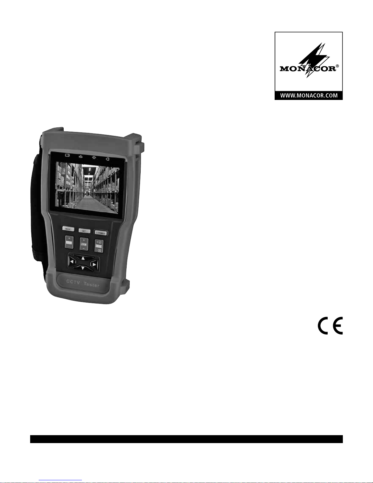
AHD-100TEST
Bestell-Nr. • Order No. 18.4350
Multifunktionstestgerät
für die Videoinstallation
Multifunction Tester
for Video Installation
Page 2
2
T
R
MODE
FOCUS
CCTV Tester
+
−
+
−
+
−
☑
☒
ZOOM IRIS
SET POWER
IN–VIDEO –OUT
RS485
UTP CABLE TEST
RESET
DC 12V/1 A
OUTPUT
INPUT
DC 5V
RS232
USB
AUDIO IN
+−
1 2 3
4 5 6 7
8
9
10
11
12
13
14
15
16
17
23
24
25
18
19
20
21
22
Page 3

3
ELECTRONICS FOR SPECIALISTS ELECTRONICS FOR SPECIALISTS ELECTRONICS FOR SPECIALISTS ELECTRONICS FOR SPECIALISTS
Deutsch .......... Seite 4
English ........... Page 14
Français .......... Page 24
Italiano........... Pagina 34
Page 4

4
Deutsch
Multifunktionstestgerät
Diese Anleitung richtet sich an Installateure von
Videoüberwachungsanlagen. Bitte lesen Sie die
Anleitung vor dem Betrieb gründlich durch und
heben Sie sie für ein späteres Nachlesen auf. Auf
Seite 2 finden Sie alle beschriebenen Bedienelemente und Anschlüsse.
Inhalt
1 Übersicht der Bedienelemente
und Anschlüsse
1
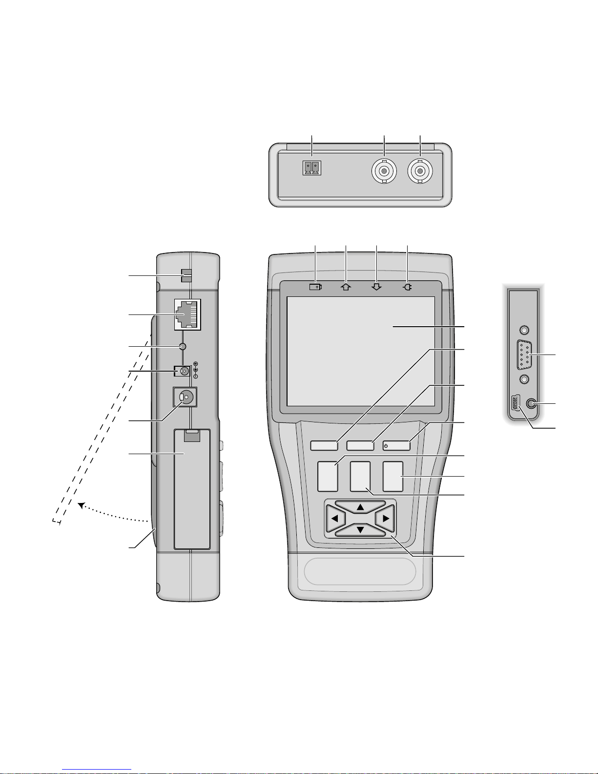
RS-485 /422-Kontakte zum Fernsteuern
einer Kamera und zum Empfang von Steuersignalen; Steckschraubklemmen für den
Anschluss liegen bei
2
Videosignalausgang VIDEO OUT als
BNC-Buchse zum Anschluss eines Monitors
3
Videosignaleingang VIDEO IN als BNC-Buchse zum Anschluss einer Kamera mit AHDoder FBAS-(Composite-)Videosignal.
4 Ladesymbol, leuchtet, wenn der Akku auf-
geladen wird
5 Anzeige für das Senden von Steuersignalen
6
Anzeige für den Empfang von Steuersignalen
7 Anzeige für den Betrieb mit dem Netzgerät
oder über die Mini-USB-Buchse (25)
8
Befestigungsstifte auf der linken und rechten
Seite für das beiliegende Nackenband
9
RJ45-Buchse UTP CABLE TEST zum Testen
eines Netzwerkkabels
An das andere Kabelende den beiliegenden
Testadapter stecken.
10 versenkter Taster RESET zum Zurücksetzen
des Testgeräts; Betätigung mit einem dünnen Gegenstand
11
Ausgang mit eine Gleichspannung von 12 V,
z. B. für die Behelfsversorgung einer zu testenden Kamera
12
Buchse zum Anschluss des beiliegenden
Netzgeräts für den Netzbetrieb und zum
Aufladen des internen Akkus
13 Batteriefachdeckel
14 herausklappbarer Aufstellbügel
15 LCD-Bildschirm
16
Taste MODE zum Aufruf des Bildschirmmenüs
1 Übersicht der Bedienelemente und
Anschlüsse � � � � � � � � � � � � � � � � � � 4
2 Hinweise fürdensicherenGebrauch � � � 5
3 Einsatzmöglichkeiten undZubehör � � � � 6
4 Inbetriebnahme � � � � � � � � � � � � � � � 6
4�1 Akkumulator anschließen � � � � � � � � � � � 6
4�2 Akkumulator aufladen � � � � � � � � � � � � �6
4�3 Band befestigen � � � � � � � � � � � � � � � � 7
5 Behelfsversorgung � � � � � � � � � � � � � 7
6 Bedienung � � � � � � � � � � � � � � � � � � 7
6�1 Grundeinstellungen � � � � � � � � � � � � � � 8
6�1�1 Datum und Uhrzeit � � � � � � � � � � � � 8
6�1�2 Automatische Abschaltung� � � � � � � � � 8
6�1�3 Tastenton � � � � � � � � � � � � � � � � � 8
6�1�4 Bildschirmhelligkeit � � � � � � � � � � � � 8
6�1�5 Menüsprache � � � � � � � � � � � � � � � 8
6�2 Videosignal prüfen � � � � � � � � � � � � � � �8
6�3 Tonsignal prüfen � � � � � � � � � � � � � � � �9
6�4 Testbild ausgeben � � � � � � � � � � � � � � �9
6�5 PTZ-Steuerung � � � � � � � � � � � � � � � � � 9
6�5�1 Konfigurieren der Schnittstelle � � � � � � 10
6�5�2 Adressensuche� � � � � � � � � � � � � � 10
6�6 Datenmonitor � � � � � � � � � � � � � � � � 11
6�7 Kabeltest� � � � � � � � � � � � � � � � � � � 12
7 Technische Daten � � � � � � � � � � � � � 13
Page 5
5
Deutsch
17 Taste SET zum Aufruf von Einstellungen
18 Ein-/Ausschalter POWER
(Taste länger drücken)
19
Taste FOCUS ± zum Fernsteuern der Bild
schärfe einer Kamera und zum Durchführen
einiger Einstellungen im Bildschirmmenü
20 Taste IRIS + ☑ / − ☒ zum Fernsteuern der
Blende einer Kamera und zum Durchführen
einiger Einstellungen im Bildschirmmenü
21 Taste ZOOM ± zum Fernsteuern der Brenn-
weite einer Kamera und zum Durchführen
einiger Einstellungen im Bildschirmmenü
22
Richtungstasten , , , zum Fernsteu-
ern der Bewegung einer Kamera und zur
Bedienung des Bildschirmmenüs
23
D-Sub-Buchse RS232 zum Fernsteuern einer
Kamera und zum Empfang von Steuersignalen
24
Audioeingang AUDIOIN als 3,5-mm-Klinkenbuchse zum Testen eines Audiosignals
über den internen Lautsprecher
25
Mini-USB-Buchse zum Laden des internen
Akkus über den USB-Anschluss z. B. eines
Computers
2 Hinweise
fürdensicherenGebrauch
Die Geräte (Testgerät und Netzgerät) entsprechen allen relevanten Richtlinien der EU und
sind deshalb mit ge kennzeichnet.
WARNUNG
Das Netzgerät wird mit lebensgefähr licher Netzspannung
versorgt. Nehmen Sie deshalb
nie selbst Eingriffe daran vor.
Durch unsachgemäßes Vorgehen besteht die Gefahr eines
elektrischen Schlages.
•
Verwenden Sie das Testgerät nur in einer
Umgebung mit folgenden Bedingungen:
Umgebungstemperatur: −20 bis +70 °C
Relative Luftfeuchtigkeit: 30 bis 90 %
Achten Sie immer darauf, dass keine Feuchtigkeit in das Gerät gelangt.
•
Verwenden Sie das Netzgerät nur im Innenbereich. Schützen Sie es vor Tropf- und
Spritzwasser sowie vor hoher Luftfeuchtigkeit.
Der zulässige Einsatztemperaturbereich für
das Netzgerät beträgt 0 – 40 °C.
•
Verwenden Sie zum Reinigen nur ein trockenes, weiches Tuch, niemals Wasser oder
Chemikalien.
•
Werden die Geräte zweckentfremdet, nicht
richtig angeschlossen, falsch bedient oder
nicht fachgerecht repariert, kann keine Haftung für daraus resultierende Sach- oder
Personenschäden und keine Garantie für die
Geräte übernommen werden.
Sollen die Geräte endgültig aus dem
Betrieb genommen werden, übergeben
Sie sie zur umweltgerechten Entsorgung
einem ört lichen Recyclingbetrieb.
Page 6

6
Deutsch
3 Einsatzmöglichkeiten
undZubehör
Das AHD-100TEST ist ein vielseitiges Werkzeug
für die Installation von Videoüberwachungsanlagen. Es bietet folgende Funktionen:
–
Überprüfung von AHD- und FBAS-(Composite-)Videosignalen auf dem 8,6-cm-Bildschirm mit Analyse der Signalart und Messung
des Signalpegels
– Überprüfung von Tonsignalen über den ein-
gebauten Lautsprecher
–
Signalgenerator für ein Farbbalkentestbild
nach verschiedenen Signalstandards
–
Fernsteuerung von Kameras (Schwenken, Nei
gen, Zoom, Fokus, Iris) über RS-485, RS-422
oder RS-232; 33 Steuerprotokolle wählbar
– Analyse von empfangenen Steuerdaten über
RS-485, RS-422 oder RS-232
–
Leistungsstarker interner Li-Polymer-Akku für
den netzunabhängigen Betrieb
–
Gleichspannungsausgang 12 V/1 A z. B. als
Behelfsversorgung für Kameras
–
Testfunktion für Netzwerkkabel mit RJ45-Steckern
Zum Lieferumfang gehört folgendes Zubehör:
– Netzgerät
– Tragetasche für Testgerät und Zubehör
– Gummi-Schutzrahmen, Nackenband
– Kabel zur Kamerastromversorgung
–
Audiokabel mit 3,5-mm-Klinkenstecker auf
Krokodilklemmen
– BNC-Videokabel
– RS-485/422-Kabel mit Krokodilklemmen
–
Steckschraubklemmen für RS-485/422-An
schluss
– RJ45-Testadapter für Netzwerkkabel
– Bedienungsanleitung
4 Inbetriebnahme
4.1 Akkumulator anschließen
Der interne Lithium-Polymer-Akku hat eine
große Energiedichte und kann sich bei Kurzschluss, z. B. durch mechanische Beschädigung,
überhitzen. Aus Sicherheitsgründen beim Transport ist der Akku daher bei Auslieferung noch
nicht an das Testgerät angeschlossen. Im normalen Betrieb geht jedoch keine Gefahr von dem
Akku aus. Zum Anschließen des Akkus:
1) Den Gummi-Schutzrahmen entfernen.
2) Den Batteriefachdeckel (13) öffnen.
3) Den Stecker des Akkus mit der Buchse auf
der Leiterplatte (links) verbinden. Ein Piepton
bestätigt die Verbindung.
4) Das Batteriefach wieder schließen und den
Gummirahmen wieder anlegen.
Das Testgerät ist jetzt betriebsbereit. Es können erste Grundeinstellungen, wie z. B. Datum
und Uhrzeit vorgenommen werden (☞Kapitel
6.1.1).
4.2 Akkumulator aufladen
Zum Aufladen des eingebauten Akkus das mitgelieferte Netzgerät an die Buchse INPUT DC5 V
(12) und an eine Netzsteckdose (230 V / 50 Hz)
anschließen oder die Mini-USB-Buchse (25)
mit dem USB-Anschluss z. B. eines Computers
oder Netzgerätes verbinden. Das Symbol
(4) leuchtet und der Akku wird geladen. Das
Testgerät kann dabei ausgeschaltet sein.
Der Ladevorgang dauert bei entladenem
Akku über das beiliegende Netzgerät ca. 4 h,
über den USB-Anschluss ca. 8 h. Wenn der Akku
aufgeladen ist, erlischt das Symbol; das Netzgerät dann vom Testgerät und vom Netz trennen
bzw. den USB-Anschluss trennen.
Page 7
7
Deutsch
Wichtig: Der Akku erfordert eine spezielle
Ladeelektronik; laden Sie ihn deshalb nur in
Verbindung mit dem Testgerät auf.
Defekte Akkus dürfen nicht in den
Hausmüll geworfen werden. Geben Sie
sie zur umweltgerechten Entsorgung
nur in den Sondermüll (z. B. Sammelbehälter bei Ihrem Fachhändler).
4.3 Band befestigen
Zum Lieferumfang gehört ein Band, mit dem
das Testgerät um den Nacken getragen werden
kann. Zum Befestigen des Bandes:
1) Den Gummi-Schutzrahmen entfernen.
2)
Auf der Gehäuseunterseite befindet sich links
und rechts unterhalb der Befestigungsstifte (8) jeweils eine Schraube. Die Schrauben
lösen, bis sich die obere und untere Gehäuseschale vorsichtig so weit auseinanderziehen
lassen, dass die dünnen Schlaufen des Bandes um die Befestigungsstifte gelegt werden
können.
3) Die Schrauben wieder festziehen, sodass die
Schlaufen des Bandes nicht mehr herausrutschen können.
4)
Bei Bedarf den Gummi-Schutzrahmen wieder
auf das Testgerät setzen.
5 Behelfsversorgung
Das Testgerät verfügt über einen Gleichspannungsausgang (11) von 12 V mit einer Belastbarkeit von max. 1 A. Hierüber kann z. B. eine Kamera für einen Testbetrieb versorgt werden oder
ein Signalkonverter (z. B. für TVI-Kamerasignale).
Für den Anschluss kann das beiliegende Adapterkabel verwendet werden. Es verfügt über den
bei Kameras üblichen Hohlstecker ⌀5,5 / 2,1 mm
(außen / innen); der Pluspol ist mit dem Innenkontakt verbunden.
6 Bedienung
1)
Zum Einschalten des Testgeräts die Taste
POWER (18) drücken, bis der Bildschirm (15)
leuchtet. Das Hauptmenü wird angezeigt:
PTZ Controller
Video Analyze
Colorbar Generator
Cable Tester
Data Monitor
Device Set
Diese Anleitung bezieht sich auf das englische Menü, die Menüsprache kann aber bei
Bedarf geändert werden (☞Kapitel 6.1.5).
Oben rechts neben dem Menü werden die
Uhrzeit und der Ladezustand des Akkus angezeigt:
Ist der Akku stark entladen (das Symbol
ist rot), sollte er wieder geladen werden
(☞Kapitel 4.2).
Bei Betrieb mit dem Netzgerät oder über die
Mini-USB-Buchse (25) leuchtet zusätzlich das
Symbol (7).
Hinweis: Ist der Akku entladen, steht beim Betrieb
über die Mini-USB-Buchse aufgrund der Strombegrenzung eines USB-Anschlusses am Gleichspannungsausgang (11) eine entsprechend geringere
Leistung zur Verfügung.
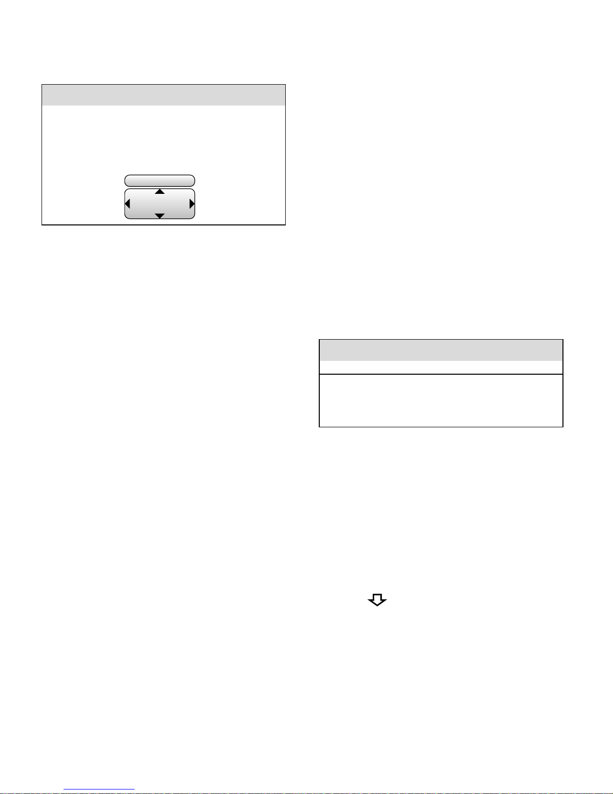
2) Mit der Taste oder (22) den gewünschten Menüpunkt wählen. Der gewählte Menüpunkt wird nach etwa 2 s aufgerufen.
Die einzelnen Menüpunkte werden in den
folgenden Kapiteln beschrieben.
3) Für die Rückkehr zum Hauptmenü die Taste
MODE (16) drücken.
4)
Bei Bedarf den Bügel (14) herausklappen, um
das Gerät aufzustellen.
5) Soll das Gerät auf seine Werkseinstellungen
zurückgesetzt werden, den Taster RESET (10)
mit einem dünnen Gegenstand betätigen.
6) Zum Ausschalten die Taste POWER drücken,
bis der Bildschirm erlischt.
Page 8

8
Deutsch
6.1 Grundeinstellungen
1) Den Menüpunkt Device Set aufrufen.
Das folgende Untermenü wird angezeigt:
Device Setting
Auto poweroff : 20 Minutes
Keypad tone : enable
Language : English
Backlight : 5
Address Search : Disable
System time : 14:48:03
System date : 2016/03/15
2) Mit der Taste oder (22) die gewünschte
Einstellung wählen. Die einzelnen Einstellungen werden im Folgenden beschrieben.
3)
Eine durchgeführte Änderung durch Drücken
von ☑ (20) bestätigen oder mit ☒ (20) verwerfen.
6.1.1 Datum und Uhrzeit
Zur Einstellung des Datums die Zeile System
date wählen. Das Datum wird im Format „Jahr/
Monat / Tag“ angezeigt. Zum Ändern des Jahres
die Taste FOCUS (19), für den Monat die Taste
ZOOM (21) und für den Tag die Tasten und
(22) verwenden.
Zur Einstellung der Uhrzeit die Zeile System
time wählen. Zum Ändern der Stunde die Taste
FOCUS (19), für die Minute die Taste ZOOM
(21) und für die Sekunde die Tasten und
(22) verwenden. Die Änderungen mit ☑ (20)
bestätigen.
6.1.2 Automatische Abschaltung
Über die Zeile
Auto poweroff kann eine Zeit vor-
gegeben werden, nach der sich das Testgerät
bei Nichtgebrauch automatisch abschaltet. Dies
verhindert eine unnötige Entladung des Akkus.
Mit den Tasten und (22) eine Änderung
vornehmen und mit ☑ (20) bestätigen. Bei der
Einstellung
Disable
ist die automatische Abschal-
tung deaktiviert.
6.1.3 Tastenton
Zum Deaktivieren des Piepens bei jedem Tastendruck:
1) Die Zeile Keypad tone wählen.
2)
Mit den Tasten und (22) die Option
Disable einstellen.
3) Die Änderung mit ☑ (20) bestätigen.
6.1.4 Bildschirmhelligkeit
Zum Ändern der Bildschirmhelligkeit die Zeile
Backlight wählen und mit den Tasten und
(22) die Helligkeit einstellen.
6.1.5 Menüsprache
Zum Ändern der Menüsprache:
1) Die Zeile Language wählen.
2)
Mit den Tasten und (22) die gewünschte
Sprache einstellen.
3) Die Änderung mit ☑ (20) bestätigen.
6.2 Videosignal prüfen
Zum Prüfen eines AHD- oder FBAS-(Composite-)
Videosignals (z. B. von einer Kamera):
1) Die Videoquelle über ein 75-Ω-Kabel an die
BNC-Buchse VIDEO IN (3) anschließen.
2) Den Menüpunkt Video Analyze aufrufen.
Das Videobild wird auf dem Bildschirm (15)
angezeigt. Darin eingeblendet wird der gemessene Signalpegel Amplitude sowie das
erkannte Signalformat [z. B. PAL (BDGHI)].
Ist keine Videoquelle angeschlossen, wird das
vom Testgerät generierte Testbild angezeigt.
3)
Das Videobild wird bildschirmfüllend angezeigt (Einblendung:
DigitalZoom : Fit
). Um
einen Bildausschnitt genauer zu betrachten,
mit der Taste ZOOM (21) den Vergrößerungsfaktor (
1× … 4×
) wählen und mit den
Richtungstasten (22) den gewünschten Bildausschnitt. Die Position des Ausschnitts inner-
Page 9

9
Deutsch
halb des Bildes wird in einem eingeblendeten
Rechteck als grünes Kästchen dargestellt.
4) Zum Ändern der Bildeinstellungen die Taste
SET (17) drücken. Folgende Einstellmöglichkeiten werden angezeigt:
Video analyze
Brightness : +30 Helligkeit
Contrast: 100% Kontrast
Saturation : 100% Farbsättigung
Mit der Taste oder (22) die gewünschte
Einstellung wählen und mit den Tasten
und (22) eine Änderung vornehmen. Abschließend erneut die Taste SET (17) drücken.
6.3 Tonsignal prüfen
Zum Prüfen eines Tonsignals z. B. den Audioausgang einer Kamera mit der 3,5-mm-Klinkenbuchse AUDIOIN (24) verbinden. Die Buchse ist
3-polig beschaltet und damit auch zum Testen
für Stereosignale geeignet. Der Ton wird über
den Lautsprecher in der Geräteunterseite
(monofon) ausgegeben.
6.4 Testbild ausgeben
Zur Prüfung eines Monitors oder Videorekorders
kann das Testgerät ein Testsignal mit einem Farbbalkentestbild ausgeben.
1) Den Videoeingang des zu testenden Geräts
über ein 75-Ω-Kabel mit der BNC-Buchse
VIDEOOUT (2) verbinden.
2)
Den Menüpunkt
Colorbar Generator
aufrufen.
3)
Mit der Taste oder (22) die Zeile
standard
wählen und mit den Tasten und (22) den
gewünschten Farbfernsehstandard einstellen.
4)
Mit der Taste oder die Zeile
display select
wählen und mit den Tasten und einstellen, ob das erzeugte Testbild (video Out-
put) oder das Signal am Videoeingang (video
Input) auf dem Bildschirm angezeigt wird.
Indem ein Testsignal über den Videoausgang
ausgegeben und das am Videoeingang anliegende Signal angezeigt wird, lässt sich die
Qualität einer dazwischen angeschlossenen
Übertragungsstrecke beurteilen.
6.5 PTZ-Steuerung
Zum Testen von Kameras mit Fernsteuermöglichkeiten für deren Bewegungen oder Linsen
(PTZ = pan, tilt, zoom):
1)
Eine Kamera mit RS-485- oder RS-422-Schnittstelle an die Buchsen RS485 (1) anschließen.
Dazu können die beiliegenden Steckschraubklemmen oder das Adapterkabel mit den
Krokodilklemmen verwendet werden. Beim
Anschluss auf die Polarität achten!
Alternativ kann für eine Steuerung über eine
RS-232-Schnittstelle die Buchse RS232 (23)
verwendet werden.
2) Den Menüpunkt PTZ Controller aufrufen.
3)
Die Schnittstelle entsprechend der angeschlossenen Kamera konfigurieren (☞Kapitel
6.5.1).
4)
Mit den Richtungstasten (22) die Kamera
schwenken ( und ) oder neigen ( und
).
5) Mit den Tasten ZOOM (21), FOCUS (19) und
IRIS (20) die Brennweite, Schärfe und Blende der Kamera verändern. Die Verfügbarkeit
dieser Funktionen hängt vom verwendeten
Kameramodell ab.
6)
Möglichkeiten zum Steuern der Bewegungsgeschwindigkeit der Kamera sowie
zum Laden und Speichern von Presets in der
Kamera sind über ein Untermenü zugänglich
(☞Kapitel 6.5.1).
Bei jedem gesendeten Steuerbefehl blinkt kurz
das Symbol
T
(5) auf.
Page 10

10
Deutsch
6.5.1 Konfigurieren der Schnittstelle
Soll eine Kamera zum ersten Mal mit dem Testgerät ferngesteuert werden, muss zunächst die
Schnittstelle entsprechend der verwendeten
Kamera konfiguriert werden.
1) Bei aufgerufenem Menüpunkt PTZ Controller
die Taste SET (17) drücken. Die folgenden
Einstellmöglichkeiten werden angezeigt.
PTZ Controller
protocol : pelco D Steuerprotokoll
port: RS485 Schnittstelle
baud : 2400 Datenrate
address : 1 Kamera-Adresse
pan speed : 40 Schwenkgeschwindigkeit
tilt speed : 40 Neigegeschwindigkeit
save preset : 8 Einstellung speichern
call preset : 8 Einstellung laden
2) Mit der Taste oder (22) die gewünschte
Einstellung wählen.
3)
Mit den Tasten und (22) eine gewünsch
-
te Änderung vornehmen.
4)
Die Einstellungen pan speed und tilt speed
sind keine Schnittstellenparameter, sondern
steuern die Bewegungsgeschwindigkeit der
Kamera.
5) Bei den Optionen save preset und call preset
handelt es sich um Positionen und Einstellungen der Kamera, die in der Kamera gespeichert werden. Vor der Nutzung dieser
Funktionen müssen die anderen Schnittstellenparameter korrekt eingestellt sein.
Die Anzahl der verfügbaren Speicherplätze
hängt vom verwendeten Kameramodell ab.
Nach der Wahl der Speicherplatznummer
den Speicher- bzw. Ladevorgang mit ☑ (20)
ausführen.
Bei einigen Kameramodellen können über
den Aufruf bestimmter Speicherplatznummern Sonderfunktionen ausgelöst werden (z. B. Aufruf des Bildschirmmenüs der
Kamera, ☞Anleitung der Kamera).
Um die unbekannte Adresse einer Kamera herauszufinden, kann die Funktion der Adressensuche verwendet werden (☞Kapitel 6.5.2).
6.5.2 Adressensuche
Nicht immer ist die Adresse einer Kamera innerhalb einer bestehenden Installation leicht
herauszufinden. Die Funktion „Adressensuche“
kann dabei helfen.
Wichtig: Diese Funktion darf nur mit einer einzelnen Kamera verwendet werden. Rufen Sie
die Funktion niemals auf, wenn das Testgerät
mit einem Datenbus verbunden ist, an dem
mehrere Kameras angeschlossen sind.
1) Den Menüpunkt Device Set aufrufen.
2)
Mit der Taste oder (22) die Zeile
Address
Search wählen.
3)
Mit den Tasten und (22) die Option
Enable einstellen.
4) Die Änderung mit ☑ (20) bestätigen.
5)
Mit der Taste MODE (16) zum Hauptmenü
zurückkehren.
6)
Den neu hinzugekommenen Menüpunkt
PTZ Address Search aufrufen. (In der Regel
geschieht dies automatisch, da dieser nach
Verlassen des Untermenüs bereits angewählt
ist.)
Hinweis: Gegen versehentliche Benutzung ist dieser Menüpunkt nach jedem neuen Einschalten des
Testgeräts wieder ausgeblendet.
Page 11
11
Deutsch
Folgende Einstellmöglichkeiten werden angezeigt:
PTZ Address Search
protocol : − Pelco D +
port : RS485
baud : 2400
address : − 1 +
± StartSearch
Try Control
– Das Steuerprotokoll protocol kann mit der
Taste FOCUS (19) geändert werden.
–
Die Adresse address kann mit der Taste
ZOOM (21) manuell gewählt werden.
–
Zum Starten und Stoppen des automatischen Adressdurchlaufs vorwärts (+) oder
rückwärts (−) die Taste IRIS (20) verwenden.
Wird während des Adressdurchlaufs die
Adresse der Kamera erreicht, reagiert die
Kamera mit Bewegung. In diesem Fall den
Adressdurchlauf stoppen, um die Richtigkeit der Adresse zu prüfen; ggf. die Adresse im aktuellen Bereich manuell variieren.
–
Zum Testen der Steuerbarkeit die Tasten
, , und
verwenden.
–
Zum Ändern der Einstellungen für
port
und
baud die Taste SET (17) drücken. Mit der
Taste oder die gewünschte Einstellung wählen und mit den Tasten und
eine Änderung vornehmen. Abschließend
erneut die Taste SET drücken.
6.6 Datenmonitor
Zur Überprüfung von Kamerasteuerbefehlen,
die z. B. von einem Steuerpult oder Videorekorder gesendet werden:
1)
Die Leitung für eine Steuerung über eine RS485- oder RS-422-Schnittstelle an die Buchsen RS485 (1
) anschließen. Dazu können die
beiliegenden Steckschraubklemmen oder das
Adapterkabel mit den Krokodilklemmen verwendet werden. Beim Anschluss auf die Polarität achten!
Alternativ kann für eine Steuerung über eine
RS-232-Schnittstelle die Buchse RS232 (23)
verwendet werden.
2) Den Menüpunkt Data Monitor aufrufen. Folgendes Bild wird angezeigt.
Data Monitor
port : RS485 baud : 2400
3) Zum Anpassen der Einstellungen für die verwendete Schnittstelle
port
und die Datenrate
baud
die Taste SET (17) drücken. Mit der Taste
oder (22) die gewünschte Einstellung
wählen und mit den Tasten und eine
Änderung vornehmen. Abschließend erneut
die Taste SET drücken.
4) Am Steuergerät ein Steuerkommando senden. Beim Empfang von Daten leuchtet das
Symbol
R
(6). Die empfangenen Daten
werden auf dem Bildschirm als hexadezimale
Zahlenreihe angezeigt.
5)
Ist die unterste Bildschirmzeile erreicht, scrollt
der Bildschirminhalt beim Empfang weiterer
Daten nach oben.
Zum Löschen des Bildschirminhalts ☑ oder
☒ (20) drücken.
Page 12
12
Deutsch
6.7 Kabeltest
Zum Prüfen eines Netzwerkkabels oder Telefonkabels mit RJ45-Steckern:
1)
Ein Kabelende mit der Buchse UTP CABLE
TEST (9) verbinden.
2) Auf den Stecker am anderen Kabelende den
beiliegenden Testadapter „Cable Tester“ stecken.
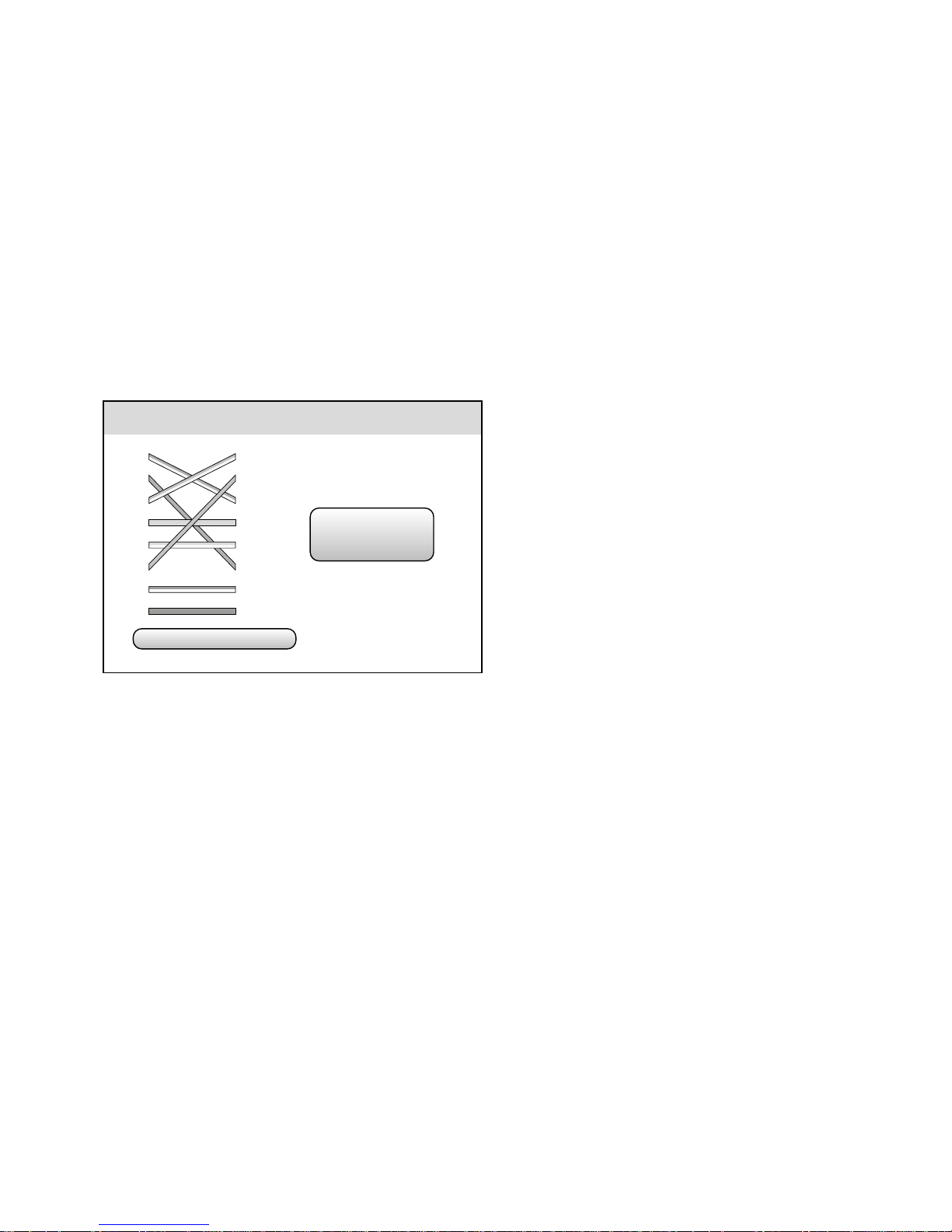
3)
Den Menüpunkt Cable Tester aufrufen. Es
wird beispielsweise folgendes Bild angezeigt.
Cable tester
type: Cross Eth.
Remote No.
255
1
2
3
4
5
6
7
8
1
2
3
4
5
6
7
8
Die Verbindungen zwischen den 8 Steckerkontakten werden als Linien in den Farben
der üblichen Kabeladern angezeigt. Gängige Kabeltypen werden erkannt und unten
als type: angezeigt (bei diesem Beispiel:
Cross-Ethernet-Kabel). Die Nummer des verwendeten Testadapters wird als
RemoteNo.
ebenfalls angezeigt.
Ist ein Steckerkontakt nicht verbunden, steht
bei der Zahl ein X.
Page 13

13
Deutsch
7 Technische Daten
LCD-Bildschirmdiagonale: �8,6 cm (3,5”)
Videoeingang: � � � � � � � � � � 1 V, AHD- oder
FBAS-(Composite-)Signal,
PAL oder NTSC
Generator mit Farbbalkentestbild
Signalstandards: � � � � � �PAL-B, D, G, H, I
PAL-M
PAL-N (Arg�)
PAL-N (non Arg�)
NTSC-M (CCIR601)
NTSC-M (JAPAN)
NTSC-M (RS170A)
PTZ-Steuerung
Schnittstellen: � � � � � � � � �RS-485, RS-422, RS-232
Datenraten: � � � � � � � � � � 150 … 19 200 Bd
Steuerprotokolle: � � � � � �AD168 (M-B)
ADmanchest
ALEC
BOSCHOSRD
CBC
DAT-SD
DH-YTCO6
Fastrax
HD600
Hikvision
Kalatel304
KalatelASC
LC-NEW
LG-MULTIX
Lilin-FAST
Lilin-MLP2
MinkingAO1
MinkingBO1
Molynx
Panasonic
PEARMAIN
Pelco D
Pelco P
Samsung
Santachi
SANYO-SSP
SONY-EVI
TeleEye DM2
Vicon
Vcltp
WV-CS850
YAAN
YAAN-O
Stromversorgung:
� � � � � � �Lithium-Polymer-Akku
3,7 V/ 3 Ah
oder über beiliegendes
Netzgerät an 230 V/ 50 Hz
Alternativer Ladeanschluss: Mini-USB
Gleichspannungsausgang:
�12 V/1 A
Abmessungen:� � � � � � � � � �112 × 188 × 45 mm
Gewicht: � � � � � � � � � � � � � � 435 g
Änderungen vorbehalten.
Diese Bedienungsanleitung ist urheberrechtlich für MONACOR ® INTERNATIONAL GmbH & Co. KG geschützt.
Eine Reproduktion für eigene kommerzielle Zwecke – auch auszugsweise – ist untersagt.
Page 14

14
English
Multifunction Tester
These instructions are intended for installers
of video surveillance systems. Please read the
instructions carefully prior to operation and
keep them for later reference. All operating
elements and connections described can be
found on page 2.
Contents
1 Operating Elements
andConnections
1
RS-485 /422 contacts for remote control of a
camera and for reception of control signals;
plug-in screw terminals for connection are
provided
2 Video signal output VIDEO OUT (BNC jack)
for connecting a monitor
3 Video signal input VIDEO IN (BNC jack) for
connecting a camera with AHD or composite
video signal
4
Charge indicator; lights up when the battery
is being charged
5 Transmission indicator for control signals
6 Reception indicator for control signals
7
Power indicator for operation via power supply unit or via mini USB port (25)
8 Pins on the left and on the right to attach
the neck strap provided
9
RJ45 jack UTP CABLE TEST for testing a net
-
work cable
Connect the test adapter provided to the
other end of the cable.
10 Pushbutton RESET; to reset the tester, use a
thin object to press the recessed pushbutton
11
Output with 12 V direct voltage, e. g. for
temporary power supply of a camera to be
tested
12 Jack to connect the power supply unit pro-
vided for mains operation and for charging
the internal battery
13 Battery compartment cover
14 Tilt stand
15 LCD screen
16 Button MODE to call up the OSD menu
17 Button SET to call up settings
1 Operating Elements andConnections � � 14
2 Safety Notes � � � � � � � � � � � � � � � � 15
3 Applications and Accessories � � � � � � 16
4 Operation � � � � � � � � � � � � � � � � � 16
4�1 Connecting the battery� � � � � � � � � � � � 16
4�2 Charging the battery � � � � � � � � � � � � � 16
4�3 Attaching the neck strap � � � � � � � � � � � 17
5 Temporary Power Supply � � � � � � � � � 17
6 Operation � � � � � � � � � � � � � � � � � 17
6�1 Basis settings � � � � � � � � � � � � � � � � 18
6�1�1 Date and time � � � � � � � � � � � � � � 18
6�1�2 Automatic switch-off� � � � � � � � � � � 18
6�1�3 Keypad tone � � � � � � � � � � � � � � � 18
6�1�4 Backlight brightness � � � � � � � � � � � 18
6�1�5 Menu language � � � � � � � � � � � � � 18
6�2 Testing a video signal � � � � � � � � � � � � 18
6�3 Testing an audio signal � � � � � � � � � � � � 19
6�4 Generating a test pattern� � � � � � � � � � � 19
6�5 PTZ control� � � � � � � � � � � � � � � � � � 19
6�5�1 Configuring the interface � � � � � � � � 20
6�5�2 Address search � � � � � � � � � � � � � 20
6�6 Data monitor� � � � � � � � � � � � � � � � � 21
6�7 Cable test � � � � � � � � � � � � � � � � � � 21
7 Specifications � � � � � � � � � � � � � � � 22
Page 15

15
English
18 POWER button (keep pressed for a while)
19 Button FOCUS ± for remote control of the
focus of a camera and for making specific
settings in the OSD menu
20 Button IRIS + ☑ / − ☒ for remote control of
the iris of a camera and for making specific
settings in the OSD menu
21 Button ZOOM ± for remote control of the
focal length of a camera and for making
specific settings in the OSD menu
22
Arrow buttons , , , for remote
control of the camera movement and for
controlling the OSD menu
23
D-Sub jack RS232 for remote control of a
camera and for receiving control signals
24
Audio input AUDIO IN (3.5 mm jack) for testing an audio signal via the internal speaker
25 Mini USB port for charging the internal bat-
tery via the USB connection of a computer,
for example
2 Safety Notes
The units (tester and power supply unit) correspond to all relevant directives of the EU and are
therefore marked with .
WARNING
The power supply unit uses
dangerous mains voltage. Leave
servicing to skilled personnel.
Inexpert handling may result in
electric shock.
•
Only use the tester in an environment with
the following conditions:
Ambient temperature: –20 to +70 °C
Relative air humidity: 30 to 90 %
Always make sure that no moisture will get
inside the tester.
•
The power supply unit is suitable for indoor
use only. Protect it against dripping water,
splash water and high air humidity. The admissible ambient temperature range for the
power supply unit is 0 – 40 °C.
•
For cleaning only use a dry, soft cloth; never
use water or chemicals.
•
No guarantee claims for the units and no liability for any resulting personal damage or
material damage will be accepted if the units
are used for other purposes than originally
intended, if they are not correctly connected
or operated, or if they are not repaired in an
expert way.
If the units are to be put out of operation definitively, take them to a local
recycling plant for a disposal which is
not harmful to the environment.
Page 16

16
English
3 Applications and Accessories
The AHD-100TEST is a versatile tool for installation of video surveillance systems. It offers the
following features:
– testing of AHD and composite video signals
on the 8.6 cm (3.5 ”) screen including signal
type analysis and signal level measurement
–
testing of audio signals via integrated speaker
–
signal generator for a colour bar pattern in
accordance with various signal standards
–
remote control of cameras (pan, tilt, zoom,
focus, iris) via RS-485, RS-422 or RS-232;
33control protocols available
– analysis of control data received via RS-485,
RS-422 or RS-232
– powerful internal lithium polymer battery for
mains-independent operation
– direct voltage output 12 V/1 A, e. g. as a tem-
porary power supply for cameras
–
test function for network cables with RJ45
plugs
The following accessories are supplied with the
tester:
– power supply unit
– transport bag for tester and accessories
– protective rubber holster, neck strap
– cable for power supply of a camera
–
audio cable with 3.5 mm plug to crocodile
clips
– BNC video cable
– RS-485/422 cable with crocodile clips
– plug-in screw terminals for RS-485/422 con-
nection
– RJ45 test adapter for network cables
– instruction manual
4 Operation
4.1 Connecting the battery
The energy density of the internal lithium polymer battery is high and the battery may overheat
in case of short circuit (e. g. caused by mechanical damage). For reasons of safety during transport, the battery is not yet connected to the
tester in the factory. In normal use, however, the
battery is not dangerous. To connect the battery:
1) Remove the rubber holster.
2) Open the battery compartment cover (13).
3) Connect the plug of the battery to the jack
on the PCB (left side). A beep will confirm
successful connection.
4) Close the battery compartment and replace
the rubber holster.
The tester is now ready for operation. The first
basic settings (e.g. date and time) can be made
(☞chapter 6.1 .1).
4.2 Charging the battery
To charge the internal battery, connect the
power supply unit provided to the jack INPUT
DC 5V (12) and to a mains socket (230 V/50 Hz)
or connect the mini USB port (25) to the USB
connection of a computer or a power supply
unit, for example. The charge indicator (4)
will light up while the battery is charged. During
this process, the tester may be switched off.
When the battery is discharged, the charging time will be approx. 4 hours via the power
supply unit provided or approx. 8 hours via USB
connection. When the battery has been fully
charged, the charge indicator will go out; disconnect the power supply unit from the tester
and from the mains or disconnect the mini USB
plug.
Page 17

17
English
Important: The battery requires specific charge
electronics; therefore, only charge the battery
in combination with the tester.
Never put defective rechargeable
batteries in the household waste. To
protect the environment, always take
them to a special waste disposal, e. g.
collection container at your retailer.
4.3 Attaching the neck strap
A neck strap which can be used to wear the
tester around your neck is supplied with the
tester. To attach the strap:
1) Remove the rubber holster.
2)
On the rear of the tester, there is a screw
on the left and on the right at the level of
the pins (8). Release both screws and carefully pull apart the front and rear parts of the
housing. Then attach the thin loops of the
strap to the pins.
3) Fasten the screws to secure the loops of the
strap.
4) Replace the rubber holster, if required.
5 Temporary Power Supply
The tester is equipped with a 12 V direct voltage
output (11) with a current rating of 1 A max.
This output can be used, for example, for power
supply of a camera in test mode or for power
supply of a signal converter (e. g. for TVI camera
signals). For connection, use the adapter cable
provided. The cable is equipped with a common
DC power plug ⌀ 5.5/2.1 mm (outside / inside)
for cameras; the positive pole is connected to
the internal contact.
6 Operation
1)
To switch on the tester, press the button
POWER (18) until the screen (15) lights up.
The main menu is displayed:
PTZ Controller
Video Analyze
Colorbar Generator
Cable Tester
Data Monitor
Device Set
These instructions refer to the English
menu; however, the menu language can be
changed, if required (☞chapter 6.1.5).
In the top right corner next to the menu, the
time and the battery status are displayed.
If the battery is almost discharged (charge indicator is red), recharge it (☞chapter 4.2).
When the tester is operated via the power
supply unit or via the mini USB port (25), the
power indicator (7) lights up additionally.
Note: When the battery is discharged and the tester
is operated via the mini USB port, the power available at the direct voltage output (11) will be lower
due to current limiting for USB ports.
2)
Use the button or (22) to select the
desired menu item. The menu item selected
will be called up after approx. 2seconds.
The individual menu items are described in
the chapters below.
3)
To return to the main menu, press the button
MODE (16).
4) If required, use the tilt stand (14) to set up
the tester.
5)
To reset the tester to its factory settings, use a
thin object to press the recessed pushbutton
RESET (10).
6) To switch off, press the button POWER until
the screen goes dark.
Page 18

18
English
6.1 Basis settings
1) Call up the menu item Device Set.
The following submenu appears:
Device Setting
Auto poweroff : 20 Minutes
Keypad tone : enable
Language : English
Backlight : 5
Address Search : Disable
System time : 14:48:03
System date : 2016/03/15
2)
Use the button or (22) to select the
desired setting. The individual settings are
described below.
3) Press ☑ (20) to confirm the setting or ☒ (20)
to cancel the setting.
6.1.1 Date and time
To set the date, select the line
System date. The
date format is “year/month / day”. To change the
year, use the button FOCUS (19); to change the
month, use the button ZOOM (21); to change
the day, use the buttons and (22).
To set the time, select the line
System time
. To
change the hour, use the button FOCUS (19); to
change the minute, use the button ZOOM (21);
to change the second, use the buttons and
(22). Press ☑ (20) to confirm.
6.1.2 Automatic switch-off
In the line
Auto poweroff
, define a time after that
the tester will switch off automatically when it
is not used. This will save the battery.
Use the buttons and (22) to change the
time and press ☑ (20) to confirm. In the setting
Disable
, the automatic switch-off is deactivated.
6.1.3 Keypad tone
To deactivate the beep that sounds whenever a
button is pressed:
1) Select the line Keypad tone.
2)
Use the buttons and (22) to set the
option Disable.
3) Press ☑ (20) to confirm.
6.1.4 Backlight brightness
To change the backlight brightness, select the
line
Backlight
and use the buttons and (22)
to set the brightness level.
6.1.5 Menu language
To change the menu language:
1) Select the line Language.
2) Use the buttons and (22) to select the
desired language.
3) Press ☑ (20) to confirm.
6.2 Testing a video signal
To test an AHD or composite video signal (e. g.
from a camera):
1)
Use a 75 Ω cable to connect the video source
to the BNC jack VIDEO IN (3).
2) Call up the menu item Video Analyze.
The video image appears on the screen (15).
The signal level measured Amplitude and the
signal format recognized [e. g. PAL (BDGHI)]
are inserted in this image.
If no video source has been connected, the
test pattern generated by the tester will
appear.
3)
The video image is displayed in full-screen
mode (insertion DigitalZoom : Fit). To view
an image section in detail, use the button
ZOOM (21) to select the magnification factor
Page 19

19
English
(1× … 4×) and use the arrow buttons (22) to
select the desired image section. The position
of this section within the image is shown as
a green box in a rectangle.
4) To change the image settings, press the button SET (17). The following setting options
are displayed:
Video analyze
Brightness : +30
Contrast: 100%
Saturation : 100%
Use the button or (22) to select the
desired setting and use the buttons and
(22) to change the setting. Press the button
SET (17) again to confirm.
6.3 Testing an audio signal
To test an audio signal, connect, for example,
the audio output of a camera to the 3.5 mm
jack AUDIO IN (24). The jack has 3 poles and is
therefore also suitable for testing stereo signals.
The (monophonic) sound will come out of the
speaker on the rear of the tester.
6.4 Generating a test pattern
The tester is able to generate a test signal with
a colour bar pattern to test a monitor or video
recorder.
1) Use a 75 Ω cable to connect the video input
of the unit to be tested to the BNC jack
VIDEO OUT (2).
2) Call up the menu item Colorbar Generator.
3) Use the button or (22) to select the line
standard and use the buttons and (22)
to set the desired colour TV standard.
4)
Use the button or to select the line
display select and use the buttons and
to define whether the generated test pattern
(
video Output
) or the signal at the video input
(video Input) is displayed.
When a test signal is sent to the video output
and the signal available at the video input
is indicated, it will be possible to evaluate
the quality of a transmission path connected
between the output and the input.
6.5 PTZ control
To test cameras with remote control options
for their movements or lenses (PTZ = pan, tilt,
zoom):
1)
Connect a camera with RS-485 or RS-422
interface to the jacks RS485 (1). Use the plugin screw terminals or the adapter cable with
crocodile clips. Always observe the polarity
when connecting!
Alternatively, use the jack RS232 (23) for
control via RS-232 interface.
2) Call up the menu item PTZ Controller.
3) Configure the interface in accordance with
the camera connected (☞chapter 6.5.1).
4)
Use the arrow buttons (22) for pan ( and )
or tilt ( and ).
5)
Use the buttons ZOOM (21), FOCUS (19) and
IRIS (20) to adjust the focal length, focus and
iris of the camera. Depending on the camera model used, not every function may be
available.
6) Options to control the movement speed of
the camera and to load and save presets
in the camera are accessed via a submenu
(☞chapter 6.5.1).
The transmission indicator
T
(5) will briefly
flash whenever a control command is sent.
Page 20

20
English
6.5.1 Configuring the interface
Before a camera is remote-controlled with the
tester for the first time, configure the interface
in accordance with the camera used.
1)
When the menu item
PTZ Controller
has been
called up, press the button SET (17). The following setting options are displayed:
PTZ Controller
protocol : pelco D
port: RS485
baud : 2400
address : 1
pan speed : 40
tilt speed : 40
save preset : 8
call preset : 8
2)
Use the button or (22) to select the
desired setting.
3)
Use the buttons and (22) to change
the setting.
4) The settings pan speed and tilt speed are not
interface parameters; they are used to control
the movement speed of the camera.
5)
The options save preset and call preset are
positions and settings of the camera which
are stored in the camera. Before using these
functions, correctly adjust the other interface
parameters. The number of storage locations
available depends on the camera model used.
After selecting the storage location number,
press ☑ (20) to start the storage process or
loading process.
For certain camera models, special functions
can be activated (e. g. calling up the OSD
menu of the camera, ☞instructions of the
camera) when specific storage location numbers are called up.
To find out the address of a camera, an
address search function is available (☞chapter 6.5.2).
6.5.2 Address search
It is not always easy to find out the address
of a camera within an existing installation. The
„address search“ function may be useful.
Important: Only use this function for a single
camera. Never call up this function while the
tester is connected to a data bus to which
multiple cameras have been connected.
1) Call up the menu item Device Set.
2) Use the button or (22) to select the line
Address Search.
3) Use the buttons and (22) to select the
option Enable.
4) Press ☑ (20) to confirm.
5) Press the button MODE (16) to return to the
main menu.
6)
Call up the new menu item PTZ Address
Search. (Usually this menu item is auto-
matically selected after the submenu has
been exited.)
Note: To prevent accidental use, this menu item will
not appear when the tester is switched on.
The following setting options are displayed:
PTZ Address Search
protocol : − Pelco D +
port : RS485
baud : 2400
address : − 1 +
± StartSearch
Try Control
–
To change the control protocol
protocol
,
use the button FOCUS (19).
–
To manually select the address
address
, use
the button ZOOM (21).
–
To start and stop the automatic address
scan in forward (+) or backward (−) direction, use the button IRIS (20). If the camera
Page 21

21
English
address is found during the scan, the camera will start to move in response. In this
case, stop scanning to check if the address
is correct; if necessary, modify the address
manually in the current range.
–
To test if the camera can be controlled, use
the buttons , , and .
– To change the settings for port and baud,
press the button SET (17). Use the button or to select the desired setting
and use the buttons and to change
the setting. Press the button SET again to
confirm.
6.6 Data monitor
To test camera control commands which are
sent, for example, from a control panel or video
recorder:
1) Connect the cable for control via RS-485 or
RS-422 interface to the jacks RS485 (1). Use
the plug-in screw terminals provided or the
adapter cable with crocodile clips. Always
observe the polarity when connecting!
Alternatively, use the jack RS232 (23) for
control via RS-232 interface.
2) Call up the menu item Data Monitor. The following figure is displayed:
Data Monitor
port : RS485 baud : 2400
3) To adjust the settings for the interface port
and the data rate baud used, press the button SET (17). Use the button or (22) to
select the desired setting and use the buttons
and
to change the setting. Press the
button SET again to confirm.
4)
Send a control command from the controller.
When data is received, the reception indi-
cator
R
(6) lights up. The data received
is displayed on the screen as a hexadecimal
sequence of numbers.
5)
When the last line at the bottom of the screen
has been reached and additional data is received, the screen content will scroll upward.
To clear the screen, press ☑ or ☒ (20).
6.7 Cable test
To test a network cable or telephone cable with
RJ45 plugs:
1)
Connect one cable end to the jack UTP
CABLE TEST (9).
2)
Connect the test adapter „Cable Tester“
provided to the plug at the other cable end.
3)
Call up the menu item Cable Tester. As an
example, the following figure may appear:
Cable tester
type: Cross Eth.
Remote No.
255
1
2
3
4
5
6
7
8
1
2
3
4
5
6
7
8
The connections between the 8 plug contacts
are indicated as lines in the standard colours
of cable cores. Common cable types are
recognized and indicated at the bottom as
type: (in this example: Cross Ethernet cable).
The number of the test adapter used is also
indicated as RemoteNo.
The number of a plug contact not connected
is marked with an X.
Page 22

22
English
7 Specifications
Diagonal LCD screen size: � 8�6 cm (3�5”)
Video input: � � � � � � � � � � �1 V, AHD or composite
signal, PAL or NTSC
Generator with colour bar pattern
Signal standards: � � � � � � PAL-B, D, G, H, I
PAL-M
PAL-N (Arg�)
PAL-N (non Arg�)
NTSC-M (CCIR601)
NTSC-M (JAPAN)
NTSC-M (RS170A)
PTZ control
Interfaces:� � � � � � � � � � � �RS-485, RS-422, RS-232
Data rates: � � � � � � � � � � �150 … 19 200 Bd
Control protocols: � � � � � � AD168 (M-B)
ADmanchest
ALEC
BOSCHOSRD
CBC
DAT-SD
DH-YTCO6
Fastrax
HD600
Hikvision
Kalatel304
KalatelASC
LC-NEW
LG-MULTIX
Lilin-FAST
Lilin-MLP2
MinkingAO1
MinkingBO1
Molynx
Panasonic
PEARMAIN
Pelco D
Pelco P
Samsung
Santachi
SANYO-SSP
SONY-EVI
TeleEye DM2
Vicon
Vcltp
WV-CS850
YAAN
YAAN-O
Power supply:
� � � � � � � � � �rech� lithium polymer
battery
3�7 V/ 3 Ah
or via power supply unit
provided and connected
to 230 V/ 50 Hz
Alternative charging
connection:
� � � � � � � � � � � � mini USB
Direct voltage output:
� � � �12 V/1 A
Dimensions: � � � � � � � � � � � 112 × 188 × 45 mm
Weight: � � � � � � � � � � � � � � �435 g
Subject to technical modification.
All rights reserved by MONACOR ® INTERNATIONAL GmbH & Co. KG. No part of this instruction manual may
be reproduced in any form or by any means for any commercial use.
Page 23

23
English
Page 24

24
Français
Testeur multifonctions pour
installation vidéo
Cette notice s’adresse aux installateurs d‘installations de vidéo surveillance. Veuillez lire la
présente notice d‘utilisation avec attention avant
le fonctionnement et conservez-la pour pouvoir,
si besoin, vous y reporter ultérieurement. Vous
trouverez sur la page 2, les éléments et branchements décrits.
Table des matières
1 Eléments et branchements � � � � � � � � 24
2 Conseils d‘utilisation etdesécurité � � � 25
3 Possibilités d‘utilisation etaccessoires � 26
4 Fonctionnement � � � � � � � � � � � � � � 26
4�1 Branchement de l‘accumulateur � � � � � � � 26
4�2 Charge de l‘accumulateur � � � � � � � � � � 26
4�3 Fixation du tour de cou� � � � � � � � � � � � 27
5 Alimentation temporaire � � � � � � � � � 27
6 Utilisation � � � � � � � � � � � � � � � � � 27
6�1 Réglages de base � � � � � � � � � � � � � � 28
6�1�1 Date et heure � � � � � � � � � � � � � � 28
6�1�2 Déconnexion automatique � � � � � � � � 28
6�1�3 Son des touches � � � � � � � � � � � � � 28
6�1�4 Luminosité écran� � � � � � � � � � � � � 28
6�1�5 Langue du menu� � � � � � � � � � � � � 28
6�2 Vérifier un signal vidéo� � � � � � � � � � � � 28
6�3 Vérifier un signal audio� � � � � � � � � � � � 29
6�4 Générer une image test � � � � � � � � � � � 29
6�5 Gestion PTZ � � � � � � � � � � � � � � � � � 29
6�5�1 Configuration de l‘interface � � � � � � � 30
6�5�2 Recherche d‘adresse � � � � � � � � � � � 30
6�6 Moniteur de données � � � � � � � � � � � � 31
6�7 Test de câble � � � � � � � � � � � � � � � � � 32
7 Caractéristiques techniques � � � � � � � 33
1 Eléments et branchements
1
Contacts RS-485/422 pour une gestion à
distance d‘une caméra et pour recevoir les
signaux de commande ; bornes à pinces
pour le branchement sont livrées
2 Sortie signal vidéo VIDEO OUT (prise BNC)
pour brancher un moniteur
3
Entrée signal vidéo VIDEO IN (prise BNC)
pour brancher une caméra avec signal vidéo
AHD ou composite
4
Symbole de charge : brille lorsque l‘accumu
-
lateur est chargé
5 Témoin pour la transmission de signaux de
commande
6
Témoin pour la réception de signaux de
commande
7
Témoin pour le fonctionnement avec le bloc
secteur ou via la prise mini USB (25)
8 Pins de fixation sur le côté gauche et le côté
droit pour fixer le tour de cou livré
9 Prise RJ45 UTP CABLE TEST pour tester un
cordon réseau
Mettez l‘adaptateur test livré à l‘autre ex-
trémité du câble.
10
Interrupteur encastré RESET pour réinitialiser
le testeur ; activez avec un objet fin
11
Sortie avec une tension continue de 12 V,
par exemple pour l‘alimentation temporaire
d‘une caméra à tester
12
Prise pour brancher le bloc secteur livré pour
un fonctionnement sur secteur et pour charger l‘accumulateur interne
13 Couvercle du compartiment batterie
14 Etrier de positionnement dépliable
15 Ecran LCD
16 Touche MODE pour appeler le menu écran
17 Touche SET pour appeler les réglages
Page 25

25
Français
18 Interrupteur POWER marche /arrêt
(maintenez la touche enfoncée)
19
Touche FOCUS ± pour gérer la netteté de
l‘image d‘une caméra à distance et pour effectuer certains réglages dans le menu écran
20
Touche IRIS + ☑ / − ☒ pour gérer le diaphragme d‘une caméra à distance et pour
effectuer certains réglages dans le menu
écran
21 Touche ZOOM ± pour gérer la focale d‘une
caméra à distance et pour effectuer certains
réglages dans le menu écran
22
Touches de direction , , , pour gérer
les mouvements d‘une caméra à distance et
pour utiliser le menu écran
23 Prise Sub-D RS232 pour gérer une caméra
à distance et pour recevoir des signaux de
commande
24 Entrée audio AUDIO IN (prise jack 3,5) pour
tester un signal audio via le haut-parleur
interne
25 Prise mini USB pour charger l‘accumulateur
interne via le port USB, par exemple d‘un
ordinateur
2 Conseils d‘utilisation
etdesécurité
Les appareils (testeur et bloc secteur) répondent
à toutes les directives nécessaires de l’Union
européenne et portent donc le symbole .
AVERTISSEMENT Le bloc secteur est alimenté
par une tension dangereuse.
Ne touchez jamais l‘intérieur
de l‘appareil et ne faites rien
tomber dans les ouïes de ventilation ! Risque
de décharge électrique.
•
Le testeur n‘est conçu que pour une utilisation dans un environnement aux conditions
suivantes :
température ambiante : −20 à +70 °C
humidité relative de air : 30 à 90 %
Veillez à ce qu‘aucune humidité ne pénètre à
l‘intérieur de l‘appareil.
•
Le bloc secteur n‘est conçu que pour une utilisation en intérieur. Protégez-le des éclaboussures, de tout type de projections d‘eau et
d’une humidité d‘air élevée. La plage de température ambiante admissible est de 0 – 40 °C.
•
Pour le nettoyage, utilisez toujours un tissu sec
et doux, en aucun cas de produits chimiques
ou d‘eau.
•
Nous déclinons toute responsabilité en cas de
dommages matériels ou corporels résultants si
les appareils sont utilisés dans un but autre que
celui pour lequel ils ont été conçus, s‘ils ne sont
pas correctement branchés ou utilisés ou s‘ils
ne sont pas réparés par une personne habilitée, en outre, la garantie deviendrait caduque.
Lorsque les appareils sont définitivement retirés
du service, vous devez les déposer dans une
usine de recyclage adaptée pour contribuer à
leur élimination non polluante�
CARTONS ET EMBALLAGE
PAPIER À TRIER
Page 26

26
Français
3 Possibilités d‘utilisation
etaccessoires
Le AHD-100TEST est un outil polyvalent pour
l‘installation de systèmes de vidéo surveillance.
Il offre les fonctions suivantes :
–
vérification des signaux vidéo AHD et composite sur l‘écran de 8,6 cm (3,5”) avec analyse du type de signal et mesure du niveau
de signal
–
vérification des signaux audio via le hautparleur interne
– générateur de signal pour une mire de barres
de couleur, selon différents standards signal
– gestion à distance de caméras (rotation, incli-
naison, zoom, focus, diaphragme) via RS-485,
RS-422 ou RS-232 ; 33 protocoles de commande sélectionnables
– analyse de données de commande reçues via
RS-485, RS-422 ou RS-232
– accumulateur interne lithium polymère puis-
sant pour un fonctionnement indépendant
du secteur
–
sortie tension continue 12 V/1 A, par exemple
comme alimentation temporaire pour des
caméras
– fonction test pour câbles réseau avec fiches
RJ45
Les accessoires suivants sont livrés :
– bloc secteur
– sacoche de transport pour testeur et acces-
soires
– cadre de protection en caoutchouc, tour de
cou
– câble pour l‘alimentation d‘une caméra
– cordon audio avec fiches jack 3,5 sur pinces
crocodile
– cordon vidéo BNC
– cordon RS-485/422 avec pinces crocodile
–
bornes à vis pour branchement RS-485/RS-422
– adaptateur de test RJ45 pour câbles réseau
– notice d‘utilisation
4 Fonctionnement
4.1 Branchement de l‘accumulateur
L‘accumulateur lithium polymère interne a une
grande densité énergétique. Il peut chauffer en
cas de court-circuit, par exemple par dommage
mécanique. Pour des raisons de sécurité lors de
transport, l‘accumulateur n‘est pas encore relié
au testeur en usine. En fonctionnement normal,
il ne représente pas de danger. Pour brancher
l‘accumulateur :
1)
Retirez le cadre de protection en caoutchouc.
2)
Ouvrez le couvercle du compartiment batterie (13).
3)
Reliez la fiche de l‘accumulateur à la prise sur
la platine (gauche). Un signal audio confirme
la connexion.
4) Refermez le compartiment batterie et repla-
cez le cadre de protection.
Le testeur est maintenant prêt à fonctionner. Les
premiers réglages de base, par exemple réglages
de la date et de l‘heure, peuvent être effectués
(☞chapitre 6.1.1).
4.2 Charge de l‘accumulateur
Pour charger l‘accumulateur intégré, reliez le
bloc secteur livré à la prise INPUT DC5V (12) et
à une prise secteur 230 V/50 Hz ou reliez la mini
prise USB (25) au port USB, par exemple d‘un
ordinateur ou bloc secteur. Le symbole (4)
brille, l‘accumulateur est en charge. Pendant
cette phase, le testeur peut être éteint.
Lorsque l‘accumulateur est déchargé, le
processus de charge dure 4 heures environ via
le bloc secteur livré et 8 heures environ via le
port USB. Lorsque l‘accumulateur est chargé,
Page 27

27
Français
le symbole s‘éteint : vous pouvez débranchez le
bloc secteur du testeur et de la prise secteur ou
ou déconnecter la connexion USB.
Important : L‘accumulateur nécessite une
électronique de charge spécifique : chargez-le
uniquement en combinaison avec le testeur.
Ne jetez pas les accumulateurs défectueux dans la poubelle domestique.
Déposez-les dans un centre de recyclage adapté ou ramenez-les chez
votre revendeur.
4.3 Fixation du tour de cou
Un tour de cou est livré, il permet de porter le
testeur autour du cou. Pour le fixer :
1)
Retirez le cadre de protection en caoutchouc.
2) Sur la face inférieure de l‘appareil se trouve
respectivement une vis à gauche et à droite
sous les pins de fixation (8). Desserrez les vis
pour que les faces inférieure et supérieure
puissent s‘écarter l‘une de l‘autre et passez
les boucles fines du tour de cou autour des
pins de fixation.
3)
Vissez les vis pour que les boucles du tour de
cou ne puissent plus glisser.
4) Si besoin, replacez le cadre de protection en
caoutchouc.
5 Alimentation temporaire
Le testeur dispose d‘une sortie tension continue
(11) de 12 V avec une charge de 1 A max. On
peut alimenter ici, par exemple, une caméra
pour un test ou un convertisseur de signal (par
exemple pour signaux de caméra TVI). Pour le
branchement, le cordon adaptateur livré peut
être utilisé. Il dispose d‘une fiche alimentation
standard pour caméras ⌀5,5 / 2,1 mm (extérieur/
intérieur) : le pôle plus est relié au contact intérieur.
6 Utilisation
1)
Pour allumer le testeur, appuyez sur la touche
POWER (18) jusqu‘à ce que l‘écran (15) brille.
Le menu principal s‘affiche :
PTZ Controller
Video Analyze
Colorbar Generator
Cable Tester
Data Monitor
Device Set
Cette notice se réfère au menu en anglais,
mais la langue du menu peut être modifiée,
si besoin (☞chapitre 6.1.5). En haut à droite
à côté du menu, l‘heure et l‘état de charge
de l‘accumulateur sont affichés :
Si l‘accumulateur est fortement déchargé (le
symbole est rouge), il faut le recharger
(☞chapitre 4.2).
Pour un fonctionnement avec le bloc secteur
ou via la mini prise USB (25), le symbole
(7) brille en plus.
Remarque : Si l‘accumulateur est déchargé et si
le testeur fonctionne via le port mini USB, la puissance disponible à la sortie tension continue (11)
est inférieure à cause de la limitation de courant
d‘un port USB.
2) Avec la touche ou (22), sélectionnez le
point de menu souhaité. Il est appelé après
2 secondes environ.
Les points individuels du menu sont décrits
dans les chapitres suivants.
3) Pour revenir au menu principal, appuyez sur
la touche MODE (16).
4) Si besoin, dépliez l‘étrier (14) pour positionner le testeur.
5)
Si l‘appareil doit être réinitialisé sur les réglages usine, activez l‘interrupteur RESET (10)
avec un objet fin.
6)
Pour éteindre, appuyez sur la touche POWER
jusqu‘à ce que l‘écran s‘éteigne.
Page 28

28
Français
6.1 Réglages de base
1) Appelez le point de menu Device Set.
Le sous-menu suivant s‘affiche :
Device Setting
Auto poweroff : 20 Minutes
Keypad tone : enable
Language : English
Backlight : 5
Address Search : Disable
System time : 14:48:03
System date : 2016/03/15
2)
Avec la touche ou (22), sélectionnez
le réglage souhaité. Les réglages individuels
sont décrits ci-dessous.
3)
Confirmez toute modification effectuée en
appuyant sur ☑ (20) ou rejetez avec ☒ (20).
6.1.1 Date et heure
Pour régler la date, sélectionnez la ligne
System
date. La date est affichée au format «année / mois /
jour». Pour modifier l‘année, utilisez la touche
FOCUS (19), pour le mois, la touche ZOOM (21)
et pour le jour, les touches et (22).
Pour régler l‘heure, sélectionnez la ligne
System time. Pour modifier l‘heure, utilisez la
touche FOCUS (19), pour la minute, la touche
ZOOM (21) et pour la seconde, les touches et
(22). Confirmez les modifications avec ☑ (20).
6.1.2 Déconnexion automatique
Via la ligne
Auto poweroff, une heure peut être
définie après laquelle le testeur se déconnecte
automatiquement en cas de non utilisation. Cela
évite une décharge inutile de l‘accumulateur.
Avec les touches et (22), effectuez la modification et confirmez avec ☑ (20). Avec le réglage Disable, la déconnexion automatique est
désactivée.
6.1.3 Son des touches
Pour désactiver le son à chaque activation d‘une
touche :
1) Sélectionnez la ligne Keypad tone.
2)
Avec les touches et (22), réglez l‘option
Disable.
3) Confirmez la modification avec ☑ (20).
6.1.4 Luminosité écran
Pour modifier la luminosité de l‘écran, sélection
-
nez la ligne
Backlight
, et réglez la luminosité avec
les touches et (22).
6.1.5 Langue du menu
Pour modifier la langue du menu :
1) Sélectionnez la ligne Language.
2) Avec les touches et (22), sélectionnez
la langue voulue.
3) Confirmez la modification avec ☑ (20).
6.2 Vérifier un signal vidéo
Pour vérifier un signal vidéo AHD ou composite
(par exemple d‘une caméra) :
1) Reliez la source vidéo via un câble 75 Ω à la
prise BNC VIDEO IN (3).
2) Appelez le point de menu Video Analyze.
L‘image vidéo est affichée sur l‘écran (15).
Le niveau de signal mesuré Amplitude et
le format de signal détecté [par exemple
PAL (BDGHI)] sont insérés dans l‘image.
Si aucune source vidéo n‘est reliée, l‘image
test générée par le testeur est affichée.
3)
L‘image vidéo est affichée en plein écran
(insertion : DigitalZoom : Fit). Pour mieux
visualiser un segment d‘image, sélectionnez
le facteur d‘agrandissement (1× … 4×) avec la
touche ZOOM (21) et le segment souhaité
avec les touches de direction (22). La position
Page 29

29
Français
du segment dans l‘image est indiquée par un
carré vert dans un rectangle.
4) Pour modifier les réglages d‘image, appuyez
sur la touche SET (17). Les possibilités suivantes de réglage sont affichées :
Video analyze
Brightness : +30 luminosité
Contrast: 100% contraste
Saturation : 100% saturation des
couleurs
Avec la touche ou (22), sélectionnez
le réglage souhaité et avec les touches et
(22), effectuez une modification. Ensuite,
appuyez à nouveau sur la touche SET (17)
pour valider.
6.3 Vérifier un signal audio
Pour vérifier un signal audio, reliez, par exemple,
la sortie audio d‘une caméra à la prise jack 3,5
AUDIOIN (24). La prise est configurée en 3pôles
et est également adaptée pour tester les signaux
stéréo. Le son (mono) est émis via le haut-parleur
sur la face inférieure de l‘appareil.
6.4 Générer une image test
Pour vérifier un moniteur ou un enregistreur
vidéo, le testeur peut générer un signal test avec
une mire de barres de couleur.
1) Reliez l‘entrée vidéo de l‘appareil à tester via
un câble 75 Ω à la prise BNC VIDEO OUT (2).
2)
Appelez le point de menu
Colorbar Generator
.
3)
Avec la touche ou (22), sélectionnez
la ligne
standard
et avec les touches et
(22), réglez le standard TV couleur voulu.
4)
Avec la touche ou , sélectionnez la ligne
display select et avec les touches et ,
réglez si l‘image test générée (video Output)
ou le signal à l‘entrée vidéo (
video Input) doit
être affichée sur l‘écran.
Tant qu‘un signal test est généré via la sortie
vidéo et le signal présent à l‘entrée vidéo est
affiché, on peut juger de la qualité d‘une
voie de transmission branchée entre la sortie
et l‘entrée.
6.5 Gestion PTZ
Pour tester les caméras avec possibilités de gestion à distance pour les mouvements ou lentilles
(PTZ = pan, tilt, zoom) :
1) Reliez une caméra avec interface RS-485 ou
RS-422 aux prises RS485 (1). Pour ce faire,
vous pouvez utiliser les bornes à vis livrées
ou le cordon adaptateur avec les pinces crocodile. Veillez à respecter la polarité lors du
branchement !
A la place, pour une gestion via une interface
RS-232, vous pouvez utiliser la prise RS232
(23).
2) Appelez le point de menu PTZ Controller.
3) Configurez l‘interface selon la caméra reliée
(☞chapitre 6.5.1).
4) Utilisez les touches de direction (22) pour la
rotation ( et ) ou l‘inclinaison ( et )
de la caméra.
5) Avec les touches ZOOM (21), FOCUS (19) et
IRIS (20), modifiez la focale, la netteté et le
diaphragme de la caméra. La disponibilité de
ces fonctions dépend du modèle de caméra
utilisé.
6)
Les possibilités de gérer la vitesse de déplacement de la caméra et de charger et mémoriser des présets dans la caméra sont accessibles via un sous-menu (☞chapitre 6.5.1).
A chaque ordre de commande émis, le symbole
T
(5) clignote brièvement.
Page 30

30
Français
6.5.1 Configuration de l‘interface
Avant de gérer une caméra à distance avec le
testeur pour la première fois, il faut configurer
tout d‘abord l‘interface en fonction de la caméra
utilisée.
1) Lorsque le point de menu PTZ Controller est
appelé, appuyez sur la touche SET (17). Les
possibilités suivantes de réglage sont affichées :
PTZ Controller
protocol : pelco D protocole de commande
port: RS485 interface
baud : 2400 taux de données
address : 1 adresse caméra
pan speed : 40 vitesse rotation
tilt speed : 40 vitesse inclinaison
save preset : 8 mémoriser le réglage
call preset : 8 charger le réglage
2) Avec la touche ou (22), sélectionnez le
réglage souhaité.
3) Avec les touches et (22), effectuez une
modification.
4)
Les réglages
pan speed
et
tilt speed
ne sont pas
des paramètres d‘interface mais ils gèrent la
vitesse de déplacement de la caméra.
5) Les options save preset et call preset sont des
positions et réglages de la caméra qui sont
mémorisés dans la caméra. Avant l‘utilisation
de ces fonctions, il faut que les autres paramètres interface soient correctement réglés.
Le nombre d‘emplacements de mémoire
disponibles dépend du modèle de caméra
utilisée. Après avoir sélectionné le numéro
de l‘emplacement de mémoire, appuyez sur
☑ (20) pour démarrer le processus de mémorisation ou le processus de chargement.
Pour certains modèles de caméras, on peut
déclencher des fonctions spécifiques (p. ex.
appel du menu écran de la caméra, ☞notice
de la caméra) en appelant des numéros de
l‘emplacement de mémoire donnés.
Pour trouver l‘adresse inconnue d‘une camé
ra, la fonction de recherche d‘adresse peut
être utilisée (☞chapitre 6.5.2).
6.5.2 Recherche d‘adresse
Il n‘est pas toujours facile de trouver l‘adresse
d‘une caméra dans une installation existante.
La fonction «recherche d‘adresse» peut aider.
Important : Cette fonction ne doit être utilisée
qu‘avec une caméra unique. N‘appelez jamais
la fonction si le testeur est relié à un bus de
données auquel plusieurs caméras sont reliées.
1) Appelez le point de menu Device Set.
2) Avec la touche ou (22), sélectionnez la
ligne
Address Search (22).
3)
Avec les touches et (22), réglez l‘option
Enable.
4) Confirmez la modification avec ☑ (20).
5)
Avec la touche MODE (16), revenez au menu
principal.
6) Appelez le point de menu ajouté PTZ Address
Search. (En règle générale, cela s‘effectue
automatiquement puisqu‘il est déjà sélectionné après avoir quitté le sous-menu.)
Remarque : Ce point de menu disparaît à chaque
nouvel allumage du testeur pour éviter toute utilisation par inadvertance.
Page 31

31
Français
Les possibilités suivantes de réglage sont
affichées :
PTZ Address Search
protocol : − Pelco D +
port : RS485
baud : 2400
address : − 1 +
± StartSearch
Try Control
– Le protocole de commande protocol peut
être modifié avec la touche FOCUS (19).
–
L‘adresse
address
peut être sélectionnée
manuellement avec la touche ZOOM (21).
– Pour démarrer et arrêter la recherche au-
tomatique d‘adresse, utilisez la touche IRIS
(20), vers l‘avant (+) ou vers l‘arrière (–). Si
pendant la recherche, l‘adresse de la caméra est trouvée, la caméra réagit avec
un mouvement. Dans ce cas, arrêtez la recherche d‘adresse pour vérifier si l‘adresse
est correcte ; si besoin, modifiez l‘adresse
manuellement dans la plage actuelle.
– Pour tester la gestion, utilisez les touches
, , et .
–
Pour modifier les réglages pour port et
baud
, appuyez sur la touche SET (17). Avec
la touche ou , sélectionnez le réglage
souhaité et effectuez une modification
avec les touches et . Ensuite, appuyez
à nouveau sur la touche SET.
6.6 Moniteur de données
Pour vérifier les ordres de commande de caméra
qui sont envoyés, par exemple, d‘un pupitre de
commande ou enregistreur vidéo :
1)
Reliez le câble pour la commande via une
interface RS-485 ou RS-422 à la prise RS485
(1). Vous pouvez utiliser les bornes à vis livrées ou le cordon adaptateur avec les pinces
crocodile. Veillez à respecter la polarité lors
du branchement !
A la place, pour une gestion via une interface
RS-232, on peut utiliser la prise RS232 (23).
2)
Appelez le point de menu Data Monitor.
L‘image suivante s‘affiche :
Data Monitor
port : RS485 baud : 2400
3)
Pour effectuer les réglages pour l‘interface
port et le taux de données baud utilisés,
appuyez sur la touche SET (17). Avec la
touche ou (22), sélectionnez le réglage
souhaité et effectuez une modification avec
les touches et . Ensuite, appuyez une
nouvelle fois sur la touche SET.
4) Sur le contrôleur, envoyez un ordre de commande. Lors de la réception de données, le
symbole
R
(6) brille. Les données reçues
sont affichées sur l‘écran sous forme de séquence hexadécimale de chiffres.
5) Si la ligne la plus inférieure du menu est atteinte, le contenu de l‘écran défile vers le
haut lors de la réception de données supplémentaires.
Pour effacer le contenu de l‘écran, appuyez
sur ☑ ou ☒ (20).
Page 32

32
Français
6.7 Test de câble
Pour vérifier un câble réseau ou téléphonique
avec prises RJ45 :
1) Reliez une extrémité de câble à la prise UTP
CABLE TEST (9).
2) Reliez l‘adaptateur «Cable Tester» livré à la
prise ou à l‘autre extrémité du câble.
3)
Appelez le point de menu Cable Tester.
L‘image suivante est, par exemple, affichée.
Cable tester
type: Cross Eth.
Remote No.
255
1
2
3
4
5
6
7
8
1
2
3
4
5
6
7
8
Les liaisons entre les 8 contacts de fiche sont
indiquées sous forme de lignes dans les couleurs classiques des conducteurs. Les types de
câbles usuels sont reconnus et indiqués en
bas comme type (dans cet exemple : câble
Cross Ethernet). Le numéro de l‘adaptateur
test utilisé est également indiqué comme
RemoteNo.
Si un contact de la fiche n‘est pas relié,
X s‘affiche à côté du numéro.
Page 33

33
Français
7 Caractéristiques techniques
Diagonale écran LCD : � � � �8,6 cm (3,5”)
Entrée vidéo : � � � � � � � � � �1 V, signal AHD ou
composite, PAL ou NTSC
Générateur avec mire de barres de couleur
Standards signal : � � � � � � PAL-B, D, G, H, I
PAL-M
PAL-N (Arg�)
PAL-N (non Arg�)
NTSC-M (CCIR601)
NTSC-M (JAPAN)
NTSC-M (RS170A)
Gestion PTZ
Interfaces : � � � � � � � � � � �RS-485, RS-422, RS-232
Taux de données : � � � � � � 150 … 19 200 Bd
Protocoles commande : � � AD168 (M-B)
ADmanchest
ALEC
BOSCHOSRD
CBC
DAT-SD
DH-YTCO6
Fastrax
HD600
Hikvision
Kalatel304
KalatelASC
LC-NEW
LG-MULTIX
Lilin-FAST
Lilin-MLP2
MinkingAO1
MinkingBO1
Molynx
Panasonic
PEARMAIN
Pelco D
Pelco P
Samsung
Santachi
SANYO-SSP
SONY-EVI
TeleEye DM2
Vicon
Vcltp
WV-CS850
YAAN
YAAN-O
Alimentation :
� � � � � � � � � �accu lithium polymère
3,7 V/ 3 Ah
ou via bloc secteur relié à
230 V/ 50 Hz
Branchement charge
alternatif :
� � � � � � � � � � � � � mini USB
Sortie tension continue :
� � 12 V/1 A
Dimensions : � � � � � � � � � � � 112 × 188 × 45 mm
Poids : � � � � � � � � � � � � � � � �435 g
Tout droit de modification réservé.
Notice d’utilisation protégée par le copyright de MONACOR ® INTERNATIONAL GmbH & Co. KG. Toute reproduction même partielle à des fins commerciales est interdite.
Page 34

34
Italiano
Tester multifunzionale
Queste istruzioni sono rivolte agli installatori di
impianti di sorveglianza video. Vi preghiamo di
leggerle attentamente prima dell’uso e di conservarle per un uso futuro. A pagina 2 vedrete
tutti gli elementi di comando e i collegamenti
descritti.
Indice
1 Elementi di comando ecollegamenti � � 34
2 Avvertenze per l’uso sicuro� � � � � � � � 35
3 Possibilità d’impiego e accessori � � � � 36
4 Messa in funzione � � � � � � � � � � � � � 36
4�1 Collegare l’accumulatore � � � � � � � � � � � 36
4�2 Ricaricare l’accumulatore� � � � � � � � � � � 36
4�3 Fissare la tracolla� � � � � � � � � � � � � � � 37
5 Alimentazione provvisoria � � � � � � � � 37
6 Funzionamento � � � � � � � � � � � � � � 37
6�1 Impostazioni base � � � � � � � � � � � � � � 38
6�1�1 Data e ora � � � � � � � � � � � � � � � � 38
6�1�2 Spegnimento automatico � � � � � � � � 38
6�1�3 Tono dei tasti � � � � � � � � � � � � � � 38
6�1�4 Luminosità dello schermo � � � � � � � � 38
6�1�5 Lingua del menu� � � � � � � � � � � � � 38
6�2 Controllare il segnale video � � � � � � � � � 38
6�3 Controllare il segnale audio � � � � � � � � � 39
6�4 Emettere un’immagine test� � � � � � � � � � 39
6�5 Comando PTZ � � � � � � � � � � � � � � � � 39
6�5�1 Configurare l’interfaccia � � � � � � � � � 40
6�5�2 Ricerca indirizzo � � � � � � � � � � � � � 40
6�6 Monitor dati � � � � � � � � � � � � � � � � � 41
6�7 Test di cavi � � � � � � � � � � � � � � � � � � 42
7 Dati tecnici� � � � � � � � � � � � � � � � � 43
1 Elementi di comando
ecollegamenti
1 Contatti RS-485 /422 per il telecomando di
una telecamera e per la ricezione di segnali
di comando; morsetti a vite/innesto per il
collegamento sono in dotazione
2
Uscite dei segnali video VIDEO OUT come
presa BNC per il collegamento di un monitor
3
Ingresso dei segnali video VIDEO IN come
presa BNC per il collegamento di una telecamera con segnale video AHD o composito
4 Simbolo di ricarica, è acceso quando l’accu-
mulatore si ricarica
5 Indicazione dell’invio di segnali di comando
6
Indicazione del ricevimento di segnali di
comando
7
Indicazione per il funzionamento con un alimentatore o tramite la presa mini-USB (25)
8 Pin di fissaggio sul lato destro e sinistro per
la tracolla in dotazione
9 Presa RJ45 UTP CABLE TEST per testare un
cavo network
Inserire l’adattatore in dotazione all’altro
terminale del cavo.
10
Pulsante incassato RESET per resettare il
tester; azionarlo con un oggetto sottile
11 Uscita con tensione continua di 12 V, p. es.
per l’alimentazione provvisoria di una telecamera da testare
12
Presa di collegamento dell’alimentatore in
dotazione per il funzionamento con la rete
e per ricaricare l’accumulatore interno
13 Coperchio del vano accumulatore
14 Staffa spostabile per posizionare il tester
15 Schermo a LCD
16
Tasto MODE per aprire il menu sullo schermo
Page 35

35
Italiano
17 Tasto SET per aprire le impostazioni
18 Interruttore on /off POWER
(premere il tasto a lungo)
19
Tasto FOCUS ± per il telecomando della
messa a fuoco dell’immagine e per effettuare alcune impostazioni nel menu sullo
schermo
20 Tasto IRIS + ☑ / − ☒ per il telecomando del
diaframma di una telecamera e per effettuare alcune impostazioni nel menu sullo
schermo
21 Tasto ZOOM ± per il telecomando della di-
stanza focale di una telecamera e per effettuare alcune impostazioni nel menu sullo
schermo
22 Tasti freccia , , , per il telecoman-
do del movimento di una telecamera e per
comandare il menu sullo schermo
23
Presa D-Sub RS232 per il telecomando di
una telecamera e per la ricezione di segnali
di comando
24
Ingresso audio AUDIO IN come presa jack
3,5 mm per testare un segnale audio attraverso l’altoparlante interno
25
Presa mini-USB per la ricarica dell’accumulatore interno tramite il contatto USB,
p. es. di un computer
2 Avvertenze per l’uso sicuro
Gli apparecchi (tester e alimentatore) sono conformi a tutte le direttive rilevanti dell’UE e pertanto portano la sigla .
AVVERTIMENTO
L’alimentatore è alimentato
con pericolosa tensione di
rete. Non intervenire mai personalmente al suo interno. La
manipolazione scorretta può
provocare delle scariche elettriche pericolose
•
Usare il tester solo in ambienti con le condizioni seguenti:
temperatura ambientale: −20 a +70 °C
umidità relativa dell’aria: 30 a 90 %
Fare in modo che nell’apparecchio non penetri
dell’umidità.
•
Usare l’alimentatore solo all’interno di locali.
Proteggerlo dall’acqua gocciolante e dagli
spruzzi d’acqua e da alta umidità dell’aria. La
temperatura d’esercizio ammessa è 0 – 40 °C.
•
Per la pulizia usare solo un panno morbido,
asciutto; non impiegare in nessun caso acqua
o prodotti chimici.
•
Nel caso d’uso improprio, di collegamenti
sbagliati, d’impiego scorretto o di riparazione
non a regola d’arte degli apparecchi, non si
assume nessuna responsabilità per eventuali
danni consequenziali a persone o a cose e non
si assume nessuna garanzia per gli apparecchi.
Se si desidera eliminare gli apparecchi
definitivamente, consegnarli per lo
smaltimento ad un’istituzione locale
per il riciclaggio.
Page 36

36
Italiano
3 Possibilità d’impiego e accessori
AHD-100TEST è uno strumento multifunzionale per l’installazione di impianti di sorveglianza
video. Offre le seguenti funzioni:
–
controllo di segnali video AHD e compositi
sullo schermo di 8,6 cm con analisi del tipo
di segnale e con misurazione del livello del
segnale
–
controllo di segnali audio tramite l’altoparlante integrato
–
generatore di segnali per un’immagine test
con barre cromatiche secondo vari standard
di segnali
– telecomando di telecamere (roteare, inclina-
re, zoom, fuoco, diaframme) tramite RS-485,
RS-422 o RS-232; 33 protocolli di comando
a scelta
–
analisi dei dati di comando ricevuti tramite
RS-485, RS-422 o RS-232
–
accumulatore potente ai polimeri di litio per il
funzionamento indipendente dalla rete
–
uscita di tensione continua 12 V/1 A, p. es.
come alimentazione provvisoria per telecamere
–
funzione di test per cavi network con con
-
nettori RJ45
I seguenti accessori sono in dotazione:
– alimentatore
– borsa per tester e accessori
– protezione di gomma, tracolla
– cavo per l’alimentazione della telecamera
– cavo audio con jack 3,5 mm su morsetti coc-
codrillo
– cavo video BNC
– cavo RS-485 /422 con morsetti coccodrillo
–
morsetti a vite / innesto per contatto RS-485 /422
– adattatore di test RJ45 per cavo network
– istruzioni per l’uso
4 Messa in funzione
4.1 Collegare l’accumulatore
L’accumulatore interno ai polimeri di litio dispone di un’alta densità d’energia, e in caso di
cortocircuito, p. es. in seguito ad un danneggiamento meccanico, può riscaldarsi. Alla consegna, l’accumulatore non è ancora collegato
con il tester per motivi di sicurezza durante il
trasporto. Tuttavia, durante il funzionamento
normale, l’accumulatore non presenta nessun
tipo di pericolo. Per collegare l’accumulatore:
1) Togliere la protezione di gomma.
2) Aprire il coperchio del vano batteria (13).
3)
Collegare il connettore dell’accumulatore
con la presa sulla scheda (sinistro). Un bip
conferma la connessione avvenuta.
4)
Richiudere il vano batteria e rimettere la protezione di gomma.
A questo punto, il tester è pronto per il funzionamento. Si possono eseguire le prime impostazioni base, come p. es data e ora (☞Capitolo6.1.1).
4.2 Ricaricare l’accumulatore
Per ricaricare l’accumulatore integrato, collegare
l’alimentatore in dotazione con la presa INPUT
DC 5V (12) e con una presa di rete (230 V / 50 Hz),
oppure collegare la presa mini-USB (25) con la
porta USB, p. es. di un computer o alimentatore.
Il simbolo (4) si accende e l’accumulatore
viene ricaricato. Durante la ricarica, il tester può
essere spento.
Nel caso dell’accumulatore scarico, la ricarica impiega circa 4 h con l’alimentatore in
dotazione oppure 8 h circa tramite la connessione USB. Al termine della ricarica, il simbolo si
spegne; allora staccare l’alimentatore dal tester
e dalla rete oppure staccare la connessione USB.
Page 37

37
Italiano
Importante: L’accumulatore richiede un’elettronica speciale di ricarica; perciò ricaricarlo solo
collegato con il tester.
Gli accumulatori difettosi non devono
essere gettati nelle immondizie di casa,
bensì negli appositi contenitori (p. es.
presso il vostro rivenditore).
4.3 Fissare la tracolla
In dotazione si trova anche una tracolla che
permette di portare il tester legato al collo. Per
fissare la tracolla:
1) Togliere la protezione di gomma.
2) Sul lato inferiore del contenitore, si trova a
destra e a sinistra una vite al di sotto dei pin
di fissaggio (8). Allentare le due viti finché
la parte superiore e inferiore del contenitore non si riesce a staccare delicatamente
in modo che i tiranti sottili della tracolla si
possano sistemare intorno ai pin di fissaggio.
3) Stringere nuovamente le viti in modo che i
tiranti della tracolla non possano sfilarsi.
4)
Se necessario rimettere sul tester la protezione di gomma.
5 Alimentazione provvisoria
Il tester dispone di un’uscita di tensione continua
(11) di 12 V con potenza massima di 1 A, tramite
la quale è possibile, per esempio, provvedere
all’alimentazione di una telecamera durante il
test oppure di un convertitore di segnali (p. es.
per i segnali TVI della telecamera). Per il collegamento, si può usare il cavo adattatore in
dotazione che possiede uno spinotto normale
per le telecamere con ⌀5,5 / 2,1 mm (esterno / interno); il polo positivo è collegato con il contatto
interno.
6 Funzionamento
1)
Per accendere il tester premere il tasto
POWER (18) finché si accende lo schermo
(15). Sarà visualizzato il menu principale:
PTZ Controller
Video Analyze
Colorbar Generator
Cable Tester
Data Monitor
Device Set
Le presenti istruzioni fanno riferimento al
menu in lingua inglese, ma se necessario,
la lingua del menu può essere cambiata
(☞Capitolo 6.1.5).
In alto a destra, vicino al menu, sono indicati
l’ora e lo stato di ricarica dell’accumulatore:
Se l’accumulatore è molto scarico (il simbolo
è rosso), occorre ricaricarlo (
☞
Capitolo4.2).
Durante il funzionamento con l’alimentatore oppure tramite la presa mini-USB (25), è
acceso in più il simbolo (7).
N. B.: Se l’accumulatore è scarico, durante il funzionamento tramite la presa mini-USB, per via della
limitazione di corrente dei contatti USB, all’uscita
di tensione continua (11) è presente una potenza
minore.
2) Con il tasto oder (22) scegliere la voce
richiesta del menu. La voce scelta sarà disponibile dopo 2 secondi circa.
Le singole voci del menu saranno descritte
nei capitoli seguenti.
3) Per ritornare al menu principale, premere il
tasto MODE (16).
4) Se necessario ribaltare la staffa (14) per raddrizzare l’apparecchio.
5) Per resettare l’apparecchio alle impostazioni
della fabbrica, azionare il pulsante RESET (10)
servendosi di un oggetto sottile.
6) Per lo spegnimento premere il tasto POWER
finché lo schermo si spegne.
Page 38

38
Italiano
6.1 Impostazioni base
1) Aprire la voce del menu Device Set.
Sarà visualizzato il seguente sottomenu:
Device Setting
Auto poweroff : 20 Minutes
Keypad tone : enable
Language : English
Backlight : 5
Address Search : Disable
System time : 14:48:03
System date : 2016/03/15
2) Con il tasto o (22) scegliere l’impostazione desiderata. Le singole impostazioni
sono descritte in seguito.
3)
Una modifica eseguita si conferma premendo
☑ (20) oppure si annulla con ☒ (20).
6.1.1 Data e ora
Per impostare la data, scegliere la riga
System
date. La data è indicata nel formato “anno /
mese /giorno”. Per modificare l’anno, usare il
tasto FOCUS (19), per il mese il tasto ZOOM (21)
e per il giorno i tasti e (22).
Per impostare l’ora, scegliere la riga System
time. Per modificare l’ora, usare il tasto FOCUS
(19), per i minuti il tasto ZOOM (21) e per i
secondi i tasti e (22). Confermare le modifiche con ☑ (20).
6.1.2 Spegnimento automatico
Tramite la riga
Auto poweroff si può impostare
il tempo dopo il quale il tester si spegne automaticamente in caso di mancato uso. In questo
modo si impedisce una scarica inutile.
Con i tasti e (22), effettuare la modifica
e confermare con ☑
(20). Con l’impostazione
Disable
, lo spegnimento automatica e disattivato.
6.1.3 Tono dei tasti
Per disattivare il bip con ogni pressione di un
tasto:
1) Scegliere la riga Keypad tone.
2) Con i tasti e (22) impostare l’opzione
Disable.
3) Confermare la modifica con ☑ (20).
6.1.4 Luminosità dello schermo
Per modificare la luminosità dello schermo scegliere la riga
Backlight e con i tasti e (22)
impostare la luminosità.
6.1.5 Lingua del menu
Per modificare la lingua del menu:
1) Scegliere la riga Language.
2) Con i tasti e (22) impostare la lingua
desiderata.
3) Confermare la modifica con ☑ (20).
6.2 Controllare il segnale video
Per controllare un segnale video AHD o composito (p. es. di una telecamera):
1)
Collegare la fonte video con la presa BNC
VIDEO IN (3) servendosi di un cavo 75 Ω.
2) Aprire la voce del menu Video Analyze.
L’immagine video viene visualizzata sullo
schermo (15). Sull’immagine si vede il livello misurato del segnale
Amplitude
nonché
il formato riconosciuto del segnale [p. es.
PAL (BDGHI)].
Se non è collegata nessuna fonte video, è visualizzata l’immagine test generata dal tester.
3) L’immagine video viene visualizzata a schermo intero (si vede:
DigitalZoom : Fit
). Per guardare meglio un particolare dell’immagine,
con il tasto ZOOM (21) scegliere il fattore
d’ingrandimento (
1× … 4×
) e con i tasti freccia
(22) scegliere il particolare dell’immagine. La
Page 39

39
Italiano
posizione del particolare all’interno dell’immagine è visibile in un rettangolo con un
quadretto verde.
4)
Per modificare le impostazioni dell’immagine
premere il tasto SET (17). Si vedono le seguenti possibilità d’impostazione:
Video analyze
Brightness : +30 Luminosità
Contrast: 100% Contrasto
Saturation : 100% Saturazione
Con il tasto o (22) scegliere l’impostazione desiderata e con i tasti e (22) effettuare la modifica. Per concludere premere
nuovamente il tasto SET (17).
6.3 Controllare il segnale audio
Per controllare un segnale audio collegare p. es.
l’uscita audio di una telecamera con la presa jack
3,5 mm AUDIO IN (24). La presa è a 3 poli e quindi è adatta anche per testare i segnali stereo.
L’audio è riprodotto (in modo mono) per mezzo
dell’altoparlante sul fondo dell’apparecchio.
6.4 Emettere un’immagine test
Per controllare un monitor o un videoregistratore, il tester può emettere un segnale di test con
un’immagine test con barre cromatiche.
1)
Collegare l’ingresso video dell’apparecchio
da testare con la presa BNC VIDEO OUT (2)
servendosi di un cavo di 75 Ω.
2) Aprire la voce del menu Colorbar Generator.
3)
Con il tasto o (22) scegliere la riga
standard e con i tasti e (22) impostare
lo standard televisivo a colori.
4) Con il tasto o scegliere la riga display
select
e con i tasti e decidere se sullo
schermo si deve vedere l’immagine test
generata (
video Output) oppure il segnale
all’ingresso video (video Input).
Per il fatto che all’uscita video si emette un
segnale di test e che all’ingresso video viene
visualizzato il segnale presente a questo
ingresso, è possibile valutare la qualità del
tratto di trasmissione collegato fra questi.
6.5 Comando PTZ
Per testare le telecamere con possibilità di telecomando dei loro movimenti o delle loro lenti
(PTZ = pan, tilt, zoom):
1)
Collegare una telecamera con interfaccia RS485 o RS-422 con le prese RS485 (1). A tale
scopo si possono utilizzare i morsetti a vite /
innesto in dotazione oppure il cavo adattatore con i morsetti coccodrillo. Durante il
collegamento fare attenzione alla corretta
polarità!
In alternativa, per il comando tramite un’interfaccia RS-232 si può utilizzare la presa
RS232 (23).
2) Aprire la voce del menu PTZ Controller.
3)
Configurare l’interfaccia a seconda della telecamera collegata (☞Capitolo 6.5.1).
4) Con i tasti freccia (22) roteare la telecamera
( e ) o inclinarla ( e ).
5)
Con i tasti ZOOM (21), FOCUS (19) e IRIS
(20) modificare la distanza focale, la messa
a fuoco e il diaframma della telecamera. La
disponibilità di queste funzioni dipende dal
modello della telecamera.
6)
Le possibilità per comandare la velocità di
movimento della telecamera nonché per
caricare e salvare dei preset nella telecamera sono accessibili tramite un sottomenu
(☞Capitolo 6.5.1).
Per ogni comando inviato lampeggia brevemente il simbolo
T
(5).
Page 40

40
Italiano
6.5.1 Configurare l’interfaccia
Se una telecamera deve essere telecomandata
per la prima volta con il tester, occorre dapprima
configurare l’interfaccia a seconda della telecamera usata.
1) Con il menu PTZ Controller aperto, premere il
tasto SET (17). Si vedono le seguenti possibilità di impostazioni.
PTZ Controller
protocol : pelco D Protocollo di comando
port: RS485 Interfaccia
baud : 2400 Data rate
address : 1 Indirizzo della telecamera
pan speed : 40 Velocità di roteazione
tilt speed : 40 Velocità di inclinazione
save preset : 8 Salvare l’impostazione
call preset : 8 Caricare l’impostazione
2) Con il tasto o (22) scegliere l’impostazione.
3) Con i tasti e (22) eseguire la modifica.
4)
Le impostazioni
pan speed
e
tilt speed
non sono
parametri dell’interfaccia bensì comandano la
velocità di movimento della telecamera.
5) Nelle opzioni save preset e call preset si tratta
di posizioni e impostazioni della telecamera
memorizzate nella telecamera. Prima di usare
queste funzioni, occorre impostare correttamente gli altri parametri dell’interfaccia. Il
numero delle locazioni di memoria disponibili
dipende dal modello della telecamera. Dopo
la scelta del numero della locazione di memoria, effettuare con ☑ (20) la procedura risp.
di memorizzazione e di carica.
In alcuni modelli di telecamere, aprendo
determinati numeri di locazioni di memoria,
si possono provocare delle funzioni speciali
(p. es. apertura del menu sullo schermo della
telecamera, ☞istruzioni della telecamera).
Per trovare l’indirizzo sconosciuto di una telecamera si può usare la funzione di ricerca
indirizzo (☞Capitolo 6.5.2).
6.5.2 Ricerca indirizzo
Non sempre è facile individuare l’indirizzo di una
telecamera all’interno di un’installazione esistente. In questo caso può essere utile la funzione
“Ricerca indirizzo”.
Importante: Questa funzione può essere usata
solo con una telecamera singola. Non attivarla
mai se il tester è collegato con un bus dati al
quale sono collegate più telecamere.
1) Aprire la voce del menu Device Set.
2)
Con il tasto o (22) scegliere la riga
Address Search.
3) Con i tasti e (22) impostare l’opzione
Enable.
4) Confermare la modifica con ☑ (20).
5)
Con il tasto MODE (16) ritornare al menu
principale.
6)
Aprire la voce del menu
PTZ Address Search
che
ora è stata aggiunta. (Di regola, ciò accade
automaticamente dato che questa voce è già
scelta dopo l’uscita dal sottomenu.)
N. B.: Per escludere un utilizzo accidentale, questa
voce del menu è cancellata nuovamente dopo ogni
accensione del tester.
Page 41

41
Italiano
Si vedono le seguenti possibilità di impostazioni:
PTZ Address Search
protocol : − Pelco D +
port : RS485
baud : 2400
address : − 1 +
± StartSearch
Try Control
– Il protocollo di comando protocol può es-
sere modificato con il tasto FOCUS (19).
–
L’indirizzo
address
può essere scelto ma-
nualmente con il tasto ZOOM (21).
–
Per avviare e arrestare la ricerca automatica
degli indirizzi in avanti (+) o indietro (−),
usare il tasto IRIS (20). Se durante la ricerca
degli indirizzi si raggiuge l’indirizzo della
telecamera, questa reagisce con un movimento. In questo caso fermare la ricerca
indirizzi per verificare la correttezza dell’indirizzo; eventualmente variare in modo
manuale l’indirizzo nel settore attuale.
–
Per testare la reazione ai comandi premere
i tasti , , e .
– Per modificare le impostazioni per port e
baud premere il tasto SET (17). Con il tasto
o scegliere l’impostazione e con i tasti
e effettuare la modifica. Per conclude-
re premere nuovamente il tasto SET.
6.6 Monitor dati
Per controllare i comandi relativi alla telecamera,
inviati p. es. da un quadro di comando o da un
videoregistratore:
1) Collegare con le prese RS485 (1) il cavo per
il comando tramite un’interfaccia RS-485 o
RS-422. A tale scopo si possono utilizzare i
morsetti a vite / innesto in dotazione oppure
il cavo adattatore con i morsetti coccodrillo.
Durante la connessione rispettare la corretta
polarità!
In alternativa, per il comando tramite un’interfaccia RS-232 si può utilizzare la presa
RS232 (23).
2)
Aprire la voce del menu
Data Monitor.
Si vede
la seguente immagine.
Data Monitor
port : RS485 baud : 2400
3)
Per adattare le impostazioni all’interfaccia
usata
port
e al data rate
baud
, premere il tasto
SET (17). Con il tasto o (22) scegliere
l’impostazione e con i tasti e effettuare
una modifica. Quindi premere nuovamente
il tasto SET.
4) Dall’unità di comando inviare un comando.
Alla ricezione dei dati si accende il simbolo
R
(6). I dati ricevuti vengono rappresentati sullo schermo come una serie di numeri
esadecimali.
5) Al raggiungimento della riga più bassa dello
schermo, il contenuto dello schermo scorre
in alto se si ricevono ulteriori dati.
Per cancellare il contenuto dello schermo
premere ☑ o ☒ (20).
Page 42

42
Italiano
6.7 Test di cavi
Per controllare un cavo per network o telefono
con connettori RJ45:
1) Collegare un terminale del cavo con la presa
UTP CABLE TEST (9).
2) Sul connettore dell’altro terminale del cavo
inserire l’adattatore di test “Cable Tester“.
3) Aprire la voce del menu Cable Tester. Si potrà
vedere per esempio la seguente immagine.
Cable tester
type: Cross Eth.
Remote No.
255
1
2
3
4
5
6
7
8
1
2
3
4
5
6
7
8
I collegamenti fra gli 8 contatti dei pin sono
visualizzati come linee nei colori dei conduttori abituali del cavo. I tipi correnti di cavi
vengono riconosciuti e indicati in basso come
type:: (nel nostro esempio: cavo Cross-Ether-
net). Anche il numero dell’adattatore test
usato viene indicato come RemoteNo.
Se un pin non è collegato, vicino al numero
si trova una X.
Page 43

43
Italiano
7 Dati tecnici
Diagonale dello
schermo a LCD:
� � � � � � � � �8,6 cm (3,5”)
Ingresso video: � � � � � � � � �1 V, segnale AHD o compo-
sito, PAL o NTSC
Generatore con immagine test a barre cromatiche
Standard dei segnali: � � �PAL-B, D, G, H, I
PAL-M
PAL-N (Arg�)
PAL-N (non Arg�)
NTSC-M (CCIR601)
NTSC-M (JAPAN)
NTSC-M (RS170A)
Comando PTZ
Interfacce: � � � � � � � � � � � RS-485, RS-422, RS-232
Data rate: � � � � � � � � � � � � 150 … 19 200 Bd
Protocolli di comando: � � AD168 (M-B)
ADmanchest
ALEC
BOSCHOSRD
CBC
DAT-SD
DH-YTCO6
Fastrax
HD600
Hikvision
Kalatel304
KalatelASC
LC-NEW
LG-MULTIX
Lilin-FAST
Lilin-MLP2
MinkingAO1
MinkingBO1
Molynx
Panasonic
PEARMAIN
Pelco D
Pelco P
Samsung
Santachi
SANYO-SSP
SONY-EVI
TeleEye DM2
Vicon
Vcltp
WV-CS850
YAAN
YAAN-O
Alimentazione:
� � � � � � � � �accumulatore ai polimeri
di litio 3,7 V/ 3 Ah
oppure tramite l’alimentatore in dotazione con
230 V/ 50 Hz
Contatto alternativo
di ricarica:
� � � � � � � � � � � � � Mini-USB
Uscita di tensione
continua:
� � � � � � � � � � � � � �12 V/1 A
Dimensioni: � � � � � � � � � � � �112 × 188 × 45 mm
Peso: � � � � � � � � � � � � � � � � �435 g
Con riserva di modifiche tecniche.
La MONACOR ® INTERNATIONAL GmbH & Co. KG si riserva ogni diritto di elaborazione in qualsiasi forma
delle presenti istruzioni per l’uso. La riproduzione – anche parziale – per propri scopi commerciali è vietata.
Page 44

MONACOR INTERNATIONAL GmbH & Co. KG • Zum Falsch 36 • 28307 Bremen • Germany
Copyright © by MONACOR INTERNATIONAL. All rights reserved. A-1754.99.01.04.2016
 Loading...