

Page 1
Bedienungsanleitung
Instruction manual
Mode d’emploi
Istruzioni per l’uso
Gebruiksaanwijzing
Handleiding
Manual de instrucciones
Manual de instruções
Brugsanvisning
Bruksanvisning
®
Digital-Multimeter
DMT-2505
Best.-Nr. 29.1700
DMT-2560
Best.-Nr. 29.1710
Page 2

2
Bevor Sie einschalten
Wir wünschen Ihnen viel Spaß
mit Ihrem neuen MONACORGerät. Bitte lesen Sie vor dem
Gebrauch diese Anleitung.
Der deutsche Text beginnt auf
der Seite 4.
Before you switch on
We wish you much pleasure with
your new MONACOR unit.
Please read these instructions
before use.
The English text starts on
page 8.
Avant toute utilisation
Nous vous remercions d'avoir
choisi un appareil MONACOR et
vous prions de lire cette notice.
La version française commence
à la page 12.
Prima di accendere
Vi auguriamo buon divertimento
con il Vostro nuovo apparecchio
MONACOR. Vi preghiamo di
leggere le presenti istruzioni
prima dell'uso.
Il testo italiano comincia a
pagina 16.
Alvorens u inschakelt
Wij raden u aan deze handleiding goed door te lezen voor u
het apparaat in gebruik neemt.
De Nederlandse tekst begint op
pagina 20.
D
A
CH
GB
F
B
CH
I
NL
B
E
Antes de la conexión
Le agradecemos el haber adquirido un equipo MONACOR. Por
favor, lee atentamente las
instrucciones de uso.
La versión en Español se encuentra en la página 24.
P
Antes de ligar
Desejamos que esteja satisfeito
com a sua nova unidade
MONACOR. Por favor leia estas
instruçoes antes de usar o equipamento.
O texto em português começa
na página 28.
DK
Inden De tænder for apparatet
Vi ønsker Dem god fornøjelse
med Deres nye apparat. Læs
hele brugsanvisningen igennem
før brug.
Den danske tekst starter på
side 32.
S
Innan enheten tas i bruk
Läs igenom bruksanvisningen
för att undvika fel och/eller
skador på densamma.
Den svenska texten finns på
sidan 36.
®
Page 3
3
AC
mA
20A A COM V/Ω
1000VDC
700VAC
MAX
1A MAX
FUSED
CAT
II
500V MAX
UNFUSED
MAX 15sec
AUTO
POWER
OFF
ON
OFF
200k
2M
20M
20k
2k
200
Ω
200µ
2m
20m
200m
2
20
A
A~
20
2
200m
200
µ
2m
20m
V~
200m
2
20
200
700
1000
200
20
2
200m
V
hFE
PNP NPN
EE
EE
B
B
C
C
DMT-2560
®
mA COM V/ΩA
20A
MAX
UNFUSED
200mA
MAX
1000VDC
750VAC
MAX
500VMAX
20M
2M
200k
20k
2k
200
Ω
OFF
200m
2
20
200
1000
750
V
200
20
2
V~
A~
2m
20m
20A
200m
A
200m
2m
200µ
hFE
20m
20A
NPN
E
E
C
B
E
E
PNP
B
C
DMT-2505
DMT-2560
➁
8
DMT-2505
➀
7
1
2
3
4
5
1
3
6
5
4
7
8
6
Page 4

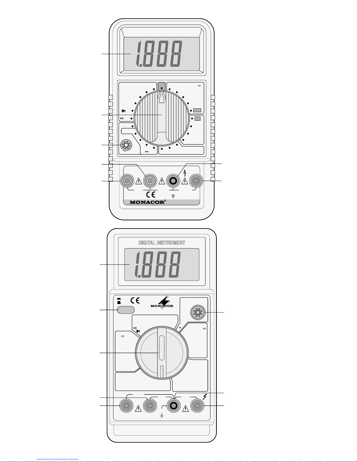
Bitte klappen Sie die Seite 3 heraus.
Sie sehen dann immer die beschriebenen Bedienelemente und Anschlüsse.
1 Übersicht der Bedienele-
mente und Anschlüsse
1 Display
2 separater Ein-/Ausschalter (nur bei
DMT-2560)
3 Bereichsschalter
4 Anschlußbuchse für die rote Meßlei-
tung (Pluspol) zur Strommessung
außer bei Messungen im 20-A-Bereich
5 Anschlußbuchse für die rote Meßlei-
tung (Pluspol) zur Strommessung im
20-A-Bereich
6 Steckanschlüsse zur Messung der
Stromverstärkung bei Transistoren
7 Anschlußbuchse „COM“ für die
schwarze Meßleitung (Minuspol)
8 Anschlußbuchse „V/Ω“ für die rote
Meßleitung (Pluspol) zur Spannungsund Widerstandsmessung
2 Hinweise für den sicheren
Gebrauch
Dieses Gerät entspricht der Richtlinie
für elektromagnetische Verträglichkeit
89/336/EWG und der Niederspannungsrichtlinie 73/23/EWG.
Mit diesem Instrument können lebensgefährlich hohe Spannungen gemessen werden. Bei Messungen von
Spannungen ab 42V ist besondere
Sorgfalt geboten. Achten Sie stets auf
den einwandfreien Zustand der Meßleitungen. Beschädigte Meßleitungen
müssen ausgetauscht werden.
Beachten Sie für den Betrieb auch unbedingt die folgenden Punkte:
●
Das Gerät ist nur zur Verwendung in
Räumen geeignet.
●
Schützen Sie das Gerät vor Feuchtigkeit und Hitze (zulässiger Einsatztemperaturbereich 0–40°C).
●
Wird das Gerät zweckentfremdet,
falsch bedient bzw. angeschlossen,
überlastet oder nicht fachgerecht repariert, kann für eventuelle Schäden
keine Haftung übernommen werden.
●
Für die Reinigung nur ein trockenes,
weiches Tuch verwenden, auf keinen
Fall Chemikalien oder Wasser.
●
Soll das Gerät endgültig aus dem
Betrieb genommen werden, übergeben Sie es zur Entsorgung einem
örtlichen Recyclingbetrieb.
3
V erwendungsmöglichkeiten
Dieses Digital-Multimeter dient zur Messung von Gleich- und Wechselspannungen, Gleich- und Wechselströmen sowie
Widerständen. Außerdem läßt sich bei
Dioden die Durchlaßspannung messen
und bei Transistoren die Stromverstärkung (hFE). Zur Durchgangsmessung ist
ein Summer vorhanden.
4 Inbetriebnahme
1) Den Drehschalter (3) auf den gewünschten Meßbereich stellen. Bei
dem Modell DMT-2560 zusätzlich das
Gerät mit dem Ein-/Ausschalter (2)
einschalten.
2) Im Display wird eine Anzeige sichtbar.
Wenn nicht, muß eine 9-V-Batterie
eingesetzt werden. Erscheint im Display das Symbol , die Batterie auswechseln — siehe Kapitel 6 „Batterie
oder Sicherung austauschen”.
3) Nach dem Betrieb immer das Gerät
ausschalten, sonst wird die Batterie
unnötig verbraucht:
DMT-2505 mit dem Drehschalter (3)
(Position „OFF”),
DMT-2560 mit dem Ein-/Ausschalter
(2). Dieses Modell schaltet auch automatisch aus, wenn es ca. 30 Minuten
nicht benutzt wird.
5 Messungen durchführen
Die schwarze Meßleitung immer in die
schwarze Buchse „COM“ (7) stecken und
die rote Meßleitung in eine der Messung
entsprechenden drei anderen Buchsen.
4
D
A
CH
Page 5

Für eine hohe Genauigkeit immer den
kleinstmöglichen Meßbereich wählen
(z. B. 15V im 20-V-Bereich messen und
nicht im 200-V-Bereich). Ist ein Meßbereich überschritten, signalisiert das Gerät
„1“ oder „
-
1“. In diesem Fall den nächst-
größeren Bereich wählen.
5.1 Spannungsmessung
●
Bei Messungen ab 42V besonders
sorgfältig vorgehen. Auf keinen Fall
das Meßobjekt oder die Meßspitzen
berühren.
●
Die maximal zu messende Spannung
darf folgende Werte nicht überschreiten. Andernfalls besteht für den Benutzer Lebensgefahr!
DMT-2505: 1000V oder 750V~
DMT-2560: 1000V oder 700V~
1) Die rote Meßleitung an die Buchse
„V/Ω“ (8) anschließen. Auf keinen Fall
versehentlich eine der beiden Buchsen für die Strommessung (4 oder 5)
verwenden! Das Meßgerät und die
Spannungsquelle können beschädigt
werden.
2) Bei W echselspannungen den Bereichsschalter (3) in einen der Bereiche „V~“
stellen, bei Gleichspannungen in einen
der Bereiche „V “.
3) Die Meßspitzen an das Meßobjekt
halten, und auf dem Display den
Meßwert ablesen.
4) Liegt bei Gleichspannungsmessungen an der roten Meßspitze der
Minuspol und an der schwarzen Meßspitze der Pluspol, erscheint im Display vor dem Meßwert ein Minuszeichen.
5.2 Strommessung
●
Der maximal zu messende Gleichstrom darf 20A nicht überschreiten.
●
Der 20-A-Meßstromkreis ist nicht abgesichert. Hier ist besondere Vorsicht
geboten.
●
Ist die rote Meßleitung an eine der
beiden Buchsen für die Strommessung (4 oder 5) angeschlossen, auf
keinen Fall eine Spannung auf das
Meßgerät geben. Das Meßgerät und
die Spannungsquelle können beschädigt werden.
1) Die rote Meßleitung in die Buchse (5)
stecken, wenn folgende Ströme gemessen werden sollen:
DMT-2505: 200mA–20A
DMT-2560: 2–20A
Den Bereichsschalter (3) in die Position „20“ bzw. „20A“ der Bereiche
„A “ bzw. „A~“ drehen.
Bei kleineren Strömen als oben
angegeben die rote Meßleitung in die
Buchse (4) stecken, und den Bereichsschalter in einen der Bereiche „A “
bzw . „A~“ drehen.
2) Den zu messenden Stromkreis auftrennen und mit dem Meßgerät verbinden. Im 20-A-Bereich nur kurzzeitig
(max. 15 Sek.) messen, sonst wird
durch die interne Erwärmung die Messung ungenau.
3) Liegt bei Gleichstrommessungen an
der roten Meßspitze der Minuspol und
an der schwarzen Meßspitze der Pluspol, erscheint im Display vor dem
Meßwert ein Minuszeichen.
5.3 Widerstandsmessung
●
Das Gerät ist kurzzeitig (max. 15 Sek.)
bis 250V /~ überlastgeschützt. Trotzdem nicht innerhalb einer Schaltung
messen, wenn diese unter Spannung
steht.
●
Einen Widerstand immer separat messen, sonst ist die Messung falsch.
Dazu muß er ggf. aus der Schaltung
herausgelötet werden.
1) Die rote Meßleitung an die Buchse
„V/Ω“ (8) anschließen.
2) Den Bereichsschalter (3) in einen der
Bereiche „Ω“ stellen. (Bei dem Modell
DMT-2505 ist im 200-Ω-Bereich
gleichzeitig der Durchgangssummer
aktiviert.)
3) Die Meßspitzen an den Widerstand
bzw. an die entsprechenden Meßpunkte halten.
5
D
A
CH
Page 6

5.4 Durchgangsprüfung
●
Das Gerät ist kurzzeitig (max. 15 Sek.)
bis 250V /~ überlastgeschützt. Trotzdem nicht innerhalb einer Schaltung
messen, wenn diese unter Spannung
steht.
1) Die rote Meßleitung an die Buchse
„V/Ω“ (8) anschließen.
2) Den Bereichsschalter (3) in die Position stellen.
3) Die Meßspitzen an die entsprechenden Meßpunkte halten. Der Summer
ertönt, wenn der Durchgangswiderstand die folgenden Werte unterschreitet:
DMT-2505: 50Ω
DMT-2560: 30Ω
5.5 Stromverstärkung bei Transi-
storen
1) Den Transistor seinen Anschlüssen
entsprechend (E, B, C) in die Steckanschlüsse (6) einsetzen. Für NPNT ypen die rechte Sockelhälfte verwenden und für PNP-Typen die linke
Sockelhälfte.
2) Den Drehschalter (3) in die Position
„hFE“ stellen.
3) Das Display zeigt die Stromverstärkung (max. 1000) bei einem Basisstrom (I
B) von ca. 10µA und einer Kol-
lektor-Emitter-Spannung (U
CE) von
ca. 2,8V an.
5.6 Durchlaßspannung bei Dioden
1) Die rote Meßleitung an die Buchse
„V/Ω“ (8) anschließen.
2) Den Drehschalter (3) in die Position
stellen.
3) Die Kathode der Diode an die
schwarze Meßspitze halten und die
Anode an die rote Meßspitze.
4) Das Display zeigt die Durchlaßspannung bei einem Teststrom von ca.
1mA in mV an.
Bei einer Anzeige von 0V hat die
Diode den Kurzschluß.
Bei der Anzeige „1“ ist die Diode
unterbrochen oder in Sperrichtung
angeschlossen (Diode umpolen).
6 Batterie oder Sicherung
austauschen
●
Vor dem Öffnen des Gerätes unbedingt die Meßleitungen von den Meßpunkten der Schaltung entfernen, um
jegliche Gefahr eines elektrischen
Schlages zu vermeiden.
●
Betreiben Sie das Gerät niemals im
geöffneten Zustand.
a. Wird im Display das Symbol ange-
zeigt, muß die 9-V-Batterie ausgetauscht werden.
b. Ist außer im 20-A-Bereich keine
Strommessung möglich, die Sicherung überprüfen und ggf. durch eine
gleichen Typs ersetzen. Folgende
Sicherung ist eingesetzt:
DMT-2505: 0,2A, flink
DMT-2560: 2A, flink
Das Gerät öffnen:
DMT-2505: Auf der Geräterückseite die
beiden Schrauben entfernen, und die
untere Gehäuseschale abnehmen.
DMT-2560: Für den Batteriewechsel nur
die untere Schraube entfernen, und den
Batteriefachdeckel abnehmen. Zum Austausch der Sicherung zusätzlich die vier
Schrauben der unteren Gehäuseschale
entfernen. Zwei Schrauben befinden sich
im Batteriefach.
Nach dem Austausch die Gehäuseschale festschrauben, bei dem Modell
DMT-2560 zusätzlich den Batteriefachdeckel. Erst dann das Instrument wieder
in Betrieb nehmen.
6
D
A
CH
Page 7
7 Technische Daten
*bei 23°C, ±5°C
Laut Angaben des Herstellers.
Änderungen vorbehalten.
7
D
A
CH
DMT-2505 DMT-2560
Gleichspannung
Genauigkeit*
≤ 200 V
1000V
Eingangswiderstand
200mV, 2V, 20V, 200V, 1000 V
±(0,5 % + 1 Digit)
±(0,8 % + 2 Digits)
10MΩ
200mV, 2V, 20V, 200V, 1000 V
±(0,5 % + 1 Digit)
±(0,8 % + 2 Digits)
10MΩ
Wechselspannung
Genauigkeit*
200mV
2–200V
750V bzw. 700 V
Frequenzbereich
≤ 200 V
750V bzw. 700 V
Eingangswiderstand
2V, 20V, 200V, 750V
—
±(0,8 % + 3 Digits)
±(1,2 % + 3 Digits)
40–400Hz
40–400Hz
10MΩ
200mV, 2V, 20V, 200V, 700 V
±(1,2 % + 3 Digits)
±(0,8 % + 3 Digits)
±(1,2 % + 3 Digits)
40–400Hz
40–200Hz
10MΩ
Gleichstrom
Genauigkeit*
≤ 20 mA
200mA
2A
20A
200µA, 2 mA, 20 mA, 200mA, 20 A
±(0,8 % + 1 Digit)
±(1,2 % + 1 Digit)
—
±(2,0 % + 5 Digits)
200µA, 2 mA, 20 mA, 200mA, 2 A, 20 A
±(0,8 % + 1 Digit)
±(1,2 % + 1 Digit)
±(1,2 % + 1 Digit)
±(2,0 % + 5 Digits)
Widerstand
Genauigkeit*
200Ω
2kΩ–2MΩ
20MΩ
200 Ω, 2 kΩ, 20 kΩ, 200 kΩ, 2 MΩ, 20 MΩ
±(0,8 % + 3 Digits)
±(0,8 % + 1 Digit)
±(1,0 % + 2 Digits)
200 Ω, 2 kΩ, 20 kΩ, 200 kΩ, 2 MΩ, 20 MΩ
±(0,8 % + 3 Digits)
±(0,8 % + 1 Digit)
±(1,0 % + 2 Digits)
Durchgangstest Summer < 50Ω Summer < 30Ω
Transistortest bei
Anzeige
UCE = 3 V, IB = 10 µA
Stromverstärkung 0–1000
UCE = 2,8 V, IB = 10 µA
Stromverstärkung 0–1000
Display
Meßrate
Stromversorgung
Einsatzbereich
Abmessungen
Gewicht
21-mm-LCD, 31/
2stellig
2–3 Messungen/Sek.
1 x 9-V-Batterie
0–40° C, < 75% Luftfeuchtigkeit
86 x 39 x 162mm
260g
21-mm-LCD, 31/
2stellig
2–3 Messungen/Sek.
1 x 9-V-Batterie
0–40° C, < 75% Luftfeuchtigkeit
88 x 43 x 175mm
360g
Wechselstrom
Genauigkeit*
200µA
2mA, 20mA
200mA
2A
20A
Frequenzbereich
2mA, 20mA, 200 mA, 20 A
—
±(1,2 % + 3 Digits)
±(1,8 % + 3 Digits)
—
±(3,0 % + 7 Digits)
40–400Hz
200µA, 2 mA, 20 mA, 200mA, 2 A, 20 A
±(1,8 % + 3 Digits)
±(1,2 % + 3 Digits)
±(2,0 % + 3 Digits)
±(2,0 % + 3 Digits)
±(3,0 % + 7 Digits)
40–400Hz
Diodentest-Meßstrom
Anzeige
0,8mA
Durchlaßspannung
1mA
Durchlaßspannung
Page 8

Please unfold page 3. Then you can
always see the operating elements
and connections described.
1 Operating Elements and
Connections
1 Display
2 Separate ON/OFF switch (only with
DMT-2560)
3 Range switch
4 Jack for the red test lead (positive
pole) for current measurement except for measurements in the 20A
range
5 Jack for the red test lead (positive
pole) for current measurement in the
20A range
6 Plug-in connections for measuring
the current amplification of transistors
7 Jack “COM” for the black test lead
(negative pole)
8 Jack “V/Ω” for the red test lead (posi-
tive pole) for voltage and resistance
measurements
2 Safety Notes
This appliance corresponds to the directive for electromagnetic compatibility
89/336 /EEC and the low voltage directive 73/23/EEC.
With this unit very high voltages dangerous to life can be measured. Be
especially careful with voltage measurements above 42 V. The test leads
must always be perfectly insulated.
Damaged test leads must be replaced.
Always watch the following items regarding the operation:
●
The unit is only suitable for indoor use.
●
Protect the unit from humidity and heat
(permissible ambient temperature range
0–40 °C).
●
If the unit is used for purposes other
than originally intended, if it is over-
loaded or operated, connected or re-
paired in the wrong way , there is no lia-
bility for possible damage.
●
Only use a dry, soft cloth for cleaning,
by no means chemicals or water.
●
If the unit is to be put out of operation
definitively, bring it to a local recycling
plant for disposal.
3 Applications
With this digital multimeter DC and AC
voltages, DC and AC currents as well as
resistances can be measured. Furthermore, the forward voltage of diodes and
the current amplification (hFE) of transistors can be measured. For the continuity
measurement a buzzer is provided.
4 Setting into Operation
1) Set the rotary switch (3) to the desired
measuring range. With model DMT2560 switch on the unit additionally
with the ON/OFF switch (2).
2) A display is shown. If not, a 9V battery
must be inserted. If the symbol is
displayed, replace the battery — see
chapter 6 “Replacing of Battery or
Fuse”.
3) After the operation always switch off
the unit, otherwise the battery will be
exhausted unnecessarily:
DMT-2505 with the rotary switch (3)
(position “OFF”)
DMT-2560 with the ON/OFF switch
(2). This model also switches off automatically if it is not used for approx.
30minutes.
5 Carrying out Measure-
ments
Always plug the black test lead into the
black jack “COM” (7) and the red test
lead into one of the three other jack
according to the measurement.
For a high accuracy always choose
the lowest possible measuring range
(e.g. measure 15 V in the 20 V range and
not in the 200 V range). If a measuring
range has been exceeded, the unit signalizes “1” or “
-
1”. In this case choose
the next higher range.
8
GB
Page 9

5.1 Voltage measurement
●
With measurements form 42 V on be
especially careful. In no case touch the
object to be measured or the test tips.
●
The voltage max. to be measured
must not exceed the following values.
Otherwise there is danger of life for
the user!
DMT-2505: 1000V or 750V~
DMT-2560: 1000V or 700V~
1) Connect the red test lead to jack “V/Ω”
(8). In no case accidentally use one of
both jacks for the current measurement (4 or 5)! The meter and the voltage source may be damaged.
2) With AC voltage measurements set
the range switch (3) into one of the
“V~” ranges, with DC voltages into
one of the “V ” ranges.
3) Hold the test tips at the measuring
object, and read the measuring value
from the display.
4) If with DC voltage measurements the
negative pole is at the red test tip and
the positive pole at the black test tip, a
minus sign is displayed before the
measuring value.
5.2 Current measurement
●
The DC current max. to be measured
must not exceed 20A.
●
The 20 A measuring current circuit is
not fused. Be especially careful in this
case.
●
If the red test lead is connected to one
of both jacks for the current measurement (4 or 5), in no case feed voltage
to the meter. The meter and the voltage source may be damaged.
1) Plug the red test lead into the jack (5)
if the following currents are to be
measured:
DMT-2505: 200mA–20A
DMT-2560: 2–20A
Turn the range switch (3) into position
“20” resp. “20A” of the “A ” resp. “A~”
ranges.
With lower currents than indicated
above plug the red test lead into the
jack (4), and turn the range switch into
one of the “A ” resp. “A~” ranges.
2) Open up the current circuit to be
measured and connect it with the
meter . In the 20A range measure only
for a short time (max. 15 seconds),
otherwise the measurement becomes
inexact due to the internal heating.
3) If with DC current measurements the
negative pole is at the red test tip and
the positive pole at the black test tip, a
minus sign is displayed before the
measuring value.
5.3 Resistance measurement
●
The unit is overload-protected up to
250V /~ for a short time (max.
15 seconds). In spite of this do not
measure within a circuit if it carries
voltage.
●
Always measure a resistor separately,
otherwise the measurement is wrong.
For this it must be soldered out of the
circuit, if necessary.
1) Connect the red test lead to jack “V/Ω”
(8).
2) Set the range switch (3) to one of the
“Ω” ranges. (Model DMT-2505: in the
200Ω range the continuity buzzer is
activated at the same time.)
3) Hold the test tips at the resistor resp. at
the corresponding measuring points.
5.4 Continuity test
●
The unit is overload-protected up to
250V /~ for a short time (max.
15 seconds). In spite of this do not
measure within a circuit if it carries
voltage.
1) Connect the red test lead to jack “V/Ω”
(8).
2) Set the range switch (3) to position .
3) Hold the test tips to the corresponding
measuring points. The buzzer sounds
if the resistance is below the following
values:
DMT-2505: 50Ω
DMT-2560: 30Ω
9
GB
Page 10

5.5 Current amplification with
transistors
1) Plug the transistor according to its ter-
minals (E, B, C) into the connector (6).
Use the right socket half for NPN
types and the left socket half for PNP
types.
2) Turn the rotary switch (3) into position
“hFE”.
3) The display shows the current amplifi-
cation (max. 1000) at a basic current
(I
B) of approx. 10µA and a voltage of
collector and emitter (U
CE) of approx.
2.8V.
5.6 Forward voltage with diodes
1) Connect the red test lead to jack “V/Ω”
(8).
2) Set the rotary switch (3) to position
.
3) Hold the cathode of the diode to the
black measuring tip and the anode to
the red measuring tip.
4) The display shows the forward voltage
at a test current of approx. 1mA in mV.
With a display of 0 V the diode has a
short circuit.
With the display “1” the diode is interrupted or connected in reverse direction (change the polarity of the diode).
6 Replacing of Battery or
Fuse
●
Prior to opening the unit in any case
remove the test leads from the measuring points of the circuit to avoid any
danger of an electric stroke.
●
Never use the unit if it has been
opened.
a. If the symbol is displayed, the 9V
battery must be replaced.
b. If no current measuring is possible
except in the 20A range, check the
fuse and replace it by one of the same
type, if necessary. The following fuse
has been inserted:
DMT-2505: 0.2A, quick-acting
DMT-2560: 2A, quick-acting
Open the unit:
DMT-2505: Remove both screws at the
rear side of the unit, and take off the
lower housing shell.
DMT-2560: For the battery replacement
only remove the lower screw , and take off
the cover of the battery compartment. To
replace the fuse, additionally remove the
four screws of the lower housing shell.
Two screws are in the battery compartment.
After the replacement screw the housing
shell, with model DMT-2560 additionally
screw the cover of the battery compartment. Only then use the instrument
again.
10
GB
Page 11
7 Specifications
*at 23°C, ±5°C
According to the manufacturer.
Subject to change.
11
GB
DMT-2505 DMT-2560
Direct voltage
Accuracy*
≤ 200 V
1000V
Input resistance
200mV, 2V, 20V, 200V, 1000 V
±(0.5 % + 1 digit)
±(0.8 % + 2 digits)
10MΩ
200mV, 2V, 20V, 200V, 1000 V
±(0.5 % + 1 digit)
±(0.8 % + 2 digits)
10MΩ
Alternating voltage
Accuracy*
200mV
2–200V
750V resp. 700V
Frequency range
≤ 200 V
750V resp. 700V
Input resistance
2V, 20V, 200V, 750V
—
±(0.8 % + 3 digits)
±(1.2 % + 3 digits)
40–400Hz
40–400Hz
10MΩ
200mV, 2V, 20V, 200V, 700 V
±(1.2 % + 3 digits)
±(0.8 % + 3 digits)
±(1.2 % + 3 digits)
40–400Hz
40–200Hz
10MΩ
Direct current
Accuracy*
≤ 20 mA
200mA
2A
20A
200µA, 2 mA, 20 mA, 200mA, 20 A
±(0.8 % + 1 digit)
±(1.2 % + 1 digit)
—
±(2.0 % + 5 digits)
200µA, 2 mA, 20 mA, 200mA, 2 A, 20 A
±(0.8 % + 1 digit)
±(1.2 % + 1 digit)
±(1.2 % + 1 digit)
±(2.0 % + 5 digits)
Resistance
Accuracy*
200Ω
2kΩ–2MΩ
20MΩ
200 Ω, 2 kΩ, 20 kΩ, 200 kΩ, 2 MΩ, 20 MΩ
±(0.8 % + 3 digits)
±(0.8 % + 1 digit)
±(1.0 % + 2 digits)
200 Ω, 2 kΩ, 20 kΩ, 200 kΩ, 2 MΩ, 20 MΩ
±(0.8 % + 3 digits)
±(0.8 % + 1 digit)
±(1.0 % + 2 digits)
Continuity test buzzer < 50Ω buzzer < 30Ω
Transistor test at
Display
UCE = 3 V, IB = 10 µA
current amplification 0–1000
UCE = 2.8 V, IB = 10 µA
current amplification 0–1000
Display
Measuring rate
Power supply
Operating range
Dimensions
Weight
21-mm-LCD, 31/
2digits
2–3 measurements/s
1 x 9V battery
0–40° C, < 75% humidity
86 x 39 x 162mm
260g
21-mm-LCD, 31/
2digits
2–3 measurements/s
1 x 9V battery
0–40° C, < 75% humidity
88 x 43 x 175mm
360g
Alternating current
Accuracy*
200µA
2mA, 20mA
200mA
2A
20A
Frequency range
2mA, 20mA, 200 mA, 20 A
—
±(1.2 % + 3 digits)
±(1.8 % + 3 digits)
—
±(3.0 % + 7 digits)
40–400Hz
200µA, 2 mA, 20 mA, 200mA, 2 A, 20 A
±(1.8 % + 3 digits)
±(1.2 % + 3 digits)
±(2.0 % + 3 digits)
±(2.0 % + 3 digits)
±(3.0 % + 7 digits)
40–400Hz
Diode test measuring current
Display
0.8mA
forward voltage
1mA
forward voltage
Page 12

Ouvrez le présent livret page 3 de
manière à visualiser les éléments et
branchements.
1 Eléments et branchements
1 Affichage
2 Interrupteur Marche/Arrêt séparé (uni-
quement sur le modèle DMT -2560)
3 Sélecteur
4 Prise de branchement pour le cordon
de mesure rouge (pôle plus): mesures de courant excepté pour les mesures dans la plage 20A
5 Prise de branchement pour le cordon
de mesure rouge (pôle plus) dans la
plage 20A
6 Bornes pour mesurer l’amplification
de courant de transistors
7 Prise de branchement “COM” pour le
cordon de mesure noir (pôle moins)
8 Prise de branchement “V/Ω” pour le
cordon de mesure rouge (pôle plus):
mesures de tension et de résistance
2 Conseils d’utilisation
Ce multimètre répond à la norme européenne 89/336/CEE relative à la compatibilité électromagnétique à la norme
73/23/CEE portant sur les appareils à
basse tension.
Ce multimètre permet d’effectuer des
mesures de tensions élevées dangereuses: pour des mesures de tensions
supérieures à 42V, soyez particulièrement prudent. Veillez au bon état des
cordons de mesure. Tout cordon endommagé doit être remplacé.
Respectez scrupuleusement les points
suivants:
●
Cet appareil n’est conçu que pour une
utilisation en intérieur.
●
Protégez-le de l’humidité et de la chaleur (température d’utilisation autorisée
0–40 °C).
●
Nous déclinons toute responsabilité en
cas de dommage si l’appareil n’est pas
correctement utilisé, branché, réparé,
en cas de surcharge ou s’il est utilisé
dans un but autre que celui pour lequel
il a été conçu.
●
Pour le nettoyer , utilisez un chiffon sec
et souple, en aucun cas de produits
chimiques ou d’eau.
●
Lorsque l’appareil est définitivement
retiré du circuit de distribution, vous
devez le déposer dans une usine de
recyclage adaptée.
3 Possibilités d’utilisation
Le multimètre digital permet d’effectuer
des mesures de tensions continue et
alternative, de courants continu et alternatif et de résistances. Vous pouvez
également mesurer la tension de passage de diodes et l’amplification de courant (hFE) de transistors. Pour des tests
de continuité, l’appareil est équipé d’un
buzzer.
4 Utilisation
1) Mettez le sélecteur (3) sur la plage de
mesure souhaitée. Sur le modèle
DMT-2560, le multimètre s’allume
additionnellement avec l’interrupteur
Marche/Arrêt (2).
2) Vous pouvez lire une valeur sur l’affichage. Si ce n’est pas le cas, insérez
une batterie 9V. Si le symbole
apparaît, remplacez la batterie (voir
chapitre 6 “Remplacement de la batterie ou du fusible”).
3) Après utilisation, débranchez toujours
l’appareil sinon la batterie est utilisée
inutilement:
DMT-2505: sélecteur (3) sur la position “OFF”,
DMT-2560: interrupteur (2); ce modèle
se coupe automatiquement après une
non utilisation de 30 minutes env.
5 Mesures
Mettez toujours le cordon de mesure noir
dans la prise noire “COM” (7) et le cordon
rouge dans une des trois autres prises en
fonction du type de mesure à effectuer.
12
F
B
CH
Page 13

Pour une meilleure précision, sélectionnez toujours la plage de mesure la
plus petite (par exemple mesurez 15V
dans la plage 20V et pas dans la plage
200V). En cas de dépassement d’une
plage, l’appareil affiche “1” ou “
-
1”. Dans
ce cas, sélectionnez la plage immédiatement supérieure.
5.1 Mesures de tension
●
Pour des mesures à partir de 42V,
soyez particulièrement prudent. En
aucun cas, vous ne devez toucher les
pointes de touche ou l’objet à mesurer .
●
La tension maximale à mesurer ne
doit pas dépasser les valeurs suivantes sinon vous pourriez vous électrocuter:
DMT-2505: 1000V ou 750V~
DMT-2560: 1000V ou 700V~
1) Branchez le cordon de mesure rouge
dans la prise “V/Ω” (8). En aucun cas
n’utilisez une des deux prises prévues
pour les mesures de courant (4 ou 5).
Vous pourriez endommager le multimètre et la source de tension.
2) Pour des tensions alternatives, mettez
le sélecteur (3) sur une des plages
“V~”, pour des tensions continues, sur
une des plages “V ”.
3) Maintenez les pointes de touche sur
l’objet à mesurer, lisez la valeur sur
l’affichage.
4) Si, lors de mesures de tension conti-
nue, le pôle moins est à la pointe de
touche rouge et le pôle plus à la pointe
de touche noire, l’affichage indique
devant la valeur mesurée un signe
moins.
5.2 Mesures de courant
●
Le courant maximal pouvant être mesuré ne doit pas dépasser 20A.
●
Le circuit 20A ne dispose pas de fusible. Faites attention.
●
Si le cordon de mesure rouge est
branché à une des deux prises de
mesure de courant (4 ou 5), n’appliquez pas de tension sur le multimètre.
V ous pourriez endommager ce dernier
ainsi que la source de tension.
1) Mettez le cordon de mesure rouge
dans la prise (5) lorsque les courants
suivants doivent être mesurés:
DMT-2505: 200mA–20A
DMT-2560: 2–20A
Mettez le sélecteur (3) sur la position
“20”/“20 A” dans la plage “A ”/“A~”.
Pour des courants plus faibles que
susmentionnés, mettez le cordon de
mesure rouge dans la prise (4) et le
sélecteur sur une des plages “A ” ou
“A~”.
2) Ouvrez le circuit à mesurer et reliez-le
au multimètre. Les mesures dans la
plage 20Adoivent être très brèves (15
secondes maximum) car la chaleur
interne rend la mesure imprécise.
3) Si pour des mesures de courant continu, le pôle moins est à la pointe de
touche rouge et le pôle plus à la pointe
de touche noire, l’affichage indique
devant la valeur mesurée, un signe
moins.
5.3 Mesures de résistance
●
Le multimètre est protégé contre les
surcharges jusqu’à 250V /~. N’effectuez pas de mesure dans un circuit
porteur de tension.
●
Mesurez toujours une résistance séparément sinon la mesure est fausse.
Si besoin est, retirez-la de la platine.
1) Branchez le cordon rouge à la prise
“V/Ω” (8).
2) Mettez le sélecteur (3) sur une des
plages “Ω”. (Sur le modèle DMT -2505,
dans la plage 200Ω, un buzzer est
simultanément activé.)
3) Maintenez les pointes de touche sur la
résistance ou sur les points à mesurer .
5.4 Buzzer de continuité
●
Le multimètre est protégé contre les
surcharges jusqu’à 250V /~. N’effectuez pas de mesure dans un circuit
porteur de tension.
1) Branchez le cordon de mesure rouge
sur la prise “V/Ω” (8).
13
F
B
CH
Page 14

2) Mettez le sélecteur (3) sur la position
.
3) Maintenez les pointes sur les points à
mesurer. Le buzzer retentit lorsque la
résistance de passage est inférieure
aux valeurs suivantes:
DMT-2505: 50 Ω
DMT-2560: 30 Ω
5.5 Amplification de courant pour
transistors
1) Mettez le transistor dans les bornes
(6) correspondantes (E, B, C). Pour
les types NPN, utilisez la moitié droite
de la fiche et pour les types PNP, la
moitié gauche.
2) Mettez le sélecteur (3) sur la position
“hFE”.
3) L’affichage indique l’amplification
(1000 maximum) pour un courant de
base (I
B) de 10µA environ et pour une
tension de collecteur/émetteur U
CE de
2,8V environ.
5.6 Tension de passage de diodes
1) Branchez le cordon rouge à la prise
“V/Ω” (8).
2) Mettez le sélecteur (3) sur la position
.
3) Maintenez la cathode de la diode sur
la pointe de touche noire et l’anode
sur la pointe de touche rouge.
4) L’affichage indique en mV, la tension
de passage pour un courant test de
1mA environ.
Affichage de 0 V la diode a un courtcircuit.
Affichage “1” la diode est interrompue
ou branchée en sens inverse (inversion de polarité).
6 Remplacement de la batte-
rie ou du fusible
●
Retirez impérativement les cordons
des points à mesurer du circuit avant
d’ouvrir le multimètre pour éviter tout
choc électrique.
●
Ne faites jamais fonctionner l’appareil
s’il est ouvert.
a. Si l’affichage indique , remplacez
la batterie.
b. Si aucune mesure de courant n’est
possible sauf dans la plage 20A, vérifiez le fusible et remplacez-le, le cas
échéant, par un fusible du même type.
DMT-2505: 0,2A, rapide
DMT-2560: 2A, rapide
Ouverture du multimètre:
DMT-2505: Retirez les deux vis de la
face arrière puis la partie inférieure du
boîtier.
DMT-2560: Pour remplacer la batterie,
retirez la vis inférieure et retirez le couvercle du compartiment batterie. Pour
remplacer le fusible, vous devez également retirer les quatre vis de la partie
inférieure du boîtier . Deux vis se trouvent
dans le compartiment batterie.
Une fois l’opération terminée, revissez le
boîtier et sur le modèle DMT-2560, additionnellement le compartiment batterie.
Vous pouvez alors faire fonctionner le
multimètre.
14
F
B
CH
Page 15

*à 23°C, ±5°C
D’après les données du constructeur.
Tout droit de modification réservé.
15
F
B
CH
7 Caractéristiques techniques
DMT-2505 DMT-2560
Tension continue
Précision*
≤ 200 V
1000V
Résistance d’entrée
200mV, 2V, 20V, 200V, 1000 V
±(0,5 % + 1 digit)
±(0,8 % + 2 digits)
10MΩ
200mV, 2V, 20V, 200V, 1000 V
±(0,5 % + 1 digit)
±(0,8 % + 2 digits)
10MΩ
Tension alternative
Précision*
200mV
2–200V
750V/700 V
Bande passante
≤ 200 V
750V/700 V
Résistance d’entrée
2V, 20V, 200V, 750V
—
±(0,8 % + 3 digits)
±(1,2 % + 3 digits)
40–400Hz
40–400Hz
10MΩ
200mV, 2V, 20V, 200V, 700 V
±(1,2 % + 3 digits)
±(0,8 % + 3 digits)
±(1,2 % + 3 digits)
40–400Hz
40–200Hz
10MΩ
Courant continu
Précision*
≤ 20 mA
200mA
2A
20A
200µA, 2 mA, 20 mA, 200mA, 20 A
±(0,8 % + 1 digit)
±(1,2 % + 1 digit)
—
±(2,0 % + 5 digits)
200µA, 2 mA, 20 mA, 200mA, 2 A, 20 A
±(0,8 % + 1 digit)
±(1,2 % + 1 digit)
±(1,2 % + 1 digit)
±(2,0 % + 5 digits)
Résistance
Précision*
200Ω
2kΩ–2MΩ
20MΩ
200 Ω, 2 kΩ, 20 kΩ, 200 kΩ, 2 MΩ, 20 MΩ
±(0,8 % + 3 digits)
±(0,8 % + 1 digit)
±(1,0 % + 2 digits)
200 Ω, 2 kΩ, 20 kΩ, 200 kΩ, 2 MΩ, 20 MΩ
±(0,8 % + 3 digits)
±(0,8 % + 1 digit)
±(1,0 % + 2 digits)
Test de passage buzzer < 50Ω buzzer < 30Ω
Test de transistor à
Affichage
UCE = 3 V, IB = 10 µA
amplification courant 0–1000
UCE = 2,8 V, IB = 10 µA
amplification courant 0–1000
Affichage
Taux de mesure
Alimentation
Température d’utilisation
Dimensions
Poids
21-mm-LCD, 31/2
digits
2–3 mesures/sec.
1 x batterie 9V
0–40° C, < 75% humidité
86 x 39 x 162mm
260g
21-mm-LCD, 31/2
digits
2–3 mesures/sec.
1 x batterie 9V
0–40° C, < 75% humidité
88 x 43 x 175mm
360g
Courant alternatif
Précision*
200µA
2mA, 20mA
200mA
2A
20A
Bande passante
2mA, 20mA, 200 mA, 20 A
—
±(1,2 % + 3 digits)
±(1,8 % + 3 digits)
—
±(3,0 % + 7 digits)
40–400Hz
200µA, 2 mA, 20 mA, 200mA, 2 A, 20 A
±(1,8 % + 3 digits)
±(1,2 % + 3 digits)
±(2,0 % + 3 digits)
±(2,0 % + 3 digits)
±(3,0 % + 7 digits)
40–400Hz
Test de diodes - courant de mes.
Affichage
0,8mA
tension de passage
1mA
tension de passage
Page 16

Vi preghiamo di aprire completamente
la pagina 3. Così vedrete sempre gli
elementi di comando e i collegamenti
descritti.
1 Elementi di comando e
collegamenti
1 Display
2 Interruttore on / off separato (solo per
DMT-2560)
3 Selettore campo
4 Presa per il cavetto rosso (polo posi-
tivo) per misura corrente, eccetto il
campo di 20A
5 Presa per il cavetto rosso (polo posi-
tivo) per misura corrente nel campo
20A
6 Prese per misurare il guadagno in
corrente per transistor
7 Presa “COM” per il cavetto nero (polo
negativo)
8 Presa “V/Ω” per il cavetto rosso (polo
positivo) per misura tensione e resistenza
2 Avvertenze di sicurezza
Quest’apparecchio corrisponde alle direttive CE 89 /336 /CEE sulla compatibilità elettromagnetica e 73/23/CEE per
apparecchi a bassa tensione.
Con quest’apparecchio si possono misurare tensioni alte pericolose. Fare
molta attenzione durante le misure con
tensioni oltre 42V. Controllare sempre
lo stato perfetto dei cavetti di misura e
sostituire i cavetti danneggiati.
Durante l’uso si devono osservare assolutamente i seguenti punti:
●
Lo strumento è previsto solo per l’uso
all’interno di locali.
●
Proteggere l’apparecchio dall’umidità
e dal calore (temperatura d’impiego
ammessa fra 0 e 40°C).
●
Nel caso di uso improprio, di impiego o
collegamento scorretto, di sovraccarica o di riparazione non a regola d’arte
non si assume nessuna responsabilità
per eventuali danni.
●
Per la pulizia usare solo un panno morbido asciutto; non impiegare in nessun
caso prodotti chimici o acqua.
●
Se si desidera eliminare l’apparecchio
definitivamente, consegnarlo per lo
smaltimento ad un’istituzione locale
per il riciclaggio.
3 Possibilità d’impiego
Questo multimetro digitale serve per
misurare tensioni continue ed alternate,
correnti continue ed alternate nonché
resistenze. Inoltre, nei diodi è possibile la
prova di continuità e per i transistor si
può misurare il guadagno in corrente
(hFE). Per la prova di continuità è presente un buzzer.
4 Messa in funzione
1) Portare il selettore (3) sul campo desiderato. Nel modello DMT -2560 accendere lo strumento con l’interruttore
on/off (2).
2) Sul display si vedono delle indicazioni.
Altrimenti, occorre inserire una batteria a 9V. Se sul display appare il simbolo sostituire la batteria – vedi
capitolo 6 “Sostituire batterie e fusibili”.
3) Dopo l’uso, spegnere il tester per non
consumare inutilmente la batteria:
DMT-2505 con il selettore (3) (posizione “OFF”)
DMT-2560 con l’interruttore on/off (2).
Questo modello si spegne automaticamente se non viene usato per 30
minuti circa.
5 Esecuzione di misure
Inserire il cavetto nero nella presa nera
“COM” (7) e quello rosso in una delle tre
prese restanti, a seconda del tipo di
misura.
Per aumentare la precisione, selezionare sempre il campo più basso possibile
(p.es. per misurare 15V selezionare il
campo 20 V anziché 200 V). Se si supera
un campo, lo strumento segnala “1”
16
I
Page 17

oppure “-1”. In questo caso selezionare
il campo adeguato.
5.1 Misura tensione
●
Procedere con molta cautela nella misura di tensioni oltre i 42 V. Non toccare in nessun modo l’oggetto da misurare o i puntali.
●
La tensione massima non deve superare i seguenti valori. Altrimenti c’è
pericolo di vita per l’utente!
DMT-2505: 1000V opp. 750V~
DMT-2560: 1000V opp. 700V~
1) Il cavetto rosso dev’essere inserito
nella presa “V/Ω” (8) e in nessun caso
in una delle due prese per la misura di
corrente (4 o 5)! In quest’ultimo caso,
lo strumento e la sorgente di tensione
potrebbero risultare danneggiati.
2) Per le tensioni alternate posizionare il
selettore (3) su uno dei campi “V~”,
per le tensioni continue su uno dei
campi “V ”.
3) Con i puntali toccare l’oggetto da misurare e leggere il valore misurato sul
display.
4) Se nelle tensioni continue, il puntale
rosso tocca il polo negativo e il puntale
nero quello positivo, sul display, davanti al valore misurato, appare il
segno negativo (
-
).
5.2 Misura corrente
●
La corrente continua massima da
misurare non deve superare i 20A.
●
Il circuito 20A non è protetto. Bisogna
procedere con molta cautela.
●
Se il cavetto rosso è inserito in una
delle due prese per la misura della
corrente (4 o 5), non applicare in nessun caso una tensione. Il multimetro e
la sorgente di tensione potrebbero
subire dei danni.
1) Per le seguenti correnti inserire il
cavetto rosso nella presa (5):
DMT-2505: 200mA–20A
DMT-2560: 2–20A
Girare il selettore (3) rispettivamente
su “20” o “20A” dei campi “A ” o “A~”.
Per le correnti minori inserire il cavetto
rosso nella presa (4) e girare il selettore su uno dei campi “A ” o “A~”.
2) Aprire il circuito da misurare e collegarlo con lo strumento. Fare solo misure brevi nel campo 20A (max.
15sec.); infatti, il calore interno rende
la misura meno precisa.
3) Se nelle misure di corrente continua, il
polo negativo è collegato con il puntale
rosso e il polo positivo con il puntale
nero, sul display appare il segno negativo (
-
) davanti al valore di misura.
5.3 Misura resistenza
●
Lo strumento è protetto, per breve
tempo (max. 15 sec.), contro i sovraccarichi fino a 250V /~. Ciononostante non eseguire misure all’interno di
un circuito sotto tensione!
●
Misurare una resistenza sempre separatamente per aver valori corretti.
Eventualmente dissaldarla dal circuito.
1) Il cavetto rosso dev’essere inserito
nella presa “V/Ω” (8).
2) Posizionare il selettore (3) su uno dei
campi “Ω”. (Nel modello DMT-2505,
nel campo 200Ω è attivato contemporaneamente il buzzer di continuità.)
3) Mettere i puntali in contatto con la resistenza o con i punti da misurare.
5.4 Prova di continuità
●
Lo strumento è protetto, per breve
tempo (max. 15sec.), contro i sovraccarichi fino a 250V /~. Ciononostante non eseguire misure all’interno di
un circuito sotto tensione!
1) Il cavetto rosso dev’essere inserito
nella presa “V/Ω” (8).
2) Posizionare il selettore (3) su .
3) Mettere i puntali in contatto con i punti
da misurare. Il buzzer suona, se la
resistenza di continuità rimane sotto i
seguenti valori:
DMT-2505: 50Ω
DMT-2560: 30Ω
17
I
Page 18

5.5 Guadagno in corrente
con transistor
1) Inserire il transistor nelle prese (6) a
seconda dei suoi contatti (E, B, C).
Per i tipi NPN utilizzare il lato di destra
e per i tipi PNP il lato di sinistra.
2) Portare il selettore (3) in posizione
“hFE”.
3) Il display segnala il guadagno in cor-
rente (max. 1000) con una corrente
base (I
B) di 10 µA circa e con una ten-
sione emettitore-collettore (U
CE) di
2,8V circa.
5.6 Prova di continuità per diodi
1) Il cavetto rosso dev’essere inserito
nella presa “V/Ω” (8).
2) Posizionare il selettore (3) su .
3) Mettere il puntale nero in contatto con
il catodo del diodo e il puntale rosso
con l’anodo.
4) Il display indica la tensione di conti-
nuità in mV, con una corrente di test di
ca. 1mA.
L’indicazione 0V significa cortocircuito
del diodo.
L’indicazione “1” significa che il diodo
è interrotto o che è collegato in senso
di non conduzione (allora invertire la
polarità).
6 Sostituire batterie e fusibili
●
Prima di aprire lo strumento staccare i
cavetti dal circuito per evitare ogni
pericolo di scossa elettrica.
●
Mai far funzionare lo strumento quando è aperto.
a. Se il display indica il simbolo ,
occorre sostituire la batteria 9V.
b. Se al di fuori del campo 20A non è
possibile nessuna misura, conviene
controllare il fusibile e sostituirlo eventualmente con uno dello stesso tipo.
I fusibili sono:
DMT-2505: 0,2A, rapido
DMT-2560: 2A, rapido
Apertura dello strumento:
DMT-2505: Svitare le due viti sul retro e
staccare la parte inferiore del contenitore.
DMT-2560: Per sostituire la batteria svitare solo la vite inferiore e staccare il
coperchio del vano batteria. Per la sostituzione del fusibile svitare anche le
quattro viti della parte inferiore del contenitore. Due di queste viti si trovano nel
vano batteria.
Dopo la sostituzione richiudere bene il
contenitore con le viti, nel modello DMT2560 chiudere bene anche il coperchio
del vano batteria. Solo allora rimettere in
funzione lo strumento.
18
I
Page 19

7 Dati tecnici
*con 23°C, ±5°C.
Dati forniti dal costruttore.
Con riserva di modifiche tecniche.
19
I
DMT-2505 DMT-2560
Tensione continua
Precisione*
≤ 200 V
1000V
Resistenza d’ingresso
200mV, 2V, 20V, 200V, 1000 V
±(0,5 % + 1 digit)
±(0,8 % + 2 digits)
10MΩ
200mV, 2V, 20V, 200V, 1000 V
±(0,5 % + 1 digit)
±(0,8 % + 2 digits)
10MΩ
Tensione alternata
Precisione*
200mV
2–200V
750V o. 700V
Campo di frequenza
≤ 200 V
750V o. 700V
Resistenza d’ingresso
2V, 20V, 200V, 750V
—
±(0,8 % + 3 digits)
±(1,2 % + 3 digits)
40–400Hz
40–400Hz
10MΩ
200mV, 2V, 20V, 200V, 700 V
±(1,2 % + 3 digits)
±(0,8 % + 3 digits)
±(1,2 % + 3 digits)
40–400Hz
40–200Hz
10MΩ
Corrente continua
Precisione*
≤ 20 mA
200mA
2A
20A
200µA, 2 mA, 20 mA, 200mA, 20 A
±(0,8 % + 1 digit)
±(1,2 % + 1 digit)
—
±(2,0 % + 5 digits)
200µA, 2 mA, 20 mA, 200mA, 2 A, 20 A
±(0,8 % + 1 digit)
±(1,2 % + 1 digit)
±(1,2 % + 1 digit)
±(2,0 % + 5 digits)
Resistenza
Precisione*
200Ω
2kΩ–2MΩ
20MΩ
200 Ω, 2 kΩ, 20 kΩ, 200 kΩ, 2 MΩ, 20 MΩ
±(0,8 % + 3 digits)
±(0,8 % + 1 digit)
±(1,0 % + 2 digits)
200 Ω, 2 kΩ, 20 kΩ, 200 kΩ, 2 MΩ, 20 MΩ
±(0,8 % + 3 digits)
±(0,8 % + 1 digit)
±(1,0 % + 2 digits)
Prova di continuità buzzer < 50Ω buzzer < 30Ω
Prova transistor con
Visualizzazione
UCE = 3 V, IB = 10 µA
guadagno in corrente 0–1000
UCE = 2,8 V, IB = 10 µA
guadagno in corrente 0–1000
Display
Campionamento
Alimentazione
Campo d’impiego
Dimensioni
Peso
21-mm-LCD, 31/2
cifre
2–3 misure/sec.
1 x batteria 9V
0–40° C, umidità < 75%
86 x 39 x 162mm
260g
21-mm-LCD, 31/2
cifre
2–3 misure/sec.
1 x batteria 9V
0–40° C, umidità < 75%
88 x 43 x 175mm
360g
Corrente alternata
Precisione*
200µA
2mA, 20mA
200mA
2A
20A
Campo di frequenza
2mA, 20mA, 200 mA, 20 A
—
±(1,2 % + 3 digits)
±(1,8 % + 3 digits)
—
±(3,0 % + 7 digits)
40–400Hz
200µA, 2 mA, 20 mA, 200mA, 2 A, 20 A
±(1,8 % + 3 digits)
±(1,2 % + 3 digits)
±(2,0 % + 3 digits)
±(2,0 % + 3 digits)
±(3,0 % + 7 digits)
40–400Hz
Corr. di misura della prova diodi
Visualizzazione
0,8mA
tensione di continuità
1mA
tensione di continuità
Page 20

Vouw bladzijde 3 helemaal open, zodat u steeds een overzicht hebt van de
beschreven bedieningselementen en
de aansluitingen.
1 Overzicht van de
bedieningselementen
en aansluitingen
1 Display
2 Afzonderlijke Aan/Uit-schakelaar (en-
kel bij DMT -2560)
3 Keuzeschakelaar
4 Jack voor het rode meetsnoer (posi-
tieve pool) voor stroommeting, behalve bij metingen in het 20A-bereik
5 Jack voor het rode meetsnoer (posi-
tieve pool) voor stroommeting in het
20A-bereik
6 Stekkeraansluiting voor meting van
de stroomversterking bij transistoren
7 “COM”-jack voor het zwarte meets-
noer (negatieve pool)
8 “V/Ω”-jack voor het rode meetsnoer
(positieve pool) voor meting van
spanning en weerstand
2 Veiligheidsvoorschriften
Dit toestel is in overeenstemming met de
EU-richtlijnen 89/336/EEG voor elektromagnetische compatibiliteit en 73/23/EEG
voor toestellen op laagspanning.
Met dit instrument kunnen hoge levensgevaarlijke spanningen gemeten
worden. Bij het meten van spanningen
vanaf 42 V dient u zeer zorgvuldig te
werk te gaan. Zorg ervoor, dat de
meetsnoeren zich steeds in een onberispelijke staat bevinden. Vervang
beschadigde meetsnoeren.
Let bij ingebruikname eveneens op het
volgende:
●
Het toestel is enkel geschikt voor gebruik binnenshuis.
●
Vermijd uitzonderlijk warme plaatsen
en plaatsen met een hoge vochtigheid
(toegestaan omgevingstemperatuurbereik: 0–40°C).
●
In geval van ongeoorloofd of verkeerd
gebruik, verkeerde aansluiting, overbelasting of herstelling door een nietgekwalificeerd persoon vervalt de garantie bij eventuele schade.
●
V erwijder het stof enkel met een droge
doek. Gebruik zeker geen chemicaliën
of water.
●
Wanneer het apparaat definitief uit
bedrijf genomen wordt, bezorg het dan
voor verwerking aan een plaatselijk
recyclagebedrijf.
3 Toepassingen
Deze digitale multimeter dient voor de
meting van gelijk- en wisselspanningen,
gelijk- en wisselstromen en weerstanden.
Bovendien kan het toestel bij dioden
gebruikt worden voor de meting van de
doorlaatspanning en bij transistoren voor
de meting van de stroomversterking
(hFE). V oor de doorgangsmeting beschikt
de multimeter over een zoemer .
4 Ingebruikname
1) Plaats de keuzeschakelaar (3) in het
juiste meetbereik. Schakel het model
DMT-2560 met behulp van de Aan/
Uit-schakelaar (2) in.
2) Op het display wordt informatie weergegegen. Indien dit niet het geval is,
brengt u een 9V-batterij aan. Vervang
de batterij, wanneer op het display het
symbool verschijnt – zie hoofdstuk
6 “Batterij of zekering vervangen”.
3) Schakel de multimeter na gebruik
steeds uit. Zo vermijdt u onnodig verbruik van de batterij:
model DMT-2505 met de keuzeschakelaar (3) (stand “OFF”),
model DMT-2560 met de Aan/Uitschakelaar (2). Dit model schakelt ook
automatisch uit, wanneer het ca. 30
minuten niet gebruikt wordt.
5 Metingen uitvoeren
Steek het zwarte meetsnoer in de zwarte
“COM”-jack (7) en het rode meetsnoer
20
NL
B
Page 21

afhankelijk van de soort meting in een
van de drie andere jacks.
Selecteer steeds het kleinst mogelijke
meetbereik voor een hogere nauwkeurigheid (bv. meet 15V in het 20V-bereik en
niet in het 200V-bereik). Bij overschrijding van het meetbereik signaliseert de
multimeter “1” of “
-
1”. Selecteer in dit ge-
val het eerstvolgende grotere bereik.
5.1 Meting van de spanning
●
Ga bij metingen vanaf 42V zeer zorgvuldig te werk. Raak het meetobject of
de meetpennen in geen geval aan.
●
De maximaal te meten spanning mag
de volgende waarden niet overschrijden. Anders dreigt er levensgevaar
voor de gebruiker!
DMT-2505: 1000V of 750V~
DMT-2560: 1000V of 700V~
1) Verbind het rode meetsnoer met de
jack “V/Ω” (8). Zorg ervoor, dat u niet
per ongeluk een van beide jacks voor
de meting van de stroom (4 of 5)
gebruikt! Het meettoestel en de spanningsbron kunnen immers beschadigd
worden.
2) Plaats de keuzeschakelaar (3) bij wis-
selspanningen in een van de “V~”bereiken, bij gelijkspanningen in een
van de “V ”-bereiken.
3) Houd de meetpennen tegen het meet-
object en lees de waarde van het display af.
4) Wanneer bij de meting van gelijkspan-
ningen de rode meetpen met de negatieve pool en de zwarte meetpen met
de positieve pool verbonden wordt,
dan verschijnt op het display een minteken vóór de gemeten waarde.
5.2 Meting van de stroom
●
De maximaal te meten gelijkstroom
mag niet meer dan 20A bedragen.
●
De 20A-meetstroomkring is niet beveiligd. Wees hier bijzonder voorzichtig.
●
Bij verbinding van het rode meetsnoer
met een van beide jacks voor de
stroommeting (4 of 5), leid dan in geen
geval spanning naar het meettoestel.
Het meettoestel en de spanningsbron
kunnen immers beschadigd worden.
1) Verbind het rode meetsnoer met jack
(5) bij meting van de volgende stroomwaarden:
DMT-2505: 200mA – 20A
DMT-2560: 2–20A
Draai de bereikschakelaar (3) in de
stand “20” resp. “20A” van de bereiken
“A” resp. “A~”.
Bij stroomwaarden die kleiner zijn
dan hierboven aangegeven, dient u
het rode meetsnoer met jack (4) te
verbinden en de keuzeschakelaar in
een van de bereiken “A ” resp. “A~”
te draaien.
2) Maak de te meten stroomkring los en
verbind deze met het meettoestel.
Voer in het 20A-bereik slechts een
korte meting (max. 15sec.) uit, anders
wordt de meting door de interne opwarming onnauwkeurig.
3) Wanneer bij de meting van gelijkstromen de rode meetpen met de negatieve pool en de zwarte meetpen met
de positieve pool verbonden wordt,
dan verschijnt op het display een minteken vóór de gemeten waarde.
5.3 Meting van de weerstand
●
Het toestel is korte tijd (max. 15sec.)
tot 250V /~ tegen overspanning beveiligd. Meet evenwel niet binnen een
schakeling, wanneer deze onder
spanning staat.
●
Meet een weerstand altijd afzonderlijk,
anders is de meting niet correct. Hiervoor moet de component soms uit de
schakeling losgesoldeerd worden.
1) Verbind het rode meetsnoer met de
jack “V/Ω” (8).
2) Plaats de keuzeschakelaar (3) in een
van de “Ω”-bereiken. (Bij het model
DMT -2505 is in het 200Ω-bereik tegelijkertijd de doorgangszoemer geactiveerd.)
3) Houd de meetpennen tegen de weerstand resp. tegen de overeenkomstige
meetpunten.
21
NL
B
Page 22

5.4 Doorgangscontrole
●
Het toestel is korte tijd (max. 15sec.)
tot 250V /~ tegen overspanning
beveiligd. Meet evenwel niet binnen
een schakeling, wanneer deze onder
spanning staat.
1) Verbind het rode meetsnoer met de
jack “V/Ω” (8).
2) Plaats de keuzeschakelaar (3) in de
stand .
3) Verbind de meetpennen met de overeenkomstige meetpunten. Bij een
doorgangsweerstand die onder de
volgende waarden ligt, weerklinkt een
zoemtoon:
DMT-2505: 50Ω
DMT-2560: 30Ω
5.5 Stroomversterking bij
transistoren
1) Verbind de transistor met de stekkeraansluitingen (6) overeenkomstig de
aansluitingen (E, B, C). Gebruik voor
NPN-types de rechter helft van de
sokkel en voor PNP-types de linker
helft van de sokkel.
2) Draai de keuzeschakelaar (2) in de
stand “hFE”.
3) Het display geeft de stroomversterking (max. 1000) weer bij een basisstroom (I
B) van ca. 10µA en een
collector/emitter-spanning (U
CE) van
ca. 2,8V.
5.6 Doorlaatspanning bij dioden
1) Verbind het rode meetsnoer met de
jack “V/Ω” (8).
2) Draai de keuzeschakelaar (3) in de
stand .
3) Houd de kathode van de diode tegen
de zwarte meetpen en de anode tegen
de rode meetpen.
4) Het display geeft de doorlaatspanning
weer in mV bij een teststroom van
1mA.
Indien de waarde 0 V op het display
verschijnt, dan is er een kortsluiting in
de diode.
Indien de waarde “1” op het display
verschijnt, dan is de diode onderbroken of in sperrichting aangesloten.
(Draai de polen van de diode om.)
6 Batterij of zekering
vervangen
●
Neem de meetsnoeren in ieder geval
van de meetpunten op de schakeling
af, alvorens het toestel te openen. Zo
voorkomt u elk risico van een elektrische schok.
●
Gebruik het toestel nooit, wanneer het
geopend is.
a. Vervang de 9 V-batterij, wanneer het
symbool op het display verschijnt.
b. Als geen stroommeting mogelijk is
behalve bij metingen in het 20Abereik, controleer dan de zekering en
vervang ze indien nodig door een
zekering van hetzelfde type. De volgende zekering wordt gebruikt:
DMT-2505: 0,2A, vlug
DMT-2560: 2A, vlug
De multimeter openen:
DMT-2505: Draai op de achterzijde beide
schroeven los en neem de onderste plaat
van de behuizing weg.
DMT-2560: Draai om de batterij te vervangen enkel de onderste schroef los en
verwijder het deksel van het batterijvakje.
Om de zekering te vervangen, dienen
nog eens de vier schroeven van de
onderste behuizingsplaat losgedraaid te
worden. Twee schroeven bevinden zich
in het batterijvakje.
Schroef de behuizingsplaats er na de
vervanging weer op. Vergeet bij het model DMT-2560 ook het deksel van het
batterijvakje niet terug te plaatsen. Neem
het meettoestel pas dan weer in gebruik.
22
NL
B
Page 23

7 Technische gegevens
23
NL
B
DMT-2505 DMT-2560
Gelijkspanning
Nauwkeurigheid*
≤ 200 V
1000V
Ingangsweerstand
200mV, 2V, 20V, 200V, 1000 V
±(0,5 % + 1 digit)
±(0,8 % + 2 digits)
10MΩ
200mV, 2V, 20V, 200V, 1000 V
±(0,5 % + 1 digit)
±(0,8 % + 2 digits)
10MΩ
Wisselspanning
Nauwkeurigheid*
200mV
2–200V
750V resp. 700V
Frequentiebereik
≤ 200 V
750V resp. 700V
Ingangsweerstand
2V, 20V, 200V, 750V
—
±(0,8 % + 3 digits)
±(1,2 % + 3 digits)
40–400Hz
40–400Hz
10MΩ
200mV, 2V, 20V, 200V, 700 V
±(1,2 % + 3 digits)
±(0,8 % + 3 digits)
±(1,2 % + 3 digits)
40–400Hz
40–200Hz
10MΩ
Gelijkstroom
Nauwkeurigheid*
≤ 20 mA
200mA
2A
20A
200µA, 2 mA, 20 mA, 200mA, 20 A
±(0,8 % + 1 digit)
±(1,2 % + 1 digit)
—
±(2,0 % + 5 digits)
200µA, 2 mA, 20 mA, 200mA, 2 A, 20 A
±(0,8 % + 1 digit)
±(1,2 % + 1 digit)
±(1,2 % + 1 digit)
±(2,0 % + 5 digits)
Weerstand
Nauwkeurigheid*
200Ω
2kΩ–2MΩ
20MΩ
200 Ω, 2 kΩ, 20 kΩ, 200 kΩ, 2 MΩ, 20 MΩ
±(0,8 % + 3 digits)
±(0,8 % + 1 digit)
±(1,0 % + 2 digits)
200 Ω, 2 kΩ, 20 kΩ, 200 kΩ, 2 MΩ, 20 MΩ
±(0,8 % + 3 digits)
±(0,8 % + 1 digit)
±(1,0 % + 2 digits)
Doorgangstest buzzer < 50Ω buzzer < 30Ω
Transistortest bij
Weergave
UCE = 3 V, IB = 10 µA
stroomversterking 0–1000
UCE = 2,8 V, IB = 10 µA
stroomversterking 0–1000
Display
Meetsnelheid
Voedingsspanning
Toepassingsbereik
Afmetingen
Gewicht
21-mm-LCD, 31/
2digits
2–3 metingen/sec.
1 x 9V-batterij
0–40° C, < 75% luchtvochtigheid
86 x 39 x 162mm
260g
21-mm-LCD, 31/
2digits
2–3 metingen/sec.
1 x 9V-batterij
0–40° C, < 75% luchtvochtigheid
88 x 43 x 175mm
360g
Wisselstroom
Nauwkeurigheid*
200µA
2mA, 20mA
200mA
2A
20A
Frequentiebereik
2mA, 20mA, 200 mA, 20 A
—
±(1,2 % + 3 digits)
±(1,8 % + 3 digits)
—
±(3,0 % + 7 digits)
40–400Hz
200µA, 2 mA, 20 mA, 200mA, 2 A, 20 A
±(1,8 % + 3 digits)
±(1,2 % + 3 digits)
±(2,0 % + 3 digits)
±(2,0 % + 3 digits)
±(3,0 % + 7 digits)
40–400Hz
Diodentest meetstroom
Weergave
0,8mA
doorlaatspanning
1mA
doorlaatspanning
*bij 23°C, ±5°C
Opgemaakt volgens de gegevens van de fabrikant. Wijzigingen voorbehouden
Page 24

Abrir el presente manual en la página
3 de manera que se visualicen los elementos y conexiones.
1 Elementos y conexiones
1 Pantalla
2 Interruptor Marcha/Paro separado
(solamente en el modelo DMT-2560)
3 Selector
4 Toma de conexión para el cable de
medida rojo (polo positivo): medidas
de corriente salvo para las medidas
comprendidas en la zona 20A
5 Toma de conexión para el cable de
medida rojo (polo positivo) en la zona
20A
6 Bornes para medir la amplificación
de corriente de transistores
7 Toma de conexión “COM” para el
cable de medida negro (polo negativo)
8 Toma de conexión “V/Ω” para el
cable de medida rojo (polo positivo):
medidas de tensión y de resistencia
2 Consejos de utilización
Este multímetro cumple la norma europea 89 /336/CEE referente a la compatibilidad electromagnética y a la norma
73/23/CEE relativa a los aparatos de
baja tensión.
Este multímetro permite efectuar medidas de tensiones elevadas pericolosas: para medidas de tensiones superiores a 42V, extremar la prudencia.
Vigilar siempre que los cables estén
en buen estado. Cualquier cable dañado debe cambiarse.
Respetar los siguientes puntos:
●
Este aparato está concebido solamente para una utilización en interiores.
●
Protegerlo de la humedad y del calor
(temperatura de utilización permitida
0–40 °C).
●
Declinamos cualquier responsabilidad
en caso de daños si el aparato se uti-
liza por cualquier otro fin que no sea el
adecuado, no está utilizado o reparado
correctamente o o está sobrecargado.
●
Para limpiarlo, utilizar un trapo seco y
blando, en ningún caso, productos químicos o agua.
●
Una vez el aparato es retirado definitivamente del circuito de distribución,
debe depositarse en una fábrica de
reciclaje adaptada.
3 Posibilidades de utilización
El multímetro permite efectuar medidas
de tensiones continua y alterna, de corrientes continuo y alterno y de resistencias. Se puede también medir la tensión
de paso de diodos y la amplificación de
corriente (hFE) de transistores. Para los
tests de continuidad, el aparato está
equipado con un buzzer.
4 Utilización
1) Poner el selector (3) en la zona de
medida deseada. En el modelo DMT2560, el multímetro se conecta solamente mediante el interruptor Marcha/Paro (2).
2) Se puede leer un valor an la pantalla.
Si no es así, insertar una batería de
9V. Si aparece el símbolo , reemplazar la batería (ver capítulo 6 “Cambio de la batería o del fusible”).
3) Después de su utilización, siempre
desconectar el aparato sino la batería
se utiliza inutilmente:
DMT-2505: con el selector (3) en la
posición “OFF”
DMT-2560: con el interruptor (2); este
modelo se corta de forma automática
si no está utilizado durante 30minutos
aprox.
5 Medidas
Poner siempre el cable de medida negro
en la toma negro “COM” (7) y el cable
rojo en una de las otras tres tomas en
función del tipo de medida e efectuar.
24
E
Page 25

Para una mejor precisión, seleccionar
siempre la zona de medida más pequeña
(por ejemplo medir 15 V en la zona de
20V , no medir en la zona 200V). En caso
de sobrepaso de una zona, el aparato
visualiza “1” o “
-
1”. En este caso, selec-
cionar la zona inmediatamente superior.
5.1 Medidas de tensión
●
Para medidas a partir de 42V , se debe
ser extremadamente prudente. En
ningún caso, deben tocarse las puntas de contacto o el objeto a medir.
●
La tensión máxima a medir no debe
sobrepasar los valores siguientes sino
podría electrocutarse:
DMT-2505: 1000V o 750V~
DMT-2560: 1000V o 700V~
1) Conectar el cable de medida rojo en la
toma “V/Ω” (8). En ningún caso deben
utilizarse una de las dos tomas previstas para la medida de corriente (4 o 5)
por inadvertencia. Podría dañarse el
multímetro y la fuente de tensión.
2) Para las tensiones alternas, poner el
selector (3) en una de las zonas “V~”,
para tensiones continuas, en una de
las zonas “V ”.
3) Mantener las puntas de contacto
sobre el objeto a medir , leer el valor en
pantalla.
4) Si, cuando se miden tensiones continuas, el polo negativo está en la punta
de contacto roja y el polo positivo en la
punta de contacto negra, la pantalla
indica delante el valor medido un
signo negativo.
5.2 Medidas de corriente
●
El corriente máximo que puede medirse no debe sobrepasar 20A.
●
El circuito 20A no dispone de fusible.
Hacer atención especial.
●
Si el cable de medida rojo está conectado a una de las dos tomas de medida de corriente (4 o 5), no aplicar tensión sobre el multímetro. Podría
dañarlo así como la fuente de tensión.
1) Poner el cable de medida rojo en la
toma (5) cuando los corrientes siguientes deban medirse:
DMT-2505: 200 mA–20 A
DMT-2560: 2–20 A
Poner el selector (3) en la posición
“20”/“20A” en las zonas “A ”/“A~”.
Para corrientes más débiles que
arriba indicadas, poner el cable de
medida rojo en la toma (4) y girar el selector en una de las zonas “A ” o “A~”.
2) Abrir el circuito a medir y conectarlo al
multímetro. Las medidas en la zona
20 A deben ser breves (15 segundos
máximo) ya que el calor interno hace
que la medida pueda resultar imprecisa.
3) Si para medidas de corriente continuo, el polo negativo está en la punta
de contacto roja y el polo positivo en la
punta de contacto negra, la pantalla
indica delante el valor medido, un
signo negativo.
5.3 Medidas de resistencia
●
El multímetro está protegido contra
las sobrecargas hasta 250 V /~ brevemente (15segundos máximo). No
efectuar ninguna medida en un circuito portador de tensión.
●
Medir siempre la resistencia separadamente, sino la lectura resulta erronea. Si es necesario desoldarla del
circuito.
1) Conectar el cable rojo a la toma “V/Ω”
(8).
2) Poner el selector (3) en una de las
zonas “Ω”. (En el modelo DMT-2505,
en la zona 200Ω, se activa simultáneamente un buzzer.)
3) Mantener las puntas de contacto
sobre la resistencia o sobre los puntos
a medir.
5.4 Test de continuidad
●
El multímetro está protegido contra
las sobrecargas de 250V /~ brevemente (15segundos máximo). No
efectuar medidas en un circuito portador de tensión.
25
E
Page 26

1) Conectar el cable de medida rojo a la
toma “V/Ω” (8).
2) Poner el selector (3) en la posición .
3) Mantener las puntas sobre las puntas
a medir. El buzzer resuena cuando la
resistencia de paso es inferior a los
valores siguientes:
DMT-2505: 50Ω
DMT-2560: 30Ω
5.5 Amplificación de corriente pa-
ra transistores
1) Poner el transistor en los bornes (6)
correspondientes (E, B, C): para los
tipos NPN, utilizar la mitad derecha
del conector y para los tipos PNP, la
mitad izquierda.
2) Poner el selector (3) en la posición
“hFE”.
3) La pantalla indica la amplificación
(1000 máximo) para un corriente de
base (I
B) de 10µAaproximadamente y
para una tensión de colector/emisor
(U
CE) de 2,8V aprox.
5.6 Tensión de paso de diodos
1) Conectar el cable rojo a la toma “V/Ω”
(8).
2) Poner el selector (3) en la posición
.
3) Mantener el cátodo del diodo sobre la
punta de contacto negra y el ánodo
sobre la punta de contado roja.
4) La pantalla indica en mV , la tensión de
paso para un corriente test de 1 mA
aprox.
En pantalla 0V el diodo tiene un corto
circuito.
En pantalla “1” el diodo está cortado o
conectado en sentido inverso (inversión de polaridad).
6 Cambio de la batería o del
fusible
●
Retirar imperativamente los cables de
los puntos a medir del circuto antes de
abrir el multímetro para evitar cualquier choque eléctrico.
●
Nunca hacer funcionar el aparato si
está abierto.
a. Si la pantalla indica , reemplazar la
batería de 9V.
b. Si no es posible medir el corriente
solvo en la zona de 20 A, verificar el
fusible y cambiarlo, si es el caso, por
uno del mismo tipo. El fusible siguiente está insertado:
DMT-2505: 0,2A, rápido
DMT-2560: 2A, rápido
Apertura del multímetor:
DMT-2505: Retirez los dos tornillos de la
parte trasera y después la parte inferior
de la caja.
DMT-2560: Para cambiar la batería, retirar solamente el tornillo inferior y retirar
la cubierta del compartimiento batería.
Para cambiar el fusible, se debe adicionalmente también retirar los cuatro tornillos de la parte inferior de la caja. Se
encuentran dos tornillos en el compartimiento batería.
Una vez se ha terminado la operación,
atornillar de nuevo la caja y en el modelo
DMT-2560 adicionalmente el compartimiento batería. Solamente después se
puede hacer funcionar de nuevo el multímetro.
26
E
Page 27

7 Características técnicas
*à 23 °C, ± 5 °C
Características según fabricante.
Reservado el derecho a
cualquier modificación.
27
E
DMT-2505 DMT-2560
Tensión continua
Precisión*
≤ 200 V
1000V
Resistencia de entrada
200mV, 2V, 20V, 200V, 1000 V
±(0,5 % + 1 digit)
±(0,8 % + 2 digits)
10MΩ
200mV, 2V, 20V, 200V, 1000 V
±(0,5 % + 1 digit)
±(0,8 % + 2 digits)
10MΩ
Tensión alterna
Precisión*
200mV
2–200V
750V/700 V
Banda pasante
≤ 200 V
750V/700 V
Resistencia de entrada
2V, 20V, 200V, 750V
—
±(0,8 % + 3 digits)
±(1,2 % + 3 digits)
40–400Hz
40–400Hz
10MΩ
200mV, 2V, 20V, 200V, 700 V
±(1,2 % + 3 digits)
±(0,8 % + 3 digits)
±(1,2 % + 3 digits)
40–400Hz
40–200Hz
10MΩ
Corriente continuo
Precisión*
≤ 20 mA
200mA
2A
20A
200µA, 2 mA, 20 mA, 200mA, 20 A
±(0,8 % + 1 digit)
±(1,2 % + 1 digit)
—
±(2,0 % + 5 digits)
200µA, 2 mA, 20 mA, 200mA, 2 A, 20 A
±(0,8 % + 1 digit)
±(1,2 % + 1 digit)
±(1,2 % + 1 digit)
±(2,0 % + 5 digits)
Resistencia
Precisión*
200Ω
2kΩ–2MΩ
20MΩ
200 Ω, 2 kΩ, 20 kΩ, 200 kΩ, 2 MΩ, 20 MΩ
±(0,8 % + 3 digits)
±(0,8 % + 1 digit)
±(1,0 % + 2 digits)
200 Ω, 2 kΩ, 20 kΩ, 200 kΩ, 2 MΩ, 20 MΩ
±(0,8 % + 3 digits)
±(0,8 % + 1 digit)
±(1,0 % + 2 digits)
Test de paso buzzer < 50Ω buzzer < 30Ω
Test de transistor a
Pantalla
UCE = 3 V, IB = 10 µA
amplificación corriente 0–1000
UCE = 2,8 V, IB = 10 µA
amplificación corriente 0–1000
Pantalla
Tasa de medida
Alimentación
Temperatura de utilización
Dimensiones
Peso
21-mm-LCD, 31/2
digits
2–3 medidas/segundo
1 x batería 9V
0–40° C, < 75% humedad
86 x 39 x 162mm
260g
21-mm-LCD, 31/2
digits
2–3 medidas/segundo
1 x batería 9V
0–40° C, < 75% humedad
88 x 43 x 175mm
360g
Corriente alterno
Precisión*
200µA
2mA, 20mA
200mA
2A
20A
Banda pasante
2mA, 20mA, 200 mA, 20 A
—
±(1,2 % + 3 digits)
±(1,8 % + 3 digits)
—
±(3,0 % + 7 digits)
40–400Hz
200µA, 2 mA, 20 mA, 200mA, 2 A, 20 A
±(1,8 % + 3 digits)
±(1,2 % + 3 digits)
±(2,0 % + 3 digits)
±(2,0 % + 3 digits)
±(3,0 % + 7 digits)
40–400Hz
Test de diodes-corr. de medida
Pantalla
0,8mA
tensión de paso
1mA
tensión de paso
Page 28

Abra a pag. 3. Poderá assim ver sempre
os elementos de comando e as ligações descritas.
1 Comandos e ligações
1 Mostrador
2 Interruptor ON /OFF (sómente no mo-
delo DMT -2560)
3 Comutador de escalas
4 Jack para o cabo de teste vermelho
(polo positivo) para medições de corrente, excepto para medições na escala de 20A
5 Jack para o cabo de teste vermelho
(polo positivo) para medições de corrente na escala de 20A
6 Tomadas de ligações para medição
da amplificação de corrente de
transístores
7 Jack “COM” para o cabo de teste pre-
to (polo negativo)
8 Jack “V/Ω” para o cabo de teste ver-
melho (polo positivo) para medições
de voltagens e resistências
2 Recomendações de segu-
rança
Esta unidade corresponde á directiva para compatibilidade electromagnética 89 /
336 /CEE e á directiva para baixa voltagem 73/23/CEE.
Com este instrumento podem ser medidas voltagens elevadas, perigosas.
Na medição de voltagens a partir de
42V proceda com cuidado. Tenha
sempre os cabos de medição em boas
condições. Os cabos avariados devem
ser substituídos.
Tenha também em atenção os seguintes
itens relativos ao funcionamento:
●
A unidade só deve trabalhar no interior. Proteja-a contra humidade e calor
(temperatura admissível para funcionamento: 0–40°C).
●
Se a unidade for usada para fins diferentes daqueles a que se destina, ligada ou manuseada de forma errada,
sujeita a sobrecargas ou reparada por
pessoal não qualificado, não assumiremos qualquer responsabilidade pelas possíveis avarias.
●
Para limpeza use apenas um pano seco e macio e nunca produtos químicos
ou água.
●
Se a unidade for posta fora de serviço
definitivamente, entregue-a num local
próprio para reciclagem.
3 Aplicações
Com este vultimetro digital, podem ser
medidas voltagens DC e AC, correntes
DC e AC, assim como resistências. Além
disso, pode ser medida a voltagem dos
díodos e a amplificação de corrente
(hFE) dos transístores. Para as medições de continuidade, está equipado
com um besouro.
4 Colocar em funcionamento
1) Coloque o comutador rotativo (3) na
escala de medida desejada. No modelo DMT-2560 existe um interruptor
ON/OFF (2).
2) Se não aparecer indicações no mostrador, coloque uma pilha de 9 volts.
Se aparecer o símbolo , substitua
a pilha – ver cap. 6 “Substituição da
bateria ou fusível”.
3) Depois de funcionar, desligue sempre
a unidade, pois caso contrário a bateria esgota-se rapidamente:
DMT-2505, com o comutador rotativo
(3) (posição OFF).
DMT-2560, com o interruptor ON/OFF
(2). Este modelo também desliga automaticamente se não for usado durante cerca de 30 minutos.
5 Efectuar medições
Ligue sempre o cabo de teste preto no
jack “COM” (7) e o cabo vermelho em um
dos três outros jacks, de acordo com o
género de medição.
28
P
Page 29

Para obter uma alta precisão, escolha
sempre a escala de medição mais baixa
(por ex. medir 15 V na escala de 20V e
não na escala de 200V). Se uma escala
de medida for excedida, a unidade indica
“1” ou “
-
1”. Neste caso passe para a
escala superior a seguir.
5.1 Medições de voltagem
●
Seja especialmente cauteloso com
medições a partir de 42V. Em caso
algum toque no objecto a medir, nem
na ponteira de teste.
●
Avoltagem máxima a medir, não pode
exceder os seguintes valores, pois caso contrário haverá perigo de morte:
DMT-2505: 1000V ou 750V~
DMT-2560: 1000V ou 700V~
1) Ligue o cabo de teste vermelho ao
jack “V/Ω” (8). Em caso nenhum use
um ou ambos os jacks para medições
de corrente (4 ou 5). O aparelho de
medida e a fonte de voltagem seriam
danificados.
2) Com medições de voltagem AC, coloque o comutador (3) em uma das
escalas “V~”. Com voltagem DC numa das escalas “V ”.
3) Mantenha a ponteira de prova no objecto a medir e leia o valor medido no
mostrador.
4) Com medições de voltagem DC, o
polo negativo está na ponteira de
teste vermelha e o polo positivo na
ponteira preta. Antes do valor medido,
aparece o sinal mínus.
5.2 Medições de corrente
●
A corrente DC máxima a ser medida,
não deve exceder 20A.
●
O circuito da corrente de medida de
20A não está protegido por fusível.
Por isso, neste caso seja especialmente cauteloso.
●
Se o cabo vermelho estiver ligado a
um ou ambos os jacks para medição
de corrente (4 ou 5), em caso algum
introduza voltagem no aparelho de
medida. Este e a fonte de voltagem,
seriam danificados.
1) Ligue o cabo vermelho no jack (5), se
as correntes seguintes deverão ser
medidas:
DMT-2505: 200mA–20A
DMT-2560: 2–20A
Rode o comutador (3) para a posição
“20” ou “20A” das escalas “A ” ou
“A~”.
Com correntes inferiores ás indicadas acima, ligue o cabo vermelho
no jack (4) e rode o comutador para
uma das escalas “A ” ou “A~”.
2) Abra o circuito de corrente a ser medido e ligue-o com o aparelho de medida. Na escala de 20A, não demore
a medição por mais de 15 segundos,
pois caso contrário a medição não
será exacta devido ao aquecimento
interno.
3) Se no medição de corrente DC o polo
negativo estiver na ponta do cabo vermelho e o polo positivo na ponteira
preta, aparece no mostrador , antes da
medição o sinal mínus.
5.3 Medições de resistência
●
A unidade está protegida contra sobrecargas até 250 V /~ por um curto
período de tempo (máx. 15 segundos). Apesar disso não mede um circuito se este transportar voltagem.
●
Meça sempre uma resistência separadamente, doutra forma a medição
sairá errada. Para isso, deve dessoldá-la do circuito, se necessário.
1)
Ligue o cabo vermelho ao jack “V/Ω” (8).
2) Coloque o comutador (3) numa das
escalas “Ω”. (Modelo DMT-2505: na
escala de 200 Ω, o besouro de continuidade é activado ao mesmo tempo.)
3) Mantenha as pontas de prova na resistência ou nos respectivos pontos de
medida.
5.4 Teste de continuidade
●
Aunidade está protegida contra sobrecargas até 250V /~ por um curto
período de tempo (max. 15 segundos).
Apesar disso, não faça medições num
circuito se ele transportar corrente.
29
P
Page 30

1) Ligue o cabo vermelho ao jack “V/Ω”
(8).
2) Coloque o comutador (3) na posição
.
3) Mantenha as pontas de prova nos
pontos a medir. O besouro avisa se a
resistência for inferior aos seguintes
valores:
DMT-2505: 50Ω
DMT-2560: 30Ω
5.5 Amplificação de corrente
com transístores
1) Ligue o transístor de acordo com os
terminais (E, B, C) no ligador (6). Use
a metade direita da tomada para os
tipos NPN e a metade esquerda para
os tipos PNP.
2) Coloque o comutador (3) na posição
“hFE”.
3) O mostrador indica a corrente amplificada (max. 1000) na corrente básica
(I
B) de aprox. 10 µA e a voltagem do
colector e emissor (U
CE) de aprox.
2,8V.
5.6 Voltagem para a frente com
díodos
1) Ligue o cabo vermelho ao jack “V/Ω”
(8).
2) Coloque o comutador (3) na posição
.
3) Mantenha o catodo do díodo no ponto
de medida preta e o anodo na vermelha.
4) O mostrador indica a voltagem num
teste de corrente de aprox. 1 mA em
mV.
Com o mostrador em 0V o díodo tem
um cuto-circuito.
Com o mostrador em “1” o díodo está
interrompido ou ligado em direcção
inversa (mudança de polaridade do
díodo).
6 Substituição da bateria ou
do fusível
●
Antes de abrir a unidade, remova
sempre os cabos de teste dos pontos
em medição, do circuito, para evitar o
perigo de um choque eléctrico.
●
Nunca utilize a unidade se estiver
aberta.
a. Se aparecer este símbolo no
mostrador , a bateria de 9V tem se ser
substituída.
b. Se a unidade não efectuar medições
de corrente, excepto na escala de
20 A, verifique o fusível e substitua-o
por outro do mesmo valor, se necessário.
DMT-2505: 0,2A acção rápida
DMT-2560: 2A acção rápida
Abra a unidade:
DMT-2505: Retire ambos os parafusos
da parte traseira da unidade e retire o
suporte inferior.
DMT-2560: Para substituir a bateria, retire apenas o parafuso de baixo e retire a
tampa do compartimento da pilha. Para
substituir o fusível, remova os quatro parafusos da parte inferior da caixa. No
compartimento da bateria há dois parafusos.
Após a substituição, aparafuse o suporte
da tampa. No modelo DMT-2560 aparafuse a tampa do compartimento da bateria. Só então poderá usar o aparelho novamente.
30
P
Page 31

7 Especificações
*a 23°C, + 5°C
De acordo com o fabricante
Sujeito a alterações.
31
P
DMT-2505 DMT-2560
Voltagem DC
Precisão*
≤ 200 V
1000V
Resistência de entrada
200mV, 2V, 20V, 200V, 1000 V
±(0,5 % + 1 dígito)
±(0,8 % + 2 dígitos)
10MΩ
200mV, 2V, 20V, 200V, 1000 V
±(0,5 % + 1 dígito)
±(0,8 % + 2 dígitos)
10MΩ
Voltagem AC
Precisão*
200mV
2–200V
750V resp. 700V
Escalas de frequência
≤ 200 V
750V resp. 700V
Resistência de entrada
2V, 20V, 200V, 750V
—
±(0,8 % + 3 dígitos)
±(1,2 % + 3 dígitos)
40–400Hz
40–400Hz
10MΩ
200mV, 2V, 20V, 200V, 700 V
±(1,2 % + 3 dígitos)
±(0,8 % + 3 dígitos)
±(1,2 % + 3 dígitos)
40–400Hz
40–200Hz
10MΩ
Corrente DC
Precisão*
≤ 20 mA
200mA
2A
20A
200µA, 2 mA, 20 mA, 200mA, 20 A
±(0,8 % + 1 dígito)
±(1,2 % + 1 dígito)
—
±(2,0 % + 5 dígitos)
200µA, 2 mA, 20 mA, 200mA, 2 A, 20 A
±(0,8 % + 1 dígito)
±(1,2 % + 1 dígito)
±(1,2 % + 1 dígito)
±(2,0 % + 5 dígitos)
Resistências
Precisão*
200Ω
2kΩ–2MΩ
20MΩ
200 Ω, 2 kΩ, 20 kΩ, 200 kΩ, 2 MΩ, 20 MΩ
±(0,8 % + 3 dígitos)
±(0,8 % + 1 dígito)
±(1,0 % + 2 dígitos)
200 Ω, 2 kΩ, 20 kΩ, 200 kΩ, 2 MΩ, 20 MΩ
±(0,8 % + 3 dígitos)
±(0,8 % + 1 dígito)
±(1,0 % + 2 dígitos)
Teste a frente bezouro < 50Ω bezouro < 30Ω
Teste de transístores com
Mostrador
UCE = 3 V, IB = 10 µA
amplificação de corrente 0–1000
UCE = 2,8 V, IB = 10 µA
amplificação de corrente 0–1000
Mostrador
Relação da medição
Alimentação
Temp. de funcionamento
Dimensões
Peso
21-mm-LCD, 31/
2dígitos
2–3 medições/s
1 x bateria de 9V
0–40° C, < 75% de humidade
86 x 39 x 162mm
260g
21-mm-LCD, 31/
2dígitos
2–3 medições/s
1 x bateria de 9V
0–40° C, < 75% de humidade
88 x 43 x 175mm
360g
Corrente AC
Precisão*
200µA
2mA, 20mA
200mA
2A
20A
Escalas de frequência
2mA, 20mA, 200 mA, 20 A
—
±(1,2 % + 3 dígitos)
±(1,8 % + 3 dígitos)
—
±(3,0 % + 7 dígitos)
40–400Hz
200µA, 2 mA, 20 mA, 200mA, 2 A, 20 A
±(1,8 % + 3 dígitos)
±(1,2 % + 3 dígitos)
±(2,0 % + 3 dígitos)
±(2,0 % + 3 dígitos)
±(3,0 % + 7 dígitos)
40–400Hz
Medição de corrénte de diodos
Mostrador
0,8mA
voltagem a frente
1mA
voltagem a frente
Page 32

Fold side 3 ud. Så kan De altid se de
beskrevne betjeningselementer og tilslutninger.
1 Betjeningselementer og
tilslutninger
1 Display
2 Separat hovedafbryder ON/OFF (kun
på model DMT -2560)
3 Områdevælger
4 Bøsning for den røde prøveledning
(positiv pol) for måling af strøm i alle
andre områder end 20A
5 Bøsning for den røde prøveledning
(positiv pol) for måling af strøm i
området 20A
6 Plug-in tilslutninger for måling af
strømforstærkning for transistorer
7 Bøsningen “COM” for den sorte
prøveledning (negativ pol)
8 Bøsningen “V/Ω” for den røde prøve-
ledning (positiv pol) for måling af
spænding og modstand
2 Vigtige sikkerhedsop-
lysninger
Dette udstyr overholder direktivet vedrørende elektromagnetisk kompatibilitet 89/
336/EØF og lavspændingsdirektivet 73/
23/EØF.
Det er med dette instrument muligt at
måle høje spændinger. Vær særligt forsigtig ved måling af spændinger på 42V
og opefter . Sørg altid for , at prøveledningerne er i perfekt stand. Beskadigede
prøveledninger skal udskiftes.
Vær altid opmærksom på følgende:
●
Enheden er kun beregnet til indendørs
brug.
●
Beskyt enheden mod fugt og varme (tilladt temperaturområde i drift 0–40°C).
●
Hvis enheden benyttes til andre formål, end den oprindeligt er beregnet til,
hvis den overbelastes eller betjenes
forkert, hvis den ikke er korrekt tilsluttet, eller hvis den repareres på forkert
måde, omfattes eventuelle skader ikke
af garantien.
●
Til rengøring må kun benyttes en tør,
blød klud; der må under ingen omstændigheder benyttes kemikalier eller
vand.
●
Hvis enheden skal tages ud af drift for
bestandigt, skal den bringes til en lokal
genbrugsstation for bortskaffelse.
3 Funktioner
Det er med dette digitale multimeter muligt
at måle jævn- og vekselspænding, jævnog vekselstrøm samt modstand. Det er
desuden muligt at måle spændingen i
lederetning for dioder samt strømforstærkning (hFE) for transistorer . Enheden har en
summer til brug for gennemgangstest.
4 Ibrugtagning
1) Drej områdevælgeren (3) til det ønskede måleområde. Tænd desuden for
enheden med hovedafbryderen ON/
OFF (2), hvis der er tale om model
DMT-2560.
2) Displayet viser en indikation. Er dette
ikke tilfældet, skal der isættes et 9 V
batteri. Hvis symbolet vises, skal
batteriet udskiftes – se afsnit 6 “Udskiftning af batteri eller sikring”.
3) Sluk altid for enheden efter brug;
ellers aflades batteriet unødigt:
DMT-2505: brug områdevælgeren (3)
(position “OFF”)
DMT-2560: brug hovedafbryderen
ON/OFF (2). Hvis enheden ikke benyttes i cirka 30 minutter, slukker den
automatisk.
5 Sådan udføres målinger
Sæt altid den sorte prøveledning i den
sorte bøsning “COM” (7) og den røde
prøveledning i en af de andre bøsninger,
afhængigt af, hvilken type måling der
skal foretages.
Vælg altid det lavest mulige måleområde for at opnå stor nøjagtighed (mål
f.eks. 15V i måleområdet 20V og ikke i
32
DK
Page 33

måleområdet 200V). Hvis et måleområde har været overskredet, vises teksten “1” eller “
-
1” i displayet. I så fald skal
det næste, højere måleområde vælges.
5.1 Måling af spænding
●
Vær særligt forsigtig ved måling i området 42V og opefter . Måleobjektet og
prøveledningernes spidser må under
ingen omstændigheder berøres.
●
Den maksimale spænding, som skal
måles, må ikke overstige nedenstående værdier. Hvis det er tilfældet, bringes brugeren i livsfare!
DMT-2505: 1000V eller 750V~
DMT-2560: 1000V eller 700V~
1) Tilslut den røde prøveledning til bøsningen “V/Ω” (8). Brug under ingen
omstændigheder et af de bøsninger,
der er beregnet til måling af strøm (4
eller 5). Multimeteret og spændingskilden vil i så fald blive beskadiget.
2) Når det gælder vekselspænding, skal
områdevælgeren (3) drejes til et af
områderne “V~”; når det gælder
jævnspænding, skal den drejes til et af
områderne “V ”.
3) Sæt prøveledningernes spidser på det
objekt, der skal måles på, og aflæs
måleværdien i displayet.
4) Ved måling af jævnspænding gælder
det, at hvis den negative pol befinder
sig ved den røde prøvelednings spids,
og den positive pol ved den sorte
prøvelednings spids, viser displayet et
minustegn foran måleværdien.
5.2 Måling af strøm
●
Den maksimale jævnstrøm, som skal
måles, må ikke overstige 20A.
●
20 A målekredsløbet er ikke forsynet
med en sikring. Vær derfor særligt forsigtig ved måling i dette område.
●
Hvis den røde prøveledning er tilsluttet en af de bøsninger , der er beregnet
til måling af strøm (4 eller 5), må multimeteret under ingen omstændigheder
spændingsforsynes. Multimeteret og
spændingskilden vil i så fald blive beskadiget.
1) Sæt den røde prøveledning i bøsningen (5) for måling af strømme i følgende områder:
DMT-2505: 200mA til 20A
DMT-2560: 2 til 20A
Drej områdevælgeren (3) til position
“20” resp. “20A” for måling af “A ”
resp. “A~” (jævnstrøm resp. vekselstrøm).
Sæt den røde prøveledning i bøsningen (4) for måling af strømme i
områder, der ligger under de ovenfor
angivne værdier, og drej områdevælgeren til positionen “A ” resp. “A~”.
2) Bryd det strømkredsløb, der skal måles på, og forbind det med multimeteret. I måleområdet 20A må der kun
foretages en kortvarig måling (maks.
15 sekunder); ellers bliver målingen
unøjagtig på grund af varmeophobning i instrumentet.
3) Hvis den røde prøvelednings spids er
tilsluttet den negative pol og den sorte
prøvelednings spids er tilsluttet den
positive pol ved måling af jævnstrøm,
viser displayet et minustegn foran måleværdien.
5.3 Måling af modstand
●
Multimeteret er beskyttet mod kortvarig overbelastning (maks. 15 sekunder) i området op til 250V /~. Undlad
alligevel at måle på et spændingsførende kredsløb.
●
En modstand skal altid måles separat;
ellers vil målingen blive forkert. Lod
om nødvendigt modstanden ud af
kredsløbet for at kunne foretage
målingen på korrekt vis.
1) Tilslut den røde prøveledning til bøsningen “V/Ω” (8).
2) Drej områdevælgeren (3) til en af positionerne “Ω” (i området 200 Ω aktiveres summeren for gennemgangstest,
hvis der er tale om model DMT-2505).
3) Sæt prøveledningernes spidser på
modstanden resp. på de relevante
målepunkter.
33
DK
Page 34

5.4 Gennemgangstest
●
Multimeteret er beskyttet mod kortvarig overbelastning (maks. 15 sekunder) i området op til 250V /~. Undlad
alligevel at måle på et spændingsførende kredsløb.
1) Tilslut den røde prøveledning til bøsningen “V/Ω” (8).
2) Drej områdevælgeren (3) til positionen
.
3) Sæt prøveledningernes spidser på de
relevante målepunkter. Summeren lyder, hvis modstanden er lavere end
nedenstående værdier:
DMT-2505: 50Ω
DMT-2560: 30Ω
5.5 Strømforstærkning for
transistorer
1) Sæt transistoren i plug-in tilslutningen
(6) i henhold til dens benforbindelser
(E, B, C). Brug den højre del af soklen,
når der er tale om transistorer af typen
NPN; brug den venstre del af soklen,
når der er tale om transistorer af typen
PNP.
2) Drej områdevælgeren (3) til positionen
“hFE”.
3) Displayet viser strømforstærkningen
(maks. 1000) for en basisstrøm (I
B) på
cirka 10µA og en kollektor-emitter
spænding (U
CE) på cirka 2,8V.
5.6 Spænding i lederetning for
dioder
1) Tilslut den røde prøveledning til bøsningen “V/Ω” (8).
2) Drej områdevælgeren (3) til positionen
.
3) Sæt diodens katode på den sorte prøvelednings spids og sæt diodens anode på den røde prøvelednings spids.
4) Displayet viser spændingen i lederetningen med en teststrøm på cirka
1mA angivet i enheden mV.
Hvis displayet viser værdien 0V, er
dioden kortsluttet.
Hvis displayet viser “1”, er dioden enten afbrudt eller anbragt, så der måles
mod lederetningen (dioden skal vendes).
6 Udskifning af batteri eller
sikring
●
Fjern altid prøveledningerne fra kredsløbets målepunkter, før enheden
åbnes, for at undgå fare for elektrisk
stød.
●
Enheden må aldrig betjenes, når den
er åbnet.
a. Hvis displayet viser symbolet , skal
9V batteriet udskiftes.
b. Hvis der ikke kan foretages måling i
andre områder end 20 A, skal sikringen kontrolleres; udskift om nødvendigt sikringen med en sikring af samme type. Enheden kræver følgende
type sikring:
DMT-2505: 0,2A, flink
DMT-2560: 2A, flink
Luk enheden op:
DMT-2505: Fjern de to skruer på enhe-
dens bagplade og tag den nederste del
af kabinettet af.
DMT-2560: Hvis batteriet skal udskiftes,
skal kun den nederste skrue fjernes; herefter kan låget til batterirummet tages af.
Hvis sikringen skal udskiftes, skal de fire
skruer på den nederste del af kabinettet
desuden fjernes. To af disse skruer sidder i batterirummet.
Fastgør kabinettet ved hjælp af skruerne
efter udskiftning. Fastgør desuden låget
til batterirummet, hvis der er tale om
model DMT-2560. Multimeteret må ikke
tages i brug igen, før dette er gjort.
34
DK
Page 35

7 Tekniske specifikationer
*ved 23°C, ±5°C
Ifølge producenten.
Ret til ændringer forbeholdes.
35
DK
DMT-2505 DMT-2560
Jævnspænding
Nøjagtighed*
≤ 200 V
1000V
Indgangsmodstand
200mV, 2V, 20V, 200V, 1000 V
±(0,5 % + 1 decimal)
±(0,8 % + 2 decimaler)
10MΩ
200mV, 2V, 20V, 200V, 1000 V
±(0,5 % + 1 decimal)
±(0,8 % + 2 decimaler)
10MΩ
Vekselspænding
Nøjagtighed*
200mV
2–200V
750V resp. 700V
Frekvensområde
≤ 200 V
750V resp. 700V
Indgangsmodstand
2V, 20V, 200V, 750V
—
±(0,8 % + 3 decimaler)
±(1,2 % + 3 decimaler)
40–400Hz
40–400Hz
10MΩ
200mV, 2V, 20V, 200V, 700 V
±(1,2 % + 3 decimaler)
±(0,8 % + 3 decimaler)
±(1,2 % + 3 decimaler)
40–400Hz
40–200Hz
10MΩ
Jævnstrøm
Nøjagtighed*
≤ 20 mA
200mA
2A
20A
200µA, 2 mA, 20 mA, 200mA, 20 A
±(0,8 % + 1 decimal)
±(1,2 % + 1 decimal)
—
±(2,0 % + 5 decimaler)
200µA, 2 mA, 20 mA, 200mA, 2 A, 20 A
±(0,8 % + 1 decimal)
±(1,2 % + 1 decimal)
±(1,2 % + 1 decimal)
±(2,0 % + 5 decimaler)
Modstand
Nøjagtighed*
200Ω
2kΩ–2MΩ
20MΩ
200 Ω, 2 kΩ, 20 kΩ, 200 kΩ, 2 MΩ, 20 MΩ
±(0,8 % + 3 decimaler)
±(0,8 % + 1 decimal)
±(1,0 % + 2 decimaler)
200 Ω, 2 kΩ, 20 kΩ, 200 kΩ, 2 MΩ, 20 MΩ
±(0,8 % + 3 decimaler)
±(0,8 % + 1 decimal)
±(1,0 % + 2 decimaler)
Gennemgangstest buzzer < 50 Ω buzzer < 30Ω
Transistortest ved
Display
UCE = 3 V, IB = 10 µA
Strømforstærkning 0–1000
UCE = 2,8 V, IB = 10 µA
Strømforstærkning 0–1000
Display
Målefrekvens
Strømforsyning
Arbejdsområde
Dimensioner
Vægt
21-mm-LCD, 31/
2decimaler
2–3 målinger/s
1 x 9V batteri
0–40° C, < 75% luftfugtighed
86 x 39 x 162mm
260g
21-mm-LCD, 31/
2decimaler
2–3 målinger/s
1 x 9V batteri
0–40° C, < 75% luftfugtighed
88 x 43 x 175mm
360g
Vekselstrøm
Nøjagtighed*
200µA
2mA, 20mA
200mA
2A
20A
Frekvensområde
2mA, 20mA, 200 mA, 20 A
—
±(1,2 % + 3 decimaler)
±(1,8 % + 3 decimaler)
—
±(3,0 % + 7 decimaler)
40–400Hz
200µA, 2 mA, 20 mA, 200mA, 2 A, 20 A
±(1,8 % + 3 decimaler)
±(1,2 % + 3 decimaler)
±(2,0 % + 3 decimaler)
±(2,0 % + 3 decimaler)
±(3,0 % + 7 decimaler)
40–400Hz
Diodetest, måling af strøm
Display
0,8mA
Spænding i lederetning
1mA
Spænding i lederetning
Page 36

Ha sidan 3 uppslagen för att åskådliggöra hänvisningarna i texten.
1 Funktioner och
anslutningar
1 Display
2 Separata av/påslag
(endast DMT-2560)
3 Områdesväljare
4 Anslutning för röd testsladd (plus) för
mätning av ström utom 20A området
5 Anslutning för röd testsladd (plus) för
mätning av 20A området
6 Plug-in anslutningar för mätning av
transistorer
7 Anslut “COM” för svart testsladd (mi-
nus)
8 Anslutning “V/Ω” för röd testsladd
(plus) för mätning av spänning och
motstånd
2 Säkerhetsföreskrifter
Denna applikation överensstämmer med
direktiv för elektromagnetisk kompatibilitet 89 /336 /EEC och låg volts direktiven
73/23/EEC.
Med denna apparat kan man mäta
högspänning. Lakttag särskild försiktighet med mätningar från 42 V. Kontrollera alltid att test pinnarna är i perfekt kondition. Skadade test pinnar
måste alltid bytas ut.
Se till följande vid användning av apparaten:
●
Enheten är endast avsedd för inomhus
bruk.
●
Skydda enheten från fukt och hetta
(godtagbara temperaturer är 0–40°C).
●
Om apparaten används på annat vis
än vad den är avsedd för , om den överbelastats, kopplas eller repareras på
fel sätt så har tillverkaren inget ansvar
vid eventuell skada.
●
Använd bara en mjuk och torr trasa för
rengöring. Använd aldrig kemikalier
eller vatten vid rengöring.
●
När enheten har uttjänat sitt syfte så
tänk på att lämna den till en återvinnings station.
3 Användning
Denna digitala multimeter är avsedd för
mätning av lik och växelspänning samt lik
och växelström och även motståndsmätning. Dessutom kan framspänningen på
dioder mätas och transistorförstärkning
(hFE). Mätinstrumentet har inbyggd summer .
4 Inkoppling
1) Ställ vridomkopplaren (3) till önskat
mätområde. För model DMT-2560
finns en strömbrytare (2).
2) Displayen visas, om inte måste ett
9volt batteri stoppas i batterifacket.
Om symbolen visas skall batteriet
bytas – se kapitel 6 “Byte av batteri
eller säkring”.
3) Stäng alltid av enheten efter avslutad
mätning för att spara på batteriet.
För modell DMT-2505: Vrid omkoppla-
ren (3) till läge “OFF”.
För modell DMT-2556: Med strömbry-
tare (2). Enheten stänger av sig själv
om den inte används på ca: 30min.
5 Mätningar
Stoppa alltid i den svarta sladden till
“COM” (7) uttaget och den rödat sladden
till en av de 3 anslutningarna beroende
på önskad mätning.
För att få hög noggrannhet, välj alltid
den lägsta inställningen (för mätning 15V
anslut 20V området istället för 200V
området). Om mätområdet överskrids visas “1” i displayen eller “
-
1”. Välj då
nästa högre mätområde.
5.1 Mätning av spänning
●
Var särskilt försiktig vid mätning av
spänningar över 42 V. Rör aldrig objektet som skall mätas eller spetsarna
på testsladdarna.
●
Max. spänningen som skall mätas får
aldrig överstiga följande värden då
fara för person och materiel föreligger .
DMT-2505: 1000V eller 750V~
DMT-2560: 1000V eller 700V~
36
S
Page 37

1) Anslut den röda sladden (plus) till
“V/Ω” (8). Använd INTE anslutning (4
eller 5) för mätning av ström. Fara för
skada på instrument och mätobjekt
föreligger.
2) För mätning av växelspänning ställ
vridomkopplaren (3) i läge “V~” och för
mätning av likspänning ställ omkopplaren i läge “V ”.
3) Håll testsladdarna mot mätobjektet
och läs av värdet i displayen.
4) Om polariteten är felvänd vid mätning
visas ett minustecken framför det uppmätta värdet i displayen.
5.2 Mätning av ström
●
Max. mätström är 20A.
●
Mätområdet 20A är INTE avsäkrat.
Var därför extra försiktig vid mätning i
detta område.
●
Om den röda testsladden är ansluten
till strömmätning (4 eller 5) får inte
spänning ledas till instrumentet. Fara
för skada på instrument och mätobjekt
föreligger.
1) anslut den röda testsladden till (5) om
följande strömstyrkor skall mätas.
DMT-2505: 200mA–20A
DMT-2560: 2–20A
Vrid omkopplaren (3) till området “20”
resp. “20A” i lik (A ) och växelströmsområdet (A~).
Om lägre strömmar än de angivna
skall mätas, anslut den röda testsladden till anslutning (4) i lik (A ) och
växelströmsområdet (A~).
2) Öppna kretsen som skall mätas och
anslut testsladdarna. 20A området
mäts bara for en kort tid (max. 15sekunder) på grund av att mätningen blir
osäker i och med den interna värmen.
3) Om testsladdarna anslut i fel polaritet
vid mätning av likström kommer ett minustecken att visas för det uppmätta
värdet i displayen.
5.3 Mätning av motstånd
●
Instrumentet är skyddat mot överlast
upp till 250 V lik och växelspänning i
max. 15sek. T rots detta. Mät aldrig på
en spänningsbärande krets.
●
Mät motstånd separat, annars kommer det uppmätta värdet att påverkas
av de andra komponenterna som
ingår i den uppmätta kretsen.
1) Anslut den röda sladden till “V/Ω” (8).
2) Ställ vridomkopplaren (3) i läge “Ω”.
För DMT-2505 finns en inbyggd summer i området 200Ω.
3) Håll testsladdarns spetsar mot mätobjektet och läs av resultatet i displayen.
5.4 Kontinuerligt test
●
Instrumentet är skyddat mot överlast
upp till 250 V lik och växelspänning i
max. 15sek. T rots detta. Mät aldrig på
en spänningsbärande krets.
1) Anslut den röda testsladden till “V/Ω”
(8).
2) Ställ vridomkopplaren (3) till läge .
3) Håll testsladdarna på önskad mätpunkt. Summern ljuder om motståndet
är under följande värden.
DMT-2505: 50Ω
DMT-2560: 30Ω
5.5 Mätning av transistorförstärk-
ning
1) Anslut transistorn enligt benkonfiguration (E, B, C) till anslutning (6). Använd
högra halvan på sockeln om NPN
transistorer skall mätas och den vänstra halvan av sockeln om PNP transistorer skall mätas.
2) Ställ vridomkopplaren (3) i läge “hFE”.
3) Displayen visar förstärkningen. Max.
1000 vid en basström på ca: 10µAoch
en spänning på ca: 2,8V.
37
S
Page 38

5.6 Mätning av framspänning på
dioder
1) Anslut den röda sladden till “V/Ω” (8).
2) Ställ vridomkopplare (3) i läge .
3) Anslut katoden till svart sladd och
anod till röd sladd.
4) Displayen visar framspänningen vid
en testström på ca: 1mA per mV.
Om displayen visar 0V är det kortslutning i dioden.
Om displayen visar 1 är det avbrott i
dioden eller så är den i fel polaritet.
Prova att vända på dioden.
6 Byte av batteri eller säkring
●
Innan instrumentet öppnas bör sladdarna tas ut ur sina anslutningar för att
undvika kortslutning om de är anslutna till ett mätobjekt.
●
Använd INTE enheten för några mätningar så länge den är öppnad.
a. Om symbolen visas är batteriet
dåligt och skall bytas.
b. Om det inte går att mäta i området
under 20 A ström kan säkringen vara
trasig. Byt säkring och se till att rätt
mätområde används. Följande säkringar skall användas.
DMT-2505: 0,2A, snabb
DMT-2560: 2A, snabb
För att öppna instrumentet:
DMT 2505: Skruva bort båda skruvarna
på baksidan av instrumentet och ta bort
täckluckan.
DMT-2560: För att byta batteri, skruva
bort endast den nedre skruven och ta
bort luckan till batterifacket. För att
ersätta säkringen, Skruva bort de 4 skruvarna på det nedre facket. 2 skruvar finns
i batterifacket.
Efter byte, skruva fast baksidan. På modell DMT -2560, skruva fast luckan till batterifacket igen. Instrumentet är nu färdigt
att används igen.
38
S
Page 39

7 Specifikationer
*vid 23°C, ±5°C
Enligt tillverkaren.
Rätt till ändringar förbehålles.
39
S
DMT-2505 DMT-2560
Likspänning
Noggranhet*
≤ 200 V
1000V
Ingångsmotstånd
200mV, 2V, 20V, 200V, 1000 V
±(0,5 % + 1 digit)
±(0,8 % + 2 digits)
10MΩ
200mV, 2V, 20V, 200V, 1000 V
±(0,5 % + 1 digit)
±(0,8 % + 2 digits)
10MΩ
Växelspänning
Noggranhet*
200mV
2–200V
750V resp. 700V
Frekvensområde
≤ 200 V
750V resp. 700V
Ingångsmotstånd
2V, 20V, 200V, 750V
—
±(0,8 % + 3 digits)
±(1,2 % + 3 digits)
40–400Hz
40–400Hz
10MΩ
200mV, 2V, 20V, 200V, 700 V
±(1,2 % + 3 digits)
±(0,8 % + 3 digits)
±(1,2 % + 3 digits)
40–400Hz
40–200Hz
10MΩ
Likström
Noggranhet*
≤ 20 mA
200mA
2A
20A
200µA, 2 mA, 20 mA, 200mA, 20 A
±(0,8 % + 1 digit)
±(1,2 % + 1 digit)
—
±(2,0 % + 5 digits)
200µA, 2 mA, 20 mA, 200mA, 2 A, 20 A
±(0,8 % + 1 digit)
±(1,2 % + 1 digit)
±(1,2 % + 1 digit)
±(2,0 % + 5 digits)
Motstånd
Noggranhet*
200Ω
2kΩ–2MΩ
20MΩ
200 Ω, 2 kΩ, 20 kΩ, 200 kΩ, 2 MΩ, 20 MΩ
±(0,8 % + 3 digits)
±(0,8 % + 1 digit)
±(1,0 % + 2 digits)
200 Ω, 2 kΩ, 20 kΩ, 200 kΩ, 2 MΩ, 20 MΩ
±(0,8 % + 3 digits)
±(0,8 % + 1 digit)
±(1,0 % + 2 digits)
Kontinuerlig test Summer < 50Ω Summer < 30Ω
Transistortest
Displayvisning
UCE = 3 V, IB = 10 µA
Förstärkning 0–1000
UCE = 2,8 V, IB = 10 µA
Förstärkning 0–1000
Display
Mätfrekvens
Strömförsörjning
Arbetstemperatur
Dimensioner
Vigt
21-mm-LCD, 31/
2siffra
2–3 ggr sekund
1 x 9V batteri
0–40° C, < 75% rel fuktighet
86 x 39 x 162mm
260g
21-mm-LCD, 31/
2siffra
2–3 ggr sekund
1 x 9V batteri
0–40° C, < 75% rel fuktighet
88 x 43 x 175mm
360g
Växelström
Noggranhet*
200µA
2mA, 20mA
200mA
2A
20A
Frekvensomfång
2mA, 20mA, 200 mA, 20 A
—
±(1,2 % + 3 digits)
±(1,8 % + 3 digits)
—
±(3,0 % + 7 digits)
40–400Hz
200µA, 2 mA, 20 mA, 200mA, 2 A, 20 A
±(1,8 % + 3 digits)
±(1,2 % + 3 digits)
±(2,0 % + 3 digits)
±(2,0 % + 3 digits)
±(3,0 % + 7 digits)
40–400Hz
Diodtest
Displayvisning
0,8mA
Framspänning
1mA
Framspänning
Page 40

®
Copyright ® by INTER-MERCADOR GMBH & CO. KG,
Bremen, Germany. All rights reserved. 08.98.01
 Loading...