

Page 1
TXA-380USB
Bestellnummer 17.3740
BEDIENUNGSANLEITUNG
INSTRUCTION MANUAL
MODE D’EMPLOI
ISTRUZIONI PER L’USO
GEBRUIKSAANWIJZING
MANUAL DE INSTRUCCIONES
INSTRUKCJA OBSŁUGI
SIKKERHEDSOPLYSNINGER
SÄKERHETSFÖRESKRIFTER
TURVALLISUUDESTA
TRANSPORTABLES VERSTÄRKERSYSTEM
PORTABLE AMPLIFIER SYSTEM
Page 2

2
Bevor Sie einschalten …
Wir wünschen Ihnen viel Spaß mit Ihrem neuen
Gerät von MONACOR. Bitte lesen Sie diese
Bedienungsanleitung vor dem Betrieb gründlich
durch. Nur so lernen Sie alle Funktionsmöglichkeiten kennen, vermeiden Fehlbedienungen und
schützen sich und Ihr Gerät vor eventuellen Schäden durch unsachgemäßen Gebrauch. Heben
Sie die Anleitung für ein späteres Nachlesen auf.
Der deutsche Text beginnt auf der Seite 4.
Before switching on …
We wish you much pleasure with your new
MONACOR unit. Please read these operating
instructions carefully prior to operating the unit.
Thus, you will get to know all functions of the unit,
operating errors will be prevented, and yourself
and the unit will be protected against any damage
caused by improper use. Please keep the operating instructions for later use.
The English text starts on page 10.
Avant toute installation …
Nous vous souhaitons beaucoup de plaisir à utiliser cet appareil MONACOR. Lisez ce mode
dʼemploi entièrement avant toute utilisation. Uniquement ainsi, vous pourrez apprendre lʼensemble des possibilités de fonctionnement de lʼappareil, éviter toute manipulation erronée et vous
protéger, ainsi que lʼappareil, de dommages
éventuels engendrés par une utilisation inadaptée. Conservez la notice pour pouvoir vous y
reporter ultérieurement.
La version française se trouve page 16.
Prima di accendere …
Vi auguriamo buon divertimento con il vostro
nuovo apparecchio di MONACOR. Leggete
attentamente le istruzioni prima di mettere in funzione lʼapparecchio. Solo così potete conoscere
tutte le funzionalità, evitare comandi sbagliati e
proteggere voi stessi e lʼapparecchio da eventuali danni in seguito ad un uso improprio. Conservate le istruzioni per poterle consultare anche
in futuro.
Il testo italiano inizia a pagina 22.
D
A
CH
GB
Antes de la utilización …
Le deseamos una buena utilización para su
nuevo aparato MONACOR. Por favor, lea estas
instrucciones de uso atentamente antes de hacer
funcionar el aparato. De esta manera conocerá
todas las funciones de la unidad, se pre vendrán
errores de operación, usted y el apa rato estarán
protegidos en contra de todo daño cau sado por
un uso inadecuado. Por favor, guarde las instrucciones para una futura utilización.
La versión española comienza en la página 34.
Voor u inschakelt …
Wij wensen u veel plezier met uw nieuwe apparaat van MONACOR Lees deze gebruikershandleiding grondig door, alvorens het apparaat in
gebruik te nemen. Alleen zo leert u alle functies
kennen, vermijdt u foutieve bediening en behoedt
u zichzelf en het apparaat voor eventuele schade
door ondeskundig gebruik. Bewaar de handleiding voor latere raadpleging.
De Nederlandstalige tekst vindt u op pagina 28.
Przed uruchomieniem …
Życzymy zadowolenia z nowego produktu
MONACOR. Dzięki tej instrukcji obsługi będą
państwo w stanie poznać wszystkie funkcje tego
urządzenia. Stosując się do instrukcji unikną
państwo błędów i ewentualnego uszkodzenia
urządzenia na skutek nieprawidłowego użytkowania. Prosimy zachować instrukcję.
Tekst polski zaczyna się na stronie 40.
Før du tænder …
Tillykke med dit nye MONACOR produkt. Læs
sikkerhedsanvisningerne nøje før ibrugtagning,
for at beskytte Dem og enheden mod skader, der
skyldes forkert brug. Gem manualen til senere
brug.
Sikkerhedsanvisningerne findes på side 46.
Innan du slår på enheten …
Vi önskar dig mycket glädje med din nya
MONACOR produkt. Läs igenom säkerhetsföre skrifterna innan en heten tas i bruk för att undvika
skador till följd av felaktig hantering. Behåll
instruktionerna för framtida bruk.
Säkerhetsföreskrifterna återfinns på sidan 47.
Ennen kytkemistä …
Toivomme Sinulle paljon miellyttäviä hetkiä uuden
MONACOR laitteen kanssa. Ennen laitteen käyttöä Sinua huolellisesti tutustumaan turvallisuusohjeisiin. Näin vältyt vahingoilta, joita virheellinen
laitteen käyttö saattaa aiheuttaa. Ole hyvä ja säilytä käyttöohjeet myöhempää tarvetta varten.
Turvallisuusohjeet löytyvät sivulta 48.
F
B
CH
I
ENL
PL DK
S
FIN
Page 3
3
VOL+ VOL
-
RPT
SD/USB
/
REC
LEVEL PEAK
USB
SD
TXA-380USB
PORTABLE AMPLIFIER
SYSTEM
DMP+ RECORDING
MP3 USB REP
MIN MAX MIN MAX MIN MAX-6+6-6+6
00
VOICE
PRIORITY
RF ON
MIC1/WMIC MIC 2 AUX TREBLE BASS
MIC1 MIC2 AUX REC OUT
ON
OFF
VOL+ VOL
-
RPT
SD/USB
/
REC
LEVEL PEAK
USB
SD
TXA-380USB
PORTABLE AMPLIFIER
SYSTEM
DMP + RECORDING
MP3 USB REP
12 3 4
5678
32
910111213
14 15 16 17 18 19
®
00
F
E
D
C
B
A
9
8
7
6
5
4
3
2
1
BATT.
ON OFF
®
30
AA
SIZEAASIZE9VBLOCK
12V
12-15 V4/3.5ARECHARGE POWER
OFF
CHARGE
ON
RF1 CH SEL
USE ONLY WITH A 250V FUSE
6FM3.5 (12V3.5Ah/20HR)
00
F
E
D
C
B
A
9
8
7
6
5
4
3
2
1
863.05-864.95MHz
33
31
34
35
20 21 22 23 24 25
26 27 28 29
Page 4

D
A
CH
4
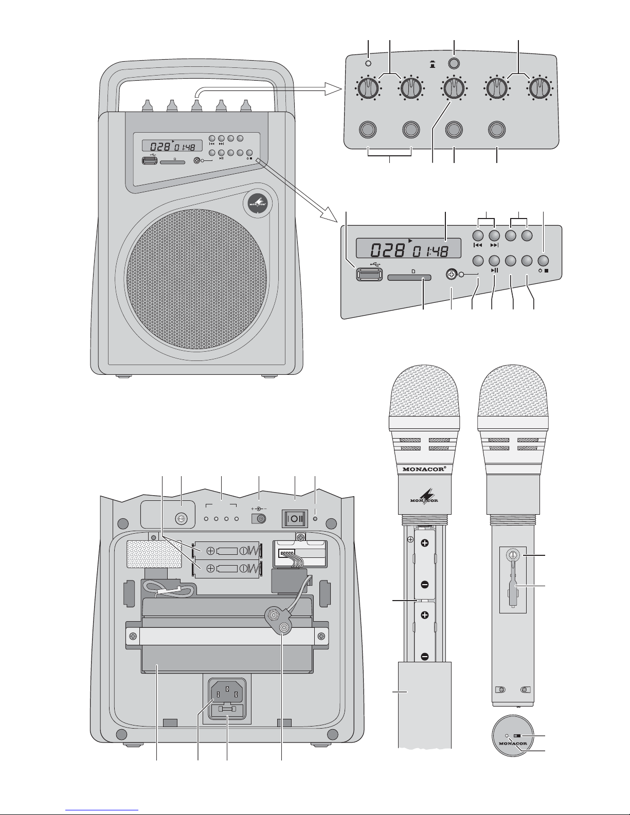
Auf der ausklappbaren Seite 3 finden Sie alle
beschriebenen Bedienelemente und An schlüsse.
1 Übersicht der Bedienelemente
und Anschlüsse
1.1 Ober- und Vorderseite der Aktivbox
1 Empfangsanzeige RF ON; leuchtet, wenn das
Funkmikrofon eingeschaltet und auf den Übertragungskanal der Aktivbox eingestellt ist.
2 Lautstärkeregler MIC 1/ W MIC und MIC 2 für an
den Buchsen MIC 1 und MIC 2 (5) angeschlossene Mikrofone
Der linke Regler MIC 1/ WMIC dient auch zur
Lautstärkeeinstellung für das Funkmikrofon.
3 Taste VOICE PRIORITY für die Übersprech-
funktion:
Ist die Taste gedrückt, werden während einer
Durchsage über das Funkmikrofon oder über
ein an der Buchse MIC 1 (5) angeschlossenes
Mikrofon die Signale des MP3-Spielers und die
Eingangssignale der Buchse AUX (7) ausgeblendet.
4 Höhenregler TREBLE und Tiefenregler BASS
5 Buchsen MIC 1 und MIC 2 (6,3-mm-Klinke) zum
Anschluss von Mikrofonen
6 Lautstärkeregler AUX für ein an der Buchse
AUX (7) angeschlossenes Gerät
7 Eingangsbuchse AUX (6,3-mm-Klinke) zum An -
schluss eines Gerätes mit Line-Pegel-Ausgang
(z. B. CD-Spieler, Kassettenrekorder)
8 Ausgangsbuchse REC OUT (6,3-mm-Klinke)
zum Anschluss eines Aufnahmegerätes oder
eines weiteren Verstärkers
9 USB-Buchse zum Einstecken eines USB-Sticks
10 Display
11 Tasten zum Anwählen des vorherigen
bzw. nächsten Titels. Zum Anwählen des vorherigen bzw. nächsten Ordners die Taste so lange
gedrückt halten, bis die gewünschte Ordnernummer angezeigt wird (F . .).
12 Tasten VOL+ und VOL-für die Lautstärke des
MP3-Spielers
13 Taste zum Ein- und Ausschalten des MP3-
Spielers (die Taste gedrückt halten, bis das Display aufleuchtet bzw. erlischt) und zum Beenden des Abspielens oder einer Aufnahme (die
Taste kurz drücken)
14 Steckplatz für eine SD/ MMC-Speicherkarte
15 Regler LEVEL für die Aufnahmelautstärke
Zum Einstellen den Schlüssel (33) des Funk -
mikrofons zu Hilfe nehmen. Die Anzeige PEAK
neben dem Regler dient zur Kontrolle und darf
bei der höchsten Lautstärke nur kurz aufleuchten.
16 Taste REC für die Aufnahmefunktion (Kap. 5.1)
17 Taste zum Wechseln zwischen Wiedergabe
und Pause
18 Taste RPT zum Wählen einer Wiederholfunk-
tion und zum Abspielen in zufälliger Folge
Grundeinstellung, Anzeige REP
ständige Wiederholung aller Titel
1. Tastendruck, Anzeige REP
Wiederholung des laufenden Titels
2. Tastendruck, keine Anzeige REP
keine Wiederholfunktion
3. Tastendruck, Anzeige REP
Abspielen der Titel in zufälliger Folge
19 Taste SD / USB zum Umschalten zwischen USB-
Stick und SD/ MMC-Karte
1.2 Rückseite der Aktivbox
(Abdeckplatte abgenommen)
20 Ladefach für zwei Akkus der Größe Mignon (AA)
21 Drehschalter RF1 CH SEL zum Einstellen des
Empfangskanals für den Betrieb mit dem Funkmikrofon [Zum Drehen den Einstellschlüssel
(33) des Funkmikrofons zu Hilfe nehmen.]
22 Ladeanzeigen
AA SIZE
für Akkus der Größe Mignon (AA) im Fach
(20), linke Anzeige für den unteren Akku
9 V BLOCK
für einen 9-V-Blockakku, der mit den Druckknopfkontakten (29) verbunden ist
12 V
für den eingebauten 12-V-Akku (26)
23 Kleinspannungsbuchse (Mittelkontakt = Plus-
pol) für den Anschluss einer externen Gleichspannungsversorgung (12 – 15 V), z. B. Autobatterie
Es wird ein Kleinspannungsstecker mit den
Maßen 5,5 / 2,1 mm (Außen- / Innendurchmesser) benötigt.
24 Ein- und Ausschalter POWER
linke Position I
Nur das Ladeteil zum Aufladen der Akkus ist
eingeschaltet.
mittlere Position
Das Gerät ist komplett ausgeschaltet.
rechte Position II
Das Gerät ist eingeschaltet. Der eingebaute
12-V-Akku (26) wird beim Betrieb mit Netzspannung mit einem geringen Strom geladen.
1
ALL
Page 5
D
A
CH
5
25 Betriebsanzeige ON; leuchtet, wenn der Schal-
ter POWER (24) in der Position II steht.
26 12-V-Akku für einen netzunabhängigen Betrieb
27 Netzbuchse zum Anschluss an eine Steckdose
(230 V~ / 50Hz) über das beiliegende Netzkabel
28 Netzsicherung; eine durchgebrannte Sicherung
nur durch eine gleichen Typs ersetzen
29 Druckknopfkontakte
Zum Aufladen kann hier ein 9-V-Blockakku an geschlossen werden.
1.3 Funkmikrofon
30 Batteriefach für zwei Batterien oder Akkus der
Größe Mignon (AA)
31 Schraubhülse
Nach dem Abschrauben sind das Batteriefach
(30) und der Kanalschalter (32) zugängig.
32 Kanalschalter
Zum Drehen den Einstellschlüssel (33) verwenden.
33 Einstellschlüssel für die Kanalschalter (21, 32)
und den Regler LEVEL (15)
34 Ein- und Ausschalter
35 Anzeige BATT für den Ladezustand der Batte-
rien /Akkus
Beim Ein- und Ausschalten leuchtet die Anzeige
kurz auf. Leuchtet sie im Betrieb auf, sind die
Batterien fast verbraucht.
2 Hinweise für den
sicheren Gebrauch
Die Geräte (Aktivbox und Funkmikrofon) entsprechen allen relevanten Richtlinien der EU und sind
deshalb mit gekennzeichnet.
G
Schützen Sie die Geräte vor Tropf- und Spritzwasser, hoher Luftfeuchtigkeit und Hitze (zulässiger Einsatztemperaturbereich 0 – 40 °C).
G
Stellen Sie keine mit Flüssigkeit gefüllten Gefäße,
z. B. Trinkgläser, auf die Aktivbox.
G
Nehmen Sie die am Netz angeschlossene Aktivbox nicht in Betrieb und ziehen Sie sofort den
Netzstecker aus der Steckdose, wenn:
1. sichtbare Schäden an der Aktivbox oder am
Netzkabel vorhanden sind,
2. nach einem Sturz oder Ähnlichem der Verdacht auf einen Defekt besteht.
3. Funktionsstörungen auftreten.
Lassen Sie das Gerät in jedem Fall in einer
Fachwerkstatt reparieren.
G
Ziehen Sie den Netzstecker nie am Kabel aus
der Steckdose, fassen Sie immer am Stecker an.
G
Verwenden Sie für die Reinigung nur ein trockenes, weiches Tuch, niemals Chemikalien oder
Wasser.
G
Werden die Geräte zweckentfremdet, nicht richtig angeschlossen, falsch bedient oder nicht
fachgerecht repariert, kann keine Haftung für
daraus resultierende Sach- oder Personenschäden und keine Garantie für die Geräte übernommen werden. Ebenso kann keine Haftung für
durch Fehlbedienung oder durch einen Defekt
entstandene Datenverluste und deren Folgeschäden übernommen werden.
3 Anwendungsmöglichkeiten
Das transportable Verstärkersystem TXA-380USB
besteht aus einem Funkmikrofon und einer Aktivbox mit MP3-Spieler und Mikrofon-Empfangsteil.
Die Funkübertragung erfolgt im Frequenzbereich
863 – 865 MHz. Die Aktivbox kann wahlweise mit
230-V-Netzspannung, mit dem internen 12-V-Akku
oder mit einer extern zugeführten Gleichspannung
von 12 – 15 V (z.B. von einer Autobatterie) betrieben werden. Das System eignet sich somit optimal
für den Einsatz an wechselnden Standorten, z. B.
für Vorträge oder verschiedene Veranstaltungen.
Die Aktivbox hat zwei Eingänge für kabelgebundene Mikrofone, einen Eingang für ein Audiogerät
mit Line-Ausgangspegel (z. B. Kassettenrekorder,
tragbarer CD-Spieler) und einen Ausgang zum An schluss eines Aufnahmegerätes oder eines weiteren Verstärkers. Über das integrierte Ladeteil lassen sich der eingebaute 12-V-Akku, Akkus für das
Funkmikrofon und zusätzlich ein 9-V-Blockakku
aufladen.
Sollen die Geräte endgültig aus dem
Betrieb genommen werden, übergeben
Sie sie zur umweltgerechten Entsorgung
einem örtlichen Recyclingbetrieb.
Verbrauchte Batterien und defekte Akkus dürfen
nicht in den Hausmüll geworfen werden. Geben
Sie sie zur umweltgerechten Entsorgung nur in
den Sondermüll (z. B. Sammelbehälter bei Ihrem
Einzelhändler).
WARNUNG Die Aktivbox wird mit lebensgefähr-
lich hoher Netzspannung (230 V~)
versorgt. Nehmen Sie deshalb niemals selbst Eingriffe an diesem
Gerät vor. Durch unsachgemäßes
Vorgehen besteht die Gefahr eines
elektrischen Schlages.
Page 6

6
D
A
CH
3.1 Konformität und Zulassung
Hiermit erklärt MONACOR INTERNATIONAL, dass
sich das Verstärkersystem TXA-380USB in Übereinstimmung mit den grundlegenden Anforderungen und den übrigen einschlägigen Bestimmungen
der Richtlinie 1999/ 5 / EG befindet. Die Konformitätserklärung kann bei MONACOR INTERNATIONAL angefordert werden.
Das System ist für den Betrieb in den EU- und
EFTA-Staaten allgemein zugelassen und anmelde-
und gebührenfrei.
4 Inbetriebnahme
4.1 Aufstellung
Die Aktivbox kann frei aufgestellt oder über die
Gewindebuchse auf der Unterseite auf ein Stativ
mit M8-Gewinde montiert werden.
4.2 Stromversorgung der Aktivbox
Die Aktivbox kann wahlweise mit 230-V-Netz span nung, mit dem internen 12-V-Akku oder mit einer
extern zugeführten Gleichspannung von 12 – 15V
(z. B. von einer Autobatterie) betrieben werden.
4.2.1 Netzbetrieb
Das beiliegende Netzkabel zuerst in die Netzbuchse (27) und dann in eine Steckdose (230 V~ /
50 Hz) stecken.
4.2.2 Akkubetrieb/ Akkus aufladen
Für einen netzunabhängigen Betrieb ist ein 12-VAkku (26) eingebaut. Mit ihm ist eine Betriebsdauer
von ca. 3 Stunden möglich (abhängig von der eingestellten Lautstärke).
Wenn der Akku fast entladen ist, schaltet sich die
Aktivbox zum Schutz des Akkus ab. Zum Aufladen
des Akkus die Aktivbox an eine Netzsteckdose an schließen (Kap. 4.2.1) und den Schalter POWER
(24) in die linke Position I stellen. Die Ladeanzeige
12 V (22) leuchtet. Erlischt sie, ist der Akku voll ge laden.
Gleichzeitig können auch ein oder zwei Akkus
der Größe Mignon (AA), z. B. für das Funkmikrofon,
und ein 9-V-Blockakku aufgeladen werden:
1) Die Abdeckplatte der Geräterückseite abnehmen.
2) Mignon-Akkus in das Ladefach (20), mit den
Plus- und Minuskontakten wie im Fach angege-
ben, einsetzen und / oder
einen 9-V-Blockakku auf die Druckknopfkon-
takte (29) stecken und in das zugehörige Lade-
fach schieben.
3) Die Aktivbox mit der Abdeckplatte wieder schließen.
4) Während des Aufladens leuchten die zugehörigen Anzeigen (22):
AA SIZE für die Mignon-Akkus im Fach (20); die
linke Anzeige für den unteren Akku
9 V BLOCK für den 9-V-Blockakku
5) Erlischt eine Anzeige, ist der zugehörige Akku
aufgeladen und kann entnommen werden.
Tipps für eine lange Lebensdauer des eingebauten 12-V-Akkus:
– Vor der ersten Inbetriebnahme den Akku voll auf-
laden.
– Einen entladenen Akku möglichst bald wieder
voll aufladen.
– Wird die Aktivbox längere Zeit nicht benutzt,
sollte der Akku alle 2– 3 Monate voll aufgeladen
werden.
4.2.3 Externe Gleichspannungsquelle
Reicht die Betriebsdauer des internen Akkus nicht
aus, kann ein netzunabhängiger Betrieb auch mit
Hilfe einer externen Gleichspannungsquelle von
12 – 15 V erfolgen, z. B. durch eine 12-V-Auto batterie. Für den Anschluss der Stromversorgung
an die Kleinspannungsbuchse (23) auf der Geräterückseite wird ein Stecker mit den Maßen
5,5/ 2,1 mm (Außen- / Innendurchmesser) benötigt.
Dabei unbedingt auf die richtige Polung achten:
Den Pluspol an den Innenkontakt des Steckers
anlegen.
Beim Anschluss einer Gleichspannungsquelle
ist der interne Akku außer Betrieb. Soll der Akku
durch die Spannungsquelle aufgeladen werden,
wird eine Spannung von 15 V benötigt. Bei diesem Ladevorgang leuchtet die Anzeige 12V (22)
jedoch nicht.
4.3 Stromversorgung des Funkmikrofons
1) Die Schraubhülse (31) abschrauben.
2) Zwei Batterien oder Akkus der Größe Mignon
(AA) in das Batteriefach (30) einlegen. Dabei auf
die richtige Lage der Plus- und Minuskontakte
achten, siehe Abb. 3.
Bei längerem Nichtgebrauch die Batterien
herausnehmen, damit das Mikrofon bei einem
eventuellen Auslaufen der Batterien nicht be schädigt wird.
3) Nach dem Einstellen des Übertragungskanals
(siehe Kap. 5, Bedienschritt 3b) die Schraubhülse wieder auf das Mikrofon schrauben.
Page 7
7
D
A
CH
4.4 Audioanschlüsse
1) Soll zusätzlich zum Funkmikrofon ein kabelgebundenes Mikrofon verwendet werden, dieses
an die Buchse MIC 2 (5) anschließen.
2) Es kann auch ein zweites kabelgebundenes
Mikrofon eingesetzt werden, wenn das Funk mikrofon nicht benutzt wird. Das zweite Mikrofon
an die Buchse MIC 1 (5) anschließen.
Hinweis: Das Funkmikrofon und ein an der Buchse
MIC 1 angeschlossenes Mikrofon können nur dann
gleichzeitig verwendet werden, wenn deren Lautstärke
nicht getrennt eingestellt werden muss. Für beide
Mikrofone ist der Regler MIC 1 / W MIC (2) zuständig.
3) Ein Audiogerät mit Line-Ausgangspegel (z. B.
Kassettenrekorder, Radiorekorder, tragbarer
CD-Spieler) kann an die Buchse AUX (7) ange schlos sen werden.
Hinweis: Bei einem Stereo-Ausgang einen Mono-Stereo-Adapter verwenden, anderenfalls wird nur der linke
Stereo-Kanal wiedergegeben.
4) Über den Ausgang REC OUT (8) kann das
Audiosignal an ein Tonaufnahmegerät oder an
einen weiteren Verstärker weitergeleitet werden.
Die 6,3-mm-Mono-Klinkenbuchse REC OUT mit
dem Line-Eingang des nachfolgenden Gerätes
verbinden.
5 Bedienung
1) Vor dem Einschalten der Aktivbox die Lautstärkeregler (2 und 6) auf Minimum stellen.
2) Zum Einschalten der Aktivbox den Schalter
POWER (24) in die rechte Position II stellen. Die
rote Betriebsanzeige ON (25) leuchtet.
Hinweise
Leuchtet die Anzeige ON nicht beim Betrieb mit dem
eingebauten Akku, den Akku aufladen (Kapitel 4.2.2).
Ist die Aktivbox an einer Steckdose angeschlossen und
eingeschaltet, wird der eingebaute Akku mit einem ge ringen Strom geladen (Erhaltungsladung).
3) Für den Betrieb mit dem Funkmikrofon den
Übertragungskanal einstellen:
a) Das Funkmikrofon noch ausgeschaltet lassen
und erst mit dem Kanalschalter RF1 CH SEL
(21) an der Aktivbox den Kanal wählen. Zum
Drehen kann der Einstellschlüssel (33) des
Mikrofons verwendet werden. Leuchtet nach
der Kanalwahl die grüne Anzeige RF ON (1),
werden Störsignale oder Signale anderer
Funksender empfangen. In diesem Fall einen
anderen Kanal einstellen.
b) Am Funkmikrofon mit dem Einstellschlüssel
den Kanalschalter (32) auf den gleichen
Kanal drehen, der an der Aktivbox eingestellt
ist.
4) Alle verwendeten Tonquellen einschalten. Zum
Einschalten des Funkmikrofons den Schalter
(34) in die Position ON schieben. Die Anzeige
BATT (35) leuchtet kurz rot auf. Leuchtet sie im
Betrieb permanent, sind die eingesetzten Batterien fast verbraucht. Nach dem Einschalten des
Funkmikrofons leuchtet die grüne Anzei ge RF
ON (1) an der Aktivbox und signalisiert damit,
dass ein Funksignal empfangen wird.
5) Die Signale der Tonquellen mit den entsprechenden Lautstärkereglern mischen oder nach
Bedarf ein- und ausblenden:
Regler MIC 1/ W MIC (2):
für das Funkmikrofon und ein an der Buchse
MIC 1 (5) angeschlossenes Mikrofon
Regler MIC 2 (2):
für ein an der Buchse MIC 2 (5) angeschlossenes Mikrofon
Regler AUX (3):
für ein an der Buchse AUX (7) angeschlossenes Gerät
Hinweis: Tritt beim Mikrofonbetrieb ein Rückkopplungspfeifen auf, den Abstand zwischen der Aktivbox
und dem Mikrofon vergrößern und / oder den Lautstärkeregler des zugehörigen Mikrofons entsprechend
zurückdrehen.
6) Mit den Klangreglern (4) – Tiefenregler BASS,
Höhenregler TREBLE – das gewünschte Klangbild einstellen.
7) Bei schlechtem oder gestörtem Empfang des
Funkmikrofons überprüfen, ob:
– auf einem anderen Übertragungskanal der
Empfang besser ist.
Hinweis: Bei dem Funkmikrofon hat eine Änderung
der Kanaleinstellung während des Be triebs keine
Auswirkung. Deshalb nach jedem Kanalwechsel
das Mikrofon kurz ausschalten und dann wieder einschalten.
– die Batterien bzw. Akkus des Mikrofons ver-
braucht sind.
– der Abstand zwischen Funkmikrofon und
Aktivbox zu groß ist oder sich Hindernisse in
VORSICHT Stellen Sie die Lautstärke der Aktiv-
box nie sehr hoch ein. Hohe Lautstärken können auf Dauer das Gehör
schädigen! Das Ohr gewöhnt sich an
sie und empfindet sie nach einiger
Zeit als nicht mehr so hoch. Darum
eine hohe Lautstärke nach der Ge wöhnung nicht weiter erhöhen.
Page 8

8
D
A
CH
der Übertragungsstrecke befinden, die das
Funk signal abschirmen können.
8) Während einer Durchsage über das Funkmikrofon oder über ein an der Buchse MIC 1 (5) angeschlossenes Mikrofon können die Signale des
MP3-Spielers und die Eingangssignale der
Buchse AUX (7) automatisch ausgeblendet werden, damit die Durchsage verständlich ist. Dazu
mit der Taste VOICE PRIORITY (3) die Übersprechfunktion einschalten.
9) Nach dem Betrieb die Aktivbox mit dem Schalter
POWER (24) ausschalten (mittlere Position )
und das Funkmikrofon mit dem Schalter (34)
[Position OFF ].
5.1 MP3-Spieler
1) Wenn die Aktivbox eingeschaltet ist, den MP3Spieler zusätzlich einschalten: Die Taste
(13) so lange gedrückt halten, bis das Display
(10) aufleuchtet. (Zum Ausschalten die Taste so
lange gedrückt halten, bis das Display erlischt.)
Ist ein USB-Stick oder eine SD / MMC-Karte
eingesteckt, startet nach dem Einlesevorgang
der erste Titel, anderenfalls zeigt das Display
an.
2) Zum Abspielen von Audiodateien auf einem
USB-Stick diesen in den USB-Anschluss (9) stecken und zum Abspielen von Audiodateien auf
einer SD/ MMC-Karte (bis 32 GB) diese in den
Schlitz SD (14) stecken. Dabei muss die abgeschrägte Ecke der Karte nach rechts und zum
Gerät zeigen. Soll die Karte wieder entnommen
werden, sie etwas hineindrücken, sodass sie
ausrastet.
Nach dem Einlesevorgang startet der erste
Titel und das Display zeigt die Ordner- und Titelnummer wechselweise an. Die Ordnernummer
ist durch ein F markiert (F für Folder = engl. Ordner). Zusätzlich wird die bereits gespielte Zeit
eines Titels angezeigt (Min. : Sek.).
3) Der MP3-Spieler wird mit den Tasten (11 – 13,
16 – 19) rechts neben dem Display bedient:
Zum Anwählen des vorherigen bzw.
nächsten Titels. Zum Anwählen des
vorherigen bzw. nächsten Ordners die
Taste so lange gedrückt halten, bis die
gewünschte Ordnernummer angezeigt
wird (F . .).
VOL Zum Einstellen der Lautstärke des
MP3-Spielers
REC Für MP3-Tonaufnahmen
Die Taste drücken, nach kurzer Zeit
zeigt das Display an. Mit dem
Regler LEVEL (15) die Aufnahme aussteuern. Dazu den Einstellschlüssel
(33) zu Hilfe nehmen. Die Anzeige
PEAK neben dem Regler dient zur
Kontrolle und darf bei der höchsten
Lautstärke nur kurz aufleuchten.
Hinweis: Die Lautstärke der Aufnahme wird
auch durch die eingestellte Lautstärke für
die Aktivbox bestimmt.
Die Taste REC erneut drücken. Die
Anzeige blinkt kurz, danach startet die Aufnahme und die Zeitanzeige
im Display läuft. Zum Beenden der Aufnahme die Taste drücken.
Die Aufnahmen werden im Ordner
RECORD gespeichert, der mit
angezeigt wird (Folder record). Zum
Abspielen der Aufnahmen diesen Ordner mit den Tasten anwählen.
Zum Umschalten zwischen Wiedergabe
(Anzeige ) und Pause (Anzeige )
RPT Zum Umschalten zwischen:
ständige Wiederholung aller Titel
Anzeige REP (Grundeinstellung)
Wiederholung des laufenden Titels
Anzeige REP
keine Wiederholfunktion
keine Anzeige REP
Abspielen der Titel in zufälliger Folge
Anzeige REP
SD / USB Zum Umschalten zwischen USB-Stick
und SD/ MMC-Karte
Zum Beenden des Abspielens oder
einer Aufnahme (die Taste kurz drücken) und zum Ein- und Ausschalten
des MP3-Spielers (die Taste gedrückt
halten, bis das Display aufleuchtet
bzw. erlischt)
1
ALL
Page 9

9
D
A
CH
6 Technische Daten
Verstärkerleistung
bei Netzbetrieb: . . . 20 W
MAX, 15 WRMS
bei 12-V-Betrieb: . . . 15 WMAX, 12 WRMS
bei Akku-Betrieb: . . 15 WMAX, 12WRMS
Eingänge
Empfindlichkeit / Impedanz /Anschluss
MIC 1, MIC 2: . . . . . 3 mV/1 kΩ
6,3-mm-Klinke, asym.
AUX: . . . . . . . . . . . . 100 mV/ 8,7 kΩ
6,3-mm-Klinke, asym.
Ausgang REC OUT: . . 850 mV
6,3-mm-Klinke, mono
Klangregelung
Tiefen: . . . . . . . . . . . ±6 dB / 80 Hz
Höhen: . . . . . . . . . . ±6 dB / 8 kHz
Stromversorgung
Aktivbox: . . . . . . . . . 230 V~ / 50 Hz / 45VA
oder
12 – 15 V / 3,5 A
oder
eingebauter Blei-Gel-Akku
12 V/ 3,5 Ah
Mikrofon: . . . . . . . . . zwei Batterien oder Akkus
der Größe Mignon (AA)
Ladezeit, Ladestrom
eingebauter Akku: . . ≤ 8 h, 200 – 800 mA
Mignon-Akku: . . . . . ≤ 12 h, 70 — 150 mA
9-V-Akku: . . . . . . . . ≤ 10 h, 5 – 60 mA
Einsatztemperatur: . . . 0 – 40 °C
Abmessungen, Gewicht
Aktivbox: . . . . . . . . . 210 × 285 × 150 mm,
4,5 kg
Mikrofon: . . . . . . . . . ∅ 48 / 35 mm × 230 mm,
160 g
Funkübertragung
Frequenzbereich: . . . . 863 – 865 MHz,
siehe Tabelle unten
Sendeleistung
des Mikrofons: . . . . . . < 10 mW (EIRP)
Reichweite: . . . . . . . . . ca. 25 m
bei Sichtverbindung
Änderungen vorbehalten.
Kanalbelegung
Kanal Frequenz Kanal Frequenz
0 863,05 MHz 5 864,25 MHz
1 863,25 MHz 6 864,55 MHz
2 863,55 MHz 7 864,75 MHz
3 863,75 MHz 8– F 864,95 MHz
4 864,05 MHz
Diese Bedienungsanleitung ist urheberrechtlich für MONACOR®INTERNATIONAL GmbH & Co. KG
geschützt. Eine Reproduktion für eigene kommerzielle Zwecke – auch auszugsweise – ist untersagt.
Page 10

All operating elements and connections de scribed can be found on the fold-out page 3.
1 Operating Elements
and Connections
1.1 Upper side and front side of
the active speaker system
1 Reception LED RF ON; lights up when the
wireless microphone has been switched on and
set to the transmission channel of the active
speaker system
2 Volume controls MIC 1/ W MIC and MIC 2 for
microphones connected to the jacks MIC 1 and
MIC 2 (5)
The left control MIC 1/ W MIC is also used to
adjust the volume of the wireless microphone.
3 Button VOICE PRIORITY for the crosstalk func-
tion:
When the button is pressed, the signals of the
MP3 player and the input signals of the jack
AUX (7) will be faded out when an announcement is made via the wireless microphone or via
a microphone connected to the jack MIC 1 (5).
4 Controls TREBLE and BASS
5 Jacks MIC 1 and MIC 2 (6.3mm jack) to connect
microphones
6 Volume control AUX for a unit connected to the
jack AUX (7)
7 Input jack AUX (6.3 mm jack) to connect a unit
with line level output (e. g. CD player, cassette
recorder)
8 Output jack REC OUT (6.3 mm jack) to connect
a recorder or another amplifier
9 USB port to connect a USB flash drive
10 Display
11 Buttons to select the previous title or
the next title. To select the previous folder or the
next folder, keep the button pressed until the
desired folder number is displayed (F . .).
12 Buttons VOL+ and VOL
-
for the volume of the
MP3 player
13 Button to switch the MP3 player on and off
(keep the button pressed until the display lights
up or is extinguished) and to stop the replay or
a recording (press the button briefly)
14 Slot for an SD / MMC memory card
15 Control LEVEL for the recording volume
To adjust the level, use the key (33) of the wireless microphone. The LED PEAK next to the
control is used as an indication; it may only
briefly light up at the highest volume.
16 Button REC for the recording function
(chapter 5.1)
17 Button to switch between replay and pause
18 Button RPT to select a repeat function and to
replay in a random order
Basic setting, indication REP
continuous repeat of all titles
First press of the button, indication REP
repeat of the current title
Second press of the button, no indication REP
no repeat function
Third press of the button, indication REP
replay of the titles in a random order
19 Button SD / USB to switch between USB flash
drive and SD / MMC card
1.2 Rear side of the active speaker system
(cover plate removed)
20 Charging compartment for two batteries of
size AA
21 Channel selector switch RF1 CH SEL to set the
receiving channel for operation with the wireless
microphone [To turn it, use the adjusting key
(33) of the wireless microphone.]
22 Charge LEDs
AA SIZE
for batteries of size AA in the compartment
(20), left LED for the lower battery
9 V BLOCK
for a 9 V battery connected to the snap-on
contacts (29)
12 V
for the integrated 12 V battery (26)
23 Low-voltage jack (centre contact = positive
pole) to connect an external DC voltage supply
(12 – 15 V), e.g. car battery
A low-voltage plug with the dimensions 5.5 /
2.1 mm (outside / inside diameter) is required.
24 On-off switch POWER
left position I
Only the charger for the batteries is switched
on.
central position
The unit is completely switched off.
right position II
The unit is switched on. When the unit is operated with mains voltage, the integrated 12 V
battery (26) is charged with a low current.
25 Power LED ON; lights up when the switch
POWER (24) is in the position II
1
ALL
10
GB
Page 11
26 12 V battery for mains-independent operation
27 Mains jack for connection to a socket (230 V~ /
50 Hz) via the mains cable provided
28 Mains fuse; replace a blown fuse by one of the
same type only
29 Snap-on contacts
To connect a 9 V battery for recharging.
1.3 Wireless microphone
30 Battery compartment for two batteries or
rechargeable batteries of size AA
31 Screw cap
After unscrewing the cap, the battery compartment (30) and the channel selector switch (32)
are accessible.
32 Channel selector switch
To turn it, use the adjusting key (33).
33 Adjusting key for the channel selector switches
(21, 32) and the control LEVEL (15)
34 On-off switch
35 LED BATT for the battery status
When switching on and off, the LED lights up
briefly. If it lights up during operation, the batteries are almost discharged.
2 Safety Notes
The units (active speaker system and wireless
microphone) correspond to all relevant directives of
the EU and are therefore marked with .
G
Protect the units against dripping water and
splash water, high air humidity and heat (admissible ambient temperature range: 0 – 40 °C).
G
Do not place any vessel filled with liquid on the
active speaker system, e.g. a drinking glass.
G
Do not set the active speaker system into operation when it is connected to the mains and immediately disconnect the mains plug from the
socket
1. if the active speaker system or the mains
cable is visibly damaged,
2. if a defect might have occurred after the unit
was dropped or suffered a similar accident,
3. if malfunctions occur.
In any case the unit must be repaired by skilled
personnel.
G
Never pull the mains cable to disconnect the
mains plug from the socket, always seize the
plug.
G
For cleaning only use a dry, soft cloth; never use
water or chemicals.
G
No guarantee claims for the units and no liability
for any resulting personal damage or material
damage will be accepted if the units are used for
other purposes than originally intended, if they
are not correctly connected or operated, or if
they are not repaired in an expert way. Likewise,
no liability will be accepted for data loss caused
by operating errors or by a defect or for any consequential damage of this data loss.
G
Important for U. K. Customers!
The wires in this mains lead are coloured in ac cord ance with the following code:
green / yellow = earth
blue = neutral
brown = live
As the colours of the wires in the mains lead of
this appliance may not correspond with the
coloured markings identifying the terminals in
your plug, proceed as follows:
1. The wire which is coloured green and yellow
must be connected to the terminal in the plug
which is marked with the letter E or by the
earth symbol , or coloured green or green
and yellow.
2. The wire which is coloured blue must be connected to the terminal which is marked with
the letter N or coloured black.
3. The wire which is coloured brown must be
connected to the terminal which is marked
with the letter L or coloured red.
Warning – This appliance must be earthed.
3 Applications
The portable amplifier system TXA-380USB consists of a wireless microphone and an active
speaker system with MP3 player and microphone
receiver. The wireless transmission is made in the
frequency range 863 to 865 MHz. The active
speaker system can be operated with a 230 V
If the units are to be put out of operation
definitively, take them to a local recycling
plant for a disposal which is not harmful to
the environment.
Never put dead batteries or defective rechargeable batteries in the household waste; always
take them to a special waste disposal, e. g. collection container at your retailer.
WARNING The active speaker system uses
dangerous mains voltage (230 V~).
Leave servicing to skilled personnel
only. Inexpert handling may result in
electric shock.
11
GB
Page 12

mains voltage, with the internal 12 V battery or with
an external 12 – 15 V DC voltage (e.g. from a car
battery). Thus, the system is ideally suited for
mobile applications, e. g. for lectures or various
events.
The active speaker system has two inputs for
cable microphones, an input for an audio unit with
line output level (e. g. cassette recorder, portable
CD player) and an output to connect a recorder or
another amplifier. A built-in charger will recharge
the integrated 12 V battery, batteries for the wireless microphone and also a 9 V battery.
3.1 Conformity and approval
Herewith, MONACOR INTERNATIONAL declare
that the amplifier system TXA-380USB is in accord ance with the basic requirements and the other relevant regulations of the directive 1999 / 5 / EC. The
declaration of conformity is available on re quest
from MONACOR INTERNATIONAL.
The system is licence-free and generally ap proved for operation in EU and EFTA countries.
4 Setting the System into Operation
4.1 Setting up
Place the active speaker system as desired or
mount it onto a stand with M8 thread via the
threaded jack on its lower side.
4.1 Power supply of the
active speaker system
The active speaker system can be operated via the
230 V mains, via the internal 12 V battery or via an
external 12 – 15 V DC voltage (e. g. from a car battery).
4.2.1 Mains operation
Connect the mains cable provided to the mains
jack (27) before connecting it to a mains socket
(230 V~ / 50 Hz).
4.2.2 Battery operation/Recharging the batteries
For mains-independent operation, a 12 V battery
(26) is integrated. It allows an operating time of ap prox. 3 hours (depending on the volume adjusted).
When the battery is almost discharged, the
active speaker system is switched off to protect the
battery. To recharge the battery, connect the active
speaker system to a mains socket (chapter 4.2.1)
and set the switch POWER (24) to the left position I. The charge LED 12 V (22) lights up. When it
is extinguished, the battery is fully recharged.
At the same time, it is possible to recharge one
or two batteries of size AA, e.g. for the wireless
microphone, and a 9 V battery.
1) Remove the cover on the rear side of the unit.
2) Insert batteries of size AA into the charging com-
partment (20) with the positive and negative
poles as indicated in the compartment and / or
connect a 9 V battery to the snap-on contacts
(29) and slide it into the corresponding compart-
ment.
3) Replace the cover to close the active speaker
system.
4) While charging, the corresponding LEDs (22)
light up:
AA SIZE for the batteries of size AA in the com-
partment (20); the left LED for the lower battery
9 V BLOCK for the 9 V battery
5) When one of the LEDs is extinguished, the cor-
responding battery has been fully recharged and
can be removed.
Hints and tips for a long life of the integrated 12 V
battery:
– Fully charge the battery before initial operation.
– Recharge a discharged battery as soon as pos-
sible.
– If the active speaker system is not in use for a
longer period of time, fully recharge the battery
every 2 – 3 months.
4.2.3 External DC voltage source
If the operating time of the internal battery is not
sufficient, a mains-independent operation is possible via an external 12 – 15 V DC voltage source,
e. g. a 12 V car battery. For connecting the power
supply to the low-voltage jack (23) on the rear side
of the unit, a plug with the dimensions 5.5 / 2.1 mm
is required (outside / inside diameter). Always ob serve the correct polarity: The positive pole must
be at the inner contact of the plug.
When a DC voltage source is connected, the
internal battery is out of operation. To recharge the
battery via the voltage source, a voltage of 15 V is
required. However, the LED 12V (22) will not light
up during this charging process.
4.3 Power supply of the
wireless microphone
1) Unscrew the screw cap (31).
2) Insert two (rechargeable) batteries of size AA
into the battery department (30). Observe the
correct position of the positive and negative
poles, see fig. 3.
12
GB
Page 13
If the microphone is not in use for a longer
period of time, remove the batteries to prevent
damage to the microphone caused by battery
leakage.
3) After setting the transmission channel (see
chapter 5, step 3b), replace the screw cap.
4.4 Audio connections
1) When using a cable microphone in addition to
the wireless microphone, connect the cable
microphone to the jack MIC 2 (5).
2) If you do not use the wireless microphone, you
may also use a second cable microphone. Connect the second microphone to the jack MIC 1
(5).
Note: The wireless microphone and a microphone connected to the jack MIC 1 can only be used at the same
time if it is acceptable to adjust them to the same volume. The control MIC 1/ W MIC (2) is used for both
microphones.
3) The jack AUX (7) allows to connect an audio unit
with line output level (e. g. cassette recorder,
radio cassette recorder, portable CD player).
Note: For a stereo output, use a mono stereo adapter;
otherwise only the left stereo channel will be reproduced.
4) Via the output REC OUT (8), the audio signal
can be routed to an audio recorder or another
amplifier. Connect the 6.3mm mono jack REC
OUT to the line input of the subsequent unit.
5 Operation
1) Prior to switching on the active speaker system,
set the volume controls (2 and 6) to minimum.
2) To switch on the active speaker system, set the
switch POWER (24) to the right position II. The
red power LED ON (25) lights up.
Notes
If the LED ON does not light up during operation with the
integrated battery, recharge the battery (chapter 4.2.2).
If the active speaker system is connected to a mains
socket and switched on, the integrated battery will be
recharged with a low current (trickle charge).
3) For operation with the wireless microphone, set
the transmission channel:
a) Before switching on the wireless microphone,
set the channel with the channel selector
switch RF1 CH SEL(21) on the active speaker
system. To turn it, use the adjusting key (33)
of the microphone. If the green LED RF ON
(1) lights up after channel selection, interference signals or signals of other wireless
transmitters are received. In this case, set a
different channel.
b) Use the adjusting key to set the channel
selector switch (32) on the wireless microphone to the channel adjusted on the active
speaker system.
4) Switch on all audio sources used. To switch on
the wireless microphone, set the switch (34) to
ON. The LED BATT (35) briefly shows red. If it
lights continuously during operation, the batteries inserted are almost discharged. After switching on the wireless microphone, the green LED
RF ON (1) on the active speaker system lights
up to indicate reception of a radio signal.
5) Mix the signals of the audio sources with the corresponding volume controls or fade them in and
out as desired:
control MIC 1/ W MIC (2):
for the wireless microphone and a microphone connected to the jack MIC 1 (5)
control MIC 2 (2):
for a microphone connected to the jack MIC 2
(5)
control AUX (3):
for a unit connected to the jack AUX (7)
Note: In case of howling during microphone operation,
increase the distance between the active speaker system and the microphone and / or turn back the volume
control of the corresponding microphone.
6) Adjust the desired sound with the tone controls
(4) [BASS and TREBLE].
7) If the reception of the wireless microphone is
poor or disturbed, please check
– if the reception is better on a different trans-
mission channel.
Note: If you set a different channel during operation,
this change will not affect the wireless microphone.
Therefore, always briefly switch off the microphone
after a different channel has been set, then switch it
on again.
– if the (rechargeable) batteries of the micro-
phone are discharged.
– if the distance between the wireless micro-
phone and the active speaker system is too
long or if there are obstacles in the transmission path which may screen the radio signal.
CAUTION Never adjust the active speaker sys-
tem to a very high volume. Permanent high volumes may damage your
hearing! Your ear will get accustomed to high volumes which do not
seem to be that high after some time.
Therefore, do not further increase a
high volume after getting used to it.
13
GB
Page 14

8) When an announcement is made via the wireless microphone or via a microphone connected
to the jack MIC 1 (5), the signals of the MP3
player and the input signals of the jack AUX (7)
can be faded out automatically in order to make
the announcement intelligible. For this purpose,
activate the crosstalk function with the button
VOICE PRIORITY (3).
9) After operation, switch off the active speaker
system with the switch POWER (24) [central
position ]. Switch off the wireless microphone
with the switch (34) [position OFF].
5.1 MP3 player
1) When the active speaker system is switched on,
also switch on the MP3 player: Keep the button
(13) pressed until the display (10) lights up.
(To switch off, keep the button pressed until the
display is extinguished.)
If a USB flash drive or an SD / MMC card has
been inserted, the first title starts after loading; if
not, the display shows .
2) To replay audio files from a USB flash drive, connect it to the USB port (9). To replay audio files
from an SD / MMC card (up to 32 GB), insert the
card into the slot SD (14), the notched corner to
the right and facing the unit. To remove the card,
slightly push it in to eject the card from the slot.
After loading, the first title starts. The display
alternately shows the folder number and the title
number. The folder number is marked F. In addition, the time already played of the title is indicated (min. : sec.).
3) To operate the MP3 player, use the buttons
(11 – 13, 16 – 19) on the right of the display:
To select the previous title or the next
title. To select the previous folder or the
next folder, keep the button pressed
until the desired folder number is
shown (F . .).
VOL To adjust the volume of the MP3 player
REC For MP3 audio recordings
Press the button. After a while the display shows . Adjust the level of the
recording with the control LEVEL (15).
For this purpose, use the adjusting key
(33). The LED PEAK next to the control
is used as an indication; it may only
briefly light up at the highest volume.
Note: The volume of the recording is also
defined by the volume adjusted for the active
speaker system.
Press the button REC once again. The
indication starts flashing briefly
before the recording starts and the
time indication on the display is activated. To stop the recording, press the
button .
The recordings are stored in the folder
RECORD which is indicated as
(Folder record). To replay the recordings, select this folder with the buttons
.
To switch between replay (indication )
and pause (indication )
RPT To switch between:
continuous repeat of all titles
indication REP (basic setting)
repeat of the current title
indication REP
no repeat function
no indication REP
replay of the titles in a random order
indication REP
SD / USB To switch between USB flash drive and
SD / MMC card
To stop the replay or a recording (press
the button briefly) and to switch the
MP3 player on and off (keep the button
pressed until the display lights up or is
extinguished).
1
ALL
14
GB
Page 15

6 Specifications
Amplifier power
with mains operation: 20 W
MAX, 15 WRMS
with 12 V operation: 15 WMAX, 12 WRMS
with battery
operation: . . . . . . . . 15 W
MAX, 12 WRMS
Inputs
Sensitivity/ Impedance / Connection
MIC 1, MIC 2: . . . . . 3 mV/ 1 kΩ
6.3 mm jack, unbal.
AUX: . . . . . . . . . . . . 100 mV/ 8.7 kΩ
6.3 mm jack, unbal.
Output REC OUT: . . . . 850 mV
6.3 mm jack, mono
Tone control
BASS: . . . . . . . . . . . ±6 dB / 80 Hz
TREBLE: . . . . . . . . . ±6 dB / 8 kHz
Power supply
Active speaker
system: . . . . . . . . . . 230 V~ / 50 Hz / 45 VA
or
12 – 15 V / 3.5 A
or
integrated lead gel battery
12 V/ 3.5 Ah
Microphone: . . . . . . two batteries or rech. bat-
teries of size AA
Charge time, charge current
integrated battery: . . ≤ 8 h, 200 – 800 mA
battery of size AA: . . ≤ 12 h, 70 — 150 mA
9 V battery: . . . . . . . ≤ 10 h, 5– 60 mA
Ambient temperature: . 0 – 40 °C
Dimensions, weight
Active speaker
system: . . . . . . . . . . 210 × 285 × 150 mm,
4.5 kg
Microphone: . . . . . . ∅ 48 / 35 mm × 230 mm,
160 g
Wireless transmission
Frequency range: . . . . 863 – 865 MHz,
see table below
Transmission power of
microphone: . . . . . . . . < 10 mW (EIRP)
Range: . . . . . . . . . . . . approx. 25 m
without any obstacles
Subject to technical modification.
Channel assignment
Channel Frequency Channel Frequency
0 863.05 MHz 5 864.25 MHz
1 863.25 MHz 6 864.55 MHz
2 863.55 MHz 7 864.75 MHz
3 863.75 MHz 8– F 864.95 MHz
4 864.05 MHz
15
GB
All rights reserved by MONACOR®INTERNATIONAL GmbH & Co. KG. No part of this instruction manual
may be reproduced in any form or by any means for any commercial use.
Page 16

Vous trouverez sur la page 3, dépliable, les éléments et branchements décrits.
1 Eléments et branchements
1.1 Face supérieure et
face avant de lʼenceinte active
1 LED témoin de réception RF ON ; brille lorsque
le microphone sans fil est allumé et réglé sur le
canal de transmission de lʼenceinte active
2 Réglage de volume MIC 1/ W MIC et MIC 2 pour
les microphones reliés aux prises MIC 1 et
MIC 2 (5)
Le réglage gauche MIC 1/ W MIC sert également
de réglage de volume pour le micro sans fil.
3 Touche VOICE PRIORITY pour la fonction dia-
phonie :
Si la touche est enfoncée, les signaux du lecteur
MP3 et les signaux dʼentrée de la prise AUX (7)
sont coupés pendant une annonce via le micro
sans fil ou via un micro relié à la prise MIC 1 (5).
4 Réglage des aigus TREBLE et réglage des
graves BASS
5 Prises MIC 1 et MIC 2 (jack 6,35) pour brancher
des microphones
6 Réglage de volume AUX pour un appareil bran-
ché à la prise AUX (7)
7 Prise dʼentrée AUX (jack 6,35) pour brancher un
appareil avec sortie niveau ligne (par exemple
lecteur CD, magnétophone)
8 Prise de sortie REC OUT (jack 6,35) pour bran-
cher un enregistreur ou un second amplificateur
9 Port USB pour insérer une clé USB
10 Affichage
11 Touches pour sélectionner le titre pré-
cédent ou suivant. Pour sélectionner le répertoire précédent ou suivant, maintenez la touche
enfoncée jusquʼà ce que le numéro voulu du
répertoire soit affiché (F . .).
12 Touches VOL+ et VOL
-
pour le volume du lec-
teur MP3
13 Touche pour allumer et éteindre le lecteur
MP3 (maintenez la touche enfoncée jusquʼà ce
que lʼaffiche brille ou sʼéteigne) et pour arrêter la
lecture ou un enregistrement (appuyez brièvement sur la touche)
14 Fente pour insérer une carte mémoire SD / MMC
15 Réglage LEVEL pour le volume dʼenregistre-
ment
Pour effectuer le réglage, utilisez la clé (33) du
micro sans fil. La LED PEAK à côté du réglage
sert de contrôle et ne doit briller que brièvement
pour le volume le plus élevé.
16 Touche REC pour la fonction enregistrement
(chapitre 5.1)
17 Touche pour commuter entre lecture et pause
18 Touche RPT pour sélectionner la fonction répé-
tition et effectuer une lecture en ordre aléatoire
réglage de base, affichage REP
répétition continue de tous les titres
1. pression, affichage REP
répétition du titre en cours
2. pression, pas dʼaffichage REP
aucune fonction répétition
3. pression, affichage REP
lecture des titres en ordre aléatoire
19 Touche SD /USB pour commuter entre la clé
USB et la carte SD / MMC
1.2 Face arrière de lʼenceinte active
(plaque retirée)
20 Compartiment de charge pour deux accumula-
teurs de type R6
21 Sélecteur rotatif RF1 CH SEL pour régler le
canal de réception pour un fonctionnement
avec le micro sans fil [Pour tourner le sélecteur,
utilisez la clé (33) du micro sans fil.]
22 Témoins de charge
AA SIZE
pour accumulateurs de type R6 placés dans
le compartiment (20), LED gauche pour lʼaccumulateur inférieur
9 V BLOCK
pour un accu 9 V, relié aux contacts à pression (29)
12 V
pour lʼaccumulateur 12 V intégré (26)
23 Prise basse tension (contact médian = pôle
plus) pour brancher une tension dʼalimentation
externe (12 – 15 V), p.ex. batterie de voiture
Une fiche basse tension de dimensions 5,5/
2,1 mm (diamètre extérieur / intérieur) est nécessaire.
24 Interrupteur marche / arrêt POWER
position gauche I
Seul le chargeur pour charger les accumulateurs est allumé.
position médiane
Lʼappareil est complètement éteint.
position droite II
Lʼappareil est allumé. Lʼaccumulateur 12 V
intégré (26) est chargé avec une faible cou-
1
ALL
16
F
B
CH
Page 17

rant pendant un fonctionnement sur tension
secteur.
25 Témoin de fonctionnement ON : brille lorsque
lʼinterrupteur POWER (24) est sur la position II
26 Accumulateur 12 V pour un fonctionnement in -
dépendant du secteur
27 Prise pour brancher le cordon livré à une prise
secteur 230 V~ / 50 Hz
28 Fusible secteur : tout fusible fondu doit impéra-
tivement être remplacé par un fusible de même
type
29 Contacts à pression
On peut brancher ici un accu 9 V pour charger.
1.3 Microphone sans fil
30 Compartiment batterie pour deux batteries ou
accumulateurs de type R6
31 Capot à visser
Une fois le capot dévissé, le compartiment batterie (30) et le sélecteur de canaux (32) sont
accessibles.
32 Sélecteur de canaux
Pour tourner le sélecteur, utilisez la clé (33).
33 Clé de réglage pour les sélecteurs de canaux
(21, 32) et le réglage LEVEL (15)
34 Interrupteur marche / arrêt
35 LED BATT pour lʼétat de charge des batteries /
accus
La LED brille brièvement lors de la marche /
arrêt. Si elle brille pendant le fonctionnement,
les batteries sont presque mortes.
2 Conseils dʼutilisation
et de sécurité
Les appareils (enceinte active et micro sans fil)
répondent à toutes les directives nécessaires de
lʼUnion européenne et portent donc le symbole .
G
Protégez les appareils de tout type de projections dʼeau, des éclaboussures, dʼune humidité
de lʼair élevée et de la chaleur (plage de température de fonctionnement autorisée : 0 – 40 °C).
G
En aucun cas, vous ne devez poser dʼobjet contenant du liquide ou un verre sur lʼenceinte active.
G
Ne faites pas fonctionner lʼenceinte active ou dé branchez-la immédiatement du secteur lorsque :
1. des dommages visibles apparaissent sur lʼenceinte active ou sur le cordon secteur,
2. après une chute ou un cas similaire, vous
avez un doute sur lʼétat de lʼappareil,
3. des défaillances apparaissent.
Dans tous les cas, les dommages doivent être
réparés par un technicien spécialisé.
G
Ne débranchez jamais lʼappareil en tirant sur le
cordon secteur, tenez-le toujours par la fiche.
G
Pour les nettoyer, utilisez uniquement un chiffon
sec et doux, en aucun cas, de produits chimiques ou dʼeau.
G
Nous déclinons toute responsabilité en cas de
dommages matériels ou corporels consécutifs si
les appareils sont utilisés dans un but autre que
celui pour lequel ils ont été conçus, sʼils ne sont
pas correctement branchés ou utilisés ou sʼils ne
sont pas réparés par une personne habilitée ; en
outre, la garantie deviendrait caduque. De même,
nous ne saurions être tenus responsables en cas
de pertes de données et de leurs conséquences
dues à une mauvaise utilisation ou un défaut.
3 Possibilités dʼutilisation
Le système amplifié portable TXA-380USB se
compose dʼun microphone sans fil et dʼune
enceinte active avec lecteur MP3 et dʼune unité
récepteur micro. La transmission radio sʼeffectue
dans la plage 863 – 865 MHz. Lʼenceinte active
peut, au choix, fonctionner via une tension secteur
230 V, via lʼaccumulateur interne 12 V ou via une
tension continue externe 12 – 15 V (par exemple
batterie de voiture). Le système est idéal pour une
utilisation mobile sur des lieux différents p. ex. pour
des présentations ou manifestations diverses.
Lʼenceinte active dispose de deux entrées pour
microphones filaires, dʼune entrée pour un appareil
audio avec niveau de sortie ligne (p. ex. magnétophone, lecteur CD portable) et dʼune sortie pour
brancher un enregistreur ou un second amplificateur. Via le chargeur intégré, on peut charger lʼaccumulateur 12 V intégré, des accumulateurs pour
le microphone sans fil et en plus un accu 9 V.
Lorsque les appareils sont définitivement
retirés du service, vous devez les déposer
dans une usine de recyclage adaptée pour
contribuer à leur élimination non polluante.
Ne jetez pas les batteries usagées ou accumulateurs défectueux dans la poubelle domestique,
déposez-les dans un container spécifique ou
ramenez-les à votre revendeur.
AVERTISSEMENT Lʼenceinte active est alimentée
par une tension dangereuse
(230 V~). Ne touchez pas lʼintérieur de lʼappareil car en cas de
mauvaise manipulation, vous
pourriez subir une décharge
électrique.
17
F
B
CH
Page 18

3.1 Conformité et autorisation
Par la présente, MONACOR INTERNATIONAL
déclare que le système amplifié TXA-380USB se
trouve en conformité avec les exigences fondamentales et les réglementations inhérentes à la
directive 1999 / 5 / CE. La déclaration de conformité
peut être demandée auprès de MONACOR
INTERNATIONAL.
Le système est autorisé dans les pays de
lʼUnion européenne et de lʼA.E.L.E. sans déclara-
tion ni frais.
4 Fonctionnement
4.1 Positionnement
Lʼenceinte active peut être posée librement ou
montée sur un pied doté dʼun filetage M8 grâce au
filetage située sur la face inférieure.
4.2 Alimentation de lʼenceinte active
Lʼenceinte active peut fonctionner au choix avec
une tension secteur 230 V, via lʼaccumulateur 12 V
interne ou via une tension continue externe de
12 – 15 V (par exemple dʼune batterie de voiture).
4.2.1 Fonctionnement secteur
Reliez le cordon secteur livré à la prise (27) et lʼautre extrémité à une prise secteur 230 V~ / 50 Hz.
4.2.2 Fonctionnement sur accumulateur /
charge des accumulateurs
Pour un fonctionnement indépendant du secteur,
un accumulateur 12 V (26) est intégré. La durée de
fonctionnement avec cet accumulateur est de
3 heures environ (en fonction du volume réglé).
Lorsque lʼaccumulateur est presque vide, lʼenceinte active sʼéteint pour protéger lʼaccumulateur.
Pour le charger, reliez lʼenceinte active à une prise
secteur (chapitre 4.2.1) et mettez lʼinterrupteur
POWER (24) sur la position gauche I. Le témoin de
charge 12 V (22) brille. Sʼil sʼéteint, lʼaccumulateur
est complètement chargé.
Simultanément, on peut charger un ou deux
accumulateurs de type R6, par exemple pour le
micro sans fil et un accu 9 V :
1) Retirez la plaque sur la face arrière de lʼappareil.
2) Insérez des accumulateurs R6 dans le compar-
timent de charge (20), en positionnant les
contacts plus et moins comme indiqué dans le
compartiment et / ou
reliez un accu 9 V aux contacts à pression et
poussez-le dans le compartiment de charge cor-
respondant.
3) Refermez lʼenceinte active en replaçant la
plaque.
4) Pendant la charge, les LEDs correspondantes
(22) brillent :
AA SIZE pour les accumulateurs R6 placés dans
le compartiment (20) : la LED gauche pour lʼaccumulateur inférieur
9 V BLOCK pour un accumulateur 9 V
5) Si une LED sʼéteint, lʼaccumulateur correspondant est chargé et peut être retiré.
Conseils pour une longue durée de vie de lʼaccumulateur 12 V intégré :
– Avant la première mise en service, chargez com-
plètement lʼaccumulateur.
– Rechargez au plus vite un accumulateur dé -
chargé.
– En cas de non utilisation prolongée de lʼenceinte
active, il convient de charger complètement lʼaccumulateur tous les 2 à 3 mois.
4.2.3 Source de tension continue externe
Si la durée de fonctionnement de lʼaccumulateur
interne ne suffit pas, un fonctionnement indépendant du secteur via une source de tension continue
externe de 12 à 15 V, par exemple une batterie de
voiture 12 V, est possible. Pour brancher lʼalimentation à la prise basse tension (23) sur la face
arrière de lʼappareil, une fiche 5,5 /2,1 mm (diamètre extérieur / intérieur) est nécessaire. Veillez à respecter la polarité : le pôle plus doit être au contact
intérieur de la fiche.
Si vous branchez une source de tension conti-
nue, lʼaccumulateur interne est hors fonction. Si
lʼaccumulateur doit être chargé par la source de
tension, une tension de 15 V est nécessaire. La
LED 12 V (22) ne brille pas pendant ce processus
de charge.
4.3 Alimentation du microphone sans fil
1) Dévissez le capot (31).
2) Insérez deux batteries ou accumulateurs de
type R6 dans le compartiment (30). Veillez au
bon positionnement des contacts plus et moins,
schéma 3.
En cas de non utilisation prolongée, retirez
les batteries, elles pourraient couler et endommager le microphone.
3) Une fois le canal de transmission réglé (chapitre
5, point 3b), revissez le capot sur le microphone.
18
F
B
CH
Page 19

4.4 Branchements audio
1) Si un microphone filaire doit être utilisé en plus
du micro sans fil, reliez-le à la prise MIC 2 (5).
2) Un second micro filaire peut être utilisé si vous
nʼutilisez pas le micro sans fil. Reliez le second
micro à la prise MIC 1 (5).
Conseil : Le micro sans fil et le micro relié à la prise MIC 1
ne peuvent être utilisés simultanément que lorsque le
volume ne doit pas être réglé séparément. Pour les
deux micros, le réglage MIC 1 / W MIC (2) est à utiliser.
3) On peut relier un appareil audio avec niveau de
sortie ligne (par exemple magnétophone, radiocassette, lecteur CD portable) à la prise AUX (7).
Conseil : Pour une sortie stéréo, utilisez un adaptateur
mono / stéréo sinon seul le canal stéréo gauche est restitué.
4) Le signal audio peut être dirigé, via la sortie REC
OUT (8) vers un enregistreur audio ou un autre
amplificateur. Reliez la prise jack 6,35 femelle
mono REC OUT à lʼentrée ligne de lʼappareil suivant.
5 Utilisation
1) Avant dʼallumer lʼenceinte active, mettez les
réglages de volume (2 et 6) sur le minimum.
2) Pour allumer lʼenceinte active, mettre le sélecteur POWER (24) sur la position droite II. La LED
rouge témoin de fonctionnement ON (25) brille.
Conseils
Si la LED ON ne brille pas pour un fonctionnement
avec lʼaccumulateur intégré, chargez lʼaccumulateur
(chapitre 4.2.2).
Si lʼenceinte active est reliée à une prise secteur et est
allumée, lʼaccumulateur intégré est chargé avec un
courant faible (charge de maintien).
3) Pour le fonctionnement avec le micro sans fil,
réglez le canal de transmission :
a) Laissez le micro sans fil éteint et sélectionnez
tout dʼabord le canal sur lʼenceinte active avec
le sélecteur RF1 CH SEL (21). Utilisez la clé
(33) du micro pour tourner le sélecteur. Si la
LED RF ON verte (1) brille une fois le canal
sélectionné, des signaux perturbateurs ou
des signaux dʼautres émetteurs sans fil sont
reçus. Dans ce cas, réglez un autre canal.
b) Sur le micro sans fil, tournez le sélecteur (32)
avec la clé, sur le même canal que celui réglé
sur lʼenceinte active.
4) Allumez toutes les sources audio utilisées. Pour
allumer le micro sans fil, mettez le sélecteur (34)
sur la position ON. Le témoin BATT (35) brille
brièvement en rouge. Sʼil brille en continu pendant le fonctionnement, les batteries insérées
sont presque vides. Une fois le micro sans fil
allumé, la LED verte RF ON (1) brille sur lʼenceinte active, signalant quʼun signal radio est
reçu.
5) Mixez les signaux des sources audio avec les
réglages de volume correspondants et selon les
besoins, faites-les entrer et sortir :
réglage MIC 1 / W MIC (2) :
pour le micro sans fil et un micro relié à la
prise MIC 1 (5)
réglage MIC 2 (2) :
pour un micro relié à la prise MIC 2 (5)
réglage AUX (3) :
pour un appareil relié à la prise AUX (7)
Conseil : En cas de sifflements de larsen lorsque vous
utilisez le micro, augmentez la distance entre lʼenceinte
active et le micro et / ou diminuez le volume du micro
correspondant en tournant le réglage de volume.
6) Avec les réglages de tonalité (4) – réglage
graves BASS, réglage aigus TREBLE – réglez
la tonalité souhaitée.
7) En cas de mauvaise réception ou de réception
perturbée du micro sans fil, vérifiez si :
– la réception est meilleure sur un autre canal
de transmission.
Conseil : Une modification du réglage du canal pendant le fonctionnement avec le micro sans fil nʼa pas
dʼeffet. Après chaque changement de canal, éteignez brièvement le micro sans fil puis rallumez-le.
– les batteries ou accumulateurs du micro sont
vides.
– la distance entre le micro sans fil et lʼenceinte
active est trop importante ou sʼil y a des obstacles dans la voie de transmission pouvant
masquer le signal radio.
8) Pendant une annonce via le micro sans fil ou
via un micro relié à la prise MIC 1 (5), les
signaux du lecteur MP3 et les signaux dʼentrée
de la prise AUX (7) peuvent être automatiquement coupés pour que lʼannonce soit audible.
Activez la fonction de diaphonie avec la touche
VOICE PRIORITY (3).
9) Après le fonctionnement, éteignez lʼenceinte
active avec lʼinterrupteur POWER (24) [position
médiane ] et éteignez le micro sans fil avec
lʼinterrupteur (34) [position OFF ].
ATTENTION Ne réglez jamais le volume de lʼen-
ceinte active trop fort. Un volume
trop élevé peut, à long terme, générer des troubles de lʼaudition.
Lʼoreille sʼhabitue à des volumes élevés et ne les perçoit plus comme tels
au bout dʼun certain temps. Nous
vous conseillons donc de régler le
volume et de ne plus le modifier.
19
F
B
CH
Page 20

5.1 Lecteur MP3
1) Si lʼenceinte active est allumée, allumez en plus
le lecteur MP3 : maintenez la touche (13)
enfoncée jusquʼà ce que lʼaffichage (10) brille.
(Pour éteindre, maintenez la touche enfoncée
jusquʼà ce que lʼaffichage sʼéteigne).
Si une clé USB ou une carte SD / MMC est
insérée, le premier titre démarre après le processus de reconnaissance, sinon lʼaffichage
indique .
2) Pour lire des fichiers audio sur une clé USB,
mettez-la dans le port USB (9) et pour lire des
fichiers audio dʼune carte SD / MMC (jusquʼà
32 GO), mettez la carte dans la fente SD (14). Le
coin oblique de la carte doit être vers la droite et
dirigé vers lʻappareil. Pour retirer la carte, enfoncez-la légèrement pour quʼelle se désenclenche.
Une fois le processus de reconnaissance
terminé, le premier titre démarre, lʼaffichage
indique, en alternance, le numéro du répertoire
et du titre. Le numéro du répertoire est repéré
par un F (F pour Folder = répertoire). En plus, la
durée déjà lue dʼun titre est indiquée (min. : sec.).
3) Pour faire fonctionner le lecteur MP3, utilisez les
touches (11 à 13, 16 à 19), à droite de lʼaffichage :
pour sélectionner le titre précédent ou
le titre suivant. Pour sélectionner le
répertoire précédent ou suivant, maintenez la touche enfoncée jusquʼà ce
que le numéro souhaité du répertoire
soit affiche (F . .).
VOL pour régler le volume du lecteur MP3
REC pour des enregistrements audio MP3
Appuyez sur la touche, peu de temps
après, lʼaffichage indique . Avec le
réglage LEVEL (15) contrôlez lʼenre-
gistrement. Utilisez la clé (33). La LED
PEAK à côté du réglage sert de contrôleur et ne doit briller que brièvement
pour des volumes élevés.
Conseil : Le volume de lʼenregistrement est
déterminé par le volume réglé pour lʼenceinte active.
Appuyez une nouvelle fois sur la
touche REC, lʼaffichage clignote
brièvement, lʼenregistrement démarre
ensuite, lʼindication de durée démarre
sur lʼaffichage. Pour arrêter lʼenregistrement, appuyez sur la touche .
Les enregistrements sont mémorisés
dans le répertoire RECORD, repéré
par (Folder record). Pour lire ces
enregistrements, sélectionnez ce ré pertoire avec les touches .
pour commuter entre lecture (affichage
) et pause (affichage )
RPT pour commuter entre :
répétition continue de tous les titres,
affichage REP (réglage de base)
répétition du titre en cours,
affichage REP
aucune fonction répétition,
pas dʼaffichage REP
lecture des titres en ordre aléatoire,
affichage REP
SD / USB pour commuter entre clé USB et carte
SD / MMC
pour quitter le mode de lecture ou un
enregistrement (appuyez brièvement
sur la touche) et pour allumer et éteindre le lecteur MP3 (maintenez la
touche enfoncée jusquʼà ce que lʼaffichage brille ou sʼéteigne)
1
ALL
20
F
B
CH
Page 21

6 Caractéristiques techniques
Puissance amplificateur
Mode secteur : . . . . 20 W
MAX, 15 WRMS
Mode 12 V : . . . . . . . 15 WMAX, 12WRMS
Mode accu : . . . . . . 15 WMAX, 12WRMS
Entrées
Sensibilité / Impédance / Branchement
MIC 1, MIC 2 : . . . . . 3 mV/1kΩ
jack 6,35, asym.
AUX : . . . . . . . . . . . 100 mV/ 8,7 kΩ
jack 6,35, asym.
Sortie REC OUT : . . . . 850 mV
jack 6,35, mono
Réglage de tonalité
Graves : . . . . . . . . . ±6 dB / 80 Hz
Aigus : . . . . . . . . . . . ±6 dB / 8 kHz
Alimentation
Enceinte active : . . . 230 V~ / 50 Hz / 45 VA
ou
12 – 15 V / 3,5 A
ou
accumulateur plomb / gel
intégré 12 V/ 3,5 Ah
Microphone : . . . . . . 2 batteries ou accus de
type R6
Durée de charge, courant de charge
Accumulateur
intégré : . . . . . . . . . . ≤ 8 h, 200 – 800 mA
Accu R6 : . . . . . . . . ≤ 12 h, 70—150 mA
Accu 9 V : . . . . . . . . ≤ 10 h, 5– 60 mA
Température fonc. : . . 0 – 40 °C
Dimensions, poids
Enceinte active : . . . 210 × 285 × 150 mm,
4,5 kg
Microphone : . . . . . . ∅ 48 / 35 mm × 230 mm,
160 g
Transmission sans fil
Bande passante : . . . . 863 – 865 MHz,
voir tableau ci-dessous
Puissance émission
du micro : . . . . . . . . . . < 10 mW (EIRP)
Portée : . . . . . . . . . . . . 25 m env.
sans obstacle
Tout droit de modification réservé.
Configuration des canaux
canal fréquence canal fréquence
0 863,05 MHz 5 864,25 MHz
1 863,25 MHz 6 864,55 MHz
2 863,55 MHz 7 864,75 MHz
3 863,75 MHz 8– F 864,95 MHz
4 864,05 MHz
21
F
B
CH
Notice dʼutilisation protégée par le copyright de MONACOR®INTERNATIONAL GmbH & Co. KG. Toute
reproduction même partielle à des fins commerciales est interdite.
Page 22

A pagina 3, se aperta completamente, vedrete
tutti gli elementi di comando e i collegamenti
descritti.
1 Elementi di comando
e collegamenti
1.1 Lato superiore e anteriore della
cassa attiva
1 Spia di ricezione RF ON; è accesa se il radio -
microfono à acceso e impostato per il canale di
trasmissione della cassa attiva.
2 Regolatori volume MIC 1/ W MIC e MIC 2 per i
microfoni collegati alle prese MIC 1 e MIC 2 (5)
Il regolatore di sinistra MIC 1/ W MIC serve anche
per la regolazione volume del radiomicrofono.
3 Tasto VOICE PRIORITY per la funzione di dia-
fonia:
Se il tasto è premuto, durante un avviso tramite
il radiomicrofono o tramite un microfono collegato alla presa MIC 1 (5), i segnali del lettore
MP3 e i segnali dʼingresso della presa AUX (7)
vengono disattivati.
4 Regolatori alti TREBLE e bassi BASS
5 Prese MIC 1 e MIC 2 (jack 6,3 mm) per il colle-
gamento dei microfoni
6 Regolatore volume AUX per un apparecchio
collegato alla presa AUX (7)
7 Presa dʼingresso AUX (jack 6,3 mm) per il colle-
gamento di un apparecchio con uscita Line
(p. es. lettore CD, registratore a cassette)
8 Presa dʼuscita REC OUT (jack 6,3 mm) per il
collegamento di un registratore o di un ulteriore
amplificatore
9 Presa USB per inserire una chiavetta USB
10 Display
11 Tasti per scegliere il titolo precedente o
successivo. Per scegliere la cartella precedente
o successiva, tener premuto il tasto finché è
visualizzato il numero richiesto della cartella
(F . .).
12 Tasti VOL+ e VOL
-
per il volume di un lettore
MP3
13 Tasto per accendere e spegnere il lettore
MP3 (tener premuto il tasto finché il display
sʻillumina o si spegne) e per terminare la riproduzione o la registrazione (premere brevemente il tasto)
14 Slot per una scheda di memoria SD / MMC
15 Regolatore LEVEL per il volume della registra-
zione
Per lʼimpostazione servirsi della chiave (33) del
radiomicrofono. La spia PEAK di fianco al regolatore serve per un controllo e deve illuminarsi
solo brevemente con il volume massimo.
16 Tasto REC per la funzione di registrazione
(Cap. 5.1)
17 Tasto per cambiare fra riproduzione e pausa
18 Tasto RPT per scegliere una funzione di ripeti-
zione e per la riproduzione in ordine casuale
Impostazione base, indicazione REP
ripetizione continua di tutti i titoli
1. pressione del tasto, indicazione REP
ripetizione del titolo corrente
2. pressione del tasto, nessuna indicazione REP
nessuna funzione di ripetizione
3. pressione del tasto, indicazione REP
riproduzione dei titoli in ordine casuale
19 Tasto SD / USB per cambiare fra chiavetta USB
e scheda SD / MMC
1.2 Lato posteriore della cassa attiva
(piastra di copertura tolta)
20 Vano di ricarica per due batterie del tipo stilo
(AA)
21 Selettore RF1 CH SEL per impostare il canale di
ricezione per il funzionamento con il radiomicrofono [per girarlo servirsi della chiave di regolazione (33) del radiomicrofono.]
22 Spia di ricarica
AA SIZE
per batterie del tipo stilo (AA) nel vano (20), spia
a sinistra per la batteria in basso
9 V BLOCK
per una batteria transistor di 9 V, collegata
con i contatti a pressione (29)
12 V
per la batteria integrata di 12 V (26)
23 Prese per alimentazione DC (contatto centrale =
polo positivo) per il collegamento di unʼalimentazione esterna di tensione continua (12 – 15 V),
p. es. batteria di automobili.
È richiesto uno spinotto per alimentazione DC
delle dimensioni 5,5 / 2,1 mm (diametro esterno /
interno).
24 Interruttore on / off POWER
posizione a sinistra I
È acceso solo il caricatore per le batterie.
posizione centrale
Lʼapparecchio è spento completamente.
posizione a destra II
Lʼapparecchio è acceso. La batteria ricaricabile di 12 V (26) integrata viene ricaricata con
1
ALL
22
I
Page 23

una corrente bassa durante il funzionamento
con tensione di rete.
25 Spia di funzionamento ON; è accesa quando
lʼinterruttore POWER (24) si trova in posizione II.
26 Batteria ricaricabile di 12 V per il funzionamento
indipendente dalla rete
27 Presa per il collegamento con una presa di rete
(230 V~ / 50 Hz) tramite il cavo in dotazione
28 Fusibile di rete; sostituire un fusibile difettoso
solo con uno dello stesso tipo
29 Contatti a pressione
Per la ricarica si può collegare qui una batteria
transistor di 9 V.
1.3 Radiomicrofono
30 Vano batterie per due batterie (ricaricabili o non)
del tipo stilo (AA)
31 Manicotto a vite
Svitarlo per accedere al vano batterie (30) e al
selettore dei canali (32).
32 Selettore canali
Per girarlo servirsi della chiave (33).
33 Chiave di regolazione per i selettori canali (21,
32) e per il regolatore LEVEL (15)
34 Interruttore on / off
35 Spia BATT per lo stato di carica delle batterie
Durante lʼaccensione e lo spegnimento, la spia
si accende brevemente. Se si accende durante
il funzionamento significa che le batterie sono
quasi scariche.
2 Avvertenze di sicurezza
Gli apparecchi (cassa attiva e radiomicrofono)
sono conformi a tutte le direttive rilevanti dellʼUE e
pertanto portano la sigla .
G
Proteggere gli apparecchi dallʼacqua gocciolante
e dagli spruzzi dʼacqua, da alta umidità dellʼaria
e dal calore (temperatura dʼimpiego ammessa
fra 0 e 40 °C).
G
Non depositare sulla cassa attiva dei contenitori
riempiti di liquidi, p. es. bicchieri.
G
Non mettere in funzione la cassa attiva collegata
con la rete e staccare subito la spina rete se:
1. la cassa attiva o il cavo rete presentano dei
danni visibili;
2. dopo una caduta o dopo eventi simili sussiste
il sospetto di un difetto;
3. gli apparecchi non funzionano correttamente.
Per la riparazione rivolgersi sempre ad unʼofficina competente.
G
Staccare il cavo rete afferrando la spina, senza
tirare il cavo.
G
Per la pulizia usare solo un panno morbido,
asciutto; non impiegare in nessun caso prodotti
chimici o acqua.
G
Nel caso dʼuso improprio, di collegamenti sbagliati, dʼimpiego scorretto o di riparazione non a
regola dʼarte degli apparecchi, non si assume
nessuna responsabilità per eventuali danni consequenziali a persone o a cose e non si assume
nessuna garanzia per lʼapparecchio. Nello
stesso modo non si assume nessuna responsabilità per la perdita di dati e per i relativi danni
consequenziali causati da impiego sbagliato o
da un difetto degli apparecchi.
3 Possibilità dʼimpiego
Il sistema trasportabile dʼamplificazione TXA380USB è composto da un radiomicrofono e da
una cassa attiva con lettore MP3 e unità di ricezione del microfono. La trasmissione via radio
avviene nelle frequenze 863 – 865MHz. La cassa
attiva può funzionare a scelta con la tensione di
rete 230 V, con la batteria ricaricabile interna di 12 V
oppure con una tensione continua esterna di
12 – 15V (p.es. dalla batteria di un automobile).
Pertanto, il sistema è adatto in modo ottimale per
lʼimpiego in luoghi differenti, p. es. per conferenze o
manifestazioni varie.
La cassa attiva dispone di due ingressi per
microfoni collegati via cavo, di un ingresso per un
apparecchio audio con uscita Line (p. es. registratore a cassette, lettore CD portatile) e di unʼuscita
per il collegamento di un registratore o di un amplificatore ulteriore. Per mezzo del caricatore integrato si possono ricaricare la batteria integrada di
12 V, le batterie per il radiomicrofono e in più una
batteria transistor di 9 V.
Se si desidera eliminare gli apparecchi
definitivamente, consegnarli per lo smaltimento ad unʼistituzione locale per il riciclaggio.
Non gettare le batterie scariche o difettose nelle
immondizie di casa bensì negli appositi contenitori (p. es. presso il vostro rivenditore).
AVVERTIMENTO La cassa attiva è alimentata con
pericolosa tensione di rete
(230 V~). Non intervenire mai
personalmente al suo interno. La
manipolazione scorretta può provocare delle scariche elettriche
pericolose.
23
I
Page 24

3.1 Conformità e omologazione
La MONACOR INTERNATIONAL dichiara che il
sistema dʼamplificazione TXA-380USB è conforme
agli requisiti di base e alle rimanenti disposizioni in
materia della direttiva 1999 / 5 / CE. La dichiarazione
di conformità può essere richiesta alla MONACOR
INTERNATIONAL.
Il sistema è omologato per lʼimpiego negli stati
dellʼUE e dellʼEFTA e non richiede né registra-
zione né pagamento di tasse.
4 Messa in funzione
4.1 Collocamento
La cassa attiva può essere collocata liberamente
oppure può essere montata su uno stativo con filettatura M8 per mezzo della boccola filettata che si
trova sul lato inferiore.
4.2 Alimentazione della cassa attiva
La cassa attiva può funzionare a scelta con una
tensione di rete di 230 V, con la batteria ricaricabile
interna di 12 V oppure con una tensione continua
esterna di 12 – 15 V (p.es. della batteria dellʼauto).
4.2.1 Funzionamento a rete
Inserire il cavo rete in dotazione prima nella presa
(27) e quindi in una presa di rete (230 V~ / 50 Hz).
4.2.2 Funzionamento con batterie ricaricabili/
ricaricare le batterie
Per un funzionamento indipendente dalla rete è
integrato una batteria ricaricabile di 12 V (26) che
offre una durata di funzionamento di 3 ore circa
(a seconda del volume impostato).
Quando la batteria e quasi scarica, la cassa si
spegne per proteggere la batteria. Per ricaricare la
batteria collegare la cassa con una presa di rete
(Cap. 4.2.1) e portare lʼinterruttore POWER (24) in
posizione di sinistra I. Si accende la spia di ricarica
12 V (22). Se si spegne, significa che la batteria è
carica.
Nello stesso tempo si possono ricaricare anche
due batterie del tipo stilo (AA), p. es. per il radiomicrofono, e una batteria transistor di 9 V:
1) Staccare la piastra di copertura dal retro della
cassa.
2) Inserire le batterie stilo nel vano di ricarica (20),
con i contatti positivi e negativi come illustrato
nel vano stesso e / o
inserire una batteria transistor di 9V sui contatti
a pressione (29) e spingerla nel vano di ricarica.
3) Richiudere la cassa con la piastra di copertura.
4) Durante la ricarica sono accese le relative spie
(22):
AA SIZE per le batterie stilo nel vano (20); la
spia di sinistra per la batteria in basso
9 V BLOCK per la batteria transistor
5) Se una spia si spegne, la relativa batteria è
carica e può essere tolta.
Consigli per aumentare la durata della batteria
integrata di 12 V:
– Prima della prima messa in funzione ricaricare
completamente la batteria.
– Ricaricare una batteria scarica il più presto pos-
sibile.
– Se la cassa non viene usata per un certo
periodo, la batteria dovrebbe essere ricaricata
completamente ogni 2 / 3 mesi.
4.2.3 Sorgente esterna di tensione continua
Se la durata della batteria interna non è sufficiente,
un funzionamento indipendente dalla rete è possibile anche per mezzo di una sorgente esterna di
tensione continua di 12 – 15 V, p. es. tramite la batteria di unʼautomobile. Per il collegamento dellʼalimentazione con la presa per alimentazione DC
(23) sul lato posteriore dellʼapparecchio è richiesto
uno spinotto delle dimensioni 5,5 / 2,1 mm (diametro
esterno / interno). Fare assolutamente attenzione
alla polarità corretta: il polo positivo sul contatto
interno dello spinotto.
Se è collegata una sorgente esterna di tensione,
la batteria interna è fuori servizio. Se la batteria
deve essere ricaricata dalla sorgente esterna, è
richiesta una tensione di 15 V . In questo caso di
ricarica, la spia 12 V (22) non si accende.
4.3 Alimentazione del radiomicrofono
1) Svitare il manicotto (31).
2) Inserire due batterie, ricaricabili o non, del tipo
stilo (AA) nel vano batterie (30) rispettando la
posizione dei contatti positivi e negativi, vedi
fig. 3.
In caso di mancato uso prolungato conviene
togliere le batterie per non danneggiare il microfono se le batterie dovessero perdere.
3) Dopo lʼimpostazione del canale di trasmissione
(vedi cap. 5, punto 3b) riavvitare il manicotto sul
microfono.
24
I
Page 25

4.4 Collegamenti audio
1) Se oltre al radiomicrofono si deve utilizzare
anche un microfono via cavo, collegarlo con la
presa MIC 2 (5).
2) Si può inserire anche un secondo microfono collegato via cavo, se il radiomicrofono non viene
utilizzato. Collegare il secondo microfono con la
presa MIC 1 (5).
Nota: Il radiomicrofono e un microfono collegato con la
presa MIC 1 possono essere usati contemporaneamente solo se il loro volume non deve essere regolato
separatamente. Entrambi i microfoni sono comandati
dal regolatore MIC 1 / W MIC (2).
3) Un apparecchio audio con uscita Line (p. es. un
registratore a cassette, un radiorecorder, un lettore CD portatile) può essere collegato con la
presa AUX (7).
Nota: Nel caso di unʼuscita stereo, usare un adattatore
mono/stereo; altrimenti sarà riprodotto solo il canale
stereo sinistro.
4) Tramite lʼuscita REC OUT (8), il segnale audio
può essere inoltrato a un registratore audio o a
un amplificatore ulteriore. Collegare la presa
jack mono 6,3 mm REC OUT con lʼingresso Line
dellʼapparecchio a valle.
5 Funzionamento
1) Prima di accendere la cassa attiva portare i
regolatori volume (2 e 6) sul minimo.
2) Per accendere la cassa attiva portare lʼinterruttore POWER (24) in posizione di destra II. Si
accende la spia rossa di funzionamento ON (25).
N.B.
Se la spia ON non si accende durante il funzionamento
con la batteria integrata, occorre ricaricare la batteria
(capitolo 4.2.2).
Se la cassa attiva è collegata con una presa di rete e
se è accesa, la batteria integrata viene ricaricata con
una corrente ridotta (ricarica di mantenimento).
3) Per lʼuso con il radiomicrofono, impostare il
canale di trasmissione:
a) Lasciare spento ancora il radiomicrofono
e dapprima, con il selettore dei canali
RF1 CH SEL (21) scegliere il canale sulla
cassa. Per girare il selettore si può usare la
chiave di regolazione (33) del microfono. Se
dopo la scelta del canale si accende la spia
verde RF ON (1), significa che ci sono delle
interferenze oppure si ricevono di segnali di
altri trasmettitori. In questo caso impostare un
altro canale.
b) Con la chiave di regolazione impostare sul
selettore canali (32) del radiomicrofono lo
stesso canale impostato sulla cassa attiva.
4) Accendere tutte le sorgenti audio utilizzate. Per
accendere il radiomicrofono spostare lʼinterruttore (34) in posizione ON. La spia BATT (35) si
accende brevemente di color rosso. Se rimane
accesa durante il funzionamento, significa che
le batterie inserite sono quasi scariche. Dopo
lʼaccensione del radiomicrofono, la spia verde
RF ON (1) si accende sulla cassa segnalando
che si riceve un segnale radio.
5) Miscelare i segnali delle sorgenti con i relativi
regolatori di volume oppure effettuare dissolvenze in / out secondo necessità:
Regolatore MIC 1/ W MIC (2):
per il radiomicrofono e per un microfono collegato con la presa MIC 1 (5)
Regolatore MIC 2 (2):
per un microfono collegato con la presa
MIC 2 (5)
Regolatore AUX (3):
per un apparecchio collegato con la presa
AUX (7)
Nota: Se durante lʼuso dei microfoni si manifesta un
fischio di feedback ridurre la distanza fra la cassa e il
microfono e/o abbassare il regolatore volume del relativo microfono.
6) Con i regolatori dei toni (4) – bassi BASS, alti
TREBLE – impostare il suono desiderato.
7) In caso di ricezione cattiva o disturbata del
radiomicrofono, controllare se:
– la ricezione è migliore con un altro canale di
trasmissione.
Nota: Con il radiomicrofono, una modifica dellʼimpostazione dei canali non ha effetto durante il
funzionamento. Perciò, dopo ogni cambio canale,
spegnere brevemente il microfono e riaccenderlo
successivamente.
– le batterie del microfono sono scariche.
– la distanza fra radiomicrofono e cassa è
troppo grande oppure se ci sono degli ostacoli sulla linea di trasmissione che possono
schermare il segnale radio.
ATTENZIONE Mai tenere molto alto il volume della
cassa attiva. A lungo andare, il
volume eccessivo può procurare
danni allʼudito! Lʼorecchio si abitua
agli alti volumi e dopo un certo tempo
non se ne rende più conto. Perciò
non aumentare il volume successivamente.
25
I
Page 26

8) Durante un avviso tramite il radiomicrofono o
tramite un microfono collegato con la presa
MIC 1 (5), i segnali del lettore MP3 e i segnali
dʼingresso della presa AUX (7) possono essere
disattivati automaticamente per rendere comprensibile lʼavviso. Per fare ciò attivare la funzione di diafonia con il tasto VOICE PRIORITY
(3).
9) Dopo il funzionamento, spegnere la cassa con
lʼinterruttore POWER (24) [posizione centrale ]
e il radiomicrofono con lʼinterruttore (34) [posizione OFF ].
5.1 Lettore MP3
1) Se la cassa attiva è accesa, accendere anche il
lettore MP3: tener premuto il tasto (13) finche il display (10) sʼillumina. (Per spegnerlo
tener il tasto premuto finché il display si spegne.)
Se è inserita una chiavetta USB o una
scheda SD / MMC, dopo la carica dei dati sʼavvia
automaticamente il primo titolo; altrimenti il
display indica .
2) Per riprodurre dei file audio su una chiavetta
USB, inserire la stessa in una porta USB (9), e
per riprodurre dei file audio su una scheda SD /
MMC (fino a 32 GB) inserire questʼultima nello
slot SD (14). Lʼangolo smussato della scheda
deve essere orientato verso destra e verso lʼapparecchio. Per togliere nuovamente la scheda,
spingerla un poʼ indentro per sbloccarla.
Dopo la carica dei dati, il primo titolo sʼavvia,
e il display indica, uno dopo lʼaltro, il numero
della cartella e del titolo. Il numero della cartella
è contrassegnato da una F (F per folder = ingl.
cartella). Inoltre viene indicato il tempo già passato di un titolo (min. : sec.).
3) I comandi del lettore MP3 si fanno con i tasti
(11 – 13, 16 – 19) a destra del display:
Per scegliere il titolo precedente o successivo. Per scegliere la cartella precedente o successiva tener premuto il
tasto finché viene visualizzato il
numero desiderato della cartella (F . .).
VOL Per impostare il volume del lettore
MP3
REC Per registrazione audio MP3
Premere il tasto, dopo breve tempo il
display indica . Con il regolatore
LEVEL (15) pilotare la registrazione.
Per fare ciò aiutarsi con la chiave di
regolazione (33). La spia PEAK vicino
al regolatore serve come controllo, e
con il volume massimo si deve accendere solo brevemente.
Nota: Il volume della registrazione è determinato anche dal volume impostato per la
cassa attiva.
Premere nuovamente il tasto REC. La
spia lampeggia brevemente,
quindi parte la registrazione e lʼindicazione del tempo inizia a scorrere sul
display. Per terminare la registrazione
premere il tasto .
Le registrazioni vengono memorizzate
nella cartella RECORD, contrassegnata con (Folder record). Per
riprodurre le registrazioni, scegliere
quella cartella con i tasti .
Per cambiare fra riproduzione (indicazione ) e pausa (indicazione )
RPT Per cambiare fra:
ripetizione continua di tutti i titoli
indicazione REP
(impostazione base)
ripetizione del titolo corrente
indicazione REP
nessuna funzione di riproduzione
nessuna indicazione REP
riproduzione dei titoli in ordine casuale
indicazione REP
SD / USB Per cambiare fra chiavetta USB e
scheda SD / MMC
Per terminare la riproduzione o una
registrazione (premere il tasto brevemente) e per accendere e spegnere il
lettore MP3 (tener premuto il tasto, finché il display sʼillumina o si spegne)
1
ALL
26
I
Page 27

6 Dati tecnici
Potenza dellʼamplificatore
con rete: . . . . . . . . . 20 W
MAX, 15 WRMS
con 12 V: . . . . . . . . . 15 WMAX, 12WRMS
con batterie: . . . . . . 15 WMAX, 12 WRM
Ingressi
Sensibilità / impedenza / connessione
MIC 1, MIC 2: . . . . . 3 mV/1kΩ
jack 6,3 mm, sbil.
AUX: . . . . . . . . . . . . 100 mV/ 8,7 kΩ
jack 6,3 mm, sbil.
Uscita REC OUT: . . . . 850 mV
jack 6,3 mm, mono
Regolazione toni
Bassi: . . . . . . . . . . . ±6 dB / 80Hz
Alti: . . . . . . . . . . . . . ±6 dB / 8 kHz
Alimentazione
Cassa attiva: . . . . . . 230 V~ / 50 Hz / 45 VA
oppure
12 – 15 V / 3,5 A
oppure
batteria integrata al
piombo-gel 12 V/ 3,5 Ah
Microfono: . . . . . . . . due batterie ricaricabili o
non del tipo stilo (AA)
Durata, corrente di ricarica
Batteria integrata: . . ≤ 8 h, 200– 800 mA
Batteria stilo: . . . . . . ≤ 12 h, 70 —150mA
Batteria transistor: . ≤ 10 h, 5 – 60 mA
Temperatura
dʼesercizio: . . . . . . . . . 0 – 40 °C
Dimensioni, peso
Cassa attiva: . . . . . . 210 × 285 × 150 mm,
4,5 kg
Microfono: . . . . . . . . ∅ 48 / 35 mm × 230 mm,
160 g
Trasmissione radio
Frequenze: . . . . . . . . . 863 – 865 MHz,
vedi tabella in basso
Potenza di trasmissione
del microfono: . . . . . . . < 10 mW (EIRP)
Portata: . . . . . . . . . . . . ca. 25 m
con vista libera
Con riserva di modifiche tecniche.
Impostazione canali
Canale Frequenza Canale Frequenza
0 863,05 MHz 5 864,25 MHz
1 863,25 MHz 6 864,55 MHz
2 863,55 MHz 7 864,75 MHz
3 863,75 MHz 8– F 864,95 MHz
4 864,05 MHz
27
I
La MONACOR®INTERNATIONAL GmbH & Co. KG si riserva ogni diritto di elaborazione in qualsiasi forma
delle presenti istruzioni per lʼuso. La riproduzione – anche parziale – per propri scopi commerciali è vietata.
Page 28

Op de uitklapbare pagina 3 vindt u een overzicht van alle bedieningselementen en de aansluitingen.
1 Overzicht van de bedienings-
elementen en aansluitingen
1.1 Boven- en voorzijde van de actieve
luidspreker
1 Ontvangst-led RF ON; licht op, als de radiomi-
crofoon ingeschakeld is en op het transmissiekanaal van de actieve luidspreker is ingesteld.
2 Volumeregelaar MIC 1/ W MIC en MIC 2 voor op
de jacks MIC 1 en MIC 2 (5) aangesloten microfoons
De linker regelaar MIC 1/ W MIC dient om het
volume van de radiomicrofoon in te stellen.
3 Toets VOICE PRIORITY voor de overspraak-
functie
Bij ingedrukte toets worden tijdens een aankondiging via de radiomicrofoon of via een op de
jack MIC 1 (5) aangesloten microfoon de signalen van de mp3-speler en de ingangssignalen
van de jack AUX (7) uitgeschakeld.
4 Regelaars voor hoge (TREBLE) en lage tonen
(BASS)
5 Bussen MIC 1 en MIC 2 (6,3 mm-jack) voor aan-
sluiting van microfoons
6 Volumeregelaar AUX voor een op de jack AUX
(7) aangesloten apparaat
7 Ingangsjack AUX (6,3 mm-jack) voor aanslui-
ting van een apparaat met lijnniveau, b.v. een
cd-speler, cassetterecorder)
8 Uitgangsjack REC OUT (6,3 mm-jack) voor het
aansluiten van een opnameapparaat of een bijkomende versterker
9 USB-jack voor het inpluggen van een USB-stick
10 Display
11 Toetsen om de vorige of volgende track
te selecteren. Om de vorige of volgende map
te selecteren, houdt u de toets ingedrukt tot
het gewenste mapnummer wordt weergegeven
(F . .).
12 Toetsen VOL+ en VOL
-
voor het volume van de
mp3-speler
13 Toets voor het in- en uitschakelen van de
mp3-speler (de toets ingedrukt houden tot het
display oplicht of uitgaat) en voor het beëindigen van weergave of opname (kort op de toets
drukken)
14 Slot voor een SD / MMC-geheugenkaart
15 Regelaar LEVEL voor het geluidsvolume van de
opname
Voor het instellen gebruikt u de sleutel (33) van
de radiomicrofoon. De led PEAK naast de regelaar dient als controle en mag bij het maximale
geluidsvolume slechts even oplichten.
16 Toets REC voor de opnamefunctie (hfdst. 5.1)
17 Toets om tussen afspelen en pauze te wisse-
len
18 Toets RPT om een herhalingsfunctie te selecte-
ren en in willekeurige volgorde af te spelen
Basisinstelling, displaybericht REP
continue herhaling van alle tracks
1ste keer drukken, displaybericht REP
herhaling van de geselecteerde track
2de keer drukken, geen displaybericht REP
geen herhalingsfunctie
3de keer drukken, displaybericht REP
de tracks worden in willekeurige volgorde
afgespeeld
19 Toets SD / USB om tussen USB-stick en SD/
MMC-kaart te wisselen
1.2 Achterzijde van de actieve luidspreker
(afdekplaat weggenomen)
20 Laadvak voor twee accuʼs van het mignontype
(AA)
21 Draaischakelaar RF1 CH SEL om het ontvangst-
kanaal voor gebruik met de radiomicrofoon in te
stellen [Gebruik de instelsleutel (33) van de
radiomicrofoon om te draaien.]
22 Ledʼs voor laadstatus
AA SIZE
voor accuʼs van het mignontype (AA) in het
vak (20), linker led voor de onderste accu
9 V BLOCK
voor een 9 V-blokbatterij die met de drukknopcontacten (29) verbonden is
12 V
voor de ingebouwde 12 V-accu (26)
23 Laagspanningsjack (centercontact = positieve
pool) voor het aansluiten van externe gelijkspanningsbron (12 – 15 V), b.v. autobatterij
Hiervoor hebt u een laagspanningsstekker met
de afmetingen 5,5 / 2,1 mm (buiten- / binnendiameter) nodig.
24 POWER-schakelaar
linker stand I
Alleen de laadmodule om de accu op te
laden, is ingeschakeld.
middelste stand
Het apparaat is volledig uitgeschakeld.
1
ALL
28
NL
B
Page 29

rechter stand II
Het apparaat is ingeschakeld. De ingebouwde 12 V-accu (26) wordt tijdens het be drijf op netspanning met een geringe stroom
geladen.
25 POWER-led ON; licht op, als de schakelaar
POWER (24) in de stand II staat.
26 12 V-accu voor een netonafhankelijk bedrijf
27 POWER-jack voor aansluiting op een stopcon-
tact (230 V~ / 50 Hz) via het bijgeleverde net snoer
28 Netzekering; vervang een gesmolten zekering
uitsluitend door een zekering van hetzelfde type
29 Drukknopcontacten
Voor het laden kunt u hier een 9V-blokaccu
aansluiten.
1.3 Radiomicrofoon
30 Batterijvak voor twee batterijen of accuʼs van
het mignontype (AA)
31 Schroefhuls
Na het afschroeven zijn het batterijvak (30) en
de kanaalschakelaar (32) toegankelijk.
32 Kanaalschakelaar
Gebruik de instelsleutel (33) om te draaien.
33 Instelsleutel voor de kanaalschakelaars (21, 32)
en de regelaar LEVEL (15)
34 POWER-schakelaar
35 Led BATT voor de laadtoestand van de batte-
rijen / accuʼs
Bij het in- en uitschakelen licht de led kort op.
Als ze tijdens het bedrijf oplicht, zijn de batterijen bijna leeg.
2 Veiligheidsvoorschriften
De apparaten (actieve luidspreker en radiomicrofoon) zijn in overeenstemming met alle relevante
EU-Richtlijnen en dragen daarom het kenmerk .
G
Vermijd druip- en spatwater, uitzonderlijk warme
plaatsen en plaatsen met een hoge vochtig heid (toegestaan omgevingstemperatuurbereik:
0 – 40 °C).
G
Plaats geen bekers met vloeistof zoals drinkglazen op de actieve luidspreker.
G
Schakel de op het net aangesloten actieve luidspreker niet in en trek onmiddellijk de stekker uit
het stopcontact, wanneer:
1. de actieve luidspreker of het netsnoer zichtbaar beschadigd zijn,
2. er een defect zou kunnen optreden nadat het
apparaat bijvoorbeeld gevallen is.
3. een apparaat slecht functioneert.
Het apparaat moet in elk geval hersteld worden
door een gekwalificeerd vakman.
G
Trek de stekker nooit met het snoer uit het stopcontact, maar met de stekker zelf.
G
Verwijder het stof met een droge, zachte doek.
Gebruik zeker geen chemicaliën of water.
G
In geval van ongeoorloofd of verkeerd gebruik,
verkeerde aansluiting, foutieve bediening of van
herstelling door een niet-gekwalificeerd persoon
vervalt de garantie en de verantwoordelijkheid
voor hieruit resulterende materiële of lichamelijke schade. Zo kunnen wij ook niet aansprakelijkheid worden gesteld voor gegevensverliezen
als gevolg van foutieve bediening of een defect,
noch voor de schade die hieruit volgt.
3 Mogelijke toepassingen
Het transporteerbare versterkersysteem TXA380USB bestaat uit een radiomicrofoon en een
actieve luidspreker met mp3-speler en microfoonontvangstmodule. De radiotransmissie gebeurt in
het frequentiebereik 863 – 865 MHz. De actieve
luidspreker kan naar keuze met 230 V-netspanning, met de interne 12 V-accu of met een extern
gelijkspanning van 12 – 15 V (b.v. van een autobatterij) worden gevoed. Het systeem is bijgevolg optimaal geschikt voor het gebruik aan wisselende
locaties, b.v. voor lezingen of verschillende evenementen.
De actieve luidspreker heeft twee ingangen voor
microfoons met snoer, een ingang voor een audioapparaat met lijnuitgangsniveau (b.v. cassetterecorder, draagbare cd-speler) en een uitgang voor
het aansluiten van een opnameapparaat of een
andere versterker. Via de geïntegreerde laadmodule kunt u de ingebouwde 12 V-accu, de accuʼs
voor de radiomicrofoon en ook nog een 9 V-blokbatterij laden.
Wanneer de apparaten definitief uit bedrijf
worden genomen, bezorg ze dan voor verwerking aan een plaatselijk recyclagebedrijf.
Lege batterijen en defecte accuʼs horen niet in het
huisvuil. Verwijder ze voor een milieuvriendelijke
verwerking uitsluitend als KGA (b.v. de inzamelbox bij de detailhandel).
WAARSCHUWING De netspanning (230 V~) van de
actieve luidspreker is levensgevaarlijk. Open het apparaat
daarom nooit zelf, want door
onzorgvuldige ingrepen loopt u
het risico van elektrische schokken.
29
NL
B
Page 30

3.1 Conformiteit en goedkeuring
Hiermee verklaart MONACOR INTERNATIONAL
dat het versterkersysteem TXA-380USB in overeenstemming is met de basisvereisten en de overige
geldende bepalingen van de richtlijn 1999 / 5 / EG.
De verklaring van overeenstemming kan bij
MONACOR INTERNATIONAL worden aangevraagd.
Het gebruik van de systeem is algemeen toege-
laten in de Lidstaten van de EU en de EFTA, en is
vrij van registratie en van taksen.
4 Ingebruikneming
4.1 Opstelling
De actieve luidspreker kan vrij worden opgesteld of
via de draadbus aan de onderzijde op een statief
met M8-draad worden gemonteerd.
4.2 Voedingsspanning van de actieve
luidspreker
De actieve luidspreker kan naar keuze met 230 Vnetspanning, met de interne 12 V-accu of met een
extern gelijkspanning van 12 – 15 V (b.v. van een
autobatterij) worden gevoed.
4.2.1 Netvoeding
Ten slotte verbindt u het meegeleverde netsnoer
eerst met de POWER-jack (27) en plugt u de stekker ervan in een stopcontact (230 V~ / 50 Hz).
4.2.2 Accubedrijf/ accuʼs laden
Voor een netonafhankelijk bedrijf is er een 12Vaccu ingebouwd. Hiermee is een bedrijfsduur van
ca. 3 uur mogelijk (afhankelijk van het ingestelde
geluidsvolume).
Als de accu bijna leeg is, schakelt de actieve
luidspreker uit om de accu te beschermen. Om de
accu te laden, sluit u de actieve luidspreker aan op
een stopcontact (hoofdstuk 4.2.1) en zet u de schakelaar POWER (24) in de linker stand I. De led voor
laadstatus 12 V (22) licht op. Als ze uitgaat, is de
accu volledig geladen.
Tegelijk kunnen ook een of twee accuʼs van het
mignontype (AA), b.v. voor de radiomicrofoon, en
een 9 V-blokbatterij geladen worden:
1) Neem de afdekplaat van achterzijde van het
apparaat weg.
2) Plaats de mignonaccuʼs in het laadvak (20), met
de positieve en negatieve contacten zoals in het
vak gedrukt, en / of
verbind een 9 V-blokbatterij met de drukknop-
contacten (29) en schuif ze in het bijbehorende
laadvak.
3) Plaats de afdekplaat terug op de actieve luidspreker.
4) Tijdens het laden lichten de overeenkomstige
ledʼs (22) op:
AA SIZE voor de mignonaccuʼs in het vak (20);
de linker led voor de onderste accu
9 V BLOCK voor de 9 V-blockaccu
5) Als er een led uitgaat, dan is de overeenkomstige accu geladen en kunt u deze eruit nemen.
Tips voor een lange levensduur van de ingebouwd
12 V-accu:
– Voor de eerste ingebruikneming laadt u de accu
volledig op.
– Laad een lege accu zo snel mogelijk weer op.
– Als u de actieve luidspreker een langere periode
niet gebruik, moet u de accu om de 2 – 3 maan-
den volledig laden.
4.2.3 Externe gelijkspanningsbron
Als de bedrijfsduur van de interne accu niet volstaat, kunt u het apparaat ook voeden met een
externe gelijkspanningsbron van 12 – 15 V, b.v. een
12 V-autobatterij. Voor aansluiting van de voedingsspanning op de laagspanningsjack (23) aan
de achterzijde van het apparaat hebt u een stekker
nodig met de afmetingen 5,5 / 2,1 mm (buiten- / binnendiameter). Let daarbij op de correcte polariteit:
Verbind de positieve pool met het binnencontact
van de stekker.
Bij aansluiting van een gelijkspanningsbron is
de interne accu buiten bedrijf. Als de accu door de
spanningsbron wordt geladen, is een spanning
nodig van 15 V . Tijdens dit laadproces licht de led
12 V (22) echter niet op.
4.3 Voedingsspanning van
de radiomicrofoon
1) Draai de schroefhuls (31) los.
2) Plaats twee batterijen of accuʼs van het mignon-
type (AA) in het batterijvak (30). Let daarbij op
de correcte positie van de positieve en nega-
tieve contacten, zie figuur 3.
Als de microfoon langere tijd niet wordt
gebruikt, neemt u de batterijen eruit, zodat hij
niet wordt beschadigd bij eventueel uitlopen van
de batterijen.
3) Na het instellen van het transmissiekanaal (zie
hoofdstuk 5, bedieningsstap 3b) draait u de
schroefhuls opnieuw op de microfoon.
30
NL
B
Page 31

4.4 Audio-aansluitingen
1) Als u naast de radiomicrofoon een microfoon
met snoer wilt gebruiken, sluit deze dan aan op
de jack MIC 2 (5).
2) U kunt ook een tweede microfoon met snoer
gebruiken, als u de radiomicrofoon niet gebruikt.
Sluit de tweede microfoon aan op de jack MIC 1
(5).
Opmerking: De radiomicrofoon en een op de jack
MIC 1 aangesloten microfoon kunnen enkel tegelijk
worden gebruikt, als het geluidsvolume ervan niet
afzonderlijk moet worden ingesteld. Voor beide microfoons wordt de regelaar MIC 1 / W MIC (2) gebruikt.
3) U kunt een audioapparaat met lijnuitgangsniveau
(b.v. cassetterecorder, radiorecorder, draagbare
cd-speler) aansluiten op de jack AUX (7) aansluiten.
Opmerking: Gebruik bij een stereo-uitgang een monostereo-adapter, anders wordt alleen het linker stereokanaal weergegeven.
4) Via de uitgang REC OUT (8) kan het audiosignaal naar een geluidsopnameapparaat of een
andere versterker worden doorgestuurd. Verbind de 6,3 mm-monojack REC OUT met de lijningang van het volgende apparaat.
5 Bediening
1) Voor het inschakelen van de actieve luidspreker
zet u de volumeregelaars (2 en 6) in de minimumstand.
2) Om de luidspreker in te schakelen, plaatst u de
schakelaar POWER (24) in de rechter stand II.
De rode POWER-led ON (25) licht op.
Opmerkingen
Als de led ON niet oplicht tijdens het gebruik met ingebouwde accu, moet u de accu laden (hoofdstuk 4.2.2).
Als de actieve luidspreker op een stopcontact aangesloten en ingeschakeld is, wordt de ingebouwde accu
met een kleine hoeveelheid stroom geladen (onderhoudsniveau).
3) Stel voor gebruik met de radiomicrofoon het
transmissiekanaal in:
a) Laat de radiomicrofoon nog uitgeschakeld en
selecteer het kanaal met de kanaalschakelaar RF1 CH SEL (21) op de actieve luidspre-
ker. Om te draaien kunt u de instelsleutel (33)
van de microfoon gebruiken. Als na het selecteren van het kanaal de groene led RF ON (1)
oplicht, worden stoorsignalen of signalen van
andere radiozenders ontvangen. Stel in dit
geval een ander kanaal in.
b) Op de radiomicrofoon draait u kanaalschake-
laar (32) met de instelsleutel naar hetzelfde
kanaal dat op de actieve luidspreker is ingesteld.
4) Schakel de gebruikte geluidsbronnen in. Om de
radiomicrofoon in te schakelen, schuift u de
schakelaar van de (34) in de stand ON. De led
BATT (35) licht kort rood op. Als ze tijdens het
bedrijf permanent oplicht, dan zijn de batterijen
bijna leeg. Na het inschakelen van de radiomicrofoon licht de groene LED RF ON (1) van de
actieve luidspreker op, wat aangeeft dat er een
radiosignaal wordt ontvangen.
5) Meng de signalen van de geluidsbronnen met
de betreffende volumeregelaars mengen of
meng ze volgens behoefte in en uit:
Regelaar MIC 1/ W MIC (2):
voor de radiomicrofoon en een microfoon die
aangesloten is op de jack MIC 1 (5)
Regelaar MIC 2 (2):
voor een microfoon die aangesloten is op de
jack MIC 2 (5)
Regelaar AUX (3):
voor een apparaat dat aangesloten is op de
jack AUX (7)
Opmerking: In geval van een terugkoppelingstoon tijdens het gebruik van de microfoon vergroot u de
afstand tussen de actieve luidspreker en de microfoon
en / of draait u de volumeregelaar van de bijbehorende
microfoon overeenkomstig terug.
6) Met de klankregelaars (4) – regelaar voor lage
(BASS) en hoge (TREBLE) tonen – stelt u de
gewenste klank in.
7) Controleer bij slechte of gestoorde ontvangst
van de radiomicrofoon, of:
– de ontvangst op een ander transmissiekanaal
beter is.
Opmerking: Bij de radiomicrofoon heeft een wijziging van de kanaalinstelling tijdens het gebruik
geen effect. Schakel de microfoon daarom na elke
kanaalwijziging kort uit en daarna opnieuw in.
– de batterijen of accuʼs van de microfoon leeg
zijn.
– de afstand tussen radiomicrofoon en actieve
luidspreker te groot is, of dat er zich hindernissen in de transmissielijn bevinden die het
radiosignaal kunnen tegenhouden.
8) Tijdens een aankondiging via de radiomicrofoon
of via een microfoon die op de jack MIC 1 (5) is
OPGELET Stel het volume op de actieve luid-
spreker nooit zeer hoog in. Langdurige blootstelling aan hoge volumes
kan het gehoor beschadigen! Het
gehoor raakt aangepast aan hoge
volumes die na een tijdje niet meer
zo hoog lijken. Verhoog daarom het
volume niet nog meer, nadat u er
gewoon aan bent geraakt.
31
NL
B
Page 32

aangesloten, kunnen de signalen van de mp3speler en de ingangssignalen van de jack AUX
(7) automatisch worden uitgeschakeld, zodat de
aankondiging verstaanbaar is. Schakel hiervoor
de overspraakfunctie in met de toets VOICE
PRIORITY (3).
9) Na het gebruik schakelt u de actieve luidspreker
uit met de schakelaar POWER (24) [middelste
stand ] en de radiomicrofoon met de schakelaar (34) [stand OFF ].
5.1 Mp3-speler
1) Als de actieve luidspreker ingeschakeld is,
schakelt u bovendien de mp3-speler in: Houd de
toets (13) ingedrukt tot het display (13)
oplicht. (Om uit te schakelen, houdt u de toets
ingedrukt tot het display uitgaat.)
Als u een USB-stick of een SD / MMC-kaart
insteekt, start na het inlezen de eerste track;
anders verschijnt op het display.
2) Om audiobestanden van een USB-stick af te
spelen, steekt u deze in de USB-aansluiting (9),
en om audiobestanden van een SD / MMC-kaart
(tot 32 GB) af te spelen, steekt u deze in de SDsleuf (14). Daarbij moet de afgeschuinde hoek
van de kaart naar rechts en naar het apparaat
zijn gericht. Als u de kaart er weer wilt uitnemen,
drukt u ze iets in, zodat ze ontgrendelt.
Na het inlezen start de eerste track en op het
display verschijnen na elkaar het map- en tracknummer. Het mapnummer is door een F gemarkeerd (F staat voor ʻfolderʼ, in het NL ʻmapʼ).
Bovendien wordt de reeds gespeelde tijd van
een track weergegeven (min. : sec.).
3) De mp3-speler wordt met de toetsen (11– 13,
16 – 19) rechts naast het display bediend:
Om de vorige of volgende track te
selecteren. Om de vorige of volgende
map te selecteren, houdt u de toets
ingedrukt tot het gewenste mapnummer wordt weergegeven (F . .).
VOL Om het geluidsvolume van de mp3-
speler
REC Voor mp3-geluidsopnames
Druk op de toets, na korte tijd geeft het
display aan. Moduleer de opname
met de regelaar LEVEL (15). Gebruik
hiervoor de instelsleutel (33). De led
PEAK naast de regelaar dient als controle en mag bij het maximale geluidsvolume slechts even oplichten.
Opmerking: Het geluidsvolume van de
opname wordt ook door het ingestelde
geluidsvolume voor de actieve luidspreker
bepaald.
Druk nogmaals op de toets REC. De
led knippert kort, daarna start de
opname en loopt de tijdsaanduiding op
het display. Om de opname te beëindigen, drukt u op de toets .
De opnames worden opgeslagen in de
map RECORD die met aangeduid wordt (Folder record). Om de
opnames af te spelen, selecteert u
deze map met de toetsen .
Om te wisselen tussen afspelen (weergave ) en pauze (weergave )
RPT Om te wisselen tussen:
continue herhaling van alle tracks
displaybericht REP (basisinstelling)
herhaling van de geselecteerde track
displaybericht REP
geen herhalingsfunctie
geen displaybericht REP
de tracks worden in willekeurige volgorde afgespeeld
displaybericht REP
SD / USB Om tussen USB-stick en SD / MMC-
kaart te wisselen
Om het afspelen of een opname (kort
op toets drukken) te beëindigen, en om
de mp3-speler in en uit te schakelen
(toets ingedrukt houden tot het display
oplicht of uitgaat).
1
ALL
32
NL
B
Page 33

6 Technische gegevens
Versterkervermogen
bij netbedrijf: . . . . . . 20 W
MAX, 15 WRMS
bij 12 V-bedrijf: . . . . 15 WMAX, 12WRMS
bij accubedrijf: . . . . . 15 WMAX, 12 WRMS
Ingangen
Gevoeligheid / Impedantie /Aansluiting
MIC 1, MIC 2: . . . . . 3 mV/ 1 kΩ
6,3 mm-jack,
ongebalanceerd
AUX: . . . . . . . . . . . . 100 mV/ 8,7 kΩ
6,3 mm-jack,
ongebalanceerd
Uitgang REC OUT: . 850 mV
6,3 mm-jack, mono
Equalizer
Lage tonen: . . . . . . . ±6 dB / 80 Hz
Hoge tonen: . . . . . . ±6 dB / 8 kHz
Voedingsspanning
Actieve luidspreker: 230 V~ / 50 Hz / 45VA
of
12 – 15 V / 3,5 A
of
ingebouwde loodgelaccu
12 V/ 3,5 Ah
Microfoon: . . . . . . . . twee batterijen of accuʼs
van het mignontype (AA)
Laadtijd, laadstroom
ingebouwde accu: . . ≤ 8 h, 200 – 800 mA
Mignonaccu: . . . . . . ≤ 12 h, 70—150mA
9 V-Accu: . . . . . . . . . ≤ 10 h, 5– 60mA
Omgevingstemperatuurbereik: . . . 0 – 40 °C
Afmetingen, gewicht
Actieve luidspreker: 210 × 285 × 150 mm,
4,5 kg
Microfoon: . . . . . . . . ∅ 48 / 35 mm × 230 mm,
160 g
Draadloze transmissie
Frequentiebereik: . . . . 863 – 865 MHz,
zie tabel onderaan
Zendvermogen
van de microfoon: . . . . < 10 mW (EIRP)
Reikwijdte: . . . . . . . . . ca. 25 m
bij visuele verbindingslijn
Wijzigingen voorbehouden.
Kanaalbezetting
Kanaal Frequentie Kanaal Frequentie
0 863,05 MHz 5 864,25 MHz
1 863,25 MHz 6 864,55 MHz
2 863,55 MHz 7 864,75 MHz
3 863,75 MHz 8– F 864,95 MHz
4 864,05 MHz
33
NL
B
Deze gebruiksaanwijzing is door de auteurswet beschermd aigendom van voor MONACOR®INTERNATIONAL GmbH & Co. KG. Een reproductie – ook gedeeltelijk – voor eigen commerciële doeleinden is verboden.
Page 34

Puede encontrar todos los elementos de funcionamiento y las conexiones que se describen
en la página 3 desplegable.
1 Elementos de Funcionamiento
y Conexiones
1.1 Parte superior y
parte frontal del recinto activo
1 LED de recepción RF ON; se ilumina cuando el
micrófono inalámbrico se ha conectado y ajustado en el canal de transmisión del recinto
activo
2 Controles de volumen MIC 1/ W MIC y MIC 2
para micrófonos conectados a las tomas MIC 1
y MIC 2 (5)
El control izquierdo MIC 1/ W MIC también se
utiliza para ajustar el volumen del micrófono
inalámbrico.
3 Botón VOICE PRIORITY para la función cross-
talk:
Cuando se pulsa el botón, las señales del lector MP3 y las señales de entrada de la toma
AUX (7) desaparecen cuando se hace un anuncio a través del micrófono inalámbrico o
mediante un micrófono conectado a la toma
MIC 1 (5).
4 Controles TREBLE y BASS
5 Tomas MIC 1 y MIC 2 (jack 6,3 mm,) para conec-
tar micrófonos
6 Control de volumen AUX para un aparato
conectado a la toma AUX (7)
7 Entrada AUX (jack 6,3 mm) para conectar un
aparato con salida de nivel de línea (p. ej. lector
CD, grabador de cintas)
8 Toma de salida REC OUT (jack 6,3 mm) para
conectar un grabador u otro amplificador
9 Puerto USB para conectar una unidad flash
USB
10 Visualizador
11 Botones para seleccionar la pista ante-
rior o la posterior. Para seleccionar la carpeta
anterior o la posterior, mantenga pulsado el
botón hasta que se visualice el número de carpeta deseado (F . .).
12 Botones VOL+ y VOL
-
para el volumen del lec-
tor MP3
13 Botón para conectar y desconectar el lec-
tor MP3 (mantenga pulsado el botón hasta que
se ilumine o se apague el visualizador) y para
parar la reproducción o una grabación (pulse el
botón brevemente)
14 Ranura para tarjeta de memoria SD / MMC
15 Control LEVEL para el volumen de grabación
Para ajustar el nivel, utilice la llave (33) del
micrófono inalámbrico. El LED PEAK junto al
control se utiliza como indicación; sólo puede
iluminarse brevemente con el volumen más elevado.
16 Botón REC para la función de grabación (apar-
tado 5.1)
17 Botón para conmutar entre reproducción y
pausa
18 Botón RPT para seleccionar una función de
repetición y para reproducir en orden aleatorio
Ajuste básico, indicación REP
Repetición continua de todas las pistas
Primera pulsación del botón, indicación REP
Repetición de la pista actual
Segunda pulsación del botón, sin indicación REP
No hay función de repetición
Tercera pulsación del botón, indicación REP
Reproducción de las pistas en orden aleatorio
19 Botón SD / USB para conmutar entre unidad
flash USB y tarjeta SD / MMC
1.2 Parte posterior del recinto activo
(tapa extraída)
20 Compartimento de carga para dos baterías AA
21 Interruptor selector de canal RF1 CH SEL para
ajustar el canal de recepción para el funcionamiento con el micrófono inalámbrico [Para
girarlo, utilice la llave de ajuste (33) del micrófono inalámbrico.]
22 LEDs de carga
AA SIZE
Para baterías de tipo AA en el compartimento
(20), LED izquierdo para batería baja
9 V BLOCK
Para una batería de 9 V conectada a los contactos a presión (29)
12 V
Para la batería integrada de 12 V (26)
23 Toma de bajo voltaje (contacto central = polo
positivo) para conectar a una alimentación de
voltaje DC externa (12 – 15 V), p.ej. una batería
de coche
Se necesita un conector de bajo voltaje con las
dimensiones 5,5 / 2,1 mm (diámetro exterior /
interior).
24 Interruptor POWER on / off
1
ALL
34
E
Page 35

Posición izquierda I
Sólo está conectado el cargador para las
baterías.
Posición central
El aparato está completamente desconectado.
Posición derecha II
El aparato está conectado. Cuando el aparato funciona con voltaje de corriente, la batería integrada de 12 V (26) se va cargando con
una corriente baja.
25 LED de corriente ON; se ilumina cuando el inter -
ruptor POWER (24) está en la posición II
26 Batería de 12 V para funcionamiento indepen-
diente
27 Toma de corriente para la conexión a un
enchufe (230 V~ / 50 Hz) mediante el cable de
corriente entregado
28 Fusible de corriente; cambie un fusible fundido
sólo por otro del mismo tipo
29 Contactos a presión
Para conectar una batería de 9 V y recargarla.
1.3 Micrófono inalámbrico
30 Compartimento de la batería para dos baterías
o baterías recargables de tipo AA
31 Tuerca
Después de destornillar la tuerca, se puede
acceder al compartimento de la batería (30) y al
interruptor selector de canal (32).
32 Interruptor selector de canal
Para girarlo, utilice la llave de ajustes (33).
33 Llave de ajuste para los interruptores selectores
de canal (21, 32) y para el control LEVEL (15)
34 Interruptor on / off
35 LED BATT para el estado de la batería
Durante la conexión y la desconexión, el LED
se ilumina brevemente. Si se ilumina durante el
funcionamiento, significa que las baterías están
casi descargadas.
2 Notas de Seguridad
Los aparatos (recinto activo y micrófono inalámbrico) cumplen con todas las directivas relevantes
de la UE y por lo tanto están marcados con el símbolo .
G
Proteja los aparatos de goteos y salpicaduras,
elevada humedad del aire y calor (temperatura
ambiente admisible: 0 – 40 ºC).
G
No coloque ningún recipiente con líquido encima
del recinto activo, p.ej. un vaso.
G
No ponga el recinto activo en funcionamiento
cuando está conectado a la corriente y desconecte inmediatamente el enchufe de la toma de
corriente si:
1. El recinto activo o el cable de corriente están
visiblemente dañados.
2. El aparato ha sufrido daños después de una
caída o accidente similar.
3. No funciona correctamente.
Sólo el personal cualificado puede reparar el
aparato bajo cualquier circunstancia.
G
No tire nunca del cable de corriente para desconectarlo de la toma, tire siempre del enchufe.
G
Utilice sólo un paño suave y seco para la limpieza; no utilice nunca ni agua ni productos químicos.
G
No podrá reclamarse garantía o responsabilidad
alguna por cualquier daño personal o material
resultante si los aparatos se utilizan para otros
fines diferentes a los originalmente concebidos,
si no se conectan correctamente, no se utilizan
adecuadamente o no se reparan por expertos.
Del mismo modo, no se aceptará ninguna responsabilidad por la pérdida de datos provocada
por un defecto o por los daños a consecuencia
de esta pérdida de datos.
3 Aplicaciones
El recinto amplificador portátil TXA-380USB está
formado por un micrófono inalámbrico y un recinto
activo con lector MP3 y micrófono receptor. El sistema de transmisión inalámbrico funciona en el
rango de frecuencias 863 – 865 MHz. El recinto
activo se puede utilizar con un voltaje de 230 V, con
la batería interna de 12 V o con un voltaje externo
de 12 – 15 V DC (p.ej. la batería de un coche). Por
lo tanto, el sistema está adecuado especialmente
para aplicaciones móviles, p. ej. para discursos o
varios eventos.
Si va a poner los aparatos fuera de servicio definitivamente, llévelos a la planta de
reciclaje más cercana para que su eliminación no perjudique el medioambiente.
No deposite las baterías gastadas o defectuosas
en el contenedor normal; llévelas a un contenedor
especial, p. ej. al contenedor de su vendedor o a
una compañía de reciclaje.
ADVERTENCIA El recinto activo utiliza un voltaje
peligroso (230 V~). Deje el mantenimiento en manos del personal
cualificado. El manejo inexperto
puede provocar una descarga.
35
E
Page 36

El recinto activo tiene dos entradas para micrófonos con cable, una entrada para un aparato de
audio con salida de nivel de línea (p. ej. grabador
de cintas, lector CD portátil) y una salida para
conectar un grabador u otro amplificador. Un cargador integrado recargará la batería de 12 V integrada, las baterías para el micrófono inalámbrico e
incluso una batería de 9 V.
3.1 Conformidad y aprobación
Por la presente, MONACOR INTERNATIONAL
declara que el amplificador TXA-380USB cumple
con los requisitos básicos y las demás regulaciones relevantes de la directiva 1999 / 5 / EC. La declaración de conformidad está disponible bajo petición
en MONACOR INTERNATIONAL.
El sistema no requiere ninguna licencia y está
aprobado para el funcionamiento en la UE y en los
países de la AELC.
4 Puesta en Marcha del Sistema
4.1 Configuración
Coloque el recinto activo como quiera o móntelo en
un pie con rosca M8 mediante la toma roscada de
su parte inferior.
4.2 Alimentación para el recinto activo
El recinto activo puede funcionar con un voltaje de
230 V, con la batería interna de 12 V o con un voltaje externo de 12 – 15 V DC (p. ej. la batería de un
coche).
4.2.1 Funcionamiento por corriente
Conecte el cable de corriente entregado a la toma
de corriente (27) y luego al enchufe (230 V~ / 50 Hz).
4.2.2 Funcionamiento con batería/
Recarga de las baterías
Batería de 12 V integrada (26) para un funcionamiento independiente. Permite un tiempo de funcionamiento de unas 3 horas (dependiendo del
volumen ajustado).
Cuando la batería está casi descargada, el
recinto activo se desconecta para proteger la batería. Para recargar la batería, conecte el recinto
activo a una toma de corriente (apartado 4.2.1) y
ponga el interruptor POWER (24) en la posición
izquierda I. Se ilumina el LED de carga 12 V (22).
Cuando se apaga, significa que la batería está cargada completamente.
Al mismo tiempo, se pueden recargar una o dos
baterías del tipo AA, p.ej. para el micrófono inalámbrico, y una batería de 9 V.
1) Extraiga la tapa de la parte posterior del apa-
rato.
2) Inserte las baterías del tipo AA en el comparti-
mento de carga (20) con los polos positivo y
negativo como se indica en el compartimento
y/o
conecte una batería de 9 V a los contactos a
presión (29) y colóquela en el compartimento
correspondiente.
3) Coloque de nuevo la tapa para cerrar el recinto
activo.
4) Durante la carga, se iluminan los LEDs corres-
pondientes (22):
AA SIZE para baterías de tipo AA en el compar-
timento (20); LED izquierdo para batería baja
9 V BLOCK para la batería de 9 V
5) Cuando se apaga uno de los LEDs, significa que
la batería correspondiente se ha recargado
completamente y puede extraerse.
Trucos y consejos para alargar la vida de la batería de 12 V integrada:
− Recargue completamente la batería antes del
funcionamiento inicial.
− Recargue una batería descargada en cuanto
sea posible.
− Si no va a utilizar el recinto activo durante mucho
tiempo, recargue completamente la batería cada
2 – 3 meses.
4.2.3 Fuente externa de voltaje DC
Si el tiempo de funcionamiento de la batería interna
no es suficiente, puede funcionar sin batería
mediante una fuente de alimentación externa de
12 – 15 V DC, p. ej. una batería de coche de 12 V.
Para conectar la fuente a la toma de bajo voltaje
(23) de la parte posterior del aparato, se necesita
un conector con las dimensiones 5,5 / 2,1 mm (diámetro exterior / interior). Preste atención siempre a
la polaridad correcta: El polo positivo debe estar en
el contacto interior del conector.
Cuando se conecta una fuente de voltaje DC, la
batería interna no funciona. Para recargar la batería mediante la fuente de voltaje, se necesita un
voltaje de 15 V . Sin embargo, el LED 12 V (22) no
se iluminará durante este proceso de carga.
36
E
Page 37

4.3 Alimentación del micrófono
inalámbrico
1) Desenrosque la tuerca (31).
2) Inserte dos baterías (recargables) del tipo AA en
el compartimento de la batería (30). Preste atención a la posición correcta de los polos positivo
y negativo, ver fig. 3.
Si el micrófono no se va a utilizar durante un
largo periodo de tiempo, quite las baterías para
prevenir daños en el micrófono provocados por
el derrame de una batería.
3) Después de ajustar el canal de transmisión (ver
apartado 5, paso 3b), coloque la tuerca de
nuevo.
4.4 Conexiones de audio
1) Cuando se utiliza un micrófono con cable ade-
más del micrófono inalámbrico, conecte el
micrófono con cable a la toma MIC 2 (5).
2) Si no utiliza el micrófono inalámbrico, también
puede utilizar un segundo micrófono con cable.
Conecte el segundo micrófono a la toma MIC 1
(5).
Nota: El micrófono inalámbrico y un micrófono conectado a la toma MIC 1 sólo se pueden utilizar al mismo
tiempo si no hay problema en ajustarlos al mismo volumen. El control MIC 1/ W MIC (2) se utiliza para ambos
micrófonos.
3) La toma AUX (7) permite conectar un aparato de
audio con nivel de salida de línea (p.ej. grabador
de cintas, radio, lector CD portátil).
Nota: Para una salida estéreo, utilice un adaptador
estéreo mono; de lo contrario sólo se reproducirá el
canal estéreo izquierdo.
4) Mediante la toma REC OUT (8), la señal de
audio se puede direccionar a un grabador de
audio o a otro amplificador. Conecte la toma jack
6,3 mm mono REC OUT a la entrada de línea
del siguiente aparato.
5 Funcionamiento
1) Antes de conectar el recinto activo, ponga los
controles de volumen (2 y 6) al mínimo.
2) Para conectar el recinto activo, ponga el inter ruptor POWER (24) en la posición derecha II. Se
ilumina el LED rojo ON (25).
Notas
Si el LED ON no se ilumina durante el funcionamiento
con la batería integrada, recargue la batería (apartado 4.2.2).
Si el recinto activo está conectado a una toma de
corriente y se enciende, la batería integrada se recargará con una corriente baja (carga de compensación).
3) Para el funcionamiento con el micrófono inalámbrico, ajuste el canal de transmisión:
a) Antes de conectar el micrófono inalámbrico,
ajuste el canal con el interruptor selector de
canal RF 1 CH SEL (21) del recinto activo.
Para girarlo, utilice la llave de ajustes (33) del
micrófono. Si el LED verde RF ON (1) se ilumina después de seleccionar un canal, significa que se reciben interferencias o señales
de otros emisores inalámbricos. En este
caso, ajuste un canal diferente.
b) Utilice la llave de ajustes para poner el inter -
ruptor selector de canal (32) del micrófono
inalámbrico en el canal ajustado del recinto
activo.
4) Conecte todas las fuentes de audio utilizadas.
Para conectar el micrófono inalámbrico, ponga
el interruptor (34) en ON. El LED BATT (35) se
ilumina brevemente en rojo. Si se ilumina continuamente durante el funcionamiento, significa
que las baterías están casi descargadas. Después de conectar el micrófono inalámbrico, el
LED verde RF ON (1) del recinto activo se ilumina para indicar la recepción de una señal de
radio.
5) Mezcle las señales de las fuentes de audio con
los controles de volumen correspondientes o
fúndalos como desee:
Control MIC 1/ W MIC (2):
Para el micrófono inalámbrico y un micrófono
conectado a la toma MIC 1 (5)
Control MIC 2 (2):
Para un micrófono conectado a la toma MIC 2
(5).
Control AUX (3):
Para un aparato conectado a la toma AUX (7)
Nota: Si aparecen pitidos durante el funcionamiento
del micrófono, aumente la distancia entre el recinto
activo y el micrófono y/o baje el control del volumen del
micrófono correspondiente.
PRECAUCIÓN No ajuste nunca el recinto activo en
un volumen muy elevado. Los volúmenes altos permanentes pueden
dañar su oído. Su oído se acostumbrará a los volúmenes altos que no
lo parecen tanto después de un
rato. Por lo tanto, no aumente un
volumen alto después de acostumbrarse a él.
37
E
Page 38

6) Ajuste el sonido deseado con los controles de
tono (4) [BASS y TREBLE].
7) Si la recepción del micrófono inalámbrico es
pobre o con interrupciones, compruebe si:
– La recepción es mejor en un canal de trans-
misión diferente.
Nota: Si ajusta un canal diferente durante el funcionamiento, no afectará al micrófono inalámbrico. Por
lo tanto, desconecte brevemente el micrófono después de ajustar un canal diferente, luego conéctelo
de nuevo.
– Las baterías (recargables) del micrófono
están descargadas.
– La distancia entre el micrófono inalámbrico y
el recinto activo es demasiado grande o si
hay obstáculos en la vía de transmisión que
pueden bloquear la señal de radio.
8) Cuando se hace un anuncio mediante el micrófono inalámbrico o mediante un micrófono
conectado a la toma MIC 1 (5), las señales del
lector MP3 y las señales de entrada de la toma
AUX (7) se pueden desaparecer automáticamente para que se entienda el anuncio. Para
ello, active la función crosstalk con el botón
VOICE PRIORITY (3).
9) Después del funcionamiento, desconecte el
recinto activo con el interruptor POWER (24)
[posición central ]. Desconecte el micrófono
inalámbrico con el interruptor (34) [posición
OFF].
5.1 Lector MP3
1) Cuando se conecta el recinto activo, también
conecta el lector MP3: Mantenga pulsado el
botón (13) hasta que se ilumine el visualizador (10). (Para la desconexión, mantenga pulsado el botón hasta que se apague el visualizador.)
Si se ha insertado una unidad flash USB o
una tarjeta SD / MMC, se iniciará la primera pista
después de la carga, de lo contrario en el visualizador se mostrará .
2) Para reproducir archivos de audio desde una
unidad flash USB, conéctela al puerto USB (9).
Para reproducir archivos de audio desde una
tarjeta SD / MMC (hasta 32 GB), inserte la tarjeta
en la ranura SD (14) con la esquina biselada
hacia la derecha y mirando hacia el aparato.
Para extraer la tarjeta, empújela levemente para
expulsarla de la ranura.
Después de la carga se iniciará la primera
pista. El visualizador muestra alternativamente
el número de carpeta y el número de pista. El
número de carpeta se marca con una F (F para
folder = carpeta en inglés). Además, se indica el
tiempo transcurrido de una pista (min : seg).
3) Para utilizar el lector MP3, utilice los botones
(11 – 13, 16 – 19) a la derecha del visualizador:
Para seleccionar la pista anterior o la
posterior. Para seleccionar la carpeta
anterior o la posterior, mantenga pulsado el botón hasta que se visualice el
número de carpeta deseado (F . .).
VOL Para ajustar el volumen del lector MP3
REC Para grabaciones de audio MP3
Pulse el botón. Al rato, se indicará
en el visualizador. Ajuste el nivel de la
grabación con el control LEVEL (15).
Para ello, utilice la llave a justes (33).
El LED PEAK junto al control se utiliza
como indicación; sólo puede iluminarse brevemente con el volumen más
elevado.
Nota: El volumen de la grabación también
se define mediante el volumen ajustado
para el recinto activo.
Pulse el botón REC una vez más. La
indicación empieza a parpadear
brevemente antes de que empiece la
grabación y se activa la indicación
temporal del visualizador. Para parar la
reproducción, pulse el botón .
Las grabaciones se guardan en la carpeta RECORD indicada como
(Folder record). Para reproducir las
grabaciones, seleccione esta carpeta
con los botones .
Para cambiar entre reproducción (indicación ) y pausa (indicación )
RPT Para cambiar entre:
repetición continua de todas las pistas
indicación REP (ajuste básico)
repetición de la pista actual
indicación REP
sin función de repetición
no hay indicación REP
reproducción de las pistas en orden
aleatorio
indicación REP
SD / USB Para cambiar entre unidad flash USB y
tarjeta SD / MMC
Para parar la reproducción o una gra-
bación (pulse brevemente el botón) y
para conectar y desconectar el lector
MP3 (mantenga pulsado el botón
hasta que se ilumine o se apague el
visualizador)
1
ALL
38
E
Page 39

6 Especificaciones
Potencia de amplificación
Con funcionamiento
por corriente: . . . . . 20 W
MAX, 15 WRMS
Con funcionamiento
a 12 V: . . . . . . . . . . . 15 W
MAX, 12 WRMS
Con funcionamiento
por batería: . . . . . . . 15 WMAX, 12WRMS
Entradas
Sensibilidad/Impedancia / Conexión
MIC 1, MIC 2: . . . . . 3 mV / 1 kΩ
Jack 6,3 mm, asim.
AUX: . . . . . . . . . . . . 100 mV / 8,7 kΩ
Jack 6,3 mm, asim.
Salida REC OUT: . . . . 850 mV
Jack 6,3 mm, mono
Control de tono
BASS: . . . . . . . . . . . ± 6 dB / 80 Hz
TREBLE: . . . . . . . . . ± 6 dB / 8 kHz
Alimentación
Recinto activo: . . . . . . 230 V~ / 50 Hz / 45VA
o
12 – 15 V / 3,5 A
o
batería de plomo gel integrada 12 V / 3,5 Ah
Micrófono: . . . . . . . . . . Dos baterías o baterías
rec. tipo AA
Tiempo de carga, corriente de carga
Batería integrada: . . ≤ 8 h, 200– 800mA
Batería tipo AA: . . . . ≤ 12 h, 70—150 mA
Batería de 9 V: . . . . ≤ 10 h, 5 – 60 mA
Temperatura ambiente: 0 – 40°C
Dimensiones, peso
Recinto activo: . . . . 210 × 285 × 150 mm,
4,5 kg
Micrófono: . . . . . . . . ∅ 48 / 35 mm × 230 mm,
160 g
Transmisión inalámbrica
Banda pasante: . . . . . 863 – 865 MHz,
ver tabla a continuación
Potencia de transmisión
del micrófono: . . . . . . . < 10 mW (EIRP)
Rango: . . . . . . . . . . . . aprox. 25 m
sin obstáculos
Sujeto a modificaciones técnicas.
Asignación de canal
Canal Frecuencia Canal Frecuencia
0 863,05 MHz 5 864,25 MHz
1 863,25 MHz 6 864,55 MHz
2 863,55 MHz 7 864,75 MHz
3 863,75 MHz 8– F 864,95 MHz
4 864,05 MHz
39
E
Manual de instrucciones protegido por el copyright de MONACOR®INTERNATIONAL GmbH & Co. KG.
Toda reproducción mismo parcial para fines comerciales está prohibida.
Page 40

Proszę otworzyć niniejszą instrukcję na stronie 3. Pokazano tam rozkład elementów operacyjnych i gniazd połączeniowych.
1 Elementy operacyjne i złącza
1.1 Górna i
przednia strona aktywnego głośnika
1 Dioda RF ON; zapala się gdy włączony zostanie
odpowiedni nadajnik ustawiony na właściwą dla
odbiornika częstotliwość
2 Regulatory głośności MIC 1/ W MIC oraz MIC 2
dla mikrofonów podłączonych do gniazd MIC 1
oraz MIC 2 (5)
Lewy regulator MIC 1/ W MIC służy także do
ustawiania głośności sygnału z mikrofonu bezprzewodowego.
3 Przycisk VOICE PRIORITY dla funkcji cross -
talk:
Po wciśnięciu przycisku, sygnały z odtwarzacza
MP3 oraz wejścia AUX (7) zostają wyciszane
podczas nadawania komunikatu przez mikrofon
bezprzewodowy lub mikrofon podłączony do
gniazda MIC 1 (5).
4 Regulatory barwy TREBLE oraz BASS
5 Gniazda MIC 1 oraz MIC 2 (6,3 mm) do podłą-
czania mikrofonów
6 Regulator głośności AUX dla urządzenia podłą-
czonego do wejścia AUX (7)
7 Gniazdo wejściowe AUX (6,3 mm) do podłącza-
nia urządzenia z wyjściem liniowym (np. odtwarzacza CD, magnetofonu)
8 Wyjście REC OUT (6,3 mm) do podłączania
rejestratora lub kolejnego wzmacniacza
9 Port USB do podłączania nośnika USB
10 Wyświetlacz
11 Przyciski do wyboru poprzedniego lub
następnego utworu. Aby przejść do poprzedniego lub następnego folderu, przytrzymać
wciśnięty przycisk aż wyświetlony zostanie
numer folderu (F . .).
12 Przyciski VOL+ oraz VOL
-
do regulacji głośno-
ści sygnału z odtwarzacza MP3
13 Przycisk do włączania i wyłączania odtwa-
rzacza MP3 (przytrzymać wciśnięty przycisk aż
zapali się lub zgaśnie podświetlenie wyświetlacza) oraz do zatrzymywania odtwarzania lub
nagrywania (wcisnąć przycisk na krótko)
14 Czytnik kart SD / MMC
15 Regulator LEVEL do ustawiania głośności pod-
czas nagrywania
Do zmiany ustawienia można wykorzystać
klucz (33) mikrofonu bezprzewodowego. Dioda
PEAK obok regulatora powinna zapalać się na
krótko tylko przy wartościach szczytowych sygnału.
16 Przycisk REC dla funkcji nagrywania (rozdz. 5.1)
17 Przycisk do przełączania między trybem
odtwarzania i pauzy
18 Przycisk RPT do wyboru funkcji powtarzania
oraz losowej kolejności odtwarzania
Podstawowe ustawienie, wskazanie REP
ciągłe odtwarzanie wszystkich utworów
Pierwsze wciśnięcie przycisku,
wskazanie REP
powtarzanie bieżącego utworu
Drugie wciśnięcie przycisku, bez wskazania REP
funkcja powtarzania wyłączona
Trzecie wciśnięcie przycisku, wskazanie REP
odtwarzanie utworów w kolejności losowej
19 Przycisk SD / USB do przełączania między noś-
nikiem USB a kartą SD / MMC
1.2 Tylna strona aktywnego głośnika
(zdjęta pokrywa)
20 Ładowarka dla dwóch baterii akumulatorowych
AA
21 Przełącznik wyboru kanałów RF1 CH SEL do
ustawiania częstotliwości odbiornika mikrofonu
bezprzewodowego [Do zmiany ustawienia
można wykorzystać klucz (33) mikrofonu bezprzewodowego.]
22 Diody ładowania
AA SIZE
dla baterii akumulatorowych AA w ładowarce
(20), lewa dioda dla dolnej baterii
9 V BLOCK
dla baterii akumulatorowej 9 V podłączonej
do styków (29)
12 V
Dla wbudowanego akumulatora 12 V (26)
23 Gniazdo niskonapięciowe (środkowy styk =
dodatni biegun) do podłączania napięcia zasilającego DC (12 – 15 V), np. z systemu elektrycznego w samochodzie
Do podłączania wymagany jest wtyk 5,5 / 2,1 mm
(zewn. / wewn. wymiar).
24 Włącznik POWER
lewa pozycja I
Włączona jest tylko ładowarka baterii.
środkowa pozycja
Urządzenie jest całkowicie wyłączone.
1
ALL
40
PL
Page 41

prawa pozycja II
Urządzenie jest włączone. Podczas pracy na
zasilaniu sieciowym, następuje automatyczne
ładowanie wbudowanego akumulatora 12 V
(26).
25 Dioda zasilania ON; zapala się po ustawieniu
przełącznika POWER (24) na pozycję II
26 12 V akumulator umożliwiający pracę bez zasi-
lania sieciowego
27 Gniazdo zasilania do łączenia z gniazdkiem sie-
ciowym (230 V~ / 50 Hz) za pomocą dołączonego kabla zasilającego
28 Pokrywa bezpiecznika; spalony bezpiecznik
wymieniać na nowy o identycznych parametrach
29 Styki ładowarki
Do podłączania 9 V baterii akumulatorowej.
1.3 Mikrofon bezprzewodowy
30 Komora na dwie baterie lub baterie akumulato-
rowe AA
31 Nakręcana pokrywa
Po odkręceniu pokrywy, uzyskuje się dostęp do
komory bateryjnej (30) oraz przełącznika kanałów (32).
32 Przełącznik do wyboru kanałów
Do zmiany ustawienia wykorzystać klucz (33).
33 Klucz do zmiany ustawień przełączników (21,
32) oraz regulatora LEVEL (15)
34 Włącznik on-off
35 Dioda BATT sygnalizująca stan baterii
Zapala się na krótko przy włączaniu i wyłączaniu. Jeżeli świeci podczas pracy, baterie są
wyczerpane.
2 Środki bezpieczeństwa
Urządzenia (aktywny głośnik oraz mikrofon bezprzewodowy) spełniają wszystkie wymagania norm
UE dlatego zostały oznaczone symbolem .
G
Nie należy narażać urządzenia na działanie
cieknącej wody, bardzo wysokiej wilgotności
powietrza oraz wysokiej temperatury (dopuszczalny zakres 0 – 40 °C).
G
Na urządzeniu nie należy stawiać żadnych
pojemników z cieczą np. szklanek.
G
Nie wolno używać urządzenia lub natychmiast
odłączyć je z gniazdka:
1. jeżeli widoczne są jakiekolwiek uszkodzenia
urządzenia lub kabla zasilającego,
2. urządzenie upadło lub uległo podobnemu
wypadkowi, który mógł spowodować jego
uszkodzenie,
3. urządzenie działa nieprawidłowo.
W każdym przypadku, naprawę należy zlecić
specjaliście.
G
Nie wolno odłączać urządzenia z gniazdka sieciowego ciągnąc za kabel zasilania, należy
zawsze chwytać za wtyczkę.
G
Do czyszczenia używać suchej miękkiej ściereczki; nie stosować środków chemicznych ani
wody.
G
Producent ani dostawca nie ponoszą odpowiedzialności za wynikłe szkody: uszkodzenie
sprzętu lub obrażenia użytkownika, jeśli urządzenie było używane niezgodnie z ich przeznaczeniem, nieprawidłowo zamontowane, podłączone lub obsługiwane bądź poddane nieautoryzowanej naprawie. Producent oraz dostawca nie
ponoszą również odpowiedzialności za błędną
obsługę, utratę danych w wyniku usterki, a także
za szkody wynikające z utraty danych.
3 Zastosowanie
Niniejszy system wzmacniający TXA-380USB
składa się z mikrofonu bezprzewodowego oraz
aktywnego zestawu głośnikowego z wbudowanym
odtwarzaczem MP3 i odbiornikiem bezprzewodowym. Bezprzewodowa transmisja odbywa się w
paśmie 863 do 865 MHz. Aktywny głośnik może
pracować na zasilaniu sieciowym 230 V, z wykorzystaniem wbudowanego akumulatora 12 V lub
zewnętrznego napięcia zasilającego 12 – 15V DC
(np. z systemu elektrycznego w samochodzie).
Dzięki temu może być wykorzystywane jako system przenośny przy wielu różnych wydarzeniach
np. promocjach lub wykładach.
Aktywny zestaw głośnikowy posiada dwa wejścia mikrofonowe, wejście audio dla urządzenia z
wyjściem liniowym (np. odtwarzacza CD, magnetofonu) oraz wyjście do podłączania rejestratora lub
Po całkowitym zakończeniu eksploatacji,
urządzenie należy oddać do punktu recyklingu, aby nie zaśmiecać środowiska.
Zużyte baterie wyrzucać do specjalnie oznaczonych pojemników, nie do zwykłych koszy na
śmieci.
UWAGA Aktywny głośnik zasilany jest wyso-
kim napięciem (230 V~). Naprawą
powinien zajmować się tylko przeszkolony personel. Nieodpowiednia
obsługa oraz modyfikacje mogą spowodować porażenie prądem elektrycznym.
41
PL
Page 42

kolejnego wzmacniacza. Wbudowana ładowarka
pozwala na ładowanie wewnętrznego akumulatora
12 V, baterii akumulatorowych dla mikrofonu bezprzewodowego oraz baterii akumulatorowej 9 V.
3.1 Zgodności i zezwolenia
MONACOR INTERNATIONAL deklaruje niniejszym, że mikrofon doręczny z nadajnikiem, wchodzący w skład zestawu TXA-380USB spełnia
wszystkie wymagania normy 1999 / 5 / EC. Deklaracje zgodności można znaleźć w Internecie, na stronie producenta MONACOR INTERNATIONAL.
Mikrofon nie wymaga licencji w krajach nale-
żących do EU oraz EFTA.
4 Przygotowanie do pracy
4.1 Ustawianie
Ustawić aktywny głośnik w odpowiednim miejscu
lub zamontować na statywie z gwintem M8, po przez gniazdo na spodzie.
4.1 Zasilanie aktywnego głośnika
Aktywny głośnik może pracować na zasilaniu sieciowym 230 V, z wykorzystaniem wbudowanego
akumulatora 12 V lub zewnętrznego napięcia zasilającego 12 – 15 V DC (np. z systemu elektrycznego w samochodzie).
4.2.1 Zasilanie sieciowe
Podłączyć kabel zasilający do gniazda (27) oraz do
gniazdka sieciowego (230 V~ / 50 Hz).
4.2.2 Zasilanie bateryjne/ Ładowanie baterii
Urządzenie posiada wbudowany akumulator 12 V
(26), umożliwiający pracę bez zasilania sieciowego. Pozwala on na pracę przez około 3 godziny
(zależnie od ustawionej głośności).
Jeżeli nastąpi rozładowanie akumulatora,
aktywny głośnik zostanie wyłączony aby zapobiec
głębokiemu rozładowaniu. Aby ponownie naładować akumulator, podłączyć aktywny głośnik do
zasilania sieciowego (rozdz. 4.2.1) i ustawić przełącznik POWER (24) w lewo, na pozycję I. Zapali
się dioda 12 V (22). Po naładowaniu akumulatora,
dioda zgaśnie.
Równocześnie, istnieje możliwość naładowania
jednej lub dwóch baterii akumulatorowych AA, np.
dla mikrofonu bezprzewodowego oraz 9 V baterii
akumulatorowej.
1) Zdjąć pokrywę z tylnej części urządzenia.
2) Włożyć baterie AA do ładowarki (20) zgodnie z
pokazaną polaryzacją i / lub
podłączyć 9 V baterię akumulatorową do styków
(29) i wsunąć ją do odpowiedniej komory.
3) Założyć ponownie pokrywę.
4) Podczas ładowania, świecą następujące diody
(22):
AA SIZE dla baterii AA w komorze (20); lewa
dioda dla dolnej baterii
9 V BLOCK dla baterii akumulatorowej 9 V
5) Po naładowaniu baterii, gaśnie odpowiednia
dioda.
Wskazówki dotyczące żywotności wbudowanego
akumulatora 12 V:
– Naładować go całkowicie przed pierwszym uży-
ciem.
– Naładować go jak najszybciej po rozładowaniu.
– Jeżeli urządzenie nie jest przez dłuższy czas
wykorzystywane, ładować akumulator co 2 – 3
mie siące.
4.2.3 Zewnętrzne źródło zasilania DC
Istnieje także możliwość zasilania urządzenia z
zewnętrznego źródła napięcia 12 – 15 V DC np.
12 V akumulatora samochodowego. Do podłączania napięcia zasilającego służy gniazdo niskonapięciowe (23) w tylnej części urządzenia. Do podłączania wymagany jest wtyk 5,5/ 2,1 mm (zewn. /
wewn. wymiar). Zwrócić uwagę na odpowiednią
polaryzację wtyku: dodatni biegun musi być na
wewnętrznym styku.
Po podłączeniu zewnętrznego źródła napięcia
DC, wbudowany akumulator zostaje odłączony. Do
ładowania wbudowanego akumulatora z zewnętrznego źródła wymagane jest napięcie 15 V . Dioda
12 V (22) nie zapala się podczas tego procesu
ładowania.
4.3 Zasilanie mikrofonu bezprzewodowego
1) Odkręcić pokrywę (31).
2) Włożyć dwie baterie (akumulatorowe) AA do
komory bateryjnej (30). Zwrócić uwagę na odpo-
wiednią polaryzację, patrz rys. 3.
Jeżeli mikrofon nie będzie przez dłuższy czas
używany, należy wyjąc z niego baterie, aby
zapobiec uszkodzeniu urządzenia na skutek
wylania baterii.
3) Po ustawieniu kanału transmisji (patrz rozdz. 5,
krok 3b), założyć ponownie pokrywę.
42
PL
Page 43

4.4 Podłączanie źródeł audio
1) Jeżeli oprócz mikrofonu bezprzewodowego
zamierza się wykorzystywać mikrofon przewodowy, podłączyć go do gniazda MIC 2 (5).
2) Jeżeli mikrofon bezprzewodowy nie będzie
wykorzystywany, można również podłączyć
drugi mikrofon przewodowy do gniazda MIC 1
(5).
Uwaga: Równoczesne podłączenie mikrofonu przewodowego do gniazda MIC 1 oraz wykorzystywanie mikrofonu bezprzewodowego powoduje konieczność wspólnej regulacji głośności regulatorem MIC 1/ W MIC (2).
3) Gniazdo AUX (7) pozwala na podłączenie źródła
audio z wyjściem liniowym (np. odtwarzacza
CD, magnetofonu).
Uwaga: W przypadku urządzeń z wyjściem stereo
zaleca się zastosowanie adaptera mono/stereo; w
przeciwnym razie słyszany będzie tylko lewy kanał.
4) Poprzez wyjście REC OUT (8), możliwe jest
przesłanie sygnału audio do rejestratora lub
kolejnego wzmacniacza. Połączenie realizowane jest poprzez gniazdo 6,3 mm mono.
5 Obsługa
1) Przed włączeniem aktywnego głośnika, ustawić
regulatory głośności (2 oraz 6) na minimum.
2) Włączyć aktywny głośnik, ustawiając przełącznik POWER (24) w prawo, na pozycję II. Zapali
się czerwona dioda ON (25).
Uwagi
Jeżeli dioda ON nie zapala się podczas pracy na zasilaniu z wbudowanego akumulatora, należy go naładować (rozdz. 4.2.2).
Po podłączeniu urządzenia do zasilania sieciowego i
włączeniu, następować będzie automatyczne ładowanie akumulatora (niskim prądem).
3) W przypadku wykorzystywania mikrofonu bezprzewodowego, ustawić kanał transmisji:
a) Przed włączeniem mikrofonu bezprzewodo-
wego, ustawić kanał transmisji przełącznikiem RF1 CH SEL (21) na aktywnym głośniku. Do zmiany ustawienia wykorzystać
klucz (33). Jeżeli zielona dioda RF ON (1)
zapali się po wybraniu kanału, oznacza to
występowanie zakłóceń lub innych sygnałów.
Należy wówczas wybrać inny kanał.
b) Za pomocą klucza ustawić ten sam kanał na
mikrofonie bezprzewodowym, za pomocą
przełącznika (32).
4) Włączyć podłączone źródła audio. Aby włączyć
mikrofon bezprzewodowy, ustawić przełącznik
(34) na ON. Na krótko zapali się czerwona dioda
BATT (35). Jeżeli dioda świeci podczas pracy,
baterie są wyczerpane. Po włączeniu mikrofonu
bezprzewodowego, zapali się zielona dioda RF
ON (1) na aktywnym głośniku, sygnalizując
odbiór sygnału radiowego.
5) Zmiksować sygnały z poszczególnych wejść,
ustawiając ich proporcję odpowiednimi regulatorami:
regulator MIC 1/ W MIC (2):
dla mikrofonu bezprzewodowego oraz mikrofonu podłączonego do gniazda MIC 1 (5)
regulator MIC 2 (2):
dla mikrofonu podłączonego do gniazda
MIC 2 (5)
regulator AUX (3):
dla urządzenia podłączonego do gniazda
AUX (7)
Uwaga: W przypadku powstania sprzężenia, zwiększyć dystans między głośnikiem a mikrofonem i / lub
zmniejszyć głośność sygnału z mikrofonu.
6) Ustawić barwę dźwięku regulatorami (4) [BASS
oraz TREBLE].
7) Jeżeli sygnał odbierany z mikrofonu bezprzewodowego jest słaby lub zniekształcony, sprawdzić
czy:
– uzyskuje się poprawę po zmianie kanału
transmisji.
Uwaga: Ustawienie innego kanału podczas pracy
wymaga wyłączenia i ponownego włączenia mikrofonu.
– baterie (akumulatorowe) nie są wyczerpane.
– odległość między mikrofonem a aktywnym
głośnikiem nie jest zbyt duża lub pomiędzy
nimi nie znajdują się przeszkody mogące blokować przesyłanie sygnału radiowego.
8) Podczas nadawania komunikatów przez mikrofon bezprzewodowy lub mikrofon przewodowy
podłączony do wejścia MIC 1 (5), sygnały z
odtwarzacza MP3 oraz wejścia AUX (7) mogą
zostać wyciszone w celu poprawy zrozumiałości. W tym celu, włączyć funkcję crosstalk przyciskiem VOICE PRIORITY (3).
UWAGA Nigdy nie należy ustawiać urządze-
nia na maksymalną głośność. Zbyt
duże natężenie dźwięku może
uszkodzić słuch! Ucho ludzkie dostosowuje się do hałasu, który po pewnym czasie nie wydaje się uciążliwy.
Nie wolno zwiększać poziomu głośności po przyzwyczajeniu się do
poprzedniego ustawienia.
43
PL
Page 44

9) Po zakończeniu pracy, wyłączyć aktywny głośnik przełącznikiem POWER (24) [środkowa
pozycja ]. Wyłączy także mikrofon bezprzewodowy przełącznikiem (34) [pozycja OFF ].
5.1 Odtwarzacz MP3
1) Po włączeniu aktywnego głośnika uruchomić
wbudowany odtwarzacz MP3: Przytrzymać
wciśnięty przycisk (13) aż zapali się podświetlenie wyświetlacza (10). (Aby wyłączyć
odtwarzacz przytrzymać wciśnięty przycisk aż
zgaśnie podświetlenie wyświetlacza.)
Jeżeli do urządzenia podłączono nośnik USB
lub włożono kartę SD / MMC do czytnika, nastąpi
wczytanie danych i rozpocznie się odtwarzanie
pierwszego utworu; jeżeli nie podłączono nośnika pojawi się komunikat .
2) Aby odtwarzać utwory z nośnika USB, podłączyć go do portu USB (9). Aby odtwarzać utwory
z karty SD / MMC (do 32 GB), włożyć ją do czytnika SD (14) ściętym rogiem w prawo, w stronę
urządzenia. Aby wyjąć kartę, należy najpierw
lekko ją wcisnąć.
Po wczytaniu danych rozpocznie się odtwarzanie pierwszego utworu. Wyświetlacz pokaże
na przemian numer folderu lub numer utworu.
Numer folderu poprzedzony jest literą F. Dodatkowo, wyświetlany jest miniony czas odtwarzania utworu (min. : sek.).
3) Do obsługi odtwarzacza MP3, służą przyciski
(11 – 13, 16 – 19) po prawej stronie wyświetlacza:
Do wyboru poprzedniego lub następnego utworu. Aby przejść do poprzedniego lub następnego folderu, przytrzymać wciśnięty przycisk aż wyświetlony zostanie numer folderu (F . .).
VOL Do regulacji głośności sygnału z od -
twarzacza MP3
REC Dla funkcji nagrywania MP3
Wcisnąć przycisk. Po chwili wyświetlacz pokaże . Ustawić poziom
nagrywania regulatorem LEVEL (15).
Wykorzystać do tego klucz (33). Dioda
PEAK obok regulatora sygnalizuje
poziom, powinna ona zapalać się na
krótko tylko przy wartościach szczytowych sygnału.
Uwaga: Poziom nagrywanego sygnału za leży także od głośności aktywnego głośnika.
Wcisnąć ponownie przycisk REC.
Pojawi się na krótko migające wskazanie , następnie uruchomione
zostanie nagrywanie i pojawi się wskazanie czasu. Aby zatrzymać nagrywanie, wcisnąć przycisk .
Pliki z nagraniami znajdują się w folderze RECORD i oznaczone są jako
(Folder record). Aby odtworzyć nagrania, wybrać ten folder przyciskami
.
Do przełączania między trybem odtwarzania (wskazanie ) i pauzy (wskazanie )
RPT Do przełączania między:
ciągłym odtwarzaniem wszystkich
utworów
wskazanie REP
(podstawowe ustawienie)
powtarzaniem bieżącego utworu
wskazanie REP
wyłączeniem funkcji powtarzania
bez wskazania REP
odtwarzaniem utworów w kolejności
losowej
wskazanie REP
SD / USB do przełączania między nośnikiem
USB a kartą SD / MMC
Do zatrzymywania odtwarzania lub
nagrywania (wcisnąć przycisk na
krótko) oraz do włączania i wyłączania
odtwarzacza MP3 (przytrzymać wciśnięty przycisk aż zapali się lub zgaśnie
podświetlenie wyświetlacza).
1
ALL
44
PL
Page 45

6 Specyfikacja
Moc wyjściowa
przy zasilaniu
sieciowym: . . . . . . . 20 W
MAX, 15 WRMS
przy zasilaniu 12 V: . 15 WMAX, 12WRMS
przy zasilaniu z
akumulatora: . . . . . . 15 W
MAX, 12 WRMS
Wejścia
Czułość / Impedancja / Złącza
MIC 1, MIC 2: . . . . . 3 mV/ 1 kΩ
6,3 mm, niesym.
AUX: . . . . . . . . . . . . 100 mV/ 8,7 kΩ
6,3 mm, niesym.
Wyjście REC OUT: . . . 850 mV
6,3 mm, mono
Regulatory barwy
BASS: . . . . . . . . . . . ±6 dB / 80 Hz
TREBLE: . . . . . . . . . ±6 dB / 8 kHz
Zasilanie
Aktywny głośnik: . . . 230 V~ / 50 Hz / 45VA
lub
12 – 15 V / 3,5 A
lub
wbudowany akumulator
żelowy
12 V/ 3,5 Ah
Mikrofon: . . . . . . . . . dwie baterie
(akumulatorowe) AA
Czas ładowania, prąd ładowania
wbudowanego
akumulatora: . . . . . . ≤ 8 h, 200 – 800 mA
baterii akumula-
torowych AA: . . . . . . ≤ 12 h, 70 — 150 mA
9 V baterii
akumulatorowej: . . . ≤ 10 h, 5 – 60 mA
Zakres temperatur: . . . 0 – 40 °C
Wymiary, waga
Aktywny głośnik: . . . 210 × 285 × 150 mm,
4,5 kg
Mikrofon: . . . . . . . . . ∅ 48 / 35 mm × 230 mm,
160 g
Bezprzewodowa transmisja
Zakres częstotliwości: 863 – 865 MHz,
patrz tabela poniżej
Moc nadajnika
mikrofonu: . . . . . . . . . . < 10 mW (EIRP)
Zasięg: . . . . . . . . . . . . około 25 m
w przypadku braku przeszkód
Z zastrzeżeniem możliwości zmian.
Częstotliwości kanałów
Kanał Częstotliwość Kanał Częstotliwość
0 863,05 MHz 5 864,25 MHz
1 863,25 MHz 6 864,55 MHz
2 863,55 MHz 7 864,75 MHz
3 863,75 MHz 8– F 864,95 MHz
4 864,05 MHz
45
PL
Instrukcje obsługi są chronione prawem copyright for MONACOR®INTERNATIONAL GmbH & Co. KG.
Przetwarzanie całości lub części instrukcji dla osobistych korzyści finansowych jest zabronione.
Page 46

46
Læs nedenstående sikkerhedsoplysninger grundigt igennem før ibrugtagning af enheden. Bortset
fra sikkerhedsoplysningerne henvises til den
engelske tekst.
Vigtige sikkerhedsoplysninger
Enhederne (aktiv højttaler og trådløs mikrofon)
overholder alle påkrævede EU regulativer og er
derfor mærket med .
G
Beskyt enhederne mod vanddråber og -stænk,
høj luftfugtighed og varme (tilladt omgivelses temperatur 0 – 40 °C).
G
Undgå at placere væskefyldte genstande, som
f. eks. vaser og glas, ovenpå den aktive højttaler.
G
Tag ikke den aktive højttaler i brug, når den er tilsluttet til lysnettet, og træk straks netstikket ud af
kontakten i følgende tilfælde:
1. hvis der er synlig skade på apparatet eller netkablet,
2. hvis der kan være opstået skade, efter at
apparatet er tabt eller lignende,
3. hvis der forekommer fejlfunktion.
Apparatet skal altid repareres af autoriseret personel.
G
Tag aldrig stikket ud af stikkontakten ved at
trække i netkablet, tag fat i selve stikket.
ADVARSEL Den aktive højttaler benytter livsfarlig
netspænding (230 V~). Overlad servicering til autoriseret personel. Forkert håndtering kan forårsage fare
for elektrisk stød.
G
Til rengøring må kun benyttes en tør, blød klud;
der må under ingen omstændigheder benyttes
kemikalier eller vand.
G
Der bør aldrig skrues meget højt op for forstærkersystemets lydniveau. Et permanent højt lydniveau kan skade menneskers hørelse! Det menneskelige øre vænner sig til et højt lydniveau, og efter
nogen tid opfattes dette lydniveau ikke som højt.
Undlad derfor at øge volumen efter tilvænning.
G
Hvis enhederne benyttes til andre formål, end de
oprindeligt er beregnet til, hvis de ikke er tilsluttet
korrekt, hvis de betjenes forkert, eller hvis de
ikke repareres af autoriseret personel, omfattes
eventuelle skader ikke af garantien. Der ydes
ingen garanti ved betjeningsfejl eller tab af data
som følge af en defekt i enheden og for den
skade dette datatab vil udgøre.
Hvis enhederne skal tages ud af drift for
bestandigt, skal de bringes til en lokal genbrugsstation for bortskaffelse.
Brugte batterier, eller defekte genopladelige må
ikke smides i almindelig husholdnings affald, men
skal bortskaffes i specielle battericontainer (evt.
hos din forhandler).
DK
Page 47

Läs igenom säkerhetsföreskrifterna innan enheten
tas i bruk. Ytterligare information återfinns på
övriga språk i manualen.
Säkerhetsföreskrifter
Enheterna (aktiv högtalare och trådlöst mikrofon)
uppfyller alla relevanta direktiv inom EU och har
därför fått märkning.
G
Skydda enheterna mot vätskor, hög luftfuktighet
och hög värme (tillåten omgivningstemperatur
0 – 40 °C).
G
Placera inte föremål innehållande vätskor, t.ex.
vaser eller dricksglas, på den aktiva högtalaren.
G
Använd inte den aktiva högtalaren ansluten till
elnätet och ta omedelbart kontakten ur eluttaget
om något av följande fel uppstår:
1. Enheten eller elsladden har synliga skador.
2. Enheten är skadad av fall e.d.
3. Enheten har andra felfunktioner.
Enheten skall alltid lagas på verkstad av utbildad
personal.
G
Drag aldrig ut kontakten genom att dra i elsladden utan ta tag i kontaktkroppen.
VARNING Den aktiva högtalaren använder hög-
spänning internt (230 V~). Öppna
aldrig denna på egen hand utan
överlåt all service till auktoriserad
verkstad. Oförsiktig hentering kan ge
elskador på person och materiel för
vilka inget ansvar tas.
47
G
Rengör endast med en mjuk och torr trasa, an vänd aldrig kemikalier eller vatten vid rengöring.
G
Justera aldrig volymen på förstärkarsystemet till
en väldigt hög ljudnivå. Permanent höga volymer
kan ge upphov till hörselskador! Örat vänjer sig
vid höga volymer vilken efter ett tag inte längre
verkar så hög. Därför bör man ej ytterligare höja
volymen efter att man vant sig.
G
Om enheterna används för andra ändamål än
vad de är avsedd för, felkopplad, ej handhavd på
korrekt sätt gäller inte garantin, detsamma om
egna eller oauktoriserade ingrepp görs i enheterna. I dessa fall tas inget ansvar för uppkommen skada på person eller materiel. Likaså
accepteras inget ansvar för driftsfel eller för dataförlust orsakad av en defekt och för följdskador
av denna dataförlust.
Om enheterna skall kasseras bör de lämnas in till återvinning.
Batterierna bör inte betraktas som hushållsavfall.
Skadade eller förbrukade laddbara batterier skall
alltid slängas i särskild behållere för återvinning.
S
Page 48

48
Ole hyvä ja tutustu seuraaviin ohjeisiin varmistaaksesi tuotteen turvallisen käytön. Tarvitessasi lisätietoja tuotteen käytöstä löydät ne muun kielisistä
käyttöohjeista.
Turvallisuudesta
Nämä laiteet (sisältäen aktiivikaiuttimen ja langattoman mikrofonin) täyttävät kaikki niihin kohdistuvat
EU-direktiivit ja niille on myönnetty hyväksyntä.
G
Suojele laitteita kosteudelta, vedeltä ja kuumuudelta (sallittu ympäröivä lämpötila 0 – 40 °C).
G
Älä sijoita laitteen päälle mitään nestettä sisältävää, kuten vesilasia tms.
G
Poista laite heti verkkovirrasta äläkä kytke sitä
verkkovirtaan jos:
1. laitteessa tai virtajohdossa on näkyvä vaurio,
2. putoaminen tai muu vastaava vahinko on
saattanut aiheuttaa vaurion.
3. laitteessa esiintyy toimintahäiriöitä.
Kaikissa näissä tapauksissa laite tulee huollattaa valtuutetussa huollossa.
G
Virtajohtoa ei saa koskaan irrottaa pistorasiasta
vetämällä johdosta.
G
Käytä puhdistamiseen pelkästään kuivaa, pehmeää kangasta. Älä käytä kemikaaleja tai vettä.
VAROITUS Aktiivikaiutin toimii myös vaarallisella
(230 V~) jännitteellä. Asiaa tuntematon käsittely voi aiheuttaa sähköiskun vaaran. Jätä asennus- ja huoltotyöt aina yksinomaan valtuutetun,
ammattitaitoisen huoltoliikkeen tehtäväksi.
G
Älä koskaan säädä laitteiston äänitasoa huip pulukemille. Jatkuva kova äänenvoimakkuus
vaurioittaa kuuloasi! Ihmiskorva tottuu koviin
äänenvoimakkuuksiin, jotka eivät tunnu hetken
kuluttua enää niin kovailta. Älä lisää äänenvoimakkuutta sen vuoksi, että olet jo tottunut siihen.
G
Laitteen takuu raukeaa, eikä valmistaja, maahantuoja tai myyjä ota vastuuta mahdollisista
välittö mistä tai välillisistä vahingoista, jos laitetta
on käy tetty muuhun kuin alkuperäiseen käyt tötar koi tuk seen, laitet ta on taitamattomasti käytetty tai kytketty tai jos laitetta on huollettu
muussa kuin valtuutetussa huollossa. Myöskään
mitään vastuuta mahdollisista käyttövirheiden,
tai muun vian aiheuttamista tietohävikeistä tai
välillisistä vahingoista ei oteta.
Kun laite joskus poistetaan lopullisesti käytöstä, huolehdi, että laite hävitetään asianmukaisesti jätteen käsittelylaitoksessa.
Loppuun kuluneet paristot tai vialliset ladattavat
pa ristot tulee toimittaa aina niiden keräyspisteeseen, esim. jälleenmyyjän luona. Käytöstä poistettuja paristoja tai akkuja ei missään tapauksessa saa laittaa talousjätteisiin.
FIN
Page 49

MONACOR INTERNATIONAL GmbH & Co. KG •Zum Falsch 36 •28307 Bremen •Germany
Copyright
©
by MONACOR INTERNATIONAL. All rights reserved. A-1347.99.01.07.2012
®
 Loading...