

Page 1
ELECTRONICS FOR SPECIALISTS ELECTRONICS FOR SPECIALISTS ELECTRONICS FOR SPECIALISTS ELECTRONICS FOR SPECIALISTS
BEDIENUNGSANLEITUNG
INSTRUCTION MANUAL
MODE D’EMPLOI
ISTRUZIONI PER L’USO
MANUAL DE INSTRUCCIONES
INSTRUKCJA OBSŁUGI
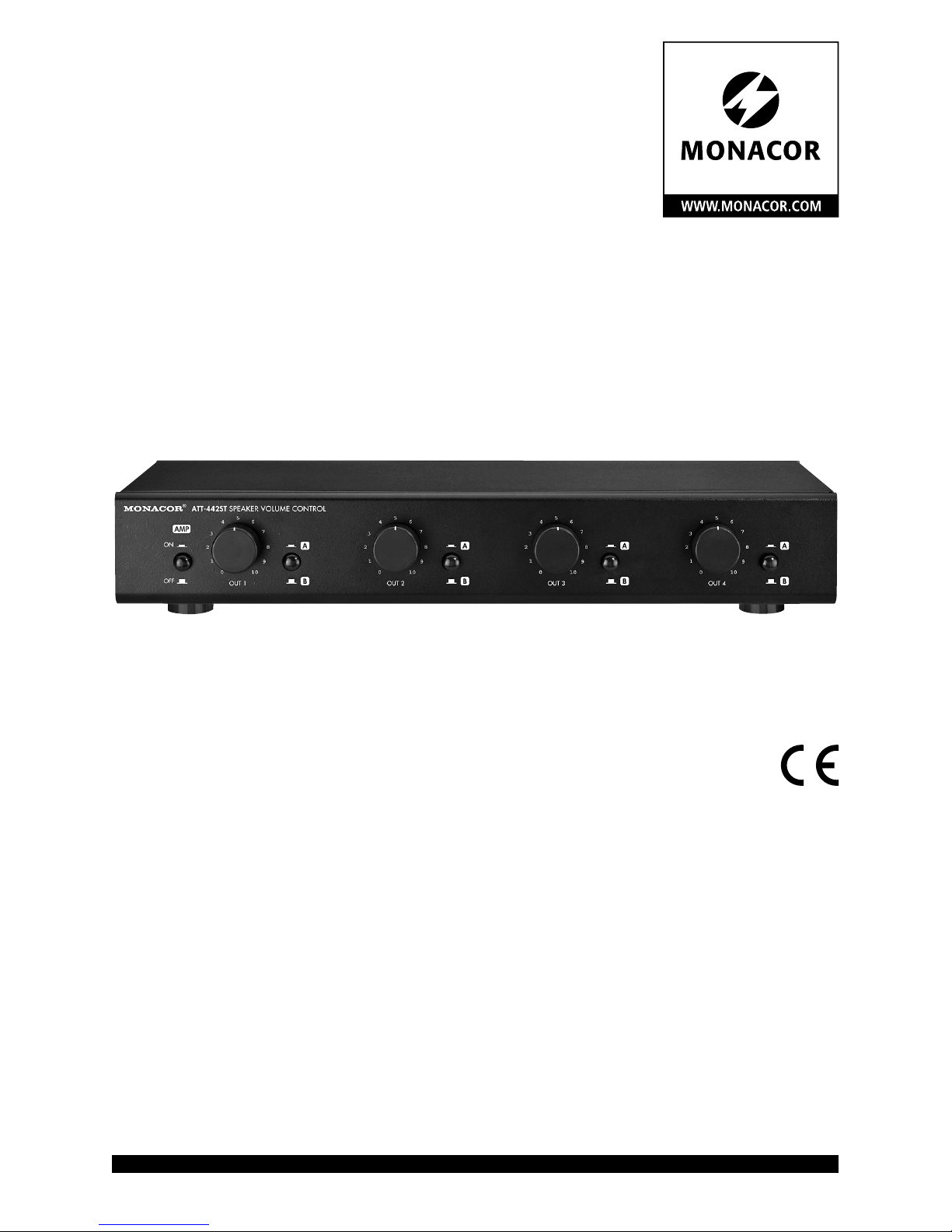
ATT-442ST
Bestell-Nr. • Order No. 17.1860
Lautsprecher-Lautstärkesteller
für 4 Zonen
Speaker Attenuator
for 4 Zones
Page 2

2
Page 3
3
ELECTRONICS FOR SPECIALISTS ELECTRONICS FOR SPECIALISTS ELECTRONICS FOR SPECIALISTS ELECTRONICS FOR SPECIALISTS
Deutsch ..........Seite 4
English ...........Page 5
Français ..........Page 6
Italiano...........Pagina 7
Español ..........Página 8
Polski ............Strona 9
LR
FROM
AMP B
LR
FROM
AMP A
LR
TO
SPKR 3
LR
TO
SPKR 4
LR
TO
SPKR 1
LR
TO
SPKR 2
POWER
CLIP
R-CH
STA-400D
CLIP
L-CH
100 100
ON
PROTECT
POWER
CLIP
R-CH
STA-400D
CLIP
L-CH
100 100
ON
PROTECT
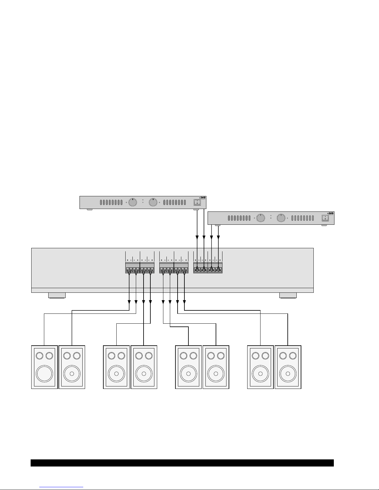
Stereo Speakers 4
Amplifier A
Amplifier B (optional)
Stereo Speakers 3 Stereo Speakers 2 Stereo Speakers 1
ATT-442ST
Anschluss • Connection • Branchement • Collegamento • Conexión • Połączenie
Page 4
4
Deutsch
5
B
8
A
AMP
ON
OFF
0
1
2
3
4
6
7
9
10
OUT 1
5
B
8
A
0
1
2
3
4
6
7
9
10
OUT 2
5
B
8
A
0
1
2
3
4
6
7
9
10
OUT 3
5
B
8
A
0
1
2
3
4
6
7
9
10
OUT 4
ATT-442ST SPEAKER VOLUME CONTROL
2 3 3 3 31 2 2 2
Lautsprecher-Lautstärkesteller
Diese Bedienungsanleitung richtet sich an Benutzer
ohne besondere Fachkenntnisse. Bitte lesen Sie die
Anleitung vor dem Betrieb gründlich durch und heben
Sie sie für ein späteres Nachlesen auf.
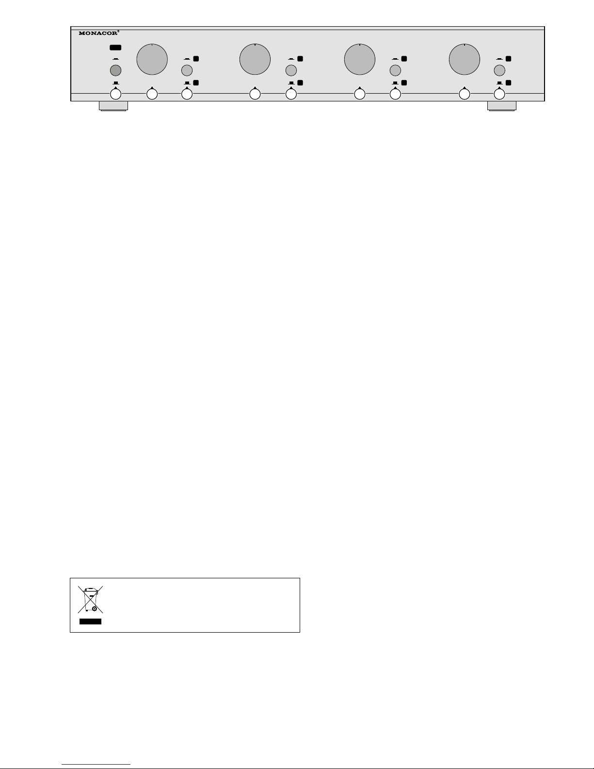
1 Übersicht
1
Taste AMP zum Ein- und Ausschalten aller angeschlossenen Lautsprecher
2
Lautstärkeregler für die einzelnen Lautsprecherpaare
3
Tasten für jedes Lautsprecherpaar zum Umschalten
zwischen Verstärker A und B
4 Schraubklemmen* für die Lautsprecher
5
Schraubklemmen* zum Anschluss an die Lautsprecherausgänge des Verstärkers A
6
Schraubklemmen* zum Anschluss an die Lautsprecherausgänge des Verstärkers B
* Die Schraubklemmen lassen sich zur besseren Hand-
habung aus ihren Steckverbindung herausziehen.
2 Wichtige Hinweise für den Gebrauch
•
Das Gerät ist nur zur Verwendung im Innenbereich
geeignet. Schützen Sie es vor Tropf- und Spritzwasser, hoher Luftfeuchtigkeit und Hitze (zulässiger
Einsatztemperaturbereich 0 – 40 °C).
•
Verwenden Sie für die Reinigung nur ein trockenes,
weiches Tuch, auf keinen Fall Chemikalien oder
Wasser.
•
Wird das Gerät zweckentfremdet, nicht richtig angeschlossen, überlastet, falsch bedient oder nicht
fachgerecht repariert, kann keine Haftung für daraus resultierende Sach- oder Personenschäden und
keine Garantie für das Gerät übernommen werden.
Soll das Gerät endgültig aus dem Betrieb
genommen werden, übergeben Sie es zur
umweltgerechten Entsorgung einem örtlichen Recycling betrieb.
3 Verwendungsmöglichkeiten
Der 4-Zonen-Stereo-Lautstärkesteller ist speziell für
den Einsatz in Audioanlagen konzipiert, um für verschiedene Beschallungszonen unterschiedliche Lautstärken einstellen zu können. Das Gerät wird zwischen
die Stereo-Lautsprecherausgänge des Endverstärkers
und die Stereo-Lautsprecher (Impedanz 4 – 16 Ω)
geschaltet. Es können zwei Stereoverstärker angeschlossen werden (max. 100 W pro Kanal). Für jedes
Lautsprecherpaar lässt sich separat das Stereosignal
von einem der beiden Verstärker anwählen.
4 Elektrischer Anschluss
Falls die anzuschließenden Verstärker eingeschaltet
sind, diese zuerst ausschalten!
1)
Zur besseren Handhabung lassen sich die Anschlussklemmen (4 – 6) aus ihren Steckverbindungen herausziehen. Beim Wiederhineinstecken darauf achten, dass sie auf die richtigen Pins gesteckt
werden!
2)
Die Pluspole der Verstärkerausgänge und der Lautsprecher immer mit dem entsprechenden Klemmkontakt „+“ verbinden und die Minuspole mit „−“.
3)
Der komplette Anschluss ist auf der Seite 3 dargestellt. Die Lautsprecherausgänge des Verstärkers
an die Klemmen FROM AMP A (5) anschließen.
Wird ein zweiter Verstärker verwendet, diesen mit
den Klemmen FROM AMP B (6) verbinden.
4) Die Lautsprecher an die Klemmen TO SPKR 1 bis
TO SPKR 4 (4) anschließen. Es können auch Lautsprecher mit unterschiedlichen Impedanzen (4 Ω
bis16 Ω) verwendet werden.
5 Bedienung
1) Bei der ersten Inbetriebnahme zuerst alle Lautstärkeregler (2) ganz nach links auf null drehen. Dann
erst die angeschlossenen Verstärker einschalten.
2) Die Taste AMP (1) hineindrücken. Damit sind alle
Lautsprecher eingeschaltet.
3) Für jedes Lautsprecherpaar separat mit den Tasten
A / B (3) wählen, welches Verstärkersignal wiedergegeben werden soll.
4)
Mit den Lautstärkereglern (2) jeweils die gewünschte Lautstärke einstellen.
5) Sollen alle Lautsprecher ausgeschaltet werden, die
Taste AMP (1) ausrasten.
6 Technische Daten
Siehe Seite 10.
Änderungen vorbehalten.
Page 5

5
English
LR
FROM
AMP B
LR
FROM
AMP A
LR
TO
SPKR 3
LR
TO
SPKR 4
LR
TO
SPKR 1
LR
TO
SPKR 2
5
B
8
A
AMP
ON
OFF
0
1
2
3
4
6
7
9
10
OUT 1
5
B
8
A
0
1
2
3
4
6
7
9
10
OUT 2
5
B
8
A
0
1
2
3
4
6
7
9
10
OUT 3
5
B
8
A
0
1
2
3
4
6
7
9
10
OUT 4
ATT-442ST SPEAKER VOLUME CONTROL
4
2 3 3 3 31 2 2 2
4 5 6
Speaker Attenuator
These instructions are intended for users without any
specific technical knowledge. Please read these instructions carefully prior to operation and keep them
for later reference.
1 Overview
1
Button AMP to switch on and off all connected
speakers
2 Volume controls for the individual speaker pairs
3
Buttons for each speaker pair to select amplifier
A or B
4 Screw terminals* for the speakers
5
Screw terminals* for connection to the speaker
outputs of amplifier A
6
Screw terminals* for connection to the speaker
outputs of amplifier B
* For better handling, the screw terminals can be removed
from their plug-in connections.
2 Important Notes
•
The unit is suitable for indoor use only. Protect it
against dripping water and splash water, high air
humidity and heat (admissible ambient temperature
range 0 – 40 °C).
•
For cleaning only use a dry, soft cloth; never use
chemicals or water.
•
No guarantee claims for the unit and no liability for
any resulting personal damage or material damage
will be accepted if the unit is used for other purposes than originally intended, if it is not correctly
connected or operated, if it is overloaded, or if it is
not repaired in an expert way.
If the unit is to be put out of operation
definitively, take it to a local recycling plant
for a disposal which is not harmful to the
environment.
3 Applications
The 4-zone stereo attenuator is especially designed
for use in audio systems so that different volumes
can be adjusted for different PA zones. The unit is
inserted between the stereo speaker outputs of the
power amplifier and the stereo speakers (impedance
4 – 16 Ω). It is possible to connect two stereo amplifiers
(max. 100 W per channel). The stereo signal of one
of the two amplifiers can separately be selected for
each speaker pair.
4 Electrical Connection
If the amplifiers to be connected are switched on,
switch them off first!
1)
For better handling, the connection terminals
(4 to 6) can be removed from their plug-in connections. When replugging them, make sure that they
are plugged onto the correct pins!
2) Always connect the positive poles of the amplifier
outputs and speakers to the corresponding clamping contact “+” and the negative poles to “−”.
3)
The complete connection is shown on page 3.
Connect the speaker outputs of the amplifier to the
terminals FROM AMP A (5). If a second amplifier is
used, connect it to the terminals FROM AMP B (6).
4) Connect the speakers to the terminals TO SPKR1
to TO SPKR 4 (4). It is also possible to use speakers
of different impedances (4 Ω to 16 Ω).
5 Operation
1) When setting the unit into operation for the first
time, turn all volume controls (2) to the left stop to
zero before switching on the connected amplifiers.
2) Engage the button AMP (1). Thus, all speakers are
switched on.
3) Use the appropriate buttons A / B (3) to define for
each speaker pair the amplifier whose signals are
to be reproduced.
4) Use the appropriate volume controls (2) to adjust
the volume desired for each speaker pair.
5)
To switch off all speakers, disengage the button
AMP (1).
6 Specifications
See page 10.
Subject to technical modification.
Page 6

6
Français
5
B
8
A
AMP
ON
OFF
0
1
2
3
4
6
7
9
10
OUT 1
5
B
8
A
0
1
2
3
4
6
7
9
10
OUT 2
5
B
8
A
0
1
2
3
4
6
7
9
10
OUT 3
5
B
8
A
0
1
2
3
4
6
7
9
10
OUT 4
ATT-442ST SPEAKER VOLUME CONTROL
2 3 3 3 31 2 2 2
Atténuateur haut-parleurs
Cette notice s‘adresse aux utilisateurs sans connaissances
techniques particulières. Veuillez lire la présente notice
avec attention avant le fonctionnement et conservez-la
pour pouvoir vous y reporter ultérieurement.
1 Vue d’ensemble
1
Touche AMP pour allumer et éteindre tous les hautparleurs reliés
2
Réglages de volume séparément pour chaque paire
de haut-parleurs
3 Touches pour chaque paire de haut-parleurs pour
commuter entre amplificateur A et B
4 Bornes à vis* pour les haut-parleurs
5
Bornes à vis* pour brancher aux sorties haut-parleur
de l’amplificateur A
6
Bornes à vis* pour brancher aux sorties haut-parleur
de l’amplificateur B
* Les bornes à vis peuvent être retirées de leur emplace-
ment pour une meilleure manipulation.
2 Conseils importants d’utilisation
•
L’appareil n’est conçu que pour une utilisation en
intérieur. Protégez-le des éclaboussures, de tout
type de projections d’eau, de l’humidité élevée et
de la chaleur (température ambiante admissible
0 – 40 °C).
•
Pour le nettoyage, utilisez un chiffon sec et doux, en
aucun cas de produits chimiques ou d’eau.
•
Nous déclinons toute responsabilité en cas de dommages corporels ou matériels résultants si l’appareil
est utilisé dans un but autre que celui pour lequel
il a été conçu, s’il n’est pas correctement branché
ou utilisé, s’il y a surcharge ou s’il n’est pas réparé
par un technicien habilité ; de même, la garantie
deviendrait caduque.
Lorsque l’appareil est définitivement retiré
du service, vous devez le déposer dans une
usine de recyclage adaptée pour contribuer
à son élimination non polluante.
CARTONS ET EMBALLAGE
PAPIER À TRIER
3 Possibilités d’utilisation
L’atténuateur stéréo 4 zones est spécialement conçu
pour une utilisation dans des installations audio de
manière à pouvoir régler des volumes distincts pour
des zones différentes de sonorisation. L’appareil est
branché entre les sorties stéréo haut-parleurs de
l’amplificateur et les haut-parleurs stéréo (impédance
4 – 16 Ω). On peut connecter deux amplificateurs stéréo (100 W max. par canal). Le signal stéréo de l’un des
deux amplificateurs peut être sélectionné séparément
pour chaque paire de haut-parleurs.
4 Branchement électrique
Si les amplificateurs à relier sont allumés, éteignez-les
tout d’abord !
1) Pour une meilleure manipulation, il est possible de
retirer les bornes de branchement (4 – 6) de leur
emplacement. Lorsque vous les replacez, faites attention à ce qu’elles soient placées sur les bons pins.
2) Reliez toujours les pôles plus des sorties amplificateur et des haut-parleurs au contact «+» correspondant de la borne et les pôles moins au contact «−».
3)
La page 3 présente le branchement complet.
Connectez les sorties haut-parleurs de l’amplificateur
aux bornes FROM AMP A (5). Si un second amplifica
-
teur est utilisé, reliez-le aux bornes FROM AMP B (6).
4)
Connectez les haut-parleurs aux bornes TO SPKR1 à
TO SPKR 4 (4) ; on peut également utiliser des hautparleurs avec des impédances différentes (4 Ω à 16 Ω).
5 Utilisation
1)
Lors de la première utilisation, mettez tout d’abord
l’ensemble des réglages de volume (2) entièrement
à gauche sur zéro. Allumez ensuite les amplificateurs reliés.
2)
Enfoncez la touche AMP (1), tous les haut-parleurs
sont ainsi allumés.
3) Avec les touches A / B (3), sélectionnez séparément
pour chaque paire de haut-parleurs quel signal
d’amplification doit être restitué.
4)
Avec les réglages de volume correspondants (2),
réglez séparément le volume souhaité pour chaque
paire de haut-parleurs.
5)
Désenclenchez la touche AMP (1) pour éteindre
tous les haut-parleurs.
6 Caractéristiques techniques
Voir page 10.
Tout droit de modification réservé.
Page 7

7
Italiano
LR
FROM
AMP B
LR
FROM
AMP A
LR
TO
SPKR 3
LR
TO
SPKR 4
LR
TO
SPKR 1
LR
TO
SPKR 2
5
B
8
A
AMP
ON
OFF
0
1
2
3
4
6
7
9
10
OUT 1
5
B
8
A
0
1
2
3
4
6
7
9
10
OUT 2
5
B
8
A
0
1
2
3
4
6
7
9
10
OUT 3
5
B
8
A
0
1
2
3
4
6
7
9
10
OUT 4
ATT-442ST SPEAKER VOLUME CONTROL
4
2 3 3 3 31 2 2 2
4 5 6
Attenuatore per altoparlanti
Queste istruzioni sono rivolte all’utente senza conoscenze tecniche specifiche. Vi preghiamo di leggerle
attentamente prima della messa in funzione e di conservarle per un uso futuro.
1 Panoramica
1 Tasto AMP per accendere e spegnere tutti gli alto-
parlanti collegati
2
Regolatori volume per le singole coppie di altoparlanti
3 Tasti per ogni coppia di altoparlanti per cambiare
fra gli amplificatori A e B
4 Morsetti a vite* per gli altoparlanti
5 Morsetti a vite* per il collegamento con le uscite
per altoparlanti dell’amplificatore A
6 Morsetti a vite* per il collegamento con le uscite
per altoparlanti dell’amplificatore B
* Per maggiore comodità, i morsetti a vite si possono sfilare
dalla loro sede.
2 Avvertenze importanti per l’uso
•
Lo strumento è previsto solo per l’uso all’interno
di locali. Proteggerlo dall’acqua gocciolante e dagli
spruzzi d’acqua, da alta umidità dell’aria e dal calore
(temperatura d’impiego ammessa fra 0 e 40 °C).
•
Per la pulizia usare solo un panno morbido, asciutto;
non impiegare in nessun caso prodotti chimici o
acqua.
•
Nel caso d’uso improprio, di collegamenti sbagliati,
di sovraccarico dell’apparecchio, d’impiego scorretto o di riparazione non a regola d’arte non si
assume nessuna responsabilità per eventuali danni
consequenziali a persone o a cose e non si assume
nessuna garanzia per lo strumento.
Se si desidera eliminare l’apparecchio definitivamente, consegnarlo per lo smaltimento
ad un’istituzione locale per il riciclaggio.
3 Possibilità d’impiego
L’attenuatore a 4 zone è stato realizzato specialmente
per l’impiego in impianti audio per poter impostare dif
ferenti livelli di volume in varie zone di sonorizzazione.
Lo strumento viene inserito fra le uscite stereo per
altoparlanti del finale e gli altoparlanti stereo (impedenza 4 – 16 Ω). Si possono collegare due amplificatori
stereo (max. 100 W per canale). Per ogni coppia di
altoparlanti è possibile selezionare separatamente il
segnale stereo di uno dei due amplificatori.
4 Collegamento elettrico
Se gli amplificatori da collegare sono accesi occorre
dapprima spegnerli!
1)
Per maggiore comodità, i morsetti di collegamento
(4 – 6) si possono sfilare dalla loro sede. Nell’in serirli
di nuovo fare attenzione da rimetterli sui pin giusti!
2)
Collegare i poli positivi delle uscite degli amplificatori e degli altoparlanti sempre con il relativo
morsetto “+” , e i poli negativi con “−”.
3)
La pagina 3 illustra il collegamento completo.
Collegare le uscite per altoparlanti dell’amplificatore con i morsetti FROM AMP A (5). Se si utilizza
un secondo amplificatore, collegarlo con i morsetti
FROM AMP B (6).
4)
Collegare gli altoparlanti con i morsetti TO SPKR1 a
TO SPKR 4 (4). Si possono usare anche altoparlanti
con impedenza differente (da 4 Ω a 16 Ω).
5 Funzionamento
1) In occasione della prima messa in funzione, girare
dapprima tutti i regolatori del volume (2) completamente a sinistra sullo zero. Solo allora accendere
gli amplificatori collegati.
2) Spingere in giù il tasto AMP (1). In questo modo,
tutti gli altoparlanti sono accesi.
3) Per ogni coppia di altoparlanti scegliere separatamente con i tasti A / B (3) il segnale dell’amplificatore
da riprodurre.
4)
Con i regolatori del volume (2) impostare il volume
desiderato di volta in volta.
5) Se si devono spegnere tutti gli altoparlanti, sbloccare il tasto AMP (1).
6 Dati tecnici
Vedi pagina 11.
Con riserva di modifiche tecniche.
Page 8

8
Español
5
B
8
A
AMP
ON
OFF
0
1
2
3
4
6
7
9
10
OUT 1
5
B
8
A
0
1
2
3
4
6
7
9
10
OUT 2
5
B
8
A
0
1
2
3
4
6
7
9
10
OUT 3
5
B
8
A
0
1
2
3
4
6
7
9
10
OUT 4
ATT-442ST SPEAKER VOLUME CONTROL
2 3 3 3 31 2 2 2
Atenuador de Altavoces
Estas instrucciones van dirigidas a usuarios sin ningún conocimiento técnico específico. Lea atentamente
estas instrucciones antes de utilizar el aparato y guárdelas para usos posteriores.
1 Vista General
1 Botón AMP para encender y apagar todos los alta-
voces conectados
2 Controles de volumen para las parejas individuales
de altavoces
3
Botones para cada pareja de altavoces para conmutar entre amplificador A y B
4 Terminales de tornillo* para los altavoces
5 Terminales de tornillo* para conectar a las salidas
de altavoz del amplificador A
6 Terminales de tornillo* para conectar a las salidas
de altavoz del amplificador B
* Los terminales de tornillo pueden sacarse para una mejor
manipulación.
2 Notas Importantes
•
El aparato está adecuado para utilizarse sólo en interiores. Protéjalo de goteos y salpicaduras, elevada
humedad del aire y calor (temperatura ambiente
admisible: 0 – 40 °C).
•
Utilice sólo un paño suave y seco para la limpieza;
no utilice nunca ni agua ni productos químicos.
•
No podrá reclamarse garantía o responsabilidad
alguna por cualquier daño personal o material
resultante si el aparato se utiliza para otros fines
diferentes a los originalmente concebidos, si no se
conecta o utiliza adecuadamente, si se sobrecarga
o si no se repara por expertos.
Si va a poner el aparato definitivamente
fuera de servicio, llévelo a la planta de reciclaje más cercana para que su eliminación
no sea perjudicial para el medioambiente.
3 Aplicaciones
El atenuador estéreo 4 zonas está especialmente diseñado para su utilización en instalaciones audio de
manera que se pueda ajustar volúmenes distintos para
zonas diferentes de megafonía. El aparato está insertado entre las salidas estéreo de altavoz del amplificador de potencia y los altavoces (impedancia: 4 – 16 Ω).
Se pueden conectar dos amplificadores estéreo (100 W
máx. por canal). La señal estéreo de uno de los amplificadores se puede seleccionar separadamente para
cada pareja de altavoces.
4 Conexión Eléctrica
¡Si los amplificadores que hay que conectar están
encendidos, apáguelos primero!
1) Los terminales de conexión (4 – 6) pueden sacarse
para una mejor manipulación. Cuando coloque los
terminales, asegúrese de colocarlos en los pines
correctos.
2)
Conecte siempre los polos positivos de las salidas de amplificador y de los altavoces al contacto
“+” correspondiente y los polos negativos al contacto“−”.
3)
La página 3 presenta la conexión completa.
Conecte las salidas de altavoz del amplificador a
los terminales FROM AMP A (5). Si se utiliza un
segundo amplificador, conéctelo a los terminales
FROM AMP B (6).
4)
Conecte los altavoces a los terminales TO SPKR 1 a
TO SPKR 4 (4); también se puede utilizar altavoces
con impedancias diferentes (4 a 16 Ω).
5 Utilización
1) Durante la primera utilización, primero gire todos
los controles de volumen (2) hasta el tope izquierdo
en la posición cero. Conecte después los amplificadores.
2)
Encaje el botón AMP (1); todos los altavoces se
encienden.
3)
Utilice los botones apropriados A / B (3) para definir
para cada pareja de altavoces el amplificador cuyos
señales tenga que reproducir.
4)
Utilice los controles de volumen apropriados (2)
para ajustar el volumen deseado de cada pareja
de altavoces.
5)
Desencaje el botón AMP (1) para apagar todos
los altavoces.
6 Especificaciones
Vea página 11.
Sujeto a modificaciones técnicas.
Page 9

9
Polski
LR
FROM
AMP B
LR
FROM
AMP A
LR
TO
SPKR 3
LR
TO
SPKR 4
LR
TO
SPKR 1
LR
TO
SPKR 2
5
B
8
A
AMP
ON
OFF
0
1
2
3
4
6
7
9
10
OUT 1
5
B
8
A
0
1
2
3
4
6
7
9
10
OUT 2
5
B
8
A
0
1
2
3
4
6
7
9
10
OUT 3
5
B
8
A
0
1
2
3
4
6
7
9
10
OUT 4
ATT-442ST SPEAKER VOLUME CONTROL
4
2 3 3 3 31 2 2 2
4 5 6
Regulator głośności
Niniejsza instrukcja przeznaczona jest dla użytkowników, którzy nie posiadają wiedzy i doświadczenia
technicznego. Przed rozpoczęciem użytkowania proszę zapoznać się z instrukcją, a następnie zachować
ją do wglądu.
1 Elementy użytkowe i złącza
1
Przycisk AMP włączający / wyłączający wszystkie
podłączone głośniki
2 Regulatory głośności dla poszczególnych par gło-
śników
3 Przyciski wyboru wzmacniacza A lub B
4 Gniazda* głośnikowe
5
Gniazdo* do podłączenia wyjścia głośnikowego
wzmacniacza A
6
Gniazdo* do podłączenia wyjścia głośnikowego
wzmacniacza B
* Dla wygody podłączania gniazda te można wyjąć ze
wzmacniacza.
2 Środki ostrożności
•
Urządzenie to przeznaczone jest tylko do użytku
wewnątrz pomieszczeń. Należy chronić je przed
wilgocią i wysoką temperaturą (średnia temperatura otoczenia powinna zawierać się w przedziale
od 0 do 40 °C).
•
Do czyszczenia regulatorów należy używać tylko
suchej miękkiej szmatki. Nie wolno używać do tego
celu wody lub środków chemicznych.
•
Nie ponosi się odpowiedzialności za wynikłe
uszkodzenia sprzętu lub obrażenia użytkownika w
przypadku, gdy urządzenie jest wykorzystywane
w innych celach niż to się przewiduje lub, jeśli jest
nieodpowiednio zainstalowane, użytkowane lub
naprawiane.
Aby nie zaśmiecać środowiska po całkowitym zakończeniu eksploatacji urządzenia
należy je oddać do punktu recyklingu.
3 Zastosowanie
ATT-442ST jest 4-strefowym, stereofonicznym regulatorem głośności (tłumikiem) przeznaczonym do użytku
w systemach audio. Regulator jest włączany w tor
pomiędzy wyjście głośnikowe wzmacniacza mocy a
zestawy głośnikowe (4 – 16 Ω). Do urządzenia można
podłączyć dwa stereofoniczne wzmacniacze mocy o
mocy maksymalnej 100 W na kanał. Za pomocą przełącznika, dla każdego kanału można wybrać źródło
sygnału (wzmacniacz).
4 Podłączenia elektryczne
Przed dokonywaniem jakichkolwiek podłączeń należy
bezwzględnie wyłączyć wzmacniacze mocy!
1)
Dla wygody podłączania, gniazda (4 – 6) można
wyjąć ze wzmacniacza. Przy wkładaniu z powrotem
należy zwrócić uwagę na poprawność podłączenia.
2)
Należy zwrócić uwagę na odpowiednią polaryzację
podłączenia: zacisk dodatni wzmacniacza połączyć
z zaciskiem dodatnim regulatora, ujemny z ujemnym.
3)
Pełny schemat połączeń pokazano na stronie 3.
Wyjścia głośnikowe wzmacniacza podłączyć do
gniazd FROM AMP A (5). Jeśli podłączany będzie
drugi wzmacniacz, należy go podpiąć do gniazd
FROM AMP B (6).
4)
Zestawy głośnikowe należy podłączyć do gniazd TO
SPKR 1 do TO SPKR4 (4). Można używać zestawów
o różnych impedancjach (w zakresie od 4 do 16 Ω).
5 Obsługa
1)
Uruchamiając system pierwszy raz, wszystkie regulatory głośności (2) należy ustawić na minimum.
2)
Wycisnąć przycisk AMP (1) – wszystkie głośniki
zostaną włączone.
3) Za pomocą przełącznika A / B (3) wybrać źródło sygnału (wzmacniacz).
4) Ustawić regulatorami (2) wymaganą głośność dla
każdego z zestawów.
5)
Aby wyłączyć wszystkie głośniki należy wcisnąć
przycisk AMP (1).
6 Dane techniczne
Patrz na stronie 11.
Z zastrzeżeniem do możliwych zmian.
Page 10

10
DE – Technische Daten GB – Specifications
FR – Caractéristiques
techniques
ATT-442ST
Eingangsbelastbarkeit
pro Kanal
Input power rating
per channel
Puissance d’entrée
par canal
100 W max.
Ausgangsleistung
pro Kanal
Output power
per channel
Puissance de sortie
par canal
18 W max.
Lautsprecherimpedanz Speaker impedance Impédance haut-parleurs 4 – 16 Ω
Frequenzbereich Frequency range Bande passante 20 – 20 000 Hz
Einsatztemperatur Ambient temperature Température fonc. 0 – 40 °C
Abmessungen (B × H × T) Dimensions (W × H × D) Dimensions (l × h × p) 432 × 78 × 190 mm
Gewicht Weight Poids 3,4 kg
Diese Bedienungsanleitung ist urheberrechtlich für MONACOR ® INTERNATIONAL GmbH & Co. KG geschützt. Eine
Reproduktion für eigene kommerzielle Zwecke – auch auszugsweise – ist untersagt.
All rights reserved by MONACOR ® INTERNATIONAL GmbH & Co. KG. No part of this instruction manual may be
reproduced in any form or by any means for any commercial use.
Notice d’utilisation protégée par le copyright de MONACOR ® INTERNATIONAL GmbH & Co. KG. Toute reproduction
même partielle à des fins commerciales est interdite.
Page 11

11
IT – Dati tecnici ES – Especificaciones PL – Specyfikacja ATT-442ST
Potenza all’ingresso
per canale
Potencia de entrada
por canal
Znamionowa moc wejściow
na kanał
100 W max.
Potenza all’uscita
per canale
Potencia de salida
por canal
Moc wyjściowa
na kanał
18 W max.
Impedenza
degli altoparlanti
Impedancia altavoces Impedancja zestawów 4 – 16 Ω
Gamma di frequenze Rango de frecuencias Pasmo przenoszenia 20 – 20 000 Hz
Temperatura d’esercizio Temperatura ambiente Temperatura pracy 0 – 40 °C
Dimensioni (l × h × p) Dimensiones (B × H × P) Wymiary (S × W × G) 432 × 78 × 190 mm
Peso Peso Waga 3,4 kg
La MONACOR ® INTERNATIONAL GmbH & Co. KG si riserva ogni diritto di elaborazione in qualsiasi forma delle
presenti istruzioni per l’uso. La riproduzione – anche parziale – per propri scopi commerciali è vietata.
Manual de instrucciones protegido por el copyright de MONACOR ® INTERNATIONAL GmbH & Co. KG. Toda
reproducción mismo parcial para fines comerciales está prohibida.
Instrukcje obsługi są chronione prawem copyright for MONACOR ® INTERNATIONAL GmbH & Co. KG. Przetwarzanie
całości lub części instrukcji dla osobistych korzyści finansowych jest zabronione.
Page 12

MONACOR INTERNATIONAL GmbH & Co. KG • Zum Falsch 36 • 28307 Bremen • Germany
Copyright © by MONACOR INTERNATIONAL. All rights reserved. A-0349.99.03.01.2018
 Loading...