

Monaco HOLIDAY RAMBLER 2013 Owner's Manual

1953-2013
60 YEARS
2013
Owners Manual

monaco RV Towable limiTed waRRanTy - 2013
i
MONACO RV TOWABLE LIMITED WARRANTY - 2013
WHAT THE PERIOD OF COVERAGE IS:
The Limited Warranty provided by Monaco RV, LLC (“Warrantor”) covers
those components, assemblies and systems of your new towable product not
excluded under the section “What The Warranty Does Not Cover” and when sold
by an authorized dealer, for twelve (12) months from the original retail purchase
date. However, this Limited Warranty covers the internal steel or aluminum
structural support frames inside the walls and roof (excluding slide-outs) for
sixty (60) months from the original retail purchase date. If you use your towable
product for any rental, commercial or business purposes whatsoever, the Limited
Warranty provided by Warrantor covers your new towable product when sold by
an authorized dealer for ninety (90) days from the original retail purchase date, and
it covers the internal steel or aluminum structural support frames inside the walls
and roof (excluding slide-outs) for twelve (12) months from the original retail
purchase date. A conclusive presumption that your towable product has been used
for commercial and/or business purposes arises if you have led any tax or other
form claiming any business use, ownership, or tax benet related to your towable
product.
THIS LIMITED WARRANTY IS LIMITED TO THE ORIGINAL
CONSUMER PURCHASER AND IS NOT TRANSFERABLE.
LIMITATION AND DISCLAIMER OF IMPLIED WARRANTIES:
IMPLIED WARRANTIES, IF ANY, ARISING BY WAY OF STATE LAW,
INCLUDING ANY IMPLIED WARRANTY OF MERCHANTABILITY
AND ANY IMPLIED WARRANTY OF FITNESS FOR A PARTICULAR
PURPOSE, ARE LIMITED IN DURATION TO THE TERM OF THIS
LIMITED WARRANTY AND ARE LIMITED IN SCOPE OF COVERAGE
TO THOSE PORTIONS OF THE TOWABLE PRODUCT COVERED BY
THIS LIMITED WARRANTY. WARRANTOR DISCLAIMS ALL IMPLIED
AND EXPRESS WARRANTIES, INCLUDING THE IMPLIED WARRANTY
OF MERCHANTABILITY AND THE IMPLIED WARRANTY OF FITNESS
FOR A PARTICULAR PURPOSE, ON COMPONENTS AND APPLIANCES
EXCLUDED FROM COVERAGE AS SET FORTH BELOW. There is no
warranty of any nature made by Warrantor beyond that contained in this Limited
Warranty. No person has authority to enlarge, amend or modify this Limited
Warranty. The dealer is not the Warrantor’s agent but is an independent entity.
Warrantor is not responsible for any undertaking, representation or warranty made
by any dealer or other person beyond those expressly set forth in this Limited
Warranty. Some states do not allow limitations on how long an implied warranty
lasts, so the above limitation may not apply to you.
WHAT THE WARRANTY COVERS:
Warrantor’s Limited Warranty covers “mechanical defects” in the manufacture
of your towable product. “Mechanical Defect” means a nonconforming condition
that substantially impairs the use and operation of the towable product. Also see the
section “What the Warranty Does Not Cover” set out below.
WHAT WE WILL DO TO CORRECT PROBLEMS:
Warrantor’s sole and exclusive obligation is to repair and/or replace, at its
option, any covered defect if: (1) you notify Warrantor or one of its authorized
servicing dealers of the defect within the warranty coverage period and within ve
(5) days of discovering the defect; and (2) you deliver your towable product to
Warrantor or Warrantor’s authorized servicing dealer at your cost and expense. It is
reasonable to expect some service items to occur during the warranty period. The
performance of warranty repairs shall not extend the original warranty coverage
period. Further, any performance of repairs after the warranty coverage period
has expired or any performance of repairs to component parts and appliances that
are excluded from coverage shall be considered “good will” repairs, which shall
not alter the express terms of this Limited Warranty. If the repair or replacement
remedy fails to successfully cure a defect after Warrantor received a reasonable
opportunity to cure the defect(s), your sole and exclusive remedy shall be limited
to Warrantor paying you the cost of having an independent third party perform
repair(s) to the defect(s). Warrantor may use new and/or remanufactured parts and/
or components of substantially equal quality to complete any repair.
Imperfections and/or damage to interior and exterior surfaces, trim, upholstery
and other appearance items may occur at the factory during manufacture, during
delivery of the towable product to the selling dealer or on the selling dealer’s lot.
Normally, any such imperfections are detected and corrected at the factory or by
the selling dealer during the inspection process performed by the Warrantor and the
selling dealer. If, however, you discover any such imperfection or damage when
you take delivery of the towable product, you must notify your dealer or Warrantor
within thirty (30) days of the date of purchase to have repairs performed at no cost
to you in accordance with this Limited Warranty. If not reported within this time,
such imperfections are conclusively presumed to be the result of normal wear and
tear.
If a servicing dealer is unable or unwilling to solve a problem you are convinced
is covered by the Limited Warranty, or that concerns the safety of your towable
product, or that may involve local consumer protection or “lemon” laws, then you
must, to the extent permitted by law, notify Warrantor directly in writing of the
failure to successfully repair the defect(s) so that Warrantor can become directly
involved in performing a successful repair.
HOW TO GET SERVICE:
The “Acknowledgement of Receipt of Warranty/Production Information”
form must be returned to Warrantor promptly upon purchase to assure proper
part replacement or repair of your towable product. Failure to return the
“Acknowledgement of Receipt of Warranty/Production Information” form will
not affect your rights under the Limited Warranty so long as you can furnish
proof of purchase. For warranty service simply contact one of Warrantor’s
authorized service centers for an appointment, then deliver your towable product
(at your expense) to the service center. If you need assistance in locating an
authorized warranty service facility, contact Warrantor’s Warranty Department::
(1-877-466-6226).

monaco RV Towable limiTed waRRanTy - 2013
ii
HOW TO GET SERVICE (cont’d):
The Warrantor’s mailing address is:
Monaco RV, LLC
606 Nelsons Parkway
Wakarusa, Indiana 46573
Because Warrantor does not control the scheduling of service work by
authorized servicing dealers, you may encounter some delay in scheduling and/or
in the completion of the repairs.
WHAT THE WARRANTY DOES NOT COVER:
This Limited Warranty does not cover: any towable product sold or registered
outside of the United States or Canada; exterior berglass and gel coat; items
which are added or changed after the towable product leaves Warrantor’s
possession; items that are working as designed but which you are unhappy with
because of the design; normal wear and usage, such as fading or discoloration
of fabrics, or the effects of moisture inside the towable product; defacing,
scratching, dents and chips on any surface or fabric of the towable product;
owner maintenance, including by way of example resealing exterior sealant
areas; appliances and components covered by their own manufacturer’s warranty
including, by way of example the tires, batteries, gauges, microwave, refrigerator,
ice maker, stove, oven, generator, roof air conditioners, jacks, VCR, television(s),
water heater, furnace, stereo, radio, compact disc player, washer, dryer, inverter
and cellular phone; aking, peeling and chips or other defects or damage in or to
the exterior or nish caused by road hazards, airborne pollutants, salt, tree sap,
hail, or any other cause. Component part and appliance manufacturers issue limited
warranties covering portions of the towable product not covered by the Limited
Warranty issued by Warrantor. To learn more on what specic component parts
and appliances are excluded from the Limited Warranty issued by Warrantor please
contact your selling dealership or Warrantor directly or review the warranty packet
inside the towable product.
EVENTS DISCHARGING WARRANTOR FROM OBLIGATION
UNDER WARRANTY:
Misuse or neglect, accidents, unauthorized alteration, failure to provide
reasonable and necessary maintenance (See Owner’s Manual), damage caused
by off road use, collision, re, theft, vandalism, explosions, and overloading in
excess of the rated capacities, or other utilization of the product contrary to its
design, instructions, or intended uses shall discharge Warrantor from any express
or implied warranty obligation to repair any resulting defect.
DISCLAIMER OF CONSEQUENTIAL AND INCIDENTAL
DAMAGES:
THE ORIGINAL PURCHASER OF THE TOWABLE PRODUCT
AND ANY PERSON WHO IS AN INTENDED OR UNINTENDED
USER OR BENEFICIARY OF THE TOWABLE PRODUCT, SHALL
NOT BE ENTITLED TO RECOVER FROM WARRANTOR ANY
CONSEQUENTIAL OR INCIDENTAL DAMAGES RESULTING FROM
ANY DEFECT IN THE TOWABLE PRODUCT, INCLUDING BY WAY OF
EXAMPLE FUEL AND TRANSPORTATION EXPENSES TO DELIVER
THE PRODUCT TO THE SERVICING DEALER, HOTEL ROOMS, LOST
WAGES AND MOISTURE DAMAGE SUCH AS MOLD AND MILDEW.
THE EXCLUSION OF CONSEQUENTIAL AND INCIDENTAL DAMAGES
SHALL BE DEEMED INDEPENDENT OF, AND SHALL SURVIVE, ANY
FAILURE OF THE ESSENTIAL PURPOSE OF ANY LIMITED REMEDY.
Some states do not allow the exclusion or limitation of consequential or incidental
damages, so the above exclusions may not apply to you.
LEGAL REMEDIES:
THESE LIMITED WARRANTIES ARE NOT INTENDED TO, AND DO
NOT “EXTEND TO FUTURE PERFORMANCE.” ANY ACTION SEEKING
REMEDIES FOR BREACH OF WARRANTY OR SEEKING TO ENFORCE
THIS LIMITED WARRANTY OR ANY IMPLIED WARRANTIES
SHALL NOT BE COMMENCED MORE THAN ONE (1) YEAR AFTER
THE EARLIER OF: (i) THE EXPIRATION OF THE WARRANTY
COVERAGE PERIOD DESIGNATED ABOVE; (ii) THE FAILURE OF THE
WARRANTOR TO REPAIR THE DEFECT AT ISSUE; OR, (iii) THE DATE
ON WHICH THE BUYER’S ACTION ACCRUED UNDER APPLICABLE
LAW. UNLESS PROHIBITED BY LAW, THE PERFORMANCE OF
REPAIRS SHALL NOT SUSPEND THIS LIMITATIONS PERIOD FROM
EXPIRING. THESE TERMS AND ALL WRITTEN AND IMPLIED
WARRANTY DISPUTES BETWEEN WARRANTOR AND PURCHASER
SHALL BE GOVERNED BY THE SUBSTANTIVE LAWS OF THE STATE
OF OREGON, WITHOUT REGARD TO CONFLICTS OF LAW RULES.
Some states do not allow the reduction in the statute of limitations, so the above
reduction in the statute of limitations may not apply to you.
THIS WARRANTY GIVES YOU SPECIFIC LEGAL RIGHTS. YOU MAY
ALSO HAVE OTHER RIGHTS, WHICH VARY FROM STATE TO STATE.
LARGER PRINT VERSION AVAILABLE WITHIN THE OWNERS
MANUAL AND UPON REQUEST ADDRESSED TO YOUR SELLING
DEALER OR WARRANTOR’S WARRANTY DEPARTMENT.
Section 1 - General information ............................................ 3
Section 2 - DrivinG & Safety ..........................................................
9
Section 3 - exterior & interior care
...................................45
Section 4 - applianceS .......................................................................
67
Section 5 - equipment ......................................................................
87
Section 6 - Water SyStemS ...........................................................
101
Section 7 - propane SyStemS
...................................................... 113
Section 8 - electrical SyStemS
................................................ 125
inDex ............................................................................................................
135
2 0 1 3

2
General InformatIon - 1
2013 HOLIDAY RAMBLER
MANUAL ADDENDUMS & TECH TIPS
www.monaco-online.com
Click on the brand logo, then click
on SERVICE link and choose either
MANUAL ADDENDUMS
or TECH TIPS
from the menu.
Check online for Addendums or Tech Tips
that may apply to your recreational vehicle.
The information contained in this document is intended to reect standard and optional
equipment included in a typically equipped model at the time of delivery to the initial retail
owner. Your actual unit may vary from this document as a result of optional equipment that
is not generally offered on this model. In the case that you are not the initial retail owner
of the unit, this document will not reect modications that may have been performed by
previous owners.
©Copyright Monaco RV, LLC. All rights reserved. All other trademarks or registered
trademarks are property of their respective holders. Brand name products of other
companies mentioned in this manual are not endorsed by the manufacturer of the
motorhome.
Product information and specications are shown herein as of the time of printing.
The motorhome manufacturer reserves the right to change product specications,
designs and standard equipment without notice and without incurring obligation.
4/09/2012 WJB

3
General InformatIon - 1
2013 HOLIDAY RAMBLER
WARRANTY INFORMATION FILE ...............................4
REpORTINg SAFETY DEFEcTS ..................................
4
SAFETY TERMS .........................................................
4
gLOSSARY OF TERMS ..............................................
5
chANgE OF OWNER INFORMATION ..........................
7
CALIFORNIA PROPOSITION 65 WARNING:
Most vehicles, including this one, contain and/or emit
chemicals known to the State of California to cause cancer
and birth defects or other reproductive harm. A wide variety
of vehicle uids, components, and parts—including building
materials used in the interior furnishings in this vehicle—contain
and/or emit these chemicals, including formaldehyde. In
addition, battery posts, terminals and related accessories
contain lead and lead compounds, chemicals known to the State
of California to cause cancer and reproductive harm. Wash
hands after handling. Consult with your doctor or other health
professional for further advice concerning exposure from this
vehicle to chemicals known to the State of California to cause
cancer and reproductive harm.
General Information
Section 1

4
General InformatIon - 1
2013 HOLIDAY RAMBLER
WARRANTY INFORMATION FILE
In addition to the Owner’s Manual, a
Warranty Information File can be found in
the recreational vehicle. This le contains
valuable documents about the recreational
vehicle systems and equipment. Also
contained in the le are OEM manuals and
component manufacturer warranty registration
cards. The component warranty registration
cards will need to be lled out and mailed. Be
sure to read and understand all the information
in this le to safely operate, maintain and
troubleshoot those items.
Additional Information:
Changes, additions and supplemental
information in the form of Manual Addendums
and “Tech Tips” can be obtained by visiting
our Web Site at www.monaco-online.com.
Select one of the products from the product
lineup. Go to the Service menu. A submenu
will appear.
It may also be helpful to browse the “Tech
Tips” menu for the other product lines. The
tips may not completely apply to every model;
however, information contained therein can be
useful.
REpORTINg SAFETY DEFEcTS
If you believe that your recreational vehicle
has a defect which could cause a crash or
could cause injury or death, you should
immediately inform the National Highway
Trafc Safety Administration (NHTSA) in
addition to notifying Monaco RV LLC.
If NHTSA receives similar complaints, it
may open an investigation. If it nds that a
safety defect exists in a group of vehicles,
it may order a recall or remedy campaign.
However, NHTSA cannot become involved in
individual problems between you, your dealer
or Monaco RV LLC.
To contact NHTSA, you may call the Vehicle
Safety Hot line toll-free at 1-888-327-4236
(TTY: 1-800-424-9153); go to
http://www.safercar.gov; or write to:
Administrator, NHTSA, 1200 New Jersey
Avenue, SE, Washington, DC, 20590. You
can also obtain other information about motor
vehicle safety from http://www.safercar.gov.
SAFETY TERMS
Many of the safety terms are personal safety
instructions. Denitions for the terms are listed
below. It is important to thoroughly read and
understand the safety instructions displayed
throughout the manual. Failure to comply with
specic instructions may result in personal
injury or death. Many instructions are required
by National Safety Associations.
WARNING:
Warnings contain information regarding
personal safety and/or pertaining to
potential extensive or permanent damage to
the recreational vehicle or its components
by means of hazards or improper use.
CAUTION:
Cautions pertain to potential damage to the
recreational vehicle and/or its components.
POISON:
A warning or caution pertaining to safety
and/or use of a poisonous substance or
harmful chemical.
NOTE:
Information and reminders concerning
proper operation of the recreational vehicle
and/or its components.
INSPECTION:
Inspection of the recreational vehicle and/
or its components is required. Additional
instruction may follow.
LUBE:
Lubrication, or addition of a lubricant
product, to the recreational vehicle and/or
a specied component or part is required.
Additional instruction may follow.
ASSEMBLE or REPAIR:
Assembly, disassembly or installation
of a component or part, and/or repair to
the recreational vehicle may be required.
Assistance of Technical Support or
Technician may be necessary.
INFORMATION:
References to additional information
regarding operation of the recreational
vehicle and/or its components found in
additional sources, other than the Owner’s
Manual. Also refers to the Warranty
Information File found in the recreational
vehicle.

5
General InformatIon - 1
2013 HOLIDAY RAMBLER
TIP:
Tips contain information, helpful hints
and/or suggestion for ease of operation of
the recreational vehicle or its components.
gLOSSARY OF TERMS
AC Electricity - Alternating current also
known as household power.
Alternating Current (AC) - A current that
varies periodically in magnitude and direction.
A battery does not deliver alternating current.
Also referred to as shore power, utility power,
generator power, etc.
Ampere (Amp) - The unit of measure of
electron ow rate of current through a circuit.
Ampere-hour (Amp-hr. AH) - A unit of
measure for a battery electrical storage
capacity, obtained by multiplying current in
ampere by time hours of discharge. (Example:
a battery which delivers 5 Amp. for 20 hours
delivers 5 Amp. times 20 hours, or 100 AmpHr. of capacity.)
ANSI - American National Standards Institute.
ASTM - American Society for Testing and
Materials.
Black Water - Term associated with the
sewage holding tank. The toilet drains directly
into this tank.
British Thermal Unit (BTU) - Heat required
to raise or lower temperature of one pound of
water by 1° F.
Circuit - Electric circuit: path of an electric
current. Closed circuit: complete path. Open
circuit: broken/disconnected path.
City Water - A term associated with the water
supply used at campgrounds. It is called city
water because water is pulled from a central
source (like in a city) and not the fresh water
tank.
Curbside - Refers to the recreational vehicle
side facing the curb when parked. Also called
door side or passenger side.
Current - The rate of ow of electricity or the
movement rate of electrons along a conductor.
It is comparable to the ow of a stream of
water. The unit of measure for current is the
ampere.
Cycle - In a battery, one discharge plus one
recharge equals one cycle.
DC Electricity - Direct current also known as
battery power.
Direct Current (DC) - Power that is stored in
a battery bank or supplied by photovoltaics,
chargers and DC generators. Direct current
is also know as battery power. Current only
ows one way.
Drain Trap - A curve in all drains. Water
is trapped in the curve, creating a tank odor
barrier, preventing odor escape.
Dry Camping - Camping in the recreational
vehicle when there is no city water hook-up
or shore power. In other words, using only
the water and power that is in the recreational
vehicle and nothing from another source.
Dump Station - Sites used to drain waste
(grey) and sewage (black) tanks. In most states
it is illegal to drain waste tanks anywhere
except at dump stations.
Dump Valve - Another name for the T-handle
valve used to drain the sewage (black) and
waste (grey) tanks.
Escape (Egress) Window - The formal name
for the emergency window in the recreational
vehicle. Egress windows can be easily
identied by their red handles.
Full Hook-Up Site - A campground that has
city water, shore power and sewer hook-ups or
connections available.
Grey Water - Term associated with the waste
water holding tank. Water from sink drains,
shower and washer/dryer (if equipped) go in
this tank.
House Battery - Powers 12 V lights and
accessories inside recreational vehicle.
LED - (Light Emitting Diode) Indicator light.
LLA Battery - A Liquid Lead Acid battery
that uses liquid as an electrolyte. This type
of battery (Wet Cell) requires periodic
maintenance, such as cleaning the connections
and checking the electrolyte level.

6
General InformatIon - 1
2013 HOLIDAY RAMBLER
Low Point Drain - The lowest point in the
plumbing. Drains are placed here allowing
water to drain out of the lower end of the
recreational vehicle. These drains must be
closed when lling the water tank.
OEM - Term for Original Equipment
Manufacturer.
OHM - A unit for measuring electrical
resistances.
Ohm’s Law - Expresses the relationship
between voltage (E), ampere (I) in an
electrical circuit with resistance (R); expressed
as follows: E = IR. If any two of the three
values are known, the third value can be
calculated by using this formula.
Potable Water - Water that is safe for human
consumption.
Pounds Per Square Inch Gauge (psig) -
Pressure measured with respect to that of the
atmosphere. This is a pressure gauge reading
in which the gauge is adjusted to read zero at
the surrounding atmospheric pressure. It is
commonly called gauge pressure.
Roadside - Refers to the recreational vehicle
side facing the road when parked. Also called
off-door side or driver side.
Shore Cord - The electrical cord that connects
the recreational vehicle to an external 120 Volt
power outlet.
Volt - The unit of measure for electric
potential.
Watt - The unit to measure electrical power
(rate of doing work) in moving electrons by or
against an electric potential.
Wet Cell Battery - A type of battery that used
liquid as an electrolyte and requires periodic
maintenance.
chANgE OF OWNERShIp/ADDRESS INFORMATION
Mail to:
MONACO RV, LLC.
CUSTOMER SERVICE
PO BOX 8160
COBURG, OREGON 97408
Please read terms and representations below before signing.
By your signature(s) on this form you represent the following:
1. You understand that the unit is to be used only for family camping and
cross country travel on improved roads.
2. All information provided by you on face side of this form is true and
correct.
3. You understand that you are purchasing a pre-owned recreational vehicle
and Monaco RV LLC does not make any representation as to its present
condition.
4. You understand the Monaco RV, LLC Limited Warranty on this recreational
vehicle is not transferrable and only the original owner will have warranty
coverage from Monaco RV, LLC.
TEAR OFF PAGE, MAIL FORM TO:
MONACO RV, LLC.
CUSTOMER SERVICE
PO BOX 8160
COBURG, OREGON 97408
Terms & Representations
Current Owner Information: (Please Print)
First Name Initial Last Name
–
Vehicle Identication Number Unit # (15 digits) (6 digits) Model/Year
First Name Initial Last Name
( )
Phone Number Street Address City State Zip
Date of Transfer (If Applicable)
Signature(s):
(New) Owner’s Signature Selling Dealer’s Signature (If Applicable) Date
Change of Address
Change of Ownership
(Please Print)
Submitted By: (Please Print)
Name:
Address:
City: State: Zip:
Phone: ( )

8
General InformatIon - 1
2013 HOLIDAY RAMBLER
Notes

DRIvINg & SAFETY ...........................................10
TOW vEhIcLE ...................................................
10
DRIvINg TIpS ...................................................
10
TRIp pREpARATION ..........................................
12
hITchINg ThE TRAvEL TRAILER ......................
12
Tow Capacity and Class Ratings ...................13
Types of Hitches ..........................................14
Sway Control ...............................................14
Trailer Coupler ..............................................15
Hitch Ball .....................................................15
Safety Chains ...............................................15
Connecting the Trailer ...................................15
Ride Angle ...................................................16
TOW pLug cONNEcTION ..................................
16
Taillight Configuration: ..................................16
BRAkES
.............................................................17
Brake Controller ...........................................17
Electromagnets ............................................17
Bedding the Brakes ......................................18
Brake Adjustment .........................................18
Brake Inspection ..........................................19
Breakaway Switch ........................................19
WhEEL BEARINgS ............................................
19
BAckINg up ThE REcREATIONAL vEhIcLE ......
20
LEvELINg ..........................................................
21
Electric Tongue Jack ....................................21
Stabilizer Jacks (Optional) ............................22
cRANk hANDLES ..............................................
22
SET-up pROcEDuRE .........................................
22
DRY cAMpINg ..................................................
23
BREAkINg cAMp ..............................................
24
EMERgENcY ROADSIDE pROcEDuRES ............
24
In Case of Flat Tire .......................................25
Changing A Flat Tire .....................................25
TIRES ................................................................26
Importance of Air Pressure ...........................27
Load Inflation Table ......................................27
Inspecting & Pressure ..................................28
Air Pressure Checklist ..................................30
Supporting Tires When Leveling ................... 30
Tire Vibration................................................30
Tire Rotation ................................................30
Tire Replacement .........................................31
Axle Alignment ............................................. 31
WhEEL MOuNTINg ...........................................
32
EquA-FLEx SuSpENSION (OpTIONAL) .............
33
WEIghINg ThE REcREATIONAL vEhIcLE .........
33
Weight Terms ...............................................35
Weight Limits ...............................................35
Tire Pressure ................................................36
Cargo Carrying Capacity ..............................36
Scales .........................................................36
Weighing ......................................................37
SMOkE DETEcTOR ............................................
39
Operation ..................................................... 39
Testing .........................................................39
Maintenance ................................................40
Troubleshooting ...........................................40
cARBON MONOxIDE DETEcTOR .......................
40
Power Requirements .................................... 41
Operation ..................................................... 41
Alarm Testing ............................................... 42
Maintenance ................................................42
Service and Warranty ...................................42
FIRE ExTINguIShER .........................................
42
EgRESS ExIT WINDOW .....................................
43
Driving & Safety
Section 2

10
DRIVING & SAFETY - 2
2013 HOLIDAY RAMBLER
DRIvINg & SAFETY
Section Two contains information on driving
tips, emergency situations, towing, safety
devices, weighing the recreational vehicle and
tires.
WARNING:
DO NOT OCCUPY, OR ALLOW
OTHERS TO OCCUPY THE
RECREATIONAL VEHICLE WHILE
IT IS BEING TOWED. Seat belts
are not installed in the recreational
vehicle because recreational vehicles
are not designed or intended to carry
passengers while in transit. It is
recommended that pets do not occupy
the recreational vehicle during travel.
The recreational vehicle manufacturer
is not responsible for injury or
harm resulting from persons or pets
occupying the recreational vehicle
during travel. Many states prohibit
person(s) from riding inside the
recreational vehicle during travel.
TOW vEhIcLE
It is extremely important the tow vehicle and
related towing equipment is rated in capacity
for the load of the recreational vehicle. A tow
vehicle with an inadequate gross combined
weight rating (GCWR) may experience
mechanical failures and not provide adequate
towing stability. The frame and drivetrain of
the tow vehicle must be at least rated equal
to or greater than the Gross Vehicle Weight
(GVW) of the recreational vehicle. Towing
a recreational vehicle with inadequate tow
vehicle ratings can cause premature wear,
fractures and/or breaks in the recreational
vehicle and/or tow vehicle frame.
Consult the dealer for assistance in selecting
a properly rated vehicle hitch receiver and
related hitching hardware and accessories.
DRIvINg TIpS
Due to the length of recreational vehicle,
turning radius will be much wider than an
automobile. Always pay close attention to
the perimeters: front, sides, rear, roof and
undercarriage. Make sure the surrounding area
is clear of any obstacles.
Use driving mirrors to observe trafc and
the area of the recreational vehicle: tires,
compartment doors, blind spots, etc. Use a
push-pull method of steering, with both hands
parallel on the steering wheel. Swerves and
sharp turns, especially performed at high
speeds, could result in the loss of control of
the tow vehicle and the recreational vehicle.
Keep in mind the combined size of the tow
vehicle and recreational vehicle. Drive with
extra caution to avoid situations which may
require quick momentum changes. Increase
reaction time by paying attention to trafc and
road conditions 12 to 15 seconds ahead. When
passing another vehicle, allow extra time and
space due to the additional length and weight.
Practice using the brakes away from trafc to
get the feel of the distance required to stop the
tow vehicle and recreational vehicle.
When traveling, make sure bridges can
support the combined weight of the tow
vehicle and recreational vehicle. Tonnage
limits for bridges should be posted at
entrances. Check the posted height of overhead
clearances. Keep in mind road surfaces may
have been repaved or become packed with
snow.
Therefore, the actual posted clearance height
would not apply. When descending a long
hill, manually shift to a lower gear and begin
the descent at a slow speed. Do not allow
momentum to build before trying to slow
down. Downshift the transmission to lower
gears using the engine to help control downhill
speed and can extend the service life of the
brake lining. Distance required to stop will be
greater.
If a sudden bumping or swaying occurs,
it may indicate a at tire. Do not suddenly
apply the brakes or accelerate in an attempt
to drive out of it. Instead, come to a slow
stop while driving as straight as possible. If
conditions permit, coast to a very slow speed
and try to avoid braking, except when the
wheels are pointing straight ahead with the
recreational vehicle and tow vehicle in line
with each other. If the recreational vehicle
begins swaying when accelerating to highway
speed, back off the accelerator. This should
reduce or eliminate swaying. If swaying begins
again as speed increases, stop and check the
load. Loaded weight may not be distributed
evenly from side to side or there may be too
much weight located behind the axles. Tongue
weight recommendations for travel trailers
are that 10 to 15% of the gross trailer weight
be on the hitch ball. Redistribute the load as
necessary before continuing.
Driving Cautions:
Avoid getting too close to the edge of the
road. A soft shoulder may not support
the weight of the recreational vehicle.
Side spacing is best maintained by
keeping the recreational vehicle centered
in the lane.
11
DRIVING & SAFETY - 2
2013 HOLIDAY RAMBLER
Driving lanes in work zones can be
uneven, congested and more narrow than
usual.
Be cautious of road debris that can
damage the undercarriage of the
recreational vehicle or cause damage
to the tires, wheel rims or recreational
vehicle.
On back roads and single divided roads,
tree branches and shrubbery can protrude
into the roadway. Watch for low hanging
branches, especially during inclement
weather. Rain and snow will cause
branches to hang lower than usual.
Remember that posted speed signs are
for passenger automobiles. Therefore,
use extra awareness of the driving
conditions and an appropriate speed for
a vehicle pulling a recreational vehicle,
especially on corners and mountain
roads.
Downgrade speed should be at least
5 mph less than upgrade speed, or
downgrade speed should be attainable
within three seconds of a brake
application.
Use a four second rule when following
other vehicles at speeds under 40 mph.
Use a ve second rule when following
at speeds over 40 mph.
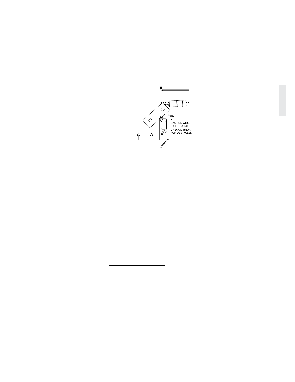
Right Turns: Negotiating a right-hand turn
while pulling a recreational vehicle can be
difcult. The operator may anticipate they can
not make the turn without entering into the
other lane or jumping the curb. A right-hand
turn can be negotiated using these tips:
When
approaching
a turn, look
into the mirror
to ensure the
lane to the left
is clear, then
move wide to
the left.
Prior to the
turn; the left
rear wheel
should touch
the center line of the road and driver’s
hip should be parallel to the roadside
curb of the corner being turned. This
will aid in avoiding a premature turn.
Slowly make the turn.
Check mirrors frequently. Be aware
of necessary clearance and space
management for the recreational
vehicle while negotiating the turn.
Left Turns: The turn should be made when
the driver’s hip reaches the center of the
intersection. If two lanes are available, take the
right hand lane. A vehicle or object located on
the left-hand side is easier seen.
Ascending a Grade:
When approaching an uphill grade, assess
the grade and length before beginning the
climb. Prepare early for long climbs.
IMPORTANT SAFETY TIP:
Turn on the four way flashers if road
speed decreases significantly under the
posted speed. Use pullouts if traffic is
building.
Descending a Grade:
Prepare to descend a grade at the crest of the
hill. Observe any signs indicating grade angle
and duration. The sign may suggest maximum
downhill speed according to the Gross
Combined Weight. The combined weight of
the two vehicle and recreational vehicle.
Night Driving:
Be well rested and alert when driving.
If necessary, nd a safe place to stop
and rest until ready to continue.
Avoid using any interior lights that
create a glare on the windshield. This
will decrease visibility.
Dim the dash lights to a comfortable
level to reduce the level of glare.
Extreme Heat and Hot Weather
Conditions:
Check tire pressure frequently when
traveling in hot conditions. Tire air
pressure increases with heat. Do not let
air out of a hot tire. The tires will return
to correct/previous tire pressure when
cool.
Winter and Cold Climate Conditions:
The recreational vehicle should be
prepared for cold weather use.
Keep speeds slow and steady; make
moves gradually and increase the
visual distance for a gain in reaction
time.
If the road or weather conditions are
treacherous, nd a safe place to stop
and wait for conditions to improve.
Remove any ice build-up from the
entry step to avoid accidental slipping.
020181c
12
DRIVING & SAFETY - 2
2013 HOLIDAY RAMBLER
During cold weather, tire pressure can
decrease. Check and ensure tires are at
proper ination pressure.
Wet Conditions:
The risk of hydroplaning is increased if
tires are worn or improperly inated.
Be aware that heavy rain or standing
water can affect brake effectiveness,
causing them to apply unevenly or
grab.
Refueling:
Be aware of the fuel port location on
the tow vehicle. There may not be
adequate space to turn around in the
parking lot in order to reposition for the
pump.
Check overhead clearance before
pulling through
the fuel island.
Be aware of the
concrete/steel
posts installed
around the fuel
island.
Avoid running
over the fuel
hose as it can
get caught and
cause damage to
the tow vehicle
or recreational
vehicle.
Use of gloves is
recommended for
refueling.
TRIp pREpARATION
The following
suggestions are a general
guideline to follow when
preparing for a trip.
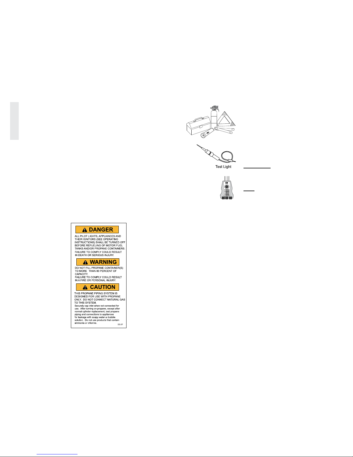
Items to Carry:
An emergency road
kit containing a
ashlight, road ares,
warning signs and a
re extinguisher.
Local, State and National Maps, as
well as a ‘Motor Carrier’ road atlas
for refueling station and truck repair
facility locations.
Hand tools, a 120 Volt AC polarity
tester, battery hydrometer and an
assortment of spare fuses.
Potable and non-potable water hoses,
a water pressure regulator and various
termination connectors for sewage.
Inspection:
Ensure all exterior items are stored or
secured (i.e. antenna, ceiling vents and
windows).
Evenly distribute and secure cargo.
Store heavy items near the rear axle
and lighter items toward the front to
prevent uneven stress and handling
problems.
Check all tires for accurate pressure
and physical condition. Look around,
above and under the recreational
vehicle for obstructions or leaks. Test
all exterior lighting: taillights, brake,
license plate and clearance lights.
Inside the recreational vehicle store
and secure heavier objects in the lower
cabinets to maintain a low center of
gravity for sway reduction. Secure
loose items to prevent weight shifts.
Store lighter items in the overhead
cabinets. Close and secure all cabinet
doors and drawers and shower door.
Turn off interior lighting.
CAUTION:
Open compartment doors slowly.
Cargo may shift during travel.
TIP:
Multi-purpose items, versatile clothing
and periodic removal of unused cargo
will streamline compartment storage
space.
hITchINg ThE TRAvEL TRAILER
Tow hitches come in a variety of shapes
and sizes for various applications. Generally,
hitches are classied either weight carrying or
weight distributing. A weight carrying hitch
connects the recreational vehicle to the tow
vehicle using a ball mount and hitch ball.
Weight distributing hitches use an adjustable
ball mount, hitch ball and spring steel levers
that redistribute tongue weight. A weight
distributing hitch is used in applications when
the suspension of the tow vehicle prohibits use
of a weight carrying hitch. In all cases, never
exceed the tow vehicle manufacturers Gross
Combination Weight Rating (GCWR).
090333f
020064b
020062
Polarity
tester
GB
GARDNER BENDER, INC
OPEN
GROUND
OPEN
NUETRAL
OPEN HOT
HOT/GRD
REVERSE
HOT/NEU
REVERSE
CORRECT
020155i
13
DRIVING & SAFETY - 2
2013 HOLIDAY RAMBLER
Tow Capacity and Class Ratings
Several components comprise a tow hitch
system. The weight rating of individual
components that are part of the towing system
must be greater than the gross weight of the
load being towed. To help dene weight
capacity of towing equipment, components are
classied into weight groups. Maximum tow
capacity is limited to the component with the
lowest weight rating in the tow hitch system.
Example: a ball mount may have a weight
rating of 5,000 lbs. but the hitch ball is rated
3,500 lbs. Maximum tow capacity is reduced
to 3,500 lbs. Many times a component will
have a Class weight rating. These groups are
shown in the chart:
WARNING:
Be sure the weight ratings of the ball
mount, tow ball and safety chains are
equal to or greater than the load. The
use of an extension to the receiver or
extended ball mount will significantly
reduce hitch receiver weight ratings.
Modifications to the hitch receiver, or
use of the hitch receiver other than
intended, can void the warranty of the
hitch receiver, tow vehicle chassis or
both.
CAUTION:
Never exceed the tow vehicle
manufacturers GCWR. Damage to
the tow vehicle suspension, frame,
drivetrain and/or tires can occur.
Inadequate GCWR of a tow vehicle
can lead to poor handling, mechanical
failure or unexpected sudden loss of
control leading to accident, injury or
death.
CAUTION:
It is highly recommended to install
a frame mounted hitch receiver on
the tow vehicle. A rear bumper is not
suitable in towing strength compared
to a frame mounted hitch receiver.
WARNING:
Do not tow a trailer or vehicle that
exceeds the rated capacity of the
hitch receiver. Overloading the hitch
receiver can cause unusual handling
characteristics and overstress the hitch
receiver and chassis. It could also void
the warranty.
Terms Used to Describe the Typical Travel
Trailer Hitch Components:
Hitch Receiver: Component tted to a
tow vehicle that receives a ball mount.
Ball Mount: A removable component
the hitch ball is bolted to that ts into
the receiver.
Sway Control: Device that ts
between the trailer frame and tow
vehicle hitch to reduce trailer sway.
Trailer Coupler: The socket and lock
assembly located at the front of the
trailer frame that receives and secures
the hitch ball.
Spring Bars: Spring steel levers that
afx between the trailer frame and ball
mount used to absorb and distribute
tongue weight.
Tongue Weight: Weight exerted on the
hitch ball by the trailer coupler.
Breakaway Switch: Engages the
trailer brakes if trailer uncouples in
transit.
WARNING:
Ensure the weight ratings of ball
mount, hitch ball and safety chains
are equal to or greater than the load.
The use of an extended ball mount
will significantly reduce hitch receiver
weight ratings.
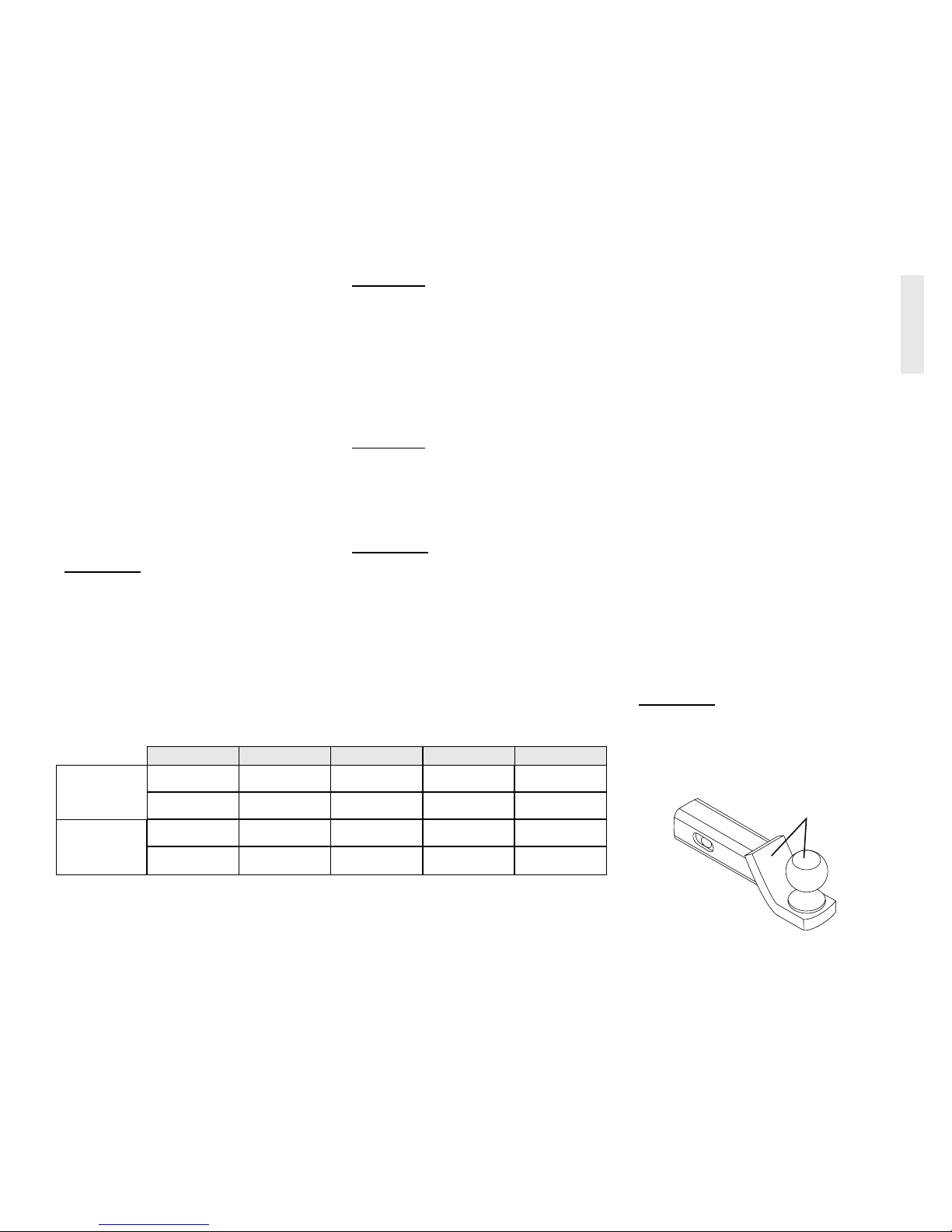
020268h
Weight Ratings
located here
Ball mount with
hitch ball
CLASS I CLASS II CLASS III CLASS IV CLASS V
Weight
Carrying
Hitch
TW - Up to 200
lbs.
WC TW - Up to
350 lbs.
TW - Up to 500
lbs.
TW - Up to 750
lbs.
TW - Up to
1,200 lbs.
GTW - Up to
2,000 lbs.
WC GTW - Up
to 3,500 lbs.
GTW - Up to
5,000 lbs.
GTW - Up to
7,500 lbs.
GTW - Up to
12,000 lbs.
Weight
Distributing
Hitch
--- --- ---
TW - Up to
1,200 lbs.
TW - Up to
1,400 lbs.
--- --- ---
GTW - Up to
12,000 lbs.
GTW - Up to
14,000 lbs.
GTW = Gross Trailer Weight. Weight of trailer fully loaded.
TW = Tongue Weight. Weight pushing down on Tow Ball.
WC = Weight Carrying. Weight carrying capacity of the Ball Mount.
WD = Weight Distributing. Weight carrying capacity of a weight distributing hitch.
14
DRIVING & SAFETY - 2
2013 HOLIDAY RAMBLER
Types of Hitches
Weight Carrying Hitch:
A weight carrying hitch relies on the tow
vehicle suspension, axles and tires to support
the added weight of a recreational vehicle. As
recreational vehicle weight and tongue weight
increase, the suspension on the tow vehicle is
adversely affected. Tongue weight will cause
the tow vehicle rear suspension to sag, also
transferring weight from the front suspension
to the rear. This negatively affects front end
alignment geometry, handling and braking
characteristics. Tow vehicle tires must be rated
and properly inated to support any added
weight while towing.
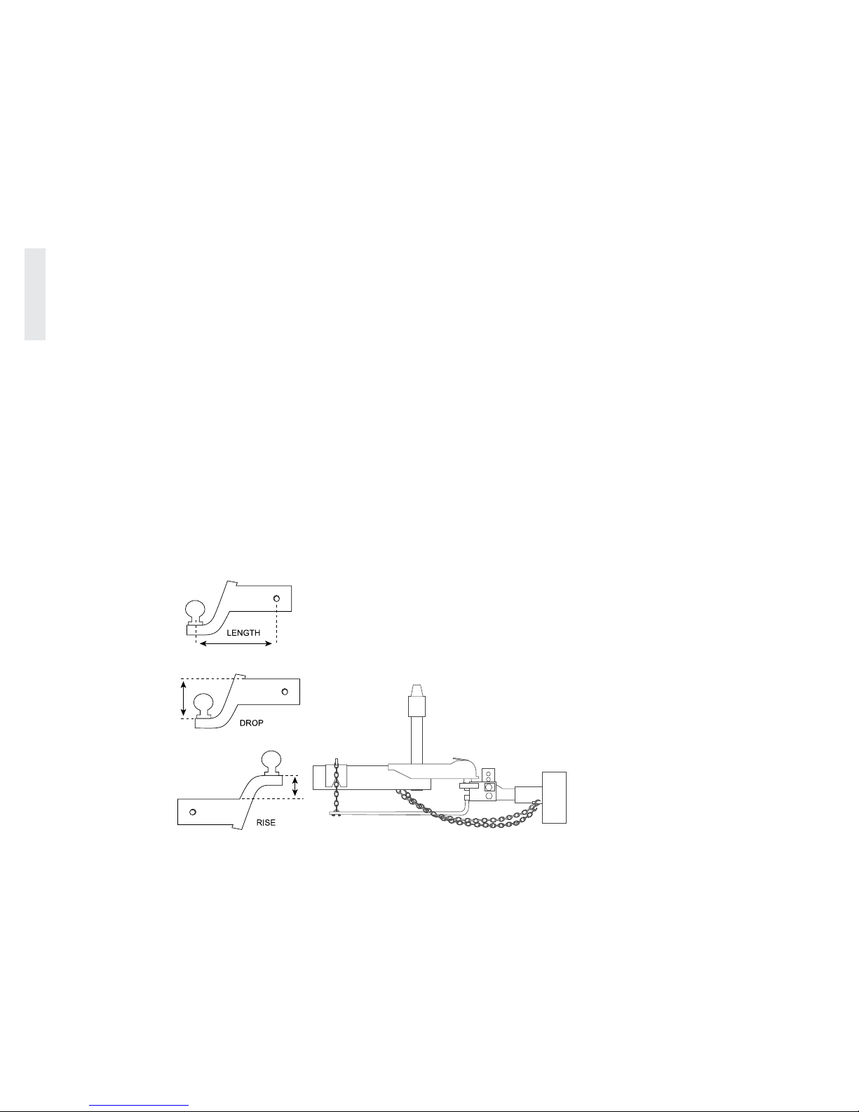
Ball Mount:
Ball mounts come in various congurations
and weight limitations. Three things should
be considered when selecting a ball mount:
weight rating, pin to ball center length and
rise/drop. The weight
rating of the ball
mount, tongue weight
and tow weight must
meet or exceed the
total load weight.
Pin to ball center
should not exceed
8”. Ball mounts of
longer length will
signicantly reduce the
weight rating of the
hitch receiver.
Observe weight reduction percentages that
may be listed on ball mounts longer than 8”.
Selecting how much rise or drop for a ball
mount is relative to hitch receiver height on
the tow vehicle and height of the coupler with
the recreational vehicle level.
Weight-Distributing Hitch:
Weight distributing hitches use spring bars
to absorb and re-distribute tongue weight to
all axles of the tow vehicle and trailer to help
offset tongue weight on the tow vehicle’s rear
suspension. Spring bars are made of spring
steel. They are an independent suspension
component. Spring bars are rated in pounds
capacity. Example, spring bars rated 500 lbs.
are half the capacity of 1000 lbs. spring bars.
Which weight rating to select is best left to
a professional to determine as selection is
determined by tongue weight, tow vehicle
suspension, any additional loads and to some
extent GCWR. Setting hitch ball height
and head angle will determine how much
weight the spring bars will offset. A weight
distributing hitch that is correctly setup should
sufciently offset tongue weight so the tow
vehicle’s suspension does not vary more than
¾” from its stock ride height.
The spring bars should be parallel to
the trailer frame and tow vehicle and
recreational vehicle should be near level. It is
recommended to have a professional perform
the initial setup. Improper adjustments and
ride angles that are not level can cause sway or
other undesirable towing characteristics.
Sway Control
Trailer sway (shtailing) is when the back
of the trailer oscillates left and right and can
potentially become quite severe. There may be
one or a combination of reasons that can cause
trailer sway.
Tongue weight – Tongue weight should
be 10-15% of Gross Trailer Weight.
Ensure adequate tongue weight.
Ride Attitude – The assembly of the
trailer and tow vehicle should be level.
Correct as necessary.
Load Balance – The load of the trailer
should be balanced left to right.
Tire Pressure – Check tire ination
pressure on the trailer and the tow
vehicle. Weigh the assembly (See
Weighing) then adjust tire pressures
accordingly.
Environmental Conditions – This can
be a cross wind, large vehicles (trucks
or busses) passing in the same direction
or opposite direction. Going downhill
can also exacerbate a sway condition
depending on grade, driving style and
road conditions.
If all these factors have been eliminated as
potential causes of sway, there are mechanical
sway control devices available. These devices
afx between the hitch system and the trailer.
Spring Bars
020097
Typical Weight
Distributing Hitch
020314

15
DRIVING & SAFETY - 2
2013 HOLIDAY RAMBLER
Trailer Coupler
Information regarding coupler classication,
weight rating and hitch ball diameter is
permanently marked on the trailer coupler. The
coupler uses a “clamp” to secure the hitch ball
inside the coupler socket. Open the coupler
latch prior to making the connection. After
lowering the coupler onto the hitch ball, close
the latch. Conrm the clamp has secured the
hitch ball into the socket by using the tongue
jack to slightly raise up on the hitch ball.
When properly secured, the tongue coupler
will attempt to lift the back of the tow vehicle.
Never place ngers around or inside the socket
while making the connection.
Hitch Ball
Hitch balls are available in three common
diameters: 1-7/8”, 2” and 2-5/16”. The larger
the diameter of the hitch ball, the higher the
weight rating. The diameter of the hitch ball
shank also factors into weight rating. Match
shank diameter with the hole in the ball mount
or weight distributing head. Shank clearance
should not exceed 1/16”. There should be at
least two additional threads extending past the
nut when the hitch ball is secure.
Safety Chains
Safety chains are required by law when
towing any load. Chains and fasteners must be
rated for the load being towed. Attach chains
to crisscross under the towing equipment.
Allow just enough slack in the chains to make
sharp corners without dragging on the road
surface.
If towed load should become uncoupled
from the hitch ball, the towing equipment will
be cradled by the safety chains. If the towed
load does uncouple, do not attempt to make a
sudden stop and aggravate the situation. Apply
the brakes with gentle, steady pressure. Pull
over to a safe location.
CAUTION:
Never loop safety chains around the
ball hitch. Use the provisions in the
hitch receiver to attach safety chains.
Connecting the Trailer
Weight Carrying:
An assistant will ease this process by guiding
the tow vehicle operator until the hitch ball is
located under the coupler socket.
Inspect all hitch related hardware for
safety integrity, tightness and damage.
Lower the tongue jack until the coupler
socket clears the hitch ball.
Open the coupler latch.
Back up the tow vehicle until the
hitch ball is directly under the coupler
socket.
Lower coupler until it is seated on the
hitch ball then close the latch.
Conrm the connection to ensure the
coupler clamp is below the ball and not
riding on top.
Raise the tongue jack completely. If a
footpad or wheel is removable, stow at
this time.
Attach the breakaway cable to the tow
vehicle. Allow enough slack for tight
turns. The breakaway switch cable
should be positioned on the tow vehicle
separate from the hitch assembly.
Attach the safety chains to proper
location on the hitch receiver. Never
loop chains around the hitch ball.
Connect trailer wiring harness to
the tow plug connection on the tow
vehicle.
The next step is checking the trailer
brakes. Close vents, windows and
doors and secure items before
performing this test. Drive forward and
check the trailer brakes by using the
manual feature on the brake control.
Weight Distributing:
An assistant will ease this process by guiding
the tow vehicle operator until the hitch ball is
located under the coupler socket.
Inspect all hitch related hardware for
safety integrity, tightness and damage.
Lower the tongue jack until the coupler
socket clears the hitch ball.
Open the coupler latch.
Back up the tow vehicle until the
hitch ball is directly under the coupler
socket.
Lower coupler until it is seated on the
hitch ball then close the latch.
Conrm the connection to ensure the
coupler clamp is below the ball and not
riding on top.
16
DRIVING & SAFETY - 2
2013 HOLIDAY RAMBLER
Extend the tongue jack until the jack
is supporting the tongue weight and
some tow vehicle rear suspension
weight. This will reduce tension when
installing the spring bars.
Select equal number of chain links so
spring bars carry equal tension. Hook
chains to spring bar clamps on trailer
frame. Use a tool to pry clamps over
center. Engage safety clip mechanism
on spring bar clamps. Spring bars
should be parallel with trailer frame
when complete.
Retract the tongue jack completely. If a
footpad or wheel is removable, stow at
this time.
Attach breakaway cable to the tow
vehicle. Allow enough slack for tight
turns. The breakaway switch cable
should be positioned on the tow vehicle
separate from the hitch assembly.
Attach the safety chains to proper
location on the hitch receiver. Never
loop chains around the hitch ball.
Connect trailer wiring harness to
the tow plug connection on the tow
vehicle.
The next step is checking the trailer
brakes. Close vents, windows and
doors and secure items before
performing this test.
Drive forward and check the trailer
brakes by using the manual feature on
the brake control.
NOTE:
Confirm the hitch is properly locked
before towing. Confirm spring bars
are adjusted for proper weight
distribution.
Ride Angle
The recreational vehicle must be level when
hooked to the tow vehicle. If the hitch is too
low, the nose of the recreational vehicle may
drag on high spots in the road. If the hitch is
too high, the tail end of the recreational vehicle
may drag. Either of these conditions will affect
towing stability.
When the tow vehicle and recreational
vehicle are level, the suspension will work
properly and within the design limits. If
instability is still present, an “Anti-Sway”
device may be necessary to ensure a smooth
safe ride and predictable towing.
NOTE:
The recreational vehicle should be in a
level position when hitched to the tow
vehicle.
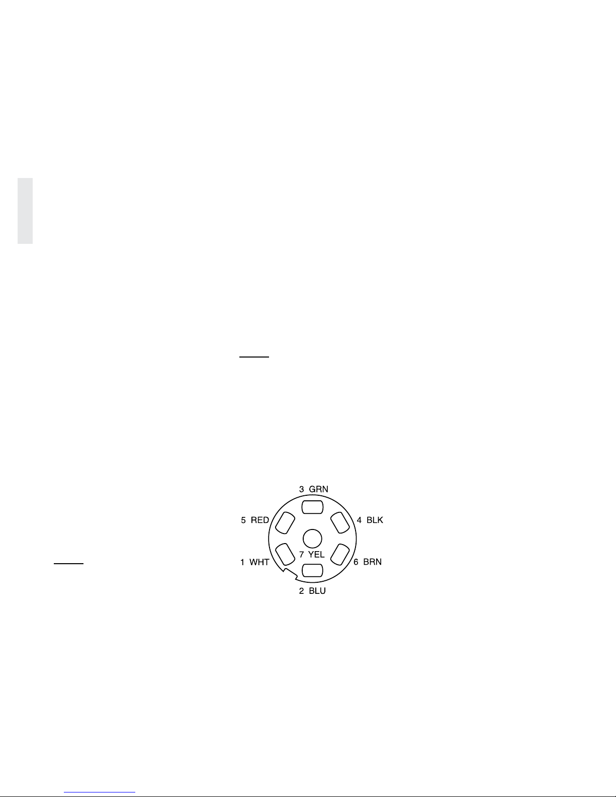
TOW pLug cONNEcTION
The recreational vehicle is equipped with a
wire harness located near the coupler. Current
draw should not exceed ten amps for each
designated light circuit.
The Tow Harness Wires are Color Coded:
1. White, 10 gauge - Ground
2. Blue, 12 gauge - Electric Brake
3. Green, 14 gauge - Tail, License &
Running Lights
4. Black, 10 gauge - Battery Charge
5. Red, 14 gauge - Left Turn & Stop
Lights
6. Brown, 14 gauge - Right Turn & Stop
Lights
7. Yellow, 14 gauge - Auxiliary Circuit
or Backup Lights.
Taillight Configuration:
Taillights come in different congurations
referred to as a 2-wire or 3-wire conguration.
A 2-wire conguration has all red lenses. A
3-wire conguration usually has red and amber
lenses. Amber is used for turn signals only and
red for taillight and brake light. These systems
are electrically different. Whenever hooking
a 2-wire system to a 3-wire system, or vice
versa, a converter box must be installed for
correct taillight function. A taillight converter
is available from auto and RV supply stores.
Do not attempt to wire a tow plug connector
if unfamiliar with these systems. A trained
technician will install the proper converter so
the taillights and turn signals work correctly on
the tow vehicle and the recreational vehicle.
080244
Viewed from Trailer End
17
DRIVING & SAFETY - 2
2013 HOLIDAY RAMBLER
BRAkES
Brake Controller
The recreational vehicle brakes are
controlled electrically. This requires a brake
controller be mounted inside the tow vehicle.
The brake controller varies voltage output to
change braking force.
Increasing voltage (gain) increases the
amount of braking force. To ensure safe
brake performance and timely reaction of
the recreational vehicle brakes, the brake
controller will need to be synchronized so the
tow vehicle brakes and recreational vehicle
brakes react progressively in unison.
Brake controllers come in two basic
congurations; Proportional and Time
Delayed. While both systems have adjustable
gain control, the difference is how and when
the control signal to the brakes is generated.
Proportional controllers use an
adjustable pendulum that senses the
amount of braking inertia. Changing
pendulum angle changes inertia
sensing and when the control signal is
generated.
Time Delayed controllers use a timer.
The control signal is generated shortly
after the brake lights illuminate.
Both gain and synchronization (proportional
controller) adjustment will require practical
application testing. Thoroughly review the
brake controller manufacturer’s instructions to
properly adjust controller settings. Testing will
involve increasingly aggressive stops on dry
pavement, free of sand and gravel. Optimum
synchronization and gain settings are correct
when the driver does not get the sensation the
recreational vehicle is pushing the tow vehicle
or the recreational vehicle is over-braking.
Gain settings will change based on load. Refer
to the instructions in the OEM brake control
manual on how to synchronize the brake
control system.
NOTE:
Refer to brake controller OEM
manual for further information and
adjustment settings.
CAUTION:
Verify the area is clear of
vehicular and pedestrian traffic
before performing a brake
synchronization test.
NOTE:
Minimum stopping distance is
achieved when wheels approach
lock-up. Wheel lock-up results in
poor vehicle stability and control.
Not all recreational vehicle brakes
are capable of wheel lock-up.
This depends on the load, brake
type, tire to surface traction. Gain
settings will change based on load.
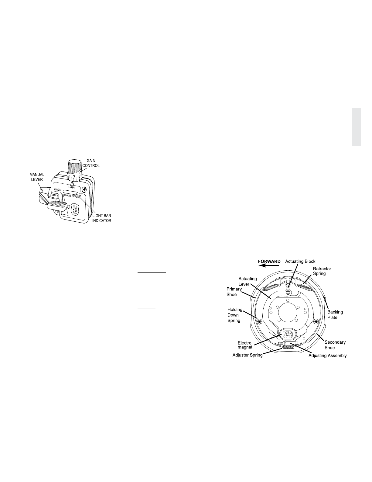
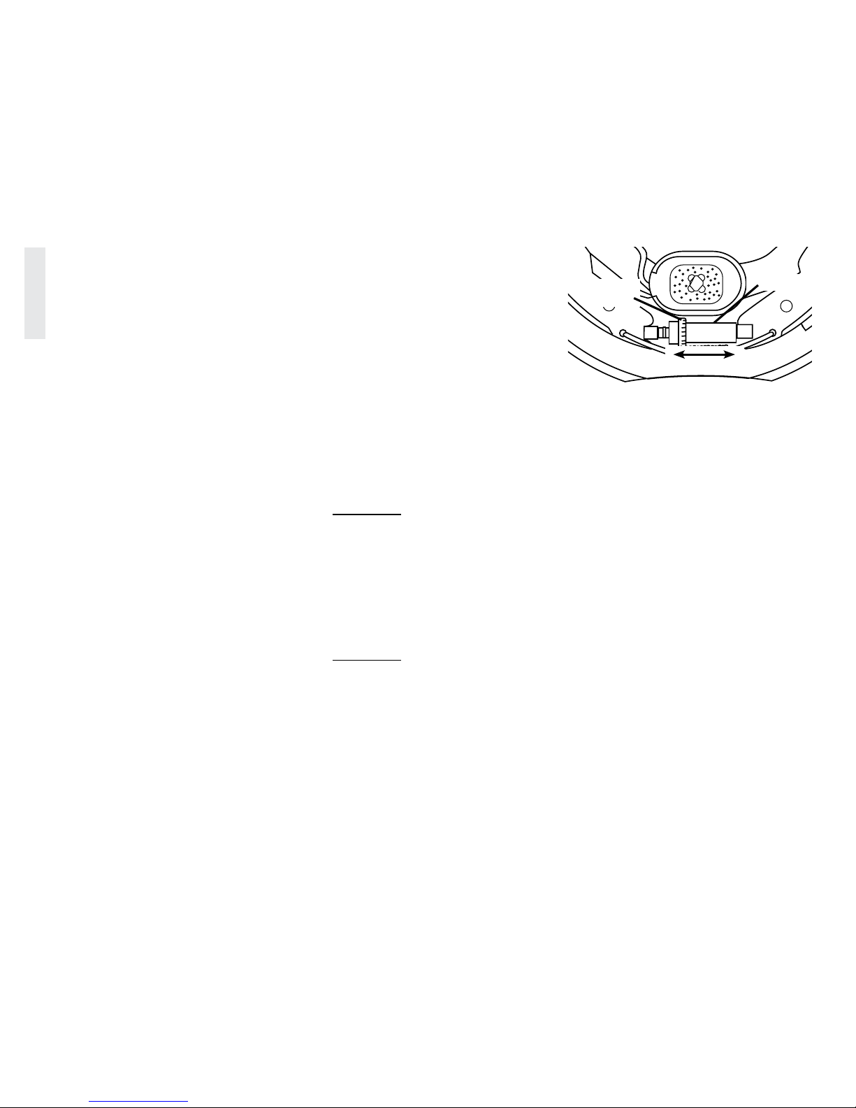
Electromagnets
The brake controller charges an
electromagnet. The magnet rides against a
machined surface of the brake drum. When
energized, it moves an actuating lever that
expands the brake shoes against the drum.
Increasing gain (voltage) to the electromagnets
causes the magnet to grip the machined surface
more rmly resulting in increased braking
force. It is normal for the electromagnets to
click when applying the brakes
The electromagnets and the machined
surfaces of the brake drum are inspected
during routine wheel bearing maintenance or
when brake performance degrades. This is an
indicator either the electromagnet is worn or
the brakes are out of adjustment or both. The
electromagnet is replaced as a component.
020310
Typical brake controller
Typical electromagnet brake assembly
090302
18
DRIVING & SAFETY - 2
2013 HOLIDAY RAMBLER
Bedding the Brakes
New brakes will require a “bedding” process
to properly seat and cure the brake shoes and
electromagnets. The process involves making
several brake applications (between 10 and
20) after which brake performance should
increase. When performing the bedding
process, select a road with limited or no trafc
and safe road conditions.
With the recreational vehicle properly
hitched including spring bars,
accelerate to approximately 40 mph.
Using the manual brake lever on the
brake control, apply only the trailer
brakes with brake control initially set
to approximately 50% gain. Slow to
approximately 20 mph.
Increase gain to work the trailer brakes.
Decrease gain if the wheels lockup.
Repeat the process several times.
Allow a cool down period between
applications to avoid overheating of
trailer brake components.
The brakes are now bedded. The
process will need to be repeated when
shoes and/or magnets are replaced.
Brake Adjustment
The brakes on the recreational vehicle
are not self-adjusting and require periodic
manual adjustment to maintain satisfactory
performance. Loss of braking performance
regardless of gain setting is an indication of
brakes needing adjustment. While loss of
performance can be caused by non-functioning
electromagnets, brake adjustment must also be
checked.
It is recommended to check brake adjustment
after the rst 200 miles if the recreational
vehicle is new or after brake shoes and/or
electromagnets are replaced. Regular
adjustments should be performed every 3,000
miles thereafter.
WARNING:
Brake adjustment requires elevating
the wheels and possible removal of the
brake drum for further inspection.
Improper technique in jacking and
supporting the frame and axles can
result in damage, injury or death.
Use only sufficiently rated heavy
duty hydraulic jack and jackstands
whenever elevating any wheel position.
WARNING:
Do Not go under the recreational
vehicle unless it is resting on properly
placed jack stands. Reference axle
and brake OEM manual for detailed
instructions.
1. Carefully elevate and securely
support the wheel with suitable rated
jack stand(s).
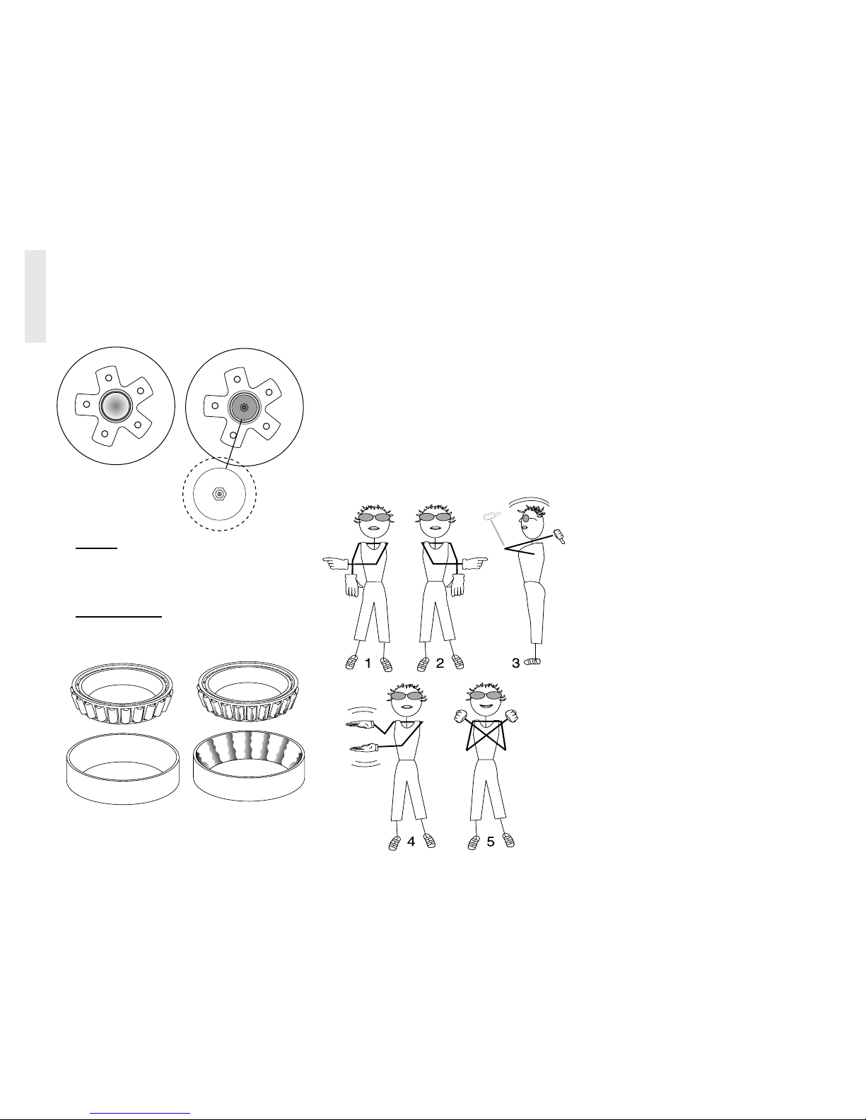
2. Remove adjuster inspection plug
located on reverse side of backing
plate opposite adjuster.
3. Rotate adjuster with screwdriver or
suitable tool until brake shoes expand
making wheel difcult to turn by
hand.
4. Rotate adjuster the opposite direction
until shoes have enough clearance to
allow wheel to turn freely with very
slight drag.
5. Uniformly adjust brake shoe
clearance on all wheels
ADJUSTER
ROTATE
HERE
Rotate adjuster to expand or retract brake shoes
090303c
19
DRIVING & SAFETY - 2
2013 HOLIDAY RAMBLER
If brake performance remains unsatisfactory,
the cause may be mechanical or electrical.
Have a qualied professional inspect and test
the system.
WARNING:
Do not continue operation if brake
performance is unsatisfactory. Have
a qualified professional inspect and
repair the braking system. Continued
operation can result in accident, injury
or death.
Brake Inspection
Recreational vehicle brakes must be
inspected at least once a year or more
frequently depending on use or anytime brake
performance declines. Replace magnets and
shoes when worn or scored as this affects
brake performance. Inspect the backing plate,
magnet arm, magnet and brake shoes. If
disassembled, all parts must be reassembled to
the same brake and drum assembly.
Inspect the magnet arm for any loose or
worn parts. Check shoe return springs, shoe
hold down springs and the adjuster spring
for stretch or deformation. Replace worn
components as necessary.
WARNING:
ASBESTOS DUST HAZARD!
Some brake shoe friction materials
contain asbestos. Observe all safety
protocols when servicing brakes:
1. Avoid creating or breathing dust.
2. Avoid machining, ling or grinding
the brake lining.
3. Do not use compressed air or a dry
brush for cleaning. (Dust can be
removed with a damp brush.)
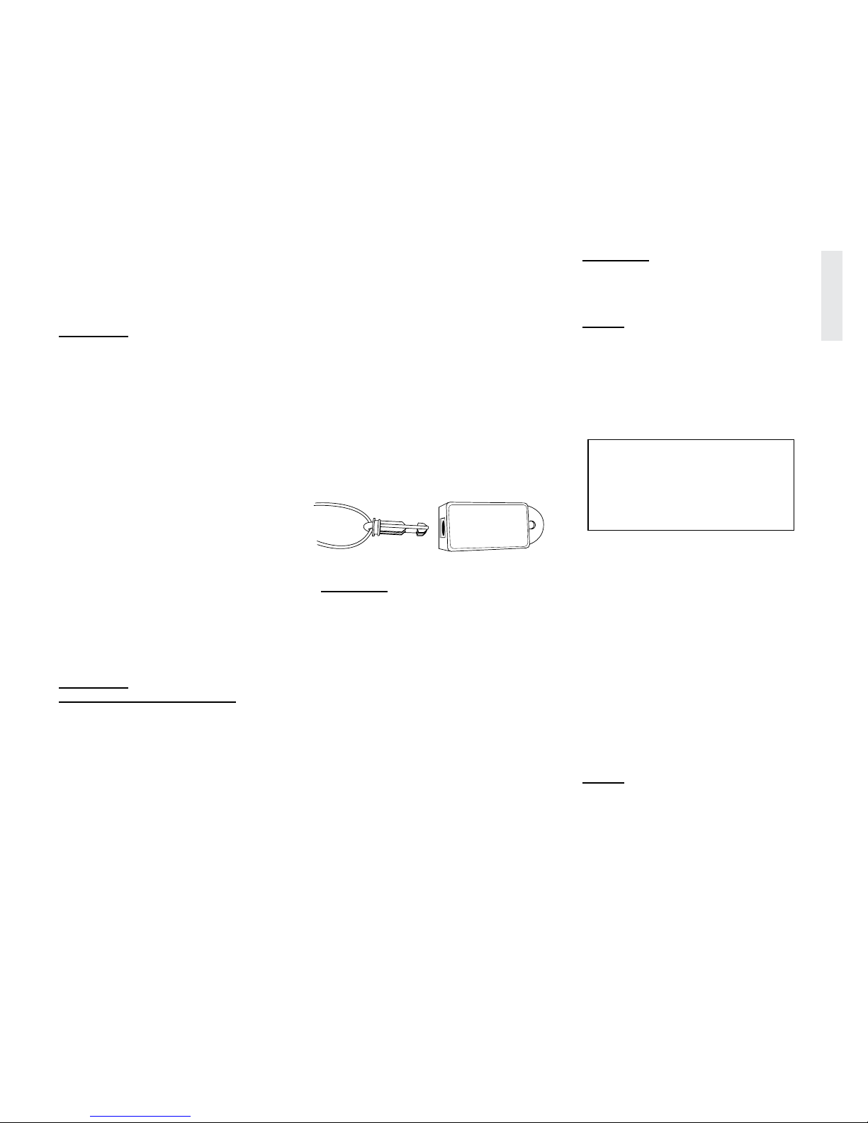
Breakaway Switch
The breakaway switch is located on the front
of the recreational vehicle. The breakaway
switch is a mandatory safety device that
activates the recreational vehicle brakes should
the recreational vehicle become unhitched
from the tow vehicle. Attach switch cable to
the tow vehicle framework. Ensure cable has
a direct line of pull should the recreational
vehicle become unhitched. The onboard
battery supplies power for the brakes. The
battery must be charged and in good condition.
Periodically test the breakaway switch to
assure the safety system is working.
CAUTION:
Attach breakaway cable in direct line
of pull to tow vehicle framework. Do
not attach cable to hitch ball, safety
chains or other compromising location.
To Test:
Hitch tow vehicle and recreational
vehicle. Do Not Connect Tow Plug!
Damage to the brake controller will
result if the breakaway system is
activated.
Pull out the breakaway switch
pin then attempt to drive forward.
The recreational vehicle will resist
movement if the breakaway system is
operating correctly.
CAUTION:
Unplug the tow connection before
testing the breakaway system! Damage
to the brake controller will result!
NOTE:
Lubricate the switch pin periodically
to ensure pin separation. Make sure
the pin is securely in place each time
the recreational vehicle is used. Do not
use the breakaway switch as a parking
brake. Continuous operation will
damage brake magnets and drain the
battery.
WhEEL BEARINgS
Wheel bearing dust caps can be equipped
with or without a grease zerk tting.
Regardless of dust cap style, the wheel
bearings should be inspected every year or
12,000 miles, whichever occurs rst. Wheel
bearings are adjusted with a small amount of
axial end oat. Correct end oat is essential to
maximize bearing service life. While dust caps
with a zerk tting may help with serviceability,
inspection is required to ensure the bearings
are in acceptable condition for continued
service.
NOTE:
The recommended lubricant is
Lithium grease with NLGI rating
GC-LB.
020320
Breakaway switch
SAFETY BREAKAWAY SWITCH
WILL NOT OPERATE
unless hooked to a power source
equivalent to or greater than an
automotive type 12 Volt, 12 amp-hour
wet cell battery.
20
DRIVING & SAFETY - 2
2013 HOLIDAY RAMBLER
Dust Caps with Zerk:
These caps provide serviceability with a
grease gun. Use a hand grease gun only when
servicing. Over-pressurization can damage the
grease seal contaminating the brake linings.
NOTE:
Do not mix grease base types.
Thoroughly remove old grease from all
surfaces when servicing the bearings.
INSPECTION:
Inspect the wheel bearings every year
or 12,000 miles, whichever comes first.
BAckINg up ThE REcREATIONAL vEhIcLE
The driver should be comfortable using the
mirrors and/or the co-pilot’s directions for
assistance. Practice backing up in a large,
unobstructed parking lot. Select a solid, level
site located on the roadside with a direct eld
of vision from the roadside mirror.
If the site is on the curbside, the driver will
have a blind spot when backing up. Stop
before backing into a site. Get out and observe
the area for soft ground, posts, large rocks, low
hanging tree limbs or other obstacles. When
site conditions are satisfactory, prepare to back
in carefully.
Make a wide turn then turn back the opposite
direction to set the recreational vehicle in a
position to maneuver into the space.
The driver may become disoriented by the
direction of the steering wheel in relation
to the direction of the recreational vehicle
when backing up. Move the bottom of the
steering wheel in the desired direction of the
recreational vehicle.
Example: If the desired direction of the
recreational vehicle is left, rotate the bottom
of the steering wheel left. If the recreational
vehicle moves in an undesirable direction,
pull forward just far enough to realign the
recreational vehicle with the space.
The co-pilot should stand safely at the left
rear corner of the recreational vehicle, within
view of the driver in the roadside mirror, and
use the hand signals for directing travel of
the rear of recreational vehicle. If the desired
direction of the recreational vehicle is left, the
co-pilot points left. This type of directional
signal is easily discerned in the mirror by the
driver. Keep directional signals steady until
movement is done.
The Five Directional Signals are:
1. Co-pilot uses left hand and arm held
horizontal with forenger pointing
right, to direct rear of recreational
vehicle right.
2. Co-pilot uses right hand and arm held
horizontal, with forenger pointing
left, to direct rear of recreational
vehicle to the left.
020083h
Bearing surface without
moisture damage.
090415
Bearing surface with
moisture damage.
090415b
090536
With Zerk Fitting
Without Zerk Fitting
Remove plug to
access zerk tting.
21
DRIVING & SAFETY - 2
2013 HOLIDAY RAMBLER
3. Co-pilot uses both arms and hands
parallel with thumbs pointing up and
to rear in a waving vertical motion.
This signals driver to maintain a
straight back direction.
4. Co-pilot holds arms vertically, hands
open with palms facing one another.
Start with a wide separation of the
hands. Gradually close the distance
between them in a rate appropriate to
vehicle speed to indicate the amount
of distance to a stopping point.
5. Closed sts indicate STOP.
LEvELINg
Leveling the recreational vehicle will require
an assortment of wooden blocks be placed
under the tires to level side to side. The tongue
jack is used to level the recreational vehicle
front to rear. Afx a pair of leveling gauges,
available at RV supply stores, to a front and
side corner of the recreational vehicle to
simplify the process. If a side is low, place an
appropriate amount of blocks in front of or
behind the tires on the low side. Use the tow
vehicle to pull the recreational vehicle tires
onto the blocks. See “Supporting Tires When
Leveling” in this section. It may be necessary
to build a ramp of wooden blocks. The blocks
must support tires across the entire width of
the tread to prevent tire damage. Once side to
side leveling is satisfactory, the tow vehicle
can be unhitched.
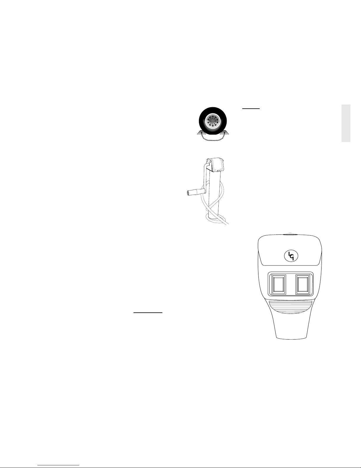
Operation:
Securely chock all wheels
of the recreational vehicle
to prevent movement.
Unhook the tow plug
connection and break
away switch from the tow
vehicle.
Adjust the tongue
jack to rest on
the ground or on
a wooden block.
Wooden blocks may
be placed under the
jack to gain additional
height.
Release the couplerlocking device and
raise the recreational
vehicle coupler to
clear the hitch ball.
Move the tow vehicle away from the
recreational vehicle.
Adjust the jack to level the recreational
vehicle front to rear.
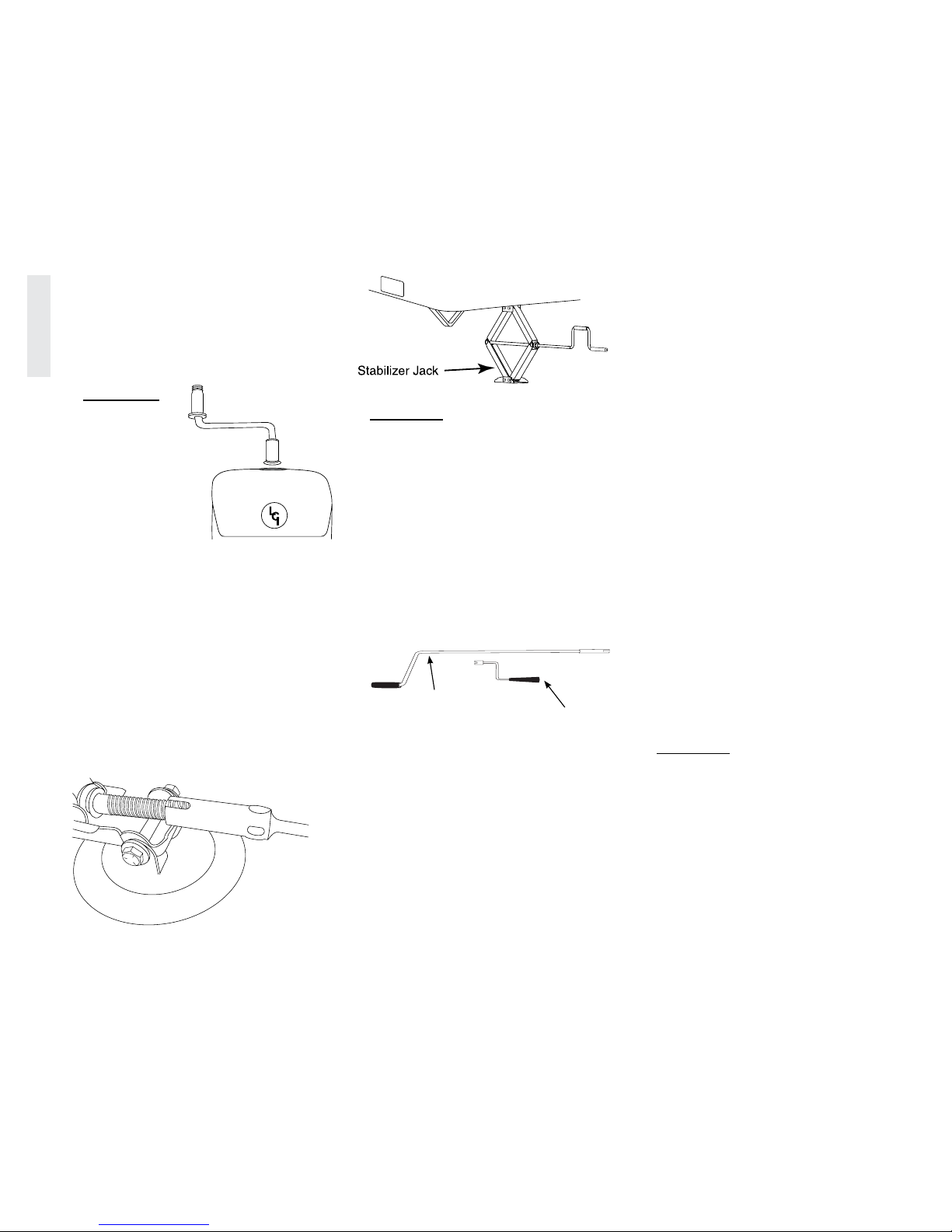
Once leveling is complete, lower
stabilizing jacks (optional equipment)
until the jacks contact the ground
or wooden blocks. Do not use the
stabilizer jacks for leveling on uneven
ground or to change tires.
WARNING:
Do not use the stabilizing jack(s)
for leveling on uneven ground or to
change tires. Do not use the front jack
to change tires or elevate any wheel
off the ground. Damage to the front
jack, stabilizer jack(s) and recreational
vehicle may occur.
NOTE:
In extreme cases, the use of leveling
ramps under the tires may be necessary
to level the recreational vehicle.
Electric Tongue Jack
A 12 Volt DC gear motor provides quick
hitching and unhitching of the recreational
vehicle. The operation is controlled by a single
push button. Manual operation can be used if
battery power is lost.
Power Extend/Retract:
Battery must be fully charged.
Press the extend/retract switch until the
desired height is obtained.
Release the switch.
The other switch activates the light.
Properly Chocked
Wheel
090368
Manual Tongue
Jack
020318
020047g
Electric tongue jack
22
DRIVING & SAFETY - 2
2013 HOLIDAY RAMBLER
Manual Extend/Retract:
Insert the crank handle.
Rotate the crank handle in the desired
direction until the desired height is
obtained.
Remove the crank handle.
WARNING:
The handle
can cause
injury if the
electric motor
is activated.
Remove
handle before
activating
motor.
Stabilizer Jacks (Optional)
The stabilizer jacks are mounted on the
front and rear roadside and curbside of the
recreational vehicle. These jacks are for
stabilizing only. Primary leveling is performed
with blocks under the wheels and the tongue
jack. Lower the stabilizing jacks after leveling
by using the crank handle until they rmly
contact the ground. Place wooden blocks under
the pads if necessary. Raise jacks by turning
the cranks counterclockwise.
CAUTION:
Do not use the stabilizing jack(s) for
leveling on uneven ground or to change
tires. Never use jack(s) to elevate any
wheel off the ground. Damage to the
stabilizer jack(s) and recreational
vehicle main frame can occur.
cRANk hANDLES
There are various crank handles used to
operate such items as the front power jack,
stabilizer jacks (optional), and undercarriage
mounted spare tire carrier. The crank handles
are located within the interior living area.
SET-up pROcEDuRE
The set-up procedure has information on
hooking up the utilities and preparing the
appliances for use. Specic information on the
slideout room, awning and leveling operation
is discussed in other sections. The set-up
procedure is only a guide as not all models
and oorplans are equally equipped. Locations
of some items will vary with options and
oorplans.
1. Level the Recreational Vehicle:
Follow the procedures and guidelines
for “Leveling” in this section.
The parking surface needs to
accommodate the weight placed on
the tongue jack.
If applicable, unlock any slide locks
which may secure the slide room.
Check for lateral clearance before
extending the slide out room.
2. Hook up utilities and prepare
appliances for use:
Open the primary propane tank valve.
Prepare the shore power cord for
connection. Uncoil and inspect
the cord. Perform necessary cord
maintenance. Install proper electrical
adapters if necessary. Operate electrical
appliances in sequence when hooked
to limited shore power service. Turn
shore power circuit breaker Off prior to
plugging in the shore power cord. (See
“Shore Power Hook-up” in Section 8.)
If possible, begin appliance operation on
propane for the rst 60 minutes. Switch
refrigerator operation to propane, start
the water heater and furnace (if needed).
CAUTION:
If shore power service is limited to 15
or 20 Amps, use of light duty extension
cords and electrical adapters will create
a voltage loss through the cord and at
each electrical connection. Line voltage
loss and resistance at each connection
can overheat electrical connections.
Damage to sensitive electronic
equipment may result.
020045
020045b
020360b
Stabilizer Jack Crank Handle
Manual Crank for Power Jack
020047g
Using manual crank
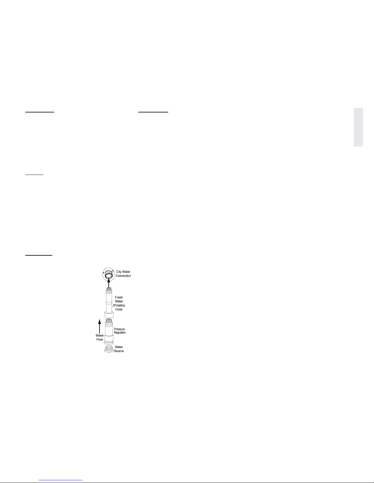
23
DRIVING & SAFETY - 2
2013 HOLIDAY RAMBLER
CAUTION:
Do not remove cover from the shore
power supply to troubleshoot electricity
to the recreational vehicle. Serious
personal injury or death may occur. If
there is no power to the recreational
vehicle inform the park manager. It is
the park manager’s responsibility to fix
any problems with the shore hook-up at
the site.
NOTE:
To avoid shore power overload when
hooked to 30 Amp service, determine
the current load prior to turning on
appliances or using interior outlets.
If cable service is provided, connect
a 75 Ohm RG59 or RG6 cable to the
cable connection located on roadside of
the recreational vehicle.
Hook a potable water hose to the city
water connection.
CAUTION
It is recommended to place a
pressure regulator at the water
source to protect the potable
water system from overpressurization. Some water
sources have high water
pressure, particularly in
mountainous regions. High
water pressure is anything
over 55 psi (pounds per
square inch). Excessive
water pressure may cause
leaks in water lines and/or
damage the water heater.
Excess pressure can cause
the water hose to swell and
burst.
WARNING:
Hose and hose fittings not
manufactured for potable water can
contain unsafe levels of lead. It is
highly recommended to use only fresh
water supply hoses manufactured for
potable water use.
Attach the sewer hose. Sewer drain
pipe diameters are generally either 3”
or 4”. Proper sewer hose adapters will
ensure against leaks or spillage. With
the sewer hose properly connected
open the grey water valve. The black
water valve remains closed until the
tank is full or until time of departure.
DRY cAMpINg
Below are suggestions to follow when
staying at a location that does not have
electrical, water or sewage hook ups. Plan
ahead and conserve resources.
Before arriving at the site, ensure batteries
are fully charged and properly maintained (See
“Battery Maintenance” in Section 8), the
fresh water tank and water heater are full and
waste holding tanks are empty.
Setting Up for Dry Camping:
Switch refrigerator operation to
propane (gas).
Turn on the water heater using propane
about an hour before hot water is
needed.
If the furnace is required, set the
thermostat temperature lower to
prevent excess cycling.
Check on small items that use
battery power, such as the porch and
compartment lights, etc. Even one light
accidentally left on reduces battery
reserves considerably.
Build a campre when spending
nighttime hours outdoors. Extinguish
the ames before retiring for the
evening. Many campgrounds place
wood or cement barriers between the
site space and re pit.
Keep ashlights handy. If interior lights
are needed, use one light in a central
location.
During the day it is still important to
conserve on energy. Turn on the water
pump only when using water.
Check the monitor panel frequently.
Keep track of water usage and battery
consumption.
Routinely check the propane level.
Remember the furnace uses more
propane in cold weather.
Leave shoes outdoors or at the entry
step to avoid tracking in dirt. Open
windows during the day instead of
using the roof air conditioner.
Plan what is needed from the
refrigerator prior to opening.
If no picnic table is available, eat at the
dinette table by candlelight.
Careful management of water is critical
when dry camping. Know the tank
capacities.
Do not ll the sink full of water to
wash a few dishes. Use disposable
dishes whenever possible.
040473d

24
DRIVING & SAFETY - 2
2013 HOLIDAY RAMBLER
BREAkINg cAMp
Preparing the recreational vehicle for travel
will require several tasks. Properly secure and
store items to prevent them from getting lost
or damaged. Below is a checklist to reference
when preparing to break camp.
Outside Checklist:
Disconnect the cable TV, lower the
television antenna (if applicable).
Retract the awnings and secure them
for travel.
Close propane tank valve.
Drain and ush the holding tanks.
Disconnect the sewer hose. Flush hose
with clean water. Store the hose. Fill
the fresh water tank. Disconnect and
store the fresh water hose. Remove the
water pressure regulator from the city
water faucet.
Turn shore power breaker off and
disconnect the power cord. Wind up
and store the power cord.
Secure all compartment doors and
entry door.
If applicable, raise all stabilizer jacks.
Interior Checklist:
If applicable, clear the slideout
room path and clean the oor. After
conrming compartment doors are
closed, retract the slideout room. After
the slideout is fully retracted, install
locking bar mechanism (if equipped)
and secure.
If applicable, secure and fasten the
bi-fold and pocket doors. Lock the
shower door.
Close roof vents and
windows.
Secure any loose, heavy
or sharp objects in case
of a sudden stop.
Close all cabinet doors
and drawers.
Turn off water heater,
water pump and furnace.
Turn the interior lighting off.
Walk through the interior and check for
any unsecured items.
Departure Checklist:
Check items in storage compartments
to ensure shifting or damage does not
occur.
Check above and under the
recreational vehicle and tow vehicle for
obstructions.
Close and lock outside compartment
doors.
Check operation of all exterior lights,
taillamp, brake, license plate and
clearance lights.
Inspect tires and wheels.
Secure and lock the entry door for
travel.
Secure all awnings and travel locks, if
applicable.
Carefully pull forward out of the
campsite. If necessary, clean the site
and check for any forgotten items.
EMERgENcY ROADSIDE pROcEDuRES
If an emergency situation occurs, carefully
apply the brakes and pull off the roadway a
safe distance from trafc (if possible). Set the
parking brake and turn on the hazard warning
ashers, especially when parked alongside
trafc lanes.
An emergency road kit should include at
least three reective warning signs, road ares,
a ashlight, spare automotive fuses and an
assortment of hand tools. The recreational
vehicle is equipped with a re extinguisher
inside, near the entry door. For added safety,
consider a separate re extinguisher. Display
road ares or reective warning signs if the
recreational vehicle is alongside the road for
any length of time.
Guidelines for placing the warning
triangles depend upon the road characteristics
and visibility. For example: The standard
placement is 10’, 100’ and 200’ from the rear
of the recreational vehicle when on a divided
highway or one-way road.
WARNING:
In case the recreational vehicle
requires towing, ensure all precautions
are followed. The manufacturer WILL
NOT cover damage to the recreational
vehicle caused by a towing company.
Never allow anyone to go under a
recreational vehicle while it is being
lifted by towing equipment. Severe
injury or death can occur.
040400
Screw potable hose
ends together to
prevent leakage and
insects from entering
the hose.
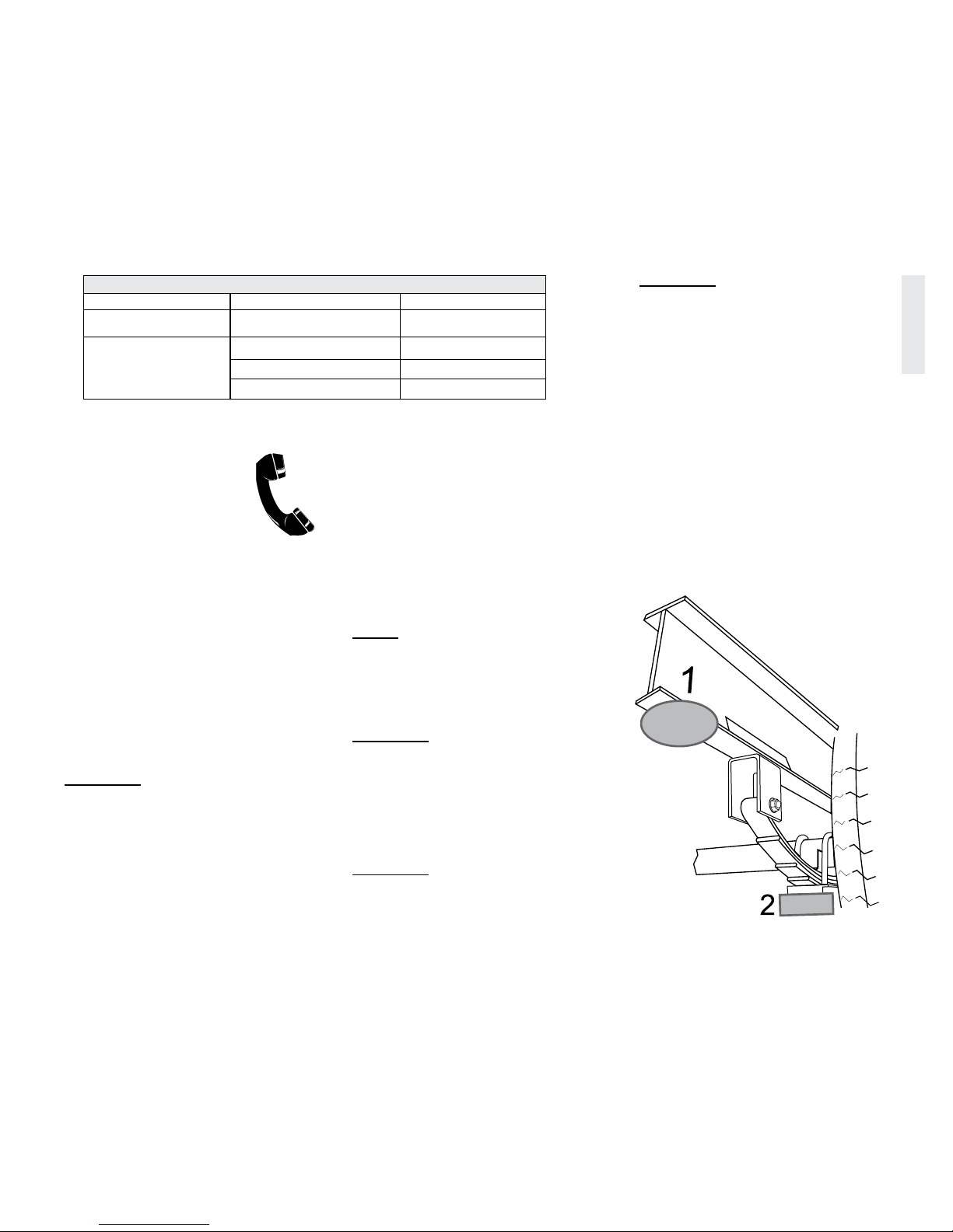
25
DRIVING & SAFETY - 2
2013 HOLIDAY RAMBLER
In Case of Flat Tire
In the event of a at tire, it is
recommended to call for roadside
assistance. Proper equipment is
necessary to change a tire due to the
size and weight of the recreational
vehicle. A professional service
technician will have the equipment and
training needed to repair or replace the tire.
In the Case of Sudden Tire Failure:
Avoid heavy braking.
Slowly move to a rm, level spot safely
away from oncoming trafc.
Turn hazard ashers on.
Set up ares or triangular reectors to
alert passing motorists.
Changing A Flat Tire
WARNING:
Tire changing is extremely dangerous.
It is highly recommended that this
procedure be performed by a qualified
professional service technician with
proper training and tools.
Tools Needed to Change Flat Tire:
Hydraulic Jack with at least half the
capacity of GVWR (found on the
Federal Certication Label on the
recreational vehicle).
2” x 12” x 3’ plywood.
Jack stand.
¾” thick plywood block.
Lug wrench.
Torque wrench and socket.
Flares or triangular reectors.
NOTE:
Hydraulic jack, lug wrench, jack
stand, 3’ plywood, ¾” plywood block,
torque wrench, flares and triangular
reflectors are not supplied with the
recreational vehicle.
WARNING:
Never allow anyone to crawl under the
recreational vehicle while being lifted
by the hydraulic jack or if a wheel
has been removed. Severe injury or
death can occur. Always remain a safe
distance from the road and oncoming
vehicle traffic.
WARNING:
Chock all remaining tires to
prevent accidental movement of the
recreational vehicle.
WARNING:
Do not use rear stabilizer jacks to
change tires or to elevate any wheel off
the ground. Do not use the tongue jack
to elevate any wheel off the ground.
Damage to the tongue jack, stabilizer
jack(s) and recreational vehicle may
occur.
To Change Flat Tire:
Chock the remaining tires to prevent
accidental vehicle movement.
Place the 3’ plywood on the ground. This
will help stabilize the hydraulic jack and
prevent it from sinking into the surface.
Place the hydraulic jack on the 3’ plywood
and raise the jack to snugly contact
frame (Location 1 preferred) or the axle
(Location 2).
CONTACT INFORMATION
Equipment Provider Phone Number
Recreational Vehicle
Monaco Customer Support 1-877-466-6226
Tires
Duro 1-800-537-2925
Freestar/Geostar, H188 1-800-537-2925
Goodyear 1-877-484-7376
070175
020306c
Jack at Location
1 (preferred) or
Location 2
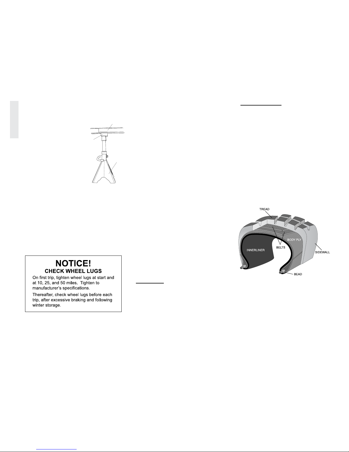
26
DRIVING & SAFETY - 2
2013 HOLIDAY RAMBLER
Loosen the lug nuts ¾ turn while wheel is
on the ground, but do not remove.
Raise the hydraulic jack until the tire clears
the ground.
Place ¾” plywood block
on jack stand and position
jack stand under the main
frame rail.
This provides additional
safety. DO NOT crawl
under the recreational
vehicle for any reason.
Remove lug nuts.
Remove tire from axle.
Follow the procedures under “Wheel
Mounting” in this section to mount the
replacement tire.
Torque lug nuts according to specications.
Remove jack stand and ¾” plywood block.
Lower hydraulic jack and stow the
jack, 3’ plywood, jack stand, ¾”
plywood block, wrenches, ares or
triangular reectors.
Re-check torque after removing jack.
Check the tire warranty for emergency
procedures. Save the old tire for any warranty
coverage. If the changed tire appears defective,
refer to the applicable warranty. Take the tire
directly to the nearest dealer for inspection.
TIRES
Tires designed for recreational vehicles are
a technically engineered product and not for
use on motor vehicles. Since the tire is the
only contact the recreational vehicle has with
road surface it is critical that proper ination
pressure be maintained. Improper pressure will
lead to abnormal wear or sudden tire failure.
The recreational vehicle must be weighed fully
loaded before proper tire ination pressures
can be determined.
The following information concerning tires
and weighing the recreational vehicle are set in
the order in which the process is performed.
The tire performs additional functions of
traction for moving, stopping and maintaining
lateral stability, as well as providing a cushion
for the recreational vehicle. To obtain the
maximum wear and best service of the tires it
is helpful to understand the components and
function of the tires.
WARNING:
Do Not exceed the tire manufacturer’s
maximum speed rating. Excess speed
can cause sudden tire failure resulting
in serious damage, injury or death.
Tire Components:
Tread: Provides traction and lateral
stability.
Belts: Stabilize and strengthen the tread.
Sidewall: Protects the side of the tire from
road and curb damage.
Body Ply: Gives the tire strength and
exibility.
Bead: Assures an air-tight t with the
wheel.
Inner Liner: Keeps air inside the tire.
080427k
090438
Wood
Block
Jack
Stand
Frame
020185i

27
DRIVING & SAFETY - 2
2013 HOLIDAY RAMBLER
Importance of Air Pressure
The most important factor in maximizing the
life of the tires is maintaining proper ination
pressure. Driving on any tire that does not
have the correct ination pressure for the
load of the recreational vehicle is dangerous
and may cause premature wear, tire damage,
sudden tire failure and/or loss of control of the
recreational vehicle.
An under-inated tire will create excessive
heat that may go beyond the design limits of
the rubber and radial cords and could result
in sudden failure. An under-inated tire will
also cause poor recreational vehicle handling,
rapid and/or irregular tire wear and increase
rolling resistance that results in decreased fuel
economy. An over-inated tire will reduce the
tire’s footprint/contact patch with the road,
thus reducing traction, braking capacity and
handling of the recreational vehicle.
Over-ination of a tire for the load will
result in a harsh ride, uneven tire wear and
susceptibility to impact damage. Maintaining
correct tire ination pressure for each loaded
wheel position on the recreational vehicle is of
the utmost importance and must be a part of
regular recreational vehicle maintenance.
WARNING:
Driving on an under-inflated tire can
exceed the design limits of the tire and
may damage the sidewall. A damaged
sidewall can burst upon inflation
resulting in serious damage, injury or
death. Aged tires are also susceptible
to sidewall damage.
Load Inflation Table
Federal law requires specications for the
tire maximum load rating be molded on the
sidewall of the tire. Air pressure amounts
depend on the weight of the recreational
vehicle when fully loaded. The “Load Ination
Table” in this section shows weights supported
by various air pressures. Using less air
pressure means a lesser load can be carried.
Always comply with the tire manufacturer’s
recommended pressure ination guide. Actual
weight of the recreational vehicle can vary
signicantly depending on how it is loaded.
Always comply with the manufacturer’s
guideline for optimum tire wear, ride and
handling. The tires of the recreational vehicle
are inated at the factory to pressure(s)
appropriate for the actual weight on each axle
in the unloaded, “as shipped” condition.
When the recreational vehicle is loaded for
travel, check and adjust ination pressure
according to the heaviest wheel position then
inate all tires with the same pressure. The
amount of ination pressure is indicated in the
load ination table for the weight carried by
the tire. Do not over-inate or under-inate the
tires.
The Gross Axle Weight Rating (GAWR) is
listed on the federal certication label attached
to the recreational vehicle is the maximum
allowable loaded weight on an axle.
When the actual loaded weight of the
recreational vehicle and the weight on each
axle is unknown, follow the recommended
tire ination pressure(s) listed on the federal
certication label. When loading a recreational
vehicle, never exceed the Gross Vehicle
Weight Rating (GVWR) or the GAWR for
each axle. Contact the tire manufacturer for
further information concerning proper ination
pressure and other tire issues.
 Loading...